3,350+ OPEN ACCESS BOOKS 108,000+ INTERNATIONAL AUTHORS AND EDITORS 115+ MILLION DOWNLOADS BOOKS DELIVERED TO 151 COUNTRIES AUTHORS AMONG TOP 1% MOST CITED SCIENTIST 12.2% AUTHORS AND EDITORS FROM TOP 500 UNIVERSITIES Selection of our books indexed in the Book Citation Index in Web of Science™ Core Collection (BKCI) Chapter from the book Wind Tunnels and Experimental Fluid Dynamics Research Downloaded from: http://www.intechopen.com/books/wind-tunnels-and- experimental-fluid-dynamics-research PUBLISHED BY World's largest Science, Technology & Medicine Open Access book publisher Interested in publishing with IntechOpen? Contact us at [email protected]

Welcome message from author
This document is posted to help you gain knowledge. Please leave a comment to let me know what you think about it! Share it to your friends and learn new things together.
Transcript

3,350+OPEN ACCESS BOOKS
108,000+INTERNATIONAL
AUTHORS AND EDITORS115+ MILLION
DOWNLOADS
BOOKSDELIVERED TO
151 COUNTRIES
AUTHORS AMONG
TOP 1%MOST CITED SCIENTIST
12.2%AUTHORS AND EDITORS
FROM TOP 500 UNIVERSITIES
Selection of our books indexed in theBook Citation Index in Web of Science™
Core Collection (BKCI)
Chapter from the book Wind Tunnels and Experimental Fluid Dynamics ResearchDownloaded from: http://www.intechopen.com/books/wind-tunnels-and-experimental-fluid-dynamics-research
PUBLISHED BY
World's largest Science,Technology & Medicine
Open Access book publisher
Interested in publishing with IntechOpen?Contact us at [email protected]

15
Wind Tunnel Tests on the Horn-Shaped Membrane Roof
Yuki Nagai, Akira Okada, Naoya Miyasato and Masao Saitoh College of Science and Technology, Nihon University
Japan
1. Introduction
Membrane structure is tensile surface structure consisted by textile. The materials used for
architectural membranes generally consist of a woven fabric coated with a polymeric resin
(Seidel & David, 2009). For example, PVC coated polyester fabrics and PTFE coated glass
fabrics are commonly used. Membrane structures provide widespan enclosures of great
spatial interest and variety require minimal supporting elements of "hard" structure and
provide very good overall levels of natural daylight. Membrane structures create various
forms. In the architecture and civil engineering area, membrane forms and systems are
divided into two categories, namely “pneumatic membrane” and “tensile membrane”
shown in figure 1 (Saitoh, 2003). The pneumatic membrane such as “BC Place (1983)”
Fig. 1. Structural Systems and forms of Membrane structures
www.intechopen.com

Wind Tunnels and Experimental Fluid Dynamics Research 326
(Janberg, 2011a) and “Tokyo Dome (1988)” (Shinkenchiku-Sha Co. Ltd., 1988) is supported by internal pressure. On the other hand, the tensile membrane keeps stabile by form and tensile force of itself. For example, “high point surfaces”, which are called “horn-shaped membrane” in this paper, are pulled to one or more high points from inside or outside. A Wind load is the most dominant load for light-weight structures such as the membrane structures. Therefore, verification against wind load is important for membrane structures. The engineer usually use the wind tunnel test and CFD simulation to evaluate the wind load for membrane structures. In recent years, the CFD simulation becomes major with the development of computers. But the wind tunnel test for membrane is sometimes useful to evaluate the wind pressure, because the membrane structure has complex form. From this points of view, this paper describes about wind tunnel tests of a membrane roof focusing on the horn-shaped membrane roof. The horn-shaped membrane roof divides into ‘stand-alone type’ and ‘multi-bay type’ as shown in figure 2. The stand-alone type is consisted by one unit horn-shaped membrane, and it is often used as temporally space without wall. On the other hand, the multi-bay type consists several horn units, and it is used as roofs of parking spaces, stands without wall, and as roofs of gymnasium hall with wall. These horn shaped membrane structures are supported by cables, struts, and so on. In general, there are three types of wind-tunnel test on the membrane roof, namely “Local Pressures Test”, “Area and Overall Wind Loads Tests” and “Aeroelastic Tests” as shown in figure 3 (Cermak & Isyumov, 1998). According to American Society of Civil Engineers (ASCE), “local pressure tests” use scaled static models instrumented with pressure taps (see figure 3(a)). These tests provide information on the mean and fluctuating local pressures on cladding and roof components. “Area and overall wind loads tests” are tests of wind load on specific tributary areas, using scaled static models and spatial or time averaging of the simultaneously acting local pressures (see figure 3(b)). These tests provide information on mean and fluctuating wind load on particular tributary area due to external or internal pressures, or both. “Local pressure tests” and “area and overall wind loads tests” measure wind pressures and wind forces acting on buildings around buildings. These wind tunnel tests need to consider the model scale depending on wind scale and time scale. On the other hand, “aeroelastic tests” use dynamically scaled models of buildings and structures (see figure 3(c)). These tests provide information on the wind-induced response of buildings and structures due to all wind-induced force, including those which are experienced by objects that move relative to the wind. In addition, these tests measure the overall mean and dynamic loads and response of buildings and structures, including displacements, rotations and accelerations. These tests have to consider stiffness scale in addition to model scale. This paper focuses on the local pressures tests. The wind local pressure around membrane roof was measured by scaled static models, and then wind pressure coefficients were calculated by dynamic pressure. In these tests, it is important to model the wind in the wind tunnel in order to obtain wind-effect data representative of full-scale conditions. In general, natural wind around buildings is duplicated using turbulent boundary layer flow which simulates a velocity scale, an aerodynamic roughness length of terrain, a gradient wind height of boundary-layer, and a scale of turbulence. The methods of modeling wind and similarly model are shown in guidelines and building standards of each country. This paper reports results under a uniform flow in the chapter 4 and 5, because of comparing effects for the model scale, the velocity and etc. as simply as possible. And then, chapter 6 presents the result under a turbulent boundary layer flow.
www.intechopen.com

Wind Tunnel Tests on the Horn-Shaped Membrane Roof 327
Tsukuba Expo., Japan(1985) Rest Dome, Japan(1989)
(a)Stand-alone Type
Fig. 2. Examples of the horn-shaped membrane roof (Saitoh & Kuroki, 1989; Janberg, 2011b; Shinkenchiku-Sha Co. Ltd., 1992; Shinkenchiku-Sha Co. Ltd., 2007)
Hyper Dome E, Japan (1990)
Kashiwa no Mori, Japan (2008)
(b) Multi-bay Type
Lord’s Cricket Ground, UK (1987)
www.intechopen.com

Wind Tunnels and Experimental Fluid Dynamics Research 328
Fig. 3. Three types of the wind tunnel tests for membrane roofs
1.1 Past research about the wind tunnel on the horn shaped membrane structures Wind pressure coefficients of typical building type such as box-type are defined in guidelines and standards in each country, but wind pressure coefficients of complicated shapes such as the horn-shaped membrane roof have not been sufficiently reported yet. The basic studies, which were about the theory and the analysis method, on the horn-shaped membrane roof were reported by F. Otto, M. Saitoh et al and also shown the wind- pressure coefficients of the horn-shaped membrane roof under regulated conditions in several reports and books (Otto, 1969; Saitoh & Kuroki, 1989; Nerdinger, 2005). In the resent years, studies on the numerical simulation against the horn-shaped membrane roof were reported by J. Ma, C. Wang et al (Ma et al., 2007; Wang et al., 2007). Furthermore, dissertation by U. Kaiser indicated wind effects on weak prestressed membrane structure which is 30m horn shaped membrane by aeroelastic models (Kaiser, 2004). There are many other references on this field. However, the basic date for the wind-force coefficient of the stand-alone and the multi-bay horn-shaped membrane roof has not been sufficiently reported yet.
1.2 The composition of this paper This paper composes nine chapters and three main parts as shown in figure 4. This paper describes three types of test. Before these tests, chapter 2 shows a form of the horn-shaped membrane roof and example of a technique to find this shape. Chapter 3 shows definitions of symbols and calculation formulas on this paper. Chapter 4 and 5 show wind tunnel tests under the uniform flow; stand-alone model tests parameterized model scales and velocity in chapter 4, and multi-bay models parameterized the number of the horn-unit in chapter 5. These tests indicate mean wind pressures around the horn-shaped membrane structures under the uniform flow. Chapter 6 shows wind tunnel tests of the stand-alone model under the turbulent boundary layer flow. In this chapter indicate mean wind pressures and peak wind pressures and compare these results with the results under the uniform flow.
(a) Local Pressures Test
(c) Aeroelastic Tests
(b) Area and Overall Wind Loads Tests
(b) Area and Overall Wind Loads Tests
www.intechopen.com

Wind Tunnel Tests on the Horn-Shaped Membrane Roof 329
Fig. 4. The composition of this paper
2. Form of the horn-shaped membrane roof
The horn-shaped membrane roofs have several kind of planar shape, namely a circle, a square and a hexagon based horn-shaped membrane roof. This paper describes about the square based horn-shaped membrane roof. In general, the membrane structure needs to find appropriate forms to resist external force. ‘European Design Guide for Tensile Surface’ by TensiNet presents some methods of form-finding for the membrane structures (Forster & Mollaert, 2004). This paper used nonlinear finite element method to find the appropriate form on the square based horn-shaped membrane. In this paper, the membrane material was defined as low stiffness material (see figure 5). On the other hand, a strut was defined as high stiffness material. A strut was transferred point B from point A in order to get the appropriate form using FEM analysis. A rise-span ratio H/L
Fig. 5. Form finding method on the horn-shaped membrane structures
Uniform flow
Turbulent boundary layer flow
Stand-alone model -----Parameter; model scale, velocity in the wind tunnel ---------------------------- Chapter 4
Multi-bay model --------Parameter; the number of the horn-unit----------Chapter 5
Stand-alone model ---------------------------------------------------------------Chapter 6
www.intechopen.com

Wind Tunnels and Experimental Fluid Dynamics Research 330
was defined as the ratio of a span L to a height of the horn-shaped roof H, and an appropriate form of H/L=0.2 was obtained by finite element method with geometrical nonlinear in this paper. Additionally, the top of strut was L/10 and there wasn’t a hole on the middle of the horn-shaped roof. The final shape get three-dimensional curved surface.
3. Definitions of symbols and calculation formula on this paper
The wind pressure coefficient was calculated based on The Building Standard Law of Japan (The building Center of Japan, 2004), Recommendations for Load on Buildings 2004 (Architectural Institute of Japan, 2004) and ASCE Manuals (Cermak & Isyumov, 1998). Definitions of the symbols in this paper are shown in figure 6. As for the signs of wind pressure coefficient, the positive (+) means positive pressure against the roof and the negative (-) means negative pressure against the roof.
Fig. 6. The definitions of symbols in this paper
The wind pressure coefficient is obtained from follows;
pj poj pijC C C (1)
ij
pijz
P PsC
q
, oj
pojz
P PsC
q
(2)
21
2z zq v (3)
in which Cpj is the wind pressure coefficient at measurement pressure tap j, Cpoj is the
external wind pressure coefficient at measurement tap j, Cpij is the internal wind pressure
coefficient at measurement tap j, Pij is the internal pressure at measurement tap j, Po is the
external pressure at measurement tap j, Ps is the static, or the barometric, pressure at a
reference location, zq is the mean value of dynamic pressure at the reference location z, ρ is
the density of the air, and zv is the mean value of wind velocity at the reference location z.
In this paper, the reference location z with the uniform flow means the position of the pitot
tube. On the other hand, the reference location z with the turbulent boundary layer flow was
obtained from the following equations;
www.intechopen.com
Wind Tunnel Tests on the Horn-Shaped Membrane Roof 331
2
Hz h (4)
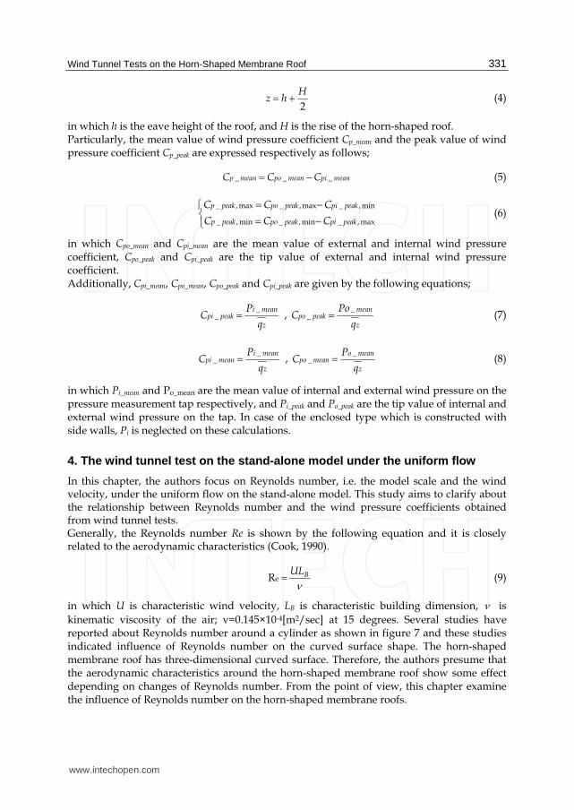
in which h is the eave height of the roof, and H is the rise of the horn-shaped roof. Particularly, the mean value of wind pressure coefficient Cp_mean and the peak value of wind pressure coefficient Cp_peak are expressed respectively as follows;
_ _ _p mean po mean pi meanC C C (5)
_ , max _ , max _ , min
_ , min _ , min _ , max
p peak po peak pi peak
p peak po peak pi peak
C C C
C C C
(6)
in which Cpo_mean and Cpi_mean are the mean value of external and internal wind pressure coefficient, Cpo_peak and Cpi_peak are the tip value of external and internal wind pressure coefficient. Additionally, Cpi_mean, Cpo_mean, Cpo_peak and Cpi_peak are given by the following equations;
_
_i mean
pi peakz
PC
q ,
__
meanpo peak
z
PoC
q (7)
_
_i mean
pi meanz
PC
q ,
__
o meanpo mean
z
PC
q (8)
in which Pi_mean and Po_mean are the mean value of internal and external wind pressure on the pressure measurement tap respectively, and Pi_peak and Po_peak are the tip value of internal and external wind pressure on the tap. In case of the enclosed type which is constructed with side walls, Pi is neglected on these calculations.
4. The wind tunnel test on the stand-alone model under the uniform flow
In this chapter, the authors focus on Reynolds number, i.e. the model scale and the wind velocity, under the uniform flow on the stand-alone model. This study aims to clarify about the relationship between Reynolds number and the wind pressure coefficients obtained from wind tunnel tests. Generally, the Reynolds number Re is shown by the following equation and it is closely related to the aerodynamic characteristics (Cook, 1990).
e R BUL
(9)
in which U is characteristic wind velocity, LB is characteristic building dimension, is
kinematic viscosity of the air; ν=0.145×10⁻⁴[m2/sec] at 15 degrees. Several studies have reported about Reynolds number around a cylinder as shown in figure 7 and these studies indicated influence of Reynolds number on the curved surface shape. The horn-shaped membrane roof has three-dimensional curved surface. Therefore, the authors presume that the aerodynamic characteristics around the horn-shaped membrane roof show some effect depending on changes of Reynolds number. From the point of view, this chapter examine the influence of Reynolds number on the horn-shaped membrane roofs.
www.intechopen.com

Wind Tunnels and Experimental Fluid Dynamics Research 332
Fig. 7. Reynolds number Re around cylinder
4.1 Outline of tests These tests measured local wind pressures on the stand-alone model using the Götingen
type wind tunnel as shown in figure 8. The Pj-Ps, which Pj is the pressure at the
measurement pressure tap j and Ps is the static pressure at the pitot tube, was measured
directly by the laboratory pressure transducer as a differential pressure and represents the
wind pressure acting at the particular pressure tap location j within the computer as sown in
figure 9.
Main parameters are the model scale and the wind velocity depending on Reynolds number
Re. Table1 shows conditions on this test. This test used the uniform flow in order to clarify
the influence of the parameter (i.e. the model scale and the wind velocity). The wind
velocities used the value at the pitot tube. This test neglected friction by the floor.
The six types of model which is open type and enclosed type in each model scale (i.e.
20cmx20cm, 30cmx30cm, and 60cmx60cm), were prepared for this test as shown in figure 10
and figure 11. These models were made from acrylic plastic and have 21 taps on the
20cmx20cm model and 30cmx30cm model, 39 taps on the 60cmx60cm model.
Fig. 8. Götingen type wind tunnel facility in Research Institute of Science and Technology, College of Science and Technology, Nihon University
www.intechopen.com

Wind Tunnel Tests on the Horn-Shaped Membrane Roof 333
Fig. 9. The wind pressure acting at the particular pressure tap location j
Wind Tunnel Facility Götingen type Wind Tunnel
Flow Uniformed Flow
Sampling Speed 500Hz
Sampling Time 10sec
Wind Velocity 4m/sec, 5m/sec, 6m/sec, 7.5m/sec, 9m/sec, 10m/sec, 15m/sec
Rise-Span Ratio H/L 0.20
Model Scale 20cmx20cm, 30cmx30cm, 60cmx60cm
Wall Open Type / Enclosed Type
Table 1. The parameter of the test
Fig. 10. Experimental models; open type and enclosed type
www.intechopen.com
Wind Tunnels and Experimental Fluid Dynamics Research 334
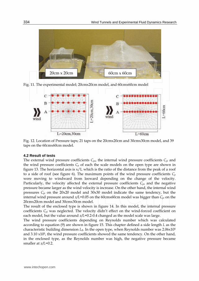
Fig. 11. The experimental model; 20cmx20cm model, and 60cmx60cm model
Fig. 12. Location of Pressure taps; 21 taps on the 20cmx20cm and 30cmx30cm model, and 39 taps on the 60cmx60cm model.
4.2 Result of tests The external wind pressure coefficients Cpo, the internal wind pressure coefficients Cpi and the wind pressure coefficients Cp of each the scale models on the open type are shown in figure 13. The horizontal axis is x/L which is the ratio of the distance from the peak of a roof to a side of roof (see figure 6). The maximum points of the wind pressure coefficients Cp were moving to windward from leeward depending on the change of the velocity. Particularly, the velocity affected the external pressure coefficients Cpo and the negative pressure became larger as the wind velocity is increase. On the other hand, the internal wind pressures Cpi on the 20x20 model and 30x30 model indicate the same tendency, but the internal wind pressure around x/L=0.05 on the 60cmx60cm model was bigger than Cpi on the 20cmx20cm model and 30cmx30cm model. The result of the enclosed type is shown in figure 14. In this model, the internal pressure coefficients Cpi was neglected. The velocity didn’t effect on the wind-forced coefficient on each model, but the value around x/L=0.2-0.4 changed as the model scale was large. The wind pressure coefficients depending on Reynolds number which was calculated according to equation (9) are shown in figure 15. This chapter defined a side length L as the characteristic building dimension LB. In the open type, when Reynolds number was 2.06x10⁵ and 3.10 x10⁵, the wind pressure coefficients showed the same tendency. On the other hand, in the enclosed type, as the Reynolds number was high, the negative pressure became smaller at x/L=0.2.
60cm x 60cm 20cm x 20cm
www.intechopen.com

Wind Tunnel Tests on the Horn-Shaped Membrane Roof 335
In particular, the results of figure 13 and figure 15 clarified that the wind pressure distributions changed near Re=1.2x10⁵ on the open type. Based on these result, the distribution of the mean wind pressure coefficient, which are Re>1.2x10⁵ and Re<1.2x10⁵, on the open type are shown in figure 16. This distribution illustrated great distinctions between Re>1.2x10⁵ and Re<1.2x10⁵ around the tip of the roof. These tests clarified that every test has to choose the appropriated model scale and velocity depending on the test conditions.
Fig. 13. The mean value of the external wind pressure coefficient Cpo _mean and the internal wind pressure coefficient Cp_mean i and the wind pressure coefficient Cp_mean under the uniform flow on the open type.
www.intechopen.com

Wind Tunnels and Experimental Fluid Dynamics Research 336
Fig. 14. The mean wind pressure coefficient Cp under the uniform flow on the enclosed type.
Fig. 15. Comparing the wind pressure coefficients obtained under each Reynolds number
Re<1.2×10⁵ (b) Re>1.2×10⁵
Fig. 16. Contour of the wind pressure coefficient on the open type
www.intechopen.com
Wind Tunnel Tests on the Horn-Shaped Membrane Roof 337
5. The wind tunnel test on the multi-bay model under the uniform flow
In most cases, the horn shaped membrane structure is used as the multi-bay type. The number of horn unit depends on the scale of the building and building uses. This chapter focuses on the number of the horn-unit. This experiment was carried out to clarify about the relationship between the number of the horn-unit and the wind pressure coefficient.
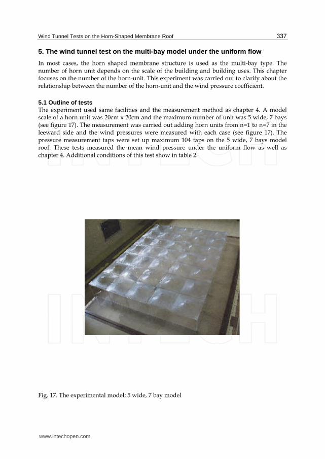
5.1 Outline of tests The experiment used same facilities and the measurement method as chapter 4. A model scale of a horn unit was 20cm x 20cm and the maximum number of unit was 5 wide, 7 bays (see figure 17). The measurement was carried out adding horn units from n=1 to n=7 in the leeward side and the wind pressures were measured with each case (see figure 17). The pressure measurement taps were set up maximum 104 taps on the 5 wide, 7 bays model roof. These tests measured the mean wind pressure under the uniform flow as well as chapter 4. Additional conditions of this test show in table 2.
Fig. 17. The experimental model; 5 wide, 7 bay model
www.intechopen.com

Wind Tunnels and Experimental Fluid Dynamics Research 338
Fig. 18. Parameter and pressure measuring taps on the multi-bay model
Wind Tunnel Facility Götingen type Wind Tunnel
Flow Uniform Flow
Sampling Speed 500Hz
Sampling Time 10sec
Wind Velocity 5m/sec, 10m/sec, 12.5m/sec, 14m/sec, 15m/sec
Rise-Span Ratio H/L 0.20
Model Scale 20cmx20cm(n=1), 100cmx140(n=7),
Wall Open Type / Enclosed Type
Table 2. The parameter of the test
www.intechopen.com

Wind Tunnel Tests on the Horn-Shaped Membrane Roof 339
5.2 Result of tests The mean wind pressure coefficients with the velocity 10m/s show in figure 19, because almost parameter indicated the same result. These results clarified that the unit numbers had little influence on the distributions of the wind pressure on each model. However, the value around boundary areas indicated the different value from the value of the inside area. These results provide that the n=5 model is able to estimate the value of n=7 model. Therefore, as an example, the distribution of wind pressure coefficient on the open type (n=5) shows in figure 20. But it is necessary to consider other conditions, particularly another wind direction, because these views depend on regulated conditions.
Fig. 19. The mean wind pressure coefficient under the uniformed flow with 10m/s
Fig. 20. Contour of wind pressure coefficient on the open type (n=5)
www.intechopen.com

Wind Tunnels and Experimental Fluid Dynamics Research 340
6. The wind tunnel test on the stand-alone model under the turbulent boundary layer flow
In general, structural engineers use wind pressures obtained from wind tunnel tests or simulations under the turbulent boundary layer flow when they design buildings. This chapter shows the wind tunnel test under the turbulent boundary layer flow in order to confirm the turbulent intensity around the horn shaped membrane roof. Additionally, this result is compared with the results under the uniform flow in chapter 4.
6.1 Outline of tests The wind tunnel facility is same as chapter 4. The turbulent boundary layer flow was made by the blocks which are made from styrofoam (see in figure 21 and 22). Two types of flow were prepared for this test as follows; a. Turbulent intensity is 16%, wind velocity is 7.2 m/s at approx. z=150mm, using twenty
seven the100x100x100mm blocks. b. Turbulent intensity is 25%, wind velocity is 5.7 m/s at approx. z=150mm, using twenty
seven the100x100x150mm blocks. The turbulent intensity was calculated as follows,
( )
( )( )
u zI z
V z
(10)
where u (z) is root mean square value of wind speed fluctuation at height z ,V(z) is mean
wind speed at height z.
Fig. 21. Photo of the facility and the model under the turbulent flow
www.intechopen.com

Wind Tunnel Tests on the Horn-Shaped Membrane Roof 341
Fig. 22. Outline of wind tunnel facility and layout of turbulent blocks
The 20cm x 20cm model was used in this test as well as chapter 4 and chapter 5. It was assumed that a model scale was 1: 50, a velocity scale was 1/5 at the full scale wind speed 30m/s. In this case, time scale was 11/125. In this chapter, the velocity pressure to calculate wind pressure coefficients was obtained from the mean velocity at z=150mm. Table 3 shows the experimental conditions. The main parameters are two types of the wind directions and the wind flows and the walls. The models and measurement taps show in figure 23. This test provides the mean wind pressure coefficients and the peak wind pressure coefficients by the equation (5)-(8).
www.intechopen.com

Wind Tunnels and Experimental Fluid Dynamics Research 342
Wind-Tunnel Facility Closed Circuit Wind Tunnel
Flow Turbulent boundary layer flow
Sampling Speed 500Hz
Sampling Time 20sec
Turbulent intensity (Iz) (a)15%, (b)25% ( at z=150mm)
Rise-Span Ratio H/L 0.20
Model Scale 100cmx20cm(n=1), 100cmx140(n=7),
Wall Open Type / Enclosed Type
Wind Direction 0deg, 45deg
Table 3. The parameter of the test
Fig. 23. Experimental models and measuring points
6.2 Result of tests The distributions of the wind pressure coefficient show in figure 24 and 25.The figure 24 is the result of the open type and the figure 25 is the result of the enclosed type. These figures show half panel of roof based on symmetrical shape. Generally, peak wind pressures around corner of roofs distinct from distributions of the internal area. However, this test showed that wind pressure coefficients around the middle of roof (i.e. the top of roof) were the maximum negative value. Furthermore, the wind direction influenced to the value of wind pressure coefficients. The peak value of wind pressure coefficients depended on the turbulent intensity, the peak wind pressure coefficients of Iz=25% exceeded the value of Iz=16%. The mean wind pressure coefficient, max./min. peak wind pressure coefficient at line A is shown in figure26 and 27. In addition to these results, the mean wind pressure coefficients with Re=1.0×10⁵ under the uniform flow, which showed in chapter 4, are illustrated in figure 26 and 27. The mean wind pressure coefficient indicate same tendency despite the difference of the flow. However, the turbulence affected the peak wind pressure coefficient on each model. As for the open type, the mean wind pressure coefficients under the turbulent flow indicated almost the same as the mean wind pressure coefficient under the uniform flow. On the other hand, as for the enclosed type, the mean wind pressure coefficients under Iz=25% and it under the uniform flow illustrated the different value.
www.intechopen.com

Wind Tunnel Tests on the Horn-Shaped Membrane Roof 343
Fig. 24. Contour of the wind pressure coefficient on the open model; comparison of turbulent intensity 16% (upper part) with 25% (lower part)
Fig. 25. Contour of the wind pressure coefficient on the enclosed model; comparison of turbulent intensity 16% (upper part) with 25% (lower part)
www.intechopen.com

Wind Tunnels and Experimental Fluid Dynamics Research 344
Fig. 26. Comparison of mean wind pressure coefficient with peak wind pressure coefficient on the open type
Fig. 27. Comparison of mean wind pressure coefficient with peak wind pressure coefficient on the enclosed type
Figure 28 and 29 show the comparison of mean wind pressure coefficients with peak wind force coefficients on the open type at the measuring point 01, 04, 15 and 21. The open type and the enclosed type show the same tendency at each measuring point. The measurement point 01 indicated that there is great distinction between the maximum peak wind pressure coefficient Cp_peak,max and the minimum peak wind pressure coefficient Cp_peak,min with 0, but the result of 45 degree didn’t indicate distinction between the Cp_peak,max and the Cp_peak,min, the distinction between the Cp_peak,max and the Cp_peak,min at the measurement point 15 and 21 is relatively small with each degree. The measurement point 04 shows the same tendency as the measurement point 01 with 0 degree. These results clarify that the areas affected by wind degree and the areas unaffected by wind degree were available on the roof.
www.intechopen.com

Wind Tunnel Tests on the Horn-Shaped Membrane Roof 345
Fig. 28. Comparison of mean wind pressure coefficients with peak wind force coefficients on the open type at the measuring point 01, 04, 15 and 21
www.intechopen.com

Wind Tunnels and Experimental Fluid Dynamics Research 346
Fig. 29. Comparison of mean wind pressure coefficients with peak wind force coefficients on the enclosed type at the measuring point 01, 04, 15 and 21
7. Conclusion
In this paper, the characteristics of the wind pressure coefficients on the horn-shaped membrane roof were presented by the wind tunnel tests. Particularly, the followings are clarified that;
The wind pressure coefficients of the stand-alone model depended on the model scale and the wind speed.
The value of the turbulent intensity affected on the value of the wind pressure coefficient, particularly at the top of the roof.
As for the multi-bay model, the increasing number of horn unit had no effect on the distributions of the wind pressure coefficients except for the boundary area.
Furthermore, the representative distributions of the wind pressure coefficient were shown on each parameter.
www.intechopen.com

Wind Tunnel Tests on the Horn-Shaped Membrane Roof 347
8. Acknowledgment
This work was supported by Japan Society for the Promotion of Science, Grant-in-Aid for JSPS Fellows, KAKENHI 22・7895. All of tests were carried out on “Research Institute of
Science and Technology, College of Science and Technology, Nihon University”. I have had the support of Takanori Fukuda, Yamashita Sekkei, Inc., Ayu Matsuda, Graduate School of Science and Technology,Nihon university for the experiments.
9. References
Architectural Institute of Japan. (2004). Recommendations for Load on Buildings (2004),
Architectural Institute of Japan, ISBN 481890556, Japan.
Cermak, J.E. & Isyumov, N., with American Society of Civil Engineers Task
Committee. (1998). Wind Tunnel Studies of Buildings and Structures (Asce Manual
and Reports on Engineering Practice), American Society of Civil Engineers, ISBN
0784403198
Cook, N.J. (1990). Designer’s Guide to Wind Loading of Building Structures Part 2: Static
structures, Laxton's, ISBN 0408008717
Forster, B. & Mollaert, M. (2004). European Design Guide Tensile Surface Structures, TensiNet, ,
ISBN 908086871x
Kaiser, U. (2004). Windwirkung auf schwach vorgespannte membranstrukturen am beispiel eines
30m-membranschirmes, Der Andere Verlag., ISBN 3899591623, Germany
Ma, J., Zhou, D., Li, H., Zhu, Z. & Dong, S. Numerical simulation and visualization of wind field
and wind load on space structure, Proceedings of IASS 2007, Beijing, 2007
Nerdinger, W. (2005). Frei Otto Complete Works: Lightweight Construction Natural Design,
Birkhäuser Architecture, ISBN 3764372311
Janberg, N. (2011). BC Place stadium, In: Nicolas Janberg's Structurae, March 21, 2011,
Available from: http://en.structurae.de/structures/data/index.cfm?id=s0000708
Janberg, N. (2011). Lord’s Cricket Ground Mound Stand, In: Nicolas Janberg's Structurae,
March 21, 2011, Available from:
http://en.structurae.de/structures/data/index.cfm?id=s0000694
Otto, F. (1969). Tensile Structures: Cables, Nets and Membranes v. 2, MIT Presse, ISBN
0262150085, USA
Saitoh, M. (2003). Story of Space and Structure -Structural Design’s Future, Shoukokusha, ISBN
4395006396, Japan
Saitoh, M. & Kuroki, F. Horn Type Tension Membrane Structures, Proceedings of IASS 1989,
Madrid, 1989
Seidel, M. & David, S. (2009). Tensile Surface Structures - A Practical Guide to Cable and
Membrane Construction: Materials, Design, Assembly and Erection, Wiley VCH, ISBN
3433029229, Germany
Shinkenchiku-Sha Co. Ltd. (1992). Hyper Dome E, In: Shinkenchiku March,1992,
Shinkenchiku-Sha Co. Ltd. ISSN 1342-5447, Japan
Shinkenchiku-Sha Co. Ltd. (1988). Tokyo Dome, In: Shinkenchiku May, 1988, Shinkenchiku-
Sha Co. Ltd. ISSN 1342-5447, Japan
www.intechopen.com

Wind Tunnels and Experimental Fluid Dynamics Research 348
Shinkenchiku-Sha Co. Ltd. (2007). BDS Kashiwanomori Auctionhouse, In: Shinkenchiku
October, 2007, Shinkenchiku-Sha Co. Ltd. ISSN 1342-5447, Japan
The building Center of Japan. (2004). The Building Standard Law of Japan June 2004, The
building Center of Japan. , ISBN 4-88910-128-4, Japan
Wang, C., Zhou, D. & Ma, J. The interacting simulation of wind and membrane structures,
Proceedings of IASS 2007, Beijing, 2007
www.intechopen.com

Wind Tunnels and Experimental Fluid Dynamics ResearchEdited by Prof. Jorge Colman Lerner
ISBN 978-953-307-623-2Hard cover, 709 pagesPublisher InTechPublished online 27, July, 2011Published in print edition July, 2011
InTech EuropeUniversity Campus STeP Ri Slavka Krautzeka 83/A 51000 Rijeka, Croatia Phone: +385 (51) 770 447 Fax: +385 (51) 686 166www.intechopen.com
InTech ChinaUnit 405, Office Block, Hotel Equatorial Shanghai No.65, Yan An Road (West), Shanghai, 200040, China
Phone: +86-21-62489820 Fax: +86-21-62489821
The book “Wind Tunnels and Experimental Fluid Dynamics Research†is comprised of 33 chaptersdivided in five sections. The first 12 chapters discuss wind tunnel facilities and experiments in incompressibleflow, while the next seven chapters deal with building dynamics, flow control and fluid mechanics. Third sectionof the book is dedicated to chapters discussing aerodynamic field measurements and real full scale analysis(chapters 20-22). Chapters in the last two sections deal with turbulent structure analysis (chapters 23-25) andwind tunnels in compressible flow (chapters 26-33). Contributions from a large number of international expertsmake this publication a highly valuable resource in wind tunnels and fluid dynamics field of research.
How to referenceIn order to correctly reference this scholarly work, feel free to copy and paste the following:
Yuki Nagai, Akira Okada, Naoya Miyasato and Masao Saitoh (2011). Wind Tunnel Tests on The Horn-shapedMembrane Roof, Wind Tunnels and Experimental Fluid Dynamics Research, Prof. Jorge Colman Lerner (Ed.),ISBN: 978-953-307-623-2, InTech, Available from: http://www.intechopen.com/books/wind-tunnels-and-experimental-fluid-dynamics-research/wind-tunnel-tests-on-the-horn-shaped-membrane-roof
Related Documents


