3,350+ OPEN ACCESS BOOKS 108,000+ INTERNATIONAL AUTHORS AND EDITORS 115+ MILLION DOWNLOADS BOOKS DELIVERED TO 151 COUNTRIES AUTHORS AMONG TOP 1% MOST CITED SCIENTIST 12.2% AUTHORS AND EDITORS FROM TOP 500 UNIVERSITIES Selection of our books indexed in the Book Citation Index in Web of Science™ Core Collection (BKCI) Chapter from the book Applied Computational Fluid Dynamics Downloaded from: http://www.intechopen.com/books/applied-computational-fluid- dynamics PUBLISHED BY World's largest Science, Technology & Medicine Open Access book publisher Interested in publishing with IntechOpen? Contact us at [email protected]

Welcome message from author
This document is posted to help you gain knowledge. Please leave a comment to let me know what you think about it! Share it to your friends and learn new things together.
Transcript

3,350+OPEN ACCESS BOOKS
108,000+INTERNATIONAL
AUTHORS AND EDITORS115+ MILLION
DOWNLOADS
BOOKSDELIVERED TO
151 COUNTRIES
AUTHORS AMONG
TOP 1%MOST CITED SCIENTIST
12.2%AUTHORS AND EDITORS
FROM TOP 500 UNIVERSITIES
Selection of our books indexed in theBook Citation Index in Web of Science™
Core Collection (BKCI)
Chapter from the book Applied Computational Fluid DynamicsDownloaded from: http://www.intechopen.com/books/applied-computational-fluid-dynamics
PUBLISHED BY
World's largest Science,Technology & Medicine
Open Access book publisher
Interested in publishing with IntechOpen?Contact us at [email protected]

15
Use of Fluid Dynamic Simulation to Improve the Design of Spouted Beds
Rodrigo Béttega1, Ronaldo Guimarães Corrêa2 and José Teixeira Freire2
1Federal University of Uberlândia, School of Chemical Engineering 2Federal University of São Carlos, Department of Chemical Engineering
Brazil
1. Introduction
The use of spouted beds in numerous chemical and pharmaceutical industrial processes and in the agricultural industry has become popular principally because they enable high rates of heat and mass transfer to take place between system phases. However, despite the advances achieved through research into spouted beds over the more than 50 years since their invention, it continues to be difficult to obtain detailed information regarding the hydrodynamics of this equipment. The constant movement of the particles and the geometric characteristics of the equipment are the principal factors complicating this evaluation. More specific information is still required about scaling up spouted beds and using data from half-column beds to infer data for full column beds. The half-column technique applied for hydrodynamic evaluation of spouted beds is very old. Nevertheless, many authors have stated that great care must be taken in their application to obtain experimental data for use in representing full-column spouted bed phenomena. The use of optical fiber sensors is currently one of the most commonly recommended techniques for this type of measurement. However, measuring the particle dynamics by inserting optical fiber sensors may produce inaccurate results, as calibration is extremely difficult and the sensors may cause perturbations within the bed. With regard to scaling up, larger spouted beds tend to be less stable and consequently harder to control and operate. This issue is difficult to study using experimental techniques because it relates directly to constructing beds on different scales. The flexibility of computational fluid dynamics, allied to the reliability of the simulated results that have already been proven by a range of studies, can contribute to this area. It enables the analysis of scaling up data in different configurations and scales and using fewer experimental modules, making it possible to conduct studies that remain difficult in the laboratory. With regard to the study of fluid movement, the most recent studies of fluid mechanics are still based on the same Navier-Stokes equations. Although they were proposed approximately 200 years ago, analytical solutions for the Navier-Stokes equations are known for just a few cases due to the non-linear nature of the partial differential equations (PDAs). There is still little knowledge of analytical solutions for this mathematical class, making it impossible to obtain a solution for arbitrary regions and general boundary conditions. These are the principal reasons why analytical evaluation of the movement of the fluids is very difficult. In light of this, treatments using experimental tests are
www.intechopen.com

Applied Computational Fluid Dynamics
322
predominant in this study. The costs involved in certain experiments and limited representative data make it necessary to improve the mathematical modeling of the problem. The advent of computers in the '80s and their improved storage and processing capabilities have led to accelerated growth in the numerical simulation of fluid mechanics and heat transfer (Computational Fluid Dynamics – CFD) and its use in different areas. Computational fluid dynamics can be defined as the set of computational methods used to solve physical and physico-chemical problems occurring in dynamic fluids by applying sophisticated numerical and computational tools. By using these powerful numerical simulation tools, it is now possible to obtain detailed and accurate results for flows with the most diverse characteristics, among which multiphase gas-solid flow stands out. The speed of evolution of computational codes, allied to the consequent improvement in the simulated results, is making CFD an increasingly important analysis tool, both in terms of process design at laboratory or industrial scale. This chapter describes new advances achieved using CFD numerical modeling in studies of cylindrical and semi-cylindrical spouted beds. These studies were conducted with the aim of evaluating the mathematical model parameters, as well as exploring numerical simulation applied to semi-cylindrical spouted bed in the assessment of hydrodynamic data pertaining to cylindrical beds. Recent research involving CFD and spouted beds is highlighted and discussed throughout this text with the aim of presenting recent advances in research in this area.
2. Mathematical modelling
2.1 Mathematical modeling of general multiphase flow The basic axioms of fluid dynamics are the conservation laws, specifically, conservation of mass, conservation of linear momentum, and conservation of energy. The combination of these mathematical equations provides a fluid dynamic description of single-phase systems well defined and reliable. However, the development of a mathematical model to represent a general multiphase flow is still a great challenge to researchers due to the complexity of phenomenona involved on it. Currently in gas-solid flows, although the equations are not yet clearly defined, there are several approaches available, especially for engineering problems. In gas-solid flow modeling there exist the Eulerian approach, which is based on the hypothesis of a continuous medium for the description of the individual behavior of each phase (fluid or solid phase), and the Lagrangian approach, which is based on the individual movement of each particle in the flow. The Lagrangian approach gives a direct description of the particulate phase movement by mapping the path of each individual particle present in the phase. In this mathematical model, the movement of each particle is described by ordinary differential equations in Lagrangian coordinates. Consequently, the velocity of each particle, as well as its trajectory, can be determined from the integration of the Lagrangian equations of the particle. The Lagrangian approximation is especially useful to describe the transient nature of the particle movement. To solve a Lagrangian equation for a given particle, the behavior of the gas phase and of the neighboring particles must be known beforehand. In some cases, the behavior of the fluid phase can be determined using an Eulerian approach. As the gas and the particulate phases are linked by gas-solid effects, a large number of interactions are necessary to obtain the convergence of the solution for all phases.
www.intechopen.com

Use of Fluid Dynamic Simulation to Improve the Design of Spouted Beds
323
Lagrangian modeling is limited in its application by the large computational requirements for its solution. Due to its high processing cost, this approach is normally applied in cases in which the particulate phase can be considered diluted or in cases of flow of isolated particles for which the multi-fluid approach (Euler-Euler) is not appropriate. In this chapter, mathematical modeling will be limited to the Eulerian approximation, which is commonly applied to the solution of fluidized bed and spouted bed flows, among others. In the Eulerian approach, each phase is assumed to obey the continuum assumption. The continuum assumption considers solid phase as continuous, rather than discrete. Consequently, properties such as density, pressure, temperature, and velocity are taken to be well-defined at infinitesimal volumes, and are assumed to vary continuously from one volume to another. This approach is basically an extension of the mathematical modeling of a single-phase flow to a multiphase flow. However, since the fluid phase and the particulate phase actually are not continuous media at any moment, forms of constructing a phase continuum should be established. The transported magnitudes of each pseudo continuous phase, or even of the turbulence model of each phase (in the case of turbulent flow), must be determined. Furthermore, the phase interactions must be expressed in a continuous form. A fundamental step in the construction of a continuous model is the correct determination of the “fluid element” of the continuous medium. This element or control volume must be determined so that the particles present are sufficient to ensure that this volume has macroscopic properties, such as temperature or velocity. At the same time, the size of this element must be sufficiently small in comparison to the system dimensions from a macroscopic viewpoint to allow the use of the continuous phase concept. Based on this, we present below a mathematical modeling of multiphase flow using the Euler approach. The manual of the software Fluent® was used as a reference to describe this modeling (Fluent, 2006).
In the description of multiphase flow as a continuous interpenetrant, the concept of phase volumetric fraction q is introduced. This fraction represents the space occupied by a certain phase in the global flow; the momentum and mass conservation laws will be applied to each of the phases. In this way, the volume qV of a phase (either solid or fluid) is defined by:
q q
V
V dV (1)
where:
1
1n
(2)
The effective density of a phase q is:
ˆq q q (3)
where q is the specific mass of phase q .
The continuity equation of phase q is determined from:
1
n
q q q q q pq qp qp
v m m St
(4)
www.intechopen.com
Applied Computational Fluid Dynamics
324
where:
qv
- velocity of phase; pqm - mass transfer of a p phase to a q phase; qpm - mass transfer of a
q phase to a p phase; qS - generation of mass for the q phase; n - number of phases of the
flow.
The mechanisms of mass transfer between phases, as well as the mass generation term, can be
defined in different ways. However, these terms are commonly considered null in common
gas-solid flow problems of particulate systems. The solution of Eq. 4 for all the secondary
phases present in the flow together with Eq. 2 gives the volumetric fraction of the primary
phase of the flow. This mathematical treatment is common to fluid-fluid and granular flows. Momentum conservation balance for phase q is given by the following equation:
, ,
1
qq q q q q q q q q q
n
pq pq pq qp qp q lift q vm qp
v v v p gt
R m v m v F F F
(5)
where: q – tensor of viscous stresses of phase q ; pqv
– phase relative velocity; pqR
– force
of interaction between phases; qF
– external body force of phase q ; qliftF ,
– lift force; qvmF ,
–
virtual mass force; p – pressure shared by the phases; qp – pressure of phase q ; g -
gravitational acceleration.
The viscous stress tensor q of phase q is obtained by:
2
3T
q q q q q q q q qv v v I
(6)
where q represents the shear viscosity of phase q and q represents the bulk viscosity of phase q . Relative velocity of the phases is defined as follows:
For 0 ;mass transfer to phase q
pq pq p qp qm v v v v ;
For 0 ;mass transfer to phase p
pq pq q qp pm v v v v .
The force of interaction between the phases depends on friction and pressure, among other factors. This force must respect the conditions pq qpR R
and 0qqR . To describe this
interaction, it is possible to solve this force by:
1 1
n n
pq pq p qp p
R K v v
(7)
where qppq KK is the coefficient of exchange of momentum between phases. In multiphase flows, it is possible to include the effects of the lift force acting on the
secondary phase. The lift forces act on a particle due mainly to the velocity gradients in the
primary phase flow, and it is more important in flows with large particles and low packing.
The lift force action on a secondary phase p in a primary phase q is calculated as:
0.5lift q p p q qF v v v (8)
www.intechopen.com
Use of Fluid Dynamic Simulation to Improve the Design of Spouted Beds
325
In most cases, the lift force is negligible when compared to the drag force. If its effects are truly significant, the terms of the force of ascension must be included in the equations of conservation of momentum for both phases considered:
, ,lift q lift pF F (9)
The effect of virtual mass force is important when the secondary phase p accelerates in relation to the primary phase q , and more significant when the secondary phase density is much smaller than the primary phase density. In the Eq. 10 is expressed this effect:
0.5q q p p
vm q p
d v d vF
dt dt
(10)
The inertia of the primary phase that is found by the accelerating particles exerts a “virtual
mass force” effect on the particles. The term qd
dt denotes the material derivative in phase q ,
which by definition is:
dv
dt t (11)
The force of the virtual mass is added to the right side of the momentum equation for both phases: , ,vm q vm pF F
. The conservation of energy in the Eulerian modeling is described by a separate equation for the enthalpy of each phase:
1
:n
qqq q q q q q q q q q q pq pq pq qp qp
p
ph u h u q S Q m h m h
t t
(12)
Where: qh – specific enthalpy of phase q ; qq
– heat flow; qS – source term that includes the enthalpy sources (due to chemical reaction or radiation); pqQ – enthalpy exchange between the phases. The heat exchange between the phases must be calculated using the local balance conditions: pq qpQ Q and 0qqQ . The previously presented equations represent the global model for the solution of the velocity field of an arbitrary multiphase flow using the Euler-Euler approach. The next section will present the models used by the software Fluent® to solve a solid-fluid flow with more details of the adopted steps and equations involved.
2.2 Mathematical modeling of spouted bed systems To describe the behavior of granular solid-fluid multiphase flow, the software Fluent® uses multi-fluid modeling, as previously described. The shear stress in the solid phase is obtained from an analogy between particles in random movement in the solid phase, and from the molecules moving in a certain gas phase. The result of the shock between the solid phase particles is treated as being analogous to the shock between gas molecules, taking into account the lack of shock elasticity in the solid phase. As in a gas, the intensity of the fluctuations determines the stresses, the viscosity, and the pressure of the solid phase; the kinetic energy associated with the velocity fluctuations is described by a pseudothermal
www.intechopen.com

Applied Computational Fluid Dynamics
326
temperature called granular temperature, which is proportional to the square of the random movement of the particles.
The mathematical model is presented next for the case of two-phase solid-fluid flow, where p represents the particulate solid phase (secondary phase) and q is the fluid phase (primary phase). The mass transfer between the phases is neglected in this modeling aiming to obtain a simplified fluid dynamic model, but its effects can be included, as previously discussed.
2.2.1 Continuity equation Considering the mass transfer between phase null, the continuity equation gives the phase volumetric fraction:
0q q q q qv fluid phaset
(13)
0p p p p pv solid phaset
(14)
2.2.2 Momentum conservation From Eq. 5, including the indicated simplifications, and changing the indexes, we obtain the momentum conservation equation for the fluid and the solid phases:
, ,
1
qq q q q q q q q q q
n
pq p q q lift q vm qp
v v v p gt
K v v F F F fluid phase
(15)
, ,
1
pp p p p p p p p p p p
n
qp q p p lift p vm pq
v v v p p gt
K v v F F F solid phase
(16)
where pp is the pressure of the granular solid phase and n is the number of phases that constitute the mixture, here n = 2. Having presented the simplified equations (Eq. 15-16), next we discuss the pressure and viscosity of the solid phase, as well as the drag between phases, which are critical variables in the modeling of this type of flow. The spouted bed has regions of high and low volumetric fraction of solids (annulus and spout, respectively). Gidaspow’s model (Gidaspow et al., 1992) is commonly used to represent the momentum transfer coefficient between phases in spouted beds since it results from the Wen & Yu (1966) model for the diluted phase region and the Ergun (1952) model for the dense phase. Thus, the Gidaspow’s model (Gidaspow et al., 1992) is described as below:
2.653, 0.8
4
p q q p q
pq qp D q qp
v vK K C
d
(17)
www.intechopen.com

Use of Fluid Dynamic Simulation to Improve the Design of Spouted Beds
327
2
1150 1.75 , 0.8
p q q p q p q
pq qp qq p p
v vK K
d d
(18)
The drag coefficient ( DC ) is given by:
0.687241 0.15 Re
ReD q p
q p
C . (19)
Relative Reynolds coefficient (pRe ) is calculated with the following equation:
Req p p q
pq
d v v
(20)
For granular flows in compressible regime (i.e., when the volumetric fraction of the solids is smaller than the maximum allowed value), the solid phase pressure must be included in the equation of conservation of momentum for the granular phase. Due to the distribution of the velocities for the particles, a variable called granular temperature, which appears in the pressure and viscosity equations of the solid phase, is added to the model. The granular temperature is a measure of the variation of kinetic energy of the particles caused by their shock. One of the possible formulas for the pressure of solids is given by Lun et al. (1984), in which the pressure equation is constituted of a kinetic contribution and a contribution of the collision of the particles:
20,2 1p p p p p pp p pp pp e g (21)
In Eq. 21, ppe represents the restitution coefficient for the collision of the particles and ppg ,0 is the radial distribution function. The restitution coefficient must be altered, depending on the characteristics of the particulate solid. The radial distribution function is a correction factor that alters the probability of collision between the particles when the granular phase is dense. This function can be interpreted as a non-dimensional distance between spheres:
0ps d
gs
(22)
where s is the distance between the particles. It is possible to observe that for a diluted solid phase 0, 1s g . On the other hand, when the solid phase gets close to the packing limit 0s and 0g . The radial distribution function is closely related to the X factor of the theory of non-uniformity of gases (Chapman & Cowling, 1991). X is equal to the unit for rarefied gases and increases, tending to infinite, when the molecules are so close that movement is not possible. The literature has different formulas for the radial distribution function, which is given by Ogawa et al. (1980):
113
0,,max
1p
ppp
g
(23)
www.intechopen.com
Applied Computational Fluid Dynamics
328
Where p is the volume fraction of solid phase and ,maxp is maximum packing limit. The tensor parameters are determined by the granular kinetic theory. The viscous stress tensor comprises stresses due to the shearing viscosity and the bulk viscosity, resulting from the exchange of quantity of movement due to the movement of the particles and their collision. A component that results from the friction between the particles can be included to calculate the effects that occur when the solid phase reaches maximum volumetric fraction. The collisional, kinetic, and frictional effects are added to give the shearing viscosity of the solid phase ( p ):
, , ,p p col p kin p fr (24)
Collisional effect (Eq. 25) and kinetic contribution (Eq. 26) are described by Gidaspow et al. (1992):
12
, 0,
41
5
pp col p p p pp ppd g e
(25)
2
, 0,
0,
10 41 1
596 1
p p p
p kin pp p pp
p pp pp
dg e
e g
(26)
The bulk viscosity ( s ) comprises the resistance of the particles of the granular phase to compression and expansion. Equation (27) can be used for this viscosity, according to Lun et al. (1984):
12
0,
41
3
ps p p p pp ppd g e
(27)
In dense low velocity solid phase flows, in which the solid fraction is close to the maximum packing limit, the generation of stresses results mainly from the friction between the particles. One of the forms to calculate the effect of friction in the stresses is using Eq. (28) (Schaeffer, 1987), where is the internal friction angle and 2DI is the second invariant of the stress tensor.
,
2
sin
2
pp fr
D
p
I (28)
In granular flows with high volumetric fractions of solids, the effects of collisions between particles become less important. The application of the granular kinetic theory in such cases would, therefore, be less relevant, as the effect of friction between the particles must be taken into account. To overcome this problem, the software Fluent® used a formula of the effect of friction extended for the combined application with the granular flow kinetic theory.
Stresses due to friction between particles are normally written in Newtonian form following Eq. 29, where friction represents the stress due to frictional effects.
Tfriction friction friction p pP I u u
(29)
www.intechopen.com

Use of Fluid Dynamic Simulation to Improve the Design of Spouted Beds
329
The resulting stress of the friction effects is added to the stress derived from the kinetic theory when the volumetric fraction of the solids exceeds a certain critical value. This value is normally considered as 0.5 when the flow is three-dimensional and the value of the packing limit of the solid phase is 0.63, thus:
p kinetic frictionP P P (30)
p kinetic friction (31)
The pressure due to friction is obtained mainly by semi-empirical form. The viscosity can be obtained by applying the modified Coulomb law, which gives the expression:
22
frictionfriction
D
P sen
I
(32)
The friction pressure can be determined with the model described by (Johnson & Jackson, 1987):
,min
,max
j
p p
friction k
p p
P Fr
(33)
where the coefficients are j =2 and k =3 (Ocone et al., 1993). The friction coefficient is
assumed to be a function of the volumetric fraction of the solids (Eq. 34) and the viscosity of
friction is thus given by Eq. 35.
0,1 pFr (34)
sinfriction frictionP (35)
Granular temperature of the solid phase ( p ) is proportional to the kinetic energy produced by the random movement of the particles. This effect can be represented by:
3
:2 p p
pp p p p p p p p p p qpv p I v kt
(36)
where ppp vIp : represents the generation of the energy by the stress tensor of the
solid phase; p pk represents the energy diffusion (
pk is the diffusion coefficient);
p represents the energy dissipation produced by collisions and qp represents the energy
exchange between the solid and the fluid phases. The diffusion coefficient is given by Gidaspow et al. (1992):
22
0, 0,
0,
150 61 1 2 1
5384 1p
p p p sp pp pp p p p pp pp
pp pp
dk g e d e g
e g
(37)
Dissipation of energy due to the collisions p can be described by the expression from Lun
et al. (1984):
www.intechopen.com

Applied Computational Fluid Dynamics
330
2
30, 2 212 1
p
pp pp
p p pp
e g
d
(38)
The energy exchange between the solid and the fluid phases due to the kinetic energy of the random movement of the particles qp is given by Gidaspow et al. (1992):
3qp qp pK (39)
To solve the equation of granular temperature conservation using the software Fluent®, three methods are possible, besides the addition of a user function (UDF):
Algebraic: obtained by leaving out the convection and diffusion terms of Eq. 36;
Solution of the partial differential equation: obtained by solving Eq. 36 with all terms, and
Constant granular temperature: useful in dense phase situations in which the particle fluctuation is small.
2.2.3 Boundary conditions For the granular phase p , it is possible to define the shearing stress on the wall as follows:
0 ,,max
36
pp p p s w
p
g U (40)
where: wsU ,
- velocity of the particle moving parallel to the wall; - specularity coefficient.
For the granular temperature, the general contour condition is given by (Johnson & Jackson, 1987):
32 2
0 , 0,max ,max
3 3 16 4
p ps p p s w pw p p
p p
q g U e g (41)
With the model developed here, it is possible to simulate the fluid dynamic behavior of several gas-solid flow systems, especially dense phase systems, for which the Eulerian approach is most used. The next section presents some of the most relevant current work in literature on the application of CFD to multiphase flow problems with the Eulerian approach.
3. Numerical simulation of the semi-cylindrical spouted bed
It is impossible to observe the spout channel in a cylindrical bed as the channel is surrounded by the (particle dense) annular zone. Consequently, the semi-cylindrical spouted bed arose as an alternative for obtaining experimental measurements for cylindrical spouted beds. This old technique was first used in a study by Mathur & Gishler (1955). This bed should not be classified as unconventional equipment as its purpose is to obtain experimental data relating to a full bed with similar geometric characteristics. As shown in the diagram in Fig. 1, it is possible to obtain a semi-cylindrical bed by placing a transparent wall in a full column bed. The great advantage of constructing a semi-cylindrical spouted bed is that it makes it possible to view the internal behavior of the particles in the vessel as the spouted channel is in direct contact with the flat wall. From the
www.intechopen.com

Use of Fluid Dynamic Simulation to Improve the Design of Spouted Beds
331
supposition that the hydrodynamic behavior of the semi-cylindrical bed is similar to that of a cylindrical bed (for systems with similar geometric characteristics), one can infer experimental data for cylindrical beds from the data obtained for the half column (velocity of solids from image analysis, radius of the spout channel, fountain shape). After its first use, even with the caution recommended by its creators, some later studies, notably by Lefroy & Davidson (1969), suggested that the semi-cylinder did not show significant differences for the most general designs to which it should be applied.
Fig. 1. Diagram of a semi-cylindrical (half-column) spouted bed
It is acknowledged that the insertion of a flat wall into a spouted bed causes significant
modifications to the geometry of the equipment. He et al. (1994a) experimentally evaluated
the hydrodynamic behavior of cylindrical and semi-cylindrical spouted beds with similar
geometry. They observed that inserting the flat wall into the bed changed the velocity
profile of the particles due to the additional system friction caused by the wall. In addition
to the above study, He et al. (1994b) studied the behavior of the spouted bed porosity
profile, comparing the results obtained for cylindrical and semi-cylindrical beds. It was
verified that inserting the flat wall did not significantly change the porosity behavior of the
bed in comparison with the change caused by the wall on the velocity profile of the solid.
These results, along with others in the literature, raise a question about the semi-cylindrical
spouted bed: are the measurements obtained using the half-bed technique truly
representative for inferring the hydrodynamic data for cylindrical beds and, if so, for which
variables? The studies by He et al. (1994a, 1994b) are conclusive regarding the velocity of the
solid phase and the porosity of the bed, indicating that special care is necessary when
applying this technique. Despite the need for special care, visual information related to the
hydrodynamic behavior of the cylindrical bed can only be obtained using the half-column
technique. To analyze these effects, some numerical studies were carried out and the results
are discussed in the following chapters.
3.1 Numerical evaluation of the specularity coefficient Various authors have described the importance of friction between the particulate phase and the flat wall present in the half-column spouted bed. In view of this effect and the possibility
Cilíndrico Semi-cilindrico
Dc Dc
Hcil
Di Di
Hcone
Parede plana
Hcil
Hcone
Flat wall
Hcyl
Dc Dc
Cylindrical
Di
Hcon
Hcyl
Hcon
Semi-cylindrical Di
Dc – column diameter Di – inlet orifice diameter Hcyl – cylindrical section height Hcon – conical section height
www.intechopen.com
Applied Computational Fluid Dynamics
332
of evaluating it numerically using CFD numerical simulation, this chapter presents the results of a numerical study involving the specularity coefficient (a parameter added to the Eulerian model of the particulate phase to represent the friction between this phase and the glass wall in the spouted bed). Experimental results were used to verify the simulation results in one of the cases. In addition to the results, the characteristics of the computational mesh adopted are presented together with the most relevant aspects of the numerical solution procedure.
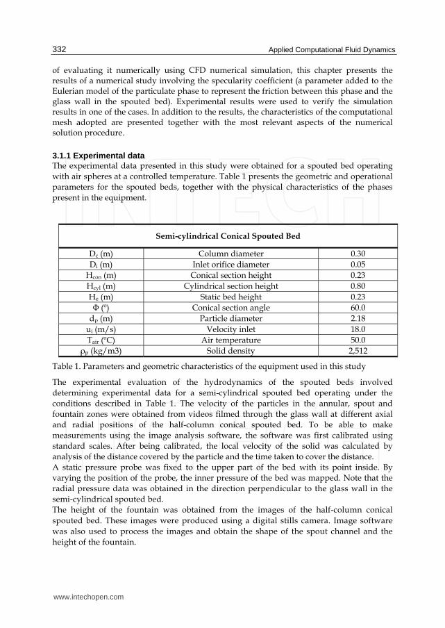
3.1.1 Experimental data The experimental data presented in this study were obtained for a spouted bed operating
with air spheres at a controlled temperature. Table 1 presents the geometric and operational
parameters for the spouted beds, together with the physical characteristics of the phases
present in the equipment.
Semi-cylindrical Conical Spouted Bed
Dc (m) Column diameter 0.30
Di (m) Inlet orifice diameter 0.05
Hcon (m) Conical section height 0.23
Hcyl (m) Cylindrical section height 0.80
He (m) Static bed height 0.23
Φ (º) Conical section angle 60.0
dp (m) Particle diameter 2.18
ui (m/s) Velocity inlet 18.0
Tair (ºC) Air temperature 50.0
ρp (kg/m3) Solid density 2,512
Table 1. Parameters and geometric characteristics of the equipment used in this study
The experimental evaluation of the hydrodynamics of the spouted beds involved
determining experimental data for a semi-cylindrical spouted bed operating under the
conditions described in Table 1. The velocity of the particles in the annular, spout and
fountain zones were obtained from videos filmed through the glass wall at different axial
and radial positions of the half-column conical spouted bed. To be able to make
measurements using the image analysis software, the software was first calibrated using
standard scales. After being calibrated, the local velocity of the solid was calculated by
analysis of the distance covered by the particle and the time taken to cover the distance.
A static pressure probe was fixed to the upper part of the bed with its point inside. By
varying the position of the probe, the inner pressure of the bed was mapped. Note that the
radial pressure data was obtained in the direction perpendicular to the glass wall in the
semi-cylindrical spouted bed.
The height of the fountain was obtained from the images of the half-column conical
spouted bed. These images were produced using a digital stills camera. Image software
was also used to process the images and obtain the shape of the spout channel and the
height of the fountain.
www.intechopen.com

Use of Fluid Dynamic Simulation to Improve the Design of Spouted Beds
333
3.2 Computational mesh and numerical procedure 3.2.1 Computational mesh The simulations were conducted using a three-dimensional mesh containing a symmetry plane to divide the domain. GAMBIT 2.13 software was used to generate the mesh. The spacing between nodes adopted was 5.0 mm, increasing gradually towards the outlet zone, where a spacing of 1.0 cm was adopted. The mesh used tetrahedral cells, reaching a mesh with 128,830 cells. Fig. 2 is a diagram of the mesh used in this part of the study.
Fig. 2. Computational mesh
Table 2 gives the general characteristics adopted for the construction of the computational mesh illustrated in Figure 2. Further information on cell geometry and meshing schemes can be found in Fluent (2006).
Computational mesh caracteristics
Minimum cell volume 3.67x10⁻⁹ m3
Maximum cell volume 1.04x10⁻⁶ m3
Total number of cells 128,830
Number of nodes: 25,596
Face meshing scheme
Inlet tube faces: TRI- PAVE1 Cone faces: TRI- PAVE
Cylinder faces: TRI- PAVE Intersection faces: TRI- PAVE
Volume meshing scheme: Tube: TET/HYBRID- TGRID2 Cone: TET/HYBRID- TGRID
Cylinder: TET/HYBRID- TGRID
Cells with high asymmetry (>0.97) 0
Table 2. Characteristics of the computational mesh
1 TRI-PAVE: triangular elements / PAVE meshing scheme. 2 TET/HYBRID-TGRID: mainly tetrahedral elements; however, elements of other geometries may be
used if required / TGRID meshing scheme.
www.intechopen.com

Applied Computational Fluid Dynamics
334
3.2.2 Boundary conditions The following boundary conditions were applied in this study:
Fluid is injected at the system inlet in the axial direction at constant velocity. The condition of the inlet turbulence was obtained by the intensity and length scale method, using equations from the literature to calculate these parameters (I=4.36%; L=0.0022 m);
The outlet pressure is defined as being atmospheric pressure. For the outlet turbulence conditions, the turbulence intensity and length scale method was again employed, using equations in the literature to calculate these parameters (I=5.4%; L=0.012 m);
The yz plane was defined as the symmetry plane for both of the simulated systems.
In the xz plane (flat wall), the non-slip condition was used for the fluid mechanics of the fluid phase of the system (air). For the particulate phase, the specularity coefficient was defined (the effect of this parameter on the hydrodynamics of the system is tested in this part of the study);
At the bed walls, the non-slip condition was adopted for the fluid phase and the partial-slip condition for the solid phase (by means of the specularity coefficient).
Phase parameters used in the simulations are given in Table 3:
Parameter Description Value
αs Porosity of the static bed 0.41
ess Restitution coefficient 0.9
ρs (kg/m3) Density of the solid 2,512
ρf (kg/m3) Density of the fluid (air) 1.0
µ (Pa.s) Air viscosity 2.09x10⁻⁵
ds (m) Diameter of the solid 2.18x10⁻³
Θ Sphericity 1.0
Table 3. Parameters applied to the simulation
3.2.3 Numerical solution The numerical solution was obtained using the Fluent® 6.3.26 software. The SIMPLE algorithm for the coupled phase was applied to solve the equations of the discretized model. The second-order upwind discretization scheme was applied for the momentum conservation equations. Relaxation factors were selected with values between 0 and 0.4. As a transient regime simulation was used, the system was considered permanent after 8 s of simulated time, using the integration steps between 1.0x10⁻⁴ and 5.0x10⁻⁴ s.
3.3 Evaluation of the specularity coefficient The effect of the specularity coefficient on the simulation results of the hydrodynamics of the semi-cylindrical spouted bed was analyzed with four different coefficient values. Specularity value was changed for wall positions between 0.0, 0.05, 0.1 and 0.2; the simulated results in response to these changes were analyzed. Simulated results for static pressure were then compared with experimental data. In addition to the static pressure results, the solid volume fractions and the solid and fluid velocity profiles were also evaluated numerically and discussed in the context of the numerical simulation.
www.intechopen.com
Use of Fluid Dynamic Simulation to Improve the Design of Spouted Beds
335
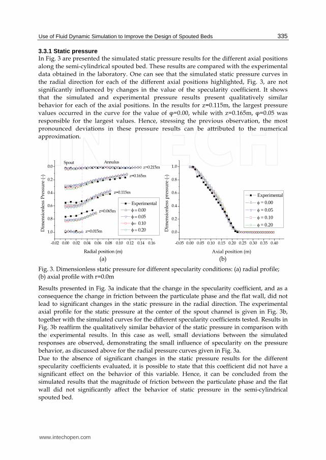
3.3.1 Static pressure In Fig. 3 are presented the simulated static pressure results for the different axial positions
along the semi-cylindrical spouted bed. These results are compared with the experimental
data obtained in the laboratory. One can see that the simulated static pressure curves in
the radial direction for each of the different axial positions highlighted, Fig. 3, are not
significantly influenced by changes in the value of the specularity coefficient. It shows
that the simulated and experimental pressure results present qualitatively similar
behavior for each of the axial positions. In the results for z=0.115m, the largest pressure
values occurred in the curve for the value of φ=0.00, while with z=0.165m, φ=0.05 was
responsible for the largest values. Hence, stressing the previous observation, the most
pronounced deviations in these pressure results can be attributed to the numerical
approximation.
-0.02 0.00 0.02 0.04 0.06 0.08 0.10 0.12 0.14 0.16
1.0
0.8
0.6
0.4
0.2
0.0Annulus
Experimental
0.00
0.05
0.10
0.20z=0.015m
z=0.065m
z=0.165m
z=0.115m
Dim
ensi
on
less
Pre
ssu
re (
-)
Radial position (m)
z=0.215mSpout
-0.05 0.00 0.05 0.10 0.15 0.20 0.25 0.30 0.35 0.40
0.0
0.2
0.4
0.6
0.8
1.0
Experimental
= 0.00
= 0.05
= 0.10
= 0.20
Dim
ensi
on
less
pre
ssu
re (
-)
Axial position (m) (a) (b)
Fig. 3. Dimensionless static pressure for different specularity conditions: (a) radial profile; (b) axial profile with r=0.0m
Results presented in Fig. 3a indicate that the change in the specularity coefficient, and as a
consequence the change in friction between the particulate phase and the flat wall, did not
lead to significant changes in the static pressure in the radial direction. The experimental
axial profile for the static pressure at the center of the spout channel is given in Fig. 3b,
together with the simulated curves for the different specularity coefficients tested. Results in
Fig. 3b reaffirm the qualitatively similar behavior of the static pressure in comparison with
the experimental results. In this case as well, small deviations between the simulated
responses are observed, demonstrating the small influence of specularity on the pressure
behavior, as discussed above for the radial pressure curves given in Fig. 3a.
Due to the absence of significant changes in the static pressure results for the different
specularity coefficients evaluated, it is possible to state that this coefficient did not have a
significant effect on the behavior of this variable. Hence, it can be concluded from the
simulated results that the magnitude of friction between the particulate phase and the flat
wall did not significantly affect the behavior of static pressure in the semi-cylindrical
spouted bed.
www.intechopen.com
Applied Computational Fluid Dynamics
336
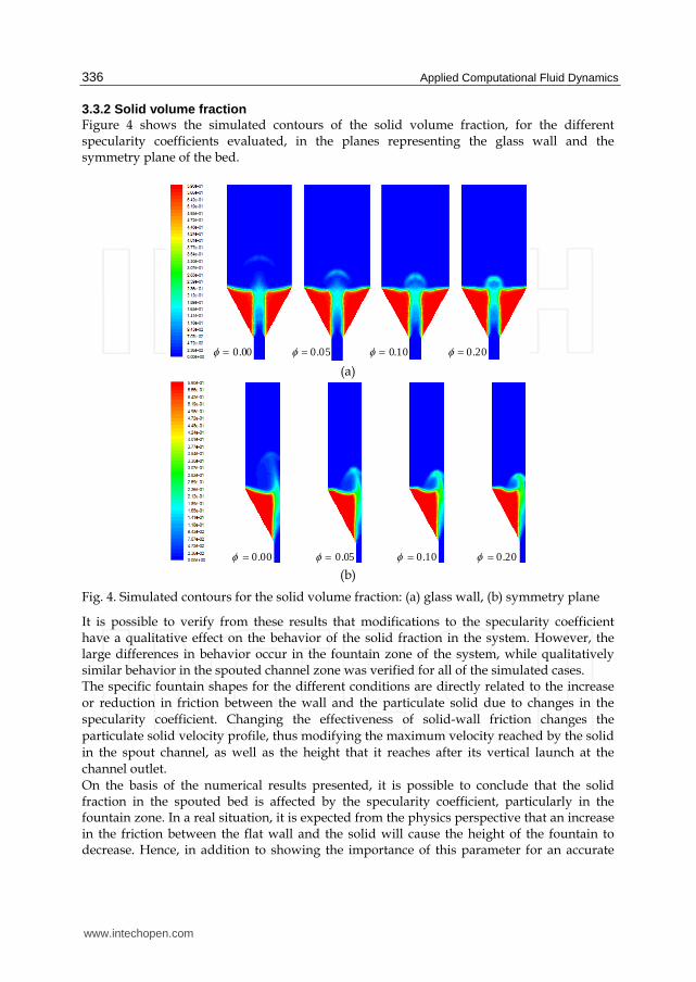
3.3.2 Solid volume fraction Figure 4 shows the simulated contours of the solid volume fraction, for the different specularity coefficients evaluated, in the planes representing the glass wall and the symmetry plane of the bed.
00.0 05.0 100. 200.
(a)
00.0 05.0 100. 200. (b)
Fig. 4. Simulated contours for the solid volume fraction: (a) glass wall, (b) symmetry plane
It is possible to verify from these results that modifications to the specularity coefficient have a qualitative effect on the behavior of the solid fraction in the system. However, the large differences in behavior occur in the fountain zone of the system, while qualitatively similar behavior in the spouted channel zone was verified for all of the simulated cases. The specific fountain shapes for the different conditions are directly related to the increase
or reduction in friction between the wall and the particulate solid due to changes in the
specularity coefficient. Changing the effectiveness of solid-wall friction changes the
particulate solid velocity profile, thus modifying the maximum velocity reached by the solid
in the spout channel, as well as the height that it reaches after its vertical launch at the
channel outlet.
On the basis of the numerical results presented, it is possible to conclude that the solid fraction in the spouted bed is affected by the specularity coefficient, particularly in the fountain zone. In a real situation, it is expected from the physics perspective that an increase in the friction between the flat wall and the solid will cause the height of the fountain to decrease. Hence, in addition to showing the importance of this parameter for an accurate
www.intechopen.com

Use of Fluid Dynamic Simulation to Improve the Design of Spouted Beds
337
representation of the behavior of the solid fraction in the bed, the results presented here prove, qualitatively, the effectiveness of including the specularity coefficient in the mathematical model for the hydrodynamics of the spouted bed.
3.3.3 Velocity of the solid phase and fluid phase Figure 5 shows the simulated velocity results for the particulate phase at the center of the spout channel along the axial direction. The qualitative similarity between the curves is verified by this figure, despite their quantitatively different behavior.
0.00 0.05 0.10 0.15 0.20 0.25 0.30 0.35 0.40
0.00
0.02
0.04
0.06
0.08
0.10
Dim
ensi
on
less
so
lid
vel
oci
ty (
-)
Axial position (m)
= 0.00 = 0.05 = 0.10 = 0.20
0.00 0.05 0.10 0.15 0.20 0.25 0.30 0.35 0.40 0.45 0.50
0.0
0.2
0.4
0.6
0.8
1.0
1.2
1.4 = 0.00 = 0.05 = 0.10 = 0.20
Dim
ensi
on
less
air
vel
oci
ty (
-)
Axial position (m)
Fountain
(a) (b)
Fig. 5. Dimensionless velocity at the center of the spout channel in the axial direction: (a) particulate phase, (b) fluid phase.
Analysis of the shape of the curves given in Figure 5 shows that the maximum velocity
achieved by the solid was inversely proportional to the increase in the value of the
specularity coefficient. As previously discussed, the increase in the specularity coefficient
reflects an increase in the effectiveness of the friction between the particulate phase and the
flat wall, which in turn tends to reduce the velocity of the contacting solid. Comparing the
curve for =0.00 with the other curves, it is possible to see that it has a region of practically
constant velocity for intermediate spout channel positions. When the specularity coefficient
was included, even at its smallest value, this tendency was not observed. It should be noted
that this region of velocity with a flat profile is not found in experimental results present in
the literature, which is a good indication of the need to include the specularity coefficient in
the system model. Figure 5b shows the simulated results for the velocity of the fluid phase at the center of the spout channel along the axial direction for different specularity coefficients. These results show that the specularity coefficient does not exert a significant influence on the behavior of the velocity of the fluid phase. Figure 5b also shows that the velocity of the fluid phase was not directly affected by the change in friction between the particulate phase and the flat wall. Hence, lower velocities in the particulate phase in the wall zone do not cause significant changes in the behavior of the velocity of the fluid phase. In the fountain zone, greater differences were seen between the curves for each of the situations evaluated. These differences must be due to the specific shape of the fountain that was investigated for each
www.intechopen.com
Applied Computational Fluid Dynamics
338
condition as it interfered with the distribution of air in this zone and caused the largest deviations found. From the numerical study presented it is possible to observe the importance of the effect of friction between the flat wall and the particulate phase. Here, this effect was incorpored by the inclusion of the specularity coefficient in the hydrodynamic model for the spouted bed. As the specularity coefficient is one way to represent this effect, its careful evaluation and determination is fundamental to obtain quantitatively representative results.
4. Advances in CFD applied to spouted beds
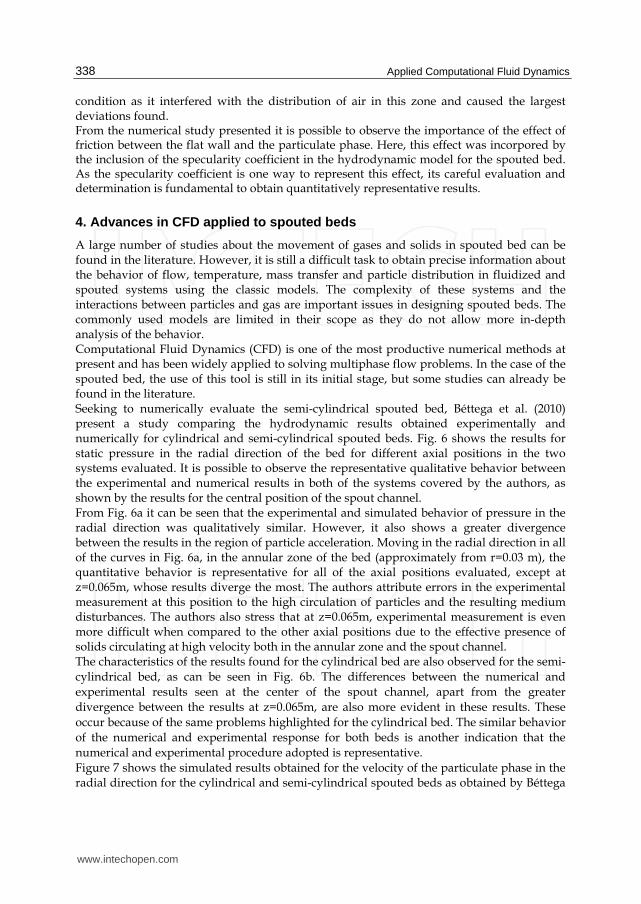
A large number of studies about the movement of gases and solids in spouted bed can be found in the literature. However, it is still a difficult task to obtain precise information about the behavior of flow, temperature, mass transfer and particle distribution in fluidized and spouted systems using the classic models. The complexity of these systems and the interactions between particles and gas are important issues in designing spouted beds. The commonly used models are limited in their scope as they do not allow more in-depth analysis of the behavior. Computational Fluid Dynamics (CFD) is one of the most productive numerical methods at present and has been widely applied to solving multiphase flow problems. In the case of the spouted bed, the use of this tool is still in its initial stage, but some studies can already be found in the literature. Seeking to numerically evaluate the semi-cylindrical spouted bed, Béttega et al. (2010) present a study comparing the hydrodynamic results obtained experimentally and numerically for cylindrical and semi-cylindrical spouted beds. Fig. 6 shows the results for static pressure in the radial direction of the bed for different axial positions in the two systems evaluated. It is possible to observe the representative qualitative behavior between the experimental and numerical results in both of the systems covered by the authors, as shown by the results for the central position of the spout channel. From Fig. 6a it can be seen that the experimental and simulated behavior of pressure in the radial direction was qualitatively similar. However, it also shows a greater divergence between the results in the region of particle acceleration. Moving in the radial direction in all of the curves in Fig. 6a, in the annular zone of the bed (approximately from r=0.03 m), the quantitative behavior is representative for all of the axial positions evaluated, except at z=0.065m, whose results diverge the most. The authors attribute errors in the experimental measurement at this position to the high circulation of particles and the resulting medium disturbances. The authors also stress that at z=0.065m, experimental measurement is even more difficult when compared to the other axial positions due to the effective presence of solids circulating at high velocity both in the annular zone and the spout channel. The characteristics of the results found for the cylindrical bed are also observed for the semi-
cylindrical bed, as can be seen in Fig. 6b. The differences between the numerical and
experimental results seen at the center of the spout channel, apart from the greater
divergence between the results at z=0.065m, are also more evident in these results. These
occur because of the same problems highlighted for the cylindrical bed. The similar behavior
of the numerical and experimental response for both beds is another indication that the
numerical and experimental procedure adopted is representative.
Figure 7 shows the simulated results obtained for the velocity of the particulate phase in the radial direction for the cylindrical and semi-cylindrical spouted beds as obtained by Béttega
www.intechopen.com

Use of Fluid Dynamic Simulation to Improve the Design of Spouted Beds
339
et al (2010). Clear differences can be seen in the behavior of this variable for the two systems in this figure.
0.00 0.02 0.04 0.06 0.08 0.10 0.12 0.14
1.0
0.8
0.6
0.4
0.2
0.0Annulus
Dim
ensi
on
less
pre
ssu
re (
-)
Radial position (m)
z=0.015m - Exp
z=0.065m - Exp
z=0.115m - Exp
z=0.165m - Exp
z=0.215m - Exp
z=0.015m - Sim
z=0.065m - Sim
z=0.115m - Sim
z=0.165m - Sim
z=0.215m - Sim
Spout
0.00 0.02 0.04 0.06 0.08 0.10 0.12 0.14
1.0
0.8
0.6
0.4
0.2
0.0Annulus
Dim
ensi
on
less
pre
ssu
re (
-)Radial position (m)
z=0.015m - Exp
z=0.065m - Exp
z=0.115m - Exp
z=0.165m - Exp
z=0.215m - Exp
z=0.015m - Sim
z=0.065m - Sim
z=0.115m - Sim
z=0.165m - Sim
z=0.215m - Sim
Spout
(a) (b)
Fig. 6. Static pressure in the radial direction: (a) cylindrical bed, (b) semi-cylindrical bed
Quantitative and qualitative differences between the simulation results of both systems are
evident in Fig. 7, especially in the spout channel, whose velocity of the solid is greater. These
results indicate that the flat wall placed into the conventional spouted bed to produce the
semi-cylindrical configuration changes the behavior of the particulate phase close to the flat
wall significantly. From these results, using the simulated data, it is possible to reaffirm the
observation of He et al. (1994a). The authors observed experimentally that the flat wall
placed in the spouted bed caused additional friction to the system, provoking changes in the
behavior of the solid phase velocity. The qualitative comparison of the results for the
velocity of the solid obtained by He et al. (1994a) in conical-cylindrical spouted beds with
the numerical results obtained in this study indicates qualitatively similar responses and
that the simulation is representative.
0.14 0.12 0.10 0.08 0.06 0.04 0.02 0.00
0.0
0.5
1.0
1.5
2.0
2.5
0.00 0.02 0.04 0.06 0.08 0.10 0.12 0.14
Vel
oci
ty (
m/
s)Cylindrical
spout-annulus interface
Vel
oci
ty (
m/
s)
Radial position (m)
z=0.015m
z=0.065m
z=0.115m
z=0.165m
z=0.215m
Semi-cylindrical
z=0.015m
z=0.065m
z=0.115m
z=0.165m
z=0.215m
0.0
0.5
1.0
1.5
2.0
2.5
spout-annulus interface
Fig. 7. Velocity of the simulated particulate phase along the radial direction
www.intechopen.com
Applied Computational Fluid Dynamics
340
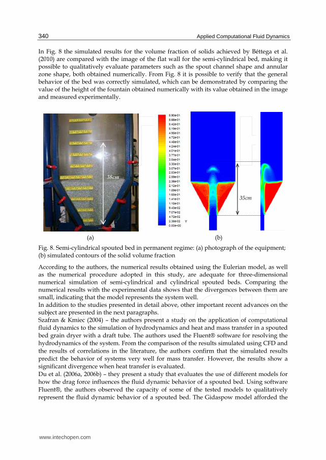
In Fig. 8 the simulated results for the volume fraction of solids achieved by Béttega et al. (2010) are compared with the image of the flat wall for the semi-cylindrical bed, making it possible to qualitatively evaluate parameters such as the spout channel shape and annular zone shape, both obtained numerically. From Fig. 8 it is possible to verify that the general behavior of the bed was correctly simulated, which can be demonstrated by comparing the value of the height of the fountain obtained numerically with its value obtained in the image and measured experimentally.
Fig. 8. Semi-cylindrical spouted bed in permanent regime: (a) photograph of the equipment; (b) simulated contours of the solid volume fraction
According to the authors, the numerical results obtained using the Eulerian model, as well as the numerical procedure adopted in this study, are adequate for three-dimensional numerical simulation of semi-cylindrical and cylindrical spouted beds. Comparing the numerical results with the experimental data shows that the divergences between them are small, indicating that the model represents the system well. In addition to the studies presented in detail above, other important recent advances on the subject are presented in the next paragraphs. Szafran & Kmiec (2004) – the authors present a study on the application of computational
fluid dynamics to the simulation of hydrodynamics and heat and mass transfer in a spouted
bed grain dryer with a draft tube. The authors used the Fluent® software for resolving the
hydrodynamics of the system. From the comparison of the results simulated using CFD and
the results of correlations in the literature, the authors confirm that the simulated results
predict the behavior of systems very well for mass transfer. However, the results show a
significant divergence when heat transfer is evaluated.
Du et al. (2006a, 2006b) – they present a study that evaluates the use of different models for
how the drag force influences the fluid dynamic behavior of a spouted bed. Using software
Fluent®, the authors observed the capacity of some of the tested models to qualitatively
represent the fluid dynamic behavior of a spouted bed. The Gidaspow model afforded the
38cm
35cm
(a) (b)
www.intechopen.com

Use of Fluid Dynamic Simulation to Improve the Design of Spouted Beds
341
best results in relation to the experimental data. Continuing this work, the authors presented
a new study evaluating the effect of drag, maximum packing, and restitution coefficient on
the fluid dynamics of the spouted bed of Du et al. (2006b). These studies allowed proposing
a new initial estimate of these important parameters to simulate a spouted bed, as well as
knowing their qualitative effects on numerical simulation.
Zhonghua & Mujumdar (2008) – using the Fluent® 6.2 commercial package, the authors
applied CFD to the numerical simulation of the behavior of spouted beds in two and three
dimensions based on experimental systems in the literature. To verify the results in two
dimensions, experimental data for particulate velocity presented in He et al. (1994a),
obtained in a conical-cylindrical bed with optical fiber sensors, were used. For the three-
dimensional bed, the parameters and experimental data presented by Link et al. (2005) were
used. These authors used image analysis to obtain velocity and porosity data for a
rectangular spouted bed. The behavior of the numerical results for both of the systems
satisfactorily described the behavior of the two cases evaluated. In the three-dimensional
case, the simulator was capable of capturing hydrodynamic perturbations in the equipment
that appeared as instabilities in the bed. Simulated pressure curves were also presented in
the study for the three-dimensional case analyzed. The authors verified that the pressure
behavior was affected by the instabilities present in the equipment.
Duarte et al. (2009) – this work presented CFD simulations of conical and conical-cylindrical
spouted beds using experimental data, from the literature and their own experimentation, to
verify the numerical results. This study presented numerical results for the characteristic
curve of the spouted bed and compared it directly to experimental results, thus confirming
their agreement. The minimal spouted flow for the conical cylindrical bed was also
numerically evaluated and compared with correlations from the literature, indicating the
capacity of the numerical tool to obtain a good approximation for this variable. The authors
also illustrated, with the contours of volumetric fraction of the solids, the evolution of the
spouted bed from static bed to spouted condition in both evaluated cases.
Béttega et al. (2009a) – they evaluated the problem of increase in scale of spouted beds using
numerical simulation. The software Fluent® was used to simulate the spouted beds in
different scales, respecting the non-dimensional parameters obtained from the work of He et
al. (1994a, 1994b) to ensure the conditions of geometric and dynamic similarity. They used
simulation to verify the capacity of the numerical tool to reproduce the increase in the scale
when the non-dimensional parameters are maintained. They numerically confirmed the
experimental observation that when these parameters are satisfied, a similar fluid dynamic
behavior of beds with different scales is ensured. They also evaluated the response of the
spouted bed to the increase in scale for the usual grain drying conditions, in which the
values of parameters such as density and viscosity of the fluid remained unchanged to
satisfy the scale relationships. In some of the analyzed cases, the numerical response
indicated the presence of instabilities for small scale alterations, as it is well known to occur
in spouted beds – a great difficulty in increasing scale.
Béttega et al. (2009b) – this work presented a three-dimensional simulation of a half-column conical spouted bed. The authors compared the simulation results for parameters such as the spouted channel format, fountain format and height, as well the surface of the annulus, with information generated from images based on an experiment carried out under the same conditions as those of simulation. The simulated particle velocity profiles were also evaluated from the experimental measures performed using a high speed camera, revealing
www.intechopen.com

Applied Computational Fluid Dynamics
342
a great coherence between both the numerical and experimental results. For the simulation, the authors neglected the friction between the wall and the particulate solid phase. The characteristic curve experimentally obtained is also presented. The numerical pressure was compared to the experimental value under the same conditions. Rosa and Freire (2009) – in this work the fluid dynamic behavior of a spouted bed with a draft tube inside and continuously feeded with particle from the bottom was studied through experimental data of static pressure, fountain height, and fluid mass flow in the annulus, as well as using the computational fluid dynamics. The authors observed that the two-dimensional CFD model based on the Euler-Euler approach was successfully applied to describe the fluid dynamic behavior of this system. By comparing experimental and numerical data, the authors highlight the possibility of identifying the different regions of the equipment based on the fluid dynamic data.
5. Conclusions
From the numerical study presented in this chapter it was possible to identify and evaluate, in a qualitative way, the importance of the effect of friction between the flat wall and the particulate phase, represented by the inclusion of the specularity coefficient in the hydrodynamic model for the spouted bed. It was verified by these simulated results that this coefficient shows a strong influence on the behavior of the particulate phase in the semi-cylindrical spouted bed. However, its effect on the static pressure, the velocity of the fluid phase in the bed and on the solid fraction behavior in the spout channel is not very pronounced. Hence, it is possible to conclude that correctly determining the friction between the flat wall and the particulate phase is extremely important for an effective simulation of the hydrodynamics of the semi-cylindrical spouted bed. As the specularity coefficient is one way to represent this effect, its careful evaluation and determination is fundamental to obtain quantitatively representative results.
6. References
Béttega, R., Corrêa, R. G. & Freire, J. T. (2009a). Scale-up Study of Spouted Beds Using Computational Fluid Dynamics. Canadian Journal of Chemical Engineering, Vol.87, No.2 (April 2009), pp. 193-203, ISSN 0008-4034.
Béttega, R., Almeida, A. R. F., Corrêa, R. G. & Freire, J. T. (2009b). CFD Evaluation of a Semi-cylindrical Spouted Bed: Numerical Simulation and Experimental Verification, Canadian Journal of Chemical Engineering, Vol.87, No.2 (April 2009), pp. 177-184, ISSN 0008.
Béttega, R., Corrêa, R. G. & Freire, J. T. (2010). Three-Dimensional Numerical Simulation of Semi-Cylindrical and Cylindrical Spouted Bed Hydrodynamics. Drying Technology, Vol.28, No.11, (November 2010), pp. 1266—1276, ISSN 0737-3937.
Chapman, S. & Cowling, T. G. (1991). The Mathematical Theory of Non-Uniform Gases, Cambridge University Press, ISBN 052140844X, New York, USA.
Du, W., Bao, X., Xu, J. & Wei, W. (2006a). Computational Fluid Dynamics (CFD) Modeling of Spouted Bed: Assessment of Drag Coefficient Correlations. Chemical Engineering Science, Vol.61, No.5, (March 2006), pp. 1401-1420, ISSN 0009-2509.
www.intechopen.com

Use of Fluid Dynamic Simulation to Improve the Design of Spouted Beds
343
Du, W., Bao, X., Xu, J. & Wei, W. (2006b). Computational Fluid Dynamics (CFD) Modeling of Spouted Bed: Influence of Stress, Maximum Packing Limit and Coefficient of Restitution of Particles. Chemical Engineering Science, Vol.61, No.14, (July 2006), pp. 4558-4570, ISSN 0009-2509.
Duarte, C. R., Olazar, M., Murata, V.V. & Barrozo, M.A.S. (2009). Numerical Simulation and Experimental Study of Fluid–particle Flows in a Spouted Bed. Powder Technology, vol. 188, No.3, (January 2009), pp. 195–205, ISSN: 0032-5910.
Ergun, S. (1952). Fluid Flow Through Packed Columns. Chemical Engineering Progress, Vol.48, No.2, (February 1952), pp. 89–94.
Fluent, (2006). Fluent 6.3 User's Guide. Fluent Inc., Lebanon, New Hampshire, USA. Gidaspow, D., Bezburuah, R. & Ding, J.(1992). Hydrodynamics of Circulating Fluidized
beds, Kinetic Theory Approach. In: Fluidization VII – Proceedings of the 7th Engineering Foundation Conference on Fluidization, pp. 75-82, Brisbane, Australia.
He, Y. L., Lim, C. J., Grace, J. R., Zhu, J. X. & Qin, S. Z. (1994b). Measurements of Voidage Profiles in Spouted Beds. Canadian Journal of Chemical Engineering, Vol.72, No.2, (April 1994), pp. 229-234, ISSN 0008-4034.
He, Y. L., Qin, S. Z., Lim, C. J. & Grace, J. R. (1994a). Particle Velocity Profiles and Solid Flow Patterns in Spouted Beds. Canadian Journal of Chemical Engineering, Vol.72, No.4, (August 1994), pp. 561-568, ISSN 0008-4034.
Johnson, P.C & Jackson, R. (1987). Frictional-collisional Constitutive Relations for Granular Materials with Application to Plane Shearing. Journal of Fluid Mechanics, Vol.176, (March 1987), pp. 67-93, ISSN 0022-1120.
Lefroy, G. A. & Davidson J. F. (1969). The Mechanics of Spouted Beds. Trans. Instn. Chem Eng., Vol.47, pp. 120-128.
Link, J. M., Cuypers, L. A., Deen, N. G. & Kuipers, J. A. M. (2005). Flow Regimes in a Spout-Fluid Bed: A Combinated Experimental and Simulation Study. Chemical Engineering Science, Vol.60, No.13, (July 2005), pp. 3425-3442, ISSN 0009-2509.
Lun, C. K. K., Savage, S. B & Jeffrey, D.J. (1984). Kinetics Theories for Granular Flow: Inelastic Particles in Flow and Slightly Inelastic Particles in General Flow Field. Journal of Fluid Mechanics, Vol.140, (March 1984), pp. 223-256, ISSN 0022-1120.
Mathur, K. B. & Gishler, P. E. (1955). A Technique for Contacting Gases with Coarse Solid Particles. AIChE Journal, Vol.1, No.2, (June 1955), pp. 157-168, ISSN 1547-5905.
Ocone, R., Sundaresan, S. & Jackson, R. (1993). Gas-particle Flow in a Duct of Arbitrary Inclination with Particle-particle Interaction. AIChE Journal, Vol.39, No.8, (August 1993), pp. 1261-1271, ISSN 1547-5905.
Ogawa, S., Umemura, A. & Oshima, N. (1980). On the Equation of Fully Fluidized Granular Materials. Journal of Applied Mathematics and Physics, Vol.31, No. 4, (July 1980), pp. 483-493, ISSN 0044-2275.
Rosa, C.A. & Freire, J.T. (2009). Fluid Dynamics Analysis of a Draft-tube Continuous Spouted Bed with Particles Bottom Feed Using CFD. Industrial &. Engineering Chemistry. Research, Vol.48, No.16, (August 2009), pp. 7813-7820, ISSN 0888-5885.
Schaeffer, D.G. (1987). Instability in the Evolution Equations Describing Incompressible Granular Flow. Journal of Differencial Equations, Vol.66, (January 1987), pp. 19-50, ISSN: 0022-0396.
www.intechopen.com

Applied Computational Fluid Dynamics
344
Szafran, R. G. & Kmiec, A. (2004). CFD Modeling of Heat and Mass Transfer in a Spouted Bed Dryer. Industrial & Engineering Chemstry Research, Vol.43, No.4, (January 2004), pp. 1113-1124, ISSN 0888-5885.
Wen, C.Y. & Yu, Y.H. (1966). Mechanics of Fluidization. Chem. Eng. Prog. Symp. Series, Vol. 62, pp. 100-111.
Zhonghua, W. & Mujumdar, A. S. (2008). CFD Modeling of the Gas-Particle Flow Behavior in Spouted Beds. Powder Technology, Vol.183, No.2, (April 2008), pp. 260-272, ISSN: 0032-5910.
www.intechopen.com

Applied Computational Fluid DynamicsEdited by Prof. Hyoung Woo Oh
ISBN 978-953-51-0271-7Hard cover, 344 pagesPublisher InTechPublished online 14, March, 2012Published in print edition March, 2012
InTech EuropeUniversity Campus STeP Ri Slavka Krautzeka 83/A 51000 Rijeka, Croatia Phone: +385 (51) 770 447 Fax: +385 (51) 686 166www.intechopen.com
InTech ChinaUnit 405, Office Block, Hotel Equatorial Shanghai No.65, Yan An Road (West), Shanghai, 200040, China
Phone: +86-21-62489820 Fax: +86-21-62489821
This book is served as a reference text to meet the needs of advanced scientists and research engineers whoseek for their own computational fluid dynamics (CFD) skills to solve a variety of fluid flow problems. KeyFeatures: - Flow Modeling in Sedimentation Tank, - Greenhouse Environment, - Hypersonic Aerodynamics, -Cooling Systems Design, - Photochemical Reaction Engineering, - Atmospheric Reentry Problem, - Fluid-Structure Interaction (FSI), - Atomization, - Hydraulic Component Design, - Air Conditioning System, -Industrial Applications of CFD
How to referenceIn order to correctly reference this scholarly work, feel free to copy and paste the following:
Rodrigo Béttega, Ronaldo Guimarães Corrêa and José Teixeira Freire (2012). Use of Fluid DynamicSimulation to Improve the Design of Spouted Beds, Applied Computational Fluid Dynamics, Prof. Hyoung WooOh (Ed.), ISBN: 978-953-51-0271-7, InTech, Available from: http://www.intechopen.com/books/applied-computational-fluid-dynamics/use-of-fluid-dynamic-simulation-to-improve-the-design-of-spouted-beds
Related Documents