22/09/2013 Page 1 WF’s 703n external antenna modification The Chinese market TP-Link703n 150n USB router is a robust, small, low power and reliable router. It may be flashed from its Chinese firmware to TP-Links 3020 English firmware or DD-WRT or OpenWRT or OpenWRT based firmwares like Gargoyle and ROOter etc. It is powered by 5 volts and supports a single 100Mb LAN/WAN port, a USB 2.0 port and a micro USB port for power connection. The 703n has an internal inverted F ¼ wave length PCB etched antenna. There is no external antenna connection. This tutorial documents the necessary modifications to add a standard RP-SMA antenna socket to the 703n. The inspiration for this modification largely comes from these two blog articles: http://blagg.tadkom.net/2012/09/01/wr-703n-external-antenna-mod-diy/ See comments by luno http://blagg.tadkom.net/2012/09/15/better-wr703n-antenna-mod/ See comments by Diarmaid Ó Cualain The 703n’s internal PCB etched antenna is an inverted ¼ wave dipole fed at the 50 ohm impedance point by the PCB tracks. C29, C31 and C32 are a Pi impedance matching circuit. Essentials of the modification

703n External WIFI Antenna Modification
Oct 22, 2015
Modify a pocket 703n router to add an external WIFI antenna.
Test reports and How To
Test reports and How To
Welcome message from author
This document is posted to help you gain knowledge. Please leave a comment to let me know what you think about it! Share it to your friends and learn new things together.
Transcript

22/09/2013 Page 1
WF’s 703n external antenna modification
The Chinese market TP-Link703n 150n USB router is a robust, small, low power and reliable router. It
may be flashed from its Chinese firmware to TP-Links 3020 English firmware or DD-WRT or
OpenWRT or OpenWRT based firmwares like Gargoyle and ROOter etc. It is powered by 5 volts and
supports a single 100Mb LAN/WAN port, a USB 2.0 port and a micro USB port for power connection.
The 703n has an internal inverted F ¼ wave length PCB etched antenna. There is no external antenna
connection. This tutorial documents the necessary modifications to add a standard RP-SMA antenna
socket to the 703n. The inspiration for this modification largely comes from these two blog articles:
http://blagg.tadkom.net/2012/09/01/wr-703n-external-antenna-mod-diy/ See comments by luno
http://blagg.tadkom.net/2012/09/15/better-wr703n-antenna-mod/ See comments by Diarmaid Ó Cualain
The 703n’s internal PCB etched antenna is an inverted ¼ wave dipole fed at the 50 ohm impedance point by the PCB tracks. C29, C31 and C32 are a Pi impedance matching circuit.
Essentials of the modification

22/09/2013 Page 2
The PCB tracks are first cut at the on board antenna feed points. The copper track is tinned and the
coaxial cable with RP-SMA connector, soldered to these two points.
Suitable coaxial cable and RP-SMA connectors are readily available. Google “u fl/ IPX to RP SMA male
pigtail cable”. A standard 5/8 wave length router antenna from a Tiny Dovado was used.
I used a basic cheap motorised engraving tool to grind the break in the two tracks.
Cut off the u.fl connector and trim the coaxial cable length accordingly. At 2.4Ghz this cable is quite lossy, so keep it as short as practicable.
The inverted F antenna took to solder like a duck to water as it was not varnished. It was pretty straightforward apart from the scale of things inside the magic little blue box. A jewellers eye piece or similar is essential.
My soldering weapon of choice is an ancient low voltage temperature controlled Weller with a fine tip. Ensure you keep the temperature low, so that you don’t damage and lift the tracks.
I think I have chosen the best location for the antenna, which is adjacent to the existing internal
antenna, but there are a number of options.
There is an amazing reverse engineered circuit diagram of the 703n available on the web:
http://squonk42.github.io/TL-WR703N/
A snap of the WIFI section and the modification follows:

22/09/2013 Page 3
A view of the antenna installation and how to gain entry to the 703n

22/09/2013 Page 4
The finished product
22/09/2013 Page 5
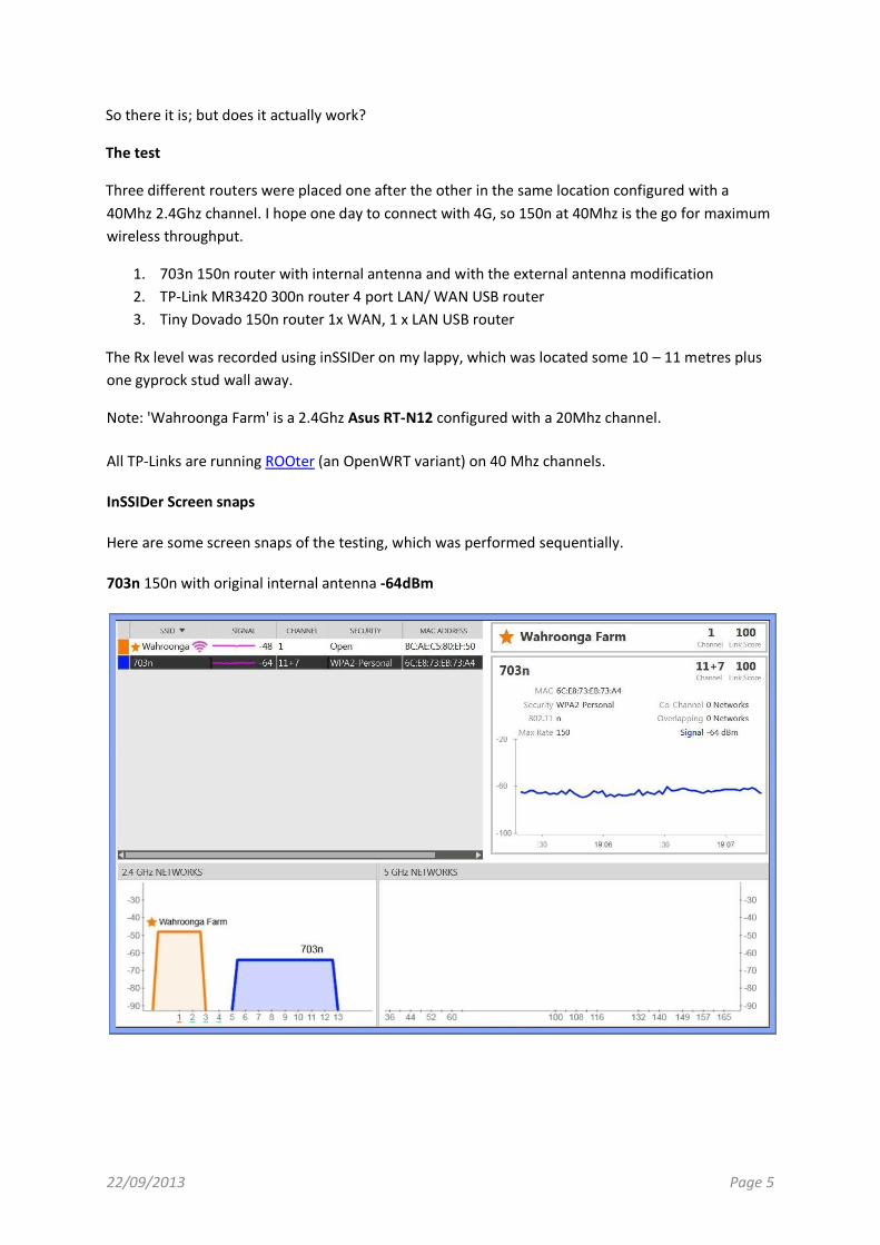
So there it is; but does it actually work?
The test
Three different routers were placed one after the other in the same location configured with a
40Mhz 2.4Ghz channel. I hope one day to connect with 4G, so 150n at 40Mhz is the go for maximum
wireless throughput.
1. 703n 150n router with internal antenna and with the external antenna modification
2. TP-Link MR3420 300n router 4 port LAN/ WAN USB router
3. Tiny Dovado 150n router 1x WAN, 1 x LAN USB router
The Rx level was recorded using inSSIDer on my lappy, which was located some 10 – 11 metres plus
one gyprock stud wall away.
Note: 'Wahroonga Farm' is a 2.4Ghz Asus RT-N12 configured with a 20Mhz channel.
All TP-Links are running ROOter (an OpenWRT variant) on 40 Mhz channels.
InSSIDer Screen snaps
Here are some screen snaps of the testing, which was performed sequentially.
703n 150n with original internal antenna -64dBm

22/09/2013 Page 6
MR3420 V1 300n with 2 x external antenna -48dBm
Tiny Dovado 150n with 1 x external antenna -53dBm

22/09/2013 Page 7
Modified 703n 150n with 1 x external antenna -47dBm
The 703n is the 'loudest' of the three. It looks like it's working well.
Above is a test with the laptop outside the house (lot’s of masonry walls) about 40m from the 703n.
You can see the trace as I wandered outside. It connected and browsed the web on -80dBm with a
connection speed of 5.5 – 11.0 Mbps. It’s a harsh test for a 40Mhz channel.

22/09/2013 Page 8
As another test of the 703n’s signal level, I surveyed the external surrounds of the house with an
Android Samsung S2 running inSSIDer.
The 40Mhz 703n signal was consistently within a few db of the 20Mhz channel Asus RT-N12 (it was
both higher and lower), wherever I measured.
Happy modifying
WF
PS This is an approximately true size view.
PPS Forums to discuss this modification.
https://forum.openwrt.org/viewtopic.php?pid=214338
http://forums.whirlpool.net.au/forum-replies.cfm?t=2159920
Related Documents