1 RECRYSTALLIZATION IN METALS FLORENT LEFEVRE-SCHLICK and DAVID EMBURY Department of Materials Science and Engineering McMaster University, Hamilton, ON, Canada

702 florent lefevre-schlick_november_2005
Aug 07, 2015
Welcome message from author
This document is posted to help you gain knowledge. Please leave a comment to let me know what you think about it! Share it to your friends and learn new things together.
Transcript
1
RECRYSTALLIZATION IN METALS
FLORENT LEFEVRE-SCHLICK and DAVID EMBURY
Department of Materials Science and EngineeringMcMaster University, Hamilton, ON, Canada
2
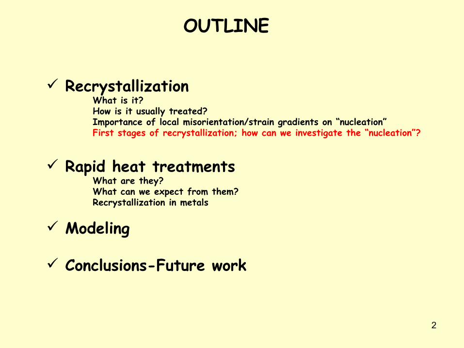
OUTLINE
RecrystallizationWhat is it?How is it usually treated?Importance of local misorientation/strain gradients on “nucleation”First stages of recrystallization; how can we investigate the “nucleation”?
Rapid heat treatmentsWhat are they?What can we expect from them?Recrystallization in metals
Modeling
Conclusions-Future work
3
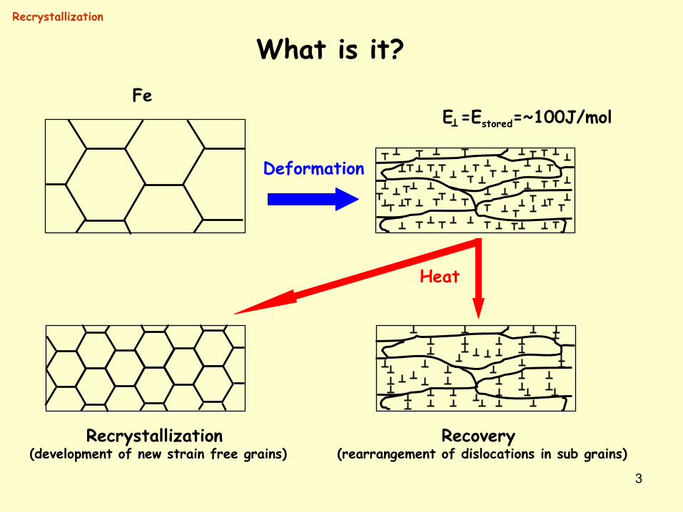
What is it?Fe
E =Estored=~100J/mol
Deformation
Heat
Recovery (rearrangement of dislocations in sub grains)
Recrystallization (development of new strain free grains)
Recrystallization
4
Recrystallization
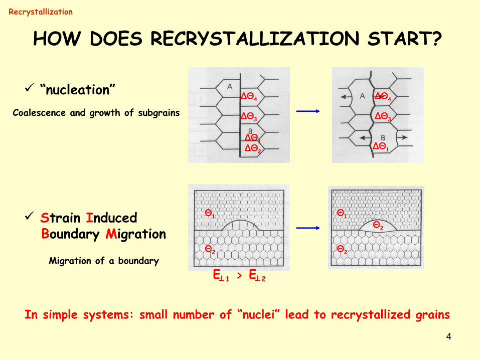
HOW DOES RECRYSTALLIZATION START?
“nucleation”
Strain Induced Boundary Migration
∆Θ1∆Θ2
∆Θ3
∆Θ4
∆Θ1
∆Θ3
∆Θ4
Θ1
Θ2
Θ1
Θ2
Θ2
E 1 E 2>
Coalescence and growth of subgrains
Migration of a boundary
In simple systems: small number of “nuclei” lead to recrystallized grains
5
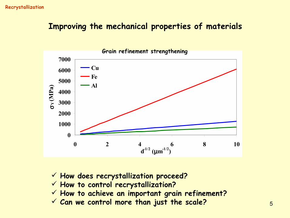
Improving the mechanical properties of materials
How does recrystallization proceed? How to control recrystallization? How to achieve an important grain refinement? Can we control more than just the scale?
0
1000
2000
3000
4000
5000
6000
7000
0 2 4 6 8 10d-1/2 (µm-1/2)
σY (
MPa
)
CuFeAl
Recrystallization
Grain refinement strengthening
6
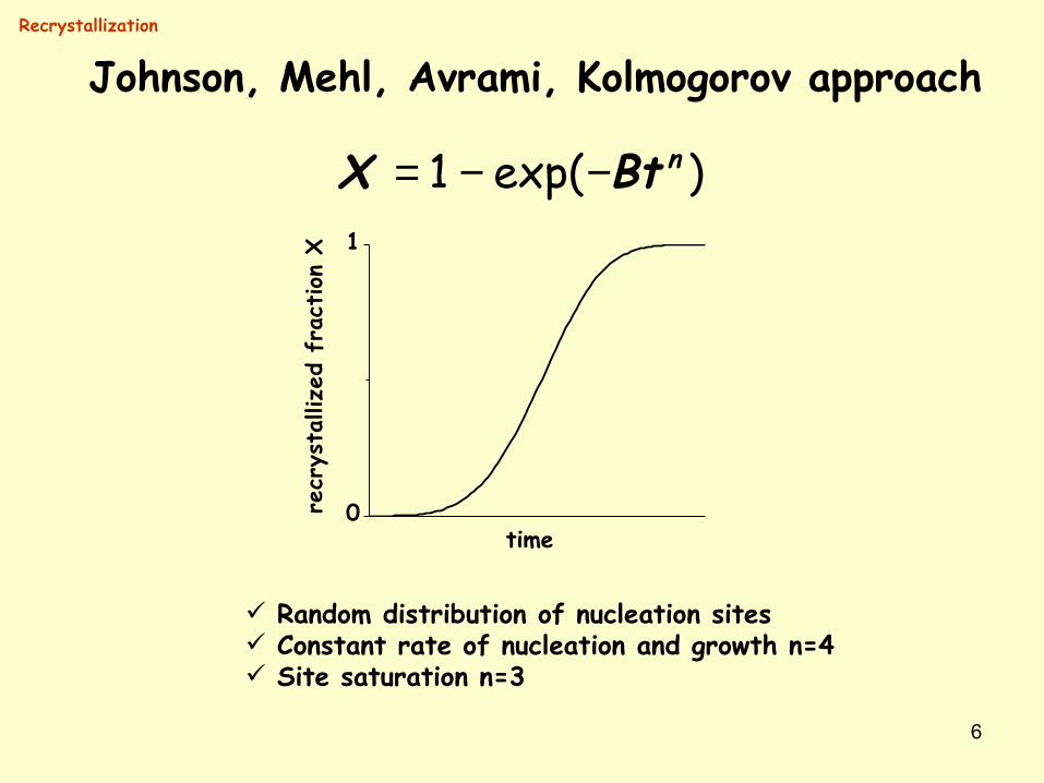
Johnson, Mehl, Avrami, Kolmogorov approach
1 exp( )nX Bt= − −
0
1
recr
ysta
llize
d fr
action
X
time
Random distribution of nucleation sites Constant rate of nucleation and growth n=4 Site saturation n=3
Recrystallization
7
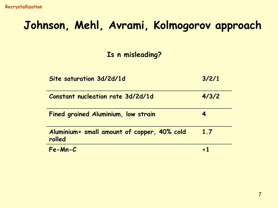
Johnson, Mehl, Avrami, Kolmogorov approach
Recrystallization
Is n misleading?
<1Fe-Mn-C
1.7Aluminium+ small amount of copper, 40% cold rolled
4Fined grained Aluminium, low strain
4/3/2Constant nucleation rate 3d/2d/1d
3/2/1Site saturation 3d/2d/1d
8
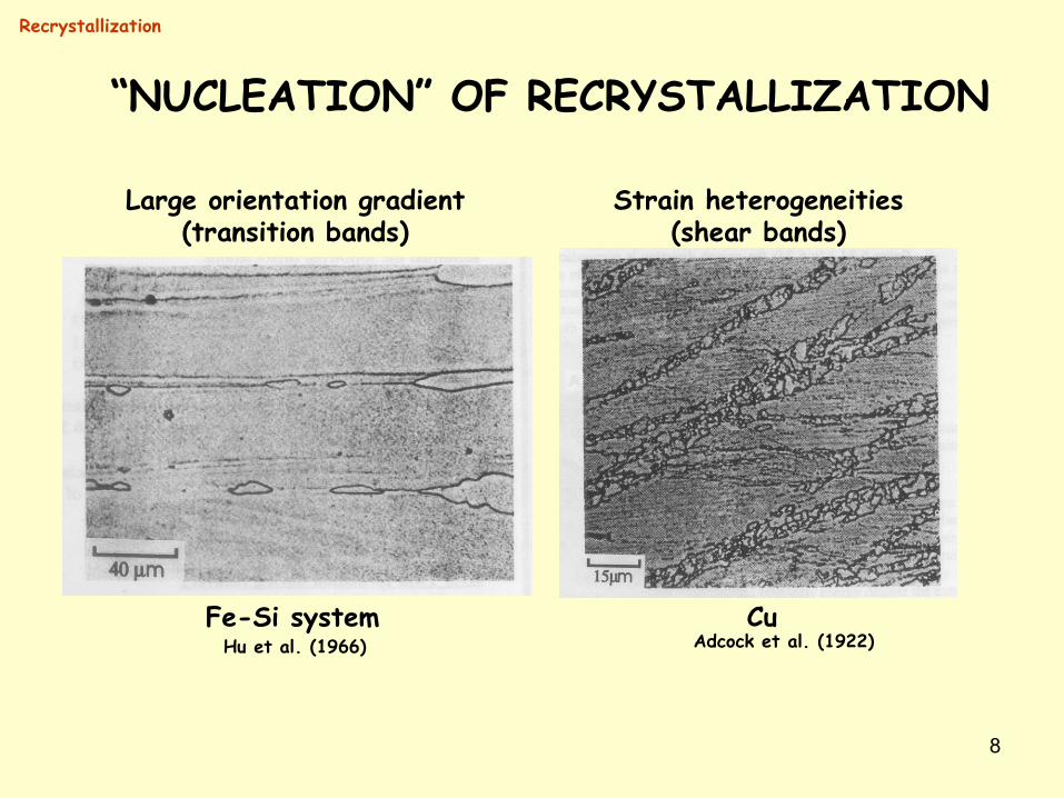
“NUCLEATION” OF RECRYSTALLIZATION
Recrystallization
Hu et al. (1966) Adcock et al. (1922)
Large orientation gradient(transition bands)
Strain heterogeneities(shear bands)
Fe-Si system Cu
9
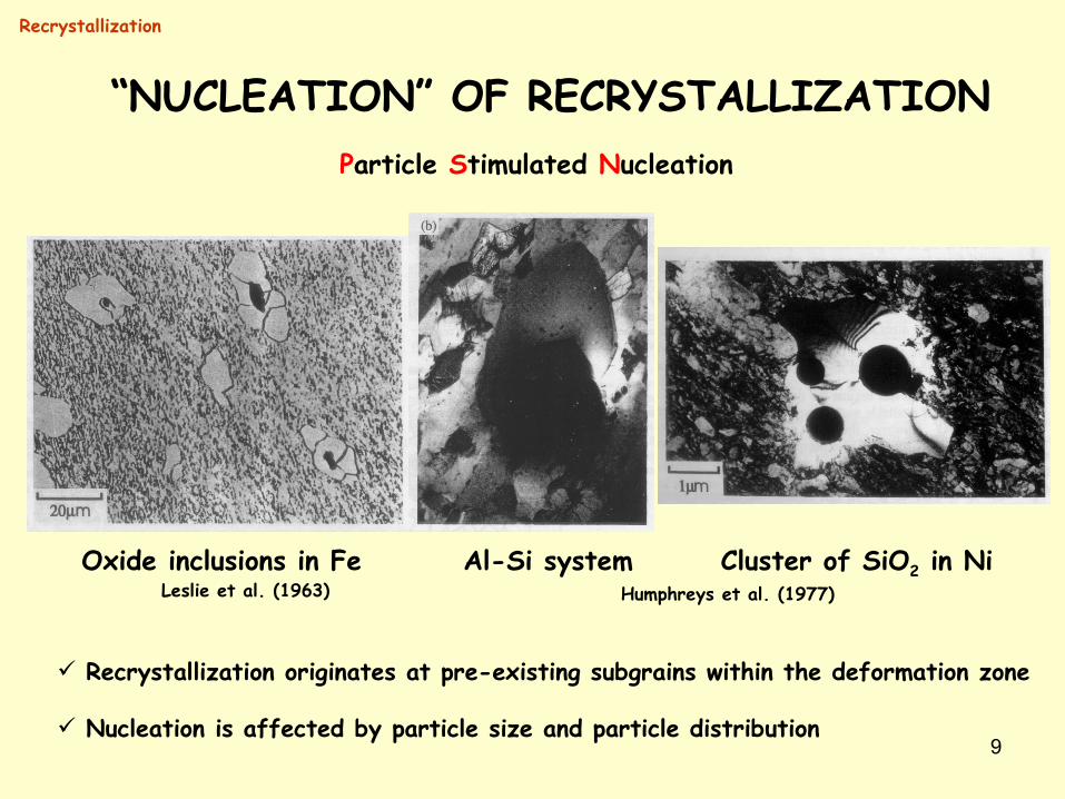
Particle Stimulated Nucleation
Leslie et al. (1963) Humphreys et al. (1977)Oxide inclusions in Fe Al-Si system Cluster of SiO2 in Ni
Recrystallization originates at pre-existing subgrains within the deformation zone
Nucleation is affected by particle size and particle distribution
“NUCLEATION” OF RECRYSTALLIZATION
Recrystallization
10
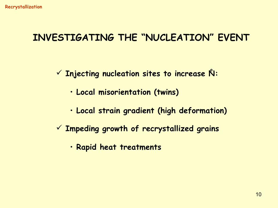
INVESTIGATING THE “NUCLEATION” EVENT
Injecting nucleation sites to increase N:
• Local misorientation (twins)
• Local strain gradient (high deformation)
Recrystallization
o
Impeding growth of recrystallized grains
• Rapid heat treatments
11
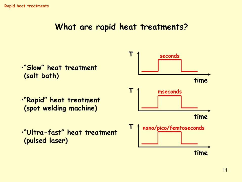
What are rapid heat treatments?
T
time
•“Slow” heat treatment (salt bath)
•“Rapid” heat treatment (spot welding machine)
•“Ultra-fast” heat treatment (pulsed laser)
T
timeT
time
seconds
mseconds
nano/pico/femtoseconds
Rapid heat treatments
12
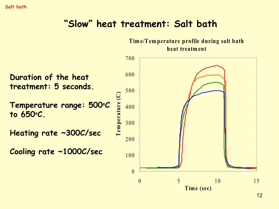
“Slow” heat treatment: Salt bathTim e/Tem perature profile during salt bath
heat treatm ent
0
100
200
300
400
500
600
700
0 5 10 15Time (sec)
Tem
pera
ture
(C)
Duration of the heat treatment: 5 seconds.
Temperature range: 500oC to 650oC.
Heating rate ~300C/sec
Cooling rate ~1000C/sec
Salt bath
13
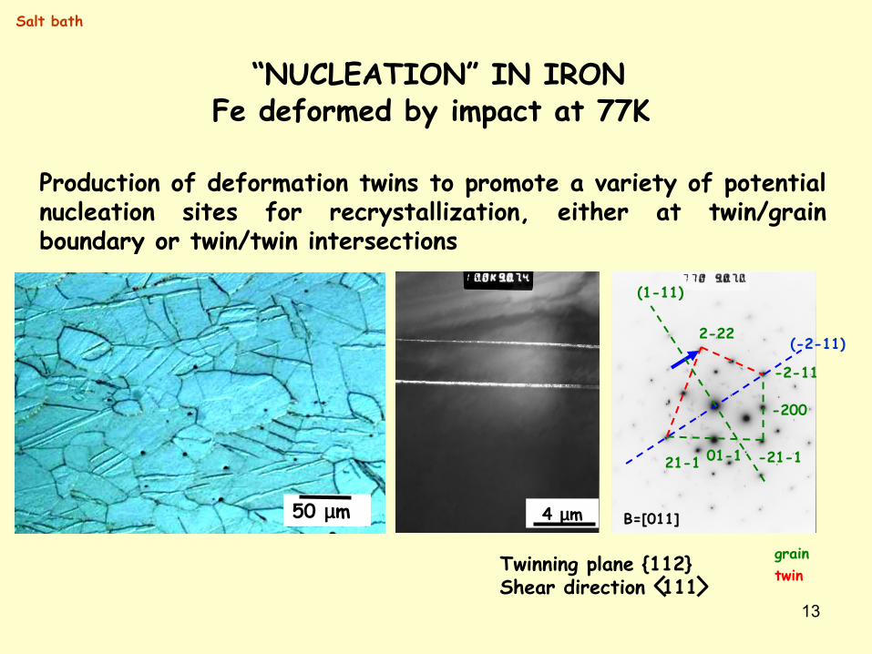
“NUCLEATION” IN IRONFe deformed by impact at 77K
50 µm B=[011]
01-1 -21-1
-200
21-1
-2-11
2-22(-2-11)
(1-11)
graintwinTwinning plane {112}
Shear direction 111
Production of deformation twins to promote a variety of potential nucleation sites for recrystallization, either at twin/grain boundary or twin/twin intersections
4 µm
Salt bath
14
ZA=[011]
ZA=[113] ZA=[113]
ZA=[113]200
0-11
22-2 21-1
ZA=[133]
-110
0-31
12-1 -301
21-1
-110
0-31
12-1-301
21-1
-110
0-31
12-1 -301
21-1
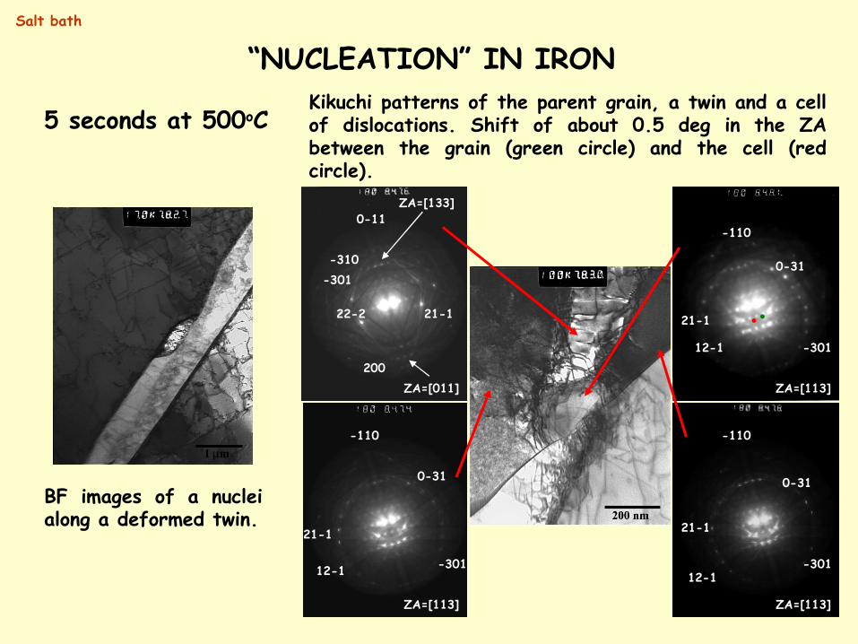
Kikuchi patterns of the parent grain, a twin and a cell of dislocations. Shift of about 0.5 deg in the ZA between the grain (green circle) and the cell (red circle).
-301-310
5 seconds at 500oC
BF images of a nuclei along a deformed twin.
Salt bath
“NUCLEATION” IN IRON
15
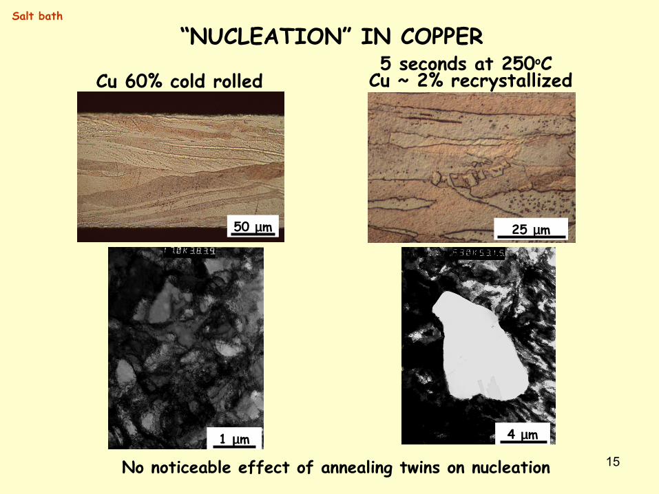
“NUCLEATION” IN COPPER
50 µm
1 µm 4 µm
25 µm
Cu 60% cold rolled Cu ~ 2% recrystallized5 seconds at 250oC
No noticeable effect of annealing twins on nucleation
Salt bath
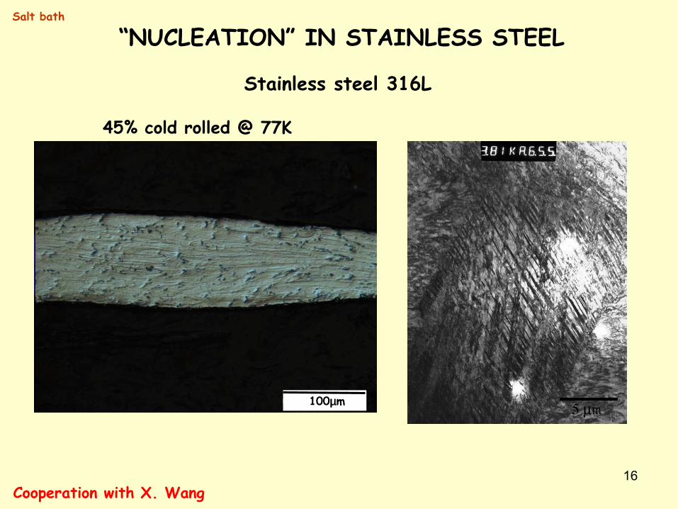
16
45% cold rolled @ 77K
100µm
Stainless steel 316L
Cooperation with X. Wang
Salt bath
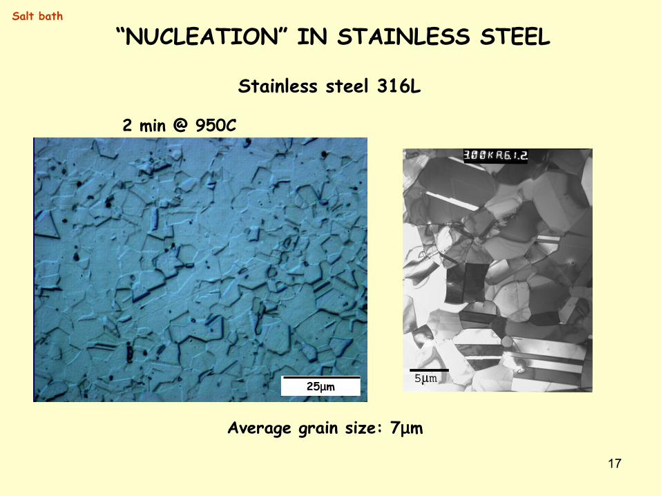
“NUCLEATION” IN STAINLESS STEEL
17
2 min @ 950C
25µm
Stainless steel 316L
Average grain size: 7µm
Salt bath
“NUCLEATION” IN STAINLESS STEEL
18
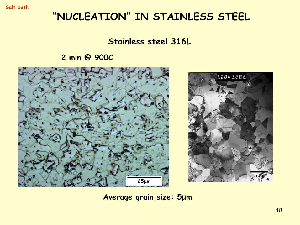
25µm
2 min @ 900C
Stainless steel 316L
Average grain size: 5µm
Salt bath
“NUCLEATION” IN STAINLESS STEEL
19
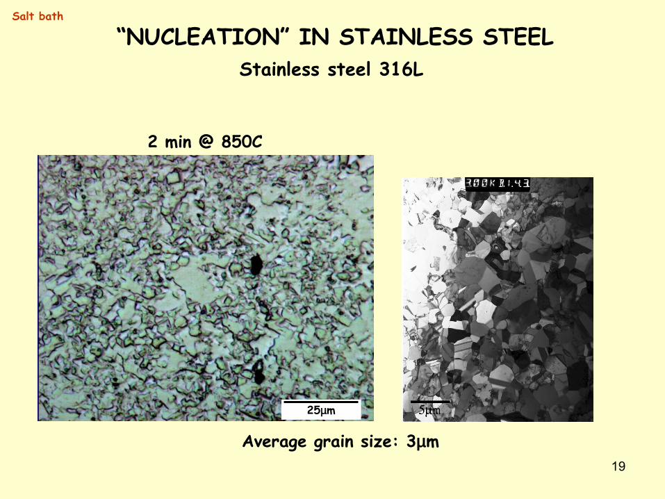
Stainless steel 316L
25µm
2 min @ 850C
Average grain size: 3µm
Salt bath
“NUCLEATION” IN STAINLESS STEEL
20
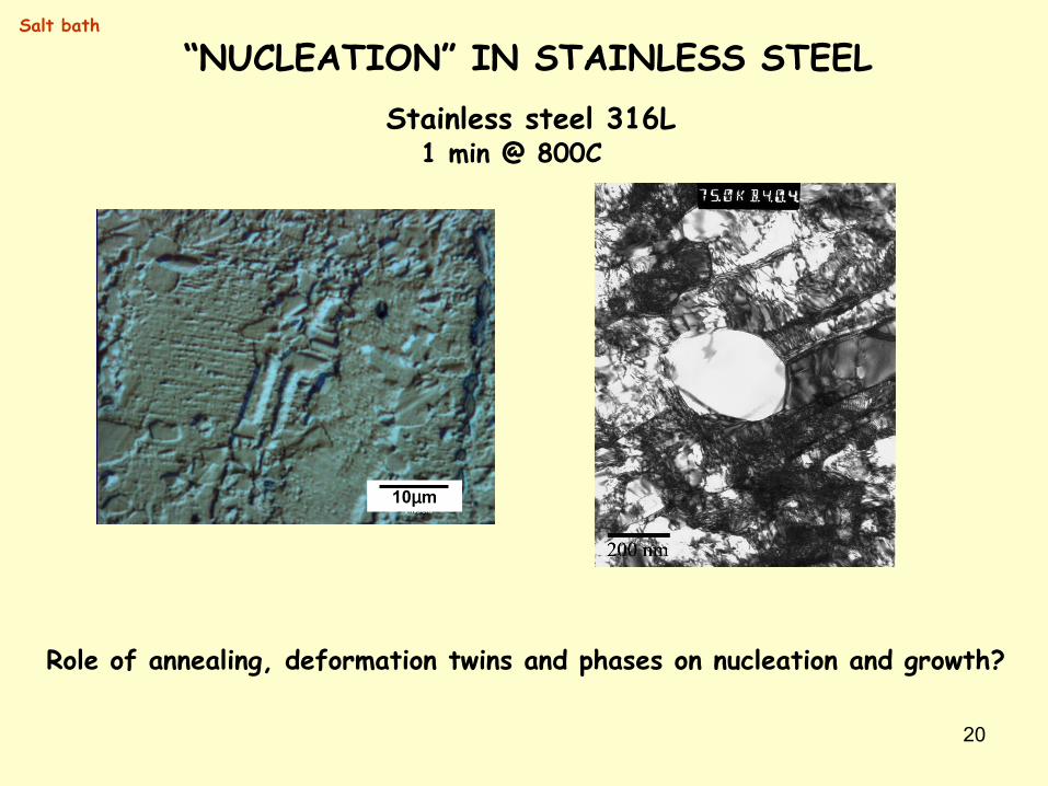
1 min @ 800C
10µm
Role of annealing, deformation twins and phases on nucleation and growth?
Stainless steel 316L
Salt bath
“NUCLEATION” IN STAINLESS STEEL
21
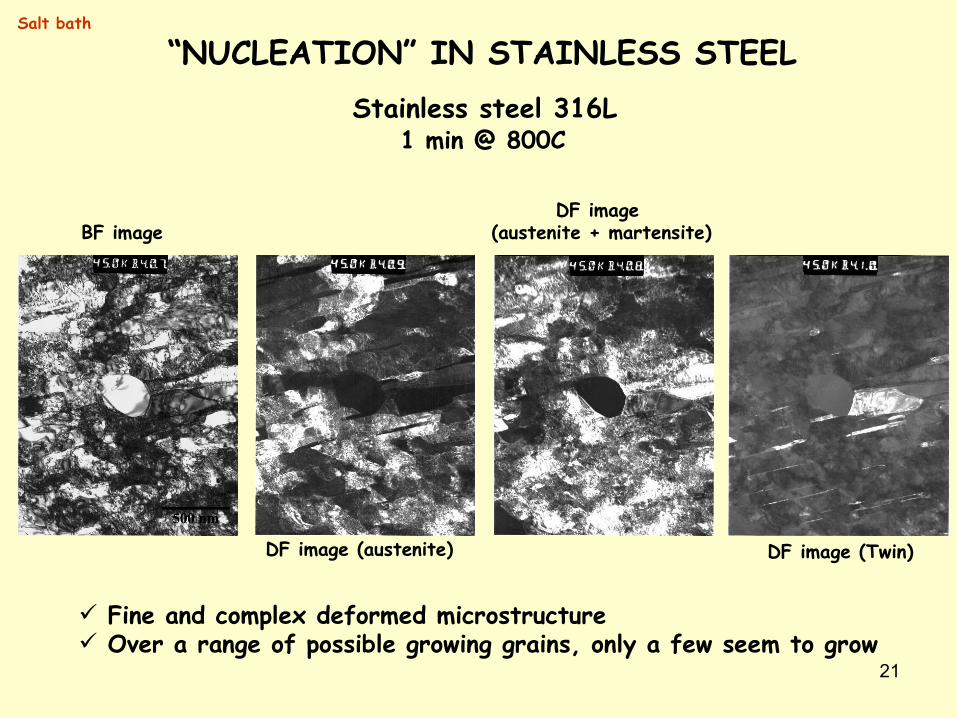
DF image (austenite)
DF image (austenite + martensite)
DF image (Twin)
BF image
Salt bath
1 min @ 800CStainless steel 316L
Fine and complex deformed microstructure Over a range of possible growing grains, only a few seem to grow
“NUCLEATION” IN STAINLESS STEEL
22
Salt bath
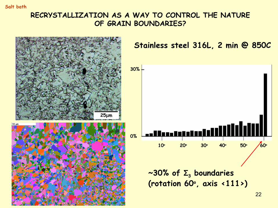
Stainless steel 316L, 2 min @ 850C
25µm
RECRYSTALLIZATION AS A WAY TO CONTROL THE NATURE OF GRAIN BOUNDARIES?
10o 20o 30o 40o 50o 60o
0%
30%
~30% of Σ3 boundaries (rotation 60o, axis <111>)
23
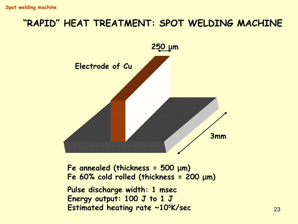
“RAPID” HEAT TREATMENT: SPOT WELDING MACHINE
3mm
250 µm
Fe annealed (thickness = 500 µm)Fe 60% cold rolled (thickness = 200 µm)
Electrode of Cu
Pulse discharge width: 1 msecEnergy output: 100 J to 1 JEstimated heating rate ~105K/sec
Spot welding machine
24
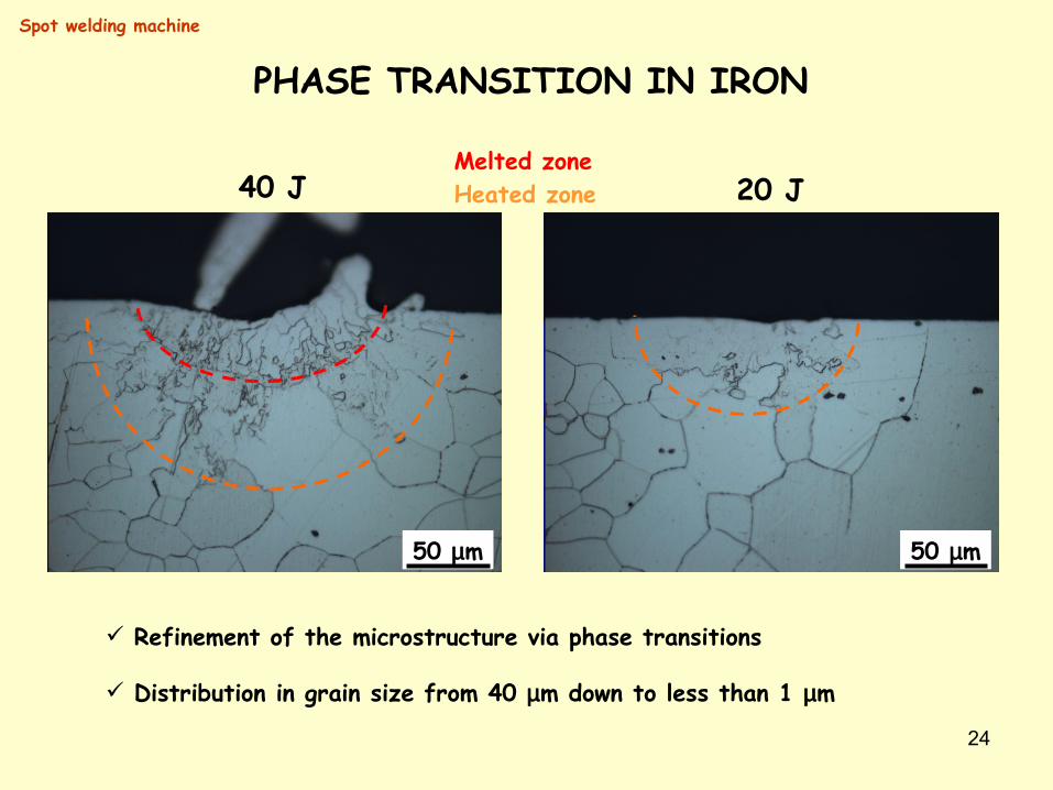
PHASE TRANSITION IN IRON
50 µm 50 µm
40 J 20 JMelted zoneHeated zone
Refinement of the microstructure via phase transitions
Distribution in grain size from 40 µm down to less than 1 µm
Spot welding machine
25
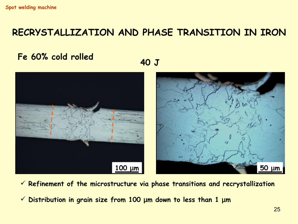
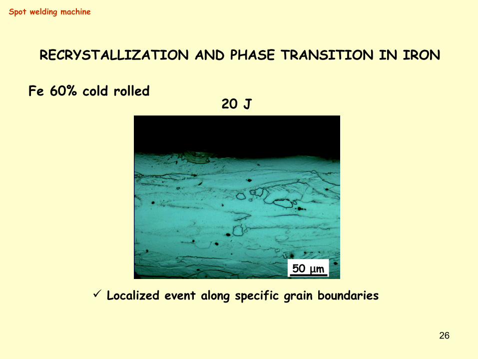
RECRYSTALLIZATION AND PHASE TRANSITION IN IRON
40 J
50 µm100 µm
Refinement of the microstructure via phase transitions and recrystallization
Distribution in grain size from 100 µm down to less than 1 µm
Spot welding machine
Fe 60% cold rolled
26
20 J
50 µm
Localized event along specific grain boundaries
Spot welding machine
RECRYSTALLIZATION AND PHASE TRANSITION IN IRON
Fe 60% cold rolled
27
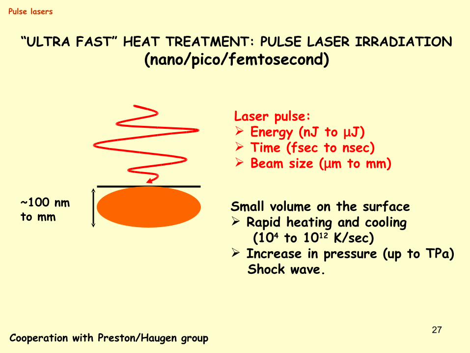
Laser pulse: Energy (nJ to µJ) Time (fsec to nsec) Beam size (µm to mm)
Small volume on the surface Rapid heating and cooling (104 to 1012 K/sec) Increase in pressure (up to TPa) Shock wave.
“ULTRA FAST” HEAT TREATMENT: PULSE LASER IRRADIATION(nano/pico/femtosecond)
Cooperation with Preston/Haugen group
~100 nmto mm
Pulse lasers
28
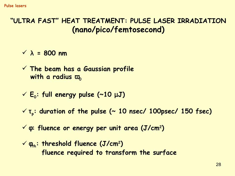
λ = 800 nm
The beam has a Gaussian profile with a radius ω0
E0: full energy pulse (~10 µJ)
τp: duration of the pulse (~ 10 nsec/ 100psec/ 150 fsec)
φ: fluence or energy per unit area (J/cm2)
φth: threshold fluence (J/cm2) fluence required to transform the surface
Pulse lasers
“ULTRA FAST” HEAT TREATMENT: PULSE LASER IRRADIATION(nano/pico/femtosecond)
29
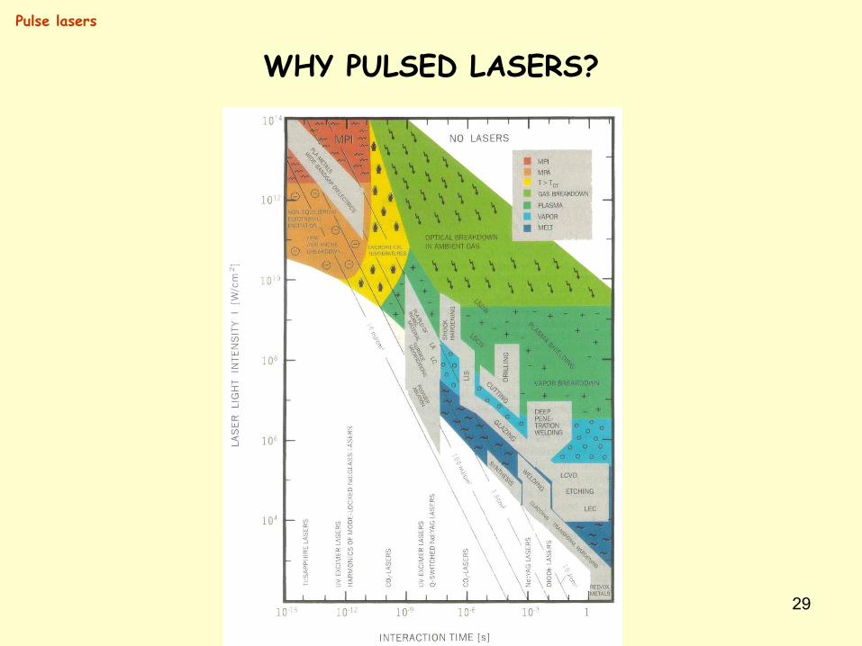
WHY PULSED LASERS?
Pulse lasers
30
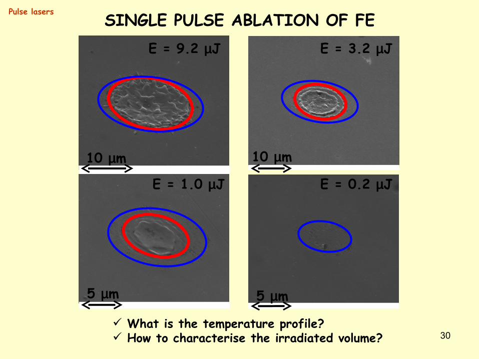
SINGLE PULSE ABLATION OF FEE = 9.2 µJ
10 µm
5 µm
E = 1.0 µJ
10 µm
E = 3.2 µJ
5 µm
E = 0.2 µJ
What is the temperature profile? How to characterise the irradiated volume?
Pulse lasers
31
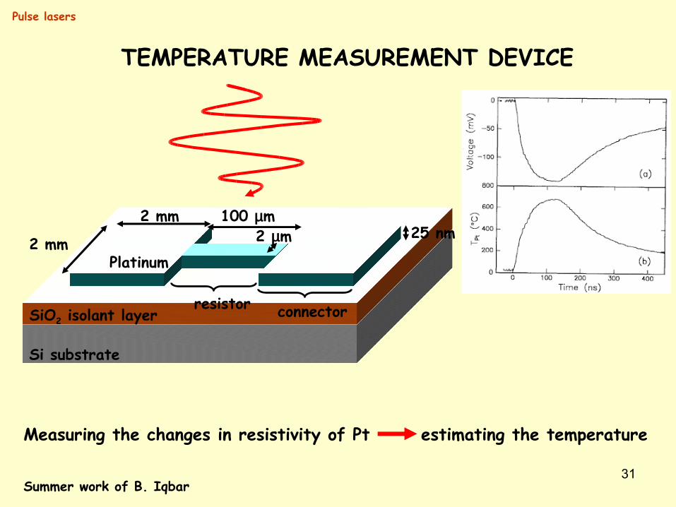
Si substrate
SiO2 isolant layer
Platinum2 mm
2 mm 100 µm25 nm2 µm
resistor connector
TEMPERATURE MEASUREMENT DEVICE
Summer work of B. Iqbar
Measuring the changes in resistivity of Pt estimating the temperature
Pulse lasers

32
Fe annealed, 1 grainCorrected harmonic contact stiffness: 1.106 N/m
0
10
20
30
200 400 600 800 1000 1200
Load On Sample (mN)
Displacement Into Surface (nm)
12345[6]
U
HD
I
E
M HN
L
0
100
200
300
400
200 400 600 800 1000 1200
Reduced Modulus (GPa)
Displacement Into Surface (nm)
12345[6]
IM HN
0
2
4
6
8
10
12
14
16
0 200 400 600 800 1000
Hardness (GPa)
Displacement Into Surface (nm)
12345[6]
IM
HN
INSTRUMENTED INDENTATIONPulse lasers
0
10
20
30
40
200 400 600 800 1000 1200
Load On Sample (mN)
Displacement Into Surface (nm)
[2]34
U
HDI
EM HN
L
Fe annealed, 3 different grains
0
100
200
300
400
200 400 600 800 1000 1200
Reduced Modulus (GPa)
Displacement Into Surface (nm)
[2]34
IMHN
0
2
4
6
8
10
12
14
16
200 400 600 800 1000 1200
Hardness (GPa)
Displacement Into Surface (nm)
[2]34
IM HN
33
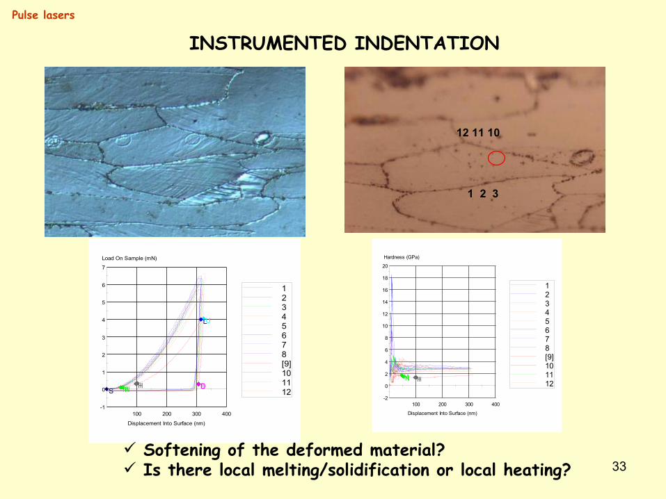
1 2 3
12 11 10
-1
0
1
2
3
4
5
6
7
100 200 300 400
Load On Sample (mN)
Displacement Into Surface (nm)
12345678[9]101112S
U
HDI EM HN
L
-2
0
2
4
6
8
10
12
14
16
18
20
100 200 300 400
Hardness (GPa)
Displacement Into Surface (nm)
12345678[9]101112IM HN
INSTRUMENTED INDENTATIONPulse lasers
Softening of the deformed material? Is there local melting/solidification or local heating?
34
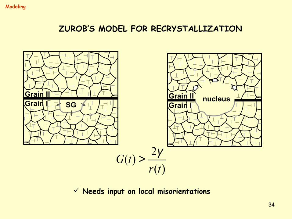
SGGrain IGrain II nucleus
Grain IGrain II
)(2)(tr
tG γ>
Modeling
ZUROB’S MODEL FOR RECRYSTALLIZATION
Needs input on local misorientations
35
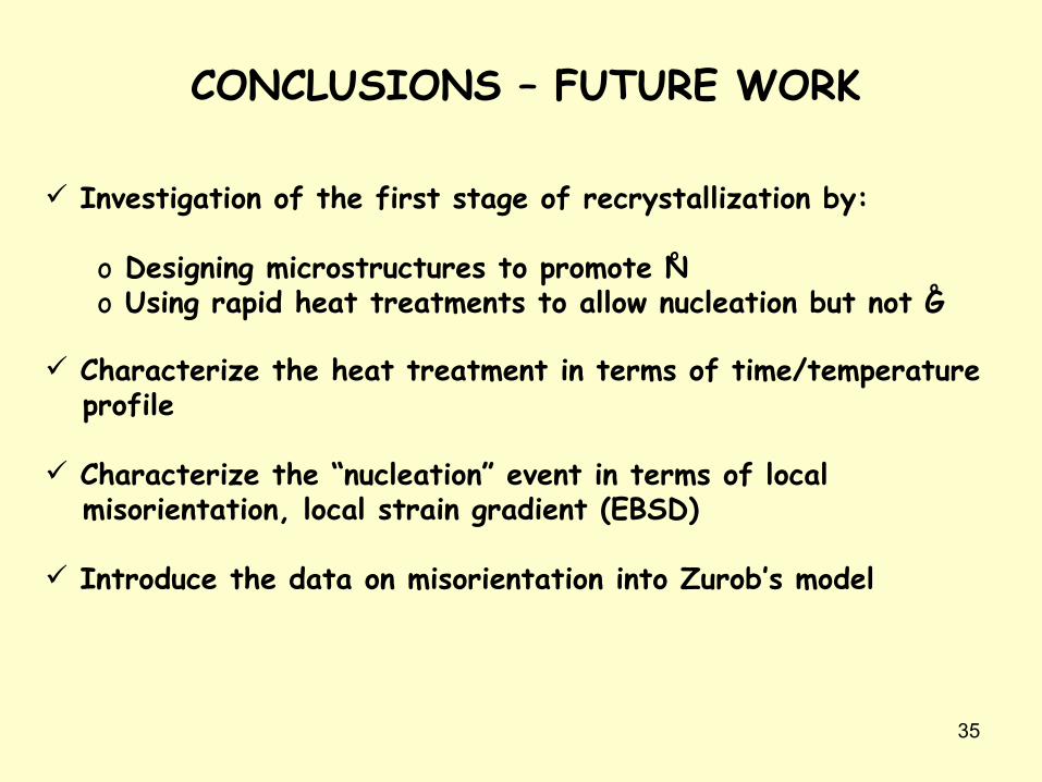
CONCLUSIONS – FUTURE WORK
Investigation of the first stage of recrystallization by:
o Designing microstructures to promote No Using rapid heat treatments to allow nucleation but not G
o
o
Characterize the heat treatment in terms of time/temperature profile
Characterize the “nucleation” event in terms of local misorientation, local strain gradient (EBSD)
Introduce the data on misorientation into Zurob’s model
Related Documents