User’s Guide 500 mA Current Source Module CSM-39050 70012902 August 2011 ILX Lightwave Corporation · 31950 Frontage Road · Bozeman, MT, U.S.A. 59715 · U.S. & Canada: 1-800-459-9459 · International Inquiries: 406-556-2481 · Fax 406-586-9405 ilx.custhelp.com · www.ilxlightwave.com

Welcome message from author
This document is posted to help you gain knowledge. Please leave a comment to let me know what you think about it! Share it to your friends and learn new things together.
Transcript

User’s Guide 500 mA Current Source Module
CSM-39050
70012902 August 2011
ILX Lightwave Corporation · 31950 Frontage Road · Bozeman, MT, U.S.A. 59715 · U.S. & Canada: 1-800-459-9459 · International Inquiries: 406-556-2481 · Fax 406-586-9405
ilx.custhelp.com · www.ilxlightwave.com


39050-1
CSM-39050
500 mA Current Source Module
Instruction Manual
1.0 Introduction
The CSM-39050 500 mA Current Source is a precision current source module for use in the LDC-3900 Modular Laser Diode Controller. It may be installed in any of the four bays at the rear of the LDC-3900 (and may readily be interchanged with any other LDC-3900 module). Features of the CSM-39050 include: Service-free modularity (calibration information is stored on the CSM-39050) Closed-case calibration High-stability, low noise design Flexible setup with LDC-3900 Save/Recall front panel functions Photodiode feedback control mode Modulation input
39050-2
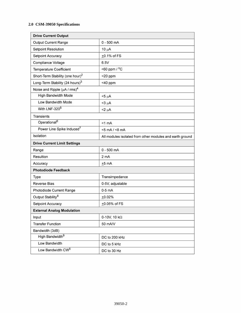
2.0 CSM-39050 Specifications

39050-3
39050-4
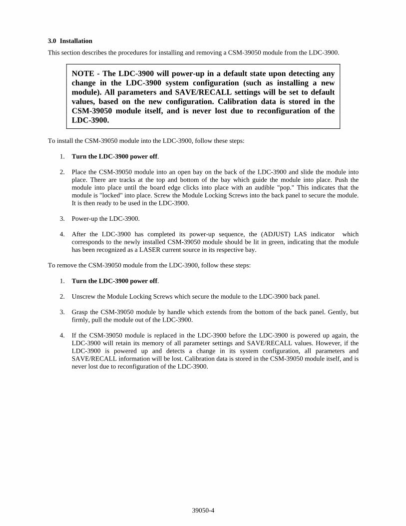
3.0 Installation
This section describes the procedures for installing and removing a CSM-39050 module from the LDC-3900.
NOTE - The LDC-3900 will power-up in a default state upon detecting any change in the LDC-3900 system configuration (such as installing a new module). All parameters and SAVE/RECALL settings will be set to default values, based on the new configuration. Calibration data is stored in the CSM-39050 module itself, and is never lost due to reconfiguration of the LDC-3900.
To install the CSM-39050 module into the LDC-3900, follow these steps: 1. Turn the LDC-3900 power off.
2. Place the CSM-39050 module into an open bay on the back of the LDC-3900 and slide the module into place. There are tracks at the top and bottom of the bay which guide the module into place. Push the module into place until the board edge clicks into place with an audible "pop." This indicates that the module is "locked" into place. Screw the Module Locking Screws into the back panel to secure the module. It is then ready to be used in the LDC-3900.
3. Power-up the LDC-3900. 4. After the LDC-3900 has completed its power-up sequence, the (ADJUST) LAS indicator which
corresponds to the newly installed CSM-39050 module should be lit in green, indicating that the module has been recognized as a LASER current source in its respective bay.
To remove the CSM-39050 module from the LDC-3900, follow these steps:
1. Turn the LDC-3900 power off. 2. Unscrew the Module Locking Screws which secure the module to the LDC-3900 back panel. 3. Grasp the CSM-39050 module by handle which extends from the bottom of the back panel. Gently, but
firmly, pull the module out of the LDC-3900. 4. If the CSM-39050 module is replaced in the LDC-3900 before the LDC-3900 is powered up again, the
LDC-3900 will retain its memory of all parameter settings and SAVE/RECALL values. However, if the LDC-3900 is powered up and detects a change in its system configuration, all parameters and SAVE/RECALL information will be lost. Calibration data is stored in the CSM-39050 module itself, and is never lost due to reconfiguration of the LDC-3900.
39050-5
4.0 Operation
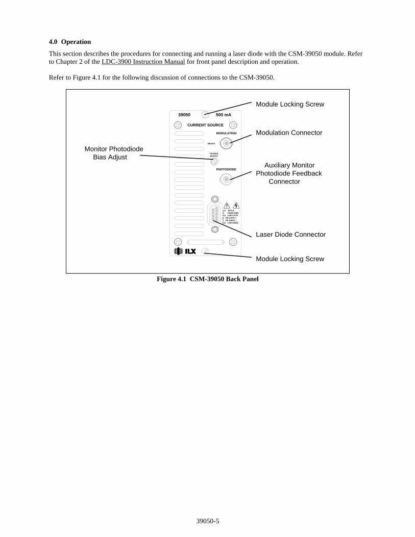
This section describes the procedures for connecting and running a laser diode with the CSM-39050 module. Refer to Chapter 2 of the LDC-3900 Instruction Manual for front panel description and operation. Refer to Figure 4.1 for the following discussion of connections to the CSM-39050.
LSR CATH
LSR ANOD
PD CATH +PD ANOD -
CHAS GNDINTLK
8,9
4,5
76
1,23
50mA/V
ADJUST
PHOTODIODE
MODULATION
PD BIAS
CURRENT SOURCE
39050 500 mA
Laser Diode Connector
Photodiode Feedback
Monitor PhotodiodeBias Adjust
Modulation Connector
Connector
Auxiliary Monitor
Module Locking Screw
Module Locking Screw
Figure 4.1 CSM-39050 Back Panel

39050-6
4.1 The LASER Connector
On the back panel of the CSM-39050 you will find a 9-pin D-connector for the LD connections. The pinout diagram for this connector is shown in Figure 4.2.
1
2
3
4
5
7
8
9
61, 2 Interlock3 Chassis Ground4, 5 Laser Cathode6 PD Cathode (+)7 PD Anode (-)8, 9 Laser Anode
Figure 4.2 Back Panel LD Connector
4.2 Connecting to Your Laser
When connecting laser diodes and other sensitive devices to the CSM-39050, we recommend that the LDC-3900 be powered up and the LASER output be off (LASER MODE ON LED unlit). In this condition, a low impedance shunt is active across the output terminals. When disconnecting devices, it is only necessary to turn the LASER Output off.
4.3 Laser Diode Connections and Shielding
IMPORTANT
Before connecting the laser diode to the LDC-3900 Modular Laser Diode Controller, be sure that the front panel (LASER MODE) ON switch is in the OFF position (ON LED unlit). Before turning on the LASER output, be sure that the current limit has been correctly set.
Figures 4.3 A - D show the possible configurations of connecting laser diodes and photodiodes with the LDC-3900 Modular Laser Diode Controller.

39050-7
+
-+
Bias
3900 Modular Laser Diode ControllerOUTPUT
7
6
8, 9
4, 5
3P. D. L. D.
Earth Ground
Figure 4.3A Common Laser Cathode - Photodiode Cathode
+
-+
Bias
3900 Modular Laser Diode ControllerOUTPUT
7
6
8, 9
4, 5
3P. D. L. D.
Earth Ground
Figure 4.3B Common Laser Cathode - Photodiode Anode

39050-8
+
-+
Bias
3900 Modular Laser Diode ControllerOUTPUT
7
6
8, 9
4, 5
3P. D. L. D.
Earth Ground
Figure 4.3C Common Laser Anode - Photodiode Cathode
+
-+
Bias
3900 Modular Laser Diode ControllerOUTPUT
7
6
8, 9
4, 5
3P. D. L. D.
Earth Ground
Figure 4.3D Common Laser Anode - Photodiode Anode
39050-9
IMPORTANT
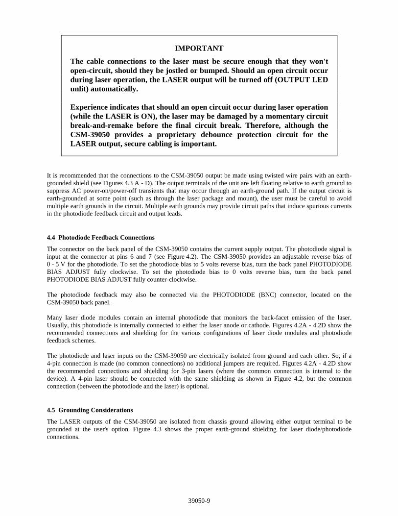
The cable connections to the laser must be secure enough that they won't open-circuit, should they be jostled or bumped. Should an open circuit occur during laser operation, the LASER output will be turned off (OUTPUT LED unlit) automatically.
Experience indicates that should an open circuit occur during laser operation (while the LASER is ON), the laser may be damaged by a momentary circuit break-and-remake before the final circuit break. Therefore, although the CSM-39050 provides a proprietary debounce protection circuit for the LASER output, secure cabling is important.
It is recommended that the connections to the CSM-39050 output be made using twisted wire pairs with an earth-grounded shield (see Figures 4.3 A - D). The output terminals of the unit are left floating relative to earth ground to suppress AC power-on/power-off transients that may occur through an earth-ground path. If the output circuit is earth-grounded at some point (such as through the laser package and mount), the user must be careful to avoid multiple earth grounds in the circuit. Multiple earth grounds may provide circuit paths that induce spurious currents in the photodiode feedback circuit and output leads. 4.4 Photodiode Feedback Connections
The connector on the back panel of the CSM-39050 contains the current supply output. The photodiode signal is input at the connector at pins 6 and 7 (see Figure 4.2). The CSM-39050 provides an adjustable reverse bias of 0 - 5 V for the photodiode. To set the photodiode bias to 5 volts reverse bias, turn the back panel PHOTODIODE BIAS ADJUST fully clockwise. To set the photodiode bias to 0 volts reverse bias, turn the back panel PHOTODIODE BIAS ADJUST fully counter-clockwise. The photodiode feedback may also be connected via the PHOTODIODE (BNC) connector, located on the CSM-39050 back panel. Many laser diode modules contain an internal photodiode that monitors the back-facet emission of the laser. Usually, this photodiode is internally connected to either the laser anode or cathode. Figures 4.2A - 4.2D show the recommended connections and shielding for the various configurations of laser diode modules and photodiode feedback schemes. The photodiode and laser inputs on the CSM-39050 are electrically isolated from ground and each other. So, if a 4-pin connection is made (no common connections) no additional jumpers are required. Figures 4.2A - 4.2D show the recommended connections and shielding for 3-pin lasers (where the common connection is internal to the device). A 4-pin laser should be connected with the same shielding as shown in Figure 4.2, but the common connection (between the photodiode and the laser) is optional. 4.5 Grounding Considerations
The LASER outputs of the CSM-39050 are isolated from chassis ground allowing either output terminal to be grounded at the user's option. Figure 4.3 shows the proper earth-ground shielding for laser diode/photodiode connections.

39050-10
4.6 Modulation Connections
The MODULATION connector allows a 50 mV/A modulation signal to be applied to the laser. The modulation port input impedance is 10 k. 5.0 Calibration
The CSM-39050 should be calibrated every 12 months or whenever performance verification indicates that calibration is necessary. All calibrations can be done with the case closed. The instrument is calibrated by changing the internally stored digital calibration constants. 5.1 Recommended Equipment
Recommended test equipment for calibrating the CSM-39050 is listed in Table 5.1. Equipment other than that shown in the table may be used if the specifications meet or exceed those listed. If your LDC-3900 is equipped with the model 1231 GPIB/IEEE-488.2 interface you may refer to sections 5.4.2, 5.4.4 and 5.4.6 for calibration procedures using the GPIB, if desired.
RECOMMENDED TEST EQUIPMENT
Description Mfg./Model Specification DMM HP 3457A 0.1 A or 0.1 mV resolution Resistor 15 , 5 W, low TCR, for voltage cal. IPD Calibration Resistors Metal Film 49 , and 100 , 1%, 1/4 W High-power 5 , 5 W, low TCR Optical Isolator TIL117 or equivalent, 6-pin Connector D-sub 9-pin male
Table 5.1 Recommended Test Equipment
5.2 Environmental Conditions
Calibrate this instrument under laboratory conditions. We recommend calibration at 23C ± 1.0C. When necessary, however, the CSM-39050 may be calibrated at its intended use temperature if this is within the specified operating temperature range of 0 to 50C. 5.3 Warm-Up
The LDC-CSM-39050 should be allowed to warm up for at least 1 hour before calibration.

39050-11
5.4 LASER Controller Calibration Procedures
There are three calibration procedures that need to be made for the CSM-39050. They are calibration of the constant current source (for both bandwidths), calibration of the laser voltage measurement, and calibration of the constant light power (IPD) feedback circuits. The CSM-39050 implements a two-point calibration for the Laser current source. Two currents are applied to a load, and the resulting measured currents are fed back (by the user) to the CSM-39050. The CSM-39050 calibration program uses the two data points to calculate calibration constants that it will thereafter use to set current. If you have the optional Model 1231 IEEE-488.2/GPIB interface you may follow the procedure in sections 5.4.2, 5.4.4, and 5.4.6 to calibrate the CSM-39050 remotely. 5.4.1 Local Operation Current Source Calibration
The following procedure is for local (front panel) operation. See Section 5.4.2 for remote calibration of the current source.
a. Select the CSM-39050 to be calibrated by pressing the appropriate (ADJUST) switch. Set the LASER current limit (LIM I) to full scale, bandwidth as desired, and current set point to 400 mA (80% of full scale). Connect a calibrated DMM to measure the current across the output (pins 5 and 8).
b. Turn the (LASER ENABLE) ON switch and press the appropriate OUTPUT switch to turn the LASER
output on. If the LASER output is not on, the LASER I calibration mode cannot be entered. If the LASER output is on, but the LASER channel is not selected (see Step a), calibration will be performed improperly.
c. Enter the LASER I calibration mode by pushing the (GPIB) LOCAL and (LASER DISPLAY) I switches at
the same time. The LASER display will indicate output current in mA. The LDC-3900 will beep when it is ready to accept a new calibration value.
d. Press and hold in the (PARAMETER) SET switch and turn the ADJUST knob until the LASER display
indicates the same current as measured via the DMM. e. Release the (PARAMETER) SET switch to accept the first calibration value. After the (LASER
DISPLAY) SET switch is released, the LDC-3900 will beep. It will then apply the second calibration current, approximately one-fourth of the original current.
f. The LDC-3900 will beep when it is ready to accept the second calibration value. When it does, press and
hold in the (PARAMETER) SET switch and turn the ADJUST knob until the LASER display indicates the same current as measured via the DMM.
g. Release the (PARAMETER) SET switch to accept the second calibration value. After the (PARAMETER)
SET switch is released, the LDC-3900 will calculate the calibration constants, store them to nonvolatile memory on the CSM-39050, beep, and return to its former (before calibration) state.
h. Repeat this procedure with the other bandwidth, if desired.

39050-12
5.4.2 Remote Operation Current Source Calibration
The following procedure is for remote (GPIB) operation. See Section 5.4.1 for local calibration of the current source.
a. Select the CSM-39050 to be calibrated by sending the "LAS:CHAN x" command, where x is the channel of the CSM-39050. Set the LASER limit to full scale via the "LAS:LIM:I 500" command, output bandwidth as desired via the "LAS:MODE" command, and current set point to 80% of full scale via the "LAS:LDI 400" command. Connect a calibrated DMM to measure the current across the laser output (pins 5 and 8).
b. Turn the (LASER ENABLE) ON switch. Enter the "LAS:OUT ON" command to turn the LASER output
on. If the LASER output is not on, the LASER I calibration mode cannot be entered. c. Enter the LASER I calibration mode by issuing the "LAS:CAL:LDI" command. The LDC-3900 will beep
when it is ready to accept the first calibration point. d. Input the first actual (measured) LASER output current (as an <nrf value>) via the "LAS:LDI <nrf value>"
command. If this value is to be measured and entered remotely via a GPIB controlled DMM, for example, the
measured value of the current should not be entered until the LDC-3900 is ready to receive it. The LDC-3900 will be ready to receive the current value when, after a "LAS:CAL:LDI?" query is sent, the
response from the LDC-3900 is "1". e. Once the actual I value is entered via the "LAS:LDI" command, the LDC-3900 will beep and will apply a
new current equal to approximately one-fourth (1/4) the previous set current. The LDC-3900 will be ready to receive the second current value when, after a "LAS:CAL:LDI?" query is sent, the response from the LDC-3900 is "1".
f. Input the second actual (measured) LASER output current (as an <nrf value>) as in Step d. g. Once the second actual I value is entered via the "LAS:LDI" command, the LDC-3900 will beep and the
new calibration constants will be calculated and stored into non-volatile memory on the CSM-39050. The "OPC?" query may be used (after the "LAS:LDI" value is sent) to determine when the calibration is completed.
The operation complete flag (bit 0 of the Standard Event Status Register) may be used to trigger a service
request. This type of interrupt is enabled by setting bit 0 of the Service Request Enable register (via the *ESE command) and bit 5 of the Service Request Enable register (via the *SRE command). Service request (SRQ) handling depends on your GPIB hardware. Refer to your GPIB user's manual for details.
h. Repeat this procedure with the other range, if desired.

39050-13
5.4.3 Local Operation IPD Current Calibration
The following procedure is for calibrating the LASER IPD constant current source. This procedure calibrates the feedback circuits for constant IPD and constant PPD modes. When these values are reached and are stable, the user enters the actual value of the current, as measured by an external DMM. The CSM-39050 then automatically calibrates the LASER feedback circuits. This procedure is for local (front panel) operation. See Section 5.4.4 for remote calibration of the IPD current.
a. Select the CSM-39050 to be calibrated by pressing the appropriate (ADJUST) switch. With the LASER output off, connect a calibrated ammeter to the PD Anode output of the CSM-39050, and connect the circuit of Figure 5.1 to the LASER and PD outputs.
If a calibrated ammeter (with 0.1 A resolution) is not available, place a calibrated DMM (with 0.1 mV
resolution) to measure the voltage across the resistor, R1, as shown in Figure 6.1. Calculate the current in the following steps by using Ohm's Law:
I = E / R
-where E is the accurately measured voltage across the resistor, and R is the accurately measured load
resistance. (A 4-point probe resistance measurement is recommended.)
U1 TIL117
1
2
34
5
6A
VR3R2
1009-Pin D-Sub
LD Cathode (5)
LD Anode (9)
PD Cathode + (6)
PD Anode - (7)
Voltmeter
Ammeter R149
Ipd Current
R41 M
CALIBRATION CIRCUIT
9 V Batt
Interlock - (1)
Interlock - (2)
Figure 5.1 IPD Calibration Circuit
b. Set the LASER current limit (LIM I) to 500 mA. Set the IPD set point to 4000 A, and set the CAL PD
parameter to zero. This puts the CSM-39050 into a constant IPD mode. c. Turn the (LASER ENABLE) ON switch and press the appropriate OUTPUT switch to turn the LASER
output on. If the LASER output is not on, the LASER IPD calibration mode cannot be entered. d. Press the (GPIB) LOCAL and (LASER DISPLAY) IPD/PPD switches at the same time to place the
CSM-39050 in its LASER IPD Calibration mode. After a few seconds the LDC-3900 will beep and the LASER display will show the IPD set point value. e. After the value on the LASER display is stable (has not changed by more than one digit for several
seconds) the CSM-39050 is ready for the actual IPD value to be entered.
39050-14
Press and hold in the (PARAMETER) SET switch and turn the ADJUST knob until the LASER display
shows the correct value, as shown on the calibrated ammeter (or the calculated IPD value from Step a). f. Release the (PARAMETER) SET switch to store the first calibration value into non-volatile memory. It
will then expect the second calibration current current, approximately one-fourth of the original current. g. The LDC-3900 will beep when it is ready to accept the second calibration value. When it does, press and
hold in the (PARAMETER) SET switch and turn the ADJUST knob until the LASER display indicates the same current (as measured directly, or as calculated in Step a, from the measured voltage).
h. Release the (PARAMETER) SET switch to accept the second calibration point. After the (PARAMETER)
SET switch is released, the LDC-3900 will calculate the calibration constants, store them to nonvolatile memory on the CSM-39050, beep, and return to its former (before calibration) state.
5.4.4 Remote Operation IPD Current Calibration
The following procedure is for calibrating the LASER IPD constant current source over GPIB. This procedure calibrates the feedback circuits for constant IPD and constant PPD modes. When these values are reached and are stable, the user enters the actual value of the current, as measured by an external DMM. The CSM-39050 then automatically calibrates the LASER feedback circuits. This procedure is for remote (GPIB) operation. See Section 5.4.3 for local calibration of the IPD current.
a. With the LASER output off, connect a calibrated ammeter to the PD Anode output of the CSM-39050, and connect the circuit of Figure 5.1 to the LASER and PD outputs.
If a calibrated ammeter (with 0.1 A resolution) is not available, place a calibrated DMM (with 0.1 mV
resolution) to measure the voltage across the resistor, R1, as shown in Figure 5.1. Calculate the current in the following steps by using Ohm's Law:
I = E / R
-where E is the accurately measured voltage across the resistor, and R is the accurately measured load
resistance. (A 4-point probe resistance measurement is recommended.) b. Select the CSM-39050 to be calibrated by sending the "LAS:CHAN x" command, where x is the channel
of the CSM-39050. Set the LASER current limit via the "LAS:LIM:I 500" command. Set the IPD set point to 4000 A via the "LAS:MDI 4000" command. Set the CAL PD parameter to zero via the "LAS:CALMD 0" command. This puts the CSM-39050 into a constant IPD (MDI) mode.
c. Turn the (LASER ENABLE) ON switch. Enter the "LAS:OUT ON" command to turn the LASER output
on. If the LASER output is not on, the LASER IPD calibration mode cannot be entered. d. Enter the "LAS:CAL:MDI" command to place the CSM-39050 in its LASER IPD Calibration mode. e. After a few seconds, the LDC-3900 will be ready for the actual IPD current to be entered via the
"LAS:MDI" command. The measured value of the current should not be entered until the LDC-3900 is ready to receive it. The LDC-3900 will beep when it is ready to accept a new calibration value.
The LDC-3900 will be ready to receive the IPD value when, after a "LAS:CAL:MDI?" query is sent, the
response from the LDC-3900 is "1".

39050-15
f. Once the actual I value is entered via the "LAS:MDI" command, the LDC-3900 will beep and the new
calibration value will be stored into non-volatile memory. It will then set the current to approximately one-fourth of the original current and expect the second calibration value to be entered. The LDC-3900 will be ready to receive the second IPD value when, after a "LAS:CAL:MDI?" query is sent, the response from the LDC-3900 is "1".
g. Input the second actual (measured) IPD current (as an <nrf value>) as in Step e. h. Once the second actual monitor diode current value is entered via the "LAS:MDI" command, the
LDC-3900 will beep and the new calibration constants will be calculated and stored into non-volatile memory in the CSM-3900. The "OPC?" query may be used (after the "LAS:MDI" value is sent) to determine when the calibration is completed.
The operation complete flag (bit 0 of the Standard Event Status Register) may be used to trigger a service
request. This type of interrupt is enabled by setting bit 0 of the Service Request Enable register (via the *ESE command) and bit 5 of the Service Request Enable register (via the *SRE command). Service request (SRQ) handling depends on your GPIB hardware. Refer to your GPIB user's manual for details.
5.4.5 Local Operation Laser Voltage Measurement Calibration
The following procedure is for calibrating the LASER voltage measurement via the front panel. See Section 5.4.5 for remote (GPIB) calibration of the voltage measurement.
a. With the LASER output off, connect a calibrated voltmeter, in parallel with a 15 , 5 Watt, low temperature coefficient resistor, to the LASER output of the CSM-39050 (pins 5 and 8).
b. Select the CSM-39050 to be calibrated by pressing the appropriate (ADJUST) switch. Set the LASER current limit (LIM I) to 500 mA. Set the LASER I set point to 400 mA.
c. Turn the (LASER ENABLE) ON switch and press the appropriate OUTPUT switch to turn the LASER output on. If the LASER output is not on, the LASER voltage calibration mode cannot be entered.
d. Press the (GPIB) LOCAL and (LASER DISPLAY) V switches at the same time to place the CSM-39050
in its LASER Voltage Calibration mode. e. After a few seconds, the LDC-3900 will beep when it is ready to accept a new calibration value. Press and
hold in the (PARAMETER) SET switch and turn the ADJUST knob to enter the LASER voltage measurement value which appears on the DMM. Release the (PARAMETER) SET switch to enter the value.
Once the actual voltage value is entered, the LDC-3900 will beep. It will then set the output to
approximately one-fourth of the original voltage, and then it will expect the second calibration voltage point to be entered
f. Input the second actual (measured) LASER voltage (as an <nrf value>) as in Step e. g. Once the second actual voltage value is entered, the LDC-3900 will beep and the new calibration constants
will be calculated and stored into non-volatile memory on the CSM-39050.

39050-16
5.4.6 Remote Operation Laser Voltage Measurement Calibration
The following procedure is for calibrating the LASER voltage measurement via GPIB. See Section 5.4.5 for local calibration of the voltage measurement.
a. With the LASER output off, connect a calibrated voltmeter, in parallel with a 15 , 5 Watt, low temperature coefficient resistor, to the LASER output of the CSM-39050 (pins 5 and 8).
b. Select the CSM-39050 to be calibrated by sending the appropriate "LAS:CHAN x" command, where x is the channel number of the CSM-39050. Set the LASER current limit via the "LAS:LIM:I 500". Set the I
set point via the "LAS:LDI 400" command.
c. Turn the (LASER ENABLE) ON switch. Enter the "LAS:OUT ON" command to turn the LASER output on. If the LASER output is not on, the LASER voltage calibration mode cannot be entered.
d. Enter the "LAS:CAL:LDV" command to place the CSM-39050 in its LASER Voltage Calibration mode. e. After a few seconds, the LDC-3900 will be ready for the actual laser voltage to be entered via the
"LAS:LDV" command. The measured value of the voltage should not be entered until the LDC-3900 is ready to receive it.
The LDC-3900 will be ready to receive the voltage value when, after a "LAS:CAL:LDV?" query is sent,
the response from the LDC-3900 is "1". f. Once the actual voltage value is entered via the "LAS:LDV" command, the LDC-3900 will beep. It will
then expect the second calibration voltage point, approximately one-fourth of the original voltage. The LDC-3900 will be ready to receive the second voltage value when, after a "LAS:CAL:LDV?" query is sent, the response from the LDC-3900 is "1".
g. Input the second actual (measured) LASER voltage (as an <nrf value>) as in Step e. h. Once the second actual voltage value is entered via the "LAS:LDV" command, the LDC-3900 will beep
and the new calibration constants will be calculated and stored into non-volatile memory on the CSM-39050.
The operation complete flag (bit 0 of the Standard Event Status Register) may be used to trigger a service
request. This type of interrupt is enabled by setting bit 0 of the Service Request Enable register (via the *ESE command) and bit 5 of the Service Request Enable register (via the *SRE command). Service request (SRQ) handling depends on your GPIB hardware. Refer to your GPIB user's manual for details.
Related Documents