Soil and Sediment Sampling Procedures Quality Assurance Systems Requirements 7-1 March 09 7.0 SOIL AND SEDIMENT SAMPLING PROCEDURES 7.1 Purpose The purpose of this chapter is to identify and describe procedures and protocols for soil and sediment sampling. The chapter is intended to guide and help CERP project personnel and authorized contractors who are performing soil or sediment sampling activities related to CERP achieve a level of acceptable quality, standardization, and consistency. These soil and sediment sampling activities will be performed by multiple entities, including universities, public agencies, and private contractors. Data may be used for multiple purposes and will be shared by various groups. Therefore, all data must meet a minimum level of quality and completeness to assure consistency within the program and to allow effective sharing of data. For these reasons, written requirements and guidance are critical so that multiple participants are able to collect the type of data needed to achieve the goals of assessing the effect of CERP projects. This chapter is not intended to be prescriptive, but is intended to assure that acceptable field methods and QA/QC procedures are used when performing environmental investigations. It outlines the minimum DQOs and reporting elements required and provides a list of known methods. This is intended to be a dynamic document that will be reviewed and updated periodically. Additional analytical requirements, QA/QC, and data validation protocols are addressed in other chapters of the QASR document. Users should be familiar with and apply relevant provisions in other chapters of the QASR, as well as other technical documents when preparing project plans, identifying data quality elements, validating the data, or making an assessment and inference about gathered data. Links to relevant QASR chapters and other technical documents are provided throughout this document. 7.2 Scope The goals of this chapter of the QASR are: • To guide project personnel, principal investigators, and consultants in data gathering protocols and QA/QC activities related to soil and sediment sampling procedures; • To promote uniformity and consistency in protocols and achieve comparability in data and information collected across projects and among different groups; • To identify the minimum data quality and reporting requirements that should be met regardless of changes in PIs, project personnel, and methods; • To help ensure conformance with applicable local, state, and federal regulations, and • To help maintain traceability and verifiability of findings. Soil and sediment sampling methods (Appendix 7A) and analyses may include: • In situ surveys and physical measurements (Appendix 7B) • Collection for laboratory analysis

Welcome message from author
This document is posted to help you gain knowledge. Please leave a comment to let me know what you think about it! Share it to your friends and learn new things together.
Transcript

Soil and Sediment Sampling Procedures
Quality Assurance Systems Requirements 7-1 March 09
7.0 SOIL AND SEDIMENT SAMPLING PROCEDURES
7.1 Purpose
The purpose of this chapter is to identify and describe procedures and protocols for soil and sediment sampling. The chapter is intended to guide and help CERP project personnel and authorized contractors who are performing soil or sediment sampling activities related to CERP achieve a level of acceptable quality, standardization, and consistency. These soil and sediment sampling activities will be performed by multiple entities, including universities, public agencies, and private contractors. Data may be used for multiple purposes and will be shared by various groups. Therefore, all data must meet a minimum level of quality and completeness to assure consistency within the program and to allow effective sharing of data. For these reasons, written requirements and guidance are critical so that multiple participants are able to collect the type of data needed to achieve the goals of assessing the effect of CERP projects.
This chapter is not intended to be prescriptive, but is intended to assure that acceptable field methods and QA/QC procedures are used when performing environmental investigations. It outlines the minimum DQOs and reporting elements required and provides a list of known methods. This is intended to be a dynamic document that will be reviewed and updated periodically.
Additional analytical requirements, QA/QC, and data validation protocols are addressed in other chapters of the QASR document. Users should be familiar with and apply relevant provisions in other chapters of the QASR, as well as other technical documents when preparing project plans, identifying data quality elements, validating the data, or making an assessment and inference about gathered data. Links to relevant QASR chapters and other technical documents are provided throughout this document.
7.2 Scope
The goals of this chapter of the QASR are:
• To guide project personnel, principal investigators, and consultants in data gathering protocols and QA/QC activities related to soil and sediment sampling procedures;
• To promote uniformity and consistency in protocols and achieve comparability in data and information collected across projects and among different groups;
• To identify the minimum data quality and reporting requirements that should be met regardless of changes in PIs, project personnel, and methods;
• To help ensure conformance with applicable local, state, and federal regulations, and
• To help maintain traceability and verifiability of findings.
Soil and sediment sampling methods (Appendix 7A) and analyses may include:
• In situ surveys and physical measurements (Appendix 7B)
• Collection for laboratory analysis
Soil and Sediment Sampling Procedures
Quality Assurance Systems Requirements 7-2 March 09
• Ecological Laboratory analyses (Appendix 7C); or
• Mesocosms, laboratory assays, and controlled studies.
These studies will provide data and information for a variety of CERP projects in the following areas:
• Monitoring changes in sediment or soil elevation
• Soil accretion and sediment deposition
• Monitoring rates of surface accretion
• Sedimentation rates and vertical accumulation including sediment type
• Biogeochemistry
• Redox
• Oxygen demand
• Oxygen content
• Respiration
• Organic matter decomposition
• Microbial biomass
• pH
• Organic matter
• Salinity
• Moisture content
• Bulk density
• Marl prairie and slough gradients.
Specific methods known to be accepted for use in South Florida ecosystems at the time of preparation of this manual are included in this chapter.
7.3 Requirements and Regulations
7.3.1 Federal Requirements and Regulations
• CFR, Title 40
• USACE EM 1110-1-1906 Laboratory Soil Testing
• USACE EM 1110-2-5027 Confined Disposal of Dredged Material
• US EPA SOP for Soil Sampling (SOP #2012 Rev. 2/18/00)
• CGM 42: Toxic Substances Screening Process - Mercury and Pesticides (9/17/2005)

Soil and Sediment Sampling Procedures
Quality Assurance Systems Requirements 7-3 March 09
7.3.2 State Requirements and Regulations
• FDEP SOP-001/01 FC1000 Cleaning and Decontamination Procedures
• FDEP SOP-001/01 FQ 1000 Field Quality Control Requirements
• FDEP SOP-001/01 FS 3000 Soil Sampling
• FDEP SOP-001/01 FS 4000 Sediment Sampling
7.4 Responsibilities
Key personnel involved in each project share responsibility for maintaining consistency and ensuring collection of data of acceptable and verifiable quality through the implementation of a QA/QC program. Roles and responsibilities of key personnel are described in Chapter 2, Section 2.2 and in Chapter 3, Section 3.4.
7.5 Training and Safety
All personnel involved in data collection activities must have the necessary education, experience, and skills to perform their duties. Training activities and demonstration of capabilities must be documented. Chapter 3, Section 3.5 discusses in more detail training and safety requirements for field sampling.
7.5.1 Occupational Safety and Health Administration and Environmental Protection Agency Regulations
Refer to Chapter 3, Section 3.5.1.
7.6 Project Planning and Review
Refer to the following chapters for guidance and discussion in preparing a Work Plan:
• Chapter 2, Administrative Procedures: Section 2.6 QAPP and Section 2.7 MP • Appendix 2-A, Checklist for Review of the QAPP (EPA-QA/G5)
7.6.1 Data Quality Objectives
Typically, soils and sediments are surveyed or sampled to characterize a defined area. Variability, which is inherent in soils and sediments, can significantly impact the reliability of data generated and conclusions derived from a soil or sediment sampling program. Sources of variability should be identified and considered when developing a sampling plan. The nature and extent of variability may dictate the number of samples to be collected, the method of collection and analysis, the sampling location, and the overall sampling design. Proper selection of sampling sites is one way to reduce inherent variability in this type of sampling. The following factors should be considered when selecting sampling sites: sampling budget, site accessibility, types of equipment, type of sampling and measurements, analytes of interest, depth of sample,
Soil and Sediment Sampling Procedures
Quality Assurance Systems Requirements 7-4 March 09
volume of sample required, hydrologic pattern, and vegetative communities. Refer to Chapter 2, Section 2.5 DQOs for further details.
7.6.2 Sampling Strategy
The primary objective of any soil and sediment survey or sampling program is to collect samples or data that are representative of site conditions. Representative samples are collected by planning carefully, selecting the appropriate sampling devices, taking measures to avoid contamination, using proper procedures, and examining data to determine if they address the project objectives. The technical planning process used to develop the sampling strategy is critical because of the difficulties in acquiring representative samples, the reduction of action levels, and the problems associated with trace level cross-contamination. The sampling strategy should follow a rational, scientific approach. A successful sampling strategy requires a logical design with enough replicates or samples to allow an evaluation of potential constituents in relation to background conditions, vertical extent, horizontal extent, and mobility in various media. It is important that a detailed SAP be prepared and available for field personnel to review prior to sample collection.
Sampling strategies are developed by the project team to satisfy project-specific data objectives that are identified in the technical planning process. The sampling strategy developed for a particular site will influence several project decisions, including, but not limited to, sampling locations, sample depths, types of samples, sampling frequency, and analytical protocols. Consistent protocols and clarification of key definitions and terminologies is important. For instance, the term “surface soil” or “surface layer” may vary depending on the data use. Some may define the surface layer as 0-5 cm (0-2 in), while others may define the surface layer as 0-15 cm (0-6 in). It is critical to clearly define sampling intervals and units in the SAP. In some cases it may be beneficial to communicate with other scientists working on similar projects and/or locations so that sample intervals, units, and definitions are consistent. This type of pre-project planning will make future comparisons between data sets much easier and more meaningful.
Sampling strategies may also be significantly influenced by such factors as matrix and contaminant characteristics, physical site constraints, safety, and cost. Soil sampling poses a variety of challenges due to the natural variability of the media, the lack of understanding of migration through the vadose zone, and the logistical problems of sampling at increased depths. Additionally, the particle size distribution of the soils must be evaluated. Constituents present on a macro-scale are more susceptible to bias during sampling procedures, than constituents found on a molecular scale.
Prior to sample collection, water body characteristics (size, depth, flow) should be recorded in the field logbook. Sampling should proceed from downstream locations to upstream locations so that disturbance from sampling does not affect sampling quality. Additionally, if surface water samples are collected at the same locations as sediment and soil samples, the water samples must be collected first.
In collecting sediment samples from any source, care must be taken to use appropriate sampling devices that minimize disturbance and sample loss as the sample is retrieved through the water column. If the water above is flowing or is deep, fine sediments may be carried out of the sample

Soil and Sediment Sampling Procedures
Quality Assurance Systems Requirements 7-5 March 09
during collection and retrieval. This may result in collection of a non-representative sample due to the loss of contaminants associated with these fine sediments.
As with surface water sampling, tidal influence on the water body should be determined, and the effect of the tide on the sediment sample collection should be detailed in the sampling plan.
When using a boat to access the site, the boat should be positioned upstream (if there is flowing water) of the desired sample location. As the sampling device is lowered it may be carried slightly downstream, depending upon the device used and the force of the flow. The device chosen for sample collection in this case will, again, depend upon the depth and flow of the liquid above the sample location and the bed characteristics of the surface water.
If the surface water is shallow and sediment is exposed, wading may be the preferred method for reaching the sampling site. If wading is necessary to reach the site, approach the site from downstream to minimize disruption of the site. If the water body is too deep, such as in a lake, sediment samples may have to be collected using a coring device or by divers.
The following section includes methods and procedures for the most common sediment and soil sampling techniques. For more information, refer to USACE EM 1110-1-1906, EM 1110-2-5027, Plumb (1981), Mudroch and MacKnight (1991), and Spigolon (1993a, b); and FDEP DEP-SOP-001/01 FS 3000 and FS 4000 (http://www.dep.state.fl.us/labs/qa/sops.htm). In addition, a comparison of the general characteristics of various sediment sampling devices for chemical, physical, and biological studies can be found in ASTM D4387, ASTM D4823, and ASTM E1391.
A detailed discussion on water quality sampling design is presented in Chapter 3, Section 3.6 of the QASR. Those guidelines should also be considered when developing a project plan and sampling design for soil and sediment sampling projects.
7.6.3 Method Selection
7.6.3.1 Sediment and Soil Sampling
Soil and sediment samples may be collected using a variety of methods and equipment depending on the depth of the desired sample, the type of sample required (i.e. grab vs. core, disturbed vs. undisturbed), the soil type, and the analyses required. Selection of commonly used and accepted methods and equipment that have been tested and proven appropriate in South Florida ecosystems is recommended. In addition, consider using methods and equipment that will minimize effects on the chemical and physical integrity of the sample (refer to FDEP SOPs).
The site accessibility, nature of the bottom material, depth of sampling, budget for the project, sample size/volume requirement, and project objectives will dictate which method is most appropriate and the type of equipment to be used. Near surface samples can be collected with a spade, scoop, or trowel. Sampling at greater depths or below a water column may require a hand auger, coring device, or dredge. As the sampling depth increases, the use of a powered device may be necessary to push the sampler into the soil or sediment layers. When sampling below the water column, care must be taken so any flocculent or unconsolidated fine sediments lying on the

Soil and Sediment Sampling Procedures
Quality Assurance Systems Requirements 7-6 March 09
surface are retained while retrieving the sample. In some instances, compaction of the sample might also be a concern and will affect how the sample is collected.
It is important to consider the analytes of concern when selecting the type of sampling equipment to be used. It is recommended that equipment be made of inert materials such as stainless steel or polycarbonate. Corroded stainless steel should be avoided, particularly when sampling for metals. Any sampling equipment that comes in direct contact with the sample must be free from the analytes of concern. Appropriate decontamination procedures should be followed to avoid contamination of samples defined in FDEP SOP FC1000.
If several sub-samples are collected, soil and sediment samples should be placed in a clean stainless steel mixing pan or bowl and thoroughly homogenized to obtain a representative composite sample. However, samples that will be analyzed for VOCs must never be mixed. Refer to FDEP FS1000, Equipment Use and Construction, which describes the soil and sediment sampling equipment, construction, recommended uses, permissible analyte groups, restrictions and precautions associated with sampling equipment.
The most appropriate device for a specific study depends on the study objectives, sampling conditions, sampling depth, parameters to be analyzed, and cost-effectiveness of the sampler. Soil and sediment sampling depths can be classified into two primary categories: surface and sub-surface. There are basically three types of devices used to collect soil and sediment samples: dredge, grab, and corer samplers. A general description of each type of device is provided below.
Dredge Samplers
A dredge is a device that is dragged across the bottom of the surface being sampled. It collects a composite of surface sediments and associated benthic fauna. This type of sampler is used primarily for collecting indigenous benthic fauna, rather than samples for chemical analyses. Because the sample is mixed with the overlying water, no pore water studies can be conducted using dredged samples. Additionally, because the walls of the dredge are typically nets, they act as a sieve and only the coarser material is trapped, resulting in the loss of fine sediments and water-soluble compounds. This sample washing may bias results reflecting quantities that are lower than actual conditions. At best, results of dredge sampling are considered qualitative, since it is difficult to determine the actual surface sampled by the dredge. For these reasons, dredge samplers are not recommended for sediment sampling.
Grab Samplers
Grab samplers have jaws that close by a trigger mechanism upon impact with the bottom surface. Grab samplers offer the advantage of being able to collect a large amount of material in one sample, however the depth of surface penetration during sample collection is unpredictable. Substantial stratification of the sediment is unlikely in shallow channel areas without direct contamination inputs, in areas that have frequent boat traffic, or in areas where sediments are regularly dredged. In these situations, bottom sediments are frequently re-suspended and mixed by ship scour and turbulence, effectively preventing stratification. In such cases, surface grab samples represent the mixed sediment column. Grab samplers are also appropriate for collecting surficial samples of reference or control sediments.

Soil and Sediment Sampling Procedures
Quality Assurance Systems Requirements 7-7 March 09
Core Samplers
Core samplers are basically tubes or augers that are inserted into the sediment or soil by various means to obtain a cylinder or box sample of material at known depths. Corers can be simple, hand-operated devices, or they can be large, costly, motor-driven mechanisms that can collect samples from great depths. Corers are recommended whenever sampling to depth is required, or when the identification of target analytes by depth is a sampling objective. Core samplers are useful when excavating infrequently disturbed sediments below the mixed sediment layer or when characterizing a soil or sediment profile. There are several types of corers including tube corers, augers, piston corers, vibracorers, split-spoon core samplers, and box core samplers. The choice of coring devices depends on factors such as the objectives of the sampling program, sediment volumes required for testing, sediment characteristics, water depth, sediment depth, and the influence of currents or tides.
The following considerations and cautions should be applied to sediment sampling:
• Soil sampling equipment is generally not applicable to sediments because of the low cohesion of the medium.
• Direct collection with the appropriate sample container may be appropriate in very shallow water or where sediment is exposed.
• Use dredges for hard or rocky substrates. They are heavy enough to use in high velocity streams.
• Use coring devices in quiescent waters, unless water depth precludes effective sample collection.
• Samples must be preserved according to CFR 40 (see FDEP FS 1000).
• Sample holding times according to CFR 40 (see FDEP FS 1000) must be observed.
7.6.3.2 Pore Water Sampling
Pore water is an important matrix for the assessment of sediment quality because it substantially influences the bioavailability of nutrients and contaminants (Di Toro et al. 1991). Generally, pore water is collected and analyzed for studies investigating the diffusion of chemical species into the water column. In the freshwater Everglades, pore water is analyzed to help determine the release of nutrients, particularly phosphorus, from soils to the overlying water column. In coastal marshes, measuring the salinity of soil pore water can be effective in monitoring saltwater intrusion. Salinity of soil pore water can also be an important factor in determining vegetative productivity and species distribution in coastal marshes and swamps (Mitsch and Gosselink 1993).
The procedures used for sampling and assessing the chemistry of pore waters and sediments is dictated by the purpose of the study and what questions are to be answered (e.g. if the investigation is research-oriented, conducted as part of routine testing, or implemented as part of large-scale monitoring). The type of investigation will affect the sampling design and what type sampling equipment is most appropriate. When designing a study, it is important to consider the analytes or constituents of concern, site selection, sampling depth, spatial-temporal scale of sampling, and use of data. Section 7.7.2 provides guidance and information on advantages and disadvantages of the various procedures used in sediment pore water sampling.
Soil and Sediment Sampling Procedures
Quality Assurance Systems Requirements 7-8 March 09
7.6.3.3 Alternative Methods and Procedures
The SOPs are typically used for collection of soil, sediment, and pore water samples and are described in Section 7.7. However, in some cases use of these SOPs may not be feasible or practical for the sampling location or substrate. In other cases, the SOPs may be more or less rigorous than required to meet the DQOs. If a SOP is not appropriate, then the alternative method should be documented and submitted to the QAOT for review and approval. The MP should specify the use of an alternative procedure. The general guidance on protocols and processes to minimize contamination, collect representative samples, and address the objectives of the project must be considered when developing an alternative method.
7.7 Procedures
This section presents a variety of sampling methods for the most commonly used techniques to collect representative soil and sediment samples. This section also discusses pore water sampling strategies and methods. Procedures are discussed in detail in Appendix 7A.
Sediment can be considered any material that is submerged/saturated (at least temporarily) or suspended in any surface water body. Types of sediments collected may include lake-bottom sediments, perennial and intermittent stream sediments, and marine sediments.
Prior to sample collection, the soil sampling location and characteristics (soil type, depth) should be determined and recorded in the field logbook. Selection of soil sampling equipment is usually based on the depth of the samples and the type of analysis being conducted. Manual techniques are usually selected for surface or shallow subsurface soil and sediment sampling. At greater depths, mechanically driven equipment is usually required to overcome torque induced by soil resistance and depth.
Additional information on collecting soil and sediment samples is presented in EPA/540/4-91/001, EPA/625/R-93/003A; ASTM D4700, ASTM D6169, D5730; FDEP DEP-SOP-001/01, FS 3000 and FDEP DEP-SPO-001/01, FS 4000. (FDEP SOPs are available at http://www.dep.state.fl.us/labs/qa/sops.htm.)
Sampling methods are classified into the following categories.
• Surface Soil and Sediments/Shallow Water Section 7.7.1.1;
• Subsurface Soil and Sediments/Shallow Water Section 7.7.1.2;
• Surface Sediments/Deep Water Section 7.7.1.3;
• Subsurface Sediments/Deep Water Section 7.7.1.4;
• Cohesive Soils Section 7.7.1.5;
• Continuous Soils Section 7.7.1.6;
• Subsurface Soil and Water Section 7.7.1.7;
• Subsurface VOC Soils Section 7.7.1.8;
• Pore water In Situ Methods Section 7.7.2.1;
• Pore water Ex Situ Methods Section 7.7.2.2;

Soil and Sediment Sampling Procedures
Quality Assurance Systems Requirements 7-9 March 09
There are several tables located at the end of this chapter that summarize the sampling methods. Table 7.1 describes different types of equipment used for sediment sampling. This table also describes the appropriate use of equipment as well as their advantages and disadvantages. A summary of the soil and sediment sampling methods is presented in Table 7.2. A summary of advantages and disadvantages associated with various pore water sampling methods is presented in Table 7.3.
7.7.1 Soil and Sediment Sampling Procedures
7.7.1.1 Surface Soil and Sediments/Shallow Water
Scoop and Trowel
Applicability - Scoop and trowel method is a very accurate, representative method for collecting surface and shallow subsurface sediment and soil samples. This method is usually limited to soil depths less than 30 cm (1 ft).
Method Summary and Equipment - The simplest, most direct method of collecting surface soil samples is to use a spade and stainless steel scoop. A typical garden spade can be used to remove the top cover of soil to the required depth, but the smaller stainless steel scoop should be used to collect the sample. When a garden spade is used, the spade should be decontaminated before use; and if the spade is driven into the soil with the sampler’s field boot, the boot should be covered with a clean disposable overboot. Typical garden-type scoops are many times plated with chrome or other metals and would, therefore, be inappropriate for sampling when analyzing for metals.
Tube Sampler
Applicability - Equipment for the tube sampler is portable and easy to use for surface sediments in shallow water or surface soil sampling. Discrete sediment samples can be collected efficiently. Disadvantages of the tube sampler include its inability to collect sediment samples in water bodies greater than a few feet in depth and its inability to penetrate gravel or rocky sediments.
Method Summary and Equipment - Tube samplers are a simple and direct method for obtaining sediment samples. The tube sampler is pushed into the sediment, and then withdrawn, and the sample is collected. In non-cohesive soils, sample retention may be a problem.
7.7.1.2 Subsurface Soil and Sediments/Shallow Water (ASTM D1452 and D4700)
Hand Auger and Tube Sampler
Applicability - Equipment for the hand auger is portable and easy to use. Discrete subsurface soil and sediment samples can be collected efficiently without the use of a drill rig. Disadvantages of the hand auger include its limited sampling depth. The tube sampler may not penetrate gravel or rocky soils.
Method Summary and Equipment - Hand augers are the simplest and most direct method for sampling subsurface soil samples. Although the maximum sampling depth for the hand auger is typically 1.5 m (5 ft), greater depths can be sampled depending on the soil type. Hand augers
Soil and Sediment Sampling Procedures
Quality Assurance Systems Requirements 7-10 March 09
come in various diameters and types. The auger bit is used to bore a hole to the desired sampling depth and then withdrawn. The auger tip is then replaced with the tube corer, lowered into the borehole, and forced into the soil at the completion depth. The corer is then withdrawn and the sample is collected. Potential problems encountered with this method include the collapsing or sloughing of the borehole after removal of the bucket auger. Also, relocating the borehole with the tube sampler may also be difficult if the water is turbid. A casing can be used to help prevent the borehole from collapsing or sloughing; however, constituents of concern need to be considered when choosing the type of casing.
Tube Corers
Applicability - Several types of tube corers have been used over the years. These include, but are not limited to, aluminum corers, PVC corers, acrylic corers, and stainless corers. Tube corers are a simple and cost-effective coring device. Tube coring devices are commonly used in limnological work to efficiently collect sediment profile samples.
Method Summary and Equipment – When using a tube corer, be sure to collect the core in such a manner so as to minimize compaction. This is generally achieved by sharpening one end of the corer and carefully rotating the core tube as it is inserted into the substrate.
Hand Driven Split-Spoon Core Sampler
Applicability - Split-spoon core sampler may be used for obtaining sediment samples in cohesive and non-cohesive sediments. Similar to the hand auger, the hand-driven split-spoon sampler can be used only in shallow water. However, because it is hammered into place, it can sometimes penetrate sediments or soils that are too hard to sample with a hand auger.
Method Summary and Equipment - Split-spoon sampler is a 50.8 mm- (2-in.) diameter, thick-walled, steel tube that is split lengthwise. A driving shoe is attached to the lower end; the upper end contains a check valve and is connected to the drill rods. For sediment and soil sampling, the split-spoon sampler is usually attached to a short driving rod and driven into the sediment and soil with a sledge hammer or slide hammer to obtain a sample.
7.7.1.3 Surface Sediments/Deep Water
Ponar Sampler (ASTM D4342 and EPA/540/-91/005, SOP #2016)
Applicability - Ponar samplers are capable of sampling most type sediments from silts to granular materials. They are available in hand-operated sizes to winch-operated sizes. Ponars are relatively safe and easy to use, prevent escape of material with end plates, reduce shock waves, and have a combination of the advantages of other sampling devices. Ponar samplers are more applicable for a wide range of sediments because they penetrate deeper and seal better than spring-activated types (e.g., Ekman samplers). However, penetration depths will usually not exceed several centimeters in sand. Greater penetration is possible in fine-grained material, up to the full depth of the sampler for soft sediments. Ponar samplers are not capable of collecting undisturbed samples. As a result, material in the first centimeter of sediment cannot be separated from the rest of the sample. Ponars can become buried in soft sediment.

Soil and Sediment Sampling Procedures
Quality Assurance Systems Requirements 7-11 March 09
Method Summary and Equipment - The ponar sampler is a clamshell-type scoop activated by a counter-lever system. The shell is opened, latched in place, and slowly lowered to the bottom. When tension is released on the lowering cable, the latch releases and the lifting action of the cable on the lever system closes the clamshell.
Ekman Grab Sampler (ASTM D4343 and EPA/540/P-91/005, SOP #201)
Applicability - The Ekman sampler collects a standard size sample. The Ekman sampler is not useful in rough waters or if vegetation is on the bottom.
Method Summary and Equipment - The Ekman sampler is another clamshell-type grab sampler that works similarly to the ponar sampler. However, because the Ekman sampler is much lighter than the ponar sampler, it is easier to handle and can even be attached to a pole for shallow applications. The Ekman sampler is unsuitable for sampling rocky or hard bottom surfaces.
Smith-McIntyre Grab Sampler (ASTM D4344)
Applicability - The Smith-McIntyre grab sampler can be used in rough water because of its large and heavy construction. It reduces premature tripping and can be used in depths up to 1,050 m (3,500 ft). The flange on the jaws reduces material loss. It is good for sampling all sediment types. However, because of its large and heavy construction, the Smith-McIntyre sampler is cumbersome and dangerous to operate.
Method Summary and Equipment - The Smith-McIntyre grab sampler is also a type of clam-shell-style grab sampler and works similarly to the Ponar sampler.
7.7.1.4 Subsurface Sediments/Deep Water
Vibratory Coring Device (Vibracore)
Applicability - Vibratory corers are capable of collecting samples of most soils, sediments, and sludges. For sediment penetration greater than 2 m (6.5 ft), a vibratory corer is generally preferred.
Method Summary and Equipment - The vibratory system consists of a tripod that supports a core tube. An external power source is necessary to drive a top head and cause vibrations. The vibratory motion causes the soil sediments to become fluidized and the core tube to slip through the soil or sediment. It is capable of obtaining 3- to 7-m cores in a wide range of sediment types by vibrating a large diameter core barrel through the sediment column with little compaction.
Box Core Sampler
Applicability - The corer that disturbs the sediments the least is a box corer. One advantage of the box corer is its ability to collect a large amount of sample with the center of the sample virtually undisturbed. Box corers are not generally recommended for use in sandy sediments since they have difficulty retaining the sample upon withdrawal.
Soil and Sediment Sampling Procedures
Quality Assurance Systems Requirements 7-12 March 09
Method Summary and Equipment - The box corer is a large box-shaped sampler that is deployed inside a frame. After the frame is brought to rest on the bottom, heavy weights lower the open-ended box into the sediment. A bottom door then swings shut upon retrieval to prevent sample loss.
7.7.1.5 Cohesive Soils
Thin-Walled (Shelby) Tube Sampler (ASTM D1587)
Applicability - Thin-walled tube samplers allow collection of undisturbed samples in cohesive-type soils (i.e., clays). They are used primarily for collecting soil samples for certain geotechnical tests. Thin-walled tube samplers are not the ideal containers for transporting samples to the laboratory for chemical analysis due to their size. Also, the opportunity for describing the soil is diminished because most of the soil is concealed in the tube.
Method Summary and Equipment - The thin-walled tube sampler is designed to take undisturbed samples in cohesive-type soils. The thin-walled tube sampler is available in brass, galvanized steel, plain steel, or stainless steel and is manufactured in either 76- or 91-cm (30- or 36-in.) lengths. These tubes normally have an outside diameter of 7.5 to 12.5 cm (3 to 5 in.); however, the 7.5-cm (3-in.) diameter is the most commonly used. Thin-walled tube samplers are usually used for sampling cohesive soils for geotechnical evaluation, rather than chemical analysis.
7.7.1.6 Continuous Soils
Continuous Tube Sampler (ASTM D4700)
Applicability - Continuous tube sampler provides good samples for describing soil profiles because of the long length of the samples. Discrete samples for chemical analysis can be collected only within a 1.5-m (5-ft) increment. This sampler may not be effective in non-cohesive soil types and requires the use of a drill rig.
Method Summary and Equipment - The continuous tube sampler fits within a hollow-stem auger and is prevented from rotating as the auger is turned. The sampling tube can be split or solid barrel and can be used with or without liners of various metallic and nonmetallic materials. The sampler is typically 1.5 m (5 ft) long and 5 to 15 cm (2 to 6 in.) in diameter.
7.7.1.7 Subsurface Soil and Water (ASTM D6282)
Direct Push Method
Applicability - Direct push soil sampling method is widely used as a preliminary site characterization tool for the initial field activity of a site investigation. Direct push sampling is an economical and efficient method for obtaining discrete soil and water samples without the expense of drilling and its related waste cuttings disposal costs.
Method Summary and Equipment - The method, known as the direct push method, involves sampling devices that are directly inserted into the soil to be sampled without drilling or borehole excavation. Direct push sampling consists of advancing a sampling device into the subsurface by

Soil and Sediment Sampling Procedures
Quality Assurance Systems Requirements 7-13 March 09
applying static pressure, impacts, or vibration or any combination thereof to the aboveground portion of the sampler extensions until the sampler has been advanced its full length into the desired soil strata. No specific guidance or standards document the “direct push sampling method,” but the guidance is a modification of standards from the Shelby tube, split-spoon, and piston methods. The method is employed under various protocols by commercial entities and called by various proprietary names (i.e., Geoprobe). Direct push methods may be used to collect soil, and in some cases, the method may be combined with sampling devices capable of water and/or vapor sampling. The equipment generally used in direct push sampling is small and relatively compact allowing for better mobility around the site and access to confined areas. Direct push insertion methods include static push, impact, percussion, other vibratory driving, and combinations of these methods using direct push equipment adapted to drilling rigs, cone units (Reference standard ASTM D5778-95), and specially designed percussion/direct push combination machines. Standard drilling rods used for rotary drilling are sometimes used when sampling is done at the base of drill holes. A direct push soil sampling system consists of a sample collection tool; hollow extension rods for advancement, retrieval, and transmission of energy to the sampler; and an energy source to force penetration by the sampler.
7.7.1.8 Subsurface VOC Soils
EnCoreTM Sampler
Applicability - This sampling procedure consists of a coring device that also serves as a shipping container. Presently, the EnCoreTM sampler is the only commercially available device that is designed to collect, store and transfer soils with minimal loss of VOCs. This method describes a closed-system purge-and-trap process for the analysis of VOCs in the soils.
Method Summary and Equipment - The low soil method utilizes a hermetically sealed sample vial, the seal of which is never broken from the time of sampling to the time of analysis. Since the sample is never exposed to the atmosphere after sampling, the losses of VOCs during sample transport, handling, and analysis are negligible.
7.7.2 Pore Water Sampling
Collection of pore water is conducted for some projects that require a better understanding of the partitioning of chemicals in sediments. ASTM (1996) identifies interstitial water or pore water as the “water occupying the space between sediment particles.” There are no known standard methods for collecting pore water, but there are several innovative ways that have been used for different types of sediment. The methods that are considered applicable for South Florida sediments recently are listed in the following subsections. Scientists conducting this type of sampling may choose to use other technologies, provided that the minimum data quality elements are met, and the method performance is equivalent to or better than the methods listed below, in terms of the quality of sampling.
Two broad categories of procedures exist for sampling sediment pore water: in situ methods, which involve the collection of pore water by the use of samplers (peepers) that are directly inserted into the sediment and left to equilibrate or by suction through the application of vacuum; and ex situ methods, where the sediment of interest is removed from the natural setting and the

Soil and Sediment Sampling Procedures
Quality Assurance Systems Requirements 7-14 March 09
pore water isolated elsewhere, usually by pneumatic pressure or centrifugation, although extraction by vacuum can also be used (Carr et al. 2001).
The following should be considerations and cautions applied to sampling pore water (interstitial water):
• The two in situ techniques, suction filtration and dialysis, eliminate many of the potential sources of artifacts present in the ex situ methods. For example, because sediment samples are not required, potential contamination from the sampling devices is decreased. Any artifacts that may arise due to temperature or pressure differences are also eliminated. The changes of oxidation can be decreased by using these devices if the extracted samples are handled carefully and rapidly.
• One important problem in the use of dialysis samplers is the production of oxidation artifacts. Dialysis samplers must be de-aerated (usually done by bubbling N2 gas through the peeper) before insertion into anoxic sediments, and they need to be stored in airtight containers when not in use in order to minimize possible oxidation artifacts. If the samples are allowed to oxidize, the speciation of iron, other trace metals, and compounds such as phosphate may consequentially be altered. It is important that anoxic sediments be handled in an inert atmosphere, usually nitrogen or argon, within a glove bag or glove box when extracting pore water. The glove bag or glove box must be flushed several times with the inert gas being used in order to remove the air that is originally present. Glove boxes offer more room for equipment than do glove bags, but it is often difficult to manipulate equipment in the glove boxes due to the bulky gloves. Additionally, they are not as transportable for field use as glove bags. Also, it is more difficult to flush the air from glove boxes due to the larger volume. It is also important that any sampling apparatus, such as centrifuge tubes or squeezers, be flushed with the inert gas before sediment samples are processed; otherwise, any residual oxygen will react with the extracted pore water. However, once the samples are acidified, they can be exposed to air without chemical losses (Loder et al. 1978; Batley 1989).
• Another important consideration when using dialysis samplers is the selection of the membrane material. The membrane must be able to exclude sediment particles, allow the chemical species in the pore water to diffuse into the sampler, retain the dialysis water in the sampler, and maintain its integrity while in the sediment.
• The final consideration when using dialysis pore water samplers is determining the equilibration time for the samplers in the sediment. The equilibration time will be dependent upon a number of factors including the porosity of the sediment, diffusion coefficient of the species of interest, temperature, and the area/volume ratio of the sample compartment.
• One advantage of dialysis pore water samplers is that they sample the pore water at in situ conditions. Potential artifacts that can result from removing the sediment from its natural environment are avoided by using these samplers as long as they are de-aerated properly.
• Also, compared to conventional squeezing and centrifuging methods, the use of dialysis samplers is faster, requires less equipment, and allows maximal replication (Carignan 1984).

Soil and Sediment Sampling Procedures
Quality Assurance Systems Requirements 7-15 March 09
• A second source of error can result from improper sampling of the sediment from the natural environment for ex situ analyses. If oxic and anoxic sediments are allowed to mix during sampling, any trace metals in the sediment and pore water will be altered due to oxidation. If at all feasible, cylindrical corers with liners should be used for sample collection, and the samples sealed as soon as possible after collection to minimize oxidation.
• An important consideration when sampling sediments and pore waters for trace metal analysis is to avoid contact of the samples with metal parts that may potentially contaminate the samples. PVC liners should be used in core samplers to prevent contamination. The pore water samplers should also be made from inert materials if trace metal analyses are to be performed. For example, squeezers should be made from materials such as nylon, PVC, or Teflon and centrifuge tubes should be polycarbonate, polysulfonate, or Teflon.
• Pore water samples should be filtered during processing to avoid potential problems. The residual particles in the unfiltered pore water can cause interferences in analytical procedures by clogging tubes or scattering light in spectroscopic measurements. Second, if particles are allowed to remain in solution, trace metals could adsorb to or be released by the particles, thus altering the trace metal concentrations in the pore water. Therefore, pore water filtration is a recommended step in the processing of samples in order to avoid the potential problems that not filtering may cause. The accepted definition for dissolved phases (material that will pass through a 0.45 µm pore size filter) is an operational one and not an absolute parameter (Stumm and Bilinski 1973; APHA et al. 1989). Thus there is the potential for discrepancies when comparing data from different laboratories and when comparing experimental results to theoretical calculations.
7.7.2.1 In Situ Methods
Pore Water Equilibrators (“Peepers”)
Applicability - Pore water equilibrators or “peepers” are used to obtain vertical profiles of pore water within the sediment column. The pore water equilibrator is designed to allow the collection of discrete water samples at a small spatial resolution by preventing vertical mixing of adjacent water masses. The general principle of this method involves allowing a volume of deionized (DI), distilled water to come to equilibrium with the sediment pore water in order to determine chemical concentrations. Pore water equilibrators enable the study of pore water depth profiles and the calculation of fluxes (see Appendix 7B for in situ methods and Appendix 7C for flux calculations).
Method Summary and Equipment – The peeper is commonly used in Everglades research and was first developed by Hesslein (1976). It consists of a Plexiglas base (77 cm long x 10 cm wide x 2 cm thick) with several cells (7 cm x 1 cm x 1.5 cm) milled into it. A 0.4 µm Nucleopore membrane filter is placed over the cells which have been filled with DI water. A coarse nylon mesh is placed over the membrane to provide protection. A slotted Plexiglas cover is screwed to the base. Prior to placement in the field, the equilibrators are placed in containers filled with DI water and nitrogen gas is bubbled through the water column to purge O2 from the containers to avoid aerating the soil in the area of insertion. Field pH will be recorded for all pore water samples. Redox readings will be obtained following all pore water collections.

Soil and Sediment Sampling Procedures
Quality Assurance Systems Requirements 7-16 March 09
The peepers are then inserted into the sediment and the chemical species in the pore water diffuse across the membrane until equilibrium is achieved. Equilibration times reported have varied anywhere from 3 to 20 days (Carignan 1984). According to Newman and Pietro (2001) and Fisher and Reddy (2001), two weeks is sufficient time for equilibration.
Upon retrieval, the soil-water interface is marked. Samples are withdrawn by a syringe and composited over 2 cm increments (Newman and Pietro 2001). The nutrient analysis data along with published coefficients allow for the calculation of nutrient flux rates from the soil to the overlying water column using Fick’s First Law.
One drawback of using this method is the small volume of water collected within each cell. Most laboratories require at least 50-100 mL of water for basic nutrient analyses, and the present design of peepers generates much less than the required volume.
Suction Filtration
Applicability - These pore water sampling devices avoid many of the problems associated with using the ex situ methods. In addition, some devices may be placed in the sediment for repeated monitoring at one location. The main disadvantage of these samplers is their complexity and expense of construction. Also, their use can be limited by the depth of the body of water because of the suction pressures that would be required to draw the pore water to a surface vessel.
Another disadvantage of this suction filtration method is that it does not offer the detailed spatial resolution for sampling the pore water column that some researchers are interested in. This problem can be solved by using multi-level samplers. Two such devices employing TFE inserts to filter the pore water were designed by Montgomery et al. (1981) and Watson and Frickers (1990). To use these samplers, a vacuum is applied through the porous TFE inserts, withdrawing the pore water sample into an acrylic (or other solid plastic) sample chamber. Both the single- and multi-level samplers can be used with in-line filters in order to assure particle-free pore water samples. Samples can then be withdrawn from the sampler body and decanted directly into sample bottles in an inert atmosphere in order to avoid oxidation artifacts.
When using these devices, there may be some sediment disturbance or compacting as the samplers are placed into the sediment. The placement of the samplers may require the removal of a sediment plug to facilitate easy placement. Therefore, it may be necessary to allow the sediment to re-equilibrate before pore water samples are extracted.
Method Summary and Equipment - There are a wide variety of suction filtration devices available for pore water extraction. The simplest of these devices is a glass volumetric pipette modified for sampling purposes by closing the delivery end and blowing two small holes opposite each other 1 or 2 centimeters from the tip (Makemson 1972). The holes are covered with a nylon mesh screen held in place with epoxy cement. The sample is withdrawn by placing a pipette filler on the open end and suctioning the pore water through the mesh covered holes. Its use is probably limited to sandy types of sediments because finer particles would pass through the mesh that covered the holes and produce turbid samples.

Soil and Sediment Sampling Procedures
Quality Assurance Systems Requirements 7-17 March 09
Other devices offer the simplicity of Makemson's sampler, but produce cleaner samples. One device uses a fused glass air stone (Winger and Lasier 1991); other devices use porous tetrafluoroethylene (TFE) (Zimmermann et al. 1978; Howes et al. 1985).
Newman and Pietro (2001) used ceramic cup wells placed at various depths within the soil column. Twenty-four hours prior to sampling, the ceramic wells were emptied using a hand-held vacuum pump and allowed to recharge. Samples were filtered and preserved and stored on ice until analysis.
Dialysis Sampler - Stackers
A dialysis sampler that is similar to Hesslein's was designed by Bottomley and Bayley (1984). This sampler consists of a perforated Lexan tube that contains small vials called stackers. Each stacker (vial) has three side ports of 2 cm diameter that are covered with a 0.45 µ polysulfone membrane (pm) and can hold a 10-12 mL sample. The stackers are emptied by inserting a syringe through a rubber septum attached to one end. The equilibration time for these samplers is tested in anoxic sediments for 1 to 27 days. It was determined that the samplers reached equilibrium within 10 days.
In Situ Dialysis Bags
Dialysis bags have also been used to sample sediment pore water (Mayer 1976). The sampler consists of a perforated Lucite tube that is separated into chambers by rubber washers fitted over an inserted Lucite rod. One dialysis bag per chamber is wrapped around the Lucite rod and the rod is inserted into the perforated Lucite tube. Equilibration times for unconsolidated clay and silt sediments were found to be 100 hours.
Resin and Gel Samplers
Another dialysis technique, which employs a thin layer of ion exchange resin in a membrane "sandwich," has been developed and is undergoing further evaluation (Desnoyers et al. 1993). The resin equilibrates with the free metal ions in the pore water phase in order to determine the bio-available fraction of trace metals in the sediment. A similar technique has also been developed that uses a thin layer of gel instead of ion exchange resin (Davison et al. 1991; Davison and Zhang 1994). Diffusive equilibration in a thin-film (DET) has been found to reach equilibrium with the pore water in less than one hour.
7.7.2.2 Ex Situ Squeezing (Pressurization) and Centrifugation Methods
Ex situ techniques are the oldest and the most widely used methods for obtaining pore water samples. There are two types of ex situ methods: Squeezing (Pressurization) and Centrifugation. Because the sediment must be removed from the natural environment in order to be processed, handling of the sediment and pore water samples should be conducted in an inert atmosphere in order to avoid oxidation artifacts.
Various devices are available to pressurize a sediment sample and force the pore water through an exit port. These samplers can be classified into two types: core section and whole core squeezers.

Soil and Sediment Sampling Procedures
Quality Assurance Systems Requirements 7-18 March 09
Core Section Squeezers
Applicability - Core section squeezers (often referred to as filter presses) are the more widely used (Lusczynski 1961; Siever 1962; Hartman 1965; Manheim 1966; Presley et al. 1967; Reeburgh 1967; Sasseville et al. 1974). Core section squeezers are an inexpensive and simple means of extracting sediment pore water. They also offer immediate filtration of the water samples, thus eliminating a handling step, which may introduce contamination to the samples. The disadvantage of core section squeezers is that their use requires handling the sediment, which may introduce artifacts resulting from oxidation or temperature differences.
Method Summary and Equipment - The samplers designed by Hartman (1965), Lusczynski (1961), Presley et al. (1967), and Reeburgh (1967) all extract the pore water by means of gas pressure. Most use an inert gas such as nitrogen or argon in order to avoid oxidation artifacts. Carbon dioxide is not recommended, as it can dissolve in the pore water and lower the pH of the samples.
Whole-Core Squeezers
Applicability - The potential for artifacts can be decreased by the use of whole-core squeezers (Kalil and Goldhaber 1973; Bender et al. 1987; Jahnke 1988). By using these samplers, the sediment remains in the core liner with which it was removed from the natural environment.
Method Summary and Equipment - All three samplers apply pressure to the sediment by the use of plungers. The samplers designed by Kalil and Goldhaber (1973) and Bender et al. (1987) use a specially designed piston on the top to allow the water to exit. One problem with these samplers is that they do not offer the detailed spatial resolution for sampling the pore water column that some researchers are interested in. Jahnke's (1988) sampler is designed with tapped holes at various depths along the side of the core liner. These holes are sealed with nylon screws until extraction has begun. The sediment is pressurized by pistons on both ends of the sediments. When pore water is desired from a certain depth, the screw is removed and a specially designed syringe, fitted with an in-line filter, is inserted into the hole and the pore water is extracted.
One problem with whole core squeezers for trace metal analysis is caused by solid-solution interactions (Bender et al. 1987). They report that as pore waters travel through the sediment in a whole core squeezer, the waters come into contact with sediment particles that have previously been in equilibrium with waters of different compositions. Therefore, if exchange kinetics between the sediment and water are more rapid than the rate of squeezing, re-equilibration with the sediment will occur and the trace metal concentrations will be altered. This problem can be reduced in one of two ways. Either the pressure of squeezing must be increased, which is sometimes physically impossible, or the size of the sample must be small enough to allow for complete extraction before reaction kinetics override the original composition.
Centrifugation
Centrifugation of sediment is another widely used and simple technique to obtain pore water. Extracted samples have been used for trace metal analysis in such studies as toxicity testing, mobilization studies, and speciation studies. Centrifugation is a fairly rapid technique; times of 30 minutes or less are generally sufficient.

Soil and Sediment Sampling Procedures
Quality Assurance Systems Requirements 7-19 March 09
As with squeezing, centrifugation requires handling sediment samples to extract the pore water. These manipulations should be conducted in an inert atmosphere to avoid oxidation artifacts. The tubes or bottles used should be airtight to preclude reaction with oxygen once the tubes are removed from the inert atmosphere and are placed in the centrifuge.
One problem encountered in centrifugation is that of sample filtration. When sediment samples are centrifuged, some fine particulates may still be suspended in the pore water, especially if the sediment is disturbed while decanting the extracted water from the tube. Therefore, an extra filtration step is required, adding another potential source of error.
There are two modified approaches that help to avoid this extra filtration step. One approach uses a centrifuge tube that contains a built-in filter (Edmunds and Bath 1972; Saager et al. 1990). The second alternative displaces the pore water in the sediment using an inert solvent (Batley and Giles 1979).
7.7.3 Sample Handling, Receipt, and Custody
7.7.3.1 Sample Handling
Chemical preservation of soil and sediment samples is not generally required. Samples should be placed in a cooler on ice immediately after collection. Samples are preserved in this way to minimize chemical or biological changes from the time of collection to the time of analysis. Keep samples in air tight containers. Sediment samples should also be stored in such a way that the anaerobic condition is preserved by minimizing headspace. It may be advisable to keep the overlying water in sediment cores until the time that core sectioning is done. Alternatively, when the analytes of interest are sensitive to aeration, it is advisable that headspace be purged with nitrogen. (DEP SOP-001/01, FQ 1000) (http://www.dep.state.fl.us/labs/qa/sops.htm)
Sample Label Information must be according to FDEP FD 5130-FD 5140 and it depends on the type of sample collected.
COC is an unbroken trail of accountability that ensures the physical security of samples and includes the signatures of everyone who handle the samples. All samples must be reasonably secured under the proper storage conditions. In addition, all samples must be traceable from the time of collection to disposal and data archival.
The COC should be filled out as soon as possible and should include the sample names, date, sample description, and requested analyses. The COC should also be labeled with the contact person, the address, telephone number, project number, invoice number, sampler’s name, and sampling date/time. Print out the pages of the COC, sign and date them on the bottom under relinquished by and make a copy of the pages. Put the originals in a sealed plastic bag and send along with the samples in a cooler. File the copies of the COC in a project specific folder.
7.7.3.2 Preparing Samples for Transport Refer to FDEP FD 5130, FS 1000 and FS 3000 for additional considerations per analyte or analyte group.

Soil and Sediment Sampling Procedures
Quality Assurance Systems Requirements 7-20 March 09
7.7.3.3 Communication with the Laboratory
The laboratory should be notified of any special sample concerns, such as short holding times or suspected contamination. To successfully track the samples, the laboratory should notify the agency upon receipt of the samples, and at that time indicate the condition in which the samples were received and if there were any problems such as inadequate preservation or missing bottles.
7.8 Quality Assurance and Quality Control
Detailed discussions on QA/QC are covered in Chapters 3. Data quality verification and validation described in Chapter 5. The data review and data management procedures are described in Chapter 10 and data quality evaluation and assessment in Chapter 11 also apply to sediment and soil collection and measurements. To help ensure data usability, consistency, reliability, and integrity, those involved with the different processes of data collection must be familiar with the requirements in those chapters, this current chapter, and associated appendices. An effective QA/QC program must be incorporated from the time of project planning to the time that data are being evaluated and interpreted for CERP use. Proper planning must incorporate specific DQOs, as discussed in Chapter 2.
Due to the heterogeneous nature of soil and sediment media, proper sampling along with sufficient replications must be considered when designing a study to address the objectives of a project. Proper training and demonstration of capability of project personnel cannot be overemphasized. Data collection activities involving different investigators, applying different techniques, and require some level of standardization to establish continuity and minimize variability in the data caused by utilizing different personnel or techniques.
7.8.1 Corrective Actions
Every laboratory conducting analyses on sediment and soil samples must have a documented procedure for the specific corrective actions. Corrective actions may be initiated as a result of unacceptable analysis, performance audits, system audits, split sample results, and laboratory/field comparison studies. Problems requiring corrective action and the actions taken shall be documented in detail and kept with the project file.
7.8.2 Data Qualification
Project personnel should review and qualify laboratory and field data as soon as possible. Data qualification should be performed by personnel who are knowledgeable of the project DQOs, sampling design, and familiar with the data. Chapter 5 and Chapter 3 Section 3.8.2 provide more specific information regarding the data qualification process.
7.8.3 Quality Control Requirements and Procedures
FQC procedures should be conducted by field staff to ensure representative samples are collected within the project’s DQOs. FQC procedures include collecting FQC samples (i.e. field blanks, field duplicates, split samples, and archive samples), conducting field audits, and verifying and validating data. FQC samples are used to measure the sampling and processing precision and to

Soil and Sediment Sampling Procedures
Quality Assurance Systems Requirements 7-21 March 09
check for equipment and environmental contamination by the analytes of interest or interfering compounds. See Chapter 3 Section 3.8.3 and Table 3.4 for specific details on FQC samples. The number and type of FQCs will be project-specific and should be detailed in the SOW.
7.8.4 Quality Assurance Requirements
Field system audits should be conducted annually, and as needed. Appendix 2-A presented a checklist based on the elements of QAPP for CERP-related projects. A sample field audit checklist is presented in Appendix 3-A. Chapter 3 Section 3.8.4 provides more detail regarding QA requirements.
7.9 Data Management
Data management should follow the procedures outlined in Chapter 10. The data management system must follow NELAC standards, FDEP standards, CERP Data Management Plan requirements, implementation guidelines being developed in the RECOVER MAP, relevant CGM references, and other applicable procedures specific to the monitoring of different projects.
Due to the nature and magnitude of environmental and ecological data being collected, it is critical that data be managed effectively to help ensure their usability, accessibility, consistency, and integrity. This section provides the minimum data standards to be used in CERP projects in an effort to standardize and maintain high quality and complete data, and to increase the usability of the data among projects. Chapter 10 provides more details on expected data types, standards for record storage, retention, and access. The CERP Data and Information Management Team will provide more details on the implementation procedures.
7.9.1 Documentation Requirements
Thorough documentation of all field sample collection and processing activities is necessary for proper interpretation of results. Refer to FDEP FD 1000 for Documentation procedures.
7.9.2 Data Processing and Reduction
When the analysis data comes back from the laboratory, file the report in a fire-proof cabinet, copy the data from the disks onto your computer, and give the data disks to the database manager so he/she can upload the information into the database. Data reduction and processing are not typically part of field activities.
7.9.3 Data Review
The general data verification and validation process should follow the same procedures outlined in analytical chemistry data Chapter 5. Acceptance criteria for soil and sediment QCs are generally much wider than those for water quality. These general QA/QC criteria are presented in Section 7.8 of this chapter.

Soil and Sediment Sampling Procedures
Quality Assurance Systems Requirements 7-22 March 09
A trained data validator familiar with soil and sediment data or experienced scientist should be able to apply professional judgment in cases when there are no defined criteria, or in case of any ambiguities.
7.10 Reporting
Final reported sampling data must be supported by adequate documentation. Adequate documentation is described as being legible and complete, so that any final result can be independently reconstructed from raw data. Refer to Chapter 3 Section 3.10; document types and elements are presented in Table 3.5.
7.11 Archiving
General archiving procedures are outlined in Chapter 3 Section 3.11 and Chapter 10 Section 10.8. Refer to Chapter 3 Section 3.11 for more information data and samples archives.

Soil and Sediment Sampling Procedures
Quality Assurance Systems Requirements 7-23 March 09
Table 7.1 Summary of Bottom Sampling Equipment (FDEP SOP, FS 4000)
Device Use Advantages Disadvantages
Teflon or glass tube**
Shallow wadeable waters or deep waters if SCUBA available. Soft or semi-consolidated deposits.
Preserves layering and permits historical study of sediment deposition. Rapid – samples immediately ready for laboratory shipment. Minimal risk of contamination.
Small sample size requires repetitive sampling
Hand corer with removable Teflon or glass liners**
Same as above except more consolidated sediments can be obtained.
Handles provide for greater ease of substrate penetration. Above advantages.
Careful handling necessary to prevent spillage. Requires removal of liners before repetitive sampling. Slight risk of metal contamination from barrel and core cutter.
Box corer Same as above. Collection of large sample undisturbed, allowing for subsampling. Hard to handle
Gravity corers, such as Phleger Corer**
Deep lakes and rivers. Semi-consolidated sediments.
Low risk of sample contamination. Maintains sediment integrity relatively well.
Careful handling necessary to avoid sediment spillage. Small samples, requires repetitive operation and removal of liners. Time consuming.
Young grab (Teflon or Kyner-lined, modified 0.1-M² Van Veen**
Lakes and marine areas. Eliminates metal contamination. Reduced bow wake. Expensive. Requires winch.
Ekman or box dredge
Soft to semi-soft sediments. Can be used from boat, bridge, or pier in waters of various depths.
Obtains a larger sample than coring tubes. Can be sub-sampled through box lid.
Possible incomplete jaw closure and sample loss. Possible shock wave, which may disturb the “fines”. Metal construction may introduce contaminants. Possible loss of “fines” on retrieval.
Ponar grab sampler Petite Ponar grab sampler
Deep lakes, rivers and estuaries. Useful on sand, silt or clay.
Most universal grab sampler. Adequate on most substrates. Large sample obtained intact, permitting subsampling.
Shockwave from descent may disturb “fines”. Possible incomplete closure of jaws results in sample loss. Possible contamination from metal frame construction. Sample must be further prepared for analysis.
BMH-53 piston corer
Waters of 4 to 6 feet deep when used with extension rod. Soft- to semi-consolidated deposits.
Piston provides for greater sample retention.
Cores must be extruded on-site to other containers. Metal barrels introduce risk of metal contamination.
Van Veen Dredge Deep lakes, rivers, and estuaries. Useful on sand, silt, or clay.
Adequate on most substrates. Large sample obtained intact, permitting subsampling.
Shock wave from descent may disturb “fines”. Possible incomplete closure of jaws results in sample loss. Possible contamination from metal frame construction. Sample must be further prepared for analysis.
BMH-60 grab sampler**
Sampling moving waters from a fixed platform.
Streamlined configuration allows sampling where other devices could not achieve proper orientation.
Possible contamination from metal construction. Subsampling difficult. Not effective for sampling fine sediments.
Peterson grab sampler**
Deep lakes, rivers, and estuaries.
Large sample: can penetrate most substrates.
Heavy. May require winch. No cover lid to permit subsampling. All other disadvantages of Ekman and Ponar.
Shipek grab sampler**
Used primarily in marine waters and large inland lakes and reservoirs.
Sample bucket may be opened to permit subsampling. Retains fine-grained sediments effectively.
Possible contamination from metal construction. Heavy. May require winch.
Orange-Peel grab Smith-McIntyre grab
Deep lakes, rivers and estuaries. Useful on most substrates.
Designed for sampling hard substrates. Loss of fines. Heavy. May require winch. Possible metal contamination.
Scoops Drag buckets
Various environments, depending on depth and substrate.
Inexpensive, easy to handle. Loss of fines on retrieval through water column.

Soil and Sediment Sam
pling Procedures Q
uality Assurance Systems Requirem
ents 7-24
March 09
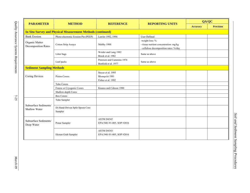
Table 7.2 Soils Methods Summary
QA/QC PARAMETER METHOD REFERENCE REPORTING UNITS
Accuracy Precision
In Situ Survey and Physical Measurement Methods
Sediment Deposition and Accretion Sediment Trap Method
Reed 1989, 1992 Hutchinson et al. 1995 Kirchner 1975 Day et al. 1999
-g/m² (Dry Sediment Basis)
Sediment Collection Tiles Pasternack and Brush 1998 Christansen et.al. 2000 Neubauer et al. 2002
-g/m² (Dry Sediment Basis)
Sediment Accretion by Feldspar Marker Technique
Reed 1992 Cahoon 1994 Cahoon et al. 1996 Steyer et al. 1995 Cahoon and Turner 1989
- g/m² (Dry Sediment Basis) - Depth (Feldspar Horizon) in mm -g/m² (dry Sediment basis
± 0.1 cm. ≤ 30%
Sediment Accretion Using Isotopic Tracers: 137Cs and 210 Pb dating
DeLaune et al. 1989 Flynn 1968
Distance (Isotopic Activity) in mm 137Cs and 210Pb activity in dpm/g
± 5 mm (Distance) ≤ 30%
Sediment Accretion Using Beryllium-7
Neubauer et al. 2002
Distance (isotopic Activity) mm 7Be Activity in dpm/g
± 5 mm (Depth) ≤ 30%
Sediment Accretion by Rare Earth Element(REE)
Knauss and Van Gent 1989 Knauss 1986
Distance (of Isotopic activity) in mm 7Be activity in dpm/g
± 5 mm (Depth) ≤ 30%
Elevation Change Sedimentation and Erosion Tables (SETs)
Boumans and Day 1993 Day 1993 Cahoon 1994
Depth in mm ± 5 mm (Depth) ≤ 30%
Rod Surface Elevation Tables
Cahoon et al. 2002b ± 5 mm (Depth)
Soil and Sediment Sam
pling Procedures Q
uality Assurance Systems Requirem
ents 7-25
March 09
QA/QC PARAMETER METHOD REFERENCE REPORTING UNITS
Accuracy Precision
In Situ Survey and Physical Measurement Methods (continued) Bank Erosion Photo-electronic Erosion Pin (PEEP) Lawler 1992, 1994 User Defined
Organic Matter Decomposition Rates Cotton Strip Assays Maltby 1988
-weight loss: % - tissue nutrient concentration: mg/kg - cellulose decomposition rates: %/day
Litter bags Weider and Lang 1982 Brock et al. 1982
Same as above
Leaf packs Peterson and Cummins 1974 Benfield et al. 1977
Same as above
Sediment Sampling Methods
Coring Devices Piston Corers Steyer et al. 1995 Blomqvist 1991 Fisher et al. 1992
Tube Corers Freeze or Cryogenic Corers Knauss and Cahoon 1990
Shallow-depth Cores
Box Corers Tube Sampler
Subsurface Sediments/ Shallow Water D) Hand-Driven Split-Spoon Core
Sampler
Subsurface Sediments/ Deep Water Ponar Sampler
ASTM D4342 EPA/540/-91-005, SOP #2016
Ekman Grab Sampler ASTM D4343 EPA/540/-91-005, SOP #2016

Soil and Sediment Sam
pling Procedures Q
uality Assurance Systems Requirem
ents 7-26
March 09
Soil Sampling Methods
Surface and Subsurface Soil Samples
Spade and Scoop EPA/540/4-91/001 EPA/625/R-93/003A ASTM D 5633
Hand Auger and Tube Sampler Method
ASTM D 1452, D 4700 FDEP DEP- SOP-001/01 FS 3000
Split-Spoon Sampler ASTM D 1586 Thin-Walled (Shelby) Tube Sampler ASTM D 1587 E) Continuous Tube Sampler ASTM D 4700 E) Direct Push Soil Sampling Method ASTM D 6282 F) EnCore™ Sampler Technique Interstitial Water (Pore water) Sampling Methods
Pore water: Ex Situ Core Section Squeezers
Lusczynski 1961 Hartman 1965 Presley et al. 1967
Nutrient Concentrations in Pore water: mg/L Salinity (Pore Water): ppt
Whole-Core Squeezers Kalil and Goldhaber 1973 Bender et al. 1987 Jahnke 1988
Nutrient Concentrations in Pore water: mg/L Salinity (Pore Water): ppt
Centrifugation Nutrient Concentrations in Pore water: mg/L Salinity (Pore Water): ppt
Suction Filtration
Mitsch and Gosselink 1993 Makemson 1972 Winger and lasier 1991 Newman and Pietro 2001
Nutrient Concentrations in Pore water: mg/L Salinity (Pore Water): ppt
Soil and Sediment Sam
pling Procedures Q
uality Assurance Systems Requirem
ents 7-27
March 09
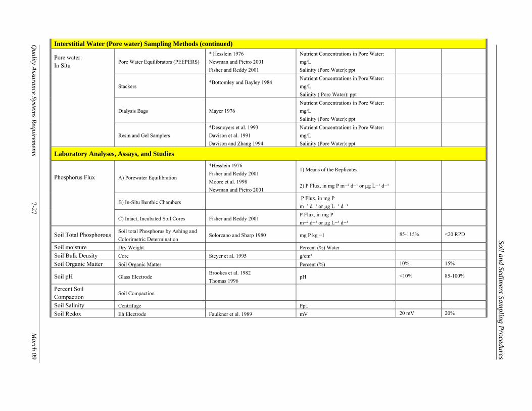
Interstitial Water (Pore water) Sampling Methods (continued)
Pore water: In Situ Pore Water Equilibrators (PEEPERS)
* Hesslein 1976 Newman and Pietro 2001 Fisher and Reddy 2001
Nutrient Concentrations in Pore Water: mg/L Salinity (Pore Water): ppt
Stackers *Bottomley and Bayley 1984
Nutrient Concentrations in Pore Water: mg/L Salinity ( Pore Water): ppt
Dialysis Bags Mayer 1976 Nutrient Concentrations in Pore Water: mg/L Salinity (Pore Water): ppt
Resin and Gel Samplers *Desnoyers et al. 1993 Davison et al. 1991 Davison and Zhang 1994
Nutrient Concentrations in Pore Water: mg/L Salinity (Pore Water): ppt
Laboratory Analyses, Assays, and Studies
Phosphorus Flux A) Porewater Equilibration
*Hesslein 1976 Fisher and Reddy 2001 Moore et al. 1998 Newman and Pietro 2001
1) Means of the Replicates 2) P Flux, in mg P m−² d−¹ or µg L−¹ d−¹
B) In-Situ Benthic Chambers P Flux, in mg P m−² d−¹ or µg L−¹ d−¹
C) Intact, Incubated Soil Cores Fisher and Reddy 2001 P Flux, in mg P m−² d−¹ or µg L−¹ d−¹
Soil Total Phosphorous Soil total Phosphorus by Ashing and Colorimetric Determination
Solorzano and Sharp 1980 mg P kg −1 85-115% <20 RPD
Soil moisture Dry Weight Percent (%) Water
Soil Bulk Density Core Steyer et al. 1995 g/cm³
Soil Organic Matter Soil Organic Matter Percent (%) 10% 15%
Soil pH Glass Electrode Brookes et al. 1982 Thomas 1996
pH <10% 85-100%
Percent Soil Compaction Soil Compaction
Soil Salinity Centrifuge Ppt.
Soil Redox Eh Electrode Faulkner et al. 1989 mV 20 mV 20%

Soil and Sediment Sam
pling Procedures Q
uality Assurance Systems Requirem
ents 7-28
March 09
Laboratory Analyses, Assays, and Studies (continued) Soil/Sediment Oxygen Demand (SOD) Dissolved Oxygen Probe
White and Reddy 2001 APHA 1992
02/g*d
Soil Oxygen Content Diffusion chamber *Patrick 1977 Carter et al. 1984a Faulkner et al. 1989
Soil Phosphorus Ashing Method/ Acid Colorimetric Procedure
Anderson 1976 Kuo 1996 Sommers and Nelson 1972
Soluble P Ascorbic Acid Technique Method 365.3 USEPA 1979 Inorganic P Extraction with N HCL mg/Kg Total Carbon (TC), Total Nitrogen (TN), and Total Sulfur (TS)
Carlo-Erba NA 1500 CNS Analyzer mg/Kg
Total Nitrogen Kjeldahl method Bremmer 1965 mg/Kg
Extractable NH4+ Automated Colorimetric procedure Mulvaney 1996 Method 350.1, USEPA 1993b Wright and Reddy 2001
mg/g
Soil Sulfate Ion Chromatography Method 300.0, USEPA, 1993a Sulfate (Porewater): mg/L Sulfate (Water-extractable): mg/Kg
Soil Sulfide Electrodes Steyer et al. 1995 mg/g 1 ppm 25%
Soil Respiration; Anaerobic and Aerobic
Thermal Conductivity GC Flame Ionization Detection Detector
D’Angelo and Reddy 1999
Aerobic Respiration (Upland Soils) Gas Chromatograph
Soil Microbial Biomass C Fumigation Extraction
Vance et al. 1987 White and Reddy 2001 White and Reddy 2000 Sparling et al. 1990
g/kg
Soil Microbial Biomass N Fumigation Extraction
Brookes et al. 1985 White and Reddy 2001
mg/kg
Soil Microbial Biomass P Fumigation Extraction
Hedley and Stewart 1982 Ivanoff 1998; Wright & Reddy 2001
mg/kg

Soil and Sediment Sampling Procedures
Quality Assurance Systems Requirements 7-29 March 09
Table 7.3 Advantages and disadvantages of several methods for isolating sediment pore water for chemical testing (from Carr et al. 2001)
Method Advantages Disadvantages
Peep
er (i
n si
tu)
Pore water chemistry is measured without significant disturbance of the in situ equilibrium conditions. Reduced sample manipulation Reduced sampling influences on the oxidation state of metals Eliminated potential for loss of volatile substances, such as H2S, and high Henry’s law constant HOCs, which occur with ex situ methods Use of a dialysis membrane eliminates the post-retrieval pore water filtration pH and redox conditions are relatively unaltered, minimizing changes in pH and oxygen-sensitive species (such as metals)
Operates well for inorganic constituents (e.g., divalent metals, NH3), but their utility for accurately sampling highly hydrophobic organic compounds is poorly defined (i.e., sorption of hydrophobic compounds onto the sampler, the dialysis membrane, or onto the fouling organisms associated with the membrane, depending on the length of deployment, could artificially reduce pore water contaminant concentrations). An extended equilibration time in the field is required (generally 15 to 20 days), resulting in the need for 2 field trips: one for peeper deployment and one for peeper retrieval. Sample volumes are limited, generally to less than 10 mL. Larger peepers are limited to very porous substrates. Uncontaminated water inside newly deployed peeper cells could effectively dilute pore water contaminant concentrations in low-porosity sediments. Samples must be collected from peepers immediately upon retrieval, resulting in a longer holding time for pore water outside of its natural matrix prior to toxicity testing. A high degree of technical competence and effort is required for proper use. Use in deeper water requires diving. In situ methods are often not practical for deep waters or high-energy situations
Suct
ion
(in si
tu)
Easy and low-technology operation; use of inexpensive equipment Is suitable for use with a wide variety of sediment textures Procedure can generate large volumes of pore water
Potential sorption of metals and HOCs on ‘filter’ Some clogging may occur in small-to-medium particle-sized sediments and slow down the pore water extraction process. Collection of pore waters from non-targeted depths (e.g., overlying water) may occur when collection is conducted in situ. Degassing of pore water may occur.

Soil and Sediment Sampling Procedures
Quality Assurance Systems Requirements 7-30 March 09
Method Advantages Disadvantages C
entri
fuga
tion
(ex
situ
) Several variables (e.g., duration, speed) can be varied to optimize operation Procedure can generate large volumes of pore water Functions with fine-to-medium particle-sized sediments Easy operation
Labor intensive (e.g., sediment loading); requires a refrigerated centrifuge with large tube capacity Lack of a generic methodology Potential sorption of HOCs to centrifuge tube Lysis of cells during spinning Does not function in sandy sediments
Pres
suriz
atio
n (e
x si
tu)
Can be used with highly bioturbated sediments without lysis of cells Procedure can generate large volumes of pore water Can be used with a wide variety of sediment textures
Potential loss of HOCs on filter Changes in dissolved gasses may occur
Related Documents