1 7. Stress Transformation Chapter Objectives Navigate between rectilinear co-ordinate systems for stress components Determine principal stresses and maximum in-plane shear stress 7. Stress Transformation 2 CHAPTER OUTLINE 1. Plane-Stress Transformation 2. General Equations of Plane Stress Transformation 3. Principal Stresses and Maximum In-Plane Shear Stress 4. Mohr’s Circle – Plane Stress 5. Stress in Shafts Due to Axial Load and Torsion

Welcome message from author
This document is posted to help you gain knowledge. Please leave a comment to let me know what you think about it! Share it to your friends and learn new things together.
Transcript

1
7. Stress Transformation
Chapter Objectives
Navigate between rectilinear co-ordinate systems for
stress components
Determine principal stresses and maximum in-plane
shear stress
7. Stress Transformation
2
CHAPTER OUTLINE
1. Plane-Stress Transformation
2. General Equations of Plane Stress
Transformation
3. Principal Stresses and Maximum In-Plane
Shear Stress
4. Mohr’s Circle – Plane Stress
5. Stress in Shafts Due to Axial Load and Torsion

2
7. Stress Transformation
5
9.1 PLANE-STRESS TRANSFORMATION
• General state of stress at a pt is characterized by
six independent normal and shear stress
components.
• In practice, approximations and simplifications are
done to reduce the stress components to a single
plane.
7. Stress Transformation
6
• The material is then said to be
subjected to plane stress.
• For general state of plane stress at a
pt, we represent it via normal-stress
components, x, y and shear-stress
component xy.
• Thus, state of plane stress at the pt is
uniquely represented by three
components acting on an element
that has a specific orientation at
that pt.
9.1 PLANE-STRESS TRANSFORMATION
7. Stress Transformation
7
• The most general state of stress at a
point may be represented by 6
components,
),, :(Note
stresses shearing,,
stresses normal,,
xzzxzyyzyxxy
zxyzxy
zyx
• Same state of stress is represented by a
different set of components if axes are
rotated.
9.1 PLANE-STRESS TRANSFORMATION
7. Stress Transformation
8
• Transforming stress components from one
orientation to the other is similar in concept to how
we transform force components from one system of
axes to the other.
• Note that for stress-component transformation, we
need to account for
– the magnitude and direction of each stress
component, and
– the orientation of the area upon which each
component acts.
9.1 PLANE-STRESS TRANSFORMATION
3
7. Stress Transformation
9
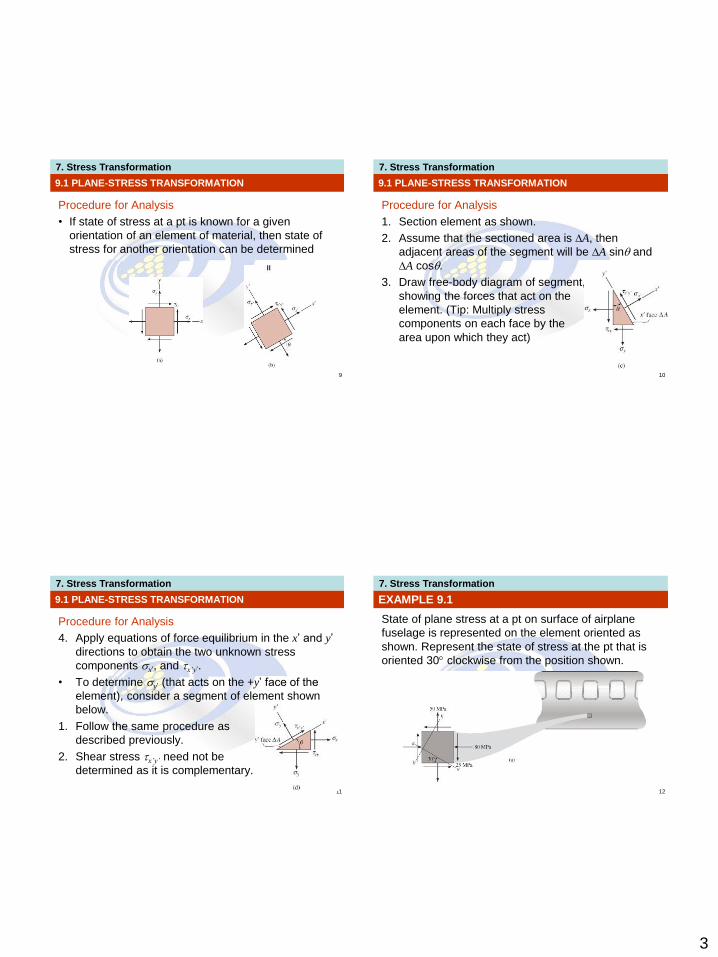
Procedure for Analysis
• If state of stress at a pt is known for a given
orientation of an element of material, then state of
stress for another orientation can be determined
9.1 PLANE-STRESS TRANSFORMATION
7. Stress Transformation
10
Procedure for Analysis
1. Section element as shown.
2. Assume that the sectioned area is ∆A, then
adjacent areas of the segment will be ∆A sin and
∆A cos.
3. Draw free-body diagram of segment,
showing the forces that act on the
element. (Tip: Multiply stress
components on each face by the
area upon which they act)
9.1 PLANE-STRESS TRANSFORMATION
7. Stress Transformation
11
Procedure for Analysis
4. Apply equations of force equilibrium in the x’ and y’
directions to obtain the two unknown stress
components x’, and x’y’.
• To determine y’ (that acts on the +y’ face of the
element), consider a segment of element shown
below.
1. Follow the same procedure as
described previously.
2. Shear stress x’y’ need not be
determined as it is complementary.
9.1 PLANE-STRESS TRANSFORMATION
7. Stress Transformation
12
EXAMPLE 9.1
State of plane stress at a pt on surface of airplane
fuselage is represented on the element oriented as
shown. Represent the state of stress at the pt that is
oriented 30 clockwise from the position shown.

4
7. Stress Transformation
13
EXAMPLE 9.1 (SOLN)
CASE A (a-a section)
• Section element by line a-a and
remove bottom segment.
• Assume sectioned (inclined)
plane has an area of ∆A,
horizontal and vertical planes
have area as shown.
• Free-body diagram of
segment is also shown.
7. Stress Transformation
14
EXAMPLE 9.1 (SOLN)
• Apply equations of force equilibrium
in the x’ and y’ directions (to avoid
simultaneous solution for the two
unknowns)
+ Fx’ = 0;
'
'
50 cos30 cos30
25 cos30 sin 30 80 sin 30 sin 30
25 sin 30 cos30 0
4.15 MPa
x
x
A A
A A
A
7. Stress Transformation
15
EXAMPLE 9.1 (SOLN)
+ Fy’ = 0;
• Since x’ is negative, it acts
in the opposite direction
we initially assumed.
MPa8.68
030sin30sin25
30cos30sin8030cos30cos25
30sin30cos50
''
''
yx
yx
A
AA
AA
7. Stress Transformation
16
EXAMPLE 9.1 (SOLN)
CASE B (b-b section)
• Repeat the procedure to obtain
the stress on the perpendicular
plane b-b.
• Section element as shown
on the upper right.
• Orientate the +x’ axis
outward, perpendicular to
the sectioned face, with
the free-body diagram
as shown.
5
7. Stress Transformation
17
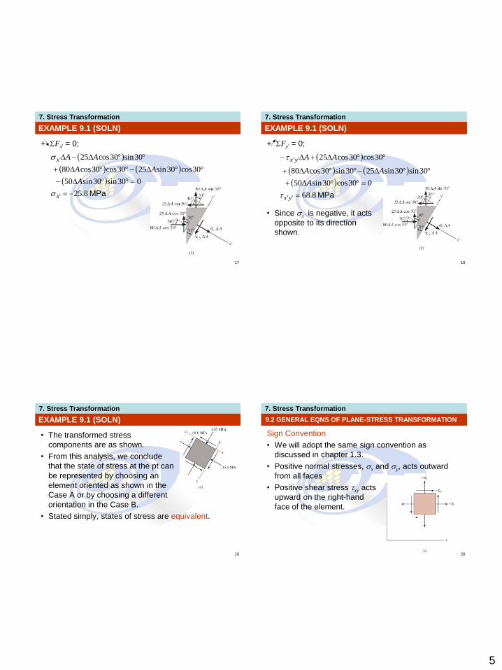
EXAMPLE 9.1 (SOLN)
+ Fx’ = 0;
MPa8.25
030sin30sin50
30cos30sin2530cos30cos80
30sin30cos25
'
'
x
x
A
AA
AA
7. Stress Transformation
18
EXAMPLE 9.1 (SOLN)
+ Fy’ = 0;
• Since x’ is negative, it acts
opposite to its direction
shown.
MPa8.68
030cos30sin50
30sin30sin2530sin30cos80
30cos30cos25
''
''
yx
yx
A
AA
AA
7. Stress Transformation
19
EXAMPLE 9.1 (SOLN)
• The transformed stress
components are as shown.
• From this analysis, we conclude
that the state of stress at the pt can
be represented by choosing an
element oriented as shown in the
Case A or by choosing a different
orientation in the Case B.
• Stated simply, states of stress are equivalent.
7. Stress Transformation
20
9.2 GENERAL EQNS OF PLANE-STRESS TRANSFORMATION
Sign Convention
• We will adopt the same sign convention as
discussed in chapter 1.3.
• Positive normal stresses, x and y, acts outward
from all faces
• Positive shear stress xy acts
upward on the right-hand
face of the element.

6
7. Stress Transformation
21
9.2 GENERAL EQNS OF PLANE-STRESS TRANSFORMATION
Sign Convention
• The orientation of the inclined plane is determined
using the angle .
• Establish a positive x’ and y’ axes using the right-
hand rule.
• Angle is positive if it
moves counterclockwise
from the +x axis to
the +x’ axis.
7. Stress Transformation
22
9.2 GENERAL EQNS OF PLANE-STRESS TRANSFORMATION
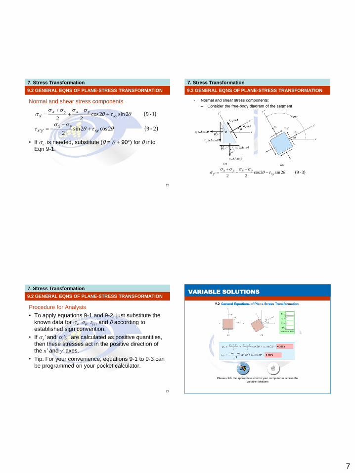
Normal and shear stress components
• Section element as shown.
• Assume sectioned area is ∆A.
• Free-body diagram of element
is shown.
7. Stress Transformation
23
9.2 GENERAL EQNS OF PLANE-STRESS TRANSFORMATION
Normal and shear stress components
• Apply equations of force
equilibrium to determine
unknown stress components:
+ Fx’ = 0;
cossin2sincos
0coscos
sincossinsin
cossin
22'
'
xyyxx
x
xyy
xyx
A
AA
AA
7. Stress Transformation
24
9.2 GENERAL EQNS OF PLANE-STRESS TRANSFORMATION
Normal and shear stress components
+ Fy’ = 0;
• Simplify the above two equations using trigonometric identities sin2 = 2 sin cos, sin2 = (1 cos2)/2, and cos2 =(1+cos2)/2.
22''
''
sincoscossin
0sincos
coscoscossin
sinsin
xyyxyx
x
xyy
xyyx
A
AA
AA
7
7. Stress Transformation
25
9.2 GENERAL EQNS OF PLANE-STRESS TRANSFORMATION
Normal and shear stress components
• If y’ is needed, substitute ( = + 90) for into
Eqn 9-1.
292cos2sin2
'' -
xyyx
yx
192sin2cos22
' -
xyyxyx
x
7. Stress Transformation
• Normal and shear stress components:
– Consider the free-body diagram of the segment
9.2 GENERAL EQNS OF PLANE-STRESS TRANSFORMATION
392sin2cos22
' -
xyyxyx
y
7. Stress Transformation
27
9.2 GENERAL EQNS OF PLANE-STRESS TRANSFORMATION
Procedure for Analysis
• To apply equations 9-1 and 9-2, just substitute the
known data for x, y, xy, and according to
established sign convention.
• If x’ and x’y’ are calculated as positive quantities,
then these stresses act in the positive direction of
the x’ and y’ axes.
• Tip: For your convenience, equations 9-1 to 9-3 can
be programmed on your pocket calculator.
7. Stress Transformation VARIABLE SOLUTIONS
Please click the appropriate icon for your computer to access the
variable solutions
8
7. Stress Transformation
29
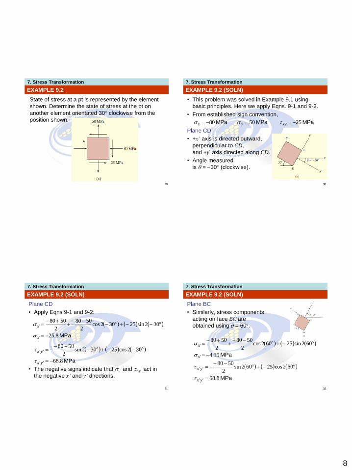
EXAMPLE 9.2
State of stress at a pt is represented by the element
shown. Determine the state of stress at the pt on
another element orientated 30 clockwise from the
position shown.
7. Stress Transformation
30
EXAMPLE 9.2 (SOLN)
• This problem was solved in Example 9.1 using
basic principles. Here we apply Eqns. 9-1 and 9-2.
• From established sign convention,
Plane CD
• +x’ axis is directed outward,
perpendicular to CD,
and +y’ axis directed along CD.
• Angle measured
is = 30 (clockwise).
MPaMPaMPa 255080 xyyx
7. Stress Transformation
31
EXAMPLE 9.2 (SOLN)
Plane CD
• Apply Eqns 9-1 and 9-2:
• The negative signs indicate that x’ and x’y’ act in
the negative x’ and y’ directions.
MPa8.25
302sin25302cos2
5080
2
5080
'
'
x
x
MPa8.68
302cos25302sin2
5080
''
''
yx
yx
7. Stress Transformation
32
EXAMPLE 9.2 (SOLN)
Plane BC
• Similarly, stress components
acting on face BC are
obtained using = 60.
MPa15.4
602sin25602cos2
5080
2
5080
'
'
x
x
MPa8.68
602cos25602sin2
5080
''
''
yx
yx
9
7. Stress Transformation
33
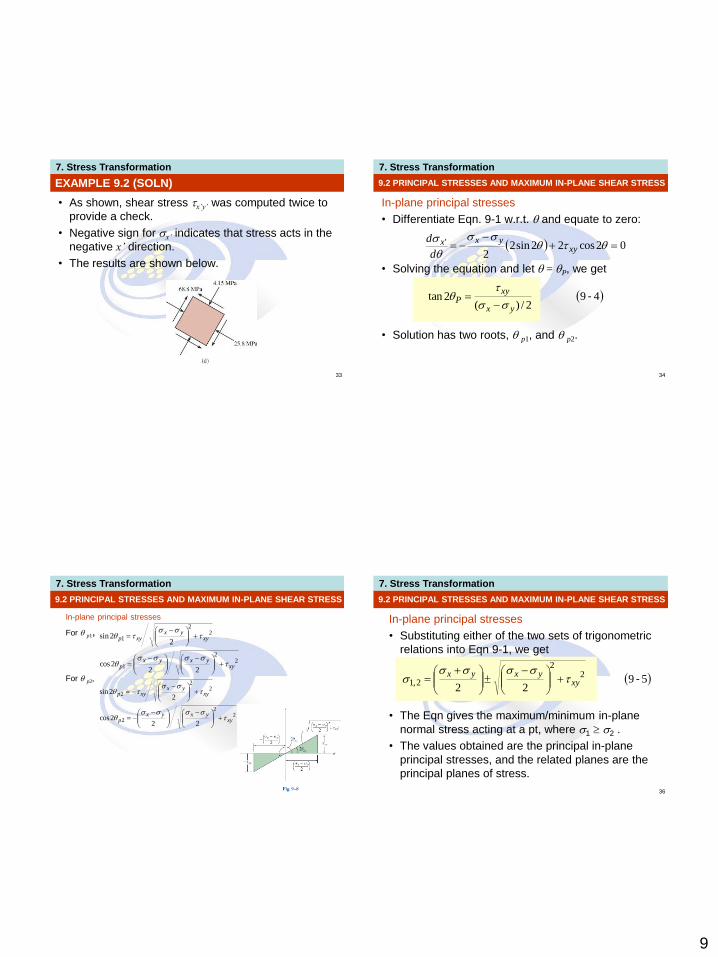
EXAMPLE 9.2 (SOLN)
• As shown, shear stress x’y’ was computed twice to
provide a check.
• Negative sign for x’ indicates that stress acts in the
negative x’ direction.
• The results are shown below.
7. Stress Transformation
34
9.2 PRINCIPAL STRESSES AND MAXIMUM IN-PLANE SHEAR STRESS
In-plane principal stresses
• Differentiate Eqn. 9-1 w.r.t. and equate to zero:
• Solving the equation and let = P, we get
• Solution has two roots, p1, and p2.
02cos22sin22
'
xy
yxx
d
d
492/)(
2tan -yx
xyP
7. Stress Transformation
35
9.2 PRINCIPAL STRESSES AND MAXIMUM IN-PLANE SHEAR STRESS
In-plane principal stresses
For p1,
For p2,
22
1
22
1
222cos
22sin
xyyxyx
p
xyyx
xyp
22
2
22
2
222cos
22sin
xyyxyx
p
xyyx
xyp
7. Stress Transformation
36
9.2 PRINCIPAL STRESSES AND MAXIMUM IN-PLANE SHEAR STRESS
In-plane principal stresses
• Substituting either of the two sets of trigonometric
relations into Eqn 9-1, we get
• The Eqn gives the maximum/minimum in-plane
normal stress acting at a pt, where 1 2 .
• The values obtained are the principal in-plane
principal stresses, and the related planes are the
principal planes of stress.
5922
22
2,1 -xyyxyx
10
7. Stress Transformation
37
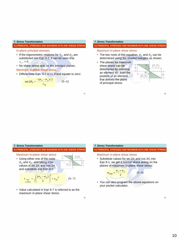
9.2 PRINCIPAL STRESSES AND MAXIMUM IN-PLANE SHEAR STRESS
In-plane principal stresses
• If the trigonometric relations for p1 and p2 are
substituted into Eqn 9-2, it can be seen that
x’y’ = 0.
• No shear stress acts on the principal planes.
Maximum in-plane shear stress
• Differentiate Eqn. 9-2 w.r.t. and equate to zero:
692/)(
2tan -xy
yxS
7. Stress Transformation
38
9.2 PRINCIPAL STRESSES AND MAXIMUM IN-PLANE SHEAR STRESS
Maximum in-plane shear stress
• The two roots of this equation, s1 and s2 can be
determined using the shaded triangles as shown.
• The planes for maximum
shear stress can be
determined by orienting
an element 45 from the
position of an element
that defines the plane
of principal stress.
7. Stress Transformation
39
9.2 PRINCIPAL STRESSES AND MAXIMUM IN-PLANE SHEAR STRESS
Maximum in-plane shear stress
• Using either one of the roots
s1 and s2, and taking trigo
values of sin 2s and cos 2s
and substitute into Eqn 9-2:
• Value calculated in Eqn 9-7 is referred to as the
maximum in-plane shear stress.
792
)( 22
-plane-in
max xyyx
7. Stress Transformation
40
Maximum in-plane shear stress
• Substitute values for sin 2s and cos 2s into
Eqn 9-1, we get a normal stress acting on the
planes of maximum in-plane shear stress:
• You can also program the above equations on
your pocket calculator.
9.2 PRINCIPAL STRESSES AND MAXIMUM IN-PLANE SHEAR STRESS
892
-yx
avg

11
7. Stress Transformation
41
IMPORTANT
• Principals stresses represent the maximum and minimum normal stresses at the pt.
• When state of stress is represented by principal stresses, no shear stress will act on element.
• State of stress at the pt can also be represented in terms of the maximum in-plane shear stress. An average normal stress will also act on the element.
• Element representing the maximum in-plane shear stress with associated average normal stresses is oriented 45 from element represented principal stresses.
9.2 PRINCIPAL STRESSES AND MAXIMUM IN-PLANE SHEAR STRESS
7. Stress Transformation
42
EXAMPLE 9.3
When torsional loading T is applied to bar, it produces
a state of pure shear stress in the material. Determine
(a) the maximum in-plane shear stress and
associated average normal stress, and (b) the
principal stress.
7. Stress Transformation
43
EXAMPLE 9.3 (SOLN)
• From established sign convention:
Maximum in-plane shear stress
• Apply Eqns 9-7 and 9-8,
xyyx 00
220
2
)( 22
xyyx
plane-in
max
02
00
2
yxavg
7. Stress Transformation
44
EXAMPLE 9.3 (SOLN)
Maximum in-plane shear stress
• As expected, maximum in-plane shear stress
represented by element shown initially.
• Experimental results show that materials that are
ductile will fail due to shear stress. Thus, with a
torque applied to a bar
made from mild steel,
the maximum in-plane
shear stress will cause
failure as shown.
12
7. Stress Transformation
45
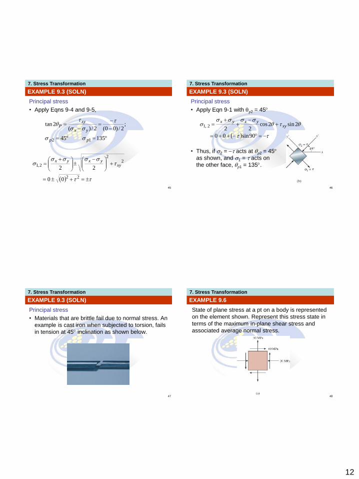
EXAMPLE 9.3 (SOLN)
Principal stress
• Apply Eqns 9-4 and 9-5,
13545
;2/)00(2/)(
2tan
12 pp
yx
xyP
22
22
2,1
00
22xy
yxyx
7. Stress Transformation
46
EXAMPLE 9.3 (SOLN)
Principal stress
• Apply Eqn 9-1 with p2 = 45
• Thus, if 2 = acts at p2 = 45
as shown, and 1 = acts on
the other face, p1 = 135.
90sin00
2sin2cos22
2,1 xyyxyx
7. Stress Transformation
47
EXAMPLE 9.3 (SOLN)
Principal stress
• Materials that are brittle fail due to normal stress. An
example is cast iron when subjected to torsion, fails
in tension at 45 inclination as shown below.
7. Stress Transformation
48
EXAMPLE 9.6
State of plane stress at a pt on a body is represented
on the element shown. Represent this stress state in
terms of the maximum in-plane shear stress and
associated average normal stress.
13
7. Stress Transformation
49
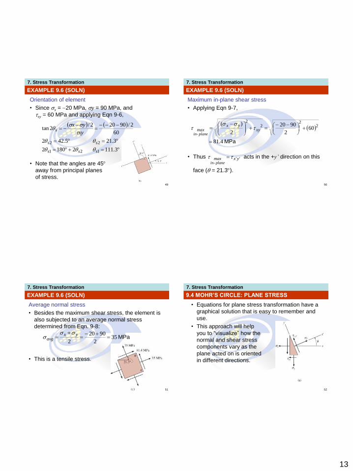
EXAMPLE 9.6 (SOLN)
Orientation of element
• Since x = 20 MPa, y = 90 MPa, and
xy = 60 MPa and applying Eqn 9-6,
• Note that the angles are 45
away from principal planes
of stress.
3.11121802
3.215.422
60
2/90202/2tan
121
22
sss
ss
sxy
yx
7. Stress Transformation
50
EXAMPLE 9.6 (SOLN)
Maximum in-plane shear stress
• Applying Eqn 9-7,
• Thus acts in the +y’ direction on this
face ( = 21.3).
MPa4.81
602
9020
2
)( 22
22
xy
yxmax
lanep-in
''yxmaxlanep-in
7. Stress Transformation
51
EXAMPLE 9.6 (SOLN)
Average normal stress
• Besides the maximum shear stress, the element is
also subjected to an average normal stress
determined from Eqn. 9-8:
• This is a tensile stress.
MPa352
9020
2
yxavg
7. Stress Transformation
52
• Equations for plane stress transformation have a
graphical solution that is easy to remember and
use.
• This approach will help
you to “visualize” how the
normal and shear stress
components vary as the
plane acted on is oriented
in different directions.
9.4 MOHR’S CIRCLE: PLANE STRESS
14
7. Stress Transformation
53
• Eqns 9-1 and 9-2 are rewritten as
• Parameter can be eliminated by squaring each
eqn and adding them together.
9.4 MOHR’S CIRCLE: PLANE STRESS
1092cos2sin2
'' -
xyyx
yx
992sin2cos22
' -
xyyxyx
x
xyyx
yxyx
x2
2
''2
2
'22
7. Stress Transformation
54
• If x, y, xy are known constants, thus we compact
the Eqn as,
9.4 MOHR’S CIRCLE: PLANE STRESS
1292
2
119
22
2''
22'
-
where
-
xyyx
yxavg
yxavgx
R
R
7. Stress Transformation
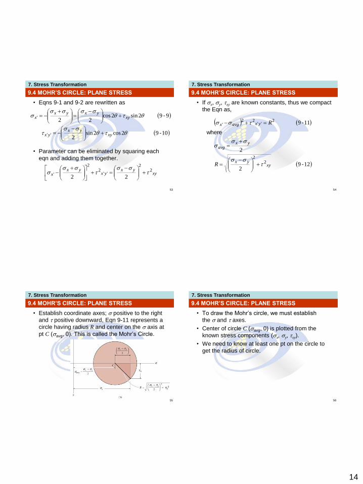
55
• Establish coordinate axes; positive to the right
and positive downward, Eqn 9-11 represents a
circle having radius R and center on the axis at
pt C (avg, 0). This is called the Mohr’s Circle.
9.4 MOHR’S CIRCLE: PLANE STRESS
7. Stress Transformation
56
• To draw the Mohr’s circle, we must establish
the and axes.
• Center of circle C (avg, 0) is plotted from the
known stress components (x, y, xy).
• We need to know at least one pt on the circle to
get the radius of circle.
9.4 MOHR’S CIRCLE: PLANE STRESS
15
7. Stress Transformation
57
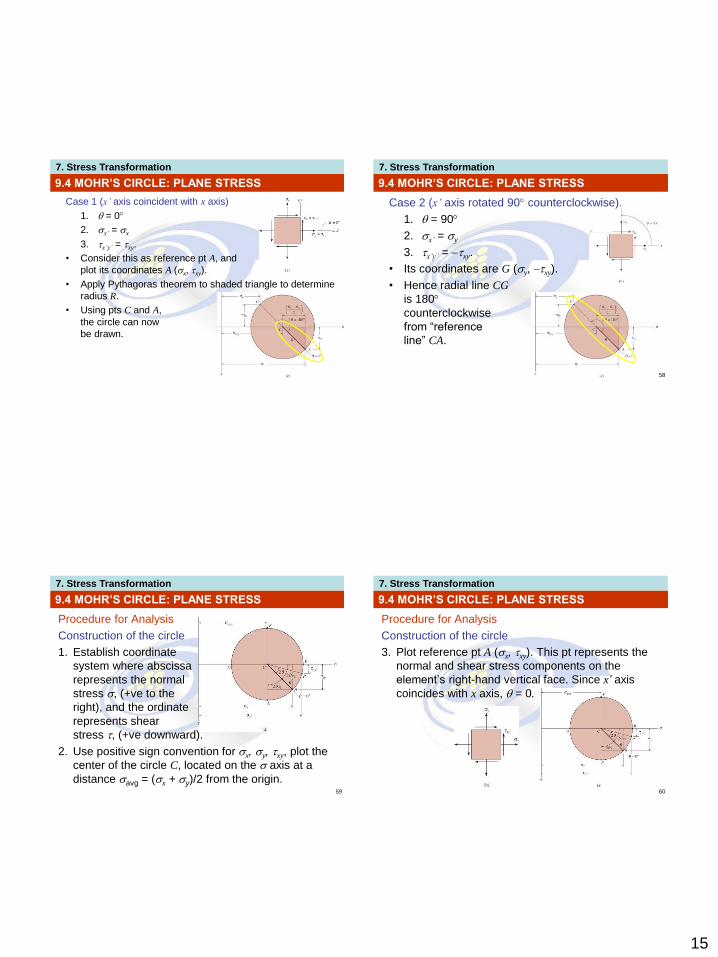
Case 1 (x’ axis coincident with x axis)
1. = 0
2. x’ = x
3. x’y’ = xy.
• Consider this as reference pt A, and
plot its coordinates A (x, xy).
• Apply Pythagoras theorem to shaded triangle to determine
radius R.
• Using pts C and A,
the circle can now
be drawn.
9.4 MOHR’S CIRCLE: PLANE STRESS
7. Stress Transformation
58
Case 2 (x’ axis rotated 90 counterclockwise)
1. = 90
2. x’ = y
3. x’y’ = xy.
• Its coordinates are G (y, xy).
• Hence radial line CG
is 180
counterclockwise
from “reference
line” CA.
9.4 MOHR’S CIRCLE: PLANE STRESS
7. Stress Transformation
59
Procedure for Analysis
Construction of the circle
1. Establish coordinate
system where abscissa
represents the normal
stress , (+ve to the
right), and the ordinate
represents shear
stress , (+ve downward).
2. Use positive sign convention for x, y, xy, plot the
center of the circle C, located on the axis at a
distance avg = (x + y)/2 from the origin.
9.4 MOHR’S CIRCLE: PLANE STRESS
7. Stress Transformation
60
Procedure for Analysis
Construction of the circle
3. Plot reference pt A (x, xy). This pt represents the
normal and shear stress components on the
element’s right-hand vertical face. Since x’ axis
coincides with x axis, = 0.
9.4 MOHR’S CIRCLE: PLANE STRESS
16
7. Stress Transformation
61
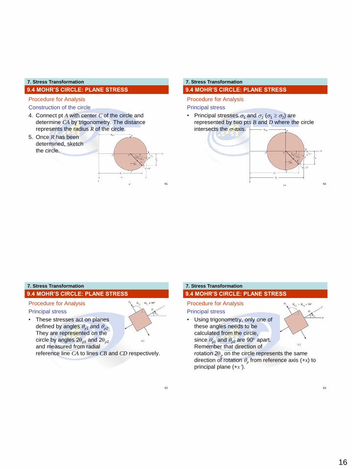
Procedure for Analysis
Construction of the circle
4. Connect pt A with center C of the circle and
determine CA by trigonometry. The distance
represents the radius R of the circle.
5. Once R has been
determined, sketch
the circle.
9.4 MOHR’S CIRCLE: PLANE STRESS
7. Stress Transformation
62
Procedure for Analysis
Principal stress
• Principal stresses 1 and 2 (1 2) are
represented by two pts B and D where the circle
intersects the -axis.
9.4 MOHR’S CIRCLE: PLANE STRESS
7. Stress Transformation
63
Procedure for Analysis
Principal stress
• These stresses act on planes
defined by angles p1 and p2.
They are represented on the
circle by angles 2p1 and 2p2
and measured from radial
reference line CA to lines CB and CD respectively.
9.4 MOHR’S CIRCLE: PLANE STRESS
7. Stress Transformation
64
Procedure for Analysis
Principal stress
• Using trigonometry, only one of
these angles needs to be
calculated from the circle,
since p1 and p2 are 90 apart.
Remember that direction of
rotation 2p on the circle represents the same
direction of rotation p from reference axis (+x) to
principal plane (+x’).
9.4 MOHR’S CIRCLE: PLANE STRESS
17
7. Stress Transformation
65
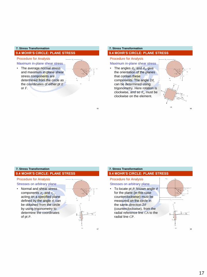
Procedure for Analysis
Maximum in-plane shear stress
• The average normal stress
and maximum in-plane shear
stress components are
determined from the circle as
the coordinates of either pt E
or F.
9.4 MOHR’S CIRCLE: PLANE STRESS
7. Stress Transformation
66
Procedure for Analysis
Maximum in-plane shear stress
• The angles s1 and s2 give
the orientation of the planes
that contain these
components. The angle 2s
can be determined using
trigonometry. Here rotation is
clockwise, and so s1 must be
clockwise on the element.
9.4 MOHR’S CIRCLE: PLANE STRESS
7. Stress Transformation
67
Procedure for Analysis
Stresses on arbitrary plane
• Normal and shear stress
components x’ and x’y’
acting on a specified plane
defined by the angle , can
be obtained from the circle
by using trigonometry to
determine the coordinates
of pt P.
9.4 MOHR’S CIRCLE: PLANE STRESS
7. Stress Transformation
68
Procedure for Analysis
Stresses on arbitrary plane
• To locate pt P, known angle
for the plane (in this case
counterclockwise) must be
measured on the circle in
the same direction 2
(counterclockwise), from the
radial reference line CA to the
radial line CP.
9.4 MOHR’S CIRCLE: PLANE STRESS
18
7. Stress Transformation
69
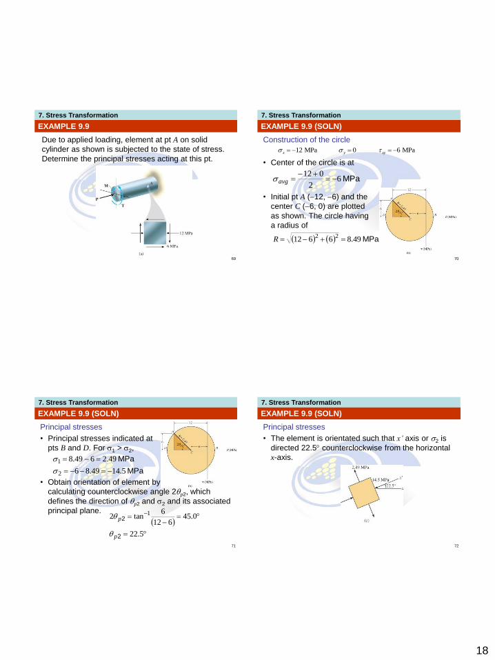
EXAMPLE 9.9
Due to applied loading, element at pt A on solid
cylinder as shown is subjected to the state of stress.
Determine the principal stresses acting at this pt.
7. Stress Transformation
70
EXAMPLE 9.9 (SOLN)
Construction of the circle
• Center of the circle is at
• Initial pt A (12, 6) and the
center C (6, 0) are plotted
as shown. The circle having
a radius of
12 MPa 0 6 MPax y xy
MPa62
012
avg
MPa49.8661222R
7. Stress Transformation
71
EXAMPLE 9.9 (SOLN)
Principal stresses
• Principal stresses indicated at
pts B and D. For 1 > 2,
• Obtain orientation of element by
calculating counterclockwise angle 2p2, which
defines the direction of p2 and 2 and its associated
principal plane.
MPa
MPa
5.1449.86
49.2649.8
2
1
5.22
0.45612
6tan2 1
2
2
p
p
7. Stress Transformation
72
EXAMPLE 9.9 (SOLN)
Principal stresses
• The element is orientated such that x’ axis or 2 is
directed 22.5 counterclockwise from the horizontal
x-axis.

19
7. Stress Transformation
73
EXAMPLE 9.10
State of plane stress at a pt is shown on the element.
Determine the maximum in-plane shear stresses and
the orientation of the element upon which they act.
7. Stress Transformation
74
EXAMPLE 9.10 (SOLN)
Construction of circle
• Establish the , axes as shown below. Center of
circle C located on the -axis, at the pt:
MPaMPaMPa 609020 xyyx
MPa352
9020
avg
7. Stress Transformation
75
EXAMPLE 9.10 (SOLN)
Construction of circle
• Pt C and reference pt A (20, 60) are plotted. Apply
Pythagoras theorem to shaded triangle to get
circle’s radius CA,
MPa4.81
556022
R
R
7. Stress Transformation
76
EXAMPLE 9.10 (SOLN)
Maximum in-plane shear stress
• Maximum in-plane shear stress and average normal
stress are identified by pt E or F on the circle. In
particular, coordinates of pt E (35, 81.4) gives
MPa
MPaplane-in
max
35
4.81
avg
20
7. Stress Transformation
77
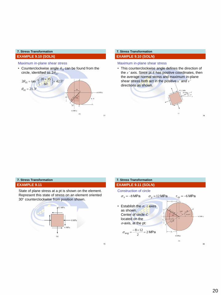
EXAMPLE 9.10 (SOLN)
Maximum in-plane shear stress
• Counterclockwise angle s1 can be found from the
circle, identified as 2s1.
3.21
5.4260
3520tan2
1
11
s
s
7. Stress Transformation
78
EXAMPLE 9.10 (SOLN)
Maximum in-plane shear stress
• This counterclockwise angle defines the direction of
the x’ axis. Since pt E has positive coordinates, then
the average normal stress and maximum in-plane
shear stress both act in the positive x’ and y’
directions as shown.
7. Stress Transformation
79
EXAMPLE 9.11
State of plane stress at a pt is shown on the element.
Represent this state of stress on an element oriented
30 counterclockwise from position shown.
7. Stress Transformation
80
EXAMPLE 9.11 (SOLN)
Construction of circle
• Establish the , axes
as shown.
Center of circle C
located on the
-axis, at the pt:
MPaMPaMPa 6128 xyyx
MPa22
128
avg
21
7. Stress Transformation
81
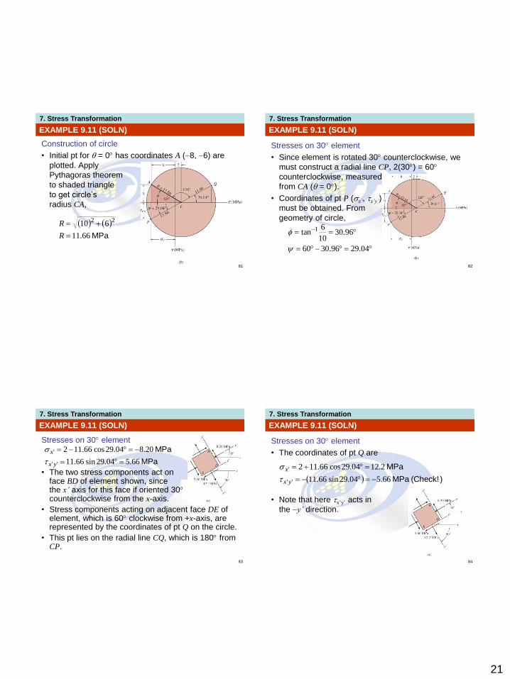
EXAMPLE 9.11 (SOLN)
Construction of circle
• Initial pt for = 0 has coordinates A (8, 6) are
plotted. Apply
Pythagoras theorem
to shaded triangle
to get circle’s
radius CA,
MPa66.11
61022
R
R
7. Stress Transformation
82
EXAMPLE 9.11 (SOLN)
Stresses on 30 element
• Since element is rotated 30 counterclockwise, we
must construct a radial line CP, 2(30) = 60
counterclockwise, measured
from CA ( = 0).
• Coordinates of pt P (x’, x’y’)
must be obtained. From
geometry of circle,
04.2996.3060
96.3010
6tan 1
7. Stress Transformation
83
EXAMPLE 9.11 (SOLN)
Stresses on 30 element
• The two stress components act on face BD of element shown, since the x’ axis for this face if oriented 30 counterclockwise from the x-axis.
• Stress components acting on adjacent face DE of element, which is 60 clockwise from +x-axis, are represented by the coordinates of pt Q on the circle.
• This pt lies on the radial line CQ, which is 180 from CP.
MPa
MPa
66.504.29sin66.11
20.804.29cos66.112
''
'
yx
x
7. Stress Transformation
84
EXAMPLE 9.11 (SOLN)
Stresses on 30 element
• The coordinates of pt Q are
• Note that here x’y’ acts in
the y’ direction.
)(Check!MPa
MPa
66.504.29sin66.11
2.1204.29cos66.112
''
'
yx
x
22
7. Stress Transformation
85
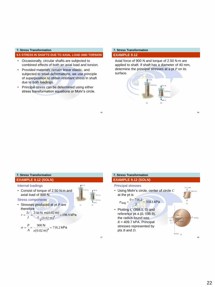
• Occasionally, circular shafts are subjected to
combined effects of both an axial load and torsion.
• Provided materials remain linear elastic, and
subjected to small deformations, we use principle
of superposition to obtain resultant stress in shaft
due to both loadings.
• Principal stress can be determined using either
stress transformation equations or Mohr’s circle.
9.5 STRESS IN SHAFTS DUE TO AXIAL LOAD AND TORSION
7. Stress Transformation
86
EXAMPLE 9.12
Axial force of 900 N and torque of 2.50 Nm are
applied to shaft. If shaft has a diameter of 40 mm,
determine the principal stresses at a pt P on its
surface.
7. Stress Transformation
87
EXAMPLE 9.12 (SOLN)
Internal loadings
• Consist of torque of 2.50 Nm and
axial load of 900 N.
Stress components
• Stresses produced at pt P are
therefore
kPa
m
mmN9.198
02.02
02.050.24
J
Tc
kPa
m
N2.716
02.0
9004
A
P
7. Stress Transformation
88
EXAMPLE 9.12 (SOLN)
Principal stresses
• Using Mohr’s circle, center of circle C
at the pt is
• Plotting C (358.1, 0) and
reference pt A (0, 198.9),
the radius found was
R = 409.7 kPA. Principal
stresses represented by
pts B and D.
kPaavg 1.3582
2.7160
23
7. Stress Transformation
89
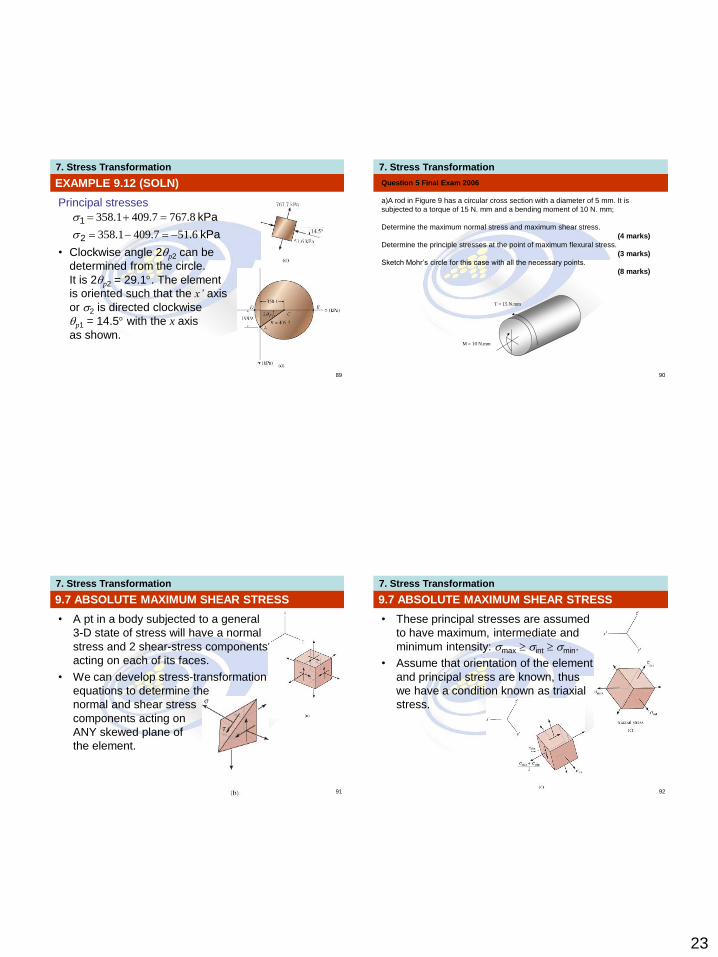
EXAMPLE 9.12 (SOLN)
Principal stresses
• Clockwise angle 2p2 can be
determined from the circle.
It is 2p2 = 29.1. The element
is oriented such that the x’ axis
or 2 is directed clockwise
p1 = 14.5 with the x axis
as shown.
kPa
kPa
2
1
6.517.4091.358
8.7677.4091.358
7. Stress Transformation
90
Question 5 Final Exam 2006
a)A rod in Figure 9 has a circular cross section with a diameter of 5 mm. It is
subjected to a torque of 15 N. mm and a bending moment of 10 N. mm;
Determine the maximum normal stress and maximum shear stress.
(4 marks)
Determine the principle stresses at the point of maximum flexural stress.
(3 marks)
Sketch Mohr’s circle for this case with all the necessary points.
(8 marks)
T = 15 N.mm
M = 10 N.mm
7. Stress Transformation
91
• A pt in a body subjected to a general
3-D state of stress will have a normal
stress and 2 shear-stress components
acting on each of its faces.
• We can develop stress-transformation
equations to determine the
normal and shear stress
components acting on
ANY skewed plane of
the element.
9.7 ABSOLUTE MAXIMUM SHEAR STRESS
7. Stress Transformation
92
• These principal stresses are assumed
to have maximum, intermediate and
minimum intensity: max int min.
• Assume that orientation of the element
and principal stress are known, thus
we have a condition known as triaxial
stress.
9.7 ABSOLUTE MAXIMUM SHEAR STRESS
24
7. Stress Transformation
93
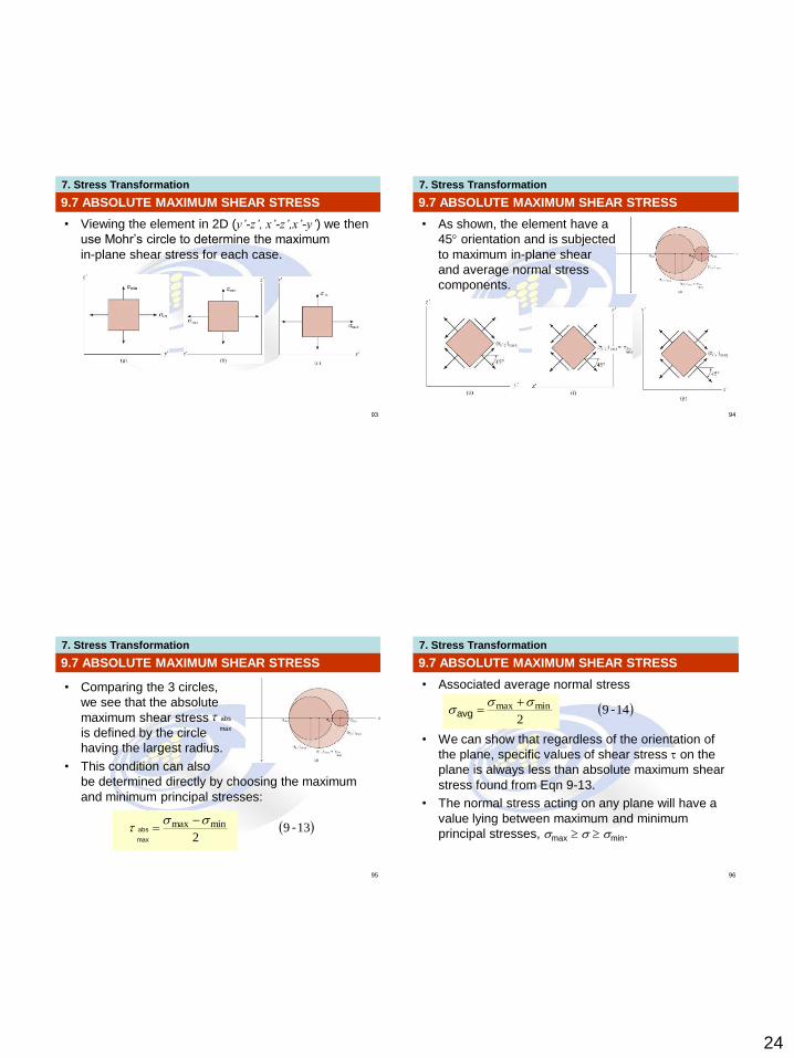
• Viewing the element in 2D (y’-z’, x’-z’,x’-y’) we then
use Mohr’s circle to determine the maximum
in-plane shear stress for each case.
9.7 ABSOLUTE MAXIMUM SHEAR STRESS
7. Stress Transformation
94
• As shown, the element have a
45 orientation and is subjected
to maximum in-plane shear
and average normal stress
components.
9.7 ABSOLUTE MAXIMUM SHEAR STRESS
7. Stress Transformation
95
9.7 ABSOLUTE MAXIMUM SHEAR STRESS
• Comparing the 3 circles,
we see that the absolute
maximum shear stress
is defined by the circle
having the largest radius.
• This condition can also
be determined directly by choosing the maximum
and minimum principal stresses:
max
abs
1392
minmax -max
abs
7. Stress Transformation
96
• Associated average normal stress
• We can show that regardless of the orientation of
the plane, specific values of shear stress on the
plane is always less than absolute maximum shear
stress found from Eqn 9-13.
• The normal stress acting on any plane will have a
value lying between maximum and minimum
principal stresses, max min.
9.7 ABSOLUTE MAXIMUM SHEAR STRESS
1492
minmax -avg

25
7. Stress Transformation
97
Plane stress
• Consider a material subjected to plane
stress such that the in-plane principal
stresses are represented as max and
int, in the x’ and y’ directions respectively;
while the out-of-plane principal stress in the z’
direction is min = 0.
• By Mohr’s circle and Eqn. 9-13,
9.7 ABSOLUTE MAXIMUM SHEAR STRESS
1592max
max'' -maxabs
zx
7. Stress Transformation
98
Plane stress
• If one of the principal stresses has
an opposite sign of the other, then
these stresses are represented as
max and min, and out-of-plane
principal stress int = 0.
• By Mohr’s circle and Eqn. 9-13,
9.7 ABSOLUTE MAXIMUM SHEAR STRESS
1692
minmax
max''
-
maxabs
yx
7. Stress Transformation
99
9.7 ABSOLUTE MAXIMUM SHEAR STRESS
IMPORTANT
• The general 3-D state of stress at a pt can be represented by an element oriented so that only three principal stresses act on it.
• From this orientation, orientation of element representing the absolute maximum shear stress can be obtained by rotating element 45 about the axis defining the direction of int.
• If in-plane principal stresses both have the same sign, the absolute maximum shear stress occurs out of the plane, and has a value of 2max
max
abs
7. Stress Transformation
100
9.7 ABSOLUTE MAXIMUM SHEAR STRESS
IMPORTANT
• If in-plane principal stresses are of opposite signs, the absolute maximum shear stress equals the maximum in-plane shear stress; that is
2minmax max
abs

26
7. Stress Transformation
101
EXAMPLE 9.14
Due to applied loading,
element at the pt on the
frame is subjected to the
state of plane stress shown.
Determine the principal
stresses and absolute
maximum shear stress
at the pt.
7. Stress Transformation
102
EXAMPLE 9.14 (SOLN)
Principal stresses
The in-plane principal stresses can be determined
from Mohr’s circle. Center of circle is on the axis at
avg = (20 + 0)/2 = 10 kPa. Plotting controlling pt
A (20, 40), circle can be drawn as shown. The
radius is
kPa2.41
40102022
R
7. Stress Transformation
103
EXAMPLE 9.14 (SOLN)
Principal stresses
The principal stresses at the pt where the circle
intersects the -axis:
From the circle, counterclockwise angle 2, measured
from the CA to the axis is,
kPa
kPa
2.512.4110
2.312.4110
min
max
0.38
0.761020
40tan2 1
Thus,
7. Stress Transformation
104
EXAMPLE 9.14 (SOLN)
Principal stresses
This counterclockwise rotation defines
the direction of the x’ axis or min and
its associated principal plane. Since
there is no principal stress on the
element in the z direction, we have
kPa
kPa
2.51
0
2.31
min
int
max
27
7. Stress Transformation
105
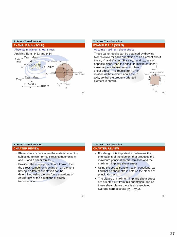
EXAMPLE 9.14 (SOLN)
Absolute maximum shear stress
Applying Eqns. 9-13 and 9-14,
kPa
avg
102
2.512.31
2minmax
kPa
maxabs
2.412
)2.512.31
2minmax
7. Stress Transformation
106
EXAMPLE 9.14 (SOLN)
Absolute maximum shear stress
These same results can be obtained by drawing
Mohr’s circle for each orientation of an element about
the x’, y’, and z’ axes. Since max and min are of
opposite signs, then the absolute maximum shear
stress equals the maximum in-plane
shear stress. This results from a 45
rotation of the element about the z’
axis, so that the properly oriented
element is shown.
7. Stress Transformation
107
CHAPTER REVIEW
• Plane stress occurs when the material at a pt is
subjected to two normal stress components x
and y and a shear stress xy.
• Provided these components are known, then
the stress components acting on an element
having a different orientation can be
determined using the two force equations of
equilibrium or the equations of stress
transformation.
7. Stress Transformation
108
CHAPTER REVIEW
• For design, it is important to determine the
orientations of the element that produces the
maximum principal normal stresses and the
maximum in-plane shear stress.
• Using the stress transformation equations, we
find that no shear stress acts on the planes of
principal stress.
• The planes of maximum in-plane shear stress
are oriented 45 from this orientation, and on
these shear planes there is an associated
average normal stress (x + y)/2.
28
7. Stress Transformation
109
CHAPTER REVIEW
• Mohr’s circle provides a semi-graphical aid for
finding the stress on any plane, the principal normal
stresses, and the maximum in-plane shear stress.
• To draw the circle, the and axes are
established, the center of the circle [(x + y)/2, 0],
and the controlling pt (x, xy) are plotted.
• The radius of the circle extends between these two
points and is determined from trigonometry.
7. Stress Transformation
110
CHAPTER REVIEW
• The absolute maximum shear stress will be
equal to the maximum in-plane shear stress,
provided the in-plane principal stresses have
the opposite sign.
• If they are of the same sign, then the absolute
maximum shear stress will lie out of plane. Its
value is .2/0maxmax
abs
Related Documents

![Plane Stress Tutorial[1]](https://static.cupdf.com/doc/110x72/577ce0481a28ab9e78b2ff18/plane-stress-tutorial1.jpg)