Diagnosis of Winding Faults with Frequency Response Analysis in Power Transformers Conference on Electrical Power Equipment Diagnostics Bali, Indonesia Thomas Prevost

Welcome message from author
This document is posted to help you gain knowledge. Please leave a comment to let me know what you think about it! Share it to your friends and learn new things together.
Transcript

Diagnosis of Winding Faults with Frequency Response Analysis in Power Transformers Conference on Electrical Power Equipment Diagnostics Bali, Indonesia Thomas Prevost
Theory
© OMICRON Page 2
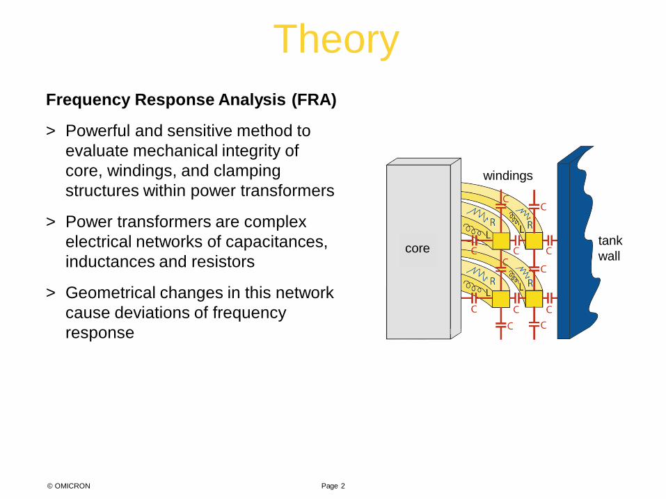
Frequency Response Analysis (FRA)
> Powerful and sensitive method to evaluate mechanical integrity of core, windings, and clamping structures within power transformers
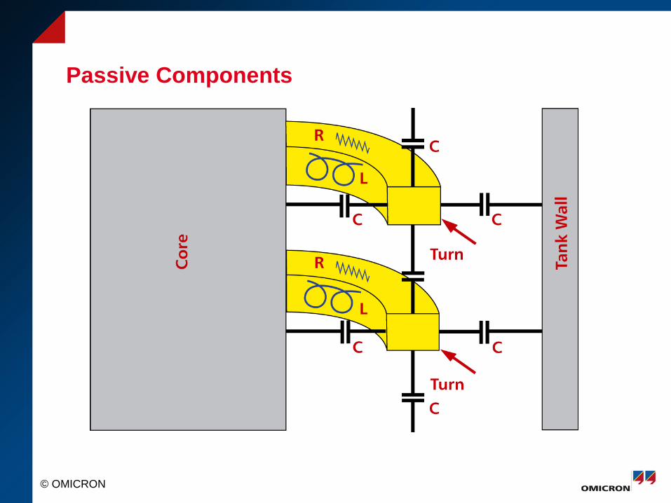
> Power transformers are complex electrical networks of capacitances, inductances and resistors
> Geometrical changes in this network cause deviations of frequency response
tank wall
windings
core

Theory
Page 3 © OMICRON
Frequency Response Analysis (FRA)
> FRAnalyzer performs Sweep Frequency Response Analysis (SFRA) > Measurement of electrical transfer functions over a wide frequency range > Worldwide proven method for measurements in frequency domain > Evaluation of transformer condition by comparing SFRA results to
reference results
> Different failures are directly related to different sections of the frequency range and can usually be discerned from each other
Mag
nitu
de in
dB
Frequency in Hz
0
-20
-40
-60
-80
101 103 105 107
Core influence
Interaction between windings
Winding structure influence
Earthing leads
influence

Theory
© OMICRON Page 4
When to perform a Frequency Response Analysis
> After short-circuit testing
> Before and after transport
> After the occurrence of high transient fault currents
> For diagnostic routine measurements
> After significant changes of monitored values
> After the observation of unusual routine test results

Methods
Page 5 © OMICRON
How FRAnalyzer analyzes frequency response
> Injection of sinusoidal excitation voltage with continuously increasing frequency into one end of the transformer winding
> Measurement of signal returning from the other end
Results Sine generator, variable frequency
Transformer (complex network)
Methods
Page 6 © OMICRON
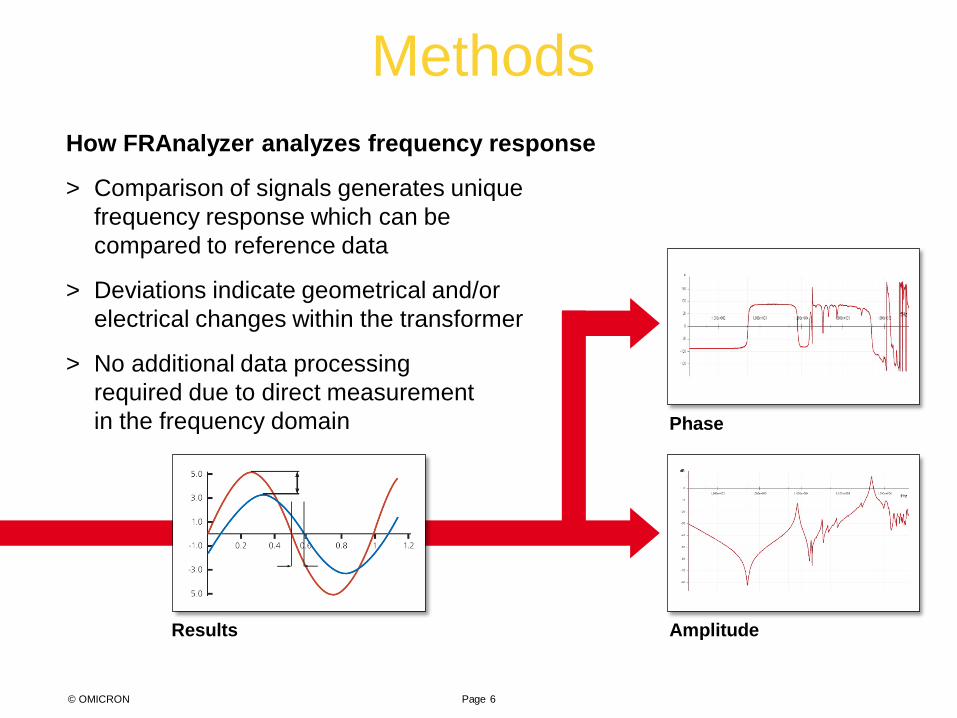
How FRAnalyzer analyzes frequency response
> Comparison of signals generates unique frequency response which can be compared to reference data
> Deviations indicate geometrical and/or electrical changes within the transformer
> No additional data processing required due to direct measurement in the frequency domain
Results
Phase
Amplitude

© OMICRON
What is SFRA?
• Powerful and sensitive tool to assess the mechanical and electrical integrity of power transformers active part
• Measurement of the transfer function over a wide frequency range

© OMICRON
SFRA Discussion Outline
1. Basic SFRA Theory, History, and Evolution 2. SFRA Measurement Characteristics 3. Failure Modes 4. Test Procedures 5. Analysis of Results 6. Case Sudies

© OMICRON
Standardization in the World
CHINA
DL 911/2004 C57.149 WG A2.26
IEC 60076-18

© OMICRON
Life Cycle
Delivery Port
Reception Port
Manufacturer Workshop
•Quality Assuring
•After Short Circuit Test
•Failure Investigation
•Transport Checking
•Transport Checking
•Routine Measurement
•After Transients/Overcurrents
•Failure Investigation (DGA)
Truck Transport 1
Truck Transport 2
Ship Transport
© OMICRON
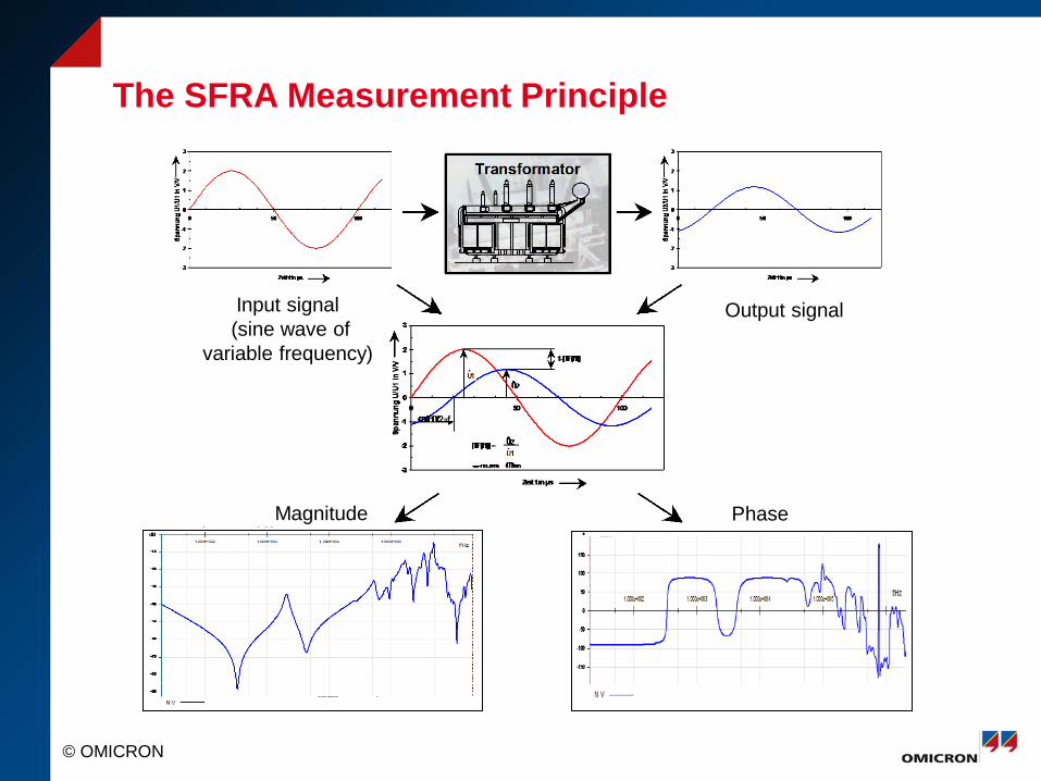
The SFRA Measurement Principle
Input signal (sine wave of
variable frequency)
Output signal
Phase Magnitude

© OMICRON
Theoretical Background
Measurementcable
Measurementcable
CMC
CMC
CMC
CMC
RMC12 RMC34
Complex RLC Network
U1
Cables Grounding
50Ω U2 50Ω
50Ω
)sin()( φω += tYty
tXtx ωsin)( =
)/(log20 1210 UUk =
)/(tan 121 UU ∠∠= −ϕ
Magnitude (k) Phase
specimenm
m
ZRR
sUsUTF
+==
)()(
1
2
Presenter
Presentation Notes
This slide explains the so-called sweep frequency method. In contrast to the impulse method, here we work with a sinusoidal signal, which is swept between 10 Hz and 10/20 kHz (or more). Vin – represented in red – is the input signal, which is standardized to 1 or 100%. We sweep the signal over the whole frequency range and measure the signal Vout - represented in blue - at the other end of the winding. We see that the blue signal (output signal) compared to the red signal (input signal) shows both a damping as well as a phase shift. The transfer function (H) in dB is the result of the calculation according the shown formula: H(dB) = .... Advantages of the sweep FRA method: The input amplifiers of the equipment can be realized with a very small bandwidth; by that it can be avoided that other distortion signals superimpose the measurement signal Over the whole frequency range we have a constant amplitude of the oscillator signal and by that no limitation of / a constant energy at higher frequencies. This allows a more sensitive measurement of particularly at higher resonance frequencies.
© OMICRON
Passive Components

© OMICRON
RLC Characteristics
101
102
103
104
105
106
107
-150
-100
-50
0
Frequency (Hz)
Am
plitu
de [d
B]
101
102
103
104
105
106
107
-100
-50
0
Frequency (Hz)
Pha
se [°
]
L=200 mHL=2 mHL=20 H
L=200 mHL=2 mHL=20 H
101
102
103
104
105
106
107
-200
-150
-100
-50
0
Frequency (Hz)A
mpl
itude
[dB
]
C=1uFC=20nFC=1pF
101
102
103
104
105
106
107
0
50
100
Frequency (Hz)
Pha
se [°
]
C=1uFC=20nFC=1pF

© OMICRON
Failure Mode Identified with SFRA 1. Radial “Hoop Buckling” Deformation of Winding
2. Axial Winding Elongation “Telescoping”
3. Overall- Bulk & Localized Movement
4. Core Defects
5. Contact Resistance
6. Winding Turn-to-Turn Short Circuit
7. Open Circuited Winding
• Residual Magnetization
• Oil Status (With or Without)
• Grounding

© OMICRON
Radial Failure
Presenter
Presentation Notes
This slides shows the standard FRA measuring method: The yellow cable (generator output) is connected to the beginning of the winding, with the red cable the injected voltage is measured back to compensate wiring influences (reference channel). With the blue cable (output) the damped signal at the other end of the same winding is fed back to equipment to the measurement input. This is the standard FRA method which should be applied as a minimum for all FRA measurements. The measurement is performed for each phase: If a transformer has two voltage levels this means that six measurements are performed, if we have a three-winding transformer (upper, medium, and low voltage winding), nine such measurements are necessary.

© OMICRON
Axial Failure
Presenter
Presentation Notes
This slides shows the standard FRA measuring method: The yellow cable (generator output) is connected to the beginning of the winding, with the red cable the injected voltage is measured back to compensate wiring influences (reference channel). With the blue cable (output) the damped signal at the other end of the same winding is fed back to equipment to the measurement input. This is the standard FRA method which should be applied as a minimum for all FRA measurements. The measurement is performed for each phase: If a transformer has two voltage levels this means that six measurements are performed, if we have a three-winding transformer (upper, medium, and low voltage winding), nine such measurements are necessary.

© OMICRON
Conductor Tilting
Presenter
Presentation Notes
This slides shows the standard FRA measuring method: The yellow cable (generator output) is connected to the beginning of the winding, with the red cable the injected voltage is measured back to compensate wiring influences (reference channel). With the blue cable (output) the damped signal at the other end of the same winding is fed back to equipment to the measurement input. This is the standard FRA method which should be applied as a minimum for all FRA measurements. The measurement is performed for each phase: If a transformer has two voltage levels this means that six measurements are performed, if we have a three-winding transformer (upper, medium, and low voltage winding), nine such measurements are necessary.

© OMICRON
Core Failure Modes
• Over-Heating
• Bulk Movement
• Multiple Core Grounding
• Lamination Gaps
• Shorted Laminations
• Ungrounded Core

© OMICRON
Typical Results
f/Hz5.000e+001 1.000e+002 5.000e+002 1.000e+003 5.000e+003 1.000e+004 5.000e+004 1.000e+005 5.000e+005 1.000e+006
dB
-70
-60
-50
-40
-30
-20
N W sec N V sec N U
f/Hz5.000e+001 1.000e+002 5.000e+002 1.000e+003 5.000e+003 1.000e+004 5.000e+004 1.000e+005 5.000e+005 1.000e+006
°
-100
-50
100
150
© OMICRON
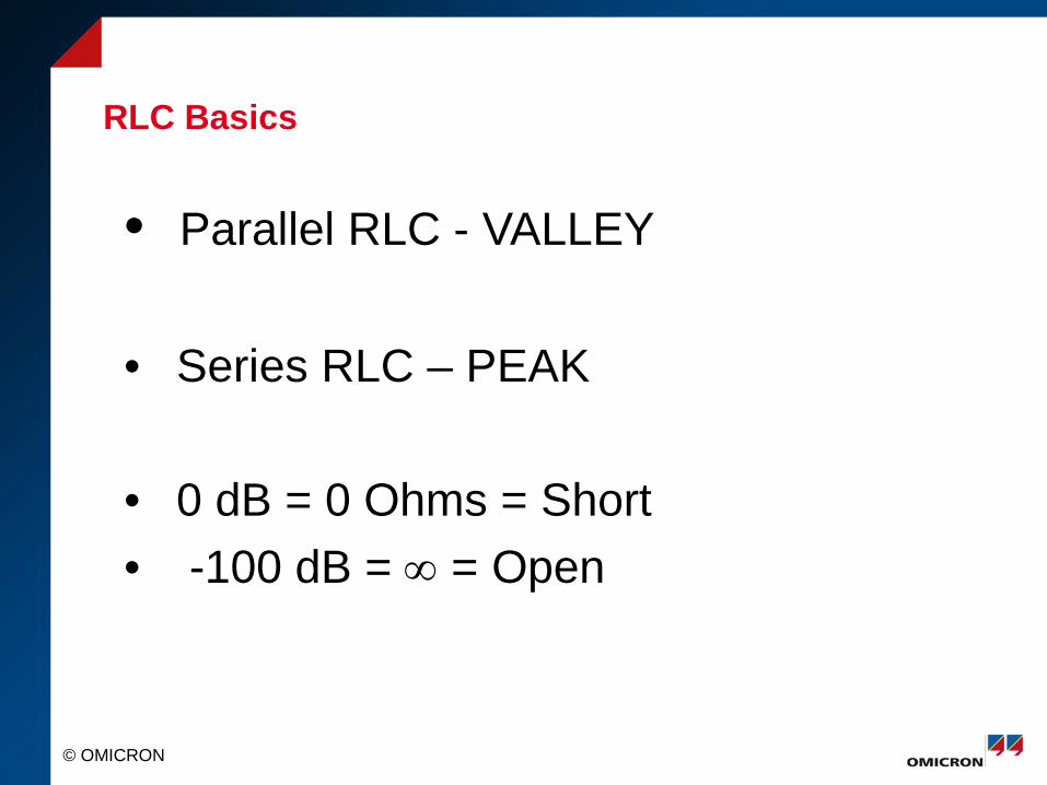
RLC Basics
• Parallel RLC - VALLEY
• Series RLC – PEAK
• 0 dB = 0 Ohms = Short • -100 dB = ∞ = Open

© OMICRON
Typical Results f/Hz
5.000e+001 1.000e+002 5.000e+002 1.000e+003 5.000e+003 1.000e+004 5.000e+004 1.000e+005 5.000e+005 1.000e+006
dB
-70
-60
-50
-40
-30
-20
N W sec N V sec N U
f/Hz5.000e+001 1.000e+002 5.000e+002 1.000e+003 5.000e+003 1.000e+004 5.000e+004 1.000e+005 5.000e+005 1.000e+006
°
-100
-50
100
150

© OMICRON
Measurement Setup – OPEN CIRCUIT
Presenter
Presentation Notes
This slides shows the standard FRA measuring method: The yellow cable (generator output) is connected to the beginning of the winding, with the red cable the injected voltage is measured back to compensate wiring influences (reference channel). With the blue cable (output) the damped signal at the other end of the same winding is fed back to equipment to the measurement input. This is the standard FRA method which should be applied as a minimum for all FRA measurements. The measurement is performed for each phase: If a transformer has two voltage levels this means that six measurements are performed, if we have a three-winding transformer (upper, medium, and low voltage winding), nine such measurements are necessary.

© OMICRON
HV vs. LV Winding Responses
Presenter
Presentation Notes
FRAnalyzer is completely PC controlled comprising a convenient, versatile software. This slide shows the screen which appears after the FRAnalyzer software has been started up. The upper part contains a list of all transformers where measurements so far have been made. The lower part contains a corresponding list of all measurements available for the transformer currently selected in the upper list.

© OMICRON
Open Circuit Tests

© OMICRON
Measurement Setup – SHORT CIRCUIT
Short Circuit Test
Presenter
Presentation Notes
This slides shows the standard FRA measuring method: The yellow cable (generator output) is connected to the beginning of the winding, with the red cable the injected voltage is measured back to compensate wiring influences (reference channel). With the blue cable (output) the damped signal at the other end of the same winding is fed back to equipment to the measurement input. This is the standard FRA method which should be applied as a minimum for all FRA measurements. The measurement is performed for each phase: If a transformer has two voltage levels this means that six measurements are performed, if we have a three-winding transformer (upper, medium, and low voltage winding), nine such measurements are necessary.

© OMICRON
Open vs. Shorted tests

© OMICRON
Short Circuit Tests
© OMICRON
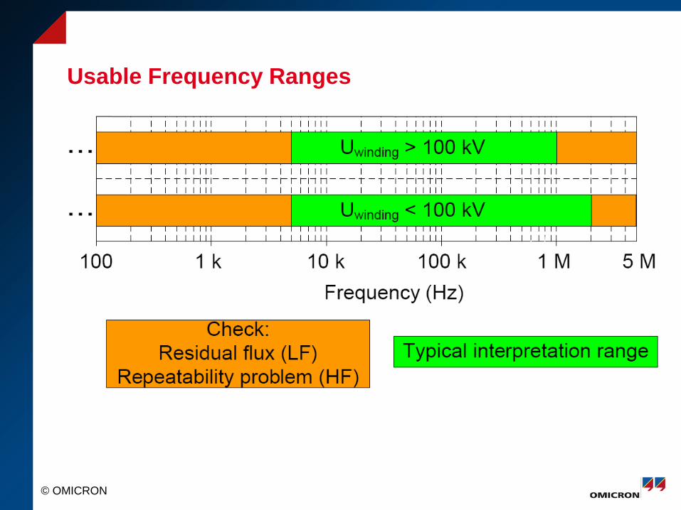
Usable Frequency Ranges

© OMICRON
Transformer Types
• 2 Winding (H, X) 3-H OC 3-X OC 3-HX SC
• 3 Winding (H, X, Y) 3-H OC 3-X OC 3-Y OC 3-HX SC 3-HY SC
• Auto Transformer (Series, Common, Tert) 3-H Series OC 3-X Common OC 3-Y Tert OC 3-HX SC 3-HY SC

© OMICRON
Test Connections

© OMICRON
Test Recommendations (IEEE)
• LTC Extreme Raise
• DETC as Found
• Open Circuit Test
• Short Circuit Test

© OMICRON
Series Winding Open Circuit Test
H1-X1 (A) H2-X2 (B) H3-X3(C)

© OMICRON
Common Winding Open Circuit Test
X1-X0 (A) X2-X0 (B) X3-X0 (C)
© OMICRON
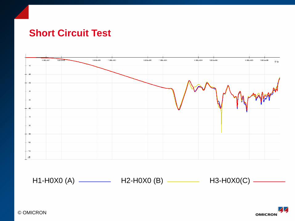
Short Circuit Test
H1-H0X0 (A) H2-H0X0 (B) H3-H0X0(C)

© OMICRON
Overview of B Phase
H1-X2 (B) X2-X0 (B) H2-H0X0 (B)

© OMICRON
Analysis Strategies
1. Baseline 2. Similar Unit
3. Phase Comparison

© OMICRON
SFRA Interpretation
Fingerprint
Date X Date Y
Tim
e ba
sed
com
paris
on
Pha
se b
ased
com
paris
on
f/Hz1.000e+002 5.000e+002 1.000e+003 5.000e+003 1.000e+004 5.000e+004 1.000e+005 5.000e+005 1.000e+006
dB
-80
-70
-60
-50
-40
-30
-20
-10
f/Hz1.000e+002 5.000e+002 1.000e+003 5.000e+003 1.000e+004 5.000e+004 1.000e+005 5.000e+005 1.000e+006
dB
-80
-70
-60
-50
-40
-30
-20
-10
f/Hz1.000e+002 5.000e+002 1.000e+003 5.000e+003 1.000e+004 5.000e+004 1.000e+005 5.000e+005 1.000e+006
dB
-80
-70
-60
-50
-40
-30
-20
-10
A B C A B C
f/Hz1.000e+002 5.000e+002 1.000e+003 5.000e+003 1.000e+004 5.000e+004 1.000e+005 5.000e+005 1.000e+006
dB
-80
-70
-60
-50
-40
-30
-20
-10
A vs B vs C
A B C A B C
f/Hz1.000e+002 5.000e+002 1.000e+003 5.000e+003 1.000e+004 5.000e+004 1.000e+005 5.000e+005 1.000e+006
dB
-80
-70
-60
-50
-40
-30
-20
-10
f/Hz1.000e+002 5.000e+002 1.000e+003 5.000e+003 1.000e+004 5.000e+004 1.000e+005 5.000e+005 1.000e+006
dB
-80
-70
-60
-50
-40
-30
-20
-10
Construction based comparison
© OMICRON
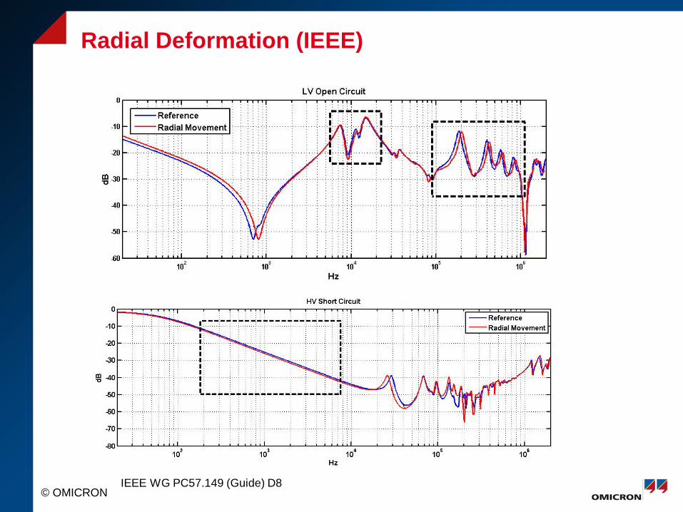
Radial Deformation (IEEE)
IEEE WG PC57.149 (Guide) D8
© OMICRON
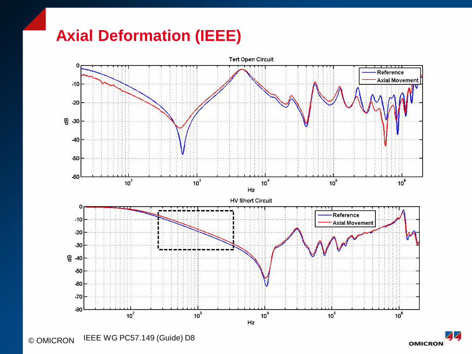
Axial Deformation (IEEE)
IEEE WG PC57.149 (Guide) D8
© OMICRON
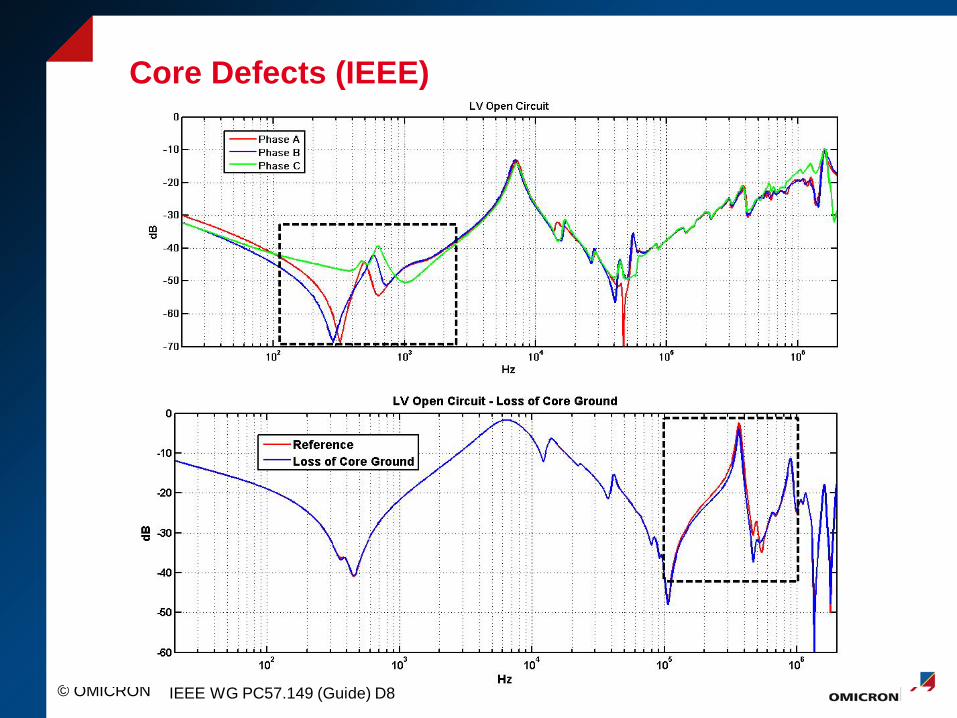
Core Defects (IEEE)
IEEE WG PC57.149 (Guide) D8

© OMICRON
1969 Transformer
CASE STUDY

Initial Problem
Phase 1: Trip out of Service, Differential
Phase 2: DGA

Initial Problem
Phase 1: Trip out of Service, Differential
Phase 2: DGA
Phase 3: Test -Visual Inspection -Power Factor -Exciting Current -Transformer Turns Ratio -SFRA -Second DGA – 19 PPM of Acetylne

Phase 4: Reviewed SFRA data

HV Open Circut

LV Open Circut
© OMICRON
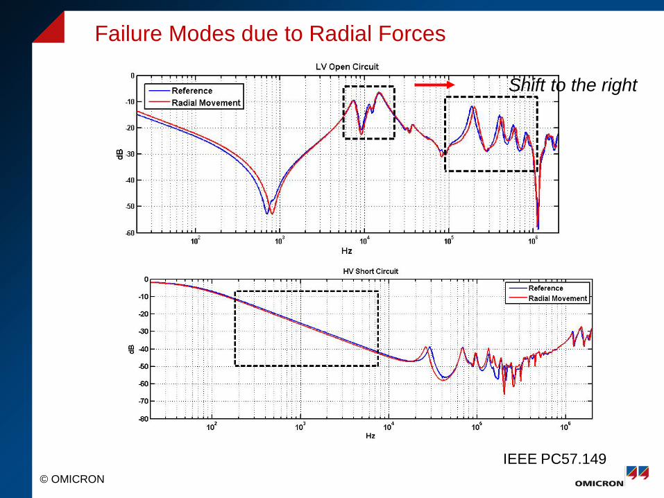
Failure Modes due to Radial Forces
IEEE PC57.149
Shift to the right

HV Short Circut

HV Short Circut – Zoom In
~0.1db difference.. Not bad!

Phase 4: Reviewed SFRA data
Phase 6: Perform Addition Test -Leakage Reactance +FRSL -Winding Resistance

Leakage Reactance – 3 Phase Equivalent and Per Phase Test
9.62% difference compared to average!

Leakage Reactance – FRSL

Winding Resistance

Phase 4: Reviewed SFRA data
Phase 5: Perform Addition Test -Leakage Reactance +FRSL -Winding Resistance
Phase 6: Tear down
During Tear Down, Transformer caught on fire

Tear Down
B Phase
Take a closer look
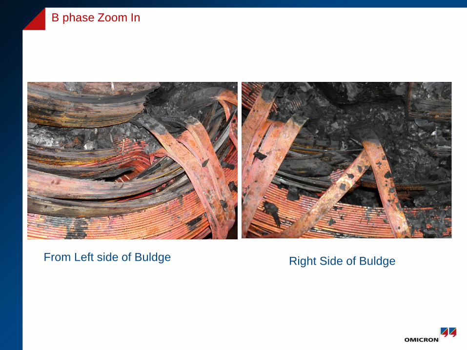
From Left side of Buldge
B phase Zoom In
Right Side of Buldge

© OMICRON
Fault on a furnace 25 MVA transformer

© OMICRON
Overpressure valve was spitting out 200l of oil
© OMICRON
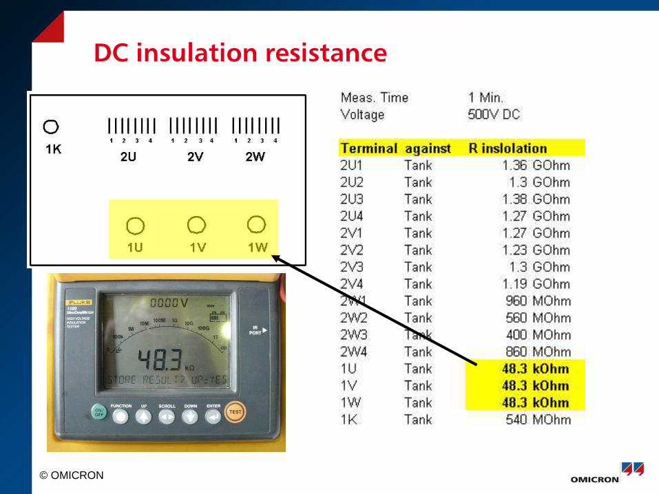
DC insulation resistance

© OMICRON
Ratio error [%]
Ratio Deviation (Tap)
-0.9-0.8-0.7-0.6-0.5-0.4-0.3-0.2-0.1
00.1
000 005 010 015 020Taps
UVW

© OMICRON
No-Load Current
Excitation Current
0
0.1
0.2
0.3
0.4
0.5
0.6
0.7
000 005 010 015 020Taps
Io UIo VIo W
Angle of Excitation Current
-60.0°
-50.0°
-40.0°
-30.0°
-20.0°
-10.0°
0.0°
000 005 010 015 020Taps
Phase (I) UPhase (I) VPhase (I) W
Taps
Taps

© OMICRON
Z0 (f) = R0 (f) + j X0 (f)
0.0Ω
1000.0Ω
2000.0Ω
3000.0Ω
4000.0Ω
5000.0Ω
6000.0Ω
0.0Hz 100.0Hz 200.0Hz 300.0Hz 400.0Hz 500.0Hz
R0 W17R0 V17R0 U17
0.0Ω
1000.0Ω
2000.0Ω
3000.0Ω
4000.0Ω
5000.0Ω
6000.0Ω
0.0Hz 100.0Hz 200.0Hz 300.0Hz 400.0Hz 500.0Hz
X0 W17X0 V17X0 U17
© OMICRON
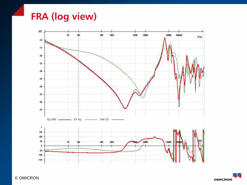
FRA (log view)

© OMICRON
Comparison to known cases
Tested transformer
Faulty B phase
Transformer with shorted tertiary winding

© OMICRON
FRA (linear view)
Faulty B phase
Faulty B phase
© OMICRON
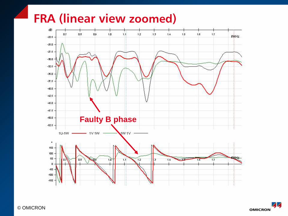
FRA (linear view zoomed)
Faulty B phase

© OMICRON
Opened transformer

© OMICRON
Opened transformer

© OMICRON
Melted screw

© OMICRON
Melted screw
© OMICRON
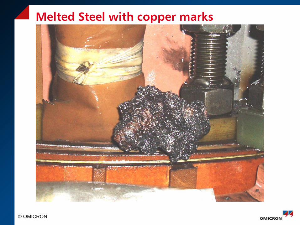
Melted Steel with copper marks

© OMICRON
Interrupted screen connection

© OMICRON
Interrupted screen connection
© OMICRON
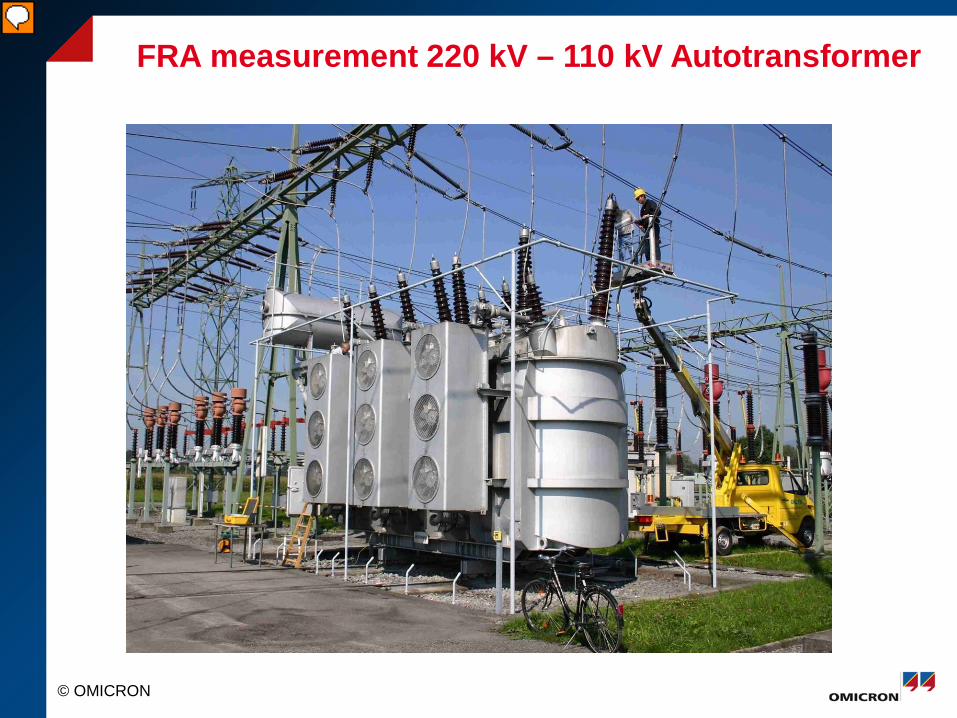
FRA measurement 220 kV – 110 kV Autotransformer
Presenter
Presentation Notes
This slide shows a practical measurement at a 220 kV transformer. In the area of the manlift –allowing an easy connection to the high voltage winding – we see the 220 kV bushing; in the front – towards the yellow transport case / measuring equipment – we see the 110 kV bushings. Not visible in this picture are the tertiary terminals, in this case for the 10 kV windings.

© OMICRON
Measurement (2)
Presenter
Presentation Notes
This picture shows the measuring arrangement in front of the transformer.

© OMICRON
Results 110 kV
Presenter
Presentation Notes
This picture shows a comparison of the FRA measurement results of the three 110 kV phases.

© OMICRON
Results 220 kV
Presenter
Presentation Notes
This picture shows the equivalent results on the 220 kV side.

© OMICRON
Chinese standard DL/T 911-2004
Standard variance of two compared sequences 21
0
1
0)(
N1-)(1 ∑ ∑
−
=
−
=
=
N
K
N
Kx kXkX
ND
21
0
1
0)(
N1-)(1 ∑ ∑
−
=
−
=
=
N
K
N
Ky kYkY
ND
Covariance of two compared sequences 21N
0K
1N
0Kxy X(k)
N1-X(k)
N1C ∑ ∑
−
=
−
=
= ×
21
0)(
N1-)(
∑−
=
N
KkYkY
Normalized covariance factor LRxy=Cxy / yx DD
Relative factor Rxy =
−−<− −
othersLRgLR
XY
xy
)1(110110 10
Presenter
Presentation Notes
This picture shows the equivalent results on the 220 kV side.

© OMICRON
Chinese standard DL/T 911-2004
Winding Deformation degree Relative Factors R
Severe Deformation RLF < 0.6
Obvious Deformation 1.0> RLF ≥ 0.6 or RMF < 0.6
Slight Deformation 2.0> RLF ≥ 1.0 or 0.6 ≤ RMF < 1.0
Normal Winding RLF ≥ 2.0, RMF ≥ 1.0 and RHF ≥ 0.6
RLF in the range 1kHz∼100kHz RMF in the range 100kHz∼600kHz RHF in the range 600kHz∼1000kHz
Presenter
Presentation Notes
This picture shows the equivalent results on the 220 kV side.

© OMICRON
Good winding according to DL/T 911-2004
Presenter
Presentation Notes
This picture shows the equivalent results on the 220 kV side.

© OMICRON
Defective winding according to DL/T 911-2004
Presenter
Presentation Notes
This picture shows the equivalent results on the 220 kV side.

Thank You for Your Attention
Related Documents