CHAPTER VII Radio Aspects, Cell Sites and Antenna Subsystem by Miftadi Sudjai, Ir., MSc., MPhil Lab. Antena Jurusan Teknik Elektro STTTELKOM

7-Cp VII Antena & Cell Site
Nov 29, 2015
antena dan sel
Welcome message from author
This document is posted to help you gain knowledge. Please leave a comment to let me know what you think about it! Share it to your friends and learn new things together.
Transcript

CHAPTER VII
Radio Aspects, Cell Sites and
Antenna Subsystem
by
Miftadi Sudjai, Ir., MSc., MPhilLab. Antena
Jurusan Teknik Elektro
STTTELKOM

Cellular Radio Access System
MSC
PSTN
Packet/IPNetwork
BTS1/cell site 1
BTS1/cell site n

Radio (Tx & Rx) System
• Signal Source: Informasi & Baseband Processing.• Tx-er: Modulator, Channel Encoder, Interleaver, etc.• PA: Power Amplifier.• Feedline: Cable, Connector and Jumper.• Pre-Amp: LNA.• Rx-er: Demodulator, Channel Decoder, De-Interleaver, etc.
RxerPASignalInformation
Txer
SignalSource(Voice, data, etc)
propagation
feedlineTx filter Rx filter Pre-Amp

Structure of Transmitter
• BB Processing: to process analog signal into digital signal & other processing• Mod: translate from BB freq. To RF freq depend on type of cellular system being
used e.g. G-MSK modulator for GSM.• Power Amp:
- Class A: high linearity- Class B: greater output power more efficient than Class A, but less linear- Class AB: combined adv. of class A & B become widely used in wireless.- Class C: more power efficient widely used in wireless
BBProcessing
Mod PAInfoSignal
Jumper
Jumper
Cable
Connector
Depend ontype of Mod used

Generic Structure of Rxer
• Block diagram of Rxer varies depend on type of modulation, encoder, and/ or base band processing.
• Parameters to be considered are:- frequency range- dynamic range- sensitivity- distortion- noise- tuning speed
12...
N
ChanelEncoder
PAData/Signal
filter
jumper
Multicoupler/RF Distributor
X IF
LOfeedline
Antenna
IF
Rxer

• Antenna: to convert electromagnetic energy from atmosfer electric energy and transfer it to feed line
• Feed line
Receiver Components
Jumper Cable Jumper
• Filter & Pre-Amplifier:- Filter: to pass the wanted signal & attenuated the interference designed to work according to the intended bands- Pre-Amplifier is used to increased S/N of received signals.
= Connector
Jumper to ease maintenance and installation
Receiver Components
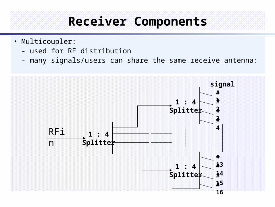
• Multicoupler:- used for RF distribution- many signals/users can share the same receive antenna:
1 : 4Splitter
1 : 4Splitter
# 1
# 2
# 3
# 4
1 : 4Splitter
# 13
# 14
# 15
# 16
RFin
signal
Performance Criteria of Receivers
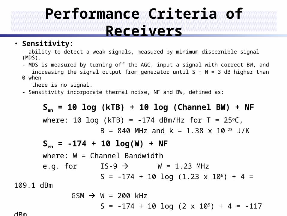
• Sensitivity:- ability to detect a weak signals, measured by minimum discernible signal (MDS).- MDS is measured by turning off the AGC, input a signal with correct BW, and increasing the signal output from generator until S + N = 3 dB higher than 0 when there is no signal.- Sensitivity incorporate thermal noise, NF and BW, defined as:
Sen = 10 log (kTB) + 10 log (Channel BW) + NF
where: 10 log (kTB) = -174 dBm/Hz for T = 25oC,
B = 840 MHz and k = 1.38 x 10⁻²³ J/K
Sen = -174 + 10 log(W) + NF
where: W = Channel Bandwidth
e.g. for IS-9 W = 1.23 MHz
S = -174 + 10 log (1.23 x 10⁶) + 4 = 109.1 dBm
GSM W = 200 kHz
S = -174 + 10 log (2 x 10⁵) + 4 = -117 dBm

Performance Criteria of Receiver• Dynamic Range
- a range of levels of the signal that receiver can handle accurately.- blocking DR is defined from MDS to 1 dB compression point.- spurious free DR (SFDR) is defined from MDS to a specified 3rd order
intermodulation level.
Linear operation
Signal slope
Spurious free dynamic range
Third order
Intercept point
Noise level
Input power, dBm
Input powercausing burnout
Out
put p
ower
, dB
m
1-dB compression
- e.g. a range from -13 to -104 dBm DR = 91 dB

Performance Criteria of Receiver• SINAD = signal to noise and distortion:
dBDN
DNSSINAD
• Noise = thermal noise + other noises:
affect overall performance of receiver
quantified by Noise Figure, NF:
• Selectivity:
- a measure of protection from off channel interference.
- depend upon filtering.
- greater selectivity means better rejection to unwanted signal however if too selective, the signal could be distorted.
NS
NS
NF
output
inputlog10

4 Basic Antenna System
G=2.14 dBi
a. Dipole
G=4 dBi
b. monopole
Ground plane
c. Loop
Ground plane
conductorFeed point
d. Microstrip/ patch
dielectric

Base Station Antenna• Use antenna with higher gain• Could be omnidirectional or sectoral depending on cell type• Collinear antenna:
S
2
2
4
feeder
line
OmnidirectionalRadiationPattern
boresight
main lobe
side lobe(elevation)

• Log periodic dipole array (LPDA)
Base Station Antenna
DipolesTransmissionline
- BW is smaller than LPDA- typical gain 12 – 14 dB
Reflector Driven element (dipole)Directors
• Yagi antenna
Directional RadiationPattern
main lobe
main lobeside lobeback lobe
- very wide BW, with constant SWR- typical gain 10 dBi

SWR of Antenna
• SWR = Vmax/Vmin, define the matching level between antenna and feeder line
• Reflection coefficient:
1
1
SWR
SWR2
2log10Re Lossturn
where represent a percent of reflected power defined by:
SWR of Antenna
Amplitude
Vmax
Vmin
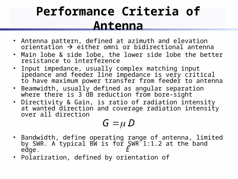
Performance Criteria of Antenna
• Antenna pattern, defined at azimuth and elevation orientation either omni or bidirectional antenna
• Main lobe & side lobe, the lower side lobe the better resistance to interference
• Input impedance, usually complex matching input ipedance and feeder line impedance is very critical to have maximum power transfer from feeder to antenna
• Beamwidth, usually defined as angular separation where there is 3 dB reduction from bore-sight
• Directivity & Gain, is ratio of radiation intensity at wanted direction and coverage radiation intensity over all direction
• Bandwidth, define operating range of antenna, limited by SWR. A typical BW is for SWR 1:1.2 at the band edge.
• Polarization, defined by orientation of E
DG .

Performance Criteria of Antenna• Front to Back Ratio, is ratio between main lobe & back lobe,
very impotant for directional antenna.
• Spatial diversity:
Rx2 Rx1
h
d
)(835
11feet
fx
hd
where f is in MHz

Antenna Installation
a) Tower
Tx
Rx1Rx2
d
b) Roof Top, Edge of Buildingc) Roof Top
d
Rx1
Rx2Tx
d
Rx1
Rx2Tx
d) Wall Mounting
sector 1 Rx1
Rx2
Tx2
3
d

Antenna Installation Tolerance
• Apply to physical oriented & plumbness of its installation
• For omnidirectional antenna, it is unnecessary. But for directi-onal antenna it is very critical
• Usually taken +/- 5% from antenna horizontal/azimuth pattern.
Azimuth/Horizontal Pattern Tolerance from Bore Sight
110O +/- 5.5o
92O +/- 4.5o
60O +/- 3.0o
40O +/- 2.0o
Table: Horizontal Antenna Tolerance

Antenna Isolation
a. vertical
y
Tx
Rx
ywhere
dBy
VI log4028
c. slant
y
angleslantwhere
dBHIHIVISIo
90
Tx Rx
x
b) horizontal
10
log2022
xwhere
dBx
HI

Link Budget
TXer RXer
Txercomponent
Rxercomponent
link budget component
path loss

Link Budget – Up Link
• Frequency range, MHz
• Mobile parameters- Tx PA output (max)- Cable loss- Antenna gain-------- (Subsc. ERP max, dB)
• Environmental margins- Fading margin- Environmental attenuation- Cell overlap
-------------------- (dB)
• Base station parameters
- Rx ant. gain Rx jumper loss
- Rx tower top amp gain (net)
- Rx cable loss
- Rx ligthning arrester loss
- Rx duplexer loss
- Rx diversity gain
- Rx coding gain
- Rx sensitivity
------- Up-link budget, dB

Link Budget – Down Link• Frequency range, MHz
• Base station parameters
- Tx PA output power
- Tx combiner loss
- Tx duplexer loss
- Tx ligthning arrester loss
- Tx cable loss
- Tx jumper loss
- Tx tower top amp gain
- Tx antenna gain
(Cell ERP, dB)
• Environmental margins- Tx diversity gain- Fading margin- Environmental attenuation- Cell overlap
(dB)• Mobile parameters
- Antenna gain - Rx diversity gain- Antenna cable loss- Coding gain- Rx sensitivity
---------- Down-link budget, dB
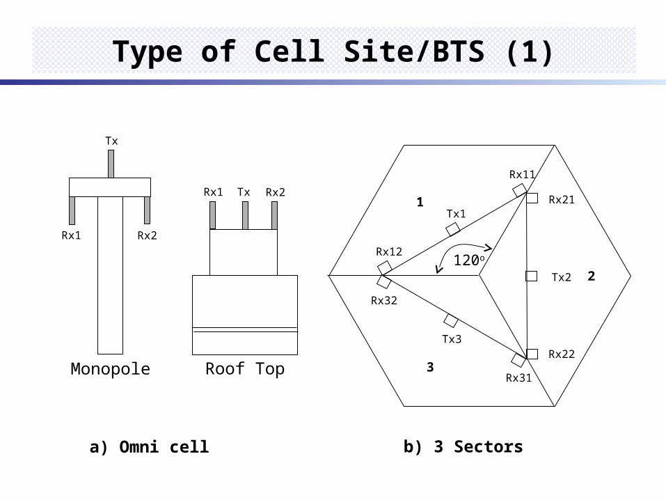
Type of Cell Site/BTS (1)
Monopole
Rx2Rx1
Tx
Roof Top
Rx2Rx1 Tx
a) Omni cell b) 3 Sectors
Rx12
Tx1
Rx11
Rx21
Tx2
Rx22
Rx32
Tx3
Rx31
1
2
3
120o

Type of Cell Site/BTS (2)
c) 6 sectors
T
R
R
R
RR
R
RR R
R
R
R
T
T
T
T
T
1
2
3
4
5
6
d) Microcell or picocell
Traffic light
Micro- or pico-cell antenna
60

Cell Site Design (1)
Site Qualification Test(SQT)
Planning andZoning Board
SiteAccepted?
EMF Compliance
Site activation
Search area
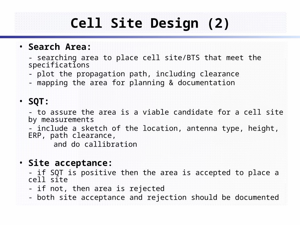
Cell Site Design (2)
• Search Area:- searching area to place cell site/BTS that meet the specifications- plot the propagation path, including clearance- mapping the area for planning & documentation
• SQT:- to assure the area is a viable candidate for a cell site by measurements- include a sketch of the location, antenna type, height, ERP, path clearance,
and do callibration
• Site acceptance:- if SQT is positive then the area is accepted to place a cell site- if not, then area is rejected- both site acceptance and rejection should be documented

Cell Site Design (3)
• Planning and zoning board:- why the site is needed- how the site will improve the network- drawing the sketch of site
• Electromagnetic Force (EMF) Compliance:- EMF identify the source of EM from the site itself and surrounding area- to ensure it complies with personal safety and government regulation- incorporated the type of Txer, power, frequency range, etc- method for calculating EMF, e.g. IEEE C95.1 – 1991 standard
• Site activation:- when every steps above is OK, the cell site/BTS could be placed and turn on

Conclusion
• ..........
• ..........
• ..........
• ..........
• .........
The End
Related Documents


![· Web view– ceturtdaļviļņa vertikālā antena [“ground plane” tipa antena], – antena ar parazītelementiem [jagi],](https://static.cupdf.com/doc/110x72/5aae6cbd7f8b9adb688c5507/view-ceturtdalvilna-vertikala-antena-ground-plane-tipa-antena-.jpg)
