CHAPTER 20 SPRINGS SYMBOLS b ! C C1, C2 C1, C2 dl, d2 D D1 D2 esz ! esr E F F max ko cr g G h area of loading, m 2 (in 2) width of rectangular spring, m (in) width of laminated spring, m (in) width of each strip in a laminated spring, m (in) spring index constants taken from Table 20-1 and to be used in Eqs. (20-1) to (20-36) constants to be used in Eqs. (20-20) and (20-21) and taken from Fig. 20-3 diameter of spring wire, m (in) diameter of torsion bar, m (in) diameter of outer and inner wires of concentric spring, m (in) mean or pitch diameter of spring, m (mm) overall diameter of the absorber, m (in) mean or pitch diameter of outer concentric spring, m (in) smallest mean diameter of conical spring, m (in) mean or pitch diameter of inner concentric spring, m (in) largest mean diameter of conical spring, m (in) size coefficient surface influence coefficient modulus of elasticity, GPa (psi) frequency, cycles per minute, Hz load, kN (lbf) steady-state load [Eq. (20-84)] maximum force that can be imposed on the housing, kN (lbf) force to compress the spring one meter (in) N/m (lbf/in) [spring rate, N/m (lbf/in)] critical load, kN (lbf) acceleration due to gravity, 9.8066 m/s 2 2 2 9806.06 mm/s (32.2 ft/s ; 386.4in/s 2) modulus of rigidity, GPa (psi) height (thickness) of laminated spring, m (in) axial height of a rectangular spring wire, m (in) total number of strips or leaves in a leaf spring number of coils in a helical spring total number of full-length blunt-ended leaves in a leaf spring 20.1

Welcome message from author
This document is posted to help you gain knowledge. Please leave a comment to let me know what you think about it! Share it to your friends and learn new things together.
Transcript

CHAPTER
20 SPRINGS
S Y M B O L S
b !
C
C1, C2
C1, C2
dl, d2 D
D1
D2
esz ! esr
E F F
max
ko
cr g
G h
area of loading, m 2 (in 2) width of rectangular spring, m (in) width of laminated spring, m (in) width of each strip in a laminated spring, m (in) spring index constants taken from Table 20-1 and to be used in Eqs. (20-1) to
(20-36) constants to be used in Eqs. (20-20) and (20-21) and taken from
Fig. 20-3 diameter of spring wire, m (in) diameter of torsion bar, m (in) diameter of outer and inner wires of concentric spring, m (in) mean or pitch diameter of spring, m (mm) overall diameter of
the absorber, m (in) mean or pitch diameter of outer concentric spring, m (in) smallest mean diameter of conical spring, m (in) mean or pitch diameter of inner concentric spring, m (in) largest mean diameter of conical spring, m (in) size coefficient surface influence coefficient modulus of elasticity, GPa (psi) frequency, cycles per minute, Hz load, kN (lbf) steady-state load [Eq. (20-84)] maximum force that can be imposed on the housing, kN (lbf) force to compress the spring one meter (in) N/m (lbf/in) [spring rate, N/m (lbf/in)] critical load, kN (lbf) acceleration due to gravity, 9.8066 m/s 2
2 2 9806.06 mm/s (32.2 ft/s ; 386.4in/s 2) modulus of rigidity, GPa (psi) height (thickness) of laminated spring, m (in) axial height of a
rectangular spring wire, m (in) total number of strips or leaves in a leaf spring number of coils
in a helical spring total number of full-length blunt-ended leaves in a leaf spring
20.1
20.2 CHAPTER TWENTY
I k, kl, k2 k4 KI
k r
l lf or lo L
M Mt n
gl a
U
V 7 W
Y Ycr
Z Zo o
7"
C~, O/
0 lJ
moment of inertia, area, m 4, cm 4 (in 4) stress factor (Wahl factor) correction factor factor depends on the ratio lo/D as shown in Fig. 20-8 reduced stress correction factor or Wahl stress factor or fatigue
stress correction factor shear stress correction factor length, m (in) free length of helical spring, m (in) irrD length of the coil part of torsion spring, m (in) effective length of bushing, m (in) overall length of the absorber (Fig. 20-15), m (in) constant depends on do/di as indicated in Fig. 20-3 twisting moment, N m (lbf in) factor of safety actual factor of safety or reliability factor resilience, N m (lbf in) energy to be absorbed by a rubber spring, N m (lbf in) volume of spring, m 3, mm 3 (in 3) specific weight of the spring material, N/m 3 (lbf/in 3) weight of spring, kN (lbf) weight of effective number of coils i involved in the operation of
the spring [Eq. (20-77)], kN (lbf) deflection, m (in) critical deflection, m (in) section modulus, m 3, cm 3 (in 3)
3 3 3 polar section modulus, m , cm ( in ) stress, normal, MPa (psi) shear stress, MPa (psi) constant from Table 20-3 constants from Table 20-3 angular deflection, rad Poisson's ratio
SUFFIXES
1 outside 2 inside a amplitude m mean max maximum min minimum f endurance lirnit (also used for reversed cycle) o endurance limit for repeated cycle
Particular Formula
LEAF SPRINGS (Table 20-1) 1'2'3
The general equation for the maximum stress in springs O" - - -
clFl bh 2
(20-1)

SPRINGS 20 .3
Particular Formula
The general equat ion for the m a x i m u m deflection springs
The thickness of spring
Fo r sizes and tolerances for leaf springs for m o t o r vehicle suspension [4]
c2F[ 3
y = E b h 3
h = c20"[2
ClyE
Refer to Table 20-1 for values of C l and c2.
Refer to Tables 20-2 to 20-5.
(20-2)
(20-3)
T A B L E 20-1 Deflection formula for beams of rectangular cross section and constants in beam Eqs. (20-1) to (20-3)
Maximum Cl, for the c2, for the Particular deflection, Ymax stress deflection
Unit resilience, Nm[m 3 (kgf mm]mm 3)
~F fh
RI+ • IR2 I * - - - - 21 -'
I ' i Constant breadth and depth
+F 1123, b R1 ~ R2 Constant breadth, varying depth
R,~ 2, ~h ~R2 Constant depth, varying breadth
3 2 +2 Ymax -- ~ ~ h ) 18E
4 1,3 3 4 +2 Ymax -- ~ ~ h ) 6E
3 F ( ~ ) 3 Ymax =
~, r h ~ F 4 F ( 1 ) 3 + Ymax = ~
• = I q I
Constant depth and breadth
: ~ F ~ L - b Ymax = ~--~
~t-"==~. b * h 2 Constant breadth, varying depth
• - - I ~h]F-- Constant depth, varying breadth
6 4
6 8
0 .2
6E
o -2
18E
0 .2
6E
6F/" 1"~ 3 6 6 0 -2
Ymax = b--E ~ ) h 6E
Source: K. Lingaiah and B. R. Narayana Iyengar, Machine Design Data Handbook, Engineering College Cooperative Society, Bangalore, India, 1962; K. Lingaiah and B. R. Narayana Iyengar, Machine Design Data Handbook, Vol. I, Suma Publishers, Bangalore, India, 1986; and K. Lingaiah, Machine Design Data Handbook, Vol. II, Suma Publishers, Bangalore, India, 1986.

20.4 CHAPTER TWENTY
Particular Formula
L A M I N A T E D S P R I N G ( F i g . 2 0 - 1 ) 5
I- 21 "i I Spring eye
--- Rebound , - cl ip I ~ M a i n l e a f
U "
Squared end, Egg-shaped - Center bolt enos , ~ . ~ round ends tapered
> - ~ -
FIGURE 20-1 Laminated springs for automobiles.
The load on the spring
The maximum deflection
The maximum deflection in case of laminated semi- elliptical spring for heavy loads
The correction factor to be used in Eq. (20-6)
For standard sections of steel plates for laminated springs
The correction factor k 4 can also be obtained from
Size coefficient
o-iff h 2 F = ~
c l l
where iff = b
czFl 3
y = Eibth 3
c2Fl3k4
y = EibPh 3
1 - 4 r + 2r2(1.5 - In r) k 4 =
(1 - - r ) 3
i ! where r = -
l
Refer to Tables 20-2 to 20-6.
fO.73r °l f o r 2 < r < 2 0 k4
1 for r > 20
esz = 0.8 + 0.0025
where h in mm
0.1 esz = 0.8 +- i f -
where h in in
esz = 0.8 + 2.5
where h in mm
(20-4)
(20-5)
(20-6)
(20-7)
(20-8)
SI (20-9a)
USCS (20-9b)
SI (20-9c)
SPRINGS 2 0 . 5
Particular Formula
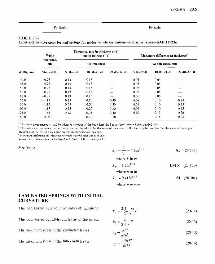
TABLE 20-2 Cross section tolerances for leaf springs for motor vehicle suspension--metric bar s i z e s m S A E J l 123a
Width tolerance,
mm
Tolerance, mm in thickness (+)a and in flatness (_)b Maximum difference in thickness c
For thickness For thickness, mm
Width, mm Minus 0.00 5.00-9.50 10.00-21.20 22.40-37.50 5.00-9.50 10.00-21.20 22.40-37.50
40.0 +0.75 0.13 0.15 0.05 0.05 45.0 +0.75 0.13 0.15 0.05 0.05 50.0 +0.75 0.13 0.15 0.05 0.05 56.0 +0.75 0.13 0.15 0.05 0.05 63.0 +0.75 0.13 0.15 0.05 0.05 75.0 + 1.15 0.15 0.20 0.30 0.08 0.10 90.0 + 1.15 0.15 0.20 0.30 0.08 0.10
100.0 + 1.15 0.15 0.20 0.30 0.08 0.10 125.0 +1.65 0.18 0.25 0.40 0.10 0.13 150.0 +2.30 0.30 0.50 0.15
0.15 0.15 0.15 0.20 0.25
a Thickness measurements shall be taken at the edge of the bar where the flat surfaces intersect the rounded edge. b This tolerance represents the maximum amount by which the thickness of the center of the bar may be less than the thickness at the edges. Thickness of the center may never exceed the thickness at the edges. c Maximum difference in thickness between the two edges of each bar. Source." Reproduced from SAE Handbook, Vol. I, 1981, courtesy SAE.
Size fac to r ksz -- 1 -- 4.66h °35 S I (20-10a)
esz
where k in m
ksz =- 1.27h °35 U S C S (20-10b)
where h in in
ksz -- 0 .415h °35 S I (20-10c)
where h in m m
LAMINATED SPRINGS WITH INITIAL CURVATURE
The load s h a r e d by g r a d u a t e d leaves o f the spr ing
The load s h a r e d by fu l l - length leaves o f the spr ing
The m a x i m u m stress in the g r a d u a t e d leaves
The m a x i m u m stress in the fu l l - length leaves
2(1 - r) F (20-11) Fg--- 2 + r
3r = F (20-12) Ff -2-~ r
c~Fl ag = lb, h 2 (20-13)
1.5c~Fl ~rf= ib, h 2 (20-14)
20 .6 CHAPTER TWENTY
Particular Formula
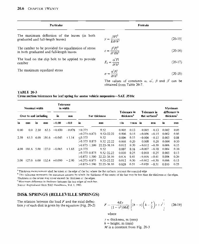
The m a x i m u m deflection of the leaves (in bo th g r a d u a t e d and full- length leaves)
/3F13
y = Eib~h3 (20-15)
The c a m b e r to be p rov ided for equal iza t ion of stress in bo th g r a d u a t e d and full- length leaves
The load on the clip bolt to be appl ied to p rov ide c a m b e r
The m a x i m u m equal ized stress
/3 ~ Fl 3
c -- ib, Eh3 (20-16)
c~'F/ F b = ib,h 2 (20-17)
~ 'F / cr = ib,h---y (20-18)
The values of cons tan t s c~, c~', /3 and /3' can be ob ta ined f rom Table 20-7.
T A B L E 20-3 Cross sect ion to lerances for l ea f spring for m o t o r vehicle s u s p e n s i o n - - S A E J 5 1 0 c
Tolerance Nominal width in width
Over to and including in mm For thickness
in mm in mm - 0 . 0 0 - 0 . 0 in mm
Maximum Tolerance in Tolerance in difference in
thickness a fiat surfaces b thickness c
+in + m m in mm in mm
0.00 0.0 2.50 63.5 +0.030 -0.076
2.50 63.5 4.00 101.6 +0.045 +1.14
4.00 101.6 5.00 127.0 +0.065 + 1.65
5.00 127.0 6.00 152.4 +0.090 +2.90
<0.375 9.52 0.005 0.13 -0.005 -0.13 0.002 0.05 >0.375-0.875 9.52-22.22 0.006 0.15 -0.006 -0.15 0.002 0.05 <0.375 9.52 0.006 0.15 -0.006 -0.15 0.003 0.08 >0.375-0.875 9.52-22.22 0.008 0.20 -0.008 -0.20 0.004 0.10 >0.875-1.500 22.22-38.10 0.012 0.30 - 0 . 0 1 2 - 0 . 3 0 0.006 0.15 <0.375 9.52 0.007 0.18 -0.007 -0.18 0.004 0.10 >0.375-0.875 9.52-22.22 0.010 0.25 -0.010 -0.25 0.005 0.13 >0.875-1.500 22.22-38.10 0.016 0.41 - 0 . 0 1 6 - 0 . 4 1 0.008 0.20 >0.375-0.875 9.52-22.22 0.012 0.30 -0.012 -0.30 0.006 0.15 >0.875-1.500 22.22-38.10 0.020 0.51 - 0 . 0 2 0 - 0 . 5 1 0.010 0.25
a Thickness measurements shall be taken at the edge of the bar where the fiat surfaces intersect the rounded edge. b This tolerance represents the maximum amount by which the thickness of the center of the bar may be less than the thickness at the edges. Thickness at the center may never exceed the thickness at the edges. c Maximum difference in thickness between the two edges of each bar. Source: Reproduced from SAE Handbook, Vol. I, 1981.
DISK SPRINGS (BELLEVILLE SPRINGS)
The re la t ion between the load F and the axial deflec- t ion y of each disk is given by the equa t ion (Fig. 20-2) I 31 F = ( l _ v 2 ) M d 2 o ( h - y ) h - 5 t + (20-19)
where
t = thickness, m (mm) h = height , m (mm) M is a cons t an t f rom Fig. 20-3

SPRINGS 20.7
, l~_ di _ . . ~ t
I~ + d0"" .I I
FIGURE 20-2 Disk spring.
The maximum stress induced at the inner edge
The maximum stress induced at the outer edge
For spring design stresses
1.0 C , ~ /
o.8 A / ,
= 0.6 / / / / / -
E:: / / ~,/" o 0.4 ¢ / . o / / / ' /~"
0.2 / / , ~ f _
/ /
/
Il l I m l
2.4
2.2
2.0 o "O t- t~
1.8 ,- O
1.6 E t~ t~
1.4 ~" O o
1.2
o l/~" 1.o 1.01.5 2.0 2.5 3.0 3.5 4.0 4.5 5.0
Ratio do/d 1
FIGURE 20-3 Constants C1, C2, and M for a disk spring. (V. L. Maleev and J. B. Hartman, Machine Design, International Textbook Company, Scranton, Pennsylvania, 1954.)
TABLE 20-4 Width and thickness of leaf springs for motor vehicle suspensionmSAE J1123a
Width, mm Thickness mm
40.0 75.0 5.00 7.10 10.00 14.00 20.00 28.00 45.0 90.0 5.30 7.50 10.60 15.00 21.20 30.00 50.0 100.0 5.60 8.00 11.20 16.00 22.40 31.50 56.0 125.0 6.00 8.50 11.80 17.00 23.60 33.50 63.0 150.0 6.30 9.00 12.50 18.00 25.00 35.50
6.70 9.50 13.20 19.00 25.50 37.50
Source: Reproduced from SAE Handbook, Vol. I, 1981.
] ,2o2o, O' i - - (1 - v 2 ) d 2 C1 h--~ -Jr- C2t
[ ( , ) ] CrO=(l_v2)d2 C 1 h- -~ C2t (20-21)
where C 1 and C2 are constants taken from Fig. 20-3
Refer to Table 20-8
600
500
400
-o 300 O ._1
200
100
0
-100
F F
i i
, -2 '~ 'M __.ro.o4o"= t ~~====~
L / /
#/; / f - - " / /
/
0 0.08 0.16 0.24 0.32 Deflection, in
FIGURE 20-3a Load-deflection curves for Belleville springs. Courtesy: Shigley, J. E. and L. D. Mitchell, Mechanical Engi- neering Design, McGraw-Hill Publishing Company, New York, 1983.

2 0 . 8 CHAPTER TWENTY
200
180
160
o-I~ 140 O O
t - O
. m
• -g 1 2 0 0
13.
u.. 100 <
0 . . J
~- 80 0
t -
40
20
q .,to % u! uo!loelJeG
061, 091, OZl, 091, 091, 0171, 0 ~ 0~I, 01.I, , , ,
/ ~ ~ ~ "~ I .j J ~ :
~m ,,_
/ -,,, ,, .
" " f ~ x x x \ \ I
O~
mmmmiBmlnimlmiImlmmm
i'
i
mru m .mm .w ummmmmmm
iNNwlialilmmmmmmmmmm
/ mimmmmmmmmmmmmmmmml 10 20 30 40 50 60 70 80 90
Deflection in % of h
Where P = load, N; PF = Flat position load, N.
. _ J 0 0 ~
100
8
u_
FIGURE 20-3b Load deflection characteristics for Belleville washers Courtesy: Jorres, R. L., Springs; Chapter 24 in Shigley, J. E. and C. R. Mischke, eds, Standards Handbook of Machine Design, McGraw-Hill Publishing Company, New York, 1986.
FIGURE 20-4 Helical spring under axial load.
SPRINGS 20.9
Particular Formula
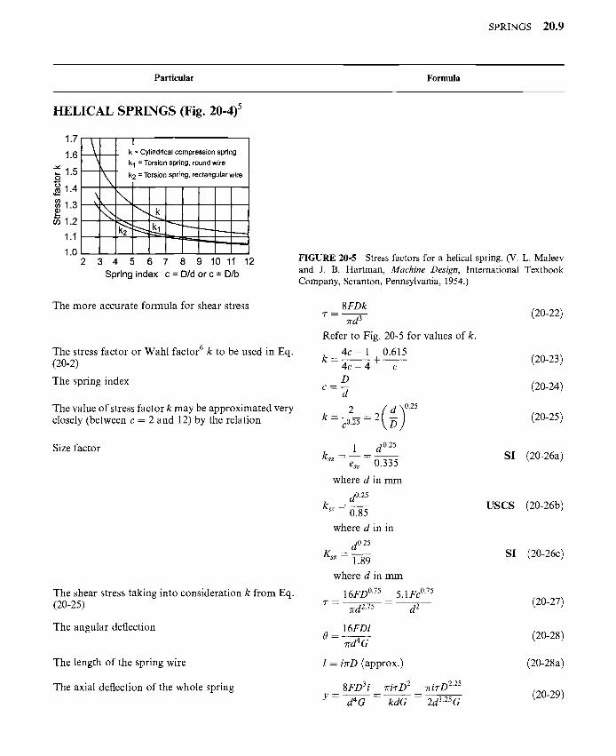
HELICAL SPRINGS (Fig. 20-4) 5
1.7
1.6. --
,_ 1.5 o O 1.4 0 0
1.3
1.2
1.1
1.0
k = Cylindrical compression spring
k I = Torsion spring, round wire \- i k2 = Torsion spring, rectangular wire , ,
~ ~ . =~.~_
3 4 5 6 7 8 9 10 11 12
Spring index c = Did or c = D/b
The more accurate formula for shear stress
The stress factor or Wahl factor 6 k to be used in Eq. (20-2)
The spring index
The value of stress factor k may be approximated very closely (between c = 2 and 12) by the relation
Size factor
The shear stress taking into consideration k from Eq. (20-25)
The angular deflection
The length of the spring wire
The axial deflection of the whole spring
FIGURE 20-5 Stress factors for a helical spring. (V. L. Maleev and J. B. Hartman, Machine Design, International Textbook Company, Scranton, Pennsylvania, 1954.)
8 F D k 7" = rrd---- T- (20-22)
Refer to Fig. 20-5 for values of k.
4 c - 1 0.615 k - - 4 c 4 t (20-23)
- - 17
D c = 7 (20-24)
k = cO.2--- 7 = 2 ~ (20-25)
1 d 0"25 k= . . . . SI (20-26a)
e= 0.335
where d in mm
d0.25 k S Z ~"
0.85
where d in in
d0.25 K S Z -- -
1.89
where d in mm
7 " - - -
16FD °75
7rd 2.75
5.1Fc 0.75
d 2
USCS (20-26b)
SI (20-26c)
(20-27)
_._. 16FDI
rrd4 G (20-28)
l = iTrD (approx.) (20-28a)
8FD 3 i rriT-D 2 rci7-D 225
Y----- d4-'---G-- k ~ - - 2d1"25-----~ (20-29)
20.10 CHAPTER TWENTY
Particular Formula
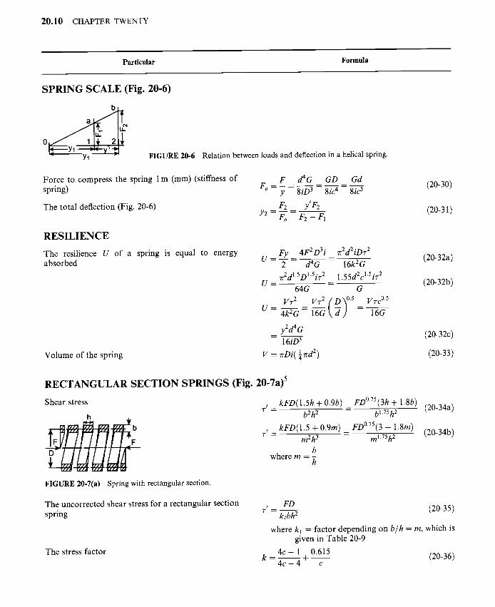
SPRING SCALE (Fig. 20-6)
-" Yl "- FIGURE 20-6 Relation between loads and deflection in a helical spring.
Force to compress the spring 1 m (mm) (stiffness of spring)
The total deflection (Fig. 20-6)
F d4G GD Gd
Fo = Y 8iD3 ~tc4 8ic3
F2 y'F2 Y2 = ~oo = F2 - F l
(20-30)
(20-31)
RESILIENCE
The resilience U of a spring is equal to energy . . Fy 4F 2D 3i 71 "2d 2iDT 2 . . . . . . absorbec~ ~ - ~ = ~ - - ---i-~2G --- t zu-~za)
7r2dl.SD1.5iT 2 1.55d2cl.SiT 2 U = = (20-32b)
64G G VT 2 VT 2 ( D )0.5 VzcO.5
U = 4k 2 G - 16G d = 16G
Volume of the spring
-- y2d4G (20-32c) 16iD 3
V = 7rDi( ~ 7rd 2) (20-33)
RECTANGULAR SECTION SPRINGS (Fig. 20-7a) 5
Shear stress
h
rTMrTiM: r' = kFD(1.5h + 0.9b)
bZh 2
k rD(1 .5 + 0.9m) T ! - - m2h 3
b where m -- -
h
FIGURE 20-7(a) Spring with rectangular section.
_ FD °75(3h + 1.8b) (20-34a) - bl.75h 2
_ FD °75 (3 + 1.8m) (20-34b) - ml.75h 2
The uncorrected shear stress for a rectangular section spring
The stress factor
r ' = FD (20-35) ktbh 2
where kl = factor depending on b/h = m, which is given in Table 20-9
k = 4 C - 1 0.615 ~ + ~ (20-36) 4c - 4 c
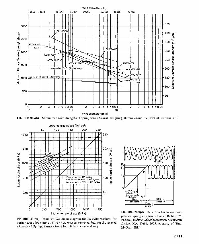
0.004 0.008 0.020 Wire Diameter (in.)
0.040 0.080 0.200 0.400 0.800
3000
2500 r-
E
2000 i ta0 E
1500 E
E E 1000 ._~
500
0
450
400 .m o9
co O
350 ,-- ¢..
¢- 300
09
250 "~ E
200 E 2~
150 E
E E
lOO N
50
1 2 3 4 5 6 7 8 9 0 2 3 4 5 6 7 8 9 1 2 3 4 5 6 7 8 9 1 0.10 1.0 10.0
Wire Diameter (mm)
FIGURE 20-7(b) Minimum tensile strengths of spring wire. (Associated Spring, Barnes Group Inc., Bristol, Connecticut)
1750
1400
Lower tensile stress (103 psi)
50 100 150 200
III|IIIIIl IIaIIIIII~I II~IIIII~II !m__III_II~I_I!
~ I _O~ ~" I
1050
t- --" ~ J / 700 ~" I / / / / L
(D f
. / /
/ 350 /
/ I! II
III I~I
/
/
250 /
/ / "
Lines shown for 106 cycles u Reduce values 10% for 107 cycles Increase values 20% for 105 cycles--
/ I 0 350 700 1050 1400 1750
Higher tensile stress (MPa)
250
200 t~
eo 0 x--
150 ~ ffl
E
lOO ~ t--
-r
50
FIGURE 20-7(c) Modified Goodman diagram for Belleville washers; for carbon and alloy steels at 47 to 49 Rc with set removed, but not shotpeened (Associated Spring, Barnes Group Inc., Bristol, Connecticut.)
F s _ _ ~P ..... II
Fu |
°L ,n,,a, ,,~1 II I l'~e"ecti°nY'" J I I eadie~U~iu~ful I / U
I.., Sol id , ,._1.., Sol id / . I r def lec t ion¥S F r ~ l e n g t h S ; I L, /f ~i '- length
FIGURE 20-7(d) Deflection for helical com- pression spring at various loads. (Richard M. Phelan, Fundamentals of Mechanical Engineering Design, New Delhi, 1975, courtesy of Tata- McGraw-Hill.)
20.11

20.12 CHAPTER TWENTY
TABLE 20-5 Width of leaf springs for motor vehicle suspension-- SAE J510C
in mm in mm in mm
1.75 44.4 2.50 63.5 4.00 101.6 2.00 50.8 3.00 76.2 5.00 127.0 2.25 57.2 3.50 88.9 6.00 152.4
Source." Reproduced from SAE Handbook, Vol. I, 1981.
TABLE 20-6 Standard sections of steel plates for laminated springs (railway rolling stocks)
Width, mm 50 63 75 90 100 115 120 125 140 150
Thickness, 10, 6, 8, 10, 6, 8, 10, 6, 8, 10, 8, 10, 11, 10, 11, 13, 16, 19 10, 13, 11, 13 11, 13, mm 13 11, 13 11, 13, 16 11, 16, 19 13, 16, 19 16, 19 16 16
T A B I E ~ . . . . . . . . . . . . . Constant in Eqs. (20-13) to (20-18)
Constant Cantilever Simply supported
12 3 2 + r 2 + r
12 3 2 + r
i 6 1 /3' 2
4(2 + r)
1.5
Particular Formula
The value of stress k may be app rox ima ted very closely by the relat ion
The spring index
The deflection
2 k = ~
C0.25
D i f b < h
C = D ~ - i f h < b
where
b = b read th of spring wire, m (mm) h = thickness of spring wire, m (mm)
2 .83 iFD 3 (b 2 + h 2)
y = b3h3G
(20-37)
(20-38)
(20-39)
SPRINGS 20.13
Particular Formula
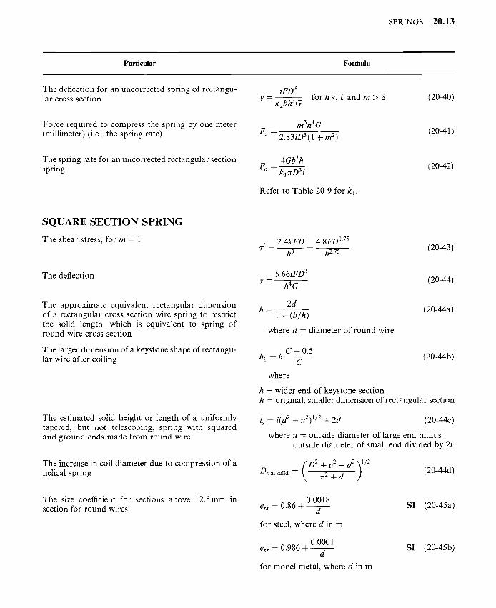
The deflection for an uncorrected spring of rectangu- lar cross section
Force required to compress the spring by one meter (millimeter) (i.e., the spring rate)
The spring rate for an uncorrected rectangular section spring
iFD 3 for h < b and m > 8 (20-40)
Y = k2bh 3G
m3h4G
F° = 2.83iD3 (1 + m 2) (20-41)
4Gb3h = ~ (20-42)
Fo k l 7rD3 i
Refer to Table 20-9 for kl.
S Q U A R E S E C T I O N S P R I N G
The shear stress, for m - 1
The deflection
The approximate equivalent rectangular dimension of a rectangular cross section wire spring to restrict the solid length, which is equivalent to spring o f round-wire cross section
The larger dimension of a keystone shape of rectangu- lar wire after coiling
The estimated solid height or length of a uniformly tapered, but not telescoping, spring with squared and ground ends made from round wire
The increase in coil diameter due to compression of a helical spring
The size coefficient for sections above 12.5 mm in section for round wires
2.4kFD 4.8FD °75 7-' = h-------5~ -- h2.7-------~ (20-43)
5.66iFD 3 y - - h4 G (20-44)
2d h --- ~ k / ' b ' h ---'~1 + (20-44a)
where d - diameter of round wire
C + 0 . 5 hi = h ~ (20-44b)
where
h = wider end of keystone section h -- original, smaller dimension of rectangular section
ls = i(d 2 - u2) 1/2 + 2d (20-44c)
where u - outside diameter of large end minus outside diameter of small end divided by 2i
Do at solid = ~2 + d (20-44d)
0.0018 esz = 0.86 +
d
for steel, where d in m
esz = 0.986 + 0.0001
for monel metal, where d in m
SI (20-45a)
SI (20-45b)

20.14 CHAPTER TWENTY
Particular Formula
The general expression for size factor
0.07 esz - 0.86 -~---~ USCS (20-45c)
for steel, where d in in
0.0043 esz = 0.986 - ~ - ~ USCS (20-45d)
for monel metal, where d in in
1.8 esz = 0.86 + --d-- SI (20-45e)
for steel, where d in mm
0.1 esz -- 0.986 + - - ~ SI (20-45f)
for monel metal, where d in mm,
ksz = 4.66h °35 where h in m SI (20-46a)
ksz = 1.27h °35 where h in in USCS (20-46b)
. . . . . . ksz=O.~iSh ~ where h i n m m - S I (20-46c)
Wire diameter 8 k F D d = ~/ (20-47)
v 7rff desz
S E L E C T I O N O F M A T E R I A L S A N D S T R E S S E S F O R S P R I N G S
For materials for springs 7
The torsional yield strength
The maximum allowable torsional stress for static applications according to Joerres 8'9'11
The maximum allowable torsional stress according to Shigley and Mischke 9
The shear endurance limit according to Zimmerli l°
The torsional modulus of rupture
Refer to Tables 20-8 and 20-10 and Figs. 20-7b and 20-7c.
0.35Crsut <-- 7.sy <-- 0.52Crsut for steels (20-47a)
0.45Osu t cold-drawn carbon steel
0.500"su t hardened and tempered 7.sy = 7.a -- t carbon and low-alloy steel
0.35Osu t austenitic stainless steel and nonferrous alloys
(20-47b)
where 7.sy = torsional yield strength, MPa (psi)
7.sy = 7.a = 0"56ffsut (20-47c)
7sT = 310 MPa (45 kpsi) (20-47d)
for unpeened springs
7.sf = 465 MPa (67.5 kpsi) (20-47e)
for peened springs
7.su -- 0.67Osut (20-47f)

SPRINGS 20.15
TABLE 20-8 Spring design stress, cr a, MPa (kpsi)
Severe service
Wire diameter, mm MPa kpsi MPa
Average service
kpsi MPa
Light
kpsi
<2.15 413.8 60 517.3 2.15-4.70 379.0 55 476.6 4.70-8.10 331.0 48 413.8 8.10-13.45 289.3 42 358.4
13.45-24.65 248.1 36 310.4 24.65-38.10 220.6 32 275.6
75 69 60 52 45 40
641.4 585.4 510.0 448.2 385.9 344.7
93 85 74 65 56 50
TABLE 20-9 Factors for helical springs with wires of rectangular cross section
Ratio b/h = m 1 1.2 1.5 2.0 Factor k 0.416 0.438 0.462 0.492 Factor k 2 0.180 0.212 0.250 0.292
2.5 3 5 10 cxz 0.516 0.534 0.582 0.624 0.666 0.317 0.335 0.371 0.398 0.424
Particular Formula
The weight of the active coil of a helical spring
For free-length tolerances, coil diameter tolerances, and load tolerances of helical compression springs
W = "~Tr2d2Di~ (20-47g) 4
where 3' = weight of coil of helical spring per unit volume
Refer to Tables 20-11 to 20-13.
DESIGN OF HELICAL COMPRESSION SPRINGS
Design stress
The size factor
The design stress
d0.35 ksz = 0.355 w h e r e d i n m
d0.25 ksz = 0.84 where d in in
d o .25 k s z = 189 w h e r e d i n m m
O" e 0 . 3 3 5 ~ r e
O-ds - - n a k s z = nadO.2----------- T
w h e r e o- e in MPa and d in m
O" e 0.84cr e O'ds = naks---~z = nadO.2---------- ~
where O" e in psi and d in in
SI (20-48a)
USCS (20-48b)
SI (20-48c)
SI (20-49a)
USCS (20-49b)

r~
o~
o~
,~
oli o
~
ell
!
.<
"~ []
,, -~.
~,
| -!
~-~
-~
~~
-~
Z
Z
Z
z z
z
z z
~O
.,,
~'~
-~
~.=
. ~
~
,-- t"4
~
,.. ,...
,-~
o
.---, ~
-~
o'~
o
~
t'-,i r-,-
r--- o
~
r'Z.
~..
~.~
. .
.
.=~
¢"4 ,--,
,--,
0 ~
r-~
o,,
r--- t'~
,,t~
¢-4
,--- ',~
,,~
~
,~
~ t-4
Z
,---
~ r-'-
_ ~
~ .~
. ~
,,0- ~
~ .-
,~-
~ ~
,~- ~
~
a _=
"~ "a
.0
~-~ ~
~ ~
~ ~'~
~ o-,
~ ~x~
~ ~
c,o
t'~
~ ~
¢'-4 c'4
,--
~'~
¢-4
t"4
~'~
• --- ~
. o
o
.-- o
o
~.
~ r--
¢'-4 t'-,l
~
t'-,I .
..
..
..
¢'4
.<
¢'4
,---
r~
~ ~
m
~ m
• ~ r--
~<
~
<
¢"4
0
20
.16
~ r-,i ~
,1
r~
r~
o o z
r,.) ~
~ ~
~.~
~ ~
e ~
!
oo
o
o
~.~
. ~-.~-.
o o
o
~ E
oo
oo
oo
~
oo
,-~
o~
o
~
~o
Z
o ~
~ .
..
..
.
~ ~
~ -~
o
~
oo
~
o
~o
o o
E
E
E
o o o
~ ~
~ o
~.
o~
.
~.o
~
~.
. .
~.
~.
.
o
0
o 5 d
a~
.,... ,~
rm
,~.g
,.o
20.17

20.18 CHAPTER TWENTY
T A B L E 20-11 Free-length tolerances of squared and ground helical compression springs a
Tolerances: ±mm/mm (in/in) of free length
Number of active Spring index (D/d)
coils per mm (in) 4 6 8 10 12 14 16
0.02 (0.5) 0.010 0.011 0.012 0.013 0.015 0.016 0.016 0.04 (1) 0.011 0.013 0.015 0.016 0.017 0.018 0.019 0.08 (2) 0.013 0.015 0.017 0.019 0.020 0.022 0.023 0.2 (4) 0.016 0.018 0.021 0.023 0.024 0.026 0.027 0.3 (8) 0.019 0.022 0.024 0.026 0.028 0.030 0.032 0.5 (12) 0.021 0.024 0.027 0.030 0.032 0.034 0.036 0.6 (16) 0.022 0.026 0.029 0.032 0.034 0.036 0.038 0.8 (20) 0.023 0.027 0.031 0.034 0.036 0.038 0.040
a For springs less than 12.7 mm (0.500 in) long, use the tolerances for 12.7 mm (0.500 in). For closed ends not ground, multiply above values by 1.7. Source: Associated Spring, Barnes Group Inc., Bristol, Connecticut.
TABLE 20-12 Coil diameter tolerances of helical compression and extension springs
Tolerances: + mm (in)
Wire diameter, Spring index (D/d)
mm (in) 4 6 8 10 12 14 16
0.38 0.05 0.05 0.08 0.10 0.13 0.15 0.18 (0.015) (0.002) (0.002) (0.003) (0.004) (0.005) (0.006) (0.007) 0.58 0.05 0.08 0.10 0.15 0.18 0.20 0.25 (0.023) (0.002) (0.003) (0.004) (0.006) (0.007) (0.008) (0.010) 0.89 0.05 0.10 0.15 0.18 0.23 0.28 0.33 (0.035) (0.002) (0.004) (0.006) (0.007) (0.009) (0.011) (0.013) 1.30 0.08 0.13 0.18 0.25 0.30 0.38 0.43 (0.051) (0.003) (0.005) (0.007) (0.010) (0.012) (0.015) (0.017) 1.93 0.10 0.18 0.25 0.33 0.41 0.48 0.53 (0.076) (0.004) (0.007) (0.010) (0.013) (0.016) (0.019) (0.021) 2.90 0.15 0.23 0.33 0.46 0.53 0.64 0.74 (0.114) (0.006) (0.009) (0.013) (0.018) (0.021) (0.025) (0.029) 4.34 0.20 0.30 0.43 0.58 0.71 0.84 0.97 (0.171) (0.008) (0.012) (0.017) (0.023) (0.028) (0.033) (0.038) 6.35 0.28 0.38 0.53 0.71 0.90 1.07 1.24 (0.250) (0.011) (0.015) (0.021) (0.028) (0.035) (0.042) (0.049) 9.53 0.41 0.51 0.66 0.94 1.17 1.37 1.63 (0.375) (0.016) (0.020) (0.026) (0.037) (0.046) (0.054) (0.064) 12.70 0.53 0.76 1.02 1.57 2.03 2.54 3.18 (0.500) (0.021) (0.030) (0.040) (0.062) (0.080) (0.100) (0.125)
Source." Associated Spring, Barnes Group Inc., Bristol, Connecticut.
S P R I N G S 2 0 . 1 9
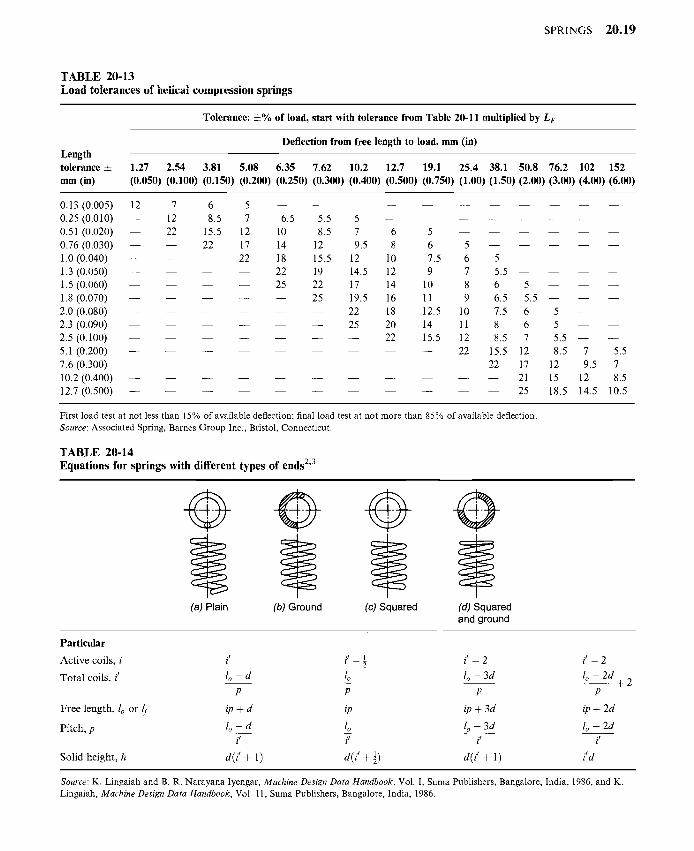
T A B L E 20-13 LOafl tolerances ot nencal compression spt-itlg~
Tolerance: +% of load, start with tolerance from Table 20-11 multiplied by L F
Length Deflection from free length to load, mm (in)
tolerance + 1.27 2.54 3.81 5.08 6.35 7.62 10.2 12.7 19.1 25.4 38.1 50.8 76.2 102 152 mm (in) (0.050) (0.100) (0.150) (0.200) (0.250) (0.300) (0.400) (0.500) (0.750) (1 .00)(1.50)(2.00)(3.00)(4.00)(6.00)
o. 13 (0.005) 0.25 (0.01 o) 0.51 (0.020) 0.76 (0.030) 1.0 (0.040) 1.3 (0.050) 1.5 (0.060) 1.8 (0.070) 2.0 (0.080) 2.3 (0.090) 2.5 (0.100) 5.1 (0.200) 7.6 (0.300) 10.2 (0.400) 12.7 (0.500)
12 7 12 22
m
u
6 5 8.5 7 6.5 5.5
15.5 12 10 8.5 22 17 14 12
22 18 15.5 22 19 25 22
25
5 7 6 5 9.5 8 6 5
12 10 7.5 6 5 14.5 12 9 7 5.5 17 14 10 8 6 5 19.5 16 11 9 6.5 5.5 22 18 12.5 10 7.5 6
25 20 14 11 8 6 22 15.5 12 8.5 7
22 15.5 12 22 17
21 - - 25
First load test at not less than 15% of available deflection; final load test at not more than 85% of available deflection. Source: Associated Spring, Barnes Group Inc., Bristol, Connecticut.
T A B L E 20-14 Equations for springs with different types of ends 2'3
5
5 5.5 8.5
12
15 18.5
7 5.5 9.5 7
12 8.5
14.5 10.5
(a) Plain (b) Ground (c) Squared (d) Squared and ground
Particular
Active coils, i
Total coils, i'
Free length, lo or If
Pitch, p
Solid height, h
i t i t 1 i t - 2 2
l o - d lo lo -3d p P p
ip + d ip ip ÷ 3d
t o - d to lo -3d i t i t i t
d( i ' + 1) d( i ' +½) d( i ' + 1)
i t - 2
lo - 2 d
P
ip + 2d
lo - 2d i I
{ d
- - ÷ 2
Source: K. Lingaiah and B. R. Narayana Iyengar, Machine Design Data Handbook, Vol. I, Suma Publishers, Bangalore, India, 1986, and K. Lingaiah, Machine Design Data Handbook, Vol. 11, Suma Publishers, Bangalore, India, 1986.

20.20 CHAPTER TWENTY
Particular Formula
TABLE 20-15 Curvature factor kc
c 3 4 6 7 8 9 10 k¢ 1.35 1.25 1.15 1.13 1.11 1.1 1.09
The actual factor of safety or reliability factor
The wire diameter for static loading
The wire diameter where there is no space limitation (D -- ca)
a___~e = 1.89a_______~ Metric (20-49c) O'ds : Ylaksz r/a d0"25
where ae in kgf/mm 2 and d in mm
where na = actual factor of safety or reliability factor
F(compressed) (20-50a) na = F(working)
free l e n g t h - fully compressed length na = free l e n g t h - working length
= y +_______~a (20-50b) Y
where y is deflection under working load, m (mm), a is the clearance which is to be added when determining the free length of the spring and is made equal to 25% of the working deflection
Generally na is chosen at 1.25.
d= 1.445 ( 6na----ff-F
=2.945(na---ff-F)°'4D°'3cre Sl (20-51a)
where F in N, ae in MPa, D in m, and d in m
d= 0"724(6na---~F) °4D°3oe
=l.48(na---~F)°'4DO'3o.e Metric (20-51b)
where F in kgf, cre in kgf/mm 2, D in mm, and d in mm
( )04 d = 6n~,___FF DO.3
Cr e
= uses \ ] O" e
where F in lbf, O'e in psi, D in in, and d in in
d= 4.64(naF) 0"57 - - C 0"43 S | (20-51d) o- e
where d in m, F in N, O'e in Pa
d -- k, (6rta-----~F) 0"57c0 '430"e U S C S (20-51e)
where d in in, F in lbf, O" e in psi
SPRINGS 20.21
t'artlcular Fo~ula
d = 1 . 7 7 ( n a F ) °s7 C 0'43 Metric or e
where d in mm, F in kgf, ae in kgf/mm 2
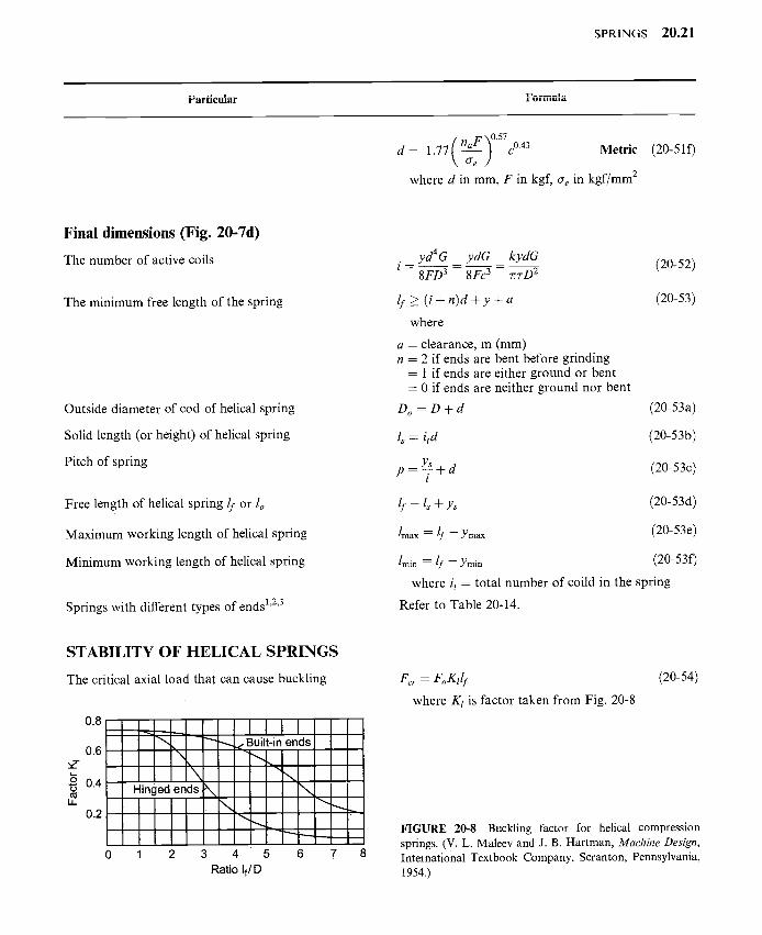
(20-510
Final dimensions (Fig. 20-7d)
The number of active coils
The minimum free length of the spring
Outside diameter of cod of helical spring
Solid length (or height) of helical spring
Pitch of spring
Free length of helical spring/f or lo
Maximum working length of helical spring
Minimum working length of helical spring
Springs with different types of ends 1'2'3
STABILITY OF HELICAL SPRINGS
The critical axial load that can cause buckling
0.8
0.6 m
L_
O "5 0.4 6 }
LI_
0.2
\
\ Hinged ends
0 1 2
I l l l ~ ,z Built-in ends
,,, \
3 4 5 6 7 Ratio If/D
yd 4 G ydG kydG i . . _ _ _ _ . . . . _
8FD 3 8Fc 3 7rv-D 2
lf >_ ( i + n ) d + y + a
where
a - clearance, m (mm) n = 2 if ends are bent before grinding
-- 1 if ends are either ground or bent = 0 if ends are neither ground nor bent
Do = D + d
ls = itd
Ys p = - - + d l
lrnax--lf--Ymax
lmin -- If -- Y min
where it = total number of coild in the spring
Refer to Table 20-14.
(20-52)
(20-53)
(20-53a)
(20-53b)
(20-53c)
(20-53d)
(20-53e)
(20-53f)
F c r - - F o K l l f
where Kt is factor taken from Fig. 20-8
(20-54)
FIGURE 20-8 Buckling factor for helical compression springs. (V. L. Maleev and J. B. Hartman, Machine Design, International Textbook Company, Scranton, Pennsylvania, 1954.)

20 .22 CHAPTER TWENTY
Particular Formula
The equivalent stiffness of springs
The critical load on the spring
The critical deflection is explicitly given by
(El)spring - - Ed 4 l
32iD(2 + v)
7r2 E d 4
F c r = 3 2 ( Z + v ) i D ( l f - Y c r )
Ycr Ycr 1 + V D = 0 2
where l = (/f - yer)
(20-55)
(20-56)
(20-57)
REPEATED LOADING (Fig. 20-9)
The variable shear stress amplitude 8D Fmax - Fmi n ra -- kw 7rd3 2
where kw = k~-kc
Refer to Table 20-15 for kc.
(20-58)
t • a I; o = I
~ :'...... 2 ... ~ l < Experimental curve
~" ~~,,'~ff~;Ik~rn: stress line
I~ ~m'~~y "~ ~ ~'~m
FIGURE 20-9 Cyclic stresses in spring. (K. Lingaiah and B. R. Narayana Iyengar, Machine Design Data Handbook, Engineering College Cooperative Society, Bangalore, India, 1962; K. Lingaiah and B. R. Narayana Iyengar, Machine Design Data Handbook, Vol. I, Suma Publishers, 1986; K. Lingaiah, Machine Design Data Handbook, Vol. II, Suma Publishers, Bangalore, India, 1986.)
The mean shear stress 8 0 Fma x -+- Fmi n (20-59) Tm = kr 7rd3 2
where k~ = 1 + 0.5/c
Design equations for repeated loadings 1'2'3
Method 1 The Gerber parabolic relation ()2
~'a + ~-m = 1 (20-60) %a rua

SPRINGS 20.23
Parti¢_nbr Formula
The Goodman straight-line relation
The Soderberg straight-line relation
~-a + "rm = 1 (20-61)
%d Tud
Ta + Tm = 1 (20-62) Tod Tyd
Method 2
The static equivalent of cyclic load Fm + Fa
The relation between o- e and af for brittle material
The static equivalent of cyclic load for brittle material
The relation between F~m, fma x and fmi n
The diameter of wire for static equivalent load
The wire diameter when there is no space limitation (D = cd)
F'm = Fm + as--A Fa (20-63a) O" o
or
F~m = Fm + as__£ Fa (20-63b) afd
(7" e = 2af (20-64)
F~m = Fm + 2Fa (20-65)
/;~m = 1 (3Fmax - Fmin) (20-66)
d = 1.45 (3na(3Fmaxo.e -- fmin))0"4D°'3 SI (20-67a)
where F in N, O e in MPa, D in m, and d in m
d = (3na(3fmax" O'e -- fmin))°'4D°'3 UNCS (20-67b)
where F in lbf, (7 e in psi, D in in, and d in in
d=O'724(3na(3Fmax- fmin)) e
Metric (20-67c)
where F in kgf, cre in kgf/mm 2, D in mm, and d in mm
d = 1.67 (3na(3fmaXo.e -- fmin))0"57C0"43 Sl (20-68a)
where F in N, cre in MPa, and d in m
d -- (3t/a(3fmaXffe - fmin)) 0"57c0"43 USCS (20-68b)
where F in lbf, O" e in psi, and d in in
d=O.64(grta(3Fmax-fmin)) 0 " 5 7 c 0 " 4 3 0 . e
Metric (20-68c)
where F in kgf, ae in kgf/mm 2, and d in mm
20.24 CHAPTER TWENTY
Particular Formula
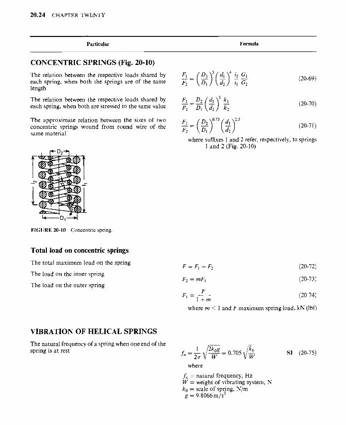
C O N C E N T R I C S P R I N G S (Fig. 20-10)
The relation between the respective loads shared by each spring, when both the springs are of the same length
The relation between the respective loads shared by each spring, when both are stressed to the same value
The approximate relation between the sizes of two concentric springs wound from round wire of the same material
F [
i
FIGURE 20-10 Concentric spring.
F__[ _ ( D3 3 dl i i 2 G, F2 -- -~l ) ( --~2 i, G2
(20-69)
F1 _ D2 { dl "~ 3 kl (20-70)
/72 -- D--~ ~, )d22 k-2
F___[ _ D 2 ) 0"75 d l ) 25
where suffixes 1 and 2 refer, respectively, to springs 1 and 2 (Fig. 20-10)
Total load on concentric springs
The total maximum load on the spring
The load on the inner spring
The load on the outer spring
F = FI + F2 (20-72)
F2 = mFl (20-73)
F (20-74) F l - - l + m where m _< 1 and F maximum spring load, kN (lbf)
V I B R A T I O N O F H E L I C A L S P R I N G S
The natural frequency of a spring when one end of the spring is at rest f~ = ~ = 0.705
where
fn = natural frequency, Hz W = weight of vibrating system, N k0 = scale of spring, N/m g = 9.8066 m/s
SI (20-75)
SPRINGS 20.25
Ii t l l i, i I b u i t l l l ~ n r m n l ~
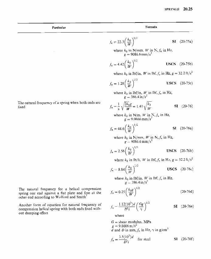
The natural frequency of a spring when both ends are fixed
The natural frequency for a helical compression spring one end against a flat plate and free at the other end according to Wolford and Smith 7
Another form of equation for natural frequency of compression helical spring with both ends fixed with- out damping effect
fn = 22.3 SI (20-75a)
where ko in N/mm, W in N, f , in Hz, g = 9086.6 mm/s 2
fn = 4.42 -~ USCS (20-75b)
where ko in lbf/in, W in lbf, f~ in Hz, g = 32.2 ft/s 2
fn-- 1.28 -~ USCS (20-75c)
where k0 in lbf/in, W in lbf, f , in Hz, g = 386.4 in/s 2
1 ~ 1 . 4 1 ~ / ~ SI (20-76) f " = T r
where ko in N/m, W in N, fn in Hz, g = 9.0866 mm/s 2
( k 0 ) 1/2 fn = 44.6 -~ SI (20-76a)
where k0 in N/mm, W in N, fn in Hz, g = 9086.6 mm/s 2
( k o ) 1/2 fn -- 2.56 -~ USCS (20-76b)
where ko in lb/ft, W in lbf, f , in Hz, g -- 32.2 ft/s 2
f~ -- 8.84 USCS (20-76c)
where ko in lbf/in, W in lbf, f , in Hz, g = 386.4 in/s 2
(20-76d)
fn = l.12(lO3)d ( Gg) 1/2 D2 i ~ SI (20-76e)
where
G = shear modulus, MPa g = 9.8006 m/s 2 d and D in mm, fn in Hz, ~, in g/cm 3
3.5(105)d fn -- D2i for steel SI (20-76f)

20 .26 CHAPTER TWENTY
Particular Formula
= D2 i ~ u s e s (20-76g)
where
G = modulus of rigidity, psi g = 386.4 in/s 2 d and D in in, fn in Hz, 3' in lbf/in 2
14(103)d f,, = D2 i for steel u s e s (20-76h)
S T R E S S W A V E P R O P A G A T I O N I N C Y L I N D R I C A L S P R I N G S U N D E R I M P A C T L O A D
The velocity of torsional stress wave in helical com- pression springs
The velocity of surge wave (Vs)
The impact velocity (Vimp)
The frequency of vibration of valve spring per minute
Gg )l /2 Vr = 10.1 - T Sl (20-76i)
where Vr in m/s, G in MPa, g = 9.8066 m/s 2, 7 in g/cm 3
Gg) 1/2 V~ = (--~- USCS (20-76j)
where V~- in in/s, G in psi, g - 386.4 in/s 2, 7 in lbf/in 3
(It varies from 50 to 500m/s.)
( g Vimp = 10.1o" 2 - ~ S| (20-76k)
(7 Vimp = 35.5 m/s for steel S!
Vim p = (7" ~ G u s e s (20-761)
o" Vimp -- 131 in/s for steel u s e s
f , = 84.627 f f f~ SI (20-77a)
where k0 in N/m, W in N
fn = 2676.12 ~/--~ Metric (20-77b)
p . , o . _ _ _
where k0 in kgf/mm, W in kgf
f~ = 530 V/-~ u s c s (20-77c)
where k0 in lbf/in, W in lbf
SPRINGS 20.27
I G ~ , I L I ~ U I 6 , 1 . 1 Formula
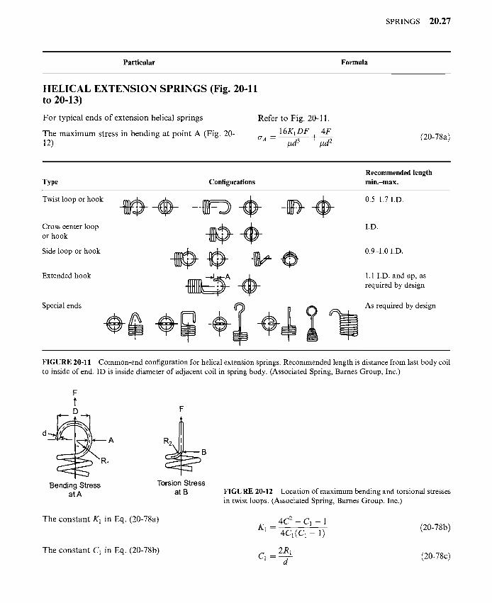
HELICAL EXTENSION SPRINGS (Fig. 20-11 to 20-13)
For typical ends of extension helical springs Refer to Fig. 20-11.
The maximum stress in bending at point A (Fig. 20- 16K1DF 4F 12) CrA = #d --------5-- + ~#d 2 (20-78a)
Type Configurations Recommended length min.-max.
Twist loop or hook
Cross center loop or hook
Side loop or hook
Extended hook
Special ends
0.5-1.7 I.D.
I.D.
0.9-1.0 I.D.
1.1 I.D. and up, as required by design
As required by design
FIGURE 20-11 Common-end configuration for helical extension springs. Recommended length is distance from last body coil to inside of end. ID is inside diameter of adjacent coil in spring body. (Associated Spring, Barnes Group, Inc.)
d A
1
Bending Stress atA
R2 B
Torsion Stress at B FIGURE 20-12 Location of maximum bending and torsional stresses
in twist loops. (Associated Spring, Barnes Group, Inc.)
The constant K1 in Eq. (20-78a)
The constant C1 in Eq. (20-78b)
4 C - C1 - 1 K1 = 4 C 1 ( C 1 - 1) (20-78b)
2R1 (20-78c) C I = d

20.28 CHAPTER TWENTY
Particular Formula
The maximum stress in torsion at point B (Fig. 20-12)
The constant C2 in Eq. (20-78d)
For extension helical spring dimensions
For R1, refer to Fig. 20-12.
8DF 4 C 2 - 1 ORB-- #d 3 4 C 2 - 4
C2 - - 2R2 d
For R2, refer to Fig. 10-12.
In practice C2 may be taken greater than 4.
Refer to Fig. 20-13.
(20-78d)
(20-78e)
Wire O,a? Gap~
-3°;:
I~ Free Length .~1 I
/ Length of I I
° r - --'1 I
/ I I Length I
,n 1 side Diar~eter
FIGURE 20-13 Typical extension-spring dimensions. (Associated Spring, Barnes Group, Inc.)
For design equations of extension helical springs
The spring rate
The stress
The design equations of compression springs may be used.
F - F i Gd 4 k0 . . . . (20-78 0 y 8D3i
where Fi = initial tension
k8FD a = #d------ 7- (20-788)
where k = stress factor for helical springs
Refer to Fig. 20-5 for k.
C O N I C A L S P R I N G S [Fig. 20-14(a)]
The axial deflection y for i coils of round stock may be computed by the relation [Fig. 20-14(a)]
The axial deflection of a conical spring made of rectangular stock with radial thickness b and an axial dimension h [Fig. 20-14(c)]
2iF(D 3 + D2D, + D2D~ + D~) y = a4 G (20-79)
7riT-(D 3 + D2D, + D2D~ + D~) Y = 4dD2kG (20-80)
y = 0.71iF(b 2 + h2)(D 3 + D2D, + D2D~ + D~)
b3h3 G
(20-81)

SPRINGS 20.29
Particular Formula
F
(a) Conical (b) Volute (c) Volute (round wire) (round wire) (rectangular wire) FIGURE 20-14 Conical and volute springs.
N O N M E T A L L I C S P R I N G S
Rectangular rubber spring (Fig. 20-15) Approximate overall dimension of the shock absorber can be obtained by (Fig. 20-15)
Spring constant K of an absorber
Dimensions of sleeve and core are found by empirical relations
L D J-~ FIGURE 20-15 Rectangular rubber spring.
T O R S I O N S P R I N G S (Fig. 20-16) 7
The maximum stress in torsion spring
The stress in torsion spring taking into consideration the correction factor k'
The deflection
The stress in round wire spring
L 7 r E ( U ) (20-82) D 2 - 2 F 2 (Fmax/F) 2 - 1
7rD2E (20-83) K = ~ L
Z 1 = 0 . 7 5 L (20-84)
D1 = 0.70D (20-85)
D 2 = 1.12D~ (20-86)
Mt F (20-87) ~ = - 2 - + 5
k'Mt 2Mt (20-88) ~ - - 2 - + D---Y
MtLD (20-89) Y= 2EI
8Mt(4k'D + d) (20-89a) o = 7rd3 D
where k' = k 1 can be taken from curve kl in Fig. 20.5
The torsional moment Mt is numerically equal to bending moment Mb.

20 .30 CHAPTER TWENTY
Particular Formula
r I I ' ~
SHORT HOOK ENDS
SPECIAL ENDS HINGE ENDS
O@ STRAIGHT OFFSET
DOUBLE TORSION ( ~ STRAIGHT TORSION
FIGURE 20-16 Common helical torsion-spring end configurations. (Associated Spring, Barnes Group, Inc.)
The stress is also given by Eq. (20-90) without taking into consideration the direct stress (F /A)
The expressions for k for use in Eq. (20-90)
Equation (20-90) for stress becomes
The angular deflection in radians
The spring rate of torsion spring
The spring rate can also be expressed by Eq. (20-95), which gives good results
a = k Mb c I
where Mb = Fr
4 C 2 + C - 1 k = ko - for outer fiber
4 C ( C + 1)
4 C 2 - C - 1 k = ki = for inner fiber
4 C ( C - 1)
32Fr (7 -- k i 7rd3
0 = 6 4 M b D i E d 4
ko = Mb 0
d4E
64Di
d 4 E ~ : ' o = ~ 10.8Di
(20-90)
(20-91a)
(20-91b)
(20-92)
(20-93)
(20-94)
(20-95)

SPRINGS 20.31
P ~ r t i e n l ~ r Formula
The allowable tensile stress for torsion springs
The endurance limit for torsion springs
Crsy=Cra=
0. 7 8Crsut
0.87Osut
O. 610"su t
cold-drawn carbon steel
hardened and tempered carbon and low-alloy steels
stainless steel and nonferrous alloys
Crsf = 538 MPa (78 kpsi)
Torsion spring of rectangular cross section
The stress in rectangular wire spring
Axial dimension b after keystoning
Another expression for stress for rectangular cross- sectional wire torsion spring without taking into consideration the direct stress (or = F / A )
The spring rate
Splined ends _d
FIGURE 20-17 Torsion bar spring
6kIMt 2 M t cr -- b2h -~ Dbh (20-96)
where U - k2 can be taken from curve k2 in Fig. 20-5
D c = ~- (20-97)
C - 0 . 5 b, = b ~ (20-98)
6kiMb o-= bh---- T - (20-99)
4C where ki = 4C - 3
ko = Mb = Ebh_____33 (20-100) 0 66Di
Torsion bar springs
For allowable working stresses for rubber compres- sion springs
Refer to Tables 20-16 and 20-17 and Fig. 20-17.
Refer to Table 20-18.

2 0 . 3 2 C H A P T E R T W E N T Y
TABLE 20-16 Design formulas for bar springs
TABLE 20-17
Factors for computing rectangular bars in torsion
Cross section of Angular Maximum bar deflection, 0, rad shear stress, 7-
Solid circular bar 584Mtl d4G
Hollow circular 584Mtl bar (d 4 - d 4 G
Square bar 407Mtl baG
Rectangular bar 57.3Mtl a
k'l bh3 G
16Mr 7rd 3
16Mtdl ~l d 4 -,t4) 4.81M t
b 3
Mt a k'22bh 2
b/h k' k'l k~2
1.0 0.675 0.140 0.208 1.2 0.759 0.166 0.219 1.5 0.848 0.196 0.231
2.0 0.930 0.229 0.246 2.5 0.968 0.249 0.258 3.0 0.985 0.263 0.267 4.0 0.997 0.281 0.282
5.0 0.999 0.291 0.291
10.0 1.000 0.312 0.231 oc 1.000 0.333 0.333
a Values of k'! and k[ can be obtained from Table 20-9.
TABLE 20-18 Suggested allowable working stresses for rubber compression springs
Limits of allowable stress
Occasional loading
Durometer hardness Area a ratio MPa
Cont. or freq. loading b
psi MPa psi
30 5 2.76 400 30 3 2.48 360
30 2 2.24 325
30 1 1.79 260 30 0.5 1.45 210 50 4 4.82 700
50 2 3.73 540 50 1 2.69 390 50 0.5 2.07 300 80 2 6.13 890 80 1 4.14 600 80 0.5 2.90 420
0.97
0.93 0.86
0.73 0.62 1.86
1.58 1.24
1.03 2.69
2.07 1.65
140
135 125
105 90
270 230 180
150 390
300 240
a Ratio of load-carrying area available for bulging or lateral expansion
SPRINGS 20.33
REFERENCES
1. Lingaiah, K. and B. R. Narayana Iyengar, Machine Design Data Handbook, Engineering College Co- operative Society, Bangalore, India, 1962.
2. Lingaiah, K., and B. R. Narayana Iyengar, Machine Design Data Handbook, Vol. I (SI and Customary Metric Units), Suma Publishers, Bangalore, India, 1986.
3. Lingaiah, K., Machine Design Data Handbook, Vol. II (SI and Customary Metric Units), Suma Publishers, Bangalore, India, 1986.
4. SAE Handbook, Springs, Vol. I, 1981. 5. Maleev, V. L., and J. B. Hartman, Machine Design, International Textbook Company, Scranton,
Pennsylvania, 1954. 6. Wahl, A. M., Mechanical Springs, McGraw-Hill Book Company, New York, 1963. 7. Associated Spring, Barnes Group Inc., Bristol, CT, USA. 8. Jorres, R. E., Springs; Chap. 24 in J. E. Shigley and C. R. Mischke, eds., Standard Handbook of Machine
Design, McGraw-Hill Book Company, New York, 1986. 9. Shigley, J. E., and C. R. Mischke, Mechanical Engineering Design, 5th ed. McGraw-Hill Company, New York,
1989. 10. Zimmerli, F. P., Human Failures in Springs Applications, The Mainspring, No. 17, Associated Spring
Corporation, Bristol, Connecticut, Aug.-Sept. 1957. 11. Shigley, J. E., and C. R. Mischke, Standard Handbook of Machine Design, McGraw-Hill Book Company, New
York, 1986. 12. Phelan, R. M., Fundamentals of Mechanical Design, Tata-McGraw-Hill Publishing Company Ltd, New Delhi,
1975. 13. Lingaiah, K., Machine Design Data Handbook of Machine Design, 2nd edition, McGraw-Hill Publishing
Company, New York, 1996). 14. Shigley, J. E., and C. R. Mischke, Standard Handbook of Machine Design, 2nd edition, McGraw-Hill
Publishing Company, New York, 1996.
BIBLIOGRAPHY
Baumeister, T., ed., Marks' Standard Handbook for Mechanical Engineers, McGraw-Hill Book Company, New York, 1978.
Black, P. H., and O. Eugene Adams, Jr., Machine Design, McGraw-Hill Book Company, New York, 1968. Bureau of Indian Standards. Chironis, N. P., Spring Design and Application, McGraw-Hill Book Company, 1961. Norman, C. A., E. S. Ault, and I. F. Zarobsky, Fundamentals of Machine Design, The Macmillan Company, New
York, 1951. Shigley, J. E., Machine Design, McGraw-Hill Book Company, 1962.
Related Documents


