NAVIGATOR 3000/3500/4000 Instruction book 67021703 - Version 2.10 US - 08.2010

Welcome message from author
This document is posted to help you gain knowledge. Please leave a comment to let me know what you think about it! Share it to your friends and learn new things together.
Transcript

NAVIGATOR 3000/3500/4000
Instruction book67021703 - Version 2.10
US - 08.2010


NAVIGATOR3000/3500/4000
Instruction book67021703 - Version 2.10
US - 08.2010
HARDI® reserves the right to make changes in design, material, or specification without notice thereof.HARDI® and other product names are registered trademarks of HARDI® Inc. in the U.S. and in other countries.


Table of contents
TOC.1
1 - WelcomeWelcome letter ......................................................................................................................................1
2 - Safety notesOperator safety .....................................................................................................................................1
General info ............................................................................................................................................................................................................... 1
Local poison information center ...........................................................................................................3
3 - DescriptionGeneral info ...........................................................................................................................................1
View ................................................................................................................................................................................................................................ 1
View ................................................................................................................................................................................................................................ 2
Identification plates .............................................................................................................................................................................................. 2
Roadworthiness ...................................................................................................................................................................................................... 3
Sprayer use ................................................................................................................................................................................................................. 3
Frame ............................................................................................................................................................................................................................. 3
Tank ................................................................................................................................................................................................................................ 3
Liquid system ........................................................................................................................................4General info - valve system .............................................................................................................................................................................. 4
Pump ............................................................................................................................................................................................................................. 4
Valves and symbols ............................................................................................................................................................................................... 4
Suction valve = Blue symbols ......................................................................................................................................................................... 4
Pressure valve = Green symbols ................................................................................................................................................................... 4
Diagram - Diaphragm Liquid system with optional extras .......................................................................................................... 5
Diagram - Centrifugal Liquid system with optional extras .......................................................................................................... 6
Filters .............................................................................................................................................................................................................................. 7
CycloneFilter ............................................................................................................................................................................................................. 7
TurboFiller (optional equipment) ................................................................................................................................................................ 8
TurboFiller suction valve (optional equipment) ................................................................................................................................. 8
TurboDeflector valve (optional equipment) ......................................................................................................................................... 8
Chemical container cleaning lever (optional equipment) ........................................................................................................... 8
Agitation valve ......................................................................................................................................................................................................... 9
EasyClean filter ......................................................................................................................................................................................................... 9
Main tank Quick Fill valve (optional equipment) ............................................................................................................................... 9
EVC control unit ...................................................................................................................................................................................................... 9
Flush tank (optional equipment) ................................................................................................................................................................. 9
Clean water tank .................................................................................................................................................................................................. 10
Hydraulic systems ...............................................................................................................................11PARALIFT™ hydraulics ....................................................................................................................................................................................... 11
Boom ...................................................................................................................................................12Boom and terminology ................................................................................................................................................................................... 12
Equipment ...........................................................................................................................................13Platform ..................................................................................................................................................................................................................... 13
Right side cover .................................................................................................................................................................................................... 13
Tank level indicator ............................................................................................................................................................................................ 13
Remote pressure gauge ................................................................................................................................................................................. 14
ChemLocker (optional equipment) ......................................................................................................................................................... 14
SafetyLocker (optional equipment) ......................................................................................................................................................... 14
Night Spraying Light (optional equipment) ....................................................................................................................................... 14
External Cleaning Device (optional equipment) ............................................................................................................................. 15
Table of contents
TOC.2
4 - Sprayer setupGeneral info ...........................................................................................................................................1
Unloading the sprayer from the truck ...................................................................................................................................................... 1
Pulling the sprayer at the tie down hooks ............................................................................................................................................. 1
Before putting the sprayer into operation ............................................................................................................................................. 1
Support jack .............................................................................................................................................................................................................. 1
Jack up the sprayer ............................................................................................................................................................................................... 2
Transmission shaft ................................................................................................................................3Operator’s safety ..................................................................................................................................................................................................... 3
P.T.O. installation ..................................................................................................................................................................................................... 3
Mechanical connections ........................................................................................................................5Hitch - adjustment ................................................................................................................................................................................................ 5
Swivel hose support ............................................................................................................................................................................................. 5
Hydraulic systems .................................................................................................................................6General info ............................................................................................................................................................................................................... 6
Requirements - tractor (SPB/SPC HY-model) ........................................................................................................................................ 6
Requirements - tractor (SPB/SPC HZ-model) ........................................................................................................................................ 6
Open center hydraulics (optional equipment) ................................................................................................................................... 7
Electrical connections ............................................................................................................................8Installation of control unit brackets ............................................................................................................................................................ 8
Road traffic lights .................................................................................................................................................................................................... 8
Power supply ............................................................................................................................................................................................................ 9
Speed transducer for tractor/sprayer ........................................................................................................................................................ 9
Liquid system ......................................................................................................................................10CycloneFilter .......................................................................................................................................................................................................... 10
Pulsation damper (if fitted) ........................................................................................................................................................................... 10
Transport .............................................................................................................................................11Adjusting boom transport position ......................................................................................................................................................... 11
Track width, axles and wheels .............................................................................................................12Altering the track width (optional combo axle) .............................................................................................................................. 12
Changing the wheel offset ........................................................................................................................................................................... 12
Boom ...................................................................................................................................................13Suspension effect adjustment (SPC only) ............................................................................................................................................ 13
Table of contents
TOC.3
5 - OperationBoom .....................................................................................................................................................1
Safety info ................................................................................................................................................................................................................... 1
Maneuvering of the SPB and SPC booms - HY-versions ................................................................................................................ 1
Maneuvering of the SPB and SPC booms - HZ-versions ............................................................................................................... 2
Single-sided folding ............................................................................................................................................................................................. 2
Liquid system ........................................................................................................................................3Filling of water ......................................................................................................................................................................................................... 3
Filling through tank lid ....................................................................................................................................................................................... 3
Filling of main tank using Quick fill (optional equipment) ........................................................................................................... 3
Filling of flush tank using Quick fill (optional equipment) ........................................................................................................... 4
Filling of clean water tank ................................................................................................................................................................................. 4
Adjustment of EVC operating unit .............................................................................................................................................................. 5
Safety precautions - crop protection chemicals ................................................................................................................................. 6
Filling chemicals through tank lid ............................................................................................................................................................... 6
Filling liquid chemicals by HARDI® TurboFiller (optional equipment) .................................................................................. 7
Filling powder chemicals by HARDI® TurboFiller (optional equipment) ............................................................................. 8
Operating the control unit while spraying ............................................................................................................................................ 9
Agitation before re-starting spraying ........................................................................................................................................................ 9
TurboFiller rinsing ............................................................................................................................................................................................... 10
Quick reference - Operation ......................................................................................................................................................................... 10
Cleaning ...............................................................................................................................................11General info ............................................................................................................................................................................................................ 11
Cleaning the tank and liquid system ...................................................................................................................................................... 12
Cleaning and maintenance of filters ....................................................................................................................................................... 12
Use of flush tank and rinsing nozzles (optional equipment) ................................................................................................... 13
Using the drain valve ........................................................................................................................................................................................ 14
Quick reference - Cleaning ............................................................................................................................................................................ 15
External cleaning - Use of External Cleaning Device (optional equipment) .................................................................. 15
Work light selector switch ............................................................................................................................................................................. 16
Spray Technique - see separate book. ................................................................................................................................................... 16
Optional extras - see separate books. ..................................................................................................................................................... 16
6 - MaintenanceLubrication ............................................................................................................................................1
General info ............................................................................................................................................................................................................... 1
Recommended lubricants ............................................................................................................................................................................... 1
Boom lubrication & oiling plan ...................................................................................................................................................................... 1
Trailer lubrication & oiling plan ..................................................................................................................................................................... 2
Service and Maintenance intervals .......................................................................................................310 hours service - Cyclone filter .................................................................................................................................................................... 3
10 hours service - EasyClean filter ................................................................................................................................................................ 4
10 hours service - In-Line filter (optional equipment) ..................................................................................................................... 4
10 hours service - Nozzle filters ..................................................................................................................................................................... 4
10 hours service - Spraying circuit ............................................................................................................................................................... 5
50 hours service - Transmission shaft ........................................................................................................................................................ 5
50 hours service - Wheel bolts and nuts ................................................................................................................................................. 5
50 hours service - Tire pressure ..................................................................................................................................................................... 5
250 hours service - Readjustment of the boom ................................................................................................................................. 5
250 hours service - Hydraulic circuit .......................................................................................................................................................... 5
250 hours service - Hoses and tubes ......................................................................................................................................................... 5
250 hours service - Wheel bearings ............................................................................................................................................................ 6
1000 hours service - Transmission shaft .................................................................................................................................................. 6
1000 hours service - Wheel bearings ......................................................................................................................................................... 6
Table of contents
TOC.4
Occasional maintenance ........................................................................................................................7General info ............................................................................................................................................................................................................... 7
Pump valves and diaphragms replacement ......................................................................................................................................... 7
Pump valves and diaphragms replacement ......................................................................................................................................... 8
Cone check/replacement for pressure regulation valve ............................................................................................................... 8
Cone check/replacement for EVC distribution valve ....................................................................................................................... 9
Level indicator adjustment .............................................................................................................................................................................. 9
Level indicator cord replacement ............................................................................................................................................................... 9
Drain valve seal replacement ...................................................................................................................................................................... 10
Nozzle tubes and fittings ............................................................................................................................................................................... 10
Adjustment of 3-way-valve ........................................................................................................................................................................... 11
Retighten the frame .......................................................................................................................................................................................... 11
Readjustment boom - general info ......................................................................................................................................................... 11
Alignment of center and inner wing sections .................................................................................................................................. 12
Alignment of inner and outer wing sections .................................................................................................................................... 12
Adjusting the front fold cable ..................................................................................................................................................................... 13
Breakaway section adjustment (SPB boom) ...................................................................................................................................... 13
Breakaway section adjustment (SPC boom) ...................................................................................................................................... 14
Check/adjust sprocket timing (SPB only) ............................................................................................................................................. 14
Adjusting boom level to ground .............................................................................................................................................................. 15
Adjusting rear cable .......................................................................................................................................................................................... 15
Adjusting center section cables ................................................................................................................................................................. 16
Jaw rubber dampers (SPC only) ................................................................................................................................................................. 16
Yaw damping ........................................................................................................................................................................................................ 17
Wear bushing replacement on boom lift ............................................................................................................................................ 17
Change of bulbs .................................................................................................................................................................................................. 17
Suspension rubber dampers (optional equipment) ..................................................................................................................... 18
Shield replacement on transmission shaft .......................................................................................................................................... 18
Replacement of transmission shaft cross journals. ........................................................................................................................ 18
Change of tire ........................................................................................................................................................................................................ 19
Safety valve activation ..................................................................................................................................................................................... 19
Off-season storage ..............................................................................................................................20Off-season storage program ........................................................................................................................................................................ 20
Preparing the sprayer for use after storage ........................................................................................................................................ 21
Spare parts ..........................................................................................................................................22Spare parts ............................................................................................................................................................................................................... 22
7 - Fault findingOperational problems ...........................................................................................................................1
General info ............................................................................................................................................................................................................... 1
Liquid system ......................................................................................................................................................................................................... 2
Hydraulic system - I.A.H. .................................................................................................................................................................................. 3
Mechanical problems ............................................................................................................................4Mechanical problems ......................................................................................................................................................................................... 4
Emergency operation - Liquid system ...................................................................................................................................................... 4

Table of contents
TOC.5
8 - Technical specificationsDimensions ............................................................................................................................................1
General info ............................................................................................................................................................................................................... 1
Overall dimensions ............................................................................................................................................................................................... 1
Tank capacities ...................................................................................................................................................................................................... 1
Weight .......................................................................................................................................................................................................................... 2
Wheel and axle dimensions ........................................................................................................................................................................... 2
Specifications ........................................................................................................................................3Diaphragm pumps ............................................................................................................................................................................................. 3
........................................................................................................................................................................................................................................... 3
Centrifugal pumps .................................................................................................................................4Pump model ACE 206 hydraulic ................................................................................................................................................................... 4
Pump model ACE 304 hydraulic ................................................................................................................................................................... 4
Filters and nozzles ................................................................................................................................................................................................. 4
Temperature and pressure ranges .............................................................................................................................................................. 4
Power consumption ........................................................................................................................................................................................... 4
Tire pressure ............................................................................................................................................................................................................. 4
Materials and recycling .........................................................................................................................5Disposal of the sprayer ....................................................................................................................................................................................... 5
Electrical connections ............................................................................................................................6Electrical connections for SPRAY II .............................................................................................................................................................. 6
EVC .................................................................................................................................................................................................................................. 7
Plug positions for HZ hydraulics ................................................................................................................................................................... 8
Road traffic lights .................................................................................................................................................................................................... 8
Charts ....................................................................................................................................................9Boom hydraulics - HY .......................................................................................................................................................................................... 9
Boom hydraulics - HZ .......................................................................................................................................................................................... 9
Boom hydraulics - DH ...................................................................................................................................................................................... 10
Electrical specifications for boom and work light .......................................................................................................................... 11
9 - WarrantyWarranty policy and conditions ............................................................................................................1

Table of contents
TOC.6
1.1
1 - Welcome
Welcome letter
Dear New HARDI® Owner,
Thank you for purchasing your new HARDI® product and welcome to the ever-increasing family of proud HARDI® owners.
HARDI® is the leading sprayer company in offering growers strong, reliable products made for the widest range of
applications worldwide. Quality, reliability, and resale value make the HARDI® product line the preferred product line of
customers both in North America as well as worldwide. Our guiding principle is to provide the highest level of customer
satisfaction and long term value in the marketplace today. We have developed a very high level of customer loyalty in the
marketplace which we are very proud of and strive every day to maintain and to continue to grow.
HARDI® is your specialist in spraying and we spend all of our time and keep all of our focus on spraying. We do not share our
resources between other types of products or compromise on anything in providing the best quality sprayers to the market
today. We can provide the latest in technology with our products if desired, or allow them to operate with the technology
that you already use on other products in most cases. You get to decide that, and what best suits your needs. We feel that
you, our customer, are the best suited to answer that question for your operation. Either way, you decide, and we will try and
help make it happen for you.
Our broad spectrum of product offerings, from the ruggedly simple models we build to our highly sophisticated models,
the built-in HARDI® strength and reliability ensures a low cost of ownership. HARDI® sprayers are all based on a functional
design concept of being as simple to operate as possible and to meet our customers’ requirements for all their application
needs.
Please take the time to thoroughly read the Operator’s Manual before using your equipment. You will find many helpful hints
as well as important safety and operation information.
Some of the features on your HARDI® sprayer were suggested by growers. There is no substitute for “on farm” experience
and we invite your comments and suggestions. If any portion of this instruction book remains unclear after reading it,
contact your HARDI® dealer or service personnel for further explanation before using the equipment.
For Product, Service or Warranty Information please contact your local HARDI® dealer.- Please use the HARDI® Customer Service number: 1-866-770-7063
- Or send your email to [email protected]
HARDI® NORTH AMERICA INC.
Visit us online at: www.hardi-us.com1500 West 76th St.
Davenport, Iowa 52806
Phone: (563) 386-1730
Fax: (563) 386-1280
Sincerely,
Wayne Buchberger
President

1 - Welcome
1.2
2.1
2 - Safety notes
Operator safety
€ This symbol means DANGER. Be very alert as your safety is involved!
± This symbol means WARNING. Be alert as your safety can be involved!
This symbol means ATTENTION. This guides to better, easier and safer operation of your sprayer!
General info
Note the following recommended precautions and safe operating practices.
€ Read and understand this instruction book before using the equipment. It is equally important that other operators
of this equipment read and understand this book.
€ Local law may demand that the operator is certified to use spray equipment. Adhere to the law.
€ Wear protective clothing.
€ Rinse and wash equipment after use and before servicing.
€ Never service or repair the equipment while it is operating.
€ Always replace all safety devices or shields immediately after servicing.
€ Do not eat, drink or smoke while spraying or working with contaminated equipment.
€ Wash and change clothes after spraying.
Wash tools if they have become contaminated.
€ In case of poisoning, immediately seek medical advice. Remember to identify chemicals used.
€ Keep children away from the equipment.
€ If any portion of this instruction book remains unclear after reading it, contact your HARDI® dealer for further
explanation before using the equipment.
€ Be careful not to hit people or surroundings when maneuvering the sprayer, especially when backing.
€ Slow down when driving in uneven terrain, as the machine might be in risk of turning over.
€ Pressure test with clean water prior to filling with chemicals.
€ Disconnect electrical power before servicing and depressurize equipment after use and before servicing.
€ Do not attempt to enter the tank.
€ Do not go under any part of the sprayer unless it is secured. The boom is secure when placed in the transport
brackets.
€ If an arc welder is used on the equipment or anything connected to the equipment, disconnect power leads before
welding. Remove all inflammable or explosive material from the area.

2 - Safety notes
2.2
€ The External Cleaning Device should not be used if important parts of the equipment have been damaged, including
safety devices, high pressure hoses, etc.
2 - Safety notes
2.3
Local poison information center
€ If you live anywhere in the United States, the following toll free number will connect you to your Local Poison
Information Center.
PHONE NO. 1 - 800 - 222 - 1222
€ If you live outside the United States, find the number for the poison control center in your phone book and write it
in the space below:
PHONE NO._______ - _______ - __________
€ Keep a list, in the space provided below, of all the chemicals that you have in use.
1. _______________________________________________________________________________________________
2. _______________________________________________________________________________________________
3. _______________________________________________________________________________________________
4. _______________________________________________________________________________________________
5. _______________________________________________________________________________________________
6. _______________________________________________________________________________________________
7. _______________________________________________________________________________________________
8. _______________________________________________________________________________________________
9. _______________________________________________________________________________________________
10. ______________________________________________________________________________________________

2 - Safety notes
2.4

3.1
3 - Description
General info
View
1. Tank tube riser pipe lid
2. Flush tank level indicator
3. Main tank level indicator
4. Main tank lid
5. EasyClean clogging indicator
6. Spray pressure gauge
7. Clean water tank lid
8. SafetyLocker
9. Pump
10. Clevis Hitch
11. Support jack
12. Step to platform
13. Agitation valve
14. Pressure SmartValve
15. External Filling ON/OFF valve
16. Suction valve
17. External Filling coupler
18. EasyClean filter
19. Flush tank coupler
20. TurboFiller valves
21. TurboFiller
3 - Description
3.2
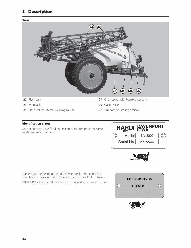
View
Identification plates
An identification plate fitted on the frame indicates producer name,
model and serial number.
Frame, boom center frame and other main steel components have
identification plates indicating type and part number. (not illustrated)
REFERENCE NO: is the main reference number of the complete machine
22. Flush tank
23. Main tank
24. Hose reel for External Cleaning Device
25. ChemLocker with FoamMarker tank
26. CycloneFilter
27. Support jack storing position
3 - Description
3.3
Roadworthiness
When driving on public roads and other areas where the highway code applies, or areas with special rules and regulations
for marking and lights on implements, you should observe these and equip implements accordingly.
ATTENTION! Max. driving speed is 25 mph (40 km/h). Be aware that this may differ due to local law. Contact local
authorities for information of max. driving speeds!
Sprayer use
The HARDI® sprayer is for the application of crop protection chemicals and liquid fertilizers. The equipment must only be
used for this purpose. It is not allowable to use the sprayer for other purposes. If no local law demands that the operator
must be certified to use spray equipment, it is strongly recommended to be trained in correct plant protection and in safe
handling of plant protection chemicals to avoid unnecessary risk for persons and the environment when doing your spray
job.
Frame
Very strong and compact frame which also has a strong chemical and weather resistant electrostatic powder coat. Screws,
nuts, etc. have been DELTA-MAGNI treated to be resistant to corrosion.
Tank
The main tank made of impact-proof, UV-resistant and chemical resistant polyethylene, has a purposeful design with no
sharp corners for easy cleaning. Nominal contents 800 gal (3000 model), 1000 gal (3500 model) or 1200 gal (4000 model). A
large, easy to read tank contents indicator is placed beside the platform and is visible from the tractor cabin. The filling hole
is placed so it can be accessed from the platform. This ensures an easy access for the filling, cleaning of the tank, etc. The
sprayer can also be equipped with a flush tank and a clean water tank.

3 - Description
3.4
Liquid system
General info - valve system
All functions of the spray circuits are operated via the centrally situated valve system with color coded pictorial symbols for
easy operation.
Pump
Diaphragm pump with easily accessible valves and diaphragms. Model 1303 with 3 diaphragms, 540 r.p.m. (6 splines). Model
363 or 463 with 6 diaphragms. Standard = 540 r.p.m. (6 splines). Optional = 1000 r.p.m. (20 or 21 splines).
Valves and symbols
The valves at the valve system are distinguished by colored identification discs on the function labels. Symbols
corresponding to every possible function of use are located on the discs for easy identification and operation. A function is
activated by turning the handle towards the desired function.
ATTENTION! If a valve is too tight to operate - or to loose (= liquid leakage) - the valve needs to be serviced. Please see
the section ‘Maintenance’ for further information.
Suction valve = Blue symbols
This valve is to select suction from main tank or from the flush tank. The
handle is turned so the label for required function is directed to the
indicator. If handle is turned to vertical position (indicator not pointing
at a label) then the valve is closed.
Pressure valve = Green symbols
The active function is indicated by the indicator.
Suction from main tank Suction from flush tank
(optional equipment)
Spraying Internal tank cleaning
(Rinsing nozzle) (optional
equipment)External tank cleaning
(Spray gun)
(optional equipment)

3 - Description
3.5
Diagram - Diaphragm Liquid system with optional extras
1. Pump
2. EasyClean filter
3. Suction Valve Main tank/Flush Tank
4. Pressure control valve
5. Pressure SmartValve
6. CycloneFilter
7. Return line for boost function
8. Return pressure drop
9. Return pressure equalization
10. Distribution valves
11. Pressure gauge
12. Spray boom
13. Agitation valve
14. Agitation tube
15. Tank tube for return lines (riser pipe)
16. One-way valve
17. Safety valve
18. Tank tube riser pipe
19. Tank rinsing nozzles
20. Flush Tank
21. Flush Tank Quick Fill coupler
22. Valve block TurboFiller
23. TurboFiller
24. Ejector for TurboFiller
25. Tank tube for Turbofiller
26. Main Tank Quick Fill coupler
27. Main Tank Quick Fill valve
28. Main Tank Quick Fill hose to tank inlet

3 - Description
3.6
Diagram - Centrifugal Liquid system with optional extras
1. Pump
2. EasyClean filter
3. Suction Valve Main tank/Flush Tank
4. Pressure control valve
5. Pressure SmartValve
6. CycloneFilter
7. Return line for boost function
8. Return pressure drop
9. Return pressure equalization
10. Distribution valves
11. Pressure gauge
12. Spray boom
13. Agitation valve
14. Agitation tube
15. Tank tube for return lines (riser pipe)
16. One-way valve
17. Tank tube riser pipe
18. Tank rinsing nozzles
19. Flush Tank
20. Flush Tank Quick Fill coupler
21. Valve block TurboFiller
22. TurboFiller
23. Ejector for TurboFiller
24. Tank tube for Turbofiller
25. Main Tank Quick Fill coupler
26. Main Tank Quick Fill valve
27. Main Tank Quick Fill hose to tank inlet
3 - Description
3.7
Filters
An EasyClean suction filter is fitted in the working zone. It has a built-in valve that closes when the filter is opened for
inspection or cleaning.
A Cyclone pressure filter is fitted to the sprayers right side just in front of the ChemLocker (optional equipment). It has a built-
in self-cleaning function.
In-line pressure filters can be fitted at each boom section as an option.
Nozzle filters are fitted at each nozzle.
All filters should always be in use and their function checked regularly. Pay attention to the correct combination of filter and
mesh size (see “Spray Technique” book).
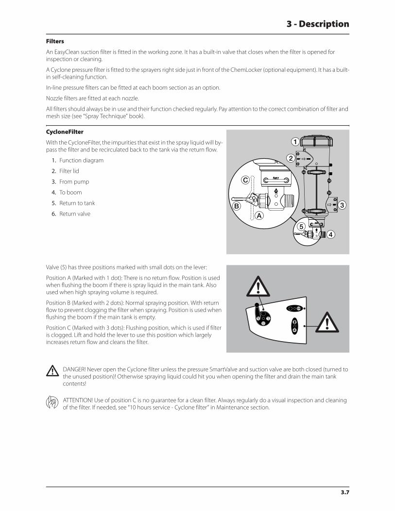
CycloneFilter
With the CycloneFilter, the impurities that exist in the spray liquid will by-
pass the filter and be recirculated back to the tank via the return flow.
1. Function diagram
2. Filter lid
3. From pump
4. To boom
5. Return to tank
6. Return valve
Valve (5) has three positions marked with small dots on the lever:
Position A (Marked with 1 dot): There is no return flow. Position is used
when flushing the boom if there is spray liquid in the main tank. Also
used when high spraying volume is required.
Position B (Marked with 2 dots): Normal spraying position. With return
flow to prevent clogging the filter when spraying. Position is used when
flushing the boom if the main tank is empty.
Position C (Marked with 3 dots): Flushing position, which is used if filter
is clogged. Lift and hold the lever to use this position which largely
increases return flow and cleans the filter.
€ DANGER! Never open the Cyclone filter unless the pressure SmartValve and suction valve are both closed (turned to
the unused position)! Otherwise spraying liquid could hit you when opening the filter and drain the main tank
contents!
ATTENTION! Use of position C is no guarantee for a clean filter. Always regularly do a visual inspection and cleaning
of the filter. If needed, see “10 hours service - Cyclone filter” in Maintenance section.

3 - Description
3.8
TurboFiller (optional equipment)
The TurboFiller is situated in the working zone on the sprayer’s left side.
When being used, it should be unlocked by pulling the handle (A)
(situated to the right of the TurboFiller) and pushed down (B) by
grabbing the handle on the TurboFiller until it clicks into the locked
down-position.
After use, the TurboFiller is retracted by unlocking the handle (A)
(situated to the right of the TurboFiller) and pulling it back up until it
clicks into the locked storing position.
± WARNING! Before releasing the lock (A) always keep a hand on
the grip to avoid abrupt movement of the TurboFiller!
TurboFiller suction valve (optional equipment)
The valve is used simultaneously with the TurboFiller. The valve is the
lowest valve situated to the left side of the TurboFiller and is activated in
two ways. Push the valve lever down to get a quick suction out of the
hopper. Lift the lever to lock it in the open position for continuous
suction from the hopper into the main tank. Open the valve when
chemicals are going to be filled into the TurboFiller.
TurboDeflector valve (optional equipment)
This TurboDeflector valve activates the Vortex flushing of the TurboFiller.
The valve is the middle valve situated to the left side of the TurboFiller
and is activated in two ways. Push the valve lever down to get a quick
flush in the hopper. Lift the lever to lock it in the open position for
continuous liquid rotation in the hopper.
Chemical container cleaning lever (optional equipment)
The upper lever located to the left of TurboFiller is used for two
purposes:
When TurboFiller lid is open: For cleaning empty containers. Put
container over the rotating rinsing nozzle in the middle of the
TurboFiller to rinse inside of the container.
When TurboFiller lid is closed: Use the Chemical Container Cleaning
lever to rinse the hopper after filling of chemicals has ended.
€ DANGER! Do not press lever unless the multi-hole nozzle is covered by a container or the TurboFiller lid is closed to
avoid spray liquid hitting the operator.
Filling chemicals without
TurboDeflection
Start TurboDeflector
Chemical container cleaning

3 - Description
3.9
Agitation valve
With the adjustable Agitation valve it is possible to combine spraying
with a high volume rate at high pressure with agitation at the same time.
This is controlled continuously by the valve: The valve is marked with an
arrow on the disc that indicates the amount of liquid that passes
through the valve. If the handle is turned to a position near the tip of the
arrow, then only a small amount of liquid is allowed to pass the valve
resulting in less agitation. Otherwise, if the handle is turned to a position
in the wide end of the arrow, then a large amount of liquid will pass the
valve resulting in a more agitation.
EasyClean filter
The EasyClean filter is fitted in the working zone. It has a built-in valve
that automatically closes when the filter is opened for inspection and
cleaning. To open filter, turn it counterclockwise and pull it up, like
shown on picture.
Beside the spray pressure gauge on the platform, an EasyClean clogging
indicator is located.
Green indicator: No cleaning necessary.
Yellow indicator: It is possible to finish an ongoing spraying job and then
clean filter afterwards.
Red indicator: Clean EasyClean filter immediately, as filter is clogged.
Main tank Quick Fill valve (optional equipment)
This valve is used when filling the main tank from an external water
supply (i.e. overhead fill tank). Activating valve starts/stops the filling
process when a pressurized filling hose is attached to the main tank
Quick Fill coupler.
EVC control unit
EVC - Electrical Valve Control. The ON/OFF is linked to the section valves, which results in a very quick response to ON/OFF.
The operating unit is of modular design and is electrically controlled via a remote control box. The unit has a built-in HARDI
MATIC.
Flush tank (optional equipment)
A flush tank can be mounted to the rear of the sprayer. Tank is made of impact-proof and chemical resistant polyethylene.
Nominal content: appr. 130 gal (500 liters).
Adjustable Agitation
Quick Fill from external tank

3 - Description
3.10
Clean water tank
A clean water tank is integrated into the right side cover which is fitted
above the Cyclone filter. It is accessed for filling at the sprayer’s right side
when entering the platform (see subject “Platform”). The ball valve is
located on the valve cover below the EasyClean filter on sprayer’s left
side.
The water from this tank is for hand washing, cleaning of clogged
nozzles etc. Only fill the clean water tank with clean water.
Capacity: appr. 5 gal (20 liters).
± WARNING! Although the clean water tank is only filled with clean water, this water must never be used for drinking.
3 - Description
3.11
Hydraulic systems
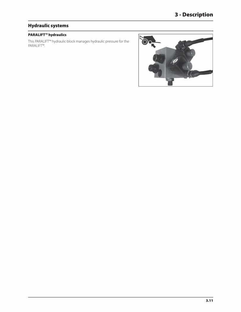
PARALIFT™ hydraulics
This PARALIFT™ hydraulic block manages hydraulic pressure for the
PARALIFT™.
3 - Description
3.12
Boom
Boom and terminology
Both the SPB boom and the SPC boom are available in two different hydraulic system versions:
1. SPB-HY & SPC-HY
These type of booms are operated directly via the tractor hydraulics. These models feature hydraulic lift cylinder for boom
height adjustment and two cylinders for simultaneous boom wing fold and unfold.
2. SPB-HZ & SPC-HZ
These type of booms have two boom wing tilt cylinders that give the ability to obtain individual boom wing tilt as well as
individual boom wing fold. These models feature hydraulic lift cylinder for boom height adjustment controlled by the
hydraulic control box.
The hydraulics on the SPB-HZ and SPC-HZ are controlled via the hydraulic control box.
Outer sections incorporate spring loaded breakaway and all booms have bi-fold wings.
The SPB boom is available in 45’, 50’, 60’ & 66’ working widths.
The SPC boom is available in 80’, 88’, 90’ & 100’ working widths.
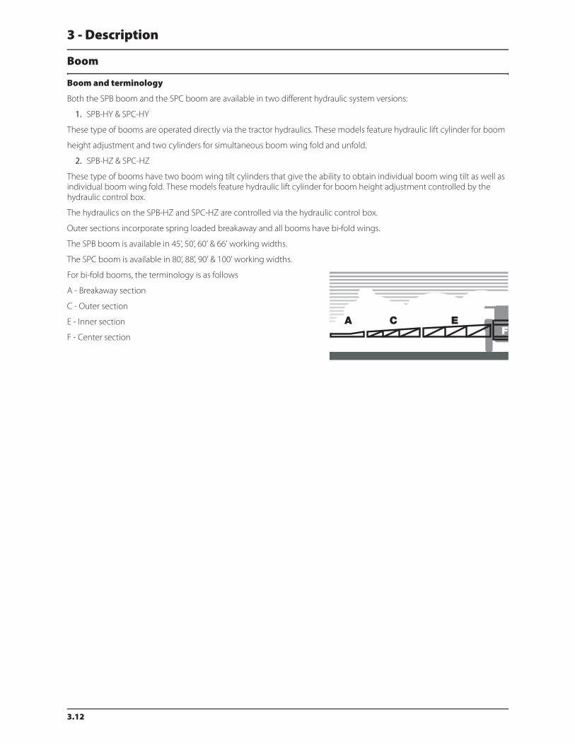
For bi-fold booms, the terminology is as follows
A - Breakaway section
C - Outer section
E - Inner section
F - Center section

3 - Description
3.13
Equipment
Platform
To get access to the platform, lift and swing the step (G) on the drawbar
out until it clicks into locked out-position. To retract step, then lift and
swing step to retracted locked in-position.
The pressure regulation valve (E) and the Agitation valve (F) are situated
in front of the platform floor. The platform gives access to the clean
water tank lid (D), the main tank lid (A). Also the main tank drain valve (C)
can be operated from the platform. The pressure gauge (B) and
EasyClean clogging indicator (B) are visible at the top of the platform.
By removing the platform floor, the valve components are accessible.
Right side cover
The right side cover is opened by turning the handle in the lower rear
corner of the cover and lifting the cover up. Lifting the right side cover
gives access to the Jobcom (A) and the box for work and road lights (B).
The clean water tank is integrated to the side cover and is filled from the
platform when right side cover is closed.
ATTENTION! Only open the right side cover when the clean water
tank is empty!
Tank level indicator
The actual fluid level in the main tank can be observed on the tank level
indicator. The scale is displayed in US gallons (liters optional).
The level indicator is only intended as a guide for the tank level. The
accuracy for the level is within 5% when the tank is above 20% filled and
within 7.5% when the tank is below 20% filled.
Just behind the main tank scale, a level indicator for the flush tank is
attached to the frame. This is intended as a guide to see if flush tank is
full or empty. When the indicator ball is at the top, then the flush tank is
full.
3 - Description
3.14
Remote pressure gauge
The remote pressure gauge is integrated in the platform. This gauge
measures the working pressure in the boom tubes as close to the
nozzles as possible.
The outputs stated in the nozzle charts are always based on the pressure
measured at the nozzle. Always adjust pressure when calibrating and
spraying according to readings at the remote pressure gauge.
ChemLocker (optional equipment)
A ChemLocker for storage of chemical containers etc. can be mounted
on the sprayer’s right side.
If the optional FoamMarker is installed, then the FoamMarker tank is
placed into the ChemLocker.
Max. load 225 lbs./25 gal. (100 Kgs./100 liters).
SafetyLocker (optional equipment)
The locker is integrated to the left side of the platform and is accessible
behind the left side cover. It is for the purpose of storing non-
contaminated protective gear, soap for hand washing etc. The locker is
split in two compartments for the separation of clean clothes from
gloves with risk of contamination.
± WARNING! Although this locker is meant for storing nontoxic
items, it must never be used for storing food, beverage or other
things meant for consumption.
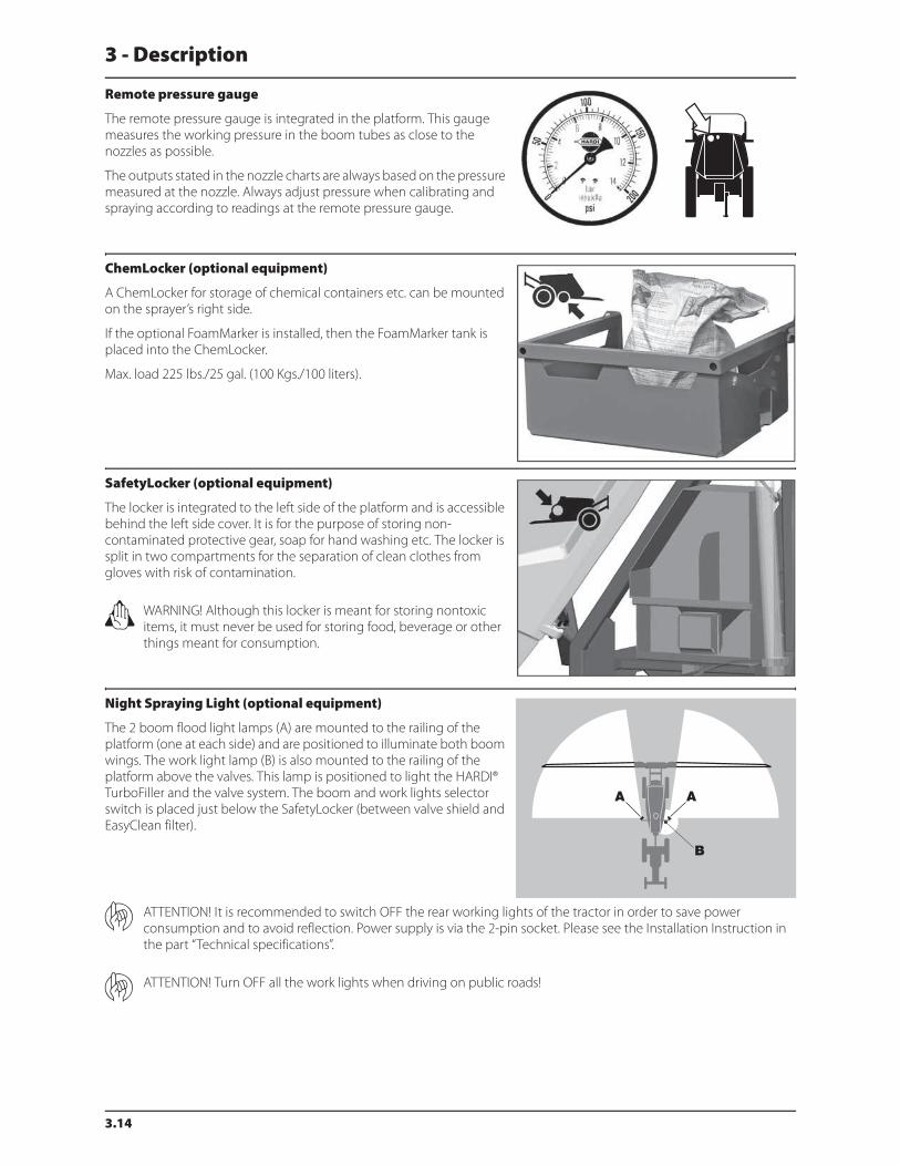
Night Spraying Light (optional equipment)
The 2 boom flood light lamps (A) are mounted to the railing of the
platform (one at each side) and are positioned to illuminate both boom
wings. The work light lamp (B) is also mounted to the railing of the
platform above the valves. This lamp is positioned to light the HARDI®
TurboFiller and the valve system. The boom and work lights selector
switch is placed just below the SafetyLocker (between valve shield and
EasyClean filter).
ATTENTION! It is recommended to switch OFF the rear working lights of the tractor in order to save power
consumption and to avoid reflection. Power supply is via the 2-pin socket. Please see the Installation Instruction in
the part “Technical specifications”.
ATTENTION! Turn OFF all the work lights when driving on public roads!

3 - Description
3.15
External Cleaning Device (optional equipment)
This equipment comprises of a hose reel and spray gun used to clean
the complete sprayer externally in the field with clean water. The
External Cleaning Device is located on the sprayer’s right side just
behind the Chemlocker.
± WARNING! This cleaner produces a high pressure spray. Incorrect
use may result in personal injuries!
€ DANGER! For the safety of yourself and others, the following rules
should always be observed:
Never point the water jet at people, animals, electrical installations or
other sensitive objects.
Never try to clean clothing or footwear which you or other people wear.
Never work with bare feet or sandals.
It is recommended to wear goggles during the work.
It is recommended that the user or anyone near the cleaning place protects himself against particles bouncing up during
the cleaning.

3 - Description
3.16
4.1
4 - Sprayer setup
General info
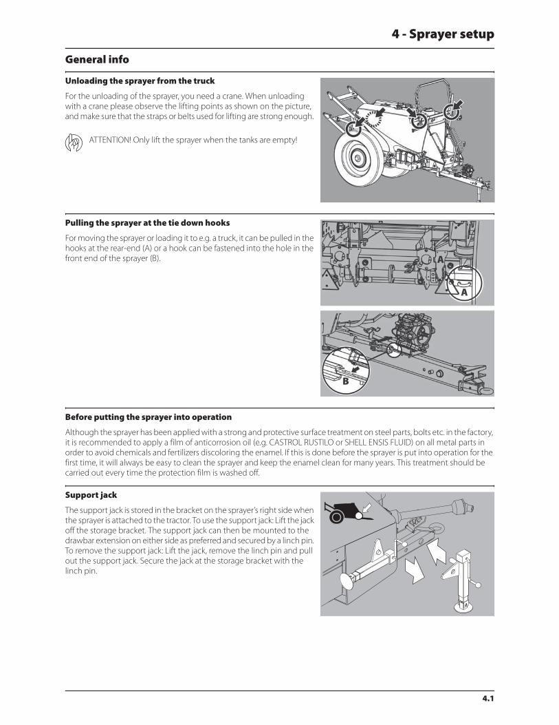
Unloading the sprayer from the truck
For the unloading of the sprayer, you need a crane. When unloading
with a crane please observe the lifting points as shown on the picture,
and make sure that the straps or belts used for lifting are strong enough.
ATTENTION! Only lift the sprayer when the tanks are empty!
Pulling the sprayer at the tie down hooks
For moving the sprayer or loading it to e.g. a truck, it can be pulled in the
hooks at the rear-end (A) or a hook can be fastened into the hole in the
front end of the sprayer (B).
Before putting the sprayer into operation
Although the sprayer has been applied with a strong and protective surface treatment on steel parts, bolts etc. in the factory,
it is recommended to apply a film of anticorrosion oil (e.g. CASTROL RUSTILO or SHELL ENSIS FLUID) on all metal parts in
order to avoid chemicals and fertilizers discoloring the enamel. If this is done before the sprayer is put into operation for the
first time, it will always be easy to clean the sprayer and keep the enamel clean for many years. This treatment should be
carried out every time the protection film is washed off.
Support jack
The support jack is stored in the bracket on the sprayer’s right side when
the sprayer is attached to the tractor. To use the support jack: Lift the jack
off the storage bracket. The support jack can then be mounted to the
drawbar extension on either side as preferred and secured by a linch pin.
To remove the support jack: Lift the jack, remove the linch pin and pull
out the support jack. Secure the jack at the storage bracket with the
linch pin.
4 - Sprayer setup
4.2
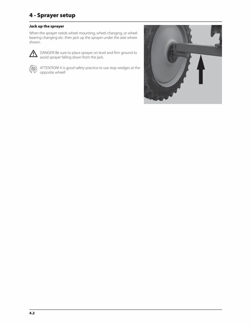
Jack up the sprayer
When the sprayer needs wheel mounting, wheel changing, or wheel
bearing changing etc. then jack up the sprayer under the axle where
shown.
€ DANGER! Be sure to place sprayer on level and firm ground to
avoid sprayer falling down from the jack.
ATTENTION! It is good safety practice to use stop wedges at the
opposite wheel!
4 - Sprayer setup
4.3
Transmission shaft
Operator’s safety
1. Always STOP ENGINE before attaching the transmission shaft to tractor P.T.O. - most tractor P.T.O. shafts can be rotated
by hand to facilitate spline alignment, when engine is stopped.
2. When attaching the shaft, make sure that the snap lock is FULLY ENGAGED - push and pull shaft until it locks.
3. Always keep protection guards and chains intact and make sure that it covers all rotating parts, including CV-joints at
each end of the shaft. Do not use without protection guard.
4. Do not touch or stand on the transmission shaft when it is rotating - safety distance: 5’ (1.5 meter). Also NEVER cross
over a rotating P.T.O. shaft to reach the other side of the sprayer.
5. Prevent protection guards from rotating by attaching the chains allowing sufficient slack for turns.
6. Make sure that protection guards around tractor P.T.O. and implement shaft are intact.
7. Always STOP ENGINE and remove the ignition key before carrying out maintenance or repairs to the transmission shaft
or implement.
€ DANGER! ROTATING TRANSMISSION SHAFTS WITHOUT PROTECTION GUARDS ARE FATAL.
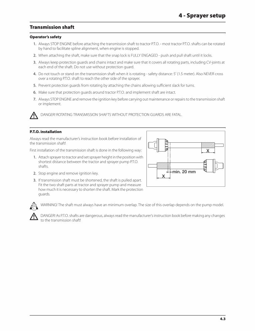
P.T.O. installation
Always read the manufacturer’s instruction book before installation of
the transmission shaft!
First installation of the transmission shaft is done in the following way:
1. Attach sprayer to tractor and set sprayer height in the position with
shortest distance between the tractor and sprayer pump P.T.O.
shafts.
2. Stop engine and remove ignition key.
3. If transmission shaft must be shortened, the shaft is pulled apart.
Fit the two shaft parts at tractor and sprayer pump and measure
how much it is necessary to shorten the shaft. Mark the protection
guards.
± WARNING! The shaft must always have an minimum overlap. The size of this overlap depends on the pump model.
€ DANGER! As P.T.O. shafts are dangerous, always read the manufacturer’s instruction book before making any changes
to the transmission shaft!
4 - Sprayer setup
4.4
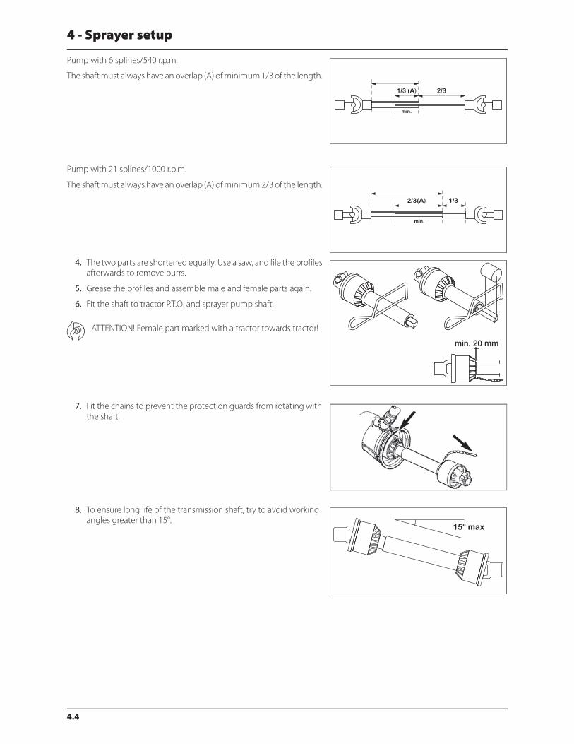
Pump with 6 splines/540 r.p.m.
The shaft must always have an overlap (A) of minimum 1/3 of the length.
Pump with 21 splines/1000 r.p.m.
The shaft must always have an overlap (A) of minimum 2/3 of the length.
4. The two parts are shortened equally. Use a saw, and file the profiles
afterwards to remove burrs.
5. Grease the profiles and assemble male and female parts again.
6. Fit the shaft to tractor P.T.O. and sprayer pump shaft.
ATTENTION! Female part marked with a tractor towards tractor!
7. Fit the chains to prevent the protection guards from rotating with
the shaft.
8. To ensure long life of the transmission shaft, try to avoid working
angles greater than 15°.
4 - Sprayer setup
4.5
Mechanical connections
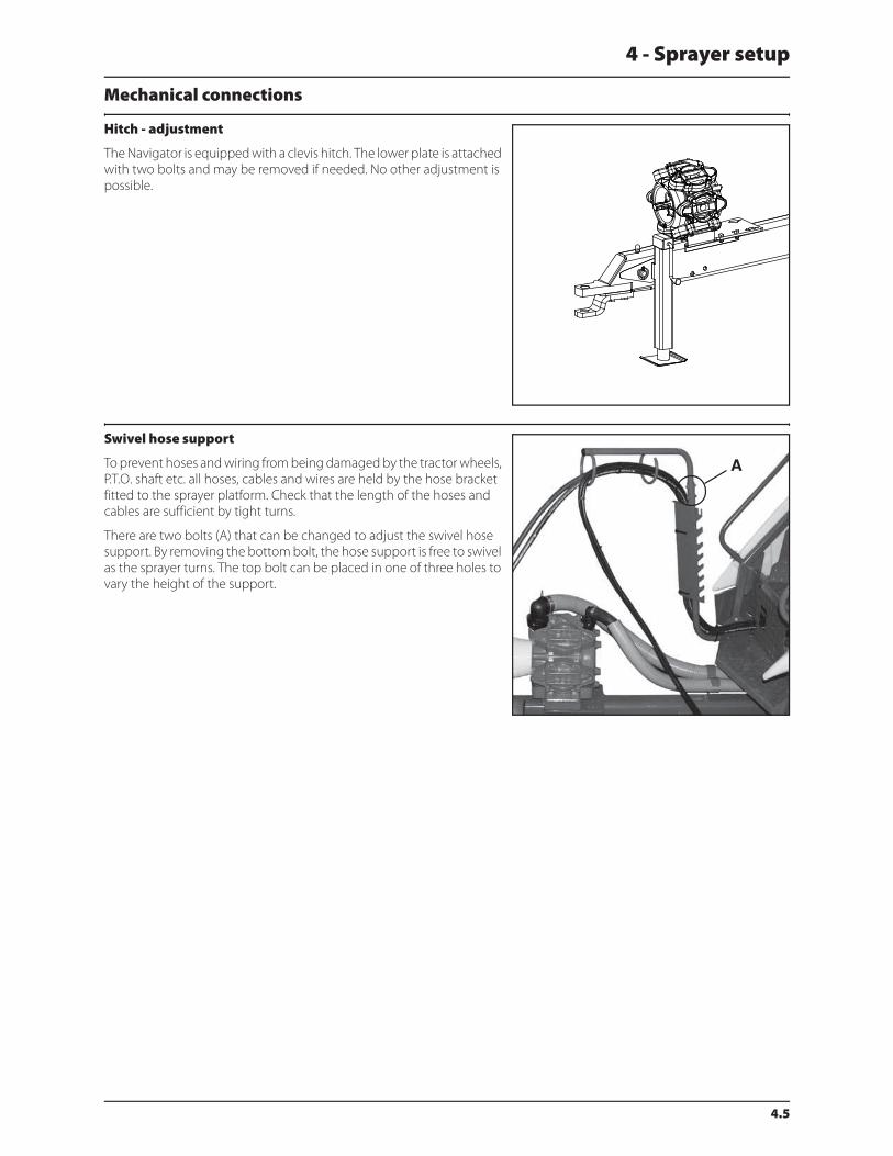
Hitch - adjustment
The Navigator is equipped with a clevis hitch. The lower plate is attached
with two bolts and may be removed if needed. No other adjustment is
possible.
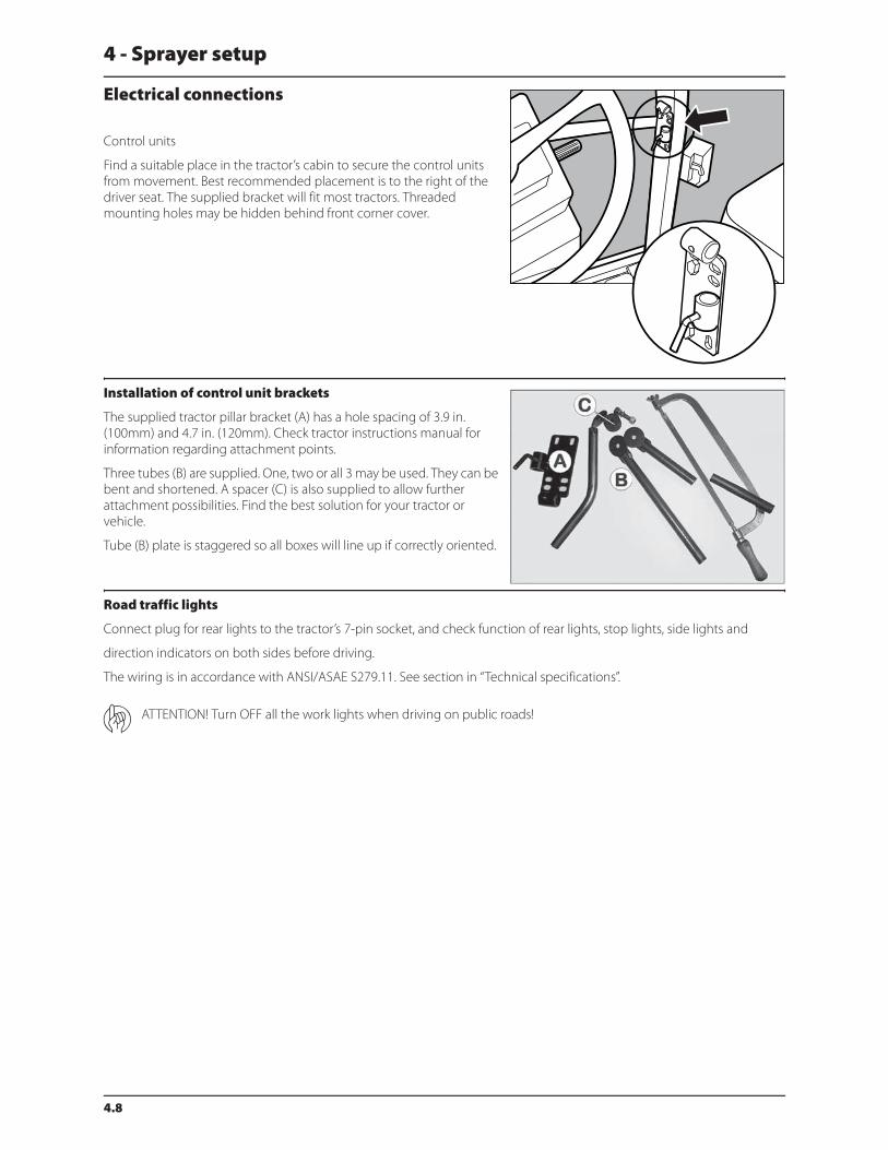
Swivel hose support
To prevent hoses and wiring from being damaged by the tractor wheels,
P.T.O. shaft etc. all hoses, cables and wires are held by the hose bracket
fitted to the sprayer platform. Check that the length of the hoses and
cables are sufficient by tight turns.
There are two bolts (A) that can be changed to adjust the swivel hose
support. By removing the bottom bolt, the hose support is free to swivel
as the sprayer turns. The top bolt can be placed in one of three holes to
vary the height of the support.
A

4 - Sprayer setup
4.6
Hydraulic systems
General info
Ensure that snap couplers are clean before connection!
After having operated the boom and the system has been filled with oil, check tractor’s hydraulic oil level and add oil if
necessary.
€ DANGER! Test of the hydraulic system should be done very cautiously. There may be air trapped in the system which
can cause violent movements of the boom.
€ DANGER! Hydraulic leaks: Never use your fingers to locate a leakage in any part of the hydraulic system. Due to high
pressure, hydraulic oil may penetrate the skin.
Requirements - tractor (SPB/SPC HY-model)
Connection requirements are:
• One single acting outlet for the lift function of the spray boom.
• One double acting outlet for the folding function.
Ensure that snap couplers are clean before connection!
The hydraulic system requires a minimum oil pressure of 2,175 p.s.i. (150 bar), max. oil pressure of 3,050 p.s.i. (210 bar) and
an oil capacity of approx. 6.6 gal (25 liters).
ATTENTION! After having operated the boom and the system has been filled with oil, then check tractor’s hydraulic
oil level and add oil if necessary.
± WARNING! Due to the variation in tractor hydraulic systems and capacities, care should be exercised when initially
operating the sprayer hydraulic cylinders. It is advisable to adjust the hydraulic flow control down to the minimum
rate before operating the system. Adjust/increase the flow control after the system is bled of any air, if necessary.
Requirements - tractor (SPB/SPC HZ-model)
The hydraulic system requires a double acting hydraulic outlet. The hydraulic hoses are marked with arrows to indicate
direction of oil flow.
The hydraulic system requires an oil flow between 6.6 - 34.3 gal/min. (25 and 130 l/min) and a min. pressure of 2500 p.s.i.
(170 bar).

4 - Sprayer setup
4.7
Open center hydraulics (optional equipment)
The open center hydraulics block is needed if the tractor uses open
center hydraulics and/or if load sensing will be used.
The valve (1) on the side of the block is factory set for open center
hydraulics, but if closed center hydraulics will be used (also in
combination with load sensing) then screw in the valve.
Certain tractor models are able to use Load Sensing without connecting
an external sensing line. But if optimal sensing control pressure cannot
be obtained, an external sensing line needs to be mounted (3). Please
consult your tractor dealer for correct setup and correct connection.
Before operating the hydraulics, the valve should be adjusted according
to the specific tractor model. If you have doubt about which type of
hydraulic system your tractor is equipped with, please consult your
tractor dealer.
List of setting combinations for flow element and circuit value:
Valve no. 1 2 3 (LS port)
Open center out out Not conn.
Closed center in in Not conn.
Load sensing (LS) in out* Connected
*if tractor requires pressure relief.
± WARNING! Always be sure to fully extract or retract the open/closed center selection valve (1). Failure to do so can
result in damages to vital pump parts.
± WARNING! It is of essential importance that connectors on sensing line are kept totally clean. Failure to do so can
result in impurities entering the pump and thereby cause damages to vital pump parts.
4 - Sprayer setup
4.8
Electrical connections
Control units
Find a suitable place in the tractor’s cabin to secure the control units
from movement. Best recommended placement is to the right of the
driver seat. The supplied bracket will fit most tractors. Threaded
mounting holes may be hidden behind front corner cover.
Installation of control unit brackets
The supplied tractor pillar bracket (A) has a hole spacing of 3.9 in.
(100mm) and 4.7 in. (120mm). Check tractor instructions manual for
information regarding attachment points.
Three tubes (B) are supplied. One, two or all 3 may be used. They can be
bent and shortened. A spacer (C) is also supplied to allow further
attachment possibilities. Find the best solution for your tractor or
vehicle.
Tube (B) plate is staggered so all boxes will line up if correctly oriented.
Road traffic lights
Connect plug for rear lights to the tractor’s 7-pin socket, and check function of rear lights, stop lights, side lights and
direction indicators on both sides before driving.
The wiring is in accordance with ANSI/ASAE S279.11. See section in “Technical specifications”.
ATTENTION! Turn OFF all the work lights when driving on public roads!
4 - Sprayer setup
4.9
Power supply
Power requirement is 12V DC. Always note polarity!
Brown wire is positive (+)
Blue wire is negative (-)
For proper function of the electric equipment, the wires must have the
following gauge ratings and correct fuses to ensure a sufficient power
supply. The supplied power connectors follow the standard of most
newer tractors. If using a tractor with another power connector it is
necessary to disassemble connector and fit it to the existing connector.
The number and kind of connectors can vary on a specific sprayer,
depending on its equipment.
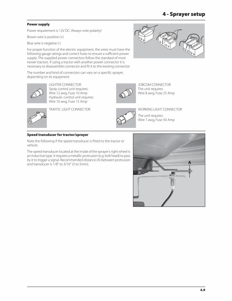
Speed transducer for tractor/sprayer
Note the following if the speed transducer is fitted to the tractor or
vehicle.
The speed transducer located at the inside of the sprayer’s right wheel is
an inductive type. It requires a metallic protrusion (e.g. bolt head) to pass
by it to trigger a signal. Recommended distance (A) between protrusion
and transducer is 1/8” to 3/16” (3 to 5mm).
LIGHTER CONNECTOR
Spray control unit requires:
Wire 12 awg, Fuse 10 Amp
Hydraulic control unit requires:
Wire 10 awg, Fuse 15 Amp
JOBCOM CONNECTOR
The unit requires:
Wire 8 awg, Fuse 25 Amp
TRAFFIC LIGHT CONNECTOR WORKING LIGHT CONNECTOR
The unit requires:
Wire 7 awg, Fuse 30 Amp

4 - Sprayer setup
4.10
Liquid system
CycloneFilter
Standard filter size is 80 mesh. Filters of 50 and 100 mesh are available
and can be changed by opening the filter top. Check condition of O-
rings and lubricate if necessary or replace if damaged before reassembly.
€ DANGER! Never open the Cyclone filter unless the pressure
SmartValve and suction valve are both closed (turned to the
unused position)! Otherwise spraying liquid could hit you when
opening the filter and drain the main tank contents!
Pulsation damper (if fitted)
The air pressure in the pulsation damper is factory preset at 30 p.s.i. (2
bar) to cover spray working pressures between 45 p.s.i. (3 bar) and 225
p.s.i. (15 bar).
When using spray pressures outside this range, the air pressure should
be adjusted as shown in the diagram. The diagram is embossed on the
damper.
Spray pressure Damper pressure
PSI (Bar) PSI (Bar)
20 - 45 (1.5 - 3) 0 - 15 (0 - 1)
45 -225 (3 - 15) 15 - 45 (1 - 3)
225 - 350 (15 - 25) 45 - 60 (3 - 4)
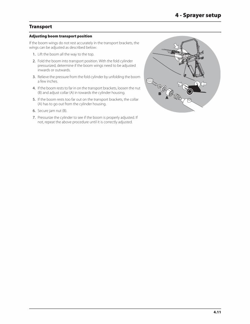
4 - Sprayer setup
4.11
Transport
Adjusting boom transport position
If the boom wings do not rest accurately in the transport brackets, the
wings can be adjusted as described below:
1. Lift the boom all the way to the top.
2. Fold the boom into transport position. With the fold cylinder
pressurized, determine if the boom wings need to be adjusted
inwards or outwards.
3. Relieve the pressure from the fold cylinder by unfolding the boom
a few inches.
4. If the boom rests to far in on the transport brackets, loosen the nut
(B) and adjust collar (A) in towards the cylinder housing.
5. If the boom rests too far out on the transport brackets, the collar
(A) has to go out from the cylinder housing.
6. Secure jam nut (B).
7. Pressurize the cylinder to see if the boom is properly adjusted. If
not, repeat the above procedure until it is correctly adjusted.
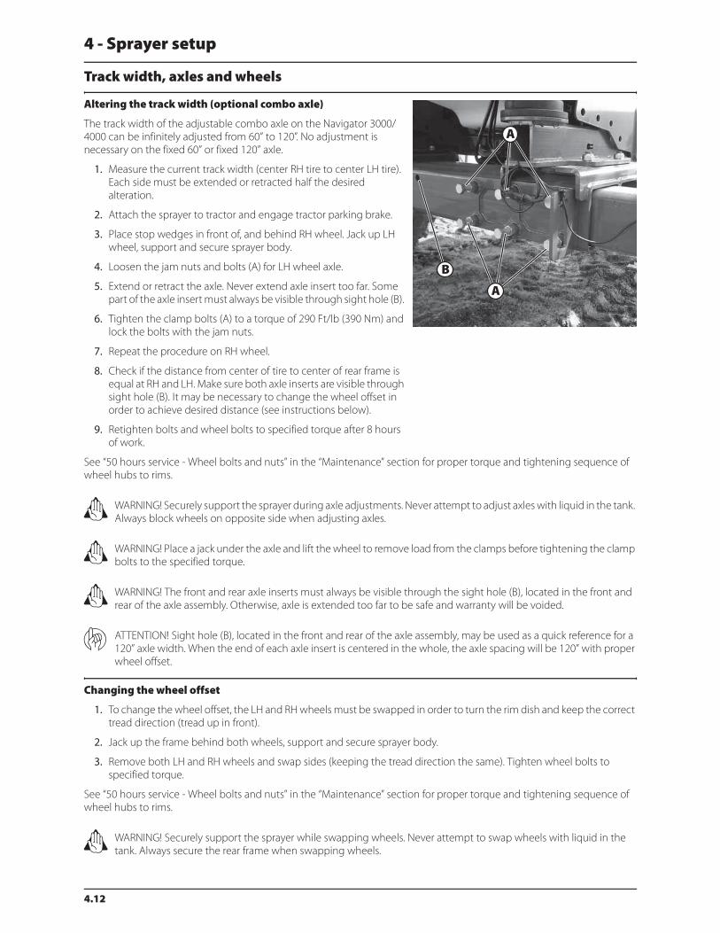
4 - Sprayer setup
4.12
Track width, axles and wheels
Altering the track width (optional combo axle)
The track width of the adjustable combo axle on the Navigator 3000/
4000 can be infinitely adjusted from 60” to 120”. No adjustment is
necessary on the fixed 60” or fixed 120” axle.
1. Measure the current track width (center RH tire to center LH tire).
Each side must be extended or retracted half the desired
alteration.
2. Attach the sprayer to tractor and engage tractor parking brake.
3. Place stop wedges in front of, and behind RH wheel. Jack up LH
wheel, support and secure sprayer body.
4. Loosen the jam nuts and bolts (A) for LH wheel axle.
5. Extend or retract the axle. Never extend axle insert too far. Some
part of the axle insert must always be visible through sight hole (B).
6. Tighten the clamp bolts (A) to a torque of 290 Ft/lb (390 Nm) and
lock the bolts with the jam nuts.
7. Repeat the procedure on RH wheel.
8. Check if the distance from center of tire to center of rear frame is
equal at RH and LH. Make sure both axle inserts are visible through
sight hole (B). It may be necessary to change the wheel offset in
order to achieve desired distance (see instructions below).
9. Retighten bolts and wheel bolts to specified torque after 8 hours
of work.
See “50 hours service - Wheel bolts and nuts” in the “Maintenance” section for proper torque and tightening sequence of
wheel hubs to rims.
± WARNING! Securely support the sprayer during axle adjustments. Never attempt to adjust axles with liquid in the tank.
Always block wheels on opposite side when adjusting axles.
± WARNING! Place a jack under the axle and lift the wheel to remove load from the clamps before tightening the clamp
bolts to the specified torque.
± WARNING! The front and rear axle inserts must always be visible through the sight hole (B), located in the front and
rear of the axle assembly. Otherwise, axle is extended too far to be safe and warranty will be voided.
ATTENTION! Sight hole (B), located in the front and rear of the axle assembly, may be used as a quick reference for a
120” axle width. When the end of each axle insert is centered in the whole, the axle spacing will be 120” with proper
wheel offset.
Changing the wheel offset
1. To change the wheel offset, the LH and RH wheels must be swapped in order to turn the rim dish and keep the correct
tread direction (tread up in front).
2. Jack up the frame behind both wheels, support and secure sprayer body.
3. Remove both LH and RH wheels and swap sides (keeping the tread direction the same). Tighten wheel bolts to
specified torque.
See “50 hours service - Wheel bolts and nuts” in the “Maintenance” section for proper torque and tightening sequence of
wheel hubs to rims.
± WARNING! Securely support the sprayer while swapping wheels. Never attempt to swap wheels with liquid in the
tank. Always secure the rear frame when swapping wheels.
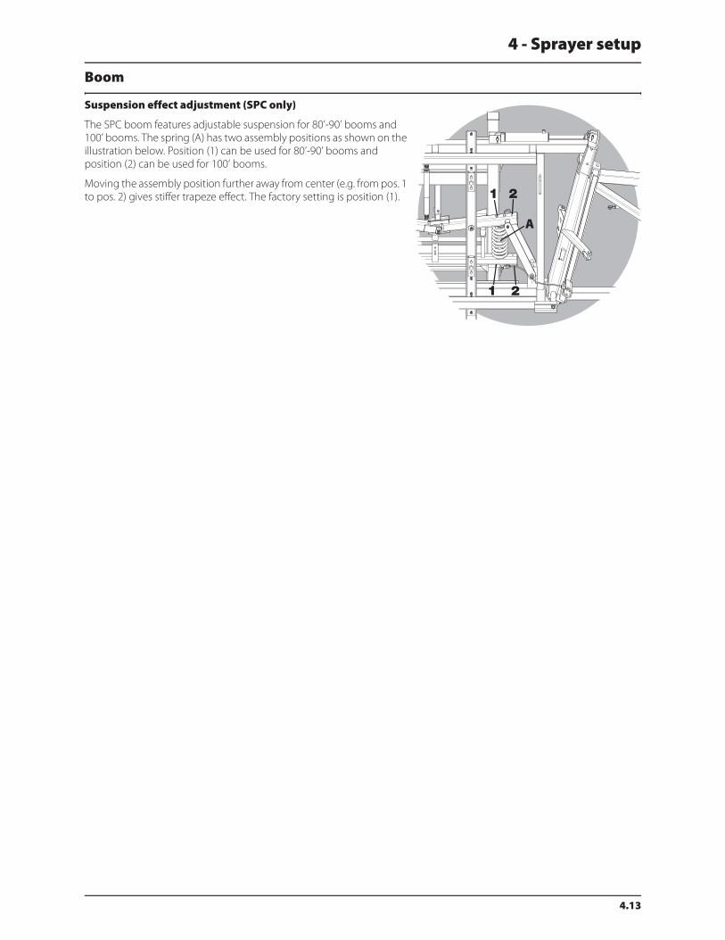
4 - Sprayer setup
4.13
Boom
Suspension effect adjustment (SPC only)
The SPC boom features adjustable suspension for 80’-90’ booms and
100’ booms. The spring (A) has two assembly positions as shown on the
illustration below. Position (1) can be used for 80’-90’ booms and
position (2) can be used for 100’ booms.
Moving the assembly position further away from center (e.g. from pos. 1
to pos. 2) gives stiffer trapeze effect. The factory setting is position (1).

4 - Sprayer setup
4.14
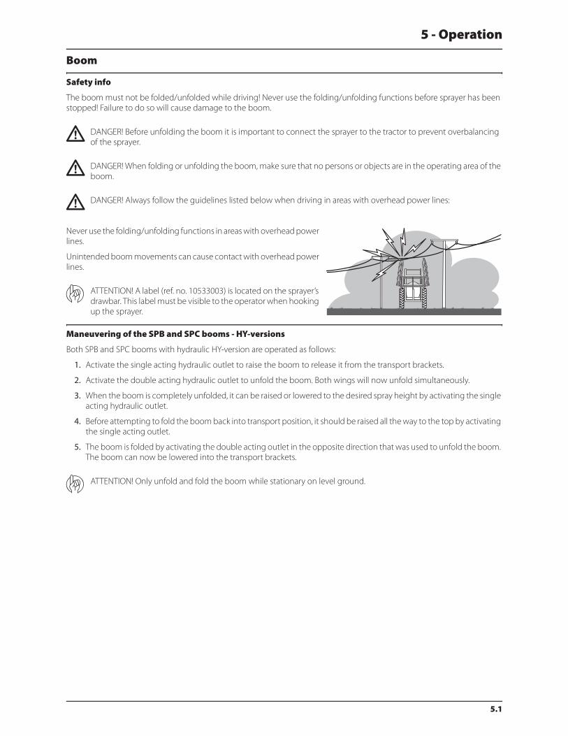
5.1
5 - Operation
Boom
Safety info
The boom must not be folded/unfolded while driving! Never use the folding/unfolding functions before sprayer has been
stopped! Failure to do so will cause damage to the boom.
€ DANGER! Before unfolding the boom it is important to connect the sprayer to the tractor to prevent overbalancing
of the sprayer.
€ DANGER! When folding or unfolding the boom, make sure that no persons or objects are in the operating area of the
boom.
€ DANGER! Always follow the guidelines listed below when driving in areas with overhead power lines:
Never use the folding/unfolding functions in areas with overhead power
lines.
Unintended boom movements can cause contact with overhead power
lines.
ATTENTION! A label (ref. no. 10533003) is located on the sprayer’s
drawbar. This label must be visible to the operator when hooking
up the sprayer.
Maneuvering of the SPB and SPC booms - HY-versions
Both SPB and SPC booms with hydraulic HY-version are operated as follows:
1. Activate the single acting hydraulic outlet to raise the boom to release it from the transport brackets.
2. Activate the double acting hydraulic outlet to unfold the boom. Both wings will now unfold simultaneously.
3. When the boom is completely unfolded, it can be raised or lowered to the desired spray height by activating the single
acting hydraulic outlet.
4. Before attempting to fold the boom back into transport position, it should be raised all the way to the top by activating
the single acting outlet.
5. The boom is folded by activating the double acting outlet in the opposite direction that was used to unfold the boom.
The boom can now be lowered into the transport brackets.
ATTENTION! Only unfold and fold the boom while stationary on level ground.
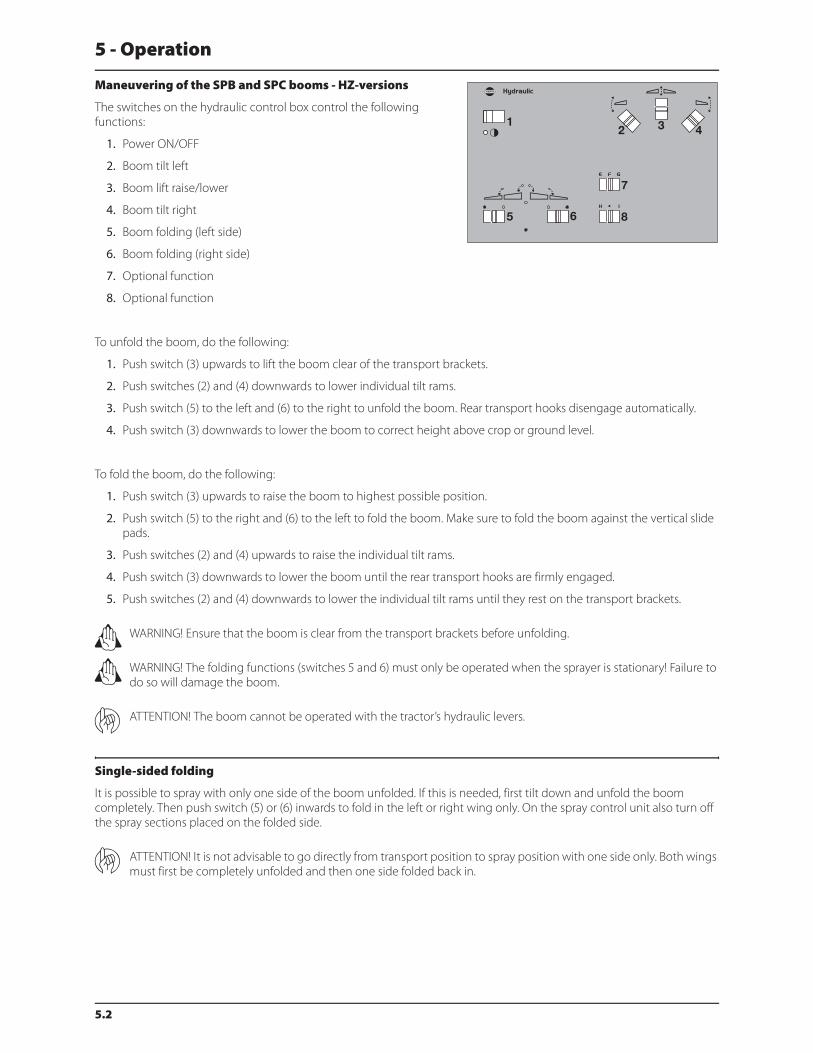
5 - Operation
5.2
Maneuvering of the SPB and SPC booms - HZ-versions
The switches on the hydraulic control box control the following
functions:
1. Power ON/OFF
2. Boom tilt left
3. Boom lift raise/lower
4. Boom tilt right
5. Boom folding (left side)
6. Boom folding (right side)
7. Optional function
8. Optional function
To unfold the boom, do the following:
1. Push switch (3) upwards to lift the boom clear of the transport brackets.
2. Push switches (2) and (4) downwards to lower individual tilt rams.
3. Push switch (5) to the left and (6) to the right to unfold the boom. Rear transport hooks disengage automatically.
4. Push switch (3) downwards to lower the boom to correct height above crop or ground level.
To fold the boom, do the following:
1. Push switch (3) upwards to raise the boom to highest possible position.
2. Push switch (5) to the right and (6) to the left to fold the boom. Make sure to fold the boom against the vertical slide
pads.
3. Push switches (2) and (4) upwards to raise the individual tilt rams.
4. Push switch (3) downwards to lower the boom until the rear transport hooks are firmly engaged.
5. Push switches (2) and (4) downwards to lower the individual tilt rams until they rest on the transport brackets.
± WARNING! Ensure that the boom is clear from the transport brackets before unfolding.
± WARNING! The folding functions (switches 5 and 6) must only be operated when the sprayer is stationary! Failure to
do so will damage the boom.
ATTENTION! The boom cannot be operated with the tractor’s hydraulic levers.
Single-sided folding
It is possible to spray with only one side of the boom unfolded. If this is needed, first tilt down and unfold the boom
completely. Then push switch (5) or (6) inwards to fold in the left or right wing only. On the spray control unit also turn off
the spray sections placed on the folded side.
ATTENTION! It is not advisable to go directly from transport position to spray position with one side only. Both wings
must first be completely unfolded and then one side folded back in.

5 - Operation
5.3
Liquid system
Filling of water
Tank should normally be filled 1/3 with water before adding chemicals.
Always follow instructions given on the chemical container!
± WARNING! If the sprayer is put aside with liquid in the main tank all MANIFOLD valves must be closed.
Filling through tank lid
Water is filled into the tank by removing the tank lid located at front of
sprayer tank which is accessible from platform. It is recommended to use
water as clean as possible for spraying purposes. Always fill water
through the strainer basket to prevent foreign particles from entering
the tank. An overhead tank can be used in order to obtain high filling
capacity.
± WARNING! Do not let the filling hose enter the tank. Keep it outside the tank, pointing towards the filling hole. If the
hose is lowered into the tank and the water pressure drops at the water supply plant, chemicals may be siphoned
back and contaminate the water supply lines and source.
Filling of main tank using Quick fill (optional equipment)
The Quick Filling Device is operated as follows:
1. Remove plug from Quick Fill valve and connect filling hose from
water supply.
2. Turn the main tank Quick Fill valve to “Quick Fill from external tank”
label and fill tank to desired level.
3. Keep an eye on the main tank level indicator.
4. Close the main tank Quick Fill valve (vertical position) and remove
the filling hose.
5. Replace the plug to the Quick Fill coupler when filling is complete.
ATTENTION! Observe local legislation regarding use of filling device. In some areas it is prohibited to fill from open
water reservoirs (lakes, rivers etc.). It is recommended only to fill from closed reservoirs (mobile water tanks etc.) to
avoid contamination.
± WARNING! Do not leave the sprayer while filling the tank. Keep an eye on the level indicator in order NOT to overfill
the tank.
± WARNING! If filling hose/filter is carried on the sprayer during spraying, it can be contaminated by spray drift which
will be transferred to water source when filling!

5 - Operation
5.4
Filling of flush tank using Quick fill (optional equipment)
A flush tank is integrated into the rear of the sprayer and is filled via the
flush tank quick coupler located near the EasyClean filter.
1. Remove plug from Quick Fill coupler and connect filling hose from
water supply.
2. Fill flush tank to desired level.
3. Keep an eye on the flush tank level indicator located on the
platform behind the main tank level indicator.
4. Stop filling and remove the filling hose.
5. Replace the plug to the Quick Fill coupler when filling is complete.
Capacity: 130 gal. (500 liters).
Only fill flush tank with clean water! To avoid algae developing in the
flush tank, always drain the flush tank if the sprayer is not in use for a
longer period of time.
For cleaning purposes etc. the flush tank is also accessible via the tank lid
on top of the tank.
ATTENTION! Observe local legislation regarding use of filling device. In some areas it is prohibited to fill from open
water reservoirs (lakes, rivers etc.). It is recommended only to fill from closed reservoirs (mobile water tanks etc.) to
avoid contamination.
± WARNING! Do not leave the sprayer while filling the tank. Keep an eye on the level indicator in order NOT to overfill
the tank.
± WARNING! If filling hose/filter is carried on the sprayer during spraying, it can be contaminated by spray drift which
will be transferred to water source when filling!
Filling of clean water tank
To fill the clean water tank, remove tank lid. Then fill with clean water and
reposition tank lid.
For use of water, turn the ball valve lever to open tap. The ball valve is
located on the valve cover below the EasyClean filter on sprayer’s left
side. The water from this tank is for hand washing, cleaning of clogged
nozzles, etc. Only fill the clean water tank with clean water.
± WARNING! Although the clean water tank is only filled with clean
water, this water must never be used for drinking.

5 - Operation
5.5
Adjustment of EVC operating unit
Before spraying, the EVC operating unit is adjusted using clean water
(without chemicals).
1. Choose the correct nozzle for the spray job by turning the TRIPLET
nozzle bodies. Make sure that all nozzles are the same type and
capacity. See the “Spray Technique” book.
2. The main on/off switch is set to ON at the spray control unit.
3. All distribution valve switches are turned ON at the spray control
unit.
4. The pressure regulation switch on the spray control unit is pressed
down until the emergency handle on the valve stops rotating
(minimum pressure).
5. Put the tractor in neutral and adjust the P.T.O. and thereby the
number of revolutions of the pump corresponding to the
intended travelling speed. Remember the number of revolutions
on the P.T.O. must be kept between 300-600 rpm (pump 540 rpm)
or 650-1100 rpm (pump 1000 rpm).
6. The pressure regulation switch on the spray control unit is pressed
up until the required spray pressure is shown on the pressure
gauge.
Adjustment of pressure equalization is now done for every single
section valve:
1. Close the first section valve on the spray control unit.
2. Turn the adjusting screw for the corresponding valve until the
pressure gauge again shows the same pressure as when all
sections were open.
3. Open the section valve again.
4. Adjust the next section valves in the same way.
ATTENTION! HEREAFTER ADJUSTMENT OF PRESSURE EQUALIZATION WILL ONLY BE NEEDED WHEN:
1. YOU CHANGE TO NOZZLES WITH OTHER CAPACITIES
2. THE NOZZLE OUTPUT INCREASES AS THE NOZZLES WEAR
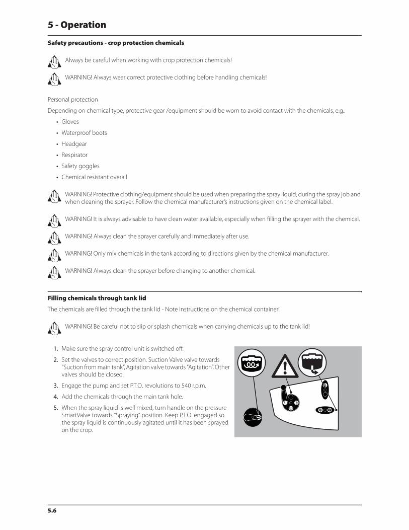
5 - Operation
5.6
Safety precautions - crop protection chemicals
± Always be careful when working with crop protection chemicals!
± WARNING! Always wear correct protective clothing before handling chemicals!
Personal protection
Depending on chemical type, protective gear /equipment should be worn to avoid contact with the chemicals, e.g.:
• Gloves
• Waterproof boots
• Headgear
• Respirator
• Safety goggles
• Chemical resistant overall
± WARNING! Protective clothing/equipment should be used when preparing the spray liquid, during the spray job and
when cleaning the sprayer. Follow the chemical manufacturer’s instructions given on the chemical label.
± WARNING! It is always advisable to have clean water available, especially when filling the sprayer with the chemical.
± WARNING! Always clean the sprayer carefully and immediately after use.
± WARNING! Only mix chemicals in the tank according to directions given by the chemical manufacturer.
± WARNING! Always clean the sprayer before changing to another chemical.
Filling chemicals through tank lid
The chemicals are filled through the tank lid - Note instructions on the chemical container!
± WARNING! Be careful not to slip or splash chemicals when carrying chemicals up to the tank lid!
1. Make sure the spray control unit is switched off.
2. Set the valves to correct position. Suction Valve valve towards
“Suction from main tank”, Agitation valve towards “Agitation”. Other
valves should be closed.
3. Engage the pump and set P.T.O. revolutions to 540 r.p.m.
4. Add the chemicals through the main tank hole.
5. When the spray liquid is well mixed, turn handle on the pressure
SmartValve towards “Spraying” position. Keep P.T.O. engaged so
the spray liquid is continuously agitated until it has been sprayed
on the crop.
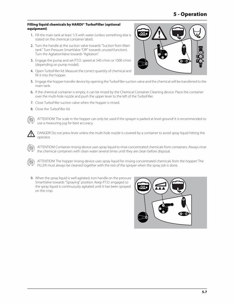
5 - Operation
5.7
Filling liquid chemicals by HARDI® TurboFiller (optional equipment)
1. Fill the main tank at least 1/3 with water (unless something else is
stated on the chemical container label).
2. Turn the handle at the suction valve towards “Suction from Main
tank” Turn Pressure SmartValve “Off” towards unused function).
Turn the AgitationValve towards “Agitation”.
3. Engage the pump and set P.T.O. speed at 540 r/min or 1000 r/min
(depending on pump model).
4. Open TurboFiller lid. Measure the correct quantity of chemical and
fill it into the hopper.
5. Engage the hopper transfer device by opening the TurboFiller suction valve and the chemical will be transferred to the
main tank.
6. If the chemical container is empty, it can be rinsed by the Chemical Container Cleaning device. Place the container
over the multi-hole nozzle and push the upper lever to the left of the TurboFiller.
7. Close TurboFiller suction valve when the hopper is rinsed.
8. Close the TurboFiller lid.
ATTENTION! The scale in the hopper can only be used if the sprayer is parked at level ground! It is recommended to
use a measuring jug for best accuracy.
€ DANGER! Do not press lever unless the multi-hole nozzle is covered by a container to avoid spray liquid hitting the
operator.
ATTENTION! Container rinsing device uses spray liquid to rinse concentrated chemicals from containers. Always rinse
the chemical containers with clean water several times until they are clean before disposal.
ATTENTION! The hopper rinsing device uses spray liquid for rinsing concentrated chemicals from the hopper! The
FILLER must always be cleaned together with the rest of the sprayer when the spray job is done.
9. When the spray liquid is well agitated, turn handle on the pressure
SmartValve towards “Spraying” position. Keep P.T.O. engaged so
the spray liquid is continuously agitated until it has been sprayed
on the crop.
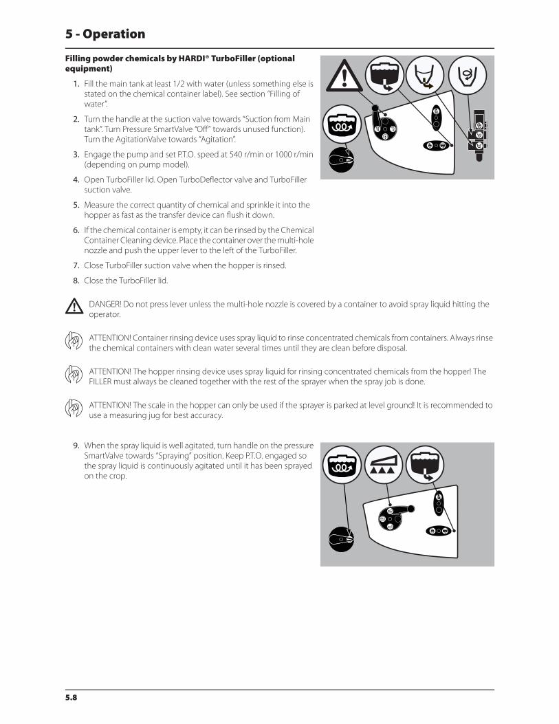
5 - Operation
5.8
Filling powder chemicals by HARDI® TurboFiller (optional equipment)
1. Fill the main tank at least 1/2 with water (unless something else is
stated on the chemical container label). See section “Filling of
water”.
2. Turn the handle at the suction valve towards “Suction from Main
tank”. Turn Pressure SmartValve “Off” towards unused function).
Turn the AgitationValve towards “Agitation”.
3. Engage the pump and set P.T.O. speed at 540 r/min or 1000 r/min
(depending on pump model).
4. Open TurboFiller lid. Open TurboDeflector valve and TurboFiller
suction valve.
5. Measure the correct quantity of chemical and sprinkle it into the
hopper as fast as the transfer device can flush it down.
6. If the chemical container is empty, it can be rinsed by the Chemical
Container Cleaning device. Place the container over the multi-hole
nozzle and push the upper lever to the left of the TurboFiller.
7. Close TurboFiller suction valve when the hopper is rinsed.
8. Close the TurboFiller lid.
€ DANGER! Do not press lever unless the multi-hole nozzle is covered by a container to avoid spray liquid hitting the
operator.
ATTENTION! Container rinsing device uses spray liquid to rinse concentrated chemicals from containers. Always rinse
the chemical containers with clean water several times until they are clean before disposal.
ATTENTION! The hopper rinsing device uses spray liquid for rinsing concentrated chemicals from the hopper! The
FILLER must always be cleaned together with the rest of the sprayer when the spray job is done.
ATTENTION! The scale in the hopper can only be used if the sprayer is parked at level ground! It is recommended to
use a measuring jug for best accuracy.
9. When the spray liquid is well agitated, turn handle on the pressure
SmartValve towards “Spraying” position. Keep P.T.O. engaged so
the spray liquid is continuously agitated until it has been sprayed
on the crop.

5 - Operation
5.9
Operating the control unit while spraying
The switches on the spray control unit control the following functions:
1. Power ON/OFF
2. Spray pressure regulation
3. Main valve ON/OFF
4. Optional function
5. Optional function
6. End nozzle (Left/OFF/Right)
7. Foam marker blob interval
8. Foam marker (Left/OFF/Right)
9. Section valves
In order to close the entire boom, switch main ON/OFF (3) to OFF position. This returns the pump output to the tank through
the return system. The diaphragm Non-drip valves ensure instantaneous closing of all nozzles.
In order to close one or more sections of the boom, switch the relevant distribution valve (9) to off position (A). The pressure
equalization ensures that the pressure does not rise in the sections which are to remain open (B).
On the sprayer, the suction valve should be turned toward “Suction from Main tank” and pressure SmartValve should be
turned toward “Spraying”. Turn the agitation valve to “Agitation” if necessary.
Agitation before re-starting spraying
If a spraying job has been interrupted for a while, severe sedimentation
can occur depending on chemicals being used. When re-starting spray
job it might be necessary to agitate sedimented material first.
1. Turn the handle at the suction valve towards “Suction from Main
tank”. Turn Pressure SmartValve “Off” (towards unused function).
Turn the AgitationValve towards “Agitation”.
2. Engage the pump and set P.T.O. speed at 540 r/min or 1000 r/min
(depending on pump model).
3. Agitation has started and should be continued for at least 10
minutes.
4. Once the chemicals are mixed, spraying can resume. Turn pressure
SmartValve towards “Spraying” and start spraying again.

5 - Operation
5.10
TurboFiller rinsing
Rinsing the TurboFiller and chemical containers are done in the
following two ways:
When TurboFiller lid is open: For cleaning empty containers. Put
container over the rotating flushing nozzle in the middle of the
TurboFiller so that the nozzle is inside the container. Press the Chemical
Container Cleaning lever and TurboFiller suction valve at the same time
to activate the flushing nozzle in the middle of the TurboFiller and
empty out the TurboFiller rinsing liquid.
When TurboFiller lid is closed: Use the Chemical Container Cleaning lever to rinse the hopper after filling of chemicals has
ended. Press the Chemical Container Cleaning lever and TurboFiller suction valve at the same time to activate the flushing
nozzle in the middle of the TurboFiller and empty out the TurboFiller rinsing liquid. Do this 3 times and after last flushing,
then open lid to inspect if the TurboFiller is empty. If not, then close lid again and press TurboFiller suction valve until the
TurboFiller is empty.
Quick reference - Operation
In the following diagram, handle positions for different options are described.
*designates an optional function.

5 - Operation
5.11
Cleaning
General info
In order to derive full benefit from the sprayer for many years, the following service and maintenance program should be
followed.
ATTENTION! Always read the individual paragraphs. Read instructions for service/maintenance jobs carefully before
starting on the job. If any portion remains unclear or requires facilities which are not available, then for safety reasons
please leave the job to your HARDI® dealer’s workshop.
ATTENTION!
Clean sprayers are safe sprayers.
Clean sprayers are ready for action.
Clean sprayers cannot be damaged by pesticides and their solvents.
Guidelines
1. Read the whole chemical label. Take note of any particular instructions regarding recommended protective clothing,
deactivating agents, etc. Read the detergent and deactivating agent labels. If cleaning procedures are given, follow
them closely.
2. Be familiar with local legislation regarding disposal of pesticides washings, mandatory decontamination methods, etc.
Contact the appropriate department, e.g. Dept. of Agriculture.
3. Pesticide washings can usually be sprayed out on a soakaway. This is an area of ground that is not used for cropping.
You must avoid seepage or runoff of residue into streams, water courses, ditches, wells, springs, etc. The washings from
the cleaning area must not enter sewers. Drainage must lead to an approved soakaway.
4. Cleaning starts with the calibration, as a well calibrated sprayer will ensure the minimal amount of remaining spray
liquid.
5. It is good practice to clean the sprayer immediately after use and thereby render the sprayer safe and ready for the next
pesticide application. This also prolongs the life of the components.
6. It is sometimes necessary to leave spray liquid in the tank for short periods, e.g. overnight, or until the weather becomes
suitable for spraying again. Unauthorized persons and animals must not have access to the sprayer under these
circumstances.
7. If the product applied is corrosive, it is recommended to coat all metal parts of the sprayer before and after use with a
suitable rust inhibitor.

5 - Operation
5.12
Cleaning the tank and liquid system
1. Dilute remaining spray liquid in the tank with at least 10 parts of water and spray the liquid out in the field you have
just sprayed.
2. Select and use the appropriate protective clothing. Select detergent suitable for cleaning and suitable deactivating
agents if necessary.
3. Rinse and clean sprayer and tractor externally. Use detergent if necessary.
4. Remove tank and suction filters and clean. Be careful not to damage the mesh. Replace suction filter top. Replace filters
when the sprayer is completely clean.
5. With the pump running, rinse the inside of the tank. Remember the tank roof. Rinse and operate all components and
any equipment that has been in contact with the chemical. Before opening the distribution valves and spraying the
liquid out, decide whether this should be done in the field again or on the soakaway.
6. After spraying the liquid out, stop the pump and fill at least 1/5 of the tank with clean water. Note that some chemicals
require the tank to be completely filled. Add appropriate detergent and/or deactivating agent, e.g. washing soda or
Triple ammonia.
7. Start the pump and operate all controls enabling the liquid to come in contact with all the components. Leave the
distribution valves until last. Some detergents and deactivating agents work best if left in the tank for a short period.
Check the label. The Cyclone filter can be flushed by engaging the lever in the bottom to flush position. Stop the pump
and remove the hose. Start the pump for a few seconds to flush filter. Be careful not to lose the restrictor nozzle.
8. Drain the tank and let the pump run dry. Rinse inside of the tank, again letting the pump run dry.
ATTENTION! If the sprayer is equipped with a centrifugal pump, do not run pump dry for longer than 3 seconds.
Otherwise severe damage to the pump will occur.
9. Stop the pump. If the pesticides used have a tendency to block nozzles and filters, remove and clean them
immediately.
10. Replace all the filters and nozzles and store the sprayer. If, from previous experiences, it is noted that the solvents in the
pesticide are particularly aggressive, store the sprayer with the tank lid open.
ATTENTION! It is advisable to increase the forward speed (double if possible) and reduce the pressure to 20 psi (1.5
bar) when spraying diluted remaining liquid in the field just sprayed.
ATTENTION! If a cleaning procedure is given on the chemical label, follow it closely.
ATTENTION! If the sprayer is cleaned with a high pressure cleaner, lubrication of the entire machine is recommended.
Cleaning and maintenance of filters
Clean filters ensure:
• Sprayer components such as valves, diaphragms and operating unit are not hindered or damaged during operation.
• Nozzle blockages do not occur while spraying.
• Long life of the pump. A blocked suction filter will result in pump cavitation. The main filter protecting sprayer
components is the suction filter. Check it regularly.

5 - Operation
5.13
Use of flush tank and rinsing nozzles (optional equipment)
The incorporated flush tank can be used for two different purposes.
A. In-field diluting of remaining spray liquid residue in the spraying circuit for spraying the liquid in the field, before cleaning
the sprayer. This cleaning procedure is divided in three main steps:
Cleaning of the liquid system:
1. Empty the sprayer as much as possible. Close the AgitationValve (no agitation) and spray till air comes out of all nozzles.
2. Turn suction valve towards “Flush tank” and pressure SmartValve towards “Spray” with control unit turned “Off”.
3. Engage and set the pump at approximately 300 r.p.m.
4. When 1/3 of contents in flush tank are used, turn suction valve towards “Main tank” and operate all valves on the
pressure side of the system, so all hoses and components are rinsed. If equipped with HARDI® TurboFiller turn the
pressure SmartValve “Off” (towards unused function) and open TurboFiller suction valve. Open TurboDeflector valve
and close it again when clean water comes out of nozzles. Close TurboFiller lid and squeeze the Chemical Container
Cleaning lever to clean this device. Open TurboFiller lid again and assure that TurboFiller is empty. When empty, close
the TurboFiller suction valve.
5. Turn the suction valve towards “Main tank” and pressure SmartValve towards “Spray”. Open the AgitationValve and
spray liquid in the field you have just sprayed.
Cleaning of Main tank:
6. Turn the suction valve towards “Flush tank” and pressure SmartValve towards “Internal Tank Cleaning”. The filling
strainer should be removed, so there is no cleaning shadow behind the filling strainer.
7. When another 1/6 of content in flush tank are used, then turn suction valve towards “Suction from Main tank”.
8. Turn pressure SmartValve towards “Spray” and spray liquid in the field you have just sprayed.
9. Repeat point 6 - 8 one more time. External cleaning:
10. Turn suction valve towards “Flush tank” and pressure SmartValve towards “Internal Tank Cleaning”.
11. When another 1/3 of contents in flush tank are used, turn suction valve towards “Main tank”.
12. Turn pressure SmartValve towards “External Cleaning Device” and wash the sprayer with the cleaning device located
on sprayer’s right side.
13. Disengage pump again.
± WARNING! When critical chemicals (like sulphonyl urea) have been used or a cleaning adjutant is recommended do
an extra cleaning:
1. Fill the flush tank again.
2. Fill main tank with 130 gal. (500 liters) clean water. See subject “Filling of water” for filling procedure.
3. Add the cleaning chemical to main tank by using the TurboFiller.
4. Clean the whole system again.
5. To get the best cleaning effect, the filter meshes for the EasyClean and the CycloneFilter should be washed with clean
water.
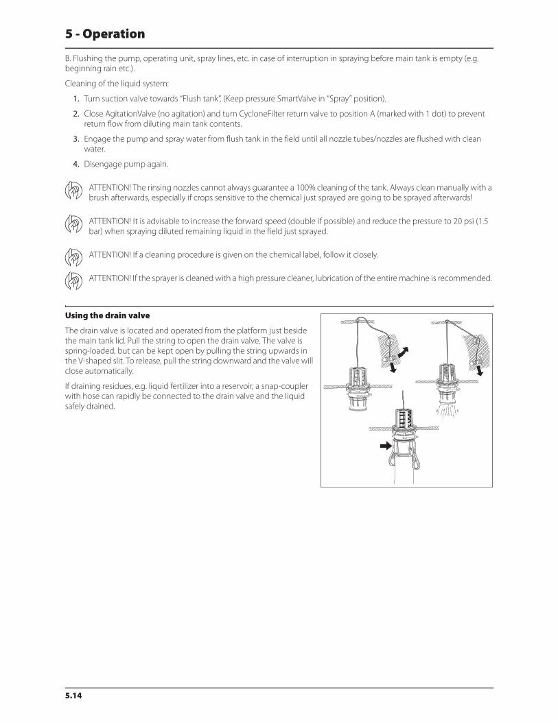
5 - Operation
5.14
B. Flushing the pump, operating unit, spray lines, etc. in case of interruption in spraying before main tank is empty (e.g.
beginning rain etc.).
Cleaning of the liquid system:
1. Turn suction valve towards “Flush tank”. (Keep pressure SmartValve in “Spray” position).
2. Close AgitationValve (no agitation) and turn CycloneFilter return valve to position A (marked with 1 dot) to prevent
return flow from diluting main tank contents.
3. Engage the pump and spray water from flush tank in the field until all nozzle tubes/nozzles are flushed with clean
water.
4. Disengage pump again.
ATTENTION! The rinsing nozzles cannot always guarantee a 100% cleaning of the tank. Always clean manually with a
brush afterwards, especially if crops sensitive to the chemical just sprayed are going to be sprayed afterwards!
ATTENTION! It is advisable to increase the forward speed (double if possible) and reduce the pressure to 20 psi (1.5
bar) when spraying diluted remaining liquid in the field just sprayed.
ATTENTION! If a cleaning procedure is given on the chemical label, follow it closely.
ATTENTION! If the sprayer is cleaned with a high pressure cleaner, lubrication of the entire machine is recommended.
Using the drain valve
The drain valve is located and operated from the platform just beside
the main tank lid. Pull the string to open the drain valve. The valve is
spring-loaded, but can be kept open by pulling the string upwards in
the V-shaped slit. To release, pull the string downward and the valve will
close automatically.
If draining residues, e.g. liquid fertilizer into a reservoir, a snap-coupler
with hose can rapidly be connected to the drain valve and the liquid
safely drained.
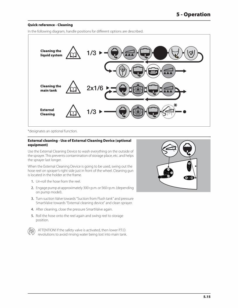
5 - Operation
5.15
Quick reference - Cleaning
In the following diagram, handle positions for different options are described.
*designates an optional function.
External cleaning - Use of External Cleaning Device (optional equipment)
Use the External Cleaning Device to wash everything on the outside of
the sprayer. This prevents contamination of storage place, etc. and helps
the sprayer last longer.
When the External Cleaning Device is going to be used, swing out the
hose reel on sprayer’s right side just in front of the wheel. Cleaning gun
is located in the holder at the frame.
1. Un-roll the hose from the reel.
2. Engage pump at approximately 300 r.p.m. or 560 r.p.m. (depending
on pump model).
3. Turn suction Valve towards “Suction from Flush tank” and pressure
SmartValve towards “External cleaning device” and clean sprayer.
4. After cleaning, close the pressure SmartValve again.
5. Roll the hose onto the reel again and swing reel to storage
position.
ATTENTION! If the safety valve is activated, then lower P.T.O.
revolutions to avoid rinsing water being lost into main tank.
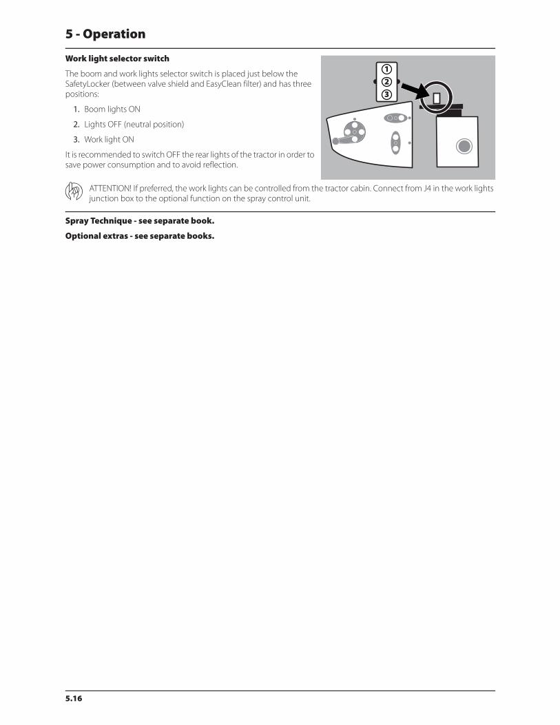
5 - Operation
5.16
Work light selector switch
The boom and work lights selector switch is placed just below the
SafetyLocker (between valve shield and EasyClean filter) and has three
positions:
1. Boom lights ON
2. Lights OFF (neutral position)
3. Work light ON
It is recommended to switch OFF the rear lights of the tractor in order to
save power consumption and to avoid reflection.
ATTENTION! If preferred, the work lights can be controlled from the tractor cabin. Connect from J4 in the work lights
junction box to the optional function on the spray control unit.
Spray Technique - see separate book.
Optional extras - see separate books.

6.1
6 - Maintenance
Lubrication
General info
Always store lubricants clean, dry and cool - preferably at a constant
temperature - to avoid contamination from dirt and condensed water.
Keep oil filling jugs, hoppers and grease guns clean, and clean the
lubricating points thoroughly before lubricating. Avoid skin contact with
oil products for longer periods.
Always follow the shown direction concerning recommended quantity.
If no recommended quantity is given, feed lubricator till new grease
becomes visible.
Pictograms in lubrication & oiling plans tell the following:
1. Lubricant to be used (see “Recommended lubricants”).
2. Operating hours before next lubrication.
ATTENTION! If the sprayer is cleaned with a high pressure cleaner, lubrication of the entire machine is recommended.
Recommended lubricants
Boom lubrication & oiling plan
BALL BEARINGS:
Universal Lithium grease, NLGI No. 2
SHELL RETINAX EP2
CASTROL LMX GREASE
SLIDE BEARINGS:
Lithium grease with
Molybdenumdisulphide or graphite
SHELL RETINAX HD 2 (or HDX 2)
OIL LUB. POINTS:
TOTAL Transmission TM
SAE 80W/90
Castrol EPX 80W/90
SHELL Spirax 80W/90
Mobil Mobilube 80W/90
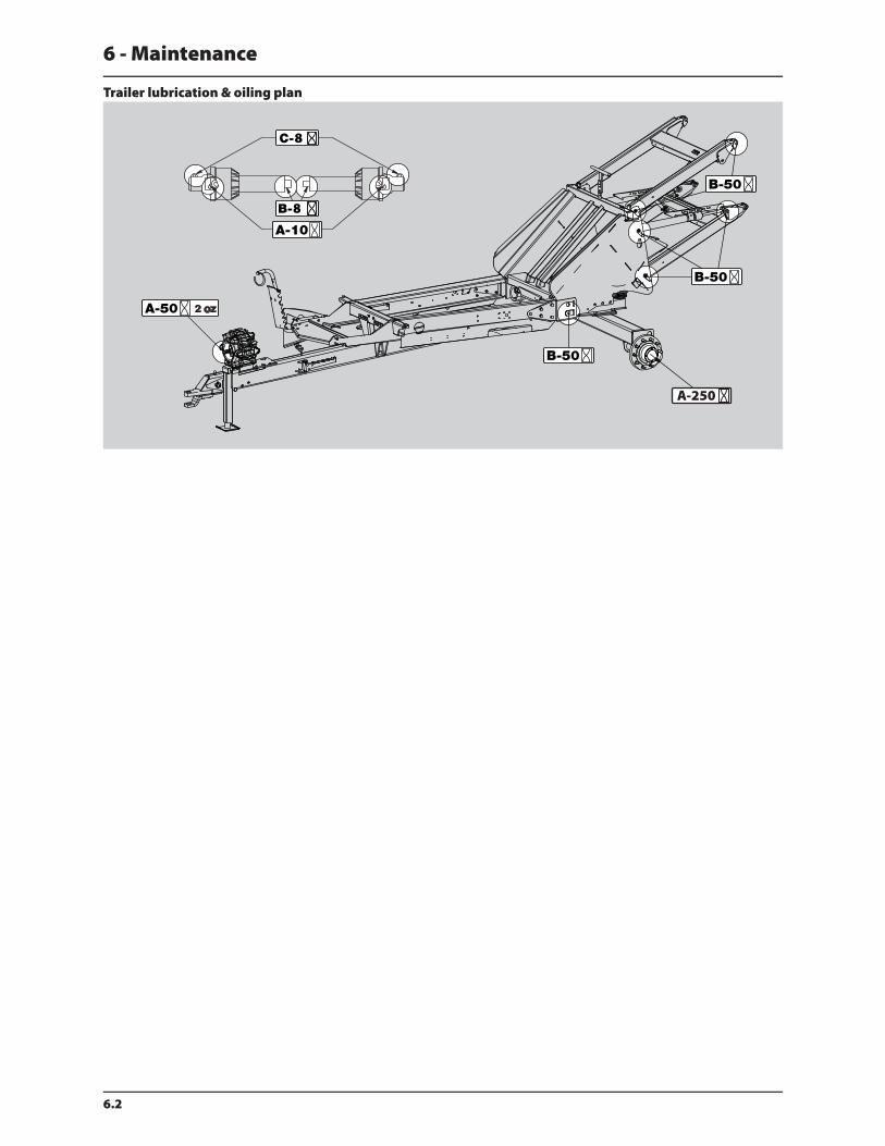
6 - Maintenance
6.2
Trailer lubrication & oiling plan

6 - Maintenance
6.3
Service and Maintenance intervals
10 hours service - Cyclone filter
To service the Cyclone filter:
1. Close the suction valve and turn the pressure SmartValve to “Main
tank” or an unused function.
2. Unscrew filter lid (A).
3. Lift the lid and filter (B) from housing.
4. Separate filter from the integrated filter guide in the lid and clean
the filter.
To reassemble:
1. Grease the two O-rings on the lid/filter guide. Due to small space
at lid, for example, use a brush to grease with.
2. Mount the filter onto the recess (which may not be greased) in the
lid/filter guide.
3. Place the filter/filter lid into housing and screw the lid until it hits
the stop.
€ DANGER! Suction valve must always be closed and the pressure SmartValve to “Main tank” before opening the
Cyclone filter! If not then spraying liquid can hit you when opening the filter and drain the main tank content!
± WARNING! Always wear protective clothing and gloves before opening the filter!
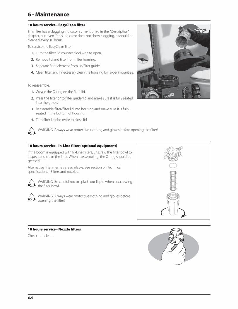
6 - Maintenance
6.4
10 hours service - EasyClean filter
This filter has a clogging indicator as mentioned in the “Description”
chapter, but even if this indicator does not show clogging, it should be
cleaned every 10 hours.
To service the EasyClean filter:
1. Turn the filter lid counter clockwise to open.
2. Remove lid and filter from filter housing.
3. Separate filter element from lid/filter guide.
4. Clean filter and if necessary clean the housing for larger impurities.
To reassemble:
1. Grease the O-ring on the filter lid.
2. Press the filter onto filter guide/lid and make sure it is fully seated
into the guide.
3. Reassemble filter/filter lid into housing and make sure it is fully
seated in the bottom of housing.
4. Turn filter lid clockwise to close lid.
± WARNING! Always wear protective clothing and gloves before opening the filter!
10 hours service - In-Line filter (optional equipment)
If the boom is equipped with In-Line Filters, unscrew the filter bowl to
inspect and clean the filter. When reassembling, the O-ring should be
greased.
Alternative filter meshes are available. See section on Technical
specifications - Filters and nozzles.
± WARNING! Be careful not to splash out liquid when unscrewing
the filter bowl.
± WARNING! Always wear protective clothing and gloves before
opening the filter!
10 hours service - Nozzle filters
Check and clean.
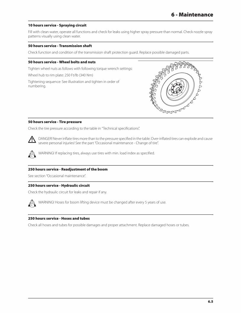
6 - Maintenance
6.5
10 hours service - Spraying circuit
Fill with clean water, operate all functions and check for leaks using higher spray pressure than normal. Check nozzle spray
patterns visually using clean water.
50 hours service - Transmission shaft
Check function and condition of the transmission shaft protection guard. Replace possible damaged parts.
50 hours service - Wheel bolts and nuts
Tighten wheel nuts as follows with following torque wrench settings:
Wheel hub to rim plate: 250 Ft/lb (340 Nm)
Tightening sequence: See illustration and tighten in order of
numbering.
50 hours service - Tire pressure
Check the tire pressure according to the table in “Technical specifications”.
€ DANGER! Never inflate tires more than to the pressure specified in the table. Over-inflated tires can explode and cause
severe personal injuries! See the part “Occasional maintenance - Change of tire”.
± WARNING! If replacing tires, always use tires with min. load index as specified.
250 hours service - Readjustment of the boom
See section “Occasional maintenance”.
250 hours service - Hydraulic circuit
Check the hydraulic circuit for leaks and repair if any.
± WARNING! Hoses for boom lifting device must be changed after every 5 years of use.
250 hours service - Hoses and tubes
Check all hoses and tubes for possible damages and proper attachment. Replace damaged hoses or tubes.

6 - Maintenance
6.6
250 hours service - Wheel bearings
Check for play in the wheel bearings:
1. Place stop wedges in front of and behind LH wheel and jack up RH
wheel.
2. Rock the RH wheel to discover possible play in the bearings.
3. If any play, support the wheel axle to prevent the trailer from falling
down from the jack.
4. Remove hub cap (A) and cotter pin (B). Turn the wheel and tighten
the castle nut (C) until a slight resistance in the wheel rotation is
felt.
5. Loosen the castle nut until the first notch - horizontal or vertical is
aligned with the cotter pin hole in the shaft.
6. Fit a new cotter pin and bend it.
7. Fill the hub cap with fresh grease and screw it on to the hub again.
8. Repeat the procedure on LH wheel.
1000 hours service - Transmission shaft
Change the protection tube nylon bearings as described under “Shield replacement on transmission shaft”.
1000 hours service - Wheel bearings
Check the condition of the bearings in the following way:
1. Place stop wedges in front of and behind LH wheel and jack up RH
wheel.
2. Support the trailer with axle stands.
3. Remove the wheel.
4. Unscrew the 4 Allen bolts and remove the hub cap (A), cotter pin
(B) and castle nut (C).
5. Pull off the wheel hub assembly (D). Use a wheel puller if necessary.
6. Remove roller bearings (E), clean all parts in degreasing detergent
and dry them. Inspect bearings (E) and replace if necessary.
7. Pack bearings (E) with fresh wheel bearing grease and re-install
using a new seal (F).
8. Turn the wheel and tighten the castle nut (C) until a slight
resistance in the wheel rotation is felt.
9. Loosen the castle nut until the first notch (horizontal or vertical) is
aligned with the cotter pin hole on the shaft.
10. Fit a new cotter pin and bend it.
11. Fill the hub cap with fresh grease and re-attach it onto the hub.
12. Repeat the procedure on the LH wheel.
ATTENTION! The shaft has a vertical and an horizontal cotter pin hole. Use the one first aligned with the notch when
loosening the castellated nut.
± WARNING! If you do not feel totally confident changing wheel bearings, contact your HARDI® dealer’s workshop.
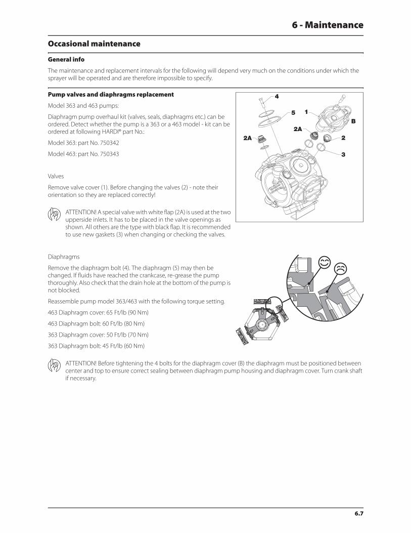
6 - Maintenance
6.7
Occasional maintenance
General info
The maintenance and replacement intervals for the following will depend very much on the conditions under which the
sprayer will be operated and are therefore impossible to specify.
Pump valves and diaphragms replacement
Model 363 and 463 pumps:
Diaphragm pump overhaul kit (valves, seals, diaphragms etc.) can be
ordered. Detect whether the pump is a 363 or a 463 model - kit can be
ordered at following HARDI® part No.:
Model 363: part No. 750342
Model 463: part No. 750343
Valves
Remove valve cover (1). Before changing the valves (2) - note their
orientation so they are replaced correctly!
ATTENTION! A special valve with white flap (2A) is used at the two
upperside inlets. It has to be placed in the valve openings as
shown. All others are the type with black flap. It is recommended
to use new gaskets (3) when changing or checking the valves.
Diaphragms
Remove the diaphragm bolt (4). The diaphragm (5) may then be
changed. If fluids have reached the crankcase, re-grease the pump
thoroughly. Also check that the drain hole at the bottom of the pump is
not blocked.
Reassemble pump model 363/463 with the following torque setting.
463 Diaphragm cover: 65 Ft/lb (90 Nm)
463 Diaphragm bolt: 60 Ft/lb (80 Nm)
363 Diaphragm cover: 50 Ft/lb (70 Nm)
363 Diaphragm bolt: 45 Ft/lb (60 Nm)
ATTENTION! Before tightening the 4 bolts for the diaphragm cover (B) the diaphragm must be positioned between
center and top to ensure correct sealing between diaphragm pump housing and diaphragm cover. Turn crank shaft
if necessary.

6 - Maintenance
6.8
Pump valves and diaphragms replacement
Model 1303 pumps:
Diaphragm pump overhaul kit (valves, seals, diaphragms etc.) can be
ordered. Model 1303: part No. 750658
Valves
Remove valve cover (1). Before changing the valves (2) - note their
orientation so they are replaced correctly! It is recommended to use
new O-rings (3) when changing or checking valves.
Diaphragms
Remove the diaphragm cover (4). Remove the diaphragm bolt. The
diaphragm (5) may then be changed. If fluids have reached the
crankcase, re-grease the pump thoroughly. Also check that the drain
hole at the bottom of the pump is not blocked.
Reassemble with the following torque setting.
Valve cover: 45 Ft/lb (60 Nm)
Diaphragm cover: 50 Ft/lb (70 Nm)
Diaphragm bolt: 45 Ft/lb (60 Nm)
Cone check/replacement for pressure regulation valve
If it becomes difficult to build up sufficient pressure or if pressure
fluctuations occur, it may be necessary to replace cone and cylinder.
1. Remove 4 x screws (A) and remove the housing.
2. Remove 4 x screws (B).
3. Replace cylinder (C) and O-ring (D).
4. Loosen the nut (E), remove and replace the cone (F).
5. Reassemble in reverse order.
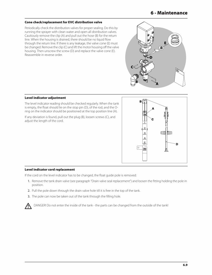
6 - Maintenance
6.9
Cone check/replacement for EVC distribution valve
Periodically check the distribution valves for proper sealing. Do this by
running the sprayer with clean water and open all distribution valves.
Cautiously remove the clip (A) and pull out the hose (B) for the return
line. When the housing is drained, there should be no liquid flow
through the return line. If there is any leakage, the valve cone (E) must
be changed. Remove the clip (C) and lift the motor housing off the valve
housing. Then unscrew the screw (D) and replace the valve cone (E).
Reassemble in reverse order.
Level indicator adjustment
The level indicator reading should be checked regularly. When the tank
is empty, the float should lie on the stop pin (D), of the rod, and the O-
ring on the indicator should be positioned at the top position line (A).
If any deviation is found, pull out the plug (B), loosen screws (C), and
adjust the length of the cord.
Level indicator cord replacement
If the cord on the level indicator has to be changed, the float guide pole is removed:
1. Remove the tank drain valve (see paragraph “Drain valve seal replacement”) and loosen the fitting holding the pole in
position.
2. Pull the pole down through the drain valve hole till it is free in the top of the tank.
3. The pole can now be taken out of the tank through the filling hole.
€ DANGER! Do not enter the inside of the tank - the parts can be changed from the outside of the tank!
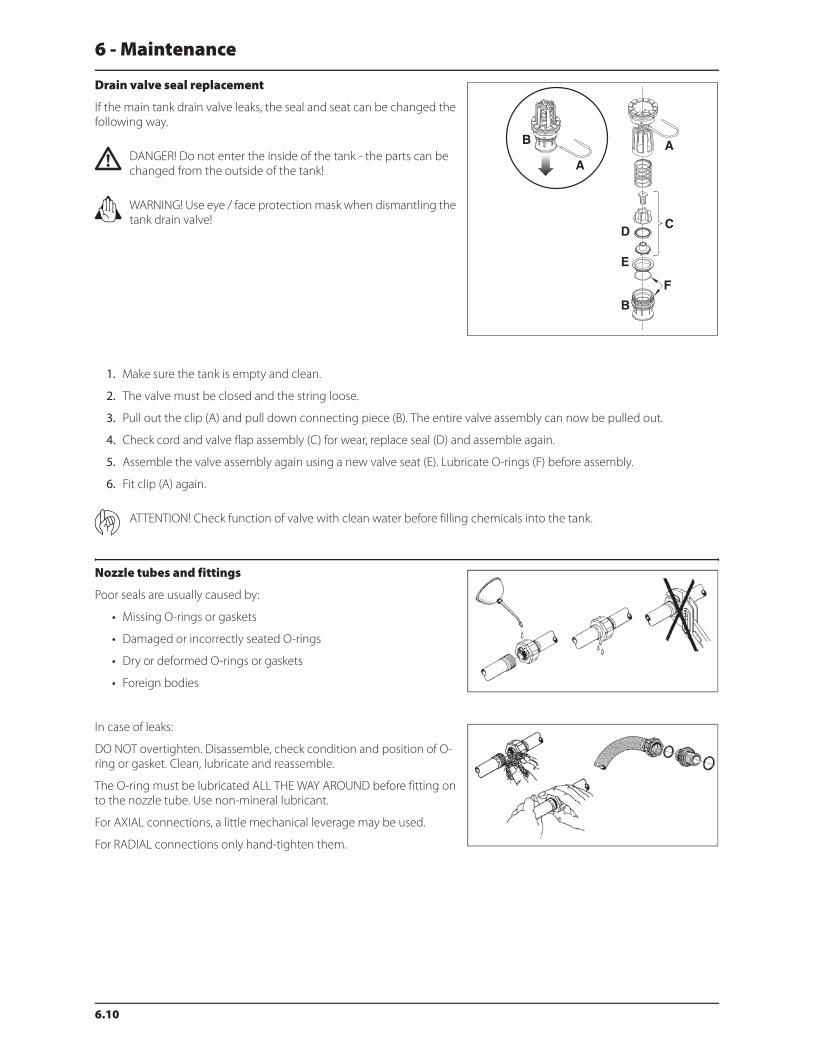
6 - Maintenance
6.10
Drain valve seal replacement
If the main tank drain valve leaks, the seal and seat can be changed the
following way.
€ DANGER! Do not enter the inside of the tank - the parts can be
changed from the outside of the tank!
± WARNING! Use eye / face protection mask when dismantling the
tank drain valve!
1. Make sure the tank is empty and clean.
2. The valve must be closed and the string loose.
3. Pull out the clip (A) and pull down connecting piece (B). The entire valve assembly can now be pulled out.
4. Check cord and valve flap assembly (C) for wear, replace seal (D) and assemble again.
5. Assemble the valve assembly again using a new valve seat (E). Lubricate O-rings (F) before assembly.
6. Fit clip (A) again.
ATTENTION! Check function of valve with clean water before filling chemicals into the tank.
Nozzle tubes and fittings
Poor seals are usually caused by:
• Missing O-rings or gaskets
• Damaged or incorrectly seated O-rings
• Dry or deformed O-rings or gaskets
• Foreign bodies
In case of leaks:
DO NOT overtighten. Disassemble, check condition and position of O-
ring or gasket. Clean, lubricate and reassemble.
The O-ring must be lubricated ALL THE WAY AROUND before fitting on
to the nozzle tube. Use non-mineral lubricant.
For AXIAL connections, a little mechanical leverage may be used.
For RADIAL connections only hand-tighten them.
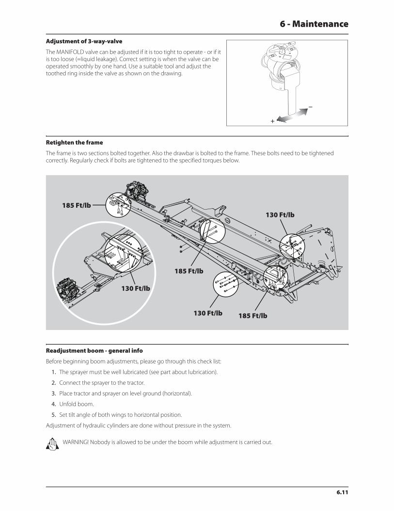
6 - Maintenance
6.11
Adjustment of 3-way-valve
The MANIFOLD valve can be adjusted if it is too tight to operate - or if it
is too loose (=liquid leakage). Correct setting is when the valve can be
operated smoothly by one hand. Use a suitable tool and adjust the
toothed ring inside the valve as shown on the drawing.
Retighten the frame
The frame is two sections bolted together. Also the drawbar is bolted to the frame. These bolts need to be tightened
correctly. Regularly check if bolts are tightened to the specified torques below.
Readjustment boom - general info
Before beginning boom adjustments, please go through this check list:
1. The sprayer must be well lubricated (see part about lubrication).
2. Connect the sprayer to the tractor.
3. Place tractor and sprayer on level ground (horizontal).
4. Unfold boom.
5. Set tilt angle of both wings to horizontal position.
Adjustment of hydraulic cylinders are done without pressure in the system.
± WARNING! Nobody is allowed to be under the boom while adjustment is carried out.
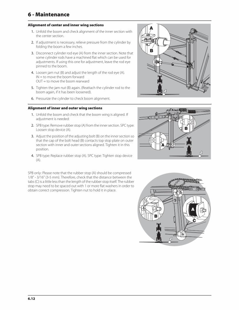
6 - Maintenance
6.12
Alignment of center and inner wing sections
1. Unfold the boom and check alignment of the inner section with
the center section.
2. If adjustment is necessary, relieve pressure from the cylinder by
folding the boom a few inches.
3. Disconnect cylinder rod eye (A) from the inner section. Note that
some cylinder rods have a machined flat which can be used for
adjustments. If using this one for adjustment, leave the rod eye
pinned to the boom.
4. Loosen jam nut (B) and adjust the length of the rod eye (A).
IN = to move the boom forward
OUT = to move the boom rearward
5. Tighten the jam nut (B) again. (Reattach the cylinder rod to the
boom again, if it has been loosened).
6. Pressurize the cylinder to check boom alignment.
Alignment of inner and outer wing sections
1. Unfold the boom and check that the boom wing is aligned. If
adjustment is needed:
2. SPB type: Remove rubber stop (A) from the inner section. SPC type:
Loosen stop device (A).
3. Adjust the position of the adjusting bolt (B) on the inner section so
that the cap of the bolt head (B) contacts top stop plate on outer
section with inner and outer sections aligned. Tighten it in this
position.
4. SPB type: Replace rubber stop (A). SPC type: Tighten stop device
(A).
SPB only: Please note that the rubber stop (A) should be compressed
1/8” - 3/16” (3-5 mm). Therefore, check that the distance between the
tabs (C) is a little less than the length of the rubber stop itself. The rubber
stop may need to be spaced out with 1 or more flat washers in order to
obtain correct compression. Tighten nut to hold it in place.
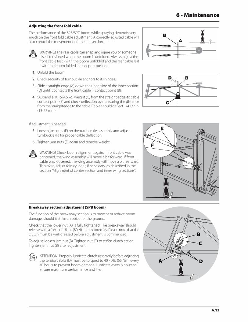
6 - Maintenance
6.13
Adjusting the front fold cable
The performance of the SPB/SPC boom while spraying depends very
much on the front fold cable adjustment. A correctly adjusted cable will
also control the movement of the outer section.
± WARNING! The rear cable can snap and injure you or someone
else if tensioned when the boom is unfolded. Always adjust the
front cable first - with the boom unfolded and the rear cable last
- with the boom folded in transport position.
1. Unfold the boom.
2. Check security of turnbuckle anchors to its hinges.
3. Slide a straight edge (A) down the underside of the inner section
(D) until it contacts the front cable = contact point (B).
4. Suspend a 10 lb (4.5 kg) weight (C) from the straight edge-to cable
contact point (B) and check deflection by measuring the distance
from the straightedge to the cable. Cable should deflect 1/4 1/2 in.
(13-22 mm).
If adjustment is needed:
5. Loosen jam nuts (E) on the turnbuckle assembly and adjust
turnbuckle (F) for proper cable deflection.
6. Tighten jam nuts (E) again and remove weight.
± WARNING! Check boom alignment again. If front cable was
tightened, the wing assembly will move a bit forward. If front
cable was loosened, the wing assembly will move a bit rearward.
Therefore, adjust fold cylinder, if necessary, as described in the
section “Alignment of center section and inner wing sections”.
Breakaway section adjustment (SPB boom)
The function of the breakaway section is to prevent or reduce boom
damage, should it strike an object or the ground.
Check that the lower nut (A) is fully tightened. The breakaway should
release with a force of 18 lbs (80 N) at the extremity. Please note that the
clutch must be well greased before adjustment is commenced.
To adjust, loosen jam nut (B). Tighten nut (C) to stiffen clutch action.
Tighten jam nut (B) after adjustment.
ATTENTION! Properly lubricate clutch assembly before adjusting
the tension. Bolts (D) must be torqued to 40 Ft/lb (55 Nm) every
40 hours to prevent boom damage. Lubricate every 8 hours to
ensure maximum performance and life.

6 - Maintenance
6.14
Breakaway section adjustment (SPC boom)
The function of the breakaway section is to prevent or reduce boom
damage, should it strike an object or the ground.
Adjust the screw (A) until the breakaway will release at a force of 18 lbs
(80 N) at the extremity. Please note that the clutch must be well greased
before adjustment is commenced.
Check/adjust sprocket timing (SPB only)
1. Unfold the boom and stand on its rear side.
2. Check that the pin connection (A) in the timing chain is aligned
with the center line (B) between the sprocket. Note forward driving
direction (C) - adjustment is done at rearside of the boom. (A) is the
7th pin connection on the chain.
3. To adjust timing, loosen turnbuckles on the front and rear cables
until slack.
4. Line up the chain and sprocket as indicated in step 2 above.
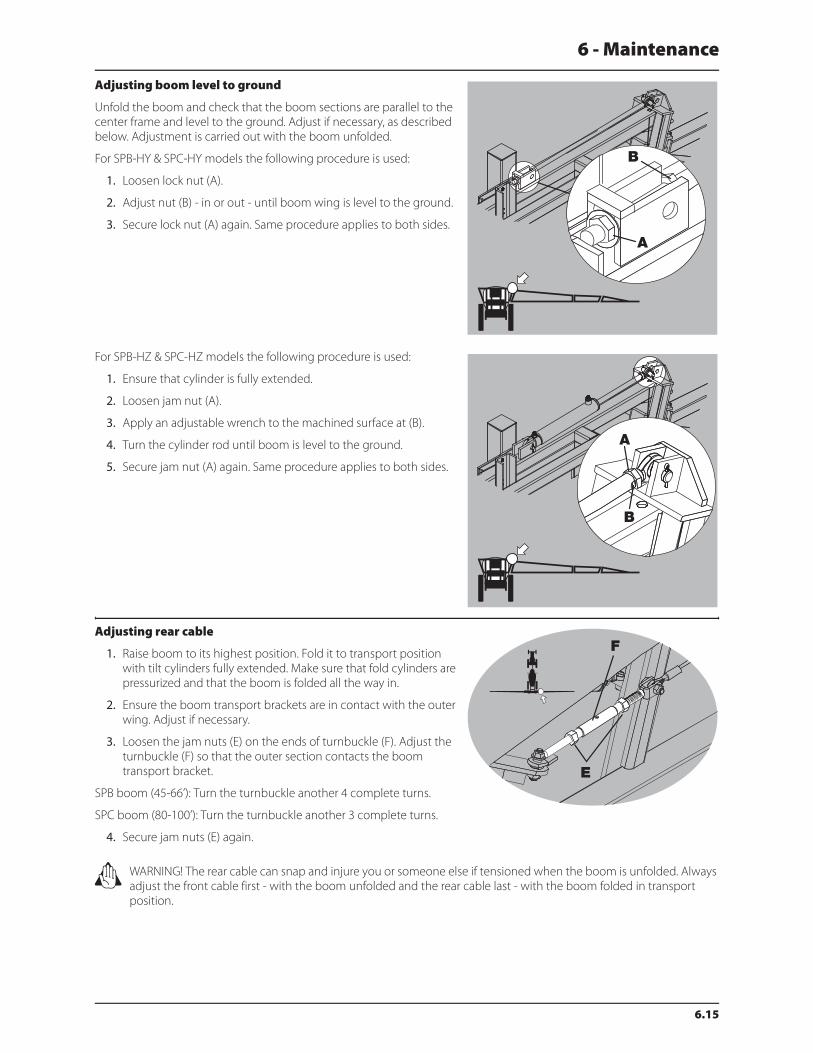
6 - Maintenance
6.15
Adjusting boom level to ground
Unfold the boom and check that the boom sections are parallel to the
center frame and level to the ground. Adjust if necessary, as described
below. Adjustment is carried out with the boom unfolded.
For SPB-HY & SPC-HY models the following procedure is used:
1. Loosen lock nut (A).
2. Adjust nut (B) - in or out - until boom wing is level to the ground.
3. Secure lock nut (A) again. Same procedure applies to both sides.
For SPB-HZ & SPC-HZ models the following procedure is used:
1. Ensure that cylinder is fully extended.
2. Loosen jam nut (A).
3. Apply an adjustable wrench to the machined surface at (B).
4. Turn the cylinder rod until boom is level to the ground.
5. Secure jam nut (A) again. Same procedure applies to both sides.
Adjusting rear cable
1. Raise boom to its highest position. Fold it to transport position
with tilt cylinders fully extended. Make sure that fold cylinders are
pressurized and that the boom is folded all the way in.
2. Ensure the boom transport brackets are in contact with the outer
wing. Adjust if necessary.
3. Loosen the jam nuts (E) on the ends of turnbuckle (F). Adjust the
turnbuckle (F) so that the outer section contacts the boom
transport bracket.
SPB boom (45-66’): Turn the turnbuckle another 4 complete turns.
SPC boom (80-100’): Turn the turnbuckle another 3 complete turns.
4. Secure jam nuts (E) again.
± WARNING! The rear cable can snap and injure you or someone else if tensioned when the boom is unfolded. Always
adjust the front cable first - with the boom unfolded and the rear cable last - with the boom folded in transport
position.
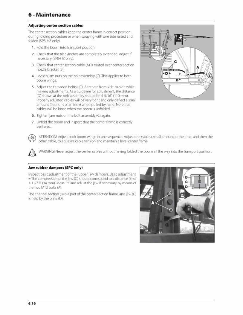
6 - Maintenance
6.16
Adjusting center section cables
The center section cables keep the center frame in correct position
during folding procedure or when spraying with one side raised and
folded (SPB-HZ only).
1. Fold the boom into transport position.
2. Check that the tilt cylinders are completely extended. Adjust if
necessary (SPB-HZ only).
3. Check that center section cable (A) is routed over center section
nozzle bracket (B).
4. Loosen jam nuts on the bolt assembly (C). This applies to both
boom wings.
5. Adjust the threaded bolt(s) (C). Alternate from side-to-side while
making adjustments. As a guideline for adjustment, the distance
(D) shown at the bolt assembly should be 4-5/16” (110 mm).
Properly adjusted cables will be very tight and only deflect a small
amount (fractions of an inch) when pulled by hand. Note that
cables will be loose when the boom is unfolded.
6. Tighten jam nuts on the bolt assembly (C) again.
7. Unfold the boom and inspect that the center frame is correctly
centered.
ATTENTION! Adjust both boom wings in one sequence. Adjust one cable a small amount at the time, and then the
other cable, to equalize cable tension and maintain a level center frame.
± WARNING! Never adjust the center cables without having folded the boom all the way into the transport position.
Jaw rubber dampers (SPC only)
Inspect basic adjustment of the rubber jaw dampers. Basic adjustment
= The compression of the jaw (C) should correspond to a distance (E) of
1-11/32” (34 mm). Measure and adjust the jaw if necessary by means of
the two M12 bolts (A).
The channel section (B) is a part of the center section frame, and jaw (C)
is held by the plate (D).

6 - Maintenance
6.17
Yaw damping
Tighten/loosen bolt (A) to adjust slack at point (B).
If boom does not work smoothly or if it works in ‘steps’: Loosen bolt (A).
If boom works too loosely or swings uncontrollably: Tighten bolt (A).
ATTENTION! Do not overtighten bolt (A). Only tighten till contact
is reached at point (B).
Wear bushing replacement on boom lift
The wear bushings are inspected and replaced before they are worn
through.
1. Connect the trailer to a tractor and unfold the booms to working
position.
2. Lift the boom center frame with a lifting device and support it until
the load is taken off the parallelogram arms.
3. The upper arms must be disconnected simultaneously.
4. Remove the screws (A), and pull out the pins (B) for the upper
parallelogram arms and replace the wear bushings (C).
5. Replace the arms.
6. Repeat this procedure with each of the lower arms.
7. Grease all grease nipples.
8. Remove the lifting gear again.
Change of bulbs
1. Switch off the light.
2. Loosen the screws on the lamp and remove the cover or lens.
3. Remove the bulb.
4. Fit a new bulb, refit the cover and tighten the screws.
ATTENTION! If halogen bulbs are used, never touch the bulb with the fingers. Natural moisture in the skin will cause
the bulb to burn out when the light is switched on. Always use a clean cloth or tissue when handling halogen bulbs.
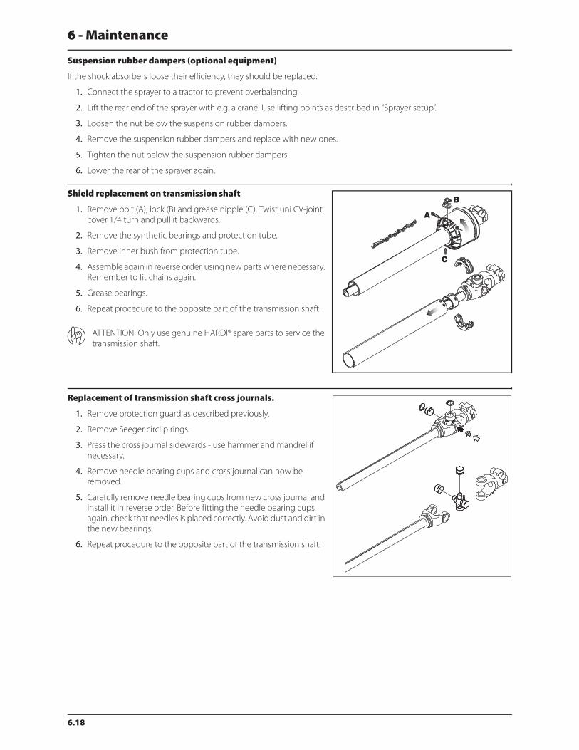
6 - Maintenance
6.18
Suspension rubber dampers (optional equipment)
If the shock absorbers loose their efficiency, they should be replaced.
1. Connect the sprayer to a tractor to prevent overbalancing.
2. Lift the rear end of the sprayer with e.g. a crane. Use lifting points as described in “Sprayer setup”.
3. Loosen the nut below the suspension rubber dampers.
4. Remove the suspension rubber dampers and replace with new ones.
5. Tighten the nut below the suspension rubber dampers.
6. Lower the rear of the sprayer again.
Shield replacement on transmission shaft
1. Remove bolt (A), lock (B) and grease nipple (C). Twist uni CV-joint
cover 1/4 turn and pull it backwards.
2. Remove the synthetic bearings and protection tube.
3. Remove inner bush from protection tube.
4. Assemble again in reverse order, using new parts where necessary.
Remember to fit chains again.
5. Grease bearings.
6. Repeat procedure to the opposite part of the transmission shaft.
ATTENTION! Only use genuine HARDI® spare parts to service the
transmission shaft.
Replacement of transmission shaft cross journals.
1. Remove protection guard as described previously.
2. Remove Seeger circlip rings.
3. Press the cross journal sidewards - use hammer and mandrel if
necessary.
4. Remove needle bearing cups and cross journal can now be
removed.
5. Carefully remove needle bearing cups from new cross journal and
install it in reverse order. Before fitting the needle bearing cups
again, check that needles is placed correctly. Avoid dust and dirt in
the new bearings.
6. Repeat procedure to the opposite part of the transmission shaft.

6 - Maintenance
6.19
Change of tire
Should it be necessary to replace tires, it is recommended to leave this to a specialist and follow the mentioned rules.
1. Always clean and inspect the rim before mounting.
2. Always check that the rim diameter corresponds exactly to the rim diameter molded on the tire.
3. Always inspect inside of the tire for cuts, penetrating objects or other damages. Repairable damages should be
repaired before installing the tube. Tires with unrepairable damages must never be used.
4. Also inspect inside of the tire for dirt or foreign bodies and remove it before installing the tube.
5. Always use tubes of recommended size and in good condition. When fitting new tires always fit new tubes.
6. Before mounting, always lubricate both tire beads and rim flange with approved lubricating agent or equivalent
anticorrosion lubricant. Never use petroleum based greases and oils because they may damage the tire. Using the
appropriate lubricant the tire will never slip on the rim.
7. Always use specialized tools as recommended by the tire supplier for mounting the tires.
8. Make sure that the tire is centered and the beads are perfectly seated on the rim. Otherwise danger of bead wire tear
can occur.
9. Inflate the tire to 15-19 p.s.i. (100-130 kPa) then check whether both beds are seated perfectly on the rim. If any of the
beads do not seat correctly, deflate the assembly and re-center the beads before starting inflation of the tire. If the
beads are seated correctly on the rim at 15-19 p.s.i. (100-130 kPa), inflate the tire to a maximum of 36 p.s.i. (250 kPa) until
they seat perfectly on the rim.
10. Never exceed the maximum mounting pressure molded on the tire!
11. After mounting tires, adjust inflation pressure to operation pressure recommended by the tire manufacturer.
12. Do not use tubes in tubeless tires.
€ DANGER! Non observance of mounting instructions will result in the bad seating of the tire on the rim and could
cause the tire to burst leading to serious injury or death!
€ DANGER! Never mount or use damaged tires or rims! Use of damaged, ruptured, distorted, welded or brazed rim is
not allowed!
Safety valve activation
To make the fluid system work perfectly over time, it is good practice to regularly provoke opening of the safety valve. This
avoids clogging and assures proper function of the safety valve. This is done by turning the pressure SmartValve to “Off”
(unused function) when pump is running. This is good practice for all but particularly for sprayers without optional
equipment.

6 - Maintenance
6.20
Off-season storage
Off-season storage program
When the spraying season is over, you should devote some extra time to the sprayer. If chemical residue is left over in the
sprayer for longer periods, it can reduce the life of the individual components. To preserve the sprayer intact and to protect
the components, carry out following off-season storage program.
1. Clean the sprayer completely - inside and outside - as described under “Cleaning of the sprayer”. Make sure that all
valves, hoses and auxiliary equipment have been cleaned with detergent and flushed with clean water afterwards, so
no chemical residue is left in the sprayer.
2. Replace possible damaged seals and repair possible leaks.
3. Empty the sprayer completely and let the pump work for a few minutes. Operate all valves and handles to drain as
much water off the spraying circuit as possible. Let the pump run until air is coming out of all nozzles. Remember to
drain the flush tank also.
ATTENTION! If the sprayer is equipped with a centrifugal pump, do not run pump dry for longer than 3 seconds.
Otherwise severe damage to the pump will occur.
4. Pour appr. 13 gal. (50 liters) anti-freeze mixture consisting of 1/3 automotive anti-freeze and 2/3 water into the tank.
5. Engage the pump and operate all valves and functions, operating unit, chemical inductor etc. allowing the anti-freeze
mixture to be distributed around the entire circuit. Open the operating unit main on/off valve and distribution valves
so the anti-freeze is sprayed through the nozzles as well. The anti-freeze will also prevent O-rings, seals, diaphragms
etc. from drying out.
6. Lubricate all lubricating points according to the lubricating scheme - regardless of intervals stated.
7. When the sprayer is dry, remove rust from possible scratches or damages in the paint and touch up the paint.
8. Remove the glycerine-filled pressure gauges and store them frost free in vertical position.
9. Apply a thin layer of anti-corrosion oil (e.g. SHELL ENSIS FLUID, CASTROL RUSTILLO or similar) on all metal parts. Avoid
oil on rubber parts, hoses and tires.
10. Fold the boom in transport position and relieve pressure from all hydraulic functions.
11. All electric plugs and sockets are to be stored in a dry plastic bag to protect them against damp, dirt and corrosion.
12. Remove the control boxes and computer display from the tractor, and store them dry and clean (in-house). A non-
condensing environment is recommended.
13. Wipe hydraulic snap-couplers clean and fit the dust caps.
14. Apply grease on all hydraulic ram piston rods which are not fully retracted in the barrel to protect against corrosion.
15. Chock up the wheels, to prevent moisture damage and deformation of the tires. Tire blacking can be applied to the
tire walls to preserve the rubber.
16. To protect against dust, the sprayer can be covered by a tarpaulin. Ensure ventilation to prevent condensation.

6 - Maintenance
6.21
Preparing the sprayer for use after storage
After a storage period, the sprayer should be prepared for the next season the following way:
1. Remove the cover.
2. Remove the support from the wheel axle and adjust the tire pressure.
3. Wipe off the grease from hydraulic ram piston rods.
4. Fit the pressure gauges again. Seal with Teflon tape.
5. Connect the sprayer to the tractor including hydraulics and electrics.
6. Check all hydraulic and electric functions.
7. Empty the tank of remaining anti-freeze.
8. Rinse the entire liquid circuit on the sprayer with clean water.
9. Fill with clean water and check all functions.
6 - Maintenance
6.22
Spare parts
Spare parts
To see updated spare part information, visit the website:
www.agroparts.com
All parts information can be accessed here after a free registration has
been made.
7.1
7 - Fault finding
Operational problems
General info
In cases where breakdowns have occurred, the same factors always seem to come into play:
1. Minor leaks on the suction side of the pump will reduce the pump capacity or stop the suction completely.
2. A clogged suction filter will hinder or prevent suction so that the pump does not operate satisfactorily.
3. Clogged up pressure filters will result in increasing pressure at the pressure gauge but lower pressure at the nozzles.
4. Foreign bodies stuck in the pump valves with the result that these cannot close tightly against the valve seat. This
reduces pump efficiency.
5. Poorly reassembled pumps, especially diaphragm covers, will allow the pump to suck air resulting in reduced or no
capacity.
6. Hydraulic components that are contaminated with dirt result in rapid wear to the hydraulic system.
7. Poor power supply causes failures and misbehavior to the electrical system.
Therefore ALWAYS check:
1. Suction, pressure and nozzle filters are clean.
2. Hoses for leaks and cracks, paying particular attention to suction hoses.
3. Gaskets and O-rings are present and in good condition.
4. Pressure gauge is in good working order. Correct dosage depends on it.
5. Operating unit functions properly. Use clean water to check.
6. Hydraulic components are maintained clean.
7. Check tractor batteries and keep connectors clean.
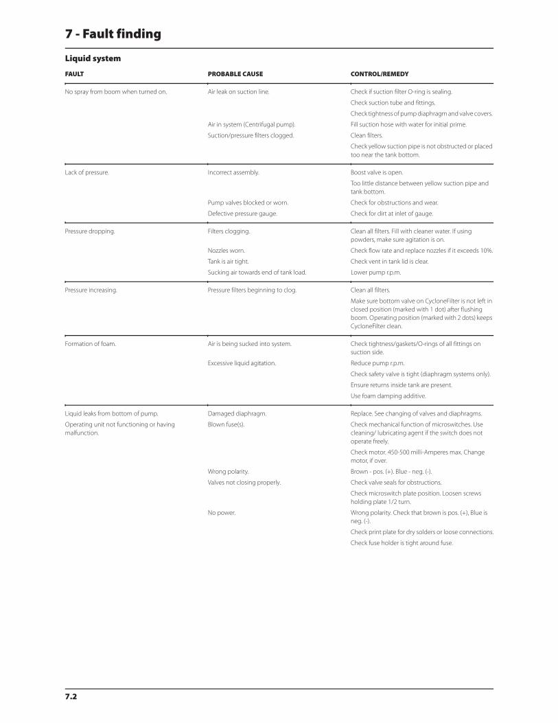
7 - Fault finding
7.2
Liquid system
FAULT PROBABLE CAUSE CONTROL/REMEDY
No spray from boom when turned on. Air leak on suction line. Check if suction filter O-ring is sealing.
Check suction tube and fittings.
Check tightness of pump diaphragm and valve covers.
Air in system (Centrifugal pump). Fill suction hose with water for initial prime.
Suction/pressure filters clogged. Clean filters.
Check yellow suction pipe is not obstructed or placed
too near the tank bottom.
Lack of pressure. Incorrect assembly. Boost valve is open.
Too little distance between yellow suction pipe and
tank bottom.
Pump valves blocked or worn. Check for obstructions and wear.
Defective pressure gauge. Check for dirt at inlet of gauge.
Pressure dropping. Filters clogging. Clean all filters. Fill with cleaner water. If using
powders, make sure agitation is on.
Nozzles worn. Check flow rate and replace nozzles if it exceeds 10%.
Tank is air tight. Check vent in tank lid is clear.
Sucking air towards end of tank load. Lower pump r.p.m.
Pressure increasing. Pressure filters beginning to clog. Clean all filters.
Make sure bottom valve on CycloneFilter is not left in
closed position (marked with 1 dot) after flushing
boom. Operating position (marked with 2 dots) keeps
CycloneFilter clean.
Formation of foam. Air is being sucked into system. Check tightness/gaskets/O-rings of all fittings on
suction side.
Excessive liquid agitation. Reduce pump r.p.m.
Check safety valve is tight (diaphragm systems only).
Ensure returns inside tank are present.
Use foam damping additive.
Liquid leaks from bottom of pump. Damaged diaphragm. Replace. See changing of valves and diaphragms.
Operating unit not functioning or having
malfunction.
Blown fuse(s). Check mechanical function of microswitches. Use
cleaning/ lubricating agent if the switch does not
operate freely.
Check motor. 450-500 milli-Amperes max. Change
motor, if over.
Wrong polarity. Brown - pos. (+). Blue - neg. (-).
Valves not closing properly. Check valve seals for obstructions.
Check microswitch plate position. Loosen screws
holding plate 1/2 turn.
No power. Wrong polarity. Check that brown is pos. (+), Blue is
neg. (-).
Check print plate for dry solders or loose connections.
Check fuse holder is tight around fuse.

7 - Fault finding
7.3
Hydraulic system - I.A.H.
FAULT PROBABLE CAUSE CONTROL/REMEDY
Boom slow/erratic. Air in system. Loosen ram connection and activate hydraulics until
oil flow has no air in it (not whitish).
Regulation valve incorrectly set. Open or close until desired speed is achieved
(clockwise = less speed).
Remember oil must be at operating temperature.
Insufficient hydraulic pressure. Check output pressure of tractor hydraulics. Minimum
for sprayer is 2500 psi (170 bar).
Insufficient amount of oil in tractor reservoir. Check and top if needed.
Ram not functioning. Restrictor or regulation valve blocked. Secure boom. Dismantle and clean.
Hydraulic system fold/tilt functions will not operate. Power supply. Check for proper 12V power supply.
One function (fold or tilt) will not operate. Various. Check for defective switch(es).
Check continuity of cables.
Check for operation of applicable solenoid (coil not
activating or plunger stuck).
Check for short circuit in wiring junction box at rear of
sprayer.
Dirt in the restrictor port of the cylinder.
Multiple hydraulic functions with one switch
activated.
Various. Check for correct solenoid electric/hydraulic hook-up.
Check for short circuit in wiring in the junction box at
rear of sprayer.

7 - Fault finding
7.4
Mechanical problems
Mechanical problems
Emergency operation - Liquid system
In case of power failure it is possible to operate all functions of the operating unit manually. First disconnect the multi plug
from the control box. Now manually turn the emergency control knobs.
The problem may be due to a blown fuse. A fuse is placed inside the box. Fuse type: Thermo
FAULT PROBABLE CAUSE CONTROL/REMEDY
Boom will not fold in or out. Cylinder. Adjust the fold cylinder.
Boom will not fold completely. Cables. Check adjustment of center cables.
Boom not aligned. Cables. Adjust and grease complete boom cables and stops.
Boom will not stay in spraying position. Various. Check for hydraulic leaks through solenoid block.
Check for a solenoid that is stuck open.
Wing to be kept folded swings out when unfolding
other side of the boom.
Various. Boom must be completely unfolded - then fold out
the desired boom wing.
Check for hydraulic leaks through solenoid block.
Check for a solenoid that is stuck open.
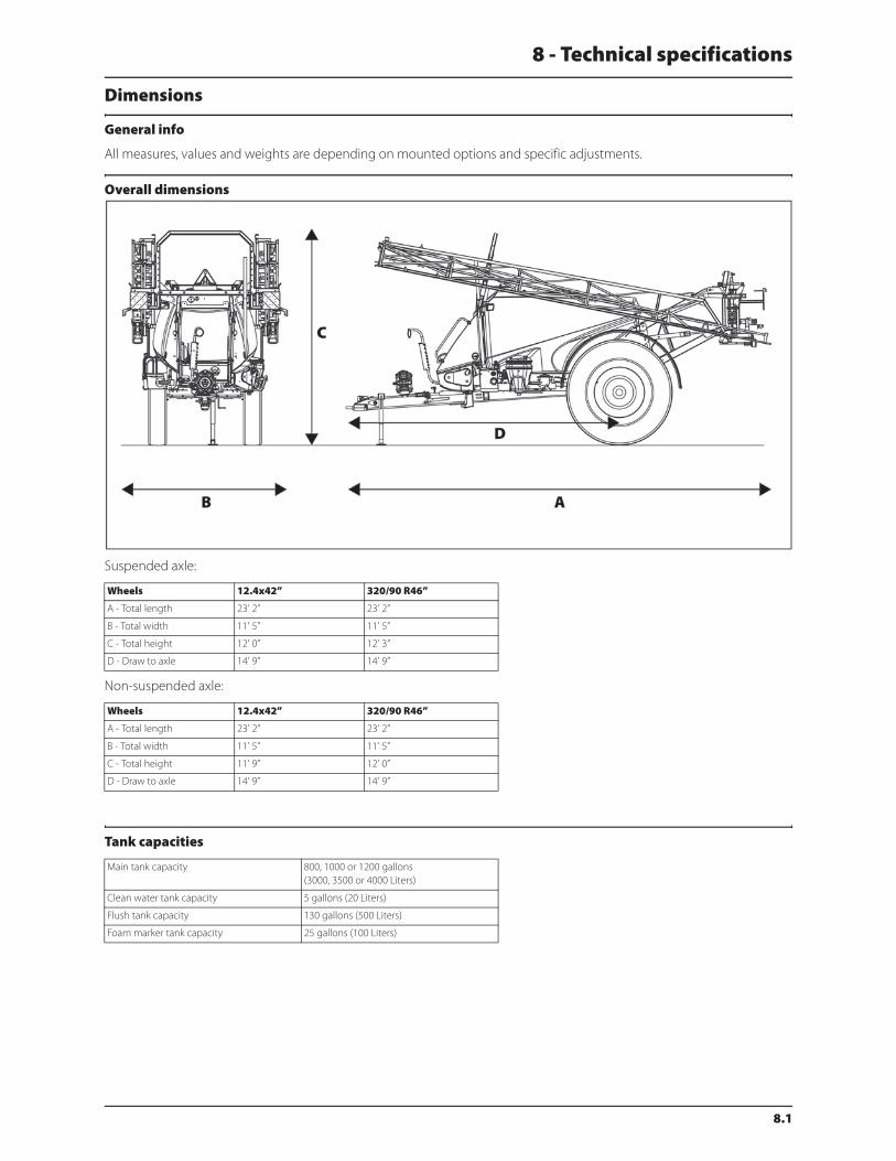
8.1
8 - Technical specifications
Dimensions
General info
All measures, values and weights are depending on mounted options and specific adjustments.
Overall dimensions
Suspended axle:
Non-suspended axle:
Tank capacities
Wheels 12.4x42” 320/90 R46”
A - Total length 23’ 2” 23’ 2”
B - Total width 11’ 5” 11’ 5”
C - Total height 12’ 0” 12’ 3”
D - Draw to axle 14’ 9” 14’ 9”
Wheels 12.4x42” 320/90 R46”
A - Total length 23’ 2” 23’ 2”
B - Total width 11’ 5” 11’ 5”
C - Total height 11’ 9” 12’ 0”
D - Draw to axle 14’ 9” 14’ 9”
Main tank capacity 800, 1000 or 1200 gallons
(3000, 3500 or 4000 Liters)
Clean water tank capacity 5 gallons (20 Liters)
Flush tank capacity 130 gallons (500 Liters)
Foam marker tank capacity 25 gallons (100 Liters)
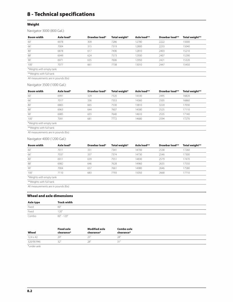
8 - Technical specifications
8.2
Weight
Navigator 3000 (800 Gal.):
Navigator 3500 (1000 Gal.):
Navigator 4000 (1200 Gal.):
Wheel and axle dimensions
Boom width Axle load* Drawbar load* Total weight* Axle load** Drawbar load** Total weight**
60’ 6978 309 7286 12780 2222 15000
66’ 7004 315 7319 12800 2233 15040
80’ 6878 617 7496 12810 2403 15210
88’ 6949 624 7573 12930 2407 15290
90’ 6971 635 7606 12950 2421 15320
100’ 7077 661 7738 13010 2447 15450
*Weights with empty tank
**Weights with full tank
All measurements are in pounds (lbs)
Boom width Axle load* Drawbar load* Total weight* Axle load** Drawbar load** Total weight**
60’ 6991 329 7320 14330 2495 16820
66’ 7017 336 7353 14360 2505 16860
80’ 6865 665 7530 13810 3220 17030
88’ 6963 644 7607 14580 2525 17110
90’ 6985 655 7640 14610 2535 17140
100’ 7091 681 7772 14680 2594 17270
*Weights with empty tank
**Weights with full tank
All measurements are in pounds (lbs)
Boom width Axle load* Drawbar load* Total weight* Axle load** Drawbar load** Total weight**
60’ 7011 331 7341 14700 2538 17260
66’ 7037 337 7374 14730 2546 17300
80’ 6911 639 7551 14830 2579 17470
88’ 6982 646 7628 14960 2635 17550
90’ 7004 657 7661 14980 2646 17580
100’ 7110 683 7793 15050 2668 17710
*Weights with empty tank
**Weights with full tank
All measurements are in pounds (lbs)
Axle type Track width
Fixed 60”
Fixed 120”
Combo 60” - 120”
WheelFixed axleclearance*
Modified axleclearance*
Combo axleclearance*
12.4 x 42 29” 25” 28”
320/90 R46 32” 28” 31”
*under axle
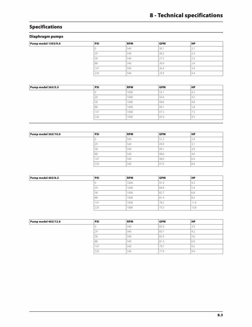
8 - Technical specifications
8.3
Specifications
Diaphragm pumps
Pump model 1303/9.0 PSI RPM GPM HP
0 540 30.1 2.1
29 540 28.2 2.3
58 540 27.5 2.3
88 540 26.9 2.4
147 540 26.4 3.4
220 540 25.9 4.4
Pump model 363/5.5 PSI RPM GPM HP
0 1000 53.1 4.2
29 1000 50.4 4.3
58 1000 49.6 4.8
88 1000 49.1 5.8
147 1000 47.5 7.5
220 1000 45.9 9.5
Pump model 363/10.0 PSI RPM GPM HP
0 540 51.2 2.4
29 540 49.9 3.1
58 540 49.1 3.9
88 540 48.6 4.6
147 540 48.0 6.4
220 540 47.0 8.4
Pump model 463/6.5 PSI RPM GPM HP
0 1000 91.9 4.3
29 1000 84.8 5.4
58 1000 82.7 6.8
88 1000 81.4 8.3
147 1000 78.2 11.0
220 1000 75.5 13.8
Pump model 463/12.0 PSI RPM GPM HP
0 540 85.0 3.0
29 540 83.7 4.2
58 540 82.9 5.6
88 540 81.3 6.9
147 540 79.7 9.5
220 540 77.9 9.9
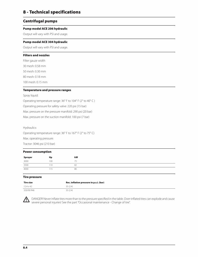
8 - Technical specifications
8.4
Centrifugal pumps
Pump model ACE 206 hydraulic
Output will vary with PSI and usage.
Pump model ACE 304 hydraulic
Output will vary with PSI and usage.
Filters and nozzles
Filter gauze width
30 mesh: 0.58 mm
50 mesh: 0.30 mm
80 mesh: 0.18 mm
100 mesh: 0.15 mm
Temperature and pressure ranges
Spray liquid:
Operating temperature range: 36° F to 104° F (2° to 40° C )
Operating pressure for safety valve: 220 psi (15 bar)
Max. pressure on the pressure manifold: 290 psi (20 bar)
Max. pressure on the suction manifold: 100 psi (7 bar)
Hydraulics:
Operating temperature range: 36° F to 167° F (2° to 75° C)
Max. operating pressure:
Tractor: 3046 psi (210 bar)
Power consumption
Tire pressure
€ DANGER! Never inflate tires more than to the pressure specified in the table. Over-inflated tires can explode and cause
severe personal injuries! See the part “Occasional maintenance - Change of tire”.
Sprayer Hp kW
3000 100 75
3500 110 82
4000 115 86
Tire size Rec. inflation pressure in p.s.i. (bar)
12.4 x 42 35 (2.4)
320/90 R46 35 (2.4)

8 - Technical specifications
8.5
Materials and recycling
Disposal of the sprayer
When the equipment has completed its working life, it must be thoroughly cleaned. The tank, hose and synthetic fittings
can be incinerated at an authorized disposal plant. The metallic parts can be scrapped. Always follow local legislation
regarding disposal.
Materials used:
Tanks: HDPE
Frame etc.: Steel
Pump: Cast iron
Diaphragms: PUR
Hoses (suction): PVC
Hoses (pressure): EPDM
Valves: Glass reinforced PA Filters: PP
Nozzles: Unfilled POM
Fittings: Glass reinforced PA
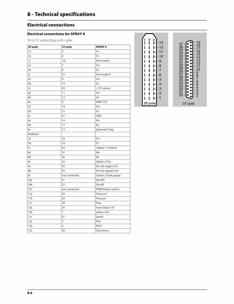
8 - Technical specifications
8.6
Electrical connections
Electrical connections for SPRAY II
39 or 37 poled plug with cable.
39-pole 37-pole SPRAY II
1a 5 S1+
1b 6 S1-
1c 26 End nozzle L
2a 7 S2+
2b 8 S2-
2c 25 End nozzle R
3a 9 S3+
3b 10 S3-
3c 29 +12V sensor
4a 11 S4+
4b 12 34-
4c 4 PWM 1TX
5a 14 S5+
5b 15 S5-
5c 27 GND
6a 16 S6+
6b 17 S6-
6c 13 Optional 5 Reg.
feedback
7a 18 S7+
7b 19 S7-
7c 33 Option 1 4-20mA
8a 37 S8+
8b 36 S8-
8c 32 Option 2 Frq
9a 35 S9+/Air angle 0-5V
9b 34 S9-/Fan speed 0-5V
9c not connected Option 3/Tank gauge
10a 21 On/off+
10b 22 On/off-
10c not connected PWM Output option
11a 23 Pressure+
11b 24 Pressure-
11c 28 Flow
12a 20 Foam blop 0-5V
12b 1 option 4 Rx
12c 31 Speed
13a 3 FM L
13b 2 FM R
13c 30 Gnd sensor
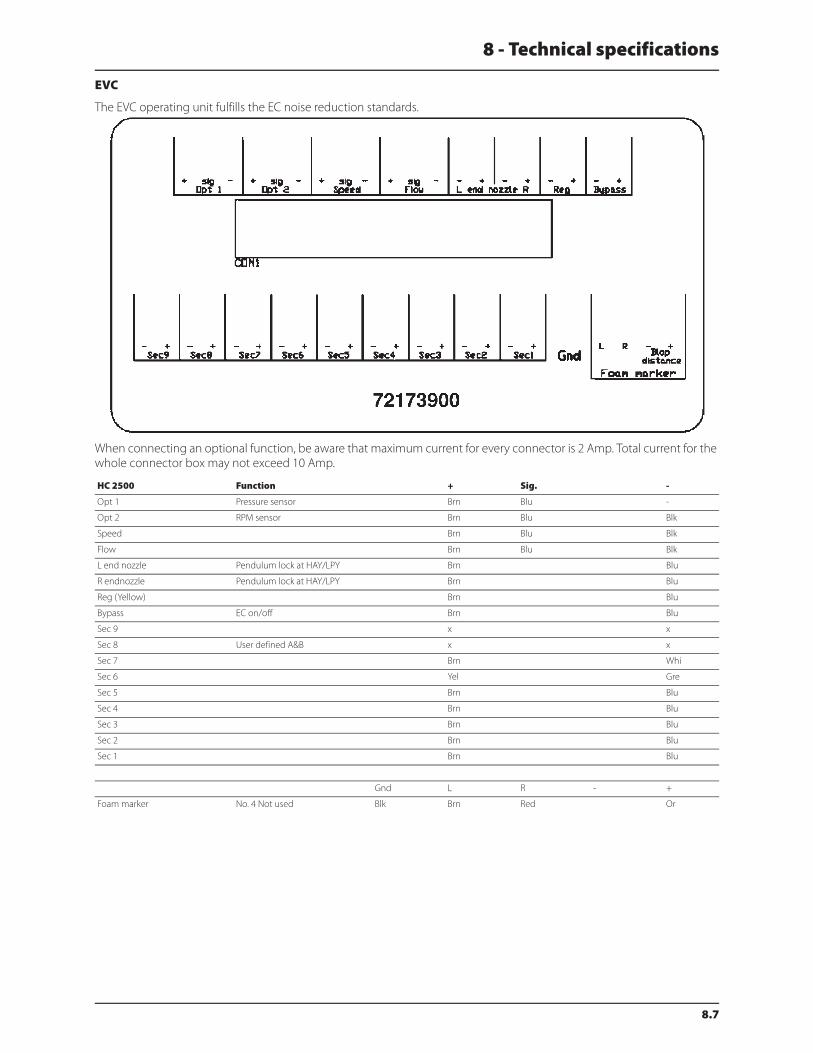
8 - Technical specifications
8.7
EVC
The EVC operating unit fulfills the EC noise reduction standards.
When connecting an optional function, be aware that maximum current for every connector is 2 Amp. Total current for the
whole connector box may not exceed 10 Amp.
HC 2500 Function + Sig. -
Opt 1 Pressure sensor Brn Blu -
Opt 2 RPM sensor Brn Blu Blk
Speed Brn Blu Blk
Flow Brn Blu Blk
L end nozzle Pendulum lock at HAY/LPY Brn Blu
R endnozzle Pendulum lock at HAY/LPY Brn Blu
Reg (Yellow) Brn Blu
Bypass EC on/off Brn Blu
Sec 9 x x
Sec 8 User defined A&B x x
Sec 7 Brn Whi
Sec 6 Yel Gre
Sec 5 Brn Blu
Sec 4 Brn Blu
Sec 3 Brn Blu
Sec 2 Brn Blu
Sec 1 Brn Blu
Gnd L R - +
Foam marker No. 4 Not used Blk Brn Red Or

8 - Technical specifications
8.8
Plug positions for HZ hydraulics
1. Fold left
2. Fold left
3. Tilt left down
4. Tilt left up
5. Tilt right down
6. Tilt right up
7. Fold right
8. Fold right
9. (B) flow reverse
10. (A) flow forward
Road traffic lights
The wiring is in accordance with ANSI/ASAE S279.11.
HC 5500 Function + Sig. -
Opt 1 Pressure sensor Brn Blu -
Opt 2 RPM sensor or anemometer Brn Blu Blk
Speed Brn Blu Blk
Flow Brn Blu Blk
L end nozzle Pendulum lock at HAY/LPY Brn Blu
R endnozzle Pendulum lock at HAY/LPY Brn Blu
Reg (Yellow) Brn Blu
Bypass EC on/off Brn Blu
Sec 9 User defined A&B 2 x x
Sec 8 User defined A&B 1 x x
Sec 7 Twin speed Brn Whi
Sec 6 Twin angle Yel Gre
Sec 5 Brn Blu
Sec 4 Brn Blu
Sec 3 Brn Blu
Sec 2 Brn Blu
Sec 1 Brn Blu
Gnd L R - +
Foam marker No. 4 Not used 2 6 5 1 3
Position Wire color
1. Ground White
2. Work lamps Black
3. LH flashing & turn indicator Yellow
4. Free Red
5. RH flashing & turn indicator Green
6. Free Brown
7. Free Blue

8 - Technical specifications
8.9
Charts
Boom hydraulics - HY
Boom hydraulics - HZ
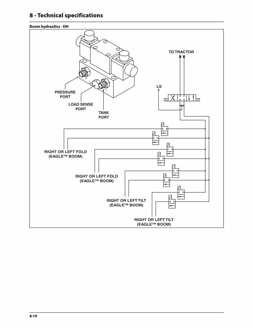
8 - Technical specifications
8.10
Boom hydraulics - DH

8 - Technical specifications
8.11
Electrical specifications for boom and work light

8 - Technical specifications
8.12

9 - Warranty
9.1
9 - Warranty
Warranty policy and conditions
HARDI® NORTH AMERICA INC. , 1500 West 76th Street, Davenport, Iowa, USA and 337 Sovereign Road, London, Ontario,
Canada hereinafter called “HARDI®”, offers the following limited warranty in accordance with the provisions below to each
original retail purchaser of its own manufacturer, from an authorized HARDI® dealer that such equipment is at the time of
delivery to such purchaser, free from defects in material and workmanship and that such equipment will be warranted for a
period of one year from the time of delivery to the end user, providing the machine is used and serviced in accordance with
the recommendations in the Operator’s Manual and is operated under normal farm conditions.
1. This limited warranty is subject to the following exceptions:
a)Parts of the machine not manufactured by HARDI®, (i.e. engines, tires, tubes, electronic controls and other
components or trade accessories, etc.) are not covered by this warranty but are subject to the warranty of the
original manufacturer. Any claim falling into this category will be taken up with the manufacturer concerned.
b)This warranty will be withdrawn if any equipment has been used for purposes other than for which it was intended
or if it has been misused, neglected, or damaged by accident, let out on hire or furnished by a rental agency. Nor
can claims be accepted if parts other than those manufactured by HARDI® have been incorporated in any of our
equipment. Further, HARDI® shall not be responsible for damage in transit or handling by any common carrier and
under no circumstances within or without the warranty period will HARDI® be liable for damages of loss of use, or
damages resulting from delay or any consequential damage.
2. We cannot be held responsible for loss of livestock, loss of crops, loss because of delays in harvesting or any other
expense or loss incurred for labor, supplies, substitute machinery, rental for any other reason, or for injuries either to
the owner or to a third party, nor can we be called upon to be responsible for labor charges, other than originally
agreed, incurred in the removal or replacement of components.
3. The customer will be responsible for and bear the costs of:
a)Normal maintenance such as greasing, maintenance of oil levels, minor adjustments including the boom.
b)Transportation of any HARDI® product to and from where the warranty work is to be performed.
c)Dealer travel time to and from the machine or to deliver and return the machine from the service workshop for
repair unless otherwise dictated by state law.
d)Dealer traveling costs.
4. Parts defined as normal wearing items, (i.e. Pump Diaphragms, Valves, O-rings, Tires and V-belts) are not in any way
covered under this warranty.
5. This warranty will not apply to any product which is altered or modified without the express written permission of
the HARDI® Service and Engineering Departments and/or repaired by anyone other than an Authorized HARDI®
Dealer.
6. Warranty is dependent upon the strict observance by the purchaser of the following provisions:
a)That this warranty may not be assigned or transferred to anyone.
b)That the Warranty Registration Certificate has been correctly completed by dealer and purchaser with their names
and addresses, dated, signed and returned to the appropriate address as given on the Warranty Registration
Certificate within 30 days of delivery to the purchaser.
c)That all safety instructions in the operator’s manual shall be followed and all safety guards regularly inspected and
replaced where necessary.
7. No warranty is given on second-hand products and none is implied.
8. Subject to the following terms, conditions and contributions, HARDI® extends the warranty on polyethylene tanks
(excluding fittings, lids and gaskets) to FIVE YEARS on field sprayers and TEN YEARS on Orchard and Vineyard sprayers.
To qualify for this extended warranty, the tank must be drained and flushed with fresh water after each day’s use.
HARDI®’s liability is limited to replacement of defective parts FOB our plants in Davenport, IA and London, Ontario,
Canada at no cost to the purchaser for the first twelve months after date of purchase; at 20% of the then current retail
price during the second year; at 40% during the third year; at 60% during the fourth year; and at 80% during the fifth
year. This extended warranty is subject, in each instance, to the tank being inspected and approved for replacement
or repair by HARDI® personnel before HARDI® will accept any liability hereunder.

9 - Warranty
9.2
9. Subject to the following terms, conditions and contributions, HARDI® extends the warranty on HARDI® diaphragm
pumps (excluding wearing parts such as diaphragms, valves and o-rings) to FIVE YEARS. To qualify for this extended
warranty, the pump must be drained and flushed with fresh water after each day’s use. HARDI®’s liability is limited to
replacement of defective parts, FOB our plants in Davenport, IA and London, Ontario, Canada at no cost to the to the
purchaser during the first twelve months after date of purchase; at 20% of the then current retail price during the
second year; at 40% during the third year; at 60% during the fourth year; and at 80% during the fifth year. This five
year extended warranty is subject, in each instance, to the pump being inspected and approved for replacement or
repair by HARDI® personnel before HARDI® will accept any liability hereunder.
10. HARDI® reserves the right to incorporate any change in design in its products without obligation to make such
changes on units previously manufactured.
11. The judgement of the HARDI® Service Department in all cases of claims under this warranty shall be final and
conclusive and the purchaser agrees to accept its decisions on all questions as to defect and the repair or exchange
of any part or parts.
12. No employee or representative is authorized to change this warranty in any way or grant any other warranty unless
such change is made in writing and signed by the CEO in the Davenport office. Approval of warranty is the
responsibility of the HARDI® Service Department.
13. Any warranty work performed which will exceed $1000.00 MUST be approved IN ADVANCE by the Service
Department. Warranty claims filed without prior approval will be returned.
14. ANY pump replacement MUST be approved by the HARDI® Service Department.
15. Claims under this policy MUST be filed with the HARDI® Service Department within thirty (30) days of when the work
is performed or warranty shall be void unless prior arrangements are made.
16. Parts which are requested for return by the HARDI® Service Department must be returned prepaid within thirty (30)
days for warranty settlement.
17. Warranty claims must be COMPLETELY filled out including part numbers and quantities or claims will be returned to
the submitting dealer.
DISCLAIMER OF FURTHER WARRANTY
THERE ARE NO WARRANTIES, EXPRESSED OR IMPLIED, EXCEPT AS SET FORTH ABOVE. THERE ARE NO WARRANTIES
WHICH EXTEND BEYOND THE DESCRIPTION OF THE PRODUCT CONTAINED HEREIN. IN NO EVENT SHALL THE
COMPANY BE LIABLE FOR INDIRECT, SPECIAL OR CONSEQUENTIAL DAMAGES (SUCH AS LOSS OF ANTICIPATED
PROFITS) IN CONNECTION WITH THE RETAIL PURCHASER’S USE OF THE PRODUCT.


1500 West 76th St.Davenport, Iowa 52806Phone: (563) 386-1730Fax: (563) 386-1710
337 Sovereign Rd.London, Ontario N6M 1A6Phone: (519) 659-2771Fax: (519) 659-2821
For Product, Service or Warranty Information:- Please contact your local HARDI® dealer.To contact HARDI® directly:- Please use the HARDI® Customer Service number: 1-866-770-7063- Or send your email to: [email protected]
HARDI® NORTH AMERICA INC.
Visit us online at: www.hardi-us.com
Related Documents


![Engine Powered Forklift 8FG/8FD 3.5 to 8.0 Ton Series · 2 3 MAIN VEHICLE SPECIFICATIONS Manufacturer TOYOTA TOYOTA Model 8FG35N 8FD35N Load Capacity kg 3500 [4000] 3500 [4000] Load](https://static.cupdf.com/doc/110x72/5e55d3020a9911686a41ef8b/engine-powered-forklift-8fg8fd-35-to-80-ton-series-2-3-main-vehicle-specifications.jpg)