SECTION 5 RIGID PAVEMENT CONSTRUCTION Standard Specification for Urban Infrastructure Works 5-1 Edition 1, Revision 0 / September 2002 CONTENTS 5 RIGID PAVEMENT CONSTRUCTION 5-3 5.01 SCOPE 5-3 5.02 STANDARDS 5-3 5.03 MATERIALS FOR CONCRETE BASE 5-5 5.03.1 Cement and Flyash 5-5 5.03.2 Aggregates 5-5 5.03.3 Admixtures 5-8 5.03.4 Concrete 5-8 5.03.5 Reinforcement, Tie Bars and Dowels 5-10 5.03.6 Joint Sealers 5-10 5.03.7 Curing Materials 5-14 5.04 EARTHWORKS 5-15 5.05 CONCRETE SUBBASE 5-15 5.05.1 Materials for Concrete Subbase 5-15 5.05.2 Construction of Concrete Subbase 5-17 5.05.3 Subgrade Beams 5-17 5.05.4 Joints in Concrete Subbase 5-18 5.05.5 Preparation for placement of Concrete Base 5-19 5.06 FORMWORK 5-19 5.06.1 General 5-19 5.06.2 Fixed Formwork 5-20 5.07 REINFORCEMENT, DOWELS AND TIE BARS 5-20 5.08 PRODUCTION, TRANSPORT AND CONSITENCY OF CONCRETE 5-21 5.08.1 Production And Handling Of Concrete 5-21 5.08.2 Placing in Fixed Forms 5-22 5.08.3 Mixing Time 5-23 5.08.4 Consistency 5-23 5.09 PLACING AND FINISHING 5-23 5.09.1 Trial Section 5-24 5.09.2 Placing in Fixed Forms – Hand Placing 5-24 5.09.3 Slip-Form Placement – Mechanical Paving 5-25 5.09.4 Rate of Evaporation 5-26 5.09.5 Slab Anchors 5-28 5.10 JOINTS IN CONCRETE BASE 5-28 5.10.1 General 5-28 5.10.2 Construction Joints 5-29 5.10.3 Expansion Joints 5-30 5.10.4 Contraction Joints 5-31 5.10.5 Grooving and Sealing 5-33 5.11 CURING AND PROTECTION 5-34 5.11.1 General 5-34 5.11.2 Membrane Curing 5-35

Welcome message from author
This document is posted to help you gain knowledge. Please leave a comment to let me know what you think about it! Share it to your friends and learn new things together.
Transcript
8/2/2019 6503712 Rigid Pavement SS05
http://slidepdf.com/reader/full/6503712-rigid-pavement-ss05 1/49
SECTION 5 RIGID PAVEMENT
CONSTRUCTION
Standard Specification for Urban Infrastructure Works 5-1
Edition 1, Revision 0 / September 2002
CONTENTS
5 RIGID PAVEMENT CONSTRUCTION 5-3
5.01 SCOPE 5-3
5.02 STANDARDS 5-3
5.03 MATERIALS FOR CONCRETE BASE 5-5 5.03.1 Cement and Flyash 5-5 5.03.2 Aggregates 5-5 5.03.3 Admixtures 5-8 5.03.4 Concrete 5-8 5.03.5 Reinforcement, Tie Bars and Dowels 5-10 5.03.6 Joint Sealers 5-10 5.03.7 Curing Materials 5-14
5.04 EARTHWORKS 5-15
5.05 CONCRETE SUBBASE 5-15 5.05.1 Materials for Concrete Subbase 5-15 5.05.2 Construction of Concrete Subbase 5-17 5.05.3 Subgrade Beams 5-17 5.05.4 Joints in Concrete Subbase 5-18 5.05.5 Preparation for placement of Concrete Base 5-19
5.06 FORMWORK 5-19
5.06.1 General 5-19 5.06.2 Fixed Formwork 5-20
5.07 REINFORCEMENT, DOWELS AND TIE BARS 5-20
5.08 PRODUCTION, TRANSPORT AND CONSITENCY OF CONCRETE 5-21 5.08.1 Production And Handling Of Concrete 5-21 5.08.2 Placing in Fixed Forms 5-22 5.08.3 Mixing Time 5-23 5.08.4 Consistency 5-23
5.09 PLACING AND FINISHING 5-23 5.09.1 Trial Section 5-24 5.09.2 Placing in Fixed Forms – Hand Placing 5-24 5.09.3 Slip-Form Placement – Mechanical Paving 5-25 5.09.4 Rate of Evaporation 5-26 5.09.5 Slab Anchors 5-28
5.10 JOINTS IN CONCRETE BASE 5-28 5.10.1 General 5-28 5.10.2 Construction Joints 5-29 5.10.3 Expansion Joints 5-30 5.10.4 Contraction Joints 5-31 5.10.5 Grooving and Sealing 5-33
5.11 CURING AND PROTECTION 5-34 5.11.1 General 5-34 5.11.2 Membrane Curing 5-35
8/2/2019 6503712 Rigid Pavement SS05
http://slidepdf.com/reader/full/6503712-rigid-pavement-ss05 2/49
SECTION 5 RIGID PAVEMENT
CONSTRUCTION
Standard Specification for Urban Infrastructure Works 5-2
Edition 1, Revision 0 / September 2002
5.11.3 Initial Curing 5-36 5.11.4 Moist Curing 5-36 5.11.5 Impermeable Blanket Curing 5-36
5.12 MAKING GOOD 5-36
5.13 PROTECTION OF WORK 5-37
5.14 CONFORMANCE CRITERIA 5-37 5.14.1 Compressive Strength of Concrete 5-37 5.14.2 Compaction and Tolerances 5-40 5.14.3 Specimens cut from the Work 5-42 5.14.4 Sampling and Testing 5-43 5.14.5 Frequency of Testing 5-43 5.14.6 Nonconforming Work 5-45
5.15
MEASUREMENT AND PAYMENT 5-47
5.16 SCHEDULE OF HOLD POINTS 5-49

8/2/2019 6503712 Rigid Pavement SS05
http://slidepdf.com/reader/full/6503712-rigid-pavement-ss05 3/49
SECTION 5 RIGID PAVEMENT
CONSTRUCTION
Standard Specification for Urban Infrastructure Works 5-3
Edition 1, Revision 0 / September 2002
5 RIGID PAVEMENT CONSTRUCTION
5.01 SCOPE
The works covered by this Section of the Specification comprise the construction of portland cement concrete
pavements.
5.02 STANDARDS
Work carried out and testing performed under this Section of the Specification shall comply with the
requirements of the following Standards to the extent that they are relevant and not overridden by the
Specification.
Australian Standards
AS 1012 Methods of Testing Concrete
AS 1012.1 Sampling fresh concrete
AS 1012.3.1 Determination of properties related to the consistence of concrete - Slump test.
AS 1012.4.2 Determination of air content of freshly mixed concrete - Measuring reduction in air
pressure in chamber above concrete.
AS 1012.8 Making and curing concrete compression, indirect tensile and flexure test specimens in
the laboratory or in the field.
AS 1012.9 Determination of the compressive strength of concrete specimens.
AS 1012.12.2 Determination of mass per unit volume of hardened concrete - Water displacement
method.
AS 1012.13 Determination of the drying shrinkage of concrete for samples prepared in the field or in
the laboratory.
AS 1012.14 Securing and testing cores from hardened concrete for compressive strength or indirect
tensile strength.
AS 1141 Methods of Sampling and Testing Aggregate
AS 1141.11 Particle size distribution by dry sieving.
AS 1141.14 Particle shape by proportional calliper.
AS 1141.18 Crushed particles of coarse aggregates.
AS 1141.22 Wet/dry strength variation.
AS 1141.24 Soundness (by use of sodium sulphate solution).
AS 1160 Bitumen Emulsions for Construction and Maintenance of Pavements
AS 1302 Steel Reinforcing Bars for Concrete
AS 1303 Steel Reinforcing Wire for Concrete
AS 1304 Steel Wire Reinforcing Fabric for Concrete
8/2/2019 6503712 Rigid Pavement SS05
http://slidepdf.com/reader/full/6503712-rigid-pavement-ss05 4/49
SECTION 5 RIGID PAVEMENT
CONSTRUCTION
Standard Specification for Urban Infrastructure Works 5-4
Edition 1, Revision 0 / September 2002
AS 1379 The specification and manufacture of concrete.
AS 1478 Chemical admixtures in concrete.
AS 1554.3 Welding of reinforcing steel.
AS 2758 Aggregates & Rock for Engineering Purposes
AS 2758.1 Concrete aggregates
AS 3582.1 Supplementary Cementitious materials - flyash.
AS 3610 Formwork for Concrete
AS 3799 Liquid membrane - forming curing compounds for concrete.
AS 3972 Portland and blended cement.
AS 1348 G1ossary of Terms Used In Road Engineering
RTA, NSW Test Methods
RTA T1192 Adhesion of Sealant.
RTA T1193 Accelerated Ageing of Cured Sealant
ASTM Standards
C171 Sheet Materials for Curing Concrete
C309 Liquid Membrane Forming Compounds for Curing Concrete
D792 Test Method for Specific Gravity (Relative Density) and Density of Plastics by
Displacement.
C793 Test Method for Effects of Accelerated Weathering on Elastomeric Joint Sealants.
C794 Test Method for Adhesion-in-Peel of Elastomeric Joint Sealants.
D2240 Test Method for Rubber Property Durometer Hardness.
D2628 Performed Polychloroprene Elastomeric Joint Seals for Concrete Pavements.
D2835 Specification for Lubricant for Installation of Preformed Compression Seal in Concrete
Pavements.
US Military Standards
MIL-S-8802 Sealing Compound, Temperature Resistant, Integral Fuel Tanks and Fuel Cell Cavities,
High Adhesion.
Definitions
Terms used to describe the various elements of pavement structure in this section are in accordance with the
definitions prescribed in AS 1348 "Glossary of Terms Used in Road Engineering"

8/2/2019 6503712 Rigid Pavement SS05
http://slidepdf.com/reader/full/6503712-rigid-pavement-ss05 5/49
SECTION 5 RIGID PAVEMENT
CONSTRUCTION
Standard Specification for Urban Infrastructure Works 5-5
Edition 1, Revision 0 / September 2002
Testing
A Testing Authority shall be employed by the Contractor to carry out all testing. The Authority shall hold a
current NATA (National Association of Testing Authorities) Registration for the relevant tests, and a copy of
results shall be forwarded to the Superintendent without delay.
5.03 MATERIALS FOR CONCRETE BASE
5.03.1 Cement and Flyash
Cement shall be Type GP Portland cement complying with AS 3972. When submitting details of the nominated
mix in accordance with Clause 5.03.3 the Contractor shall nominate the brand and source of the cement. On
approval of a nominated mix by the Superintendent, the Contractor shall use only the nominated cement in the
work.
Documentary evidence of the quality and source of the cement shall be furnished by the Contractor to the
Superintendent upon request at any stage of the work.
If the Contractor proposes to use cement which has been stored for a period in excess of three months from the
time of manufacture, a re-test shall be required to ensure the cement still complies with AS 3972, before the
cement is used in the work.
The cost of re-testing the cement shall be borne by the Contractor and results of the testing forwarded to the
Superintendent.
Cement shall be transported in watertight containers and shall be protected from moisture until used. Caked or
lumpy cement shall not be used.
The use and quality of flyash shall comply with AS 3582.1. When submitting details of the nominated mix in
accordance with Clause 5.03.3, the Contractor shall nominate the powerhouse source of the flyash. The
Contractor shall use only flyash from the nominated powerhouse.
Documentary evidence of the quality and source of the flyash shall be furnished by the Contractor to the
Superintendent.
5.03.2 Aggregates
(i) General
In addition to properties specified in AS 2758.1, the maximum soluble sulphate salt content of aggregates,expressed as percentage SO3 by mass, shall not exceed 0.1 %.
Aggregates containing more than the maximum permissible amount of sulphates or with visible encrustations of
salts shall be washed and drained before being used in concrete. The Superintendent may direct washing or
rewashing of the aggregates until he is satisfied that harmful quantities of salts are not present.
At least 40 per cent by mass of the total aggregates in the concrete mix shall be quartz sand. Quartz sand is
aggregate having a nominal size of less than 5mm and shall contain at least 70 per cent quartz, by mass. Where
present, chert fragments will be regarded as `quartz' for the purpose of this specification, but the ratio of chert to
quartz shall not exceed unity.
Coarse and fine aggregates shall be washed as necessary or directed to facilitate achievement of the specified
drying shrinkage.
8/2/2019 6503712 Rigid Pavement SS05
http://slidepdf.com/reader/full/6503712-rigid-pavement-ss05 6/49
SECTION 5 RIGID PAVEMENT
CONSTRUCTION
Standard Specification for Urban Infrastructure Works 5-6
Edition 1, Revision 0 / September 2002
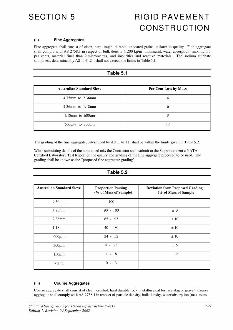
(ii) Fine Aggregates
Fine aggregate shall consist of clean, hard, tough, durable, uncoated grains uniform in quality. Fine aggregate
shall comply with AS 2758.1 in respect of bulk density (1200 kg/m3 minimum), water absorption (maximum 5
per cent), material finer than 2 micrometres, and impurities and reactive materials. The sodium sulphatesoundness, determined by AS 1141.24, shall not exceed the limits in Table 5.1.
Table 5.1
Australian Standard Sieve Per Cent Loss by Mass
4.75mm to 2.36mm 4
2.36mm to 1.18mm 6
1.18mm to 600µm 8
600µm to 300µm 12
The grading of the fine aggregate, determined by AS 1141.11, shall be within the limits given in Table 5.2.
When submitting details of the nominated mix the Contractor shall submit to the Superintendent a NATA
Certified Laboratory Test Report on the quality and grading of the fine aggregate proposed to be used. The
grading shall be known as the "proposed fine aggregate grading".
Table 5.2
Australian Standard Sieve Proportion Passing
(% of Mass of Sample)
Deviation from Proposed Grading
(% of Mass of Sample)
9.50mm 100
4.75mm 90 - 100 ± 3
2.36mm 65 - 95 ± 10
1.18mm 40 - 80 ± 10
600µm 24 - 52 ± 10
300µm 8 - 25 ± 5
150µm 1 - 8 ± 2
75µm 0 - 3
(iii) Course Aggregates
Coarse aggregate shall consist of clean, crushed, hard durable rock, metallurgical furnace slag or gravel. Coarseaggregate shall comply with AS 2758.1 in respect of particle density, bulk density, water absorption (maximum
8/2/2019 6503712 Rigid Pavement SS05
http://slidepdf.com/reader/full/6503712-rigid-pavement-ss05 7/49
SECTION 5 RIGID PAVEMENT
CONSTRUCTION
Standard Specification for Urban Infrastructure Works 5-7
Edition 1, Revision 0 / September 2002
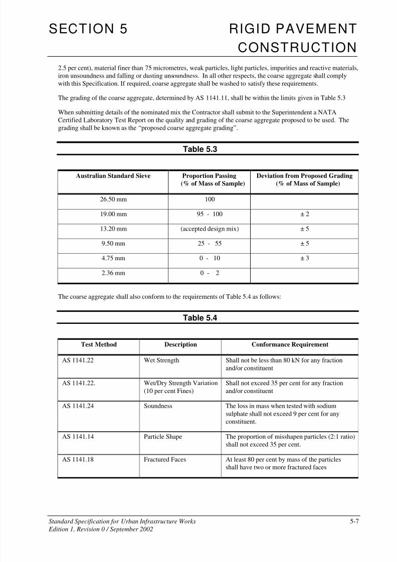
2.5 per cent), material finer than 75 micrometres, weak particles, light particles, impurities and reactive materials,
iron unsoundness and falling or dusting unsoundness. In all other respects, the coarse aggregate shall comply
with this Specification. If required, coarse aggregate shall be washed to satisfy these requirements.
The grading of the coarse aggregate, determined by AS 1141.11, shall be within the limits given in Table 5.3
When submitting details of the nominated mix the Contractor shall submit to the Superintendent a NATA
Certified Laboratory Test Report on the quality and grading of the coarse aggregate proposed to be used. The
grading shall be known as the “proposed coarse aggregate grading”.
Table 5.3
Australian Standard Sieve Proportion Passing
(% of Mass of Sample)
Deviation from Proposed Grading
(% of Mass of Sample)
26.50 mm 100
19.00 mm 95 - 100 ± 2
13.20 mm (accepted design mix) ± 5
9.50 mm 25 - 55 ± 5
4.75 mm 0 - 10 ± 3
2.36 mm 0 - 2
The coarse aggregate shall also conform to the requirements of Table 5.4 as follows:
Table 5.4
Test Method Description Conformance Requirement
AS 1141.22 Wet Strength Shall not be less than 80 kN for any fraction
and/or constituent
AS 1141.22. Wet/Dry Strength Variation
(10 per cent Fines)
Shall not exceed 35 per cent for any fraction
and/or constituent
AS 1141.24 Soundness The loss in mass when tested with sodium
sulphate shall not exceed 9 per cent for any
constituent.
AS 1141.14 Particle Shape The proportion of misshapen particles (2:1 ratio)
shall not exceed 35 per cent.
AS 1141.18 Fractured Faces At least 80 per cent by mass of the particles
shall have two or more fractured faces
8/2/2019 6503712 Rigid Pavement SS05
http://slidepdf.com/reader/full/6503712-rigid-pavement-ss05 8/49
SECTION 5 RIGID PAVEMENT
CONSTRUCTION
Standard Specification for Urban Infrastructure Works 5-8
Edition 1, Revision 0 / September 2002
5.03.3 Admixtures
Chemical admixtures and their use shall comply with AS 1478. Admixtures shall not contain calcium chloride,
calcium formate, or triethanolamine or any other accelerator. Admixtures or combinations of admixtures other
than specified below, shall not be used. An air-entraining agent shall be included in the mix and the air content
of the concrete shall comply with Clause 5.03.4.
During the warm season a lignin or lignin-based (`ligpol') set-retarding admixture (Type Re or Type WR Re)
approved by the Superintendent may be used to control slump within the limits stated in Clause 5.03.4. The
dosage shall be varied to account for air temperature and haul time in accordance with the manufacturer's
recommendations. A copy of the NATA endorsed Certificate of Compliance with AS 1478 for Type Re or Type
WR Re shall be submitted to the Superintendent, together with the proposed `dosage chart' in accordance with
Clause 5.03.4
During the cool season a lignin or lignin based set-retarding admixture containing not more than 6 per cent
reducing sugars (Type WR Re complying with AS 1478) may be used in the mix.
When submitting details of the nominated mix in accordance with Clause 5.03.4, the Contractor shall nominatethe proprietary source, type and name for each admixture to be used. Documentary evidence of the quality shall
be furnished by the Contractor to the Superintendent upon request at any stage of the work.
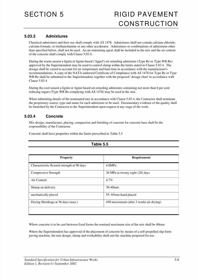
5.03.4 Concrete
Mix design, manufacture, placing, compaction and finishing of concrete for concrete base shall be the
responsibility of the Contractor.
Concrete shall have properties within the limits prescribed in Table 5.5
Table 5.5
Property Requirement
Characteristic flexural strength at 90 days 4.0MPa
Compressive Strength 36 MPa at twenty eight (28) days
Air Content 4.7%
Slump on delivery 30-40mm
mechanically placed 55- 65mm hand placed
Drying Shrinkage at 56 days (max.) 450 microstrain (after 3 weeks air drying)
Where concrete is to be cast between fixed forms the nominal maximum size of the mix shall be 40mm.
Where the Superintendent has approved of the placement of concrete by means of a self-propelled slip-form
paving machine, the mix design, slump and workability shall suit the machine proposed for use.

8/2/2019 6503712 Rigid Pavement SS05
http://slidepdf.com/reader/full/6503712-rigid-pavement-ss05 9/49
SECTION 5 RIGID PAVEMENT
CONSTRUCTION
Standard Specification for Urban Infrastructure Works 5-9
Edition 1, Revision 0 / September 2002
(i) Before commencing production of each concrete mix, the Contractor must:
(a) conduct trial mixes to demonstrate that the proposed mix designs comply with this Specification;
(b) certify that each nominated mix and its constituents meet the requirements of this Specification;
(c) submit NATA endorsed test results for all relevant tests;
Trial mixing must comply strictly with the Contractor’s proposed mix design, including the dilution and
incorporation of admixtures, and the sequence of addition of materials.
Details of the concrete mix designed by the Contractor shall be submitted for approval at least six (6) weeks
before production commences. Information required is itemised below:
(ii) The following details are required for each 'nominated' mix:-
(a) Material Constituents:
• Cement - brand and source.
• Fly ash - powerhouse source.
• Admixtures - proprietary source, type, name and dosage recommended by manufacturer.
• Aggregates - source, geological type, moisture condition on which mix design is based (oven dry,
saturated surface dry or nominated moisture content).
• Relevant test results for all constituents.
• Test results for soluble salt content,.
(b) Mix Design:
• Constituent quantities, per yielded cubic metre of concrete.
• Nominated particle size distribution of aggregates, including fine, coarse and combined particle size
distributions.
(c) Test Results for each trial batch including:
• cement content and fly ash content per yielded cubic metre of concrete;
• compressive strength at age seven (7) days;
• compressive strength at age twenty eight (28) days;
• flexural strength at age seven (7) days;
• flexural strength at age twenty eight (28) days;
• drying shrinkage after twenty one days (21) air drying; and
• air content.
8/2/2019 6503712 Rigid Pavement SS05
http://slidepdf.com/reader/full/6503712-rigid-pavement-ss05 10/49
SECTION 5 RIGID PAVEMENT
CONSTRUCTION
Standard Specification for Urban Infrastructure Works 5-10
Edition 1, Revision 0 / September 2002
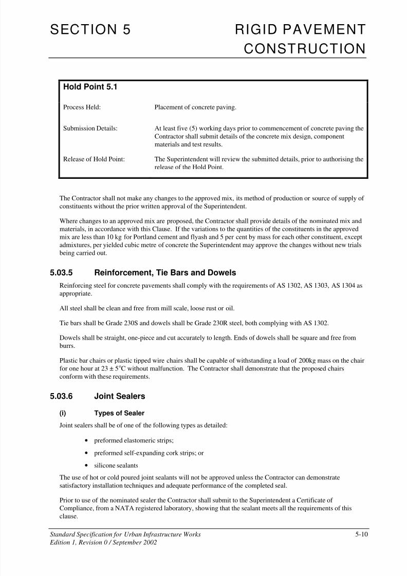
Hold Point 5.1
Process Held: Placement of concrete paving.
Submission Details: At least five (5) working days prior to commencement of concrete paving the
Contractor shall submit details of the concrete mix design, component
materials and test results.
Release of Hold Point: The Superintendent will review the submitted details, prior to authorising the
release of the Hold Point.
The Contractor shall not make any changes to the approved mix, its method of production or source of supply of
constituents without the prior written approval of the Superintendent.
Where changes to an approved mix are proposed, the Contractor shall provide details of the nominated mix and
materials, in accordance with this Clause. If the variations to the quantities of the constituents in the approved
mix are less than 10 kg for Portland cement and flyash and 5 per cent by mass for each other constituent, except
admixtures, per yielded cubic metre of concrete the Superintendent may approve the changes without new trials
being carried out.
5.03.5 Reinforcement, Tie Bars and Dowels
Reinforcing steel for concrete pavements shall comply with the requirements of AS 1302, AS 1303, AS 1304 as
appropriate.
All steel shall be clean and free from mill scale, loose rust or oil.
Tie bars shall be Grade 230S and dowels shall be Grade 230R steel, both complying with AS 1302.
Dowels shall be straight, one-piece and cut accurately to length. Ends of dowels shall be square and free from
burrs.
Plastic bar chairs or plastic tipped wire chairs shall be capable of withstanding a load of 200kg mass on the chair
for one hour at 23 ± 5oC without malfunction. The Contractor shall demonstrate that the proposed chairs
conform with these requirements.
5.03.6 Joint Sealers
(i) Types of Sealer
Joint sealers shall be of one of the following types as detailed:
• preformed elastomeric strips;
• preformed self-expanding cork strips; or
• silicone sealants
The use of hot or cold poured joint sealants will not be approved unless the Contractor can demonstrate
satisfactory installation techniques and adequate performance of the completed seal.
Prior to use of the nominated sealer the Contractor shall submit to the Superintendent a Certificate of
Compliance, from a NATA registered laboratory, showing that the sealant meets all the requirements of this
clause.
8/2/2019 6503712 Rigid Pavement SS05
http://slidepdf.com/reader/full/6503712-rigid-pavement-ss05 11/49
SECTION 5 RIGID PAVEMENT
CONSTRUCTION
Standard Specification for Urban Infrastructure Works 5-11
Edition 1, Revision 0 / September 2002
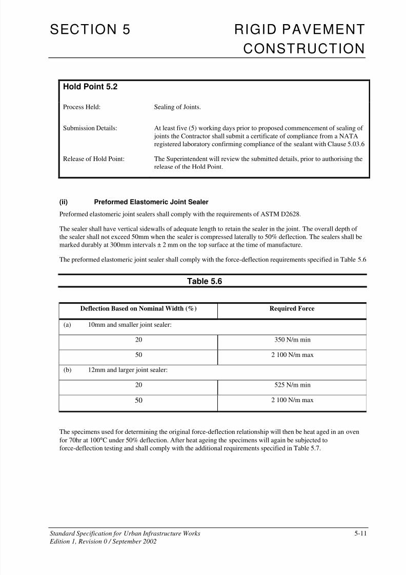
Hold Point 5.2
Process Held: Sealing of Joints.
Submission Details: At least five (5) working days prior to proposed commencement of sealing of
joints the Contractor shall submit a certificate of compliance from a NATA
registered laboratory confirming compliance of the sealant with Clause 5.03.6
Release of Hold Point: The Superintendent will review the submitted details, prior to authorising the
release of the Hold Point.
(ii) Preformed Elastomeric Joint Sealer
Preformed elastomeric joint sealers shall comply with the requirements of ASTM D2628.
The sealer shall have vertical sidewalls of adequate length to retain the sealer in the joint. The overall depth of
the sealer shall not exceed 50mm when the sealer is compressed laterally to 50% deflection. The sealers shall be
marked durably at 300mm intervals ± 2 mm on the top surface at the time of manufacture.
The preformed elastomeric joint sealer shall comply with the force-deflection requirements specified in Table 5.6
Table 5.6
Deflection Based on Nominal Width (%) Required Force
(a) 10mm and smaller joint sealer:
20 350 N/m min
50 2 100 N/m max
(b) 12mm and larger joint sealer:
20 525 N/m min
50 2 100 N/m max
The specimens used for determining the original force-deflection relationship will then be heat aged in an oven
for 70hr at 100°C under 50% deflection. After heat ageing the specimens will again be subjected to
force-deflection testing and shall comply with the additional requirements specified in Table 5.7.
8/2/2019 6503712 Rigid Pavement SS05
http://slidepdf.com/reader/full/6503712-rigid-pavement-ss05 12/49
SECTION 5 RIGID PAVEMENT
CONSTRUCTION
Standard Specification for Urban Infrastructure Works 5-12
Edition 1, Revision 0 / September 2002
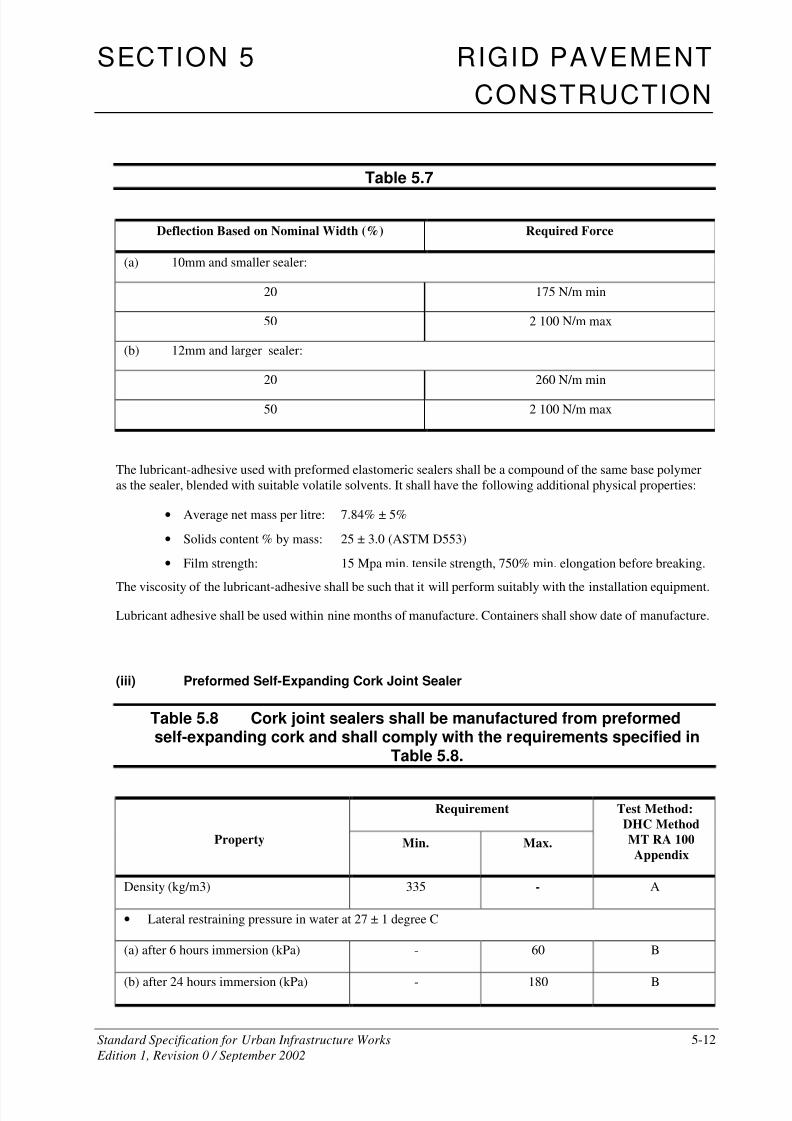
Table 5.7
Deflection Based on Nominal Width (%) Required Force
(a) 10mm and smaller sealer:
20 175 N/m min
50 2 100 N/m max
(b) 12mm and larger sealer:
20 260 N/m min
50 2 100 N/m max
The lubricant-adhesive used with preformed elastomeric sealers shall be a compound of the same base polymer
as the sealer, blended with suitable volatile solvents. It shall have the following additional physical properties:
• Average net mass per litre: 7.84% ± 5%
• Solids content % by mass: 25 ± 3.0 (ASTM D553)
• Film strength: 15 Mpa min. tensile strength, 750% min. elongation before breaking.
The viscosity of the lubricant-adhesive shall be such that it will perform suitably with the installation equipment.
Lubricant adhesive shall be used within nine months of manufacture. Containers shall show date of manufacture.
(iii) Preformed Self-Expanding Cork Joint Sealer
Table 5.8 Cork joint sealers shall be manufactured from preformedself-expanding cork and shall comply with the requirements specified in
Table 5.8.
Requirement
Property Min. Max.
Test Method:
DHC Method
MT RA 100
Appendix
Density (kg/m3) 335 - A
• Lateral restraining pressure in water at 27 ± 1 degree C
(a) after 6 hours immersion (kPa) - 60 B
(b) after 24 hours immersion (kPa) - 180 B
8/2/2019 6503712 Rigid Pavement SS05
http://slidepdf.com/reader/full/6503712-rigid-pavement-ss05 13/49
SECTION 5 RIGID PAVEMENT
CONSTRUCTION
Standard Specification for Urban Infrastructure Works 5-13
Edition 1, Revision 0 / September 2002
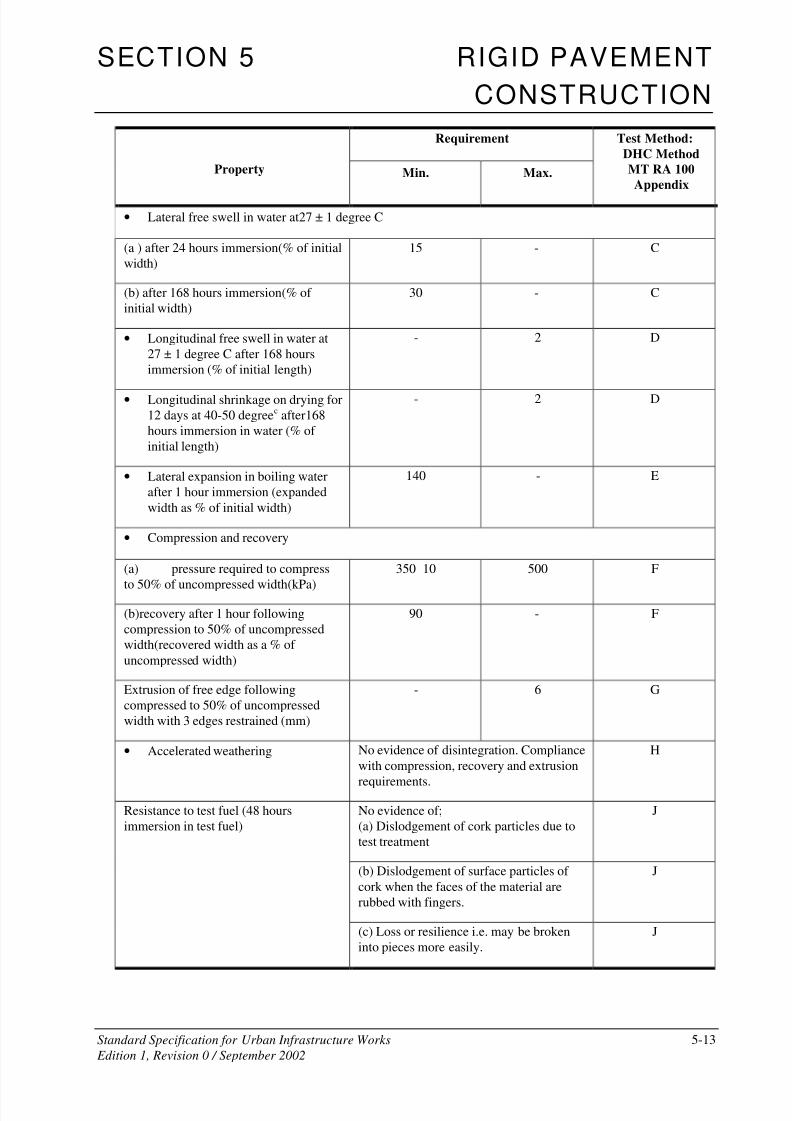
Requirement
Property Min. Max.
Test Method:
DHC Method
MT RA 100
Appendix
• Lateral free swell in water at27 ± 1 degree C
(a ) after 24 hours immersion(% of initial
width) 15 - C
(b) after 168 hours immersion(% of
initial width)
30 - C
• Longitudinal free swell in water at
27 ± 1 degree C after 168 hours
immersion (% of initial length)
- 2 D
• Longitudinal shrinkage on drying for
12 days at 40-50 degreec after168
hours immersion in water (% of
initial length)
- 2 D
• Lateral expansion in boiling water
after 1 hour immersion (expanded
width as % of initial width)
140 - E
• Compression and recovery
(a) pressure required to compress
to 50% of uncompressed width(kPa)
350 10 500 F
(b)recovery after 1 hour following
compression to 50% of uncompressed
width(recovered width as a % of
uncompressed width)
90 - F
Extrusion of free edge following
compressed to 50% of uncompressed
width with 3 edges restrained (mm)
- 6 G
• Accelerated weathering No evidence of disintegration. Compliance
with compression, recovery and extrusion
requirements.
H
No evidence of;
(a) Dislodgement of cork particles due to
test treatment
J
(b) Dislodgement of surface particles of
cork when the faces of the material are
rubbed with fingers.
J
Resistance to test fuel (48 hours
immersion in test fuel)
(c) Loss or resilience i.e. may be broken
into pieces more easily.
J
8/2/2019 6503712 Rigid Pavement SS05
http://slidepdf.com/reader/full/6503712-rigid-pavement-ss05 14/49
SECTION 5 RIGID PAVEMENT
CONSTRUCTION
Standard Specification for Urban Infrastructure Works 5-14
Edition 1, Revision 0 / September 2002
The cork shall be supplied in factory-bonded lengths equal to the width of the paving lane for transverse joints or
4 metres long for longitudinal joints. The top surface of all self-expanding cork shall be taped.
At least two weeks before commencement of concrete placement, submit a sample of the material proposed for
use for approval by the Superintendent. The sample shall comprise fifteen (15) specimens of each widthspecified, each being 11 5mm deep x 11 5mm long and three (3) specimens of each width specified, each being
40mm deep x 900mm long.
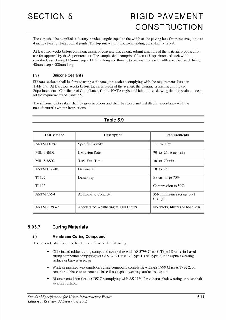
(iv) Silicone Sealants
Silicone sealants shall be formed using a silicone joint sealant complying with the requirements listed in
Table 5.9. At least four weeks before the installation of the sealant, the Contractor shall submit to the
Superintendent a Certificate of Compliance, from a NATA registered laboratory, showing that the sealant meets
all the requirements of Table 5.9.
The silicone joint sealant shall be grey in colour and shall be stored and installed in accordance with the
manufacturer’s written instructions.
Table 5.9
Test Method Description Requirements
ASTM-D-792 Specific Gravity 1.1 to 1.55
MIL-S-8802 Extrusion Rate 90 to 250 g per min
MIL-S-8802 Tack Free Time 30 to 70 min
ASTM D 2240 Durometer 10 to 25
T1192
T1193
Durability Extension to 70%
Compression to 50%
ASTM C794 Adhesion to Concrete 35N minimum average peel
strength
ASTM C 793-7 Accelerated Weathering at 5,000 hours No cracks, blisters or bond loss
5.03.7 Curing Materials
(i) Membrane Curing Compound
The concrete shall be cured by the use of one of the following:
• Chlorinated rubber curing compound complying with AS 3799 Class C Type 1D or resin-based
curing compound complying with AS 3799 Class B, Type 1D or Type 2, if an asphalt wearing
surface or base is used, or
• White pigmented wax emulsion curing compound complying with AS 3799 Class A Type 2, on
concrete subbase or on concrete base if no asphalt wearing surface is used, or
•
Bitumen emulsion Grade CRS170 complying with AS 1160 for either asphalt wearing or no asphaltwearing surface.

8/2/2019 6503712 Rigid Pavement SS05
http://slidepdf.com/reader/full/6503712-rigid-pavement-ss05 15/49
SECTION 5 RIGID PAVEMENT
CONSTRUCTION
Standard Specification for Urban Infrastructure Works 5-15
Edition 1, Revision 0 / September 2002
The Contractor shall submit, for the information of the Superintendent, a current Certificate of Compliance from
an NATA registered laboratory, showing an Efficiency Index of not less than 90 per cent when tested in
accordance with Appendix B of AS 3799.
(ii) Impermeable Blankets
Impermeable blankets shall be:
(a) cotton or hessian backed white opaque polyethylene sheet, or
(b) white opaque polyethylene sheeting, or
(c) other suitable waterproof sheeting
which shall be stitched or cemented together to make blankets of width at least one metre greater than the lane
being placed and not less than 9 metres long.
The blankets shall be free from visible defects, tears and holes and shall comply with the requirements of ASTMC171.
The blankets shall have sufficient strength to meet the required conditions of service and shall be approved
before use.
5.04 EARTHWORKS
Carry out earthworks and preparation of surfaces as specified in Section 2 of this Specification.
Unless otherwise permitted, excavated material shall not be deposited on existing grassed areas.
5.05 CONCRETE SUBBASE
5.05.1 Materials for Concrete Subbase
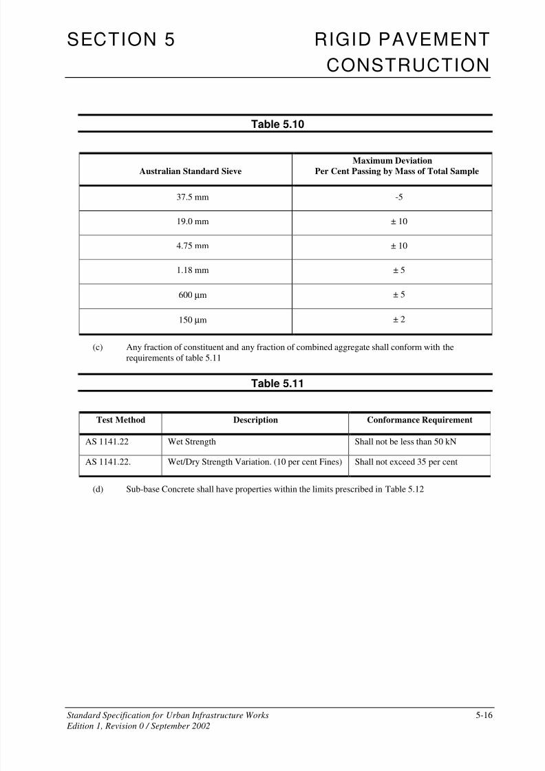
Materials for concrete subbase shall conform to the requirements of Clause 5.03 except that:
(a) Cement shall be Type GP Portland cement or Type GB blended cement complying with AS 3972
(b) The combined grading of aggregate used in the work shall not deviate from the proposed grading by
more than the amounts shown in Table 5.10
8/2/2019 6503712 Rigid Pavement SS05
http://slidepdf.com/reader/full/6503712-rigid-pavement-ss05 16/49
SECTION 5 RIGID PAVEMENT
CONSTRUCTION
Standard Specification for Urban Infrastructure Works 5-16
Edition 1, Revision 0 / September 2002
Table 5.10
Australian Standard Sieve
Maximum Deviation
Per Cent Passing by Mass of Total Sample
37.5 mm -5
19.0 mm ± 10
4.75 mm ± 10
1.18 mm ± 5
600 µm ± 5
150 µm ± 2
(c) Any fraction of constituent and any fraction of combined aggregate shall conform with the
requirements of table 5.11
Table 5.11
Test Method Description Conformance Requirement
AS 1141.22 Wet Strength Shall not be less than 50 kN
AS 1141.22. Wet/Dry Strength Variation. (10 per cent Fines) Shall not exceed 35 per cent
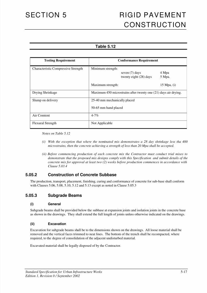
(d) Sub-base Concrete shall have properties within the limits prescribed in Table 5.12
8/2/2019 6503712 Rigid Pavement SS05
http://slidepdf.com/reader/full/6503712-rigid-pavement-ss05 17/49
SECTION 5 RIGID PAVEMENT
CONSTRUCTION
Standard Specification for Urban Infrastructure Works 5-17
Edition 1, Revision 0 / September 2002
Table 5.12
Testing Requirement Conformance Requirement
Characteristic Compressive Strength Minimum strength:
seven (7) days 4 Mpa
twenty eight (28) days 5 Mpa.
Maximum strength: 15 Mpa, (i)
Drying Shrinkage Maximum 450 microstrains after twenty one (21) days air drying.
Slump on delivery 25-40 mm mechanically placed
50-65 mm hand placed
Air Comtent 4-7%
Flexural Strength Not Applicable
Notes on Table 5.12
(i) With the exception that where the nominated mix demonstrates a 28 day shrinkage less tha 400
microstrains, then the concrete achieving a strength of less than 20 Mpa shall be accepted.
(ii) Before commencing production of each concrete mix the Contractor must conduct trial mixes todemonstrate that the proposed mix designs comply with this Specification and submit details of the
concrete mix for approval at least two (2) weeks before production commences in accordance with
Clause 5.03.4
5.05.2 Construction of Concrete Subbase
The production, transport, placement, finishing, curing and conformance of concrete for sub-base shall conform
with Clauses 5.06, 5.08, 5.10, 5.12 and 5.13 except as noted in Clause 5.05.3
5.05.3 Subgrade Beams
(i) GeneralSubgrade beams shall be provided below the subbase at expansion joints and isolation joints in the concrete base
as shown in the drawings. They shall extend the full length of joints unless otherwise indicated on the drawings.
(ii) Excavation
Excavation for subgrade beams shall be to the dimensions shown on the drawings. All loose material shall be
removed and the vertical faces trimmed to neat lines. The bottom of the trench shall be recompacted, where
required, to the degree of consolidation of the adjacent undisturbed material.
Excavated material shall be legally disposed of by the Contractor.
8/2/2019 6503712 Rigid Pavement SS05
http://slidepdf.com/reader/full/6503712-rigid-pavement-ss05 18/49
SECTION 5 RIGID PAVEMENT
CONSTRUCTION
Standard Specification for Urban Infrastructure Works 5-18
Edition 1, Revision 0 / September 2002
(iii) Concrete
Concrete in subgrade beams shall comply with the requirements of the Specification Volume 2 – Concrete
Works. The minimum compressive strength at 28 days shall be 32MPa.
(iv) Steel Reinforcement
Steel reinforcement shall be of the type and size shown on the Drawings and shall be supplied and installed in
accordance with this Specification Part.
(v) Construction and Protection
Subgrade beams shall be constructed before construction of the subbase. The top surface of the subgrade beam
shall be level with the top of the subgrade. Any loose subgrade material shall be recompacted to the correct
level. If the contractor elects to remove any loose material, the voids shall be filled with mortar or concrete and
screeded to provide a surface flush with the top of the subgrade beam and the surrounding subgrade.
A steel float shall be used to produce a smooth surface finish, free of any texture.The subgrade beams shall beprotected from damage by plant, motor vehicles and the paving operation. Any damage shall be made good by
the Contractor. The cost of making good such damage to the subgrade beams shall be borne by the Contractor.
(vi) Curing
The top surface of the subgrade beam shall be cured in accordance with Clause 5.11 before placing the subbase.
(vii) Bond Breaker
The top surface of the subgrade beam shall be treated with a bond breaker which shall consist of a further
application of curing compound neither less than twenty-four hours nor more than seventy two (72) hours before
placing of subbase concrete.
5.05.4 Joints in Concrete Subbase
(a) Transverse construction joints shall:
• be provided only at discontinuities in the placement of concrete determined by the Contractor's
paving operations.
• be constructed normal to the edge line and to the dimensions shown on the Drawings.
• not deviate from a 3m straightedge placed along the joint by more than 10mm.
• be smooth across the joint.
(b) Longitudinal construction joints shall:
• be formed no closer than 300mm of the base longitudinal joints as shown in the Drawings, unless
directed otherwise by the Superintendent.
• not deviate from the plan or nominated position at any point by more than 20mm.
• not deviate from a 3m straightedge placed along the joint by more than 10mm, having made due
allowances for any planned curvature.
• be smooth across the joint.
8/2/2019 6503712 Rigid Pavement SS05
http://slidepdf.com/reader/full/6503712-rigid-pavement-ss05 19/49
SECTION 5 RIGID PAVEMENT
CONSTRUCTION
Standard Specification for Urban Infrastructure Works 5-19
Edition 1, Revision 0 / September 2002
5.05.5 Preparation for placement of Concrete Base
(i) General
Subbase to be covered by concrete base shall be provided with a wax emulsion bond breaker. The wax emulsion
shall comply with AS 3799 Class A Type 2.
Where the pavement base is asphaltic concrete, no bond breaker shall be used. In this case bond is essential and
wax emulsion curing compounds shall not be permitted.
(ii) Preparation of Concrete Sub-base
Concrete subbase with spalled areas shall be treated, as required, prior to application of the bond breaker or
asphaltic concrete.
Immediately prior to any spalled area treatment and the application of bond breaker, the subbase surface shall be
cleaned of all loose, foreign and deleterious material.
Where required, spalled areas shall be treated before the application of the bitumen bond breaker or asphaltic
concrete by infilling with 6:1 sand/cement mortar to provide a surface flush with the surrounding concrete. The
area shall be wetted and sprinkled with neat cement before screeding the mortar into the patches.
A spalled area, if required to be treated, shall have such treatment completed no earlier than five (5) working
days before the application of the bond breaker. Treated spalled areas damaged by the Contractor or others shall
be made good by the Contractor.
The cost of making good treated spalled areas which have been damaged shall be borne by the Contractor.
(iii) Application of Bond Breaker
The wax emulsion used as bond breaker should be the same as used for curing compound. This secondapplication shall be applied at a minimum rate of 0.2 litres per square metre and not earlier than 72 hours before
the placement of the base concrete.
The method of application shall conform to the requirements of Clause 5.11.
(iv) Treatment of Unplanned Cracks
The Superintendent shall direct treatment of unplanned cracks whose width exceeds 0.3mm. This may take the
form of applying an approved 300mm minimum width geotextile backed polymer modified bitumen strip
(reference AUSTROADS Guide to Geotextiles) over the crack prior to placement of the first asphalt base layer
or concrete base, or an extra application of wax emulsion for a width of 300mm along the crack when a concrete
base is required.
The Contractor shall install the Stress Alleviating Membrane strip in accordance with the manufacturer's
instructions.
5.06 FORMWORK
5.06.1 General
Formwork for concrete paving normally shall be fixed boards of suitable material.
Slip-forming of pavement may be carried in accordance with Clause 5.09.4. subject to the availability of suitable
self-propelled slip-form paving equipment and the Contractor's demonstrated ability to carry out placing,finishing and all ancillary operations in accordance with the requirements of this Specification.

8/2/2019 6503712 Rigid Pavement SS05
http://slidepdf.com/reader/full/6503712-rigid-pavement-ss05 20/49
SECTION 5 RIGID PAVEMENT
CONSTRUCTION
Standard Specification for Urban Infrastructure Works 5-20
Edition 1, Revision 0 / September 2002
5.06.2 Fixed Formwork
Forms shall be of steel or seasoned, dressed timber planks fitted with steel angle sections top and bottom,
constructed to finish flush with the face of the form, and covering the full width of the top and bottom of the
forms. Forms shall be free of warps, bends or kinks. The forms shall be staked into position with not less thanthree steel stakes, each not more than 1.5 metres apart, so that the top of the form does not deviate by more than
5mm from the required level. Lock joints between form sections shall be free from play or movement in any
direction. The top surface of the form shall not vary from a straight edge by more than 5mm in 3 metres. The face
of the form shall not vary more than 10mm from a plane surface and, when erected, not more than 3mm from
vertical. Forms shall be equal in depth to the edge thickness of the slab as shown on the drawings. Forms shall be
in one piece for the concrete pavement thickness specified. Forming strips for the keyway of construction joints,
where required, shall be of steel and accurately located on the form face and securely fastened flush against the
face of the forms so that the centre of the key is at the mid-depth of the concrete slab. Forms shall be cleaned and
oiled each time before concrete is to be placed.
Forms shall remain in place at least 12 hours after the concrete has been placed. When conditions on the work are
such that the early strength gain of the concrete is delayed, the forms shall remain in place fora longer period as
directed but not longer than 48 hours.
5.07 REINFORCEMENT, DOWELS AND TIE BARS
Reinforcement shall be formed to the dimensions and shapes shown on the drawings. Reinforcement shall not be
bent or straightened in a manner that will damage the material.
All reinforcement shall be furnished in the lengths indicated on the drawings. Except where shown on the
drawings, splicing of bars shall only be permitted with the approval of the Superintendent as to the location and
method of splicing.
The length of lapped splices not shown on the drawings shall be as follows for unhooked bars:-
Plain bars, Grade 250 - 40 bar diameters
Deformed bars, Grade 400 - 35 bar diameters
Hard-drawn wire - 50 bar diameters
Splices in reinforcing fabric shall be measured as the overlap between the outermost wire in each sheet of fabric
transverse to the direction of splice. This overlap shall not be less than the pitch of the transverse wires plus
25mm.
The reinforcing shall be securely held by blocking from the forms, by supporting on concrete or plastic chairs or
metal hangers, as approved by the Superintendent, and by wiring together where required using annealed iron
wire not less than 1.25 mm diameter. These supports shall be in a regular grid not exceeding 1 m and steel shallnot be supported on metal supports which extend to any surface of the concrete, on wooden supports, nor on
pieces of aggregate. The minimum cover of any bar to the nearest concrete surface shall be 50mm unless
otherwise shown on the drawings.
Place dowels and tie bars across joints where indicated, correctly aligned, and securely held parallel to the
surface of the finished pavement, such that after placement they remain in their specified location.. The spacing
and vertical location of dowels and tie bars shall be as detailed except where the planned spacing cannot be
maintained because of form length or interference with form braces. In such cases, closer spacing with additional
dowels or tie bars shall be used.
Dowels and tie bars shall not be placed through the finished upper surface of the pavement. Dowels and tie bars
shall be placed either ahead of paving or by a bar vibrator into the edge of the joint or by an automatic tie bar
inserter on the mechanical paver. Irrespective of the method of placement, tie bars extending from any side face
8/2/2019 6503712 Rigid Pavement SS05
http://slidepdf.com/reader/full/6503712-rigid-pavement-ss05 21/49
SECTION 5 RIGID PAVEMENT
CONSTRUCTION
Standard Specification for Urban Infrastructure Works 5-21
Edition 1, Revision 0 / September 2002
of base concrete or gutter shall be anchored in a manner which will develop 85 per cent of the yield strength of
the bar in tension
All reinforcement, dowels and tie bars shall be clean and free of oil, grease, loose rust and other foreign material
when the concrete is placed. Paint free portions of dowel S, including ends, with two coats of bituminousemulsion. The unpainted portions of dowels shall be installed in the initially placed concrete slab.
Dowels installed in contraction joints during paving operations shall be held securely in position by means of
rigid metal frame cradles to prevent them from rising, sliding out or becoming distorted under paving operations.
Dowels and tie bars in fixed form paving shall be placed by the bonded-in-place method. Installation by
removing and replacing dowels and tie bars in preformed holes, including their withdrawal to assist in form
stripping, will not be permitted.
Placing and fastening of all reinforcement in the work shall be approved by the Superintendent before concrete is
placed and adequate time shall be allowed for inspections and any corrective work that may be required. Notice
for inspection shall not be less than four working hours before the intended time of commencement of concrete
placement or such time as determined by the Superintendent.
Hold Point 5.3
Process Held: Placement of concrete for paving.
Submission Details: At least four (4) hours prior to commencement of concrete placement for
paving the Contractor shall provide notification that the reinforcement fixing
is completed and ready for inspection.
Release of Hold Point: The Superintendent may inspect the reinforcement, prior to authorising the
release of the Hold Point.
5.08 PRODUCTION, TRANSPORT AND CONSITENCY OFCONCRETE
5.08.1 Production And Handling Of Concrete
At least four weeks before commencing work under this Specification, the Contractor shall submit, for the
information of the Superintendent, details of the proposed methods of handling, storing and batching materials
for concrete, details of proposed mixers and methods of agitation, mixing and transport.
The methods of handling, storing and batching materials for concrete shall be in accordance with AS 1379, with
the following additional requirements:-
(a) Certificates of Calibration issued by a recognised authority shall be made available for inspection by
the Superintendent, as evidence of the accuracy of the scales.
(b) Cementitious material shall be weighed in an individual hopper, with the Portland cement weighed
first.
(c) The moisture content of the aggregates shall be determined at least daily immediately prior to
batching. Corresponding corrections shall be made to the quantities of aggregates and water.

8/2/2019 6503712 Rigid Pavement SS05
http://slidepdf.com/reader/full/6503712-rigid-pavement-ss05 22/49
SECTION 5 RIGID PAVEMENT
CONSTRUCTION
Standard Specification for Urban Infrastructure Works 5-22
Edition 1, Revision 0 / September 2002
Details of proposed mixers and agitation methods shall be in accordance with the plant and equipment sections of
AS 1379, with the additional requirement that in Appendix A of AS 1379 the maximum permissible difference in
slump shall be 10mm.
Hold Point 5.4
Process Held: Production of concrete for concrete paving.
Submission Details: At least twenty (20) working days prior to commencement of concrete paving
the Contractor shall submit details of the proposed methods of handling,
storing and batching materials for concrete, details of proposed mixers and
methods of agitation, mixing and transport.
Release of Hold Point: The Superintendent will review the submitted details, prior to authorising the
release of the Hold Point.
5.08.2 Placing in Fixed Forms
Mixing and transport methods shall be in accordance with the production and delivery sections of AS 1379, with
the following additional requirements:-
(a) The mixer shall be charged in accordance with the manufacturer's instructions.
(b) For the purpose of conducting mixer uniformity tests in accordance with Appendix A of AS 1379 on
a split drum mixer producing centrally mixed concrete, the whole of the batch shall be discharged
into the tray of a moving vehicle. The concrete shall then be sampled from the tray of the vehicle at
points approximately 15 per cent and 85 per cent along the length of the tray.
(c) For truck-mixed concrete, addition of water in accordance with the batch production section of
AS 1379 shall be permitted only within ten minutes of completion of batching and within 200m of
the batching facilities. The delivery docket must clearly indicate the amount of water added, but in
no circumstance shall the water : cement ratio be exceeded. Mixing of the concrete shall be
completed at that location.
(d) Admixtures shall be separately prediluted with mixing water and shall be incorporated by a method
which ensures that no adverse interaction occurs.
(e) After addition of the cement to the aggregate, concrete shall be incorporated into the work within:-
- One and a half hours, where transported by truck mixer or agitator;
- One hour, where transported by non-agitating trucks.
Means of verification, satisfactory to the Superintendent, of the times of addition of cement to the
aggregate shall be provided. The times within which the concrete shall be incorporated into the
work may be reduced if the Superintendent considers the prevailing weather, mix type, or materials
being used warrant such a change.
(f) The size of the batch in an agitator vehicle shall not exceed the manufacturer's rated capacity nor
shall it exceed 80 per cent of the gross volume of the drum of the mixer.

8/2/2019 6503712 Rigid Pavement SS05
http://slidepdf.com/reader/full/6503712-rigid-pavement-ss05 23/49
SECTION 5 RIGID PAVEMENT
CONSTRUCTION
Standard Specification for Urban Infrastructure Works 5-23
Edition 1, Revision 0 / September 2002
5.08.3 Mixing Time
Minimum mixing time will be as determined for the approved mix and verified when the trial section is
constructed.
Where by reason of delay, it is necessary to hold a batch in the mixer, mixing may be continued for a maximum
of ten minutes except for split drum mixers where the maximum shall be five minutes.
For longer periods, the batch may be held in the mixer and turned over at regular intervals, subject to the time
limits specified for incorporation of the concrete into the work not being exceeded.
5.08.4 Consistency
At all times between mixing and discharge, the slump shall be within the range specified for the nominated mix
mechanically placed or hand placed concrete.
The consistency of the concrete shall be checked by use of a slump cone in accordance with AS 1012.3.1. The
test shall be made on concrete samples obtained in accordance with AS 1012.1.
The consistency of the concrete shall be checked within 30 minutes of adding cement to the aggregate. If the
actual haul time exceeds 45 minutes, the consistency shall also be checked immediately prior to discharge.
Concrete which is non-conforming in relation to consistency shall not be incorporated into the work. Check tests
shall be done on each truck load of concrete. The cost of consistency testing shall be borne by the Contractor.
Check tests shall be done on each truckload of concrete.
5.09 PLACING AND FINISHING
General
At least four weeks before commencing work under this Specification, the Contractor shall submit as part of the
Quality Plan, for the information of the Superintendent, full details of the equipment and methods proposed for
placing and finishing the concrete base and sub-base together with a paving plan showing proposed paving
widths, sequence, joint details and estimated daily outputs.
Hold Point 5.5
Process Held: Placement of concrete paving.
Submission Details: At least twenty (20) working days prior to commencement of concrete paving
the Contractor shall submit details of the equipment and methods proposedfor placing and finishing the concrete base and subbase .
Release of Hold Point: The Superintendent will review the submitted details, prior to authorising the
release of the Hold Point.
When placing concrete subbase the subgrade shall be wetted down sufficiently in advance of placing to ensure a
firm, uniformly moist surface at the time of placing.
When placing concrete base the subbase shall be wetted down sufficiently in advance of placing to ensure a firm,
uniformly moist surface at the time of placing. Remove loose sand from bituminous emulsion curing seals. Where
concrete subbase is used the subbase surface shall be clean and free of loose or foreign matter and prepared inaccordance with Clause 5.05.3 (iii)
8/2/2019 6503712 Rigid Pavement SS05
http://slidepdf.com/reader/full/6503712-rigid-pavement-ss05 24/49
SECTION 5 RIGID PAVEMENT
CONSTRUCTION
Standard Specification for Urban Infrastructure Works 5-24
Edition 1, Revision 0 / September 2002
Construction equipment shall not operate on the prepared subbase after approval to place concrete has been
given.
Unless otherwise approved, placement at each placing location shall proceed at a rate of not less than 25 linear
metres per hour.
Concrete shall be placed within one hour of the time of batching and before it has attained initial set. The
temperature of the concrete when deposited in the forms shall be not less than l0°C nor more than 32°C. Concrete
shall not be placed either during rain or when the air temperature in the shade is below 5°C or above 38°C.
Deposit concrete in such a manner as to require a minimum of rehandling. The placing of concrete shall be rapid
and continuous between transverse construction joints.
5.09.1 Trial Section
The Superintendent may require the construction of a trial section of area up to 100m2 to ensure that equipment,
crews and techniques are adequate to construct work of the specified standard. This section shall be constructed
so that it may be incorporated in the finished work.
The trial section shall be constructed using the same materials, concrete mix, equipment and methods the
Contractor intends to use for the remaining work. The Contractor shall demonstrate the methods proposed to be
used for texturing, the application of curing compound, the construction and sawing of joints and the placement
of tie bars and dowels.
The trial shall also be used to demonstrate that the Contractor's allowances for concrete strength, compaction and
slab thickness are adequate to achieve the minimum requirements specified.
Unless advised by the Superintendent of any deficiencies in the trial section, due to failure to comply with this
Specification, the Contractor may proceed with placing concrete base from a time ten working days after the
completion of the trial concrete base or such earlier time as the Superintendent may allow. In the event of
deficiencies in the trial concrete base, the Superintendent may order the Contractor to construct a further lengthof trial concrete base which shall be treated as the first. If, after three trials, the base still is deficient in some way,
the Superintendent may require the Contractor to justify to the satisfaction of the Superintendent why the work
should be allowed to continue using that method and/or equipment and/or materials and/or personnel.
The Superintendent shall have the right to call for a new trial section at any stage of work under the contract
when changes by the Contractor in the equipment, materials, mix, plant or rate of paving are deemed by the
Superintendent to warrant such procedure or when concrete as placed does not comply with this Specification.
Trial concrete, which does not comply with the Specification, shall be rejected by the Superintendent and shall be
removed by the Contractor.
5.09.2 Placing in Fixed Forms – Hand Placing
(i) Spreading
Place concrete so that the face is generally vertical, and normal to the direction of placing. Concrete shall be
placed uniformly over the width of the slab or lane and, in such manner as to minimise segregation. All hand
spreading of concrete shall be done with shovels, not rakes.
Where an interruption to placing occurs, which is likely to result in a non-monolithic concrete mass, the
Contractor shall form a transverse construction joint in accordance with Clause 5.10
Should subsequent testing at the location of an interruption indicate the presence of non-monolithic concrete,
such concrete shall be removed and replaced in accordance with Clause 5.14.6
8/2/2019 6503712 Rigid Pavement SS05
http://slidepdf.com/reader/full/6503712-rigid-pavement-ss05 25/49
SECTION 5 RIGID PAVEMENT
CONSTRUCTION
Standard Specification for Urban Infrastructure Works 5-25
Edition 1, Revision 0 / September 2002
(ii) Vibration
All concrete, including that adjacent to forms or existing concrete, shall be compacted by internal mechanical
vibration.
The vibrators shall be capable of transmitting at least 5000 impulses per minute when under load and the
vibration shall be of sufficient amplitude to produce noticeable vibrations at 300mm in radius. The number of
vibrators on site in full working order shall be not less than 1 per 7 cubic metres of concrete placed per hour.
The vibrators shall be inserted into the concrete to such depth as will provide the best compaction, but not deeper
than 50mm above the surface of the subbase. The duration of vibration shall be sufficient to produce satisfactory
compaction, but not longer than 30 seconds in any one location.
Vibrators shall not be used for distributing and spreading concrete.
(iii) Finishing
(a) General
Finishing operations shall be started immediately after placement, spreading and compaction of the
plastic concrete.
Finishing operations shall comprise transverse finishing, longitudinal straight-edge finishing and
texturing of the surface, in that order, and shall be started immediately after placing of the concrete
and completed as soon as possible and prior to the concrete attaining initial set.
(b) Transverse Finishing
Transverse finishing shall be by mechanical screed. Vibrating screeds shall have twin beams, be at
least 300mm longer than the width of lane being finished and be equipped with handles. The screed
edge shall be at least 100mm wide. Alternatively a counter rotating tube screed of suitable design
may be used.
Strike off concrete and screed to form levels as soon as possible after vibration. At least two passes
shall be made with the screed over each section of pavement.
(c) Straight-edge Finishing
After the transverse finishing is completed, but while the concrete is still plastic, minor irregularities
and score marks in the pavement surface, particularly across formed contraction joints, shall be
eliminated by means of hand-operated long-handled aluminium floats.
(d) Surface Texturing
When most of the water glaze or sheen has disappeared and before the concrete becomes
non-plastic, the whole surface of the pavement shall be textured by use of a fine broom or
hessian-drag. The Contractor shall submit to the Superintendent details of the proposed texturing
method and equipment.
The average texture depth of the finished surface shall be in the range 2.0 -2.5 mm.
5.09.3 Slip-Form Placement – Mechanical Paving
(i) Spreading
The mechanical paver shall be self propelled and shall be so designed and operated as to place the plastic
concrete as it leaves the machine in a uniform layer over the width of the slab being placed.
8/2/2019 6503712 Rigid Pavement SS05
http://slidepdf.com/reader/full/6503712-rigid-pavement-ss05 26/49
SECTION 5 RIGID PAVEMENT
CONSTRUCTION
Standard Specification for Urban Infrastructure Works 5-26
Edition 1, Revision 0 / September 2002
When the mechanical paver rides on the edge of previously constructed concrete, take precautions to prevent
damage to the surface and edge of the existing concrete.
The mechanical paver shall have a gross operating mass of not less than 4 tonnes per lineal metre of paved width.
It shall be capable of paving at a speed of one metre per minute or less as required to enable the continuousoperation of the paver and obtain the required degree of compaction. It shall include the following features:-
(a) An automatic control system with a sensing device to control line and level to the specified
tolerances.
(b) Means of spreading the mix uniformly and regulating the flow of mix to the vibrators without
segregation of the components.
(c) Internal vibrators capable of compacting the full depth of the concrete.
(d) Adjustable extrusion screed and/or conforming plate to form the slab profile and produce the
required finish on all surfaces.
(e) Capability of paving in the slab widths or combination of slab widths and slab depths shown on the
Drawings.
Once spreading commences, the concrete paving operation shall be continuous. The mechanical paver shall be
operated so that its forward progress shall not be stopped due to lack of concrete. If disruptions occur for any
reason, the Superintendent may direct that a construction joint be formed before the recommencement of paving
operations. The cost of forming such construction joint shall be borne by the Contractor.
(ii) Vibration
Should subsequent testing at the location of an interruption indicate the presence of non-monolithic concrete,
such concrete shall be removed and replaced in accordance with Clauses 5.14.6
Vibrating equipment used in compacting the concrete shall be of a suitable type with vibrating beam or beams of
adequate power to fully compact the whole depth of the concrete.
The concrete slabs shall present a uniform dense appearance. If honey-combing or other areas deficient in fines
are present then surface vibration shall be supplemented in subsequent operations by the use of immersion type
vibrators inserted adjacent to the edge of the slab being placed.
(iii) Finishing
The paving machine shall be equipped with finishing devices which shall be capable of producing a surface finish
of equal quality and texture to that specified above for paving cast between forms. Remove minor irregularities
using long handled aluminium floats as specified earlier.
Texturing of the concrete surface may be effected by use of a fine broom or hessian-drag. The Contractor shall
submit to the Superintendent details of the proposed texturing method and equipment. The average texture depth
of the finished surface shall be in the range 2.0 -2.5 mm.
5.09.4 Rate of Evaporation
When the value of Rate of Evaporation, determined from the graph in Figure 5.1, exceeds 0.50 kilograms per
square metre per hour the Contractor shall take precautionary measures satisfactory to the Superintendent for the
prevention of excessive moisture loss. If, in the opinion of the Superintendent, such precautionary measures
prove to be unsatisfactory, the Contractor shall cease work while the evaporation rate is in excess of 0.50
kilograms per square metre per hour.
Should the Contractor elect to use an evaporation retarder to prevent excessive moisture loss, application shall be
by fine spray after all finishing operations, except minor manual bull-floating, are complete.
8/2/2019 6503712 Rigid Pavement SS05
http://slidepdf.com/reader/full/6503712-rigid-pavement-ss05 27/49
SECTION 5 RIGID PAVEMENT
CONSTRUCTION
Standard Specification for Urban Infrastructure Works 5-27
Edition 1, Revision 0 / September 2002
The Contractor shall be responsible for measuring and recording concrete temperature and wind velocity at the
point of concrete placement, and for continuously measuring and recording air temperature and relative humidity
at the site throughout the course of the work. The Contractor shall provide and maintain all equipment and shall
provide suitable personnel necessary for all such measuring and recording.
The cost of providing and maintaining such equipment, providing suitable personnel and taking precautionary
measures for the prevention of excessive moisture loss shall be borne by the Contractor.
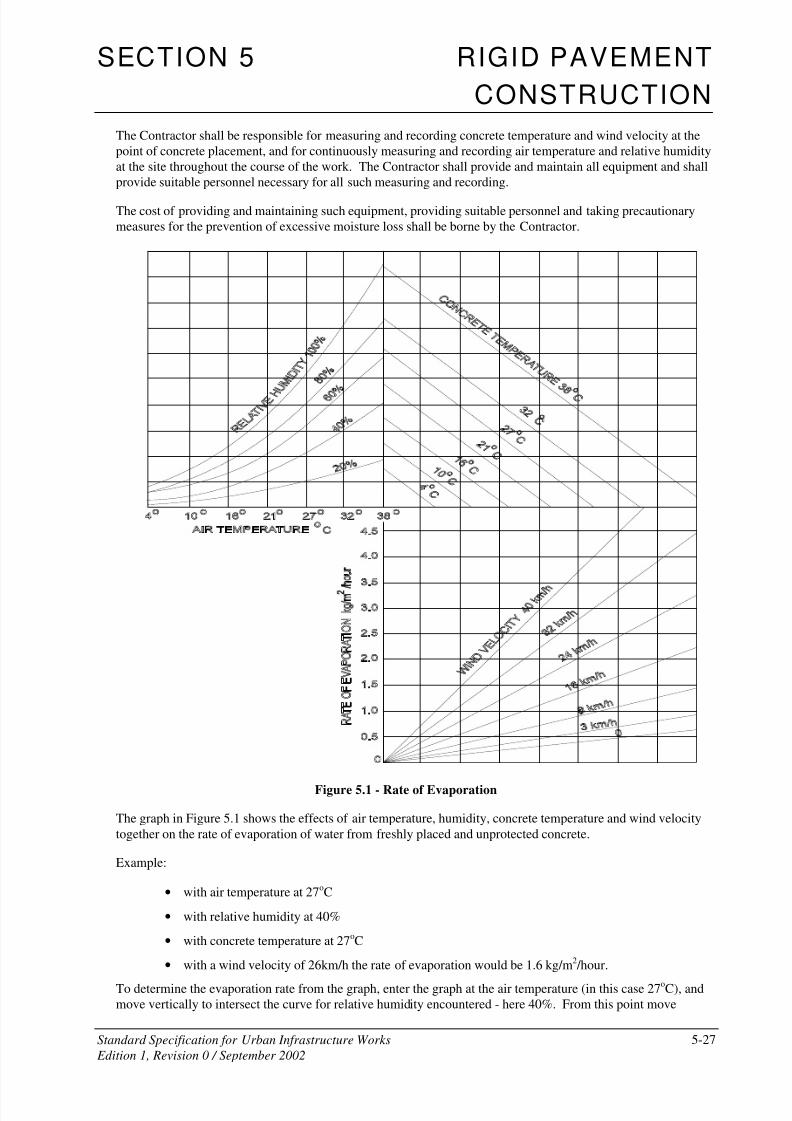
Figure 5.1 - Rate of Evaporation
The graph in Figure 5.1 shows the effects of air temperature, humidity, concrete temperature and wind velocity
together on the rate of evaporation of water from freshly placed and unprotected concrete.
Example:
• with air temperature at 27oC
• with relative humidity at 40%
• with concrete temperature at 27oC
• with a wind velocity of 26km/h the rate of evaporation would be 1.6 kg/m2 /hour.
To determine the evaporation rate from the graph, enter the graph at the air temperature (in this case 27oC), and
move vertically to intersect the curve for relative humidity encountered - here 40%. From this point move
8/2/2019 6503712 Rigid Pavement SS05
http://slidepdf.com/reader/full/6503712-rigid-pavement-ss05 28/49
SECTION 5 RIGID PAVEMENT
CONSTRUCTION
Standard Specification for Urban Infrastructure Works 5-28
Edition 1, Revision 0 / September 2002
horizontally to the respective line for concrete temperature - here 27oC. Move vertically down to the respective
wind velocity curve - in this case interpolating for 26km per hour - and then horizontally to the left to intersect
the scale for the rate of evaporation.
5.09.5 Slab Anchors
(i) General
Slab anchors shall be constructed normal to the control line, to the dimensions and at the locations shown on the
Drawings.
Slab anchors shall extend over the full width of the base and the associated transverse expansion joint shall not be
placed closer than 2m to other transverse joints. Where necessary, the Superintendent shall authorise a change in
the spacing of transverse contraction joints to ensure that this minimum clearance is obtained.
(ii) Excavation
Excavation of trenches for slab anchors shall be to the dimensions and details shown on the drawings.
All loose material shall be removed and the vertical faces trimmed to neat lines. The bottom of the trench shall
be recompacted, where required, to the degree of consolidation of the adjacent undisturbed material.
The Contractor shall dispose of excavated material at locations approved by the Superintendent.
Where a slab anchor is required at the junction of an existing flexible pavement, a straight sawcut to the full
depth of the asphaltic concrete or bituminous seal shall be made in the flexible pavement along the joint line.
Excavation of the trench shall then take place as described above without disturbance or damage to the existing
flexible pavement. Any disturbance or damage to the flexible pavement shall be made good as directed by the
Superintendent.
The cost of making good any disturbance or damage to the flexible pavement shall be borne by the Contractor.
(iii) Concrete
Concrete for slab anchors shall be produced, transported and placed in accordance with the requirements for
hand-placed concrete base.
Slab anchors shall be poured separately from the base slabs to the dimensions and details shown on the drawings
up to the top surface of the subbase.
A transverse isolation joint shall be provided on the downhill side of the slab anchor.
Steel reinforcement in slab anchors shall be of the type and size shown on the drawings and shall be supplied and
fixed in accordance with this Specification.
Bridge approach slabs, if not in the bridge contract, shall be constructed at bridge abutments to the dimensions
and details shown on the drawings and in accordance with the requirements for concrete base.
5.10 JOINTS IN CONCRETE BASE
5.10.1 General
Joints shall be constructed and located as detailed on the drawings. Joints shall be straight and plumb. Unless
otherwise detailed on the drawings transverse expansion and contraction joints shall be normal to the longitudinal
joints, and continuous from edge to edge of the pavement throughout all paving slabs that are connected in asingle paved area.
8/2/2019 6503712 Rigid Pavement SS05
http://slidepdf.com/reader/full/6503712-rigid-pavement-ss05 29/49
SECTION 5 RIGID PAVEMENT
CONSTRUCTION
Standard Specification for Urban Infrastructure Works 5-29
Edition 1, Revision 0 / September 2002
Where kerbs are cast as part of the paving slab, joints of the same type shall continue through the kerb sections
on the same alignment as those in the paving slab.
5.10.2 Construction Joints(i) Longitudinal Construction joints
(a) Types of Joint
Longitudinal joints shall be provided at the locations shown on the drawings or where directed by
the Superintendent. The joints shall be parallel to the control line and/or to the dimensions and
details shown on the drawings.
Longitudinal joints shall be formed or induced either by sawing or by machine insertion of a crack
inducer ribbon.
The line of longitudinal tied joints shall not deviate from the designed position at any point by more
than 10mm. The line shall also not deviate from a 3m straightedge by more than 10mm having madedue allowance for any planned curvature.
Where the longitudinal tied joint is formed or slipformed, the joint face shall be corrugated in
accordance with the details shown on the drawings.
Where required joint sealer shall be silicone sealant, preformed elastomeric strips or preformed self
expanding cork strips as detailed.
Tied construction joints shall be provided with tie bars as detailed and in accordance with Clause
5.07. Unless otherwise detailed, omit grooves and joint sealers in tied construction joints.
Where the multi-lane width is greater than 18m, a longitudinal isolation joint shall be constructed at
each location shown on the Drawings and in accordance with Clause 5.10.2(i) (e).
(b) Formed Joints
Construction grooves for sealer (where required) in formed joints shall be centred on the face of the
joint.
When forming the edge of the first placed slab, cast in a step recess of width equal to half the
nominal width of scaler groove and of depth equal to the depth of joint scaler + 5mm. The step
recess shall be formed by fixing a metal strip of appropriate dimensions to the top of the form such
as to leave a clean straight edge in the concrete when the form is stripped.
After stripping and when concrete has cured sufficiently, clean arrises of step recesses using a rotary
concrete saw.
Prior to placement of concrete adjacent to previously formed slab edges, fix an inert form strip such
as "Caneite" or polystyrene foam to the edge using a suitable waterproof adhesive. Do not place
concrete until the adhesive has set.
(c) Sawn Joints
Grooves for scaler in sawn construction joints shall be centred on the face of the joint.
Carry out grooving and sealing operations as specified in Clause 5.10.4 (ii) for sawn contraction
joints.
8/2/2019 6503712 Rigid Pavement SS05
http://slidepdf.com/reader/full/6503712-rigid-pavement-ss05 30/49
SECTION 5 RIGID PAVEMENT
CONSTRUCTION
Standard Specification for Urban Infrastructure Works 5-30
Edition 1, Revision 0 / September 2002
(d) Ribbon-Induced Joints
Ribbon-induced longitudinal tied joints shall be provided to the dimensions and details shown on the
drawings. The inducer ribbon shall be machine-inserted so that the top of the ribbon does not
protrude above the surface of the base, nor shall it lie below the surface of the base by more than3mm.
The inducer ribbon shall be a minimum of 0.5mm thick. When placed, it shall be within 5o
of the
vertical plane. Inducer ribbon which curls on placement and when cut in the base is found to be
curved in transverse section by more than 3mm from straight shall be rejected.
At transverse construction joints, the inducer ribbon shall be carried through the joint sufficiently to
allow a connection by strong stapling, or other method approved by the Superintendent, to the
inducer ribbon to be used on the other side of the joint. When a join is necessary in the inducer
ribbon during paving, the inducer ribbon on the new spool shall be similarly joined to the tail of the
inducer ribbon on the old spool.
(e) Longitudinal Isolation Joints
Longitudinal isolation joints shall be provided where shown on the drawings and where directed by
the Superintendent.
The line of the longitudinal isolation joint shall not deviate from the specified position by more than
10mm. The line of the joint shall not deviate from a 3m straightedge by more than 10mm.
The joint filler shall consist of preformed jointing material of bituminous fibreboard and the joint
sealant shall comply with the silicone sealant requirements of Clause. They shall be installed in
accordance with the drawings and in a manner conforming to the manufacturer's recommendations
except that reference to backer rods shall not apply.
(ii) Transverse Construction Joints
Transverse construction joints shall be installed at the end of each day's placing operations and at any other
points within a paving lane when concrete placement is interrupted for 30 minutes or longer.
Transverse construction joints at the end of each day's placing operation shall be installed in the location of a
planned transverse contraction or expansion joint. Transverse construction joints located at planned transverse
contraction joints shall be of the same type as the dowelled transverse joints.
When concrete placement is interrupted for 30 minutes or longer, or cannot be continued due to equipment
failure or adverse weather conditions, a transverse construction joint may be installed within the slab unit, but
only within the middle third of the length of the slab between planned joints. Excess concrete shall be removed.
When a construction joint is installed within a concrete slab unit the joint shall, unless otherwise detailed, be a
keyed and tied construction joint. A transverse construction joint within a concrete slab unit shall not be providedwith a groove at the surface of the concrete.
5.10.3 Expansion Joints
Form expansion joints around structures and features which project through, into or against the pavement and at
other locations as detailed. Joint filler shall be of the type and thickness indicated and be installed so as to form a
complete uniform separation of materials on either side of the joint.
Where other joints in the paving are sealed with preformed, self-expanding cork, the expansion joint filler shall
be a full depth strip of the same material.
8/2/2019 6503712 Rigid Pavement SS05
http://slidepdf.com/reader/full/6503712-rigid-pavement-ss05 31/49
SECTION 5 RIGID PAVEMENT
CONSTRUCTION
Standard Specification for Urban Infrastructure Works 5-31
Edition 1, Revision 0 / September 2002
Where other joints in the paving are sealed with preformed elastomeric strips, expansion joints shall be formed
by fixing an inset form strip such as "Caneite" or polystyrene foam to the edge of the hardened slab. The strip
shall extend for the full depth of the slab and be of thickness equal to the nominal width of the joint. It shall be in
two parts with the top part equal in depth to the seal groove shown on the drawing. The strip shall be fixed with a
suitable waterproof adhesive. Do not place concrete until the adhesive has set. When concrete has hardenedsufficiently, remove top section of former strip and insert sealer as specified in Clause 5.10.4 for contraction
joints.
5.10.4 Contraction Joints
(i) Types of Joint
Transverse contraction joints in paving cast between fixed forms shall be sawn, induced and/or formed as
detailed.
Transverse contraction joints in slip-formed paving shall be sawn.
Transverse contraction joints shall be constructed normal to the control line and to the dimensions and detailsshown on the Drawings. Where necessary, the joint may be skewed to a maximum 1 in 12 to accommodate
construction joints and slab anchors.
(ii) Sawn Contraction Joints
Sawn contraction joints shall be constructed by cutting a groove in the hardened concrete. Sawing operations
shall be carried out as required during the day or night regardless of weather conditions. If uncontrolled cracking
of concrete occurs, concrete placing shall be suspended.
Provide one standby sawing machine for every machine planned for use.
Saw cuts shall be at least 45mm deep or such greater depth as is detailed on the drawings and of uniform width in
the range 3-5mm for the full depth of the cut. The line of the transverse contraction joint shall be without anydiscontinuities. No edge shall deviate from a 3m straight edge by more than 10mm.
The surface of the transverse contraction joint shall not exhibit more than 5mm of vertical or horizontal edge
ravelling. The length of edge ravelling shall not be more than 300mm in any 1 m length of joint on each edge.
Saw debris shall be washed from the joint and pavement immediately after sawing.
The time of sawing shall be varied between 6 and 24 hours after initial paving, depending on existing and
anticipated weather conditions, and shall be such as to prevent uncontrolled cracking of the pavement. Sawing of
the joints shall commence as early as possible, commensurate with the concrete having hardened sufficiently to
permit cutting the concrete without excessive chipping, spalling or tearing. The sawn faces or joints will be
inspected for undercutting or washing of the concrete due to early sawing. If this action is sufficiently deep to
cause structural weakness or excessive cleaning difficulty, the sawing operation shall be delayed, and resumed as
soon as the sawing can be continued without damaging the concrete slab. Nevertheless, all sawing will becompleted not later than 24 hours after placement of the concrete. The joints shall be sawn, if the concrete is
sufficiently hard, in the sequence of the concrete placement, initially at every fourth joint, then at the intermediate
intervals.
Before sawing a joint, the concrete shall be examined closely for cracks, and the joint shall not be sawn if a crack
has occurred near the location chosen for a joint. Discontinue sawing if a crack develops ahead of the saw cut.
Immediately after each joint is sawn, the saw cut and adjacent concrete surface shall be thoroughly flushed with
water until all waste from sawing is removed from the joint, and the joint caulked with plastic or rubber tubing or
suitable "Tee" shaped extrusion which will remain in place and prevent the entry of foreign material into the
joint.
8/2/2019 6503712 Rigid Pavement SS05
http://slidepdf.com/reader/full/6503712-rigid-pavement-ss05 32/49
SECTION 5 RIGID PAVEMENT
CONSTRUCTION
Standard Specification for Urban Infrastructure Works 5-32
Edition 1, Revision 0 / September 2002
(iii) Cleaning and Temporary Sealing
Immediately after any sawing, the sawcut shall be cleaned of all debris. The cleaning method used shall not
damage the sawcut nor leave any substance deleterious to the concrete or to the adhesion of the joint sealants to
be used. The method shall incorporate a pressurised liquid or liquid/air jet. Cleaning liquid shall not be gravityfed from tanks.
Immediately after cleaning the joint shall be temporarily sealed by a continuous closed-cell polyethylene backer
rod of diameter shown on the drawings or as required by the Superintendent.
The top of the sealant shall be neither higher than nor more than 10 mm below the concrete surface. The backer
rod shall pass over any longitudinal joint seal already in place.
The temporary sealant shall be maintained by the Contractor until the joint is sealed permanently. Damaged or
disturbed temporary sealants shall be removed, the transverse contraction joint recleaned to the satisfaction of the
Superintendent and a new temporary sealant inserted.
(iv) Formed Contraction Joints
(a) Types
Formed transverse contraction joints shall be constructed by formation of a weakened plane in the
plastic concrete. This may be achieved by the insertion of a preformed cork sealer during placing
and finishing or by the insertion of a crack inducer during placing and the subsequent insertion of a
preformed elastomeric sealer.
(b) Crack Induction
Crack inducers shall be of suitable material and of dimensions shown on the drawings. Details shall
be submitted for approval before use. They shall comprise a permanent section which remains in the
completed joint and a removable top section. Insert the crack inducer so that the top of theremovable section finishes flush with the surface of the concrete.
(c) Cork Sealed Joints
The depth of preformed cork sealer shall be at least equal to the depth of joint shown on the
drawings. Protect cork from exposure to moisture at all times until it is incorporated into joints. Do
not soak before installation.
Unless otherwise approved, equipment for installing sealers shall be a machine equipped with a
vibratory cutting and installing bar for cutting a vertical groove in the plastic concrete at the
prescribed joint location and, preferably simultaneously, installing the sealer to the required depth
throughout the full width of the paving lane. The vibration units of the cutting and installing bar or
bars shall be so arranged that the vibration will be uniformly distributed throughout the bar. Theintensity of vibration shall be adjustable as required to form a groove of correct size for the sealer,
and for compacting the concrete around the in-place sealer. The cutting and installing bar shall be
either hydraulically assisted or of sufficient mass to form the groove in conjunction with the
vibration units.
Submit details of contraction joint forming equipment for approval before commencing placing
operations.
Insert the joint sealer in the plastic concrete immediately following final finishing. Adjacent sections
of joint sealer within each slab unit shall be securely joined by suitable adhesives or fasteners so that
the sealer is continuous from edge to edge of the pavement lane.
Compact concrete adjacent to the sealer using a vibrating plate float.
8/2/2019 6503712 Rigid Pavement SS05
http://slidepdf.com/reader/full/6503712-rigid-pavement-ss05 33/49
SECTION 5 RIGID PAVEMENT
CONSTRUCTION
Standard Specification for Urban Infrastructure Works 5-33
Edition 1, Revision 0 / September 2002
On completion, the top of the sealer shall be between 0 and 5mm below the finished surface of the
adjacent concrete. Remove tape from top of sealer when concrete has attained final set.
5.10.5 Grooving and Sealing(i) Sawn Joint Grooves
After the expiration of the curing period and immediately prior to joint sealing operations, saw a groove for joint
sealer in the top of sawn contraction and construction joints. Grooves shall be straight and parallel sided. Unless
otherwise approved, cut grooves during daylight hours. The concrete temperature at the time of saw cutting shall
be not less than 10°C.
Where cracks have formed below initial saw cuts, increase the width of sawn groove by an amount equal to the
width of the crack. Provide a range of saw blade thicknesses to facilitate these adjustments. No additional
payment will be made for adjustments to groove widths.
(ii) Formed Joint GroovesRemove inert former strips from formed grooves to the depth necessary to accommodate sealers.
(iii) Preparation of Joints
Immediately before the installation of the sealer, the joints shall be cleaned thoroughly until all laitance, curing
compound, filler and protrusions of hardened concrete are removed from the sides and upper edges so that the
entire joint space is free from concrete, dirt, dust and other objectionable materials.
After the grooving operation, all foreign and loosened material shall be blown from the joint by compressed air
and high pressure water jet.
(iv) Installation of Preformed Elastomeric SealerAdopt the following procedure for the installation of preformed elastomeric joint sealer:
• The prepared grooves shall be clean and dry at the time of installation.
• Immediately prior to the insertion of the joint sealer within the groove, apply a bead of
elastomer-based lubricant/adhesive to the top edge of each side of the joint.
• When installing the joint sealer into the groove, use a suitable roller to ease the sealer into the
groove.
• The joint sealer shall be set 4-6 mm below the finished concrete pavement surface.
(v) Installation of Preformed Cork Sealer
At the time of installation of preformed self-expanding cork joint sealer, the concrete in the vicinity of joints shall
be surface dry and the pavement surface temperature shall be in the range 2°C to 30°C.
The factory bonded lengths of joint sealer shall be joined together to provide a continuous run of joint sealer
within the groove for the full length of the slab. Lengths of joint sealer to be joined shall be mitred and glued
using suitable waterproof adhesive.
Adopt the following procedure for the installation of preformed cork sealer in formed construction joints.
• The prepared grooves shall be clean and dry at the time of installation.
• The joint sealer shall be installed as a loose fit within the groove.
• Immediately prior to the insertion of the’ joint sealer within the groove, coat the full area of one sideof the joint sealer with a suitable
8/2/2019 6503712 Rigid Pavement SS05
http://slidepdf.com/reader/full/6503712-rigid-pavement-ss05 34/49
SECTION 5 RIGID PAVEMENT
CONSTRUCTION
Standard Specification for Urban Infrastructure Works 5-34
Edition 1, Revision 0 / September 2002
• waterproof adhesive.
• When installing the joint sealer into the groove, apply pressure with a suitable tool over lengths of
not less than 30Omm to ease the sealer into the groove.
• Following insertion into the groove, press the sealer firmly against the groove wall on the side wherethe adhesive has been applied by inserting a thin metal plate beside the joint sealer and levering
lightly.
• The joint sealer shall be set flush + 0mm -5mm with the finished concrete pavement surface.
• At least 24 hours after installation, remove the protective tape from the top surface of the joint
sealer.
• At least 24 hours, but not more than 48 hours after installation, water the installed joint sealers
thoroughly. Repeat daily for five days or until the cork has expanded to fill the grooves completely.
(vi) Installation of Silicone Sealer
Installation of a silicone sealant shall take place only when the side walls of the groove have been grit blasted andare surface dry.
Immediately before introducing the silicone sealant into the groove, any foreign or disturbed material shall be
cleaned from the joint and from the top of the backer rod by dry air jet. The backer rod shall then be depressed
to the depth such that the bottom of the silicone sealant shall be at the planned location and of the correct shape.
If the backer rod is damaged in any way it shall be replaced for the full length of the joint.
The method to be used for permanent sealing with silicone sealant shall be approved by the Superintendent
before permanent sealing commences. Notwithstanding any approval given by the Superintendent to a proposed
method, the Contractor shall be responsible for producing a permanent seal complying with all requirements of
this Specification.
5.11 CURING AND PROTECTION
5.11.1 General
Protect green concrete from rain and flowing water.
Concrete shall be cured by protection against loss of moisture and rapid temperature changes for a period of not
less than 7 days from the completion of the finished operations. Curing shall comprise:
• membrane curing; or
• initial curing followed by moist curing and impermeable blanket curing.
If membrane curing is delayed for any reason, then initial curing procedures shall be carried out until the
membrane can be applied.
Failure to maintain saturated conditions on the concrete pavement during initial curing, failure to provide
sufficient membrane curing compound and/or curing blankets, lack of adequate water for both curing and other
requirements, or other failures to comply with curing requirements shall be cause for immediate suspension of
concreting operations.
Provide protection as necessary to prevent cracking of the pavement due to temperature changes during the
curing period. Whenever air temperatures below 3°C are forecast, concrete shall be protected from frost for 24
hours after placing by covering with suitable heat insulating material.
The sides of concrete slabs exposed by the removal of forms shall be cured by the application of membrane
forming curing compound within one hour after removal of forms.
8/2/2019 6503712 Rigid Pavement SS05
http://slidepdf.com/reader/full/6503712-rigid-pavement-ss05 35/49
SECTION 5 RIGID PAVEMENT
CONSTRUCTION
Standard Specification for Urban Infrastructure Works 5-35
Edition 1, Revision 0 / September 2002
Blankets used in curing shall be removed as necessary to comply with the requirements for sawing of contraction
joints, if this method is used. The concrete surface shall be maintained wet with water sprays until the covering
materials are replaced.
5.11.2 Membrane Curing
Membrane curing shall consist of one of the following:
(a) Chlorinated rubber curing compound complying with AS 3799 Class C Type 1D or resin-based
curing compound complying with AS 3799 Class B, Type 1D or Type 2, if an asphalt wearing
surface is used, or
(b) White pigmented wax emulsion curing compound complying with AS 3799 Class A Type 2, on
concrete sub-base or on concrete base if no asphalt wearing surface is used, or
(c) Bitumen emulsion Grade CRS170 complying with AS 1160 on concrete sub-base or on concrete
base for either asphalt wearing or no asphalt wearing surface.
The Contractor shall submit, for the information of the Superintendent, a current Certificate of Compliance from
an NATA Registered laboratory, showing an Efficiency Index of not less than 90 per cent when tested in
accordance with Appendix B of AS 3799.
Hold Point 5.6
Process Held: Placement of concrete paving.
Submission Details: At least ten (10) working days prior to commencement of concrete paving.
the Contractor shall submit a current Certificate of Compliance from a
NATA Registered laboratory, approved by the Superintendent, showing anEfficiency Index for the Curing Membrane proposed
Release of Hold Point: The Superintendent will review the submitted details, prior to authorising the
release of the Hold Point.
When concrete has hardened sufficiently, the entire exposed surface including edges shall be coated uniformly
with membrane forming curing compound. The concrete shall not be allowed to dry out before the application of
the membrane. The curing compound shall be applied to the finished surface by means of a mechanical sprayer.
The machine shall be equipped with spraying nozzle or nozzles which can be so controlled and operated as to
cover the pavement surface completely and uniformly with the required amount of curing compound. The
minimum application of the curing membrane shall be at the rate stated on the Certificate of Compliance or at0.35 litres per square metre , whichever is the greater. Bitumen emulsion shall be applied at a minimum rate of
0.5 litres per square metre. When applied with an hand lance the rates shall be increased by 25 per cent.
The average application rate shall be checked by the Contractor and certified to the Superintendent by calculating
the amount of curing compound applied to a measured area representative of a lot and nominated by the
Superintendent.
The compound shall form a uniform continuous, cohesive film. If discontinuities, pin holes, or abrasions exist, an
additional coat shall be applied to the affected areas within 30 minutes. Concrete surfaces which are subjected to
heavy rainfall within 3 hours after the curing compound has been applied shall be resprayed immediately after
rain stops at no additional cost. Any damage to the curing membrane shall be made good by handspraying of the
affected areas.
8/2/2019 6503712 Rigid Pavement SS05
http://slidepdf.com/reader/full/6503712-rigid-pavement-ss05 36/49
SECTION 5 RIGID PAVEMENT
CONSTRUCTION
Standard Specification for Urban Infrastructure Works 5-36
Edition 1, Revision 0 / September 2002
Concrete surfaces to which membrane curing compounds have been applied shall be protected until the end of
the curing period which shall be a minimum of 7 days. Any damage to the curing membrane due to joint sawing
operations, if used, or surface tests, or any other cause which reduces the efficacy of the membrane, shall be
immediately repaired by further applications of the membrane curing compound.
In the event of mechanical failure of the spraying machine, use either initial or moist curing until the membrane
can be applied or impermeable blankets laid.
5.11.3 Initial Curing
Immediately after finishing operations have been completed and until the impermeable curing blankets have been
applied, the surface of the concrete shall be kept continuously damp by means of a water fog or mist applied with
suitable spraying equipment.
5.11.4 Moist Curing
As soon as possible after the finishing operations have been completed and the concrete has set sufficiently to
prevent marring of the surface, the forms and entire surface of the newly laid concrete shall be covered with wet
hessian or cotton mats.
Cotton mats and hessian strips shall have a width, after shrinkage, at least 300mm greater than necessary to cover
the entire width of faces of the concrete slab. Provision shall be made to anchor the mats securely to ensure that
they remain in place in windy conditions. The mats shall overlap by at least 150mm. The mats shall be saturated
before placing and shall be kept continuously saturated and in intimate contact with the pavement edges and
surface for the duration of the required curing period. The moist curing shall be continued for a period of not less
than 12 hours and until the impermeable blankets are applied.
When weather and other conditions are suitable, the Superintendent may waive the requirement for moist curing
and allow the immediate application of impermeable blankets on completion of initial curing.
5.11.5 Impermeable Blanket Curing
On completion of moist curing and for the remainder of the curing period, the concrete shall be covered with
impermeable curing blankets complying with the requirements of Clause5.03.7. Hessian or cotton
polyethylene-coated blankets shall be saturated thoroughly with water before placing. The curing blankets shall
be in pieces large enough to cover the entire width and edges of the slab. The blankets shall be placed with the
light-coloured side up. Adjacent blankets shall overlap not less than 300mm with the lapped edges securely tied
or weighted down along their full length to prevent displacement of billowing from winds. Blankets shall be
folded down over the side of the pavement edges, continuously weighted, and secured. Tears and holes appearing
in Blankets during the curing period shall be repaired immediately. The blankets shall remain in place during the
remainder of the specified curing period.
If contraction joints are sawn, the curing blankets shall be removed for the minimum distance and time necessaryto carry out the joint sawing operations and, following caulking of the joint, the blanket shall be replaced
immediately.
5.12 MAKING GOOD
Unless otherwise specified, reinstate adjacent surfaces after stripping of formwork as prescribed below:
(a) In plantation areas backfill to 75mm below finished surface. The top 75mm of backfill shall be
topsoil. Grade surfaces to remove abrupt changes of slope or level and to finish flush with new
concrete.

8/2/2019 6503712 Rigid Pavement SS05
http://slidepdf.com/reader/full/6503712-rigid-pavement-ss05 37/49
SECTION 5 RIGID PAVEMENT
CONSTRUCTION
Standard Specification for Urban Infrastructure Works 5-37
Edition 1, Revision 0 / September 2002
(b) Unless otherwise detailed, where an existing flexible road pavement has been disturbed, the
pavement shall be trimmed back to a straight and undisturbed edge between 150 and 300mm from
and parallel to the new concrete for the full depth of the slab. Backfill with asphaltic concrete
rammed solid using suitable tampers.
5.13 PROTECTION OF WORK
The Contractor shall ensure that the temperature of the concrete does not fall below 5°C during the first
twenty-four hours after placing. The Contractor shall provide, for the information of the Superintendent, details
of procedures and equipment proposed to be used for the protection of sections recently placed in the event of
low air temperatures. If the Contractor fails to maintain the temperature of the concrete at or above 5°C and if, in
the opinion of the Superintendent, the concrete exhibits any deficiencies, due to failure to comply with this
Specification, the concrete shall be rejected.
The Contractor shall protect the work from rain damage and shall provide, for the information of the
Superintendent, detailed proposals for procedures and equipment to be used for such protection.
Neither traffic nor construction equipment, other than that associated with testing, sawcutting, groove cleaning or
joint sealing, shall be allowed on the finished base until the joints have been permanently sealed and at least 10
days have elapsed since placing concrete, and the concrete has reached a compressive strength of at least 20MPa.
No traffic will be permitted on the pavement until curing is complete.
Traffic shall be excluded from the finished concrete until it is at least 14 days old, except that paving equipment
other than concrete trucks will be permitted after curing is completed, provided that adequate means are
furnished to prevent damage to slab edges, and that all spilled materials are removed immediately.
5.14 CONFORMANCE CRITERIA
5.14.1 Compressive Strength of Concrete
(i) Test Specimens
Test specimens for determining the compressive strength of concrete shall be standard cylinders complying with
AS 1012.8. The Contractor shall supply a sufficient number of moulds to meet the requirements for the
frequency of testing specified in this Clause and shall also arrange for a laboratory with appropriate NATA
registration to conduct the sampling of fresh concrete and the making, curing, delivery and testing of specimens.
Copies of test results shall be forwarded to the Superintendent.
Samples of concrete for testing shall be taken in accordance with AS 1012.1. The selection of the batches to be
sampled shall be taken randomly. The specimens shall be moulded from each sample so that they are as identical
as practicable.
The method of making and curing specimens shall be in accordance with AS 1012.8 with compaction by internal
vibration.
The Contractor shall mark the specimens for identification purposes.
The cost of all work and material required in the making, curing, delivery and testing of specimens shall be borne
by the Contractor.
Test specimens determining the compressive strength of concrete may also be cut from the works in accordance
with Clause 5.14.3.
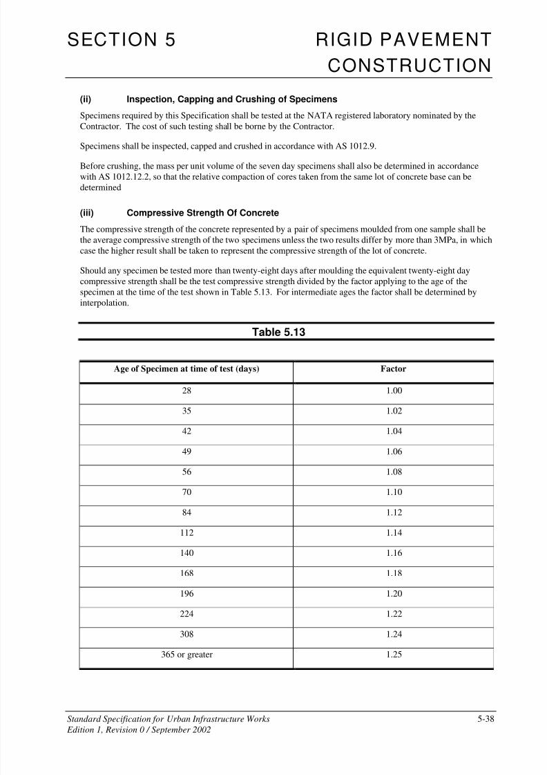
8/2/2019 6503712 Rigid Pavement SS05
http://slidepdf.com/reader/full/6503712-rigid-pavement-ss05 38/49
SECTION 5 RIGID PAVEMENT
CONSTRUCTION
Standard Specification for Urban Infrastructure Works 5-38
Edition 1, Revision 0 / September 2002
(ii) Inspection, Capping and Crushing of Specimens
Specimens required by this Specification shall be tested at the NATA registered laboratory nominated by the
Contractor. The cost of such testing shall be borne by the Contractor.
Specimens shall be inspected, capped and crushed in accordance with AS 1012.9.
Before crushing, the mass per unit volume of the seven day specimens shall also be determined in accordance
with AS 1012.12.2, so that the relative compaction of cores taken from the same lot of concrete base can be
determined
(iii) Compressive Strength Of Concrete
The compressive strength of the concrete represented by a pair of specimens moulded from one sample shall be
the average compressive strength of the two specimens unless the two results differ by more than 3MPa, in which
case the higher result shall be taken to represent the compressive strength of the lot of concrete.
Should any specimen be tested more than twenty-eight days after moulding the equivalent twenty-eight daycompressive strength shall be the test compressive strength divided by the factor applying to the age of the
specimen at the time of the test shown in Table 5.13. For intermediate ages the factor shall be determined by
interpolation.
Table 5.13
Age of Specimen at time of test (days) Factor
28 1.00
35 1.02
42 1.04
49 1.06
56 1.08
70 1.10
84 1.12
112 1.14
140 1.16
168 1.18
196 1.20
224 1.22
308 1.24
365 or greater 1.25
8/2/2019 6503712 Rigid Pavement SS05
http://slidepdf.com/reader/full/6503712-rigid-pavement-ss05 39/49
SECTION 5 RIGID PAVEMENT
CONSTRUCTION
Standard Specification for Urban Infrastructure Works 5-39
Edition 1, Revision 0 / September 2002
(iv) Conformance of Base Concrete
If the twenty eight (28) day compressive strength of test cylinders for any lot is less than 33MPa or greater than
45MPa, the lot represented by the test cylinders shall be removed and replaced in accordance with
Clause 5.14.6.
In case of nonconformance the Contractor may propose through disposition of a nonconformance report to core
the in situ concrete base for testing of the actual compressive strength to represent the particular lot. The
locations for testing shall be nominated by the Superintendent. Such locations may be determined by the use of a
nuclear density meter, or any alternative method. Testing shall be carried out at the request of the Contractor.
Base concrete failing to reach the required in situ compressive strength shall not be retested for at least 72 hours
after the determination of the value of the in situ compressive strength.
After testing for compressive strength of cores, where required, the Superintendent shall consider the test results
and shall at his absolute discretion determine the compressive strength of the concrete to be either:-
(a) The average of the twenty eight (28) day compressive strength of the pair of specimens moulded at
the time of placing; or
(b) The equivalent twenty eight (28) day compressive strength of the core.
A lot is defined as a continuous pour of up to 50 cubic metres of concrete base represented by a pair of test
specimens cast from a sample of the concrete used in its construction.
Compressive strength may also be determined from specimens cut from the work. Core specimens are to be
tested and conformance determined in accordance with Clause 5.14.3(iii).
(v) Conformance of Subbase Concrete
The minimum compressive strength at 7 days shall be 4MPa and at 28 days shall not be less than 5MPa for flyash
blended cement. The maximum compressive strength at 28 days shall be less than 15MPa, with the exceptionthat where the nominated mix demonstrates a 28 day shrinkage less than 400 microstrains, then the concrete
achieving a strength less than 20MPa shall be accepted.
If the compressive strength of test is nonconforming, the lot represented by the test cylinders shall be removed
and replaced in accordance with Clause 5.14.6.
In case of nonconformance the Contractor may propose through disposition of a nonconformance report to core
the in situ subbase for testing of the actual compressive strength to represent the particular lot. The locations for
testing shall be nominated by the Superintendent. Such locations may be determined by the use of a nuclear
density meter, or any alternative method. Testing shall be carried out at the request of the Contractor. Concrete
subbase failing to reach the required in situ compressive strength shall not be retested for at least 72 hours after
the determination of the value of the in situ compressive strength

8/2/2019 6503712 Rigid Pavement SS05
http://slidepdf.com/reader/full/6503712-rigid-pavement-ss05 40/49
SECTION 5 RIGID PAVEMENT
CONSTRUCTION
Standard Specification for Urban Infrastructure Works 5-40
Edition 1, Revision 0 / September 2002
5.14.2 Compaction and Tolerances
(i) Concrete Subbase
The finished surface of concrete pavement shall be uniform in appearance and shall comply with the tolerances
itemised in Table 5.14. Surface shape shall be such that water cannot accumulate at any point.
Table 5.14
Item Tolerance
Level +0mm, -20mm
Thickness + Unspecified, -10mm
Straightness 5mm maximum departure from 3m straightedge
both ways
Thickness measurements shall be determined by survey measurements or coring. If concrete paving thickness is
outside the specified limits, the work shall be removed and replaced in accordance with Clause
(ii) Dowels
The deformation from true shape of the ends of dowels shall not exceed 1 mm on the diameter of the dowel and
shall not extend more than 1mm from the end of the dowel.
Dowel bars shall be placed subject to the following tolerances:
• Two-thirds of the number of bars in the joint shall be within 2mm in 300mm.
• The remaining third, less one per 3m length of joint, shall be within 4mm in 300mm.
• No bar shall differ in alignment from an adjoining bar by more than 2mm in 300mm in either plane.
Before embedment in the slab, dowel bars shall be so fixed that, when subjected to a load of 13kg applied at
either end and in either the vertical or horizontal direction (upwards and downwards and both directions
horizontally) they do not deflect more than the following limits:
• Two-thirds of the number of bars shall not deflect more than 2mm in 300mm.
• The remainder of the bars shall not deflect more than 4mm i except that one bar in 12 may exceedthis deflection.
(iii) Concrete Base
The finished surface of concrete pavement shall be uniform in appearance and shall comply with the tolerances
itemised in Table 5.15. Surface shape shall be such that water cannot accumulate at any point.
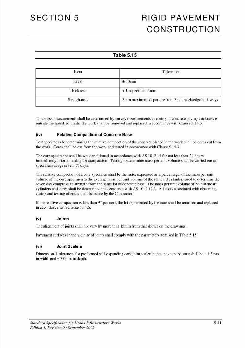
8/2/2019 6503712 Rigid Pavement SS05
http://slidepdf.com/reader/full/6503712-rigid-pavement-ss05 41/49
SECTION 5 RIGID PAVEMENT
CONSTRUCTION
Standard Specification for Urban Infrastructure Works 5-41
Edition 1, Revision 0 / September 2002
Table 5.15
Item Tolerance
Level ± 10mm
Thickness + Unspecified -5mm
Straightness 5mm maximum departure from 3m straightedge both ways
Thickness measurements shall be determined by survey measurements or coring. If concrete paving thickness is
outside the specified limits, the work shall be removed and replaced in accordance with Clause 5.14.6.
(iv) Relative Compaction of Concrete Base
Test specimens for determining the relative compaction of the concrete placed in the work shall be cores cut from
the work. Cores shall be cut from the work and tested in accordance with Clause 5.14.3
The core specimens shall be wet conditioned in accordance with AS 1012.14 for not less than 24 hours
immediately prior to testing for compaction. Testing to determine mass per unit volume shall be carried out on
specimens at age seven (7) days.
The relative compaction of a core specimen shall be the ratio, expressed as a percentage, of the mass per unit
volume of the core specimen to the average mass per unit volume of the standard cylinders used to determine the
seven day compressive strength from the same lot of concrete base. The mass per unit volume of both standardcylinders and cores shall be determined in accordance with AS 1012.12.2. All costs associated with obtaining,
curing and testing of cores shall be borne by the Contractor.
If the relative compaction is less than 97 per cent, the lot represented by the core shall be removed and replaced
in accordance with Clause 5.14.6.
(v) Joints
The alignment of joints shall not vary by more than 15mm from that shown on the drawings.
Pavement surfaces in the vicinity of joints shall comply with the parameters itemised in Table 5.15.
(vi) Joint Scalers
Dimensional tolerances for preformed self-expanding cork joint sealer in the unexpanded state shall be ± 1.5mm
in width and ± 3.0mm in depth.
8/2/2019 6503712 Rigid Pavement SS05
http://slidepdf.com/reader/full/6503712-rigid-pavement-ss05 42/49
SECTION 5 RIGID PAVEMENT
CONSTRUCTION
Standard Specification for Urban Infrastructure Works 5-42
Edition 1, Revision 0 / September 2002
5.14.3 Specimens cut from the Work
(i) Test Specimens
Cores cut from the work shall be cut from the full depth of the base concrete to the requirements of AS 1012.14,
with the following exceptions:
(a) The requirement that the concrete shall be at least twenty eight (28) days old before the core is
removed shall not apply. However concrete must be not less than three (3) days old in the summer
season and six (6) days old in the winter season, before removal.
(b) The nominal diameter of the cores shall not be less than 75mm.
The location of coring shall be chosen to exclude joints, steel reinforcement or tie bars from the core. The
locations are not intended to be random, but are intended to ensure that the whole of the concrete base conforms
to the minimum requirements of the Specification. Cores shall be marked for identification.
Cores shall be placed immediately either in a tank of lime saturated water or in an individual plastic bag and
sealed to prevent water loss. Cores stored in plastic bags shall be kept in the shade.
Cores shall not be subjected to temperatures in excess of either ambient temperature or 23oC whichever is the
higher and they shall not be subjected to temperature less than 10oC, until delivered to the testing laboratory.
(ii) Repair of Core Holes
The Contractor shall clean and restore all core holes taken in the base with non-shrink cementitious concrete
having a compressive strength of not less than that in the base and a maximum nominal aggregate size of 10mm.
The surface of the restored hole shall be similar to the surrounding surface in texture and colour.
The cost of restoring core holes shall be borne by the Contractor.
(iii) Conformance for Compressive Strength (Specimens cut from the work)
Core specimens cut from the work for compressive strength testing shall be wet-conditioned, prepared and tested
in accordance with AS 1012.14. Cores obtained for compaction shall not be re-used for compressive strength
testing.
The test strength shall be adjusted for age at test in accordance with Clause 5.14.1 (ii), Table 5.13 and for
length/diameter ratio in accordance with Table 5.16 by multiplying by the correction factor in Table 5.16
If the compressive strength of the core is nonconforming in accordance with Clause 5.14.1, the lot represented by
the compaction core shall be removed and replaced in accordance with Clause 5.14.6.

8/2/2019 6503712 Rigid Pavement SS05
http://slidepdf.com/reader/full/6503712-rigid-pavement-ss05 43/49
SECTION 5 RIGID PAVEMENT
CONSTRUCTION
Standard Specification for Urban Infrastructure Works 5-43
Edition 1, Revision 0 / September 2002
Table 5.16
Length/Diameter Ratio Correction Factor
2.00 1.00
1.75 0.98
1.50 0.96
1.25 0.93
1.00 0.89
5.14.4 Sampling and Testing
All sampling and testing of materials supplied and work carried out under this section of the Specification shall
be performed in accordance with the relevant Australian Standards or as otherwise specified.
Work under this Specification shall be subdivided into lots or discrete work areas. The Superintendent shall have
the right to reject a lot which is visually non-homogeneous and/or non-representative.
The specified testing shall be taken at the random test locations established in each lot in accordance with the
specified minimum testing frequency in Clause 5.14.3.
The test/s then taken shall be considered to represent the total volume of material placed within the lot.
5.14.5 Frequency of Testing
The frequency of testing shall be appropriate to verify conformity and shall not be less than that stated in
Table 5.17 Where no minimum frequency of inspection or testing is stated, the Contractor shall nominate
appropriate frequencies in their Inspection and Test Plan(s).
The Contractor shall include in the management review of the Quality System, a review of the appropriateness of
the frequency of testing nominated in the Inspection and Test Plan(s). Such review shall take into account the
frequency of nonconformance detected, including nonconformance remedied by simple reworking.

8/2/2019 6503712 Rigid Pavement SS05
http://slidepdf.com/reader/full/6503712-rigid-pavement-ss05 44/49
SECTION 5 RIGID PAVEMENT
CONSTRUCTION
Standard Specification for Urban Infrastructure Works 5-44
Edition 1, Revision 0 / September 2002
Table 5.17
Clause Characteristic Analysed Test Method Minimum Frequency Of Testing
Fine aggregate
5.03.2 (ii) Particle size distribution of
aggregate:
AS 1141.11 One per 400 tonnes
5.03.2 (ii) Bulk density AS 1141.4 In the trial mix
5.03.2 (ii) Soundness AS 1141.24 One per 4000 tonnes
Coarse aggregate
5.03.2 (iii) Particle size distribution; AS 1141.11 One per 400 tonnes
5.03.2 (iii) Bulk and particle density AS 1141.4,
AS 1141.6
In the trial mix
5.03.2 (iii) Water absorption AS 1141.6 One (1) within 12 months prior to
commencement of construction
5.03.2 (iii) Particle shape AS 1141.14 One (1) per 2000 tonnes
5.03.2 (iii) Wet strength AS1141.22 One (1) per 2000 tonnes
5.03.2 (iii) Wet/dry strength variation AS1141.22 One (1) per 2000 tonnes
5.03.2 (iii) Fractured faces AS1141.18 One (1) per 1000 tonnes
Concrete
5.03.2 (i) Soluble Sulphate Salt AS 2758.1 One (1) per 30,000 m3
of concrete
5.03.4, 5.05.1,
5.08.4
Concrete slump AS 1012.3
Method 1
One (1) for each lot up to 50m3 of
concrete placed at one time
5.03.4, 5.05.1 Air content of concrete AS 1012.4
Method 2
In the trial mix and one (1) per
10,000 m3 of concrete
5.03.4, 5.05.1 Drying shrinkage AS 1012.13,
with compaction
by external
vibration
In the trial mix and one (1) per
10,000 m3 of concrete
5.03.4, 5.05.1 Combined aggregate particle
grading
AS 1141.11 In the trial mix and one (1) per 800
tonne of course aggregate
5.03.4 Flexural strength AS 1012.11 In the trial mix and one (1) per
500 m3
of concrete

8/2/2019 6503712 Rigid Pavement SS05
http://slidepdf.com/reader/full/6503712-rigid-pavement-ss05 45/49
SECTION 5 RIGID PAVEMENT
CONSTRUCTION
Standard Specification for Urban Infrastructure Works 5-45
Edition 1, Revision 0 / September 2002
Clause Characteristic Analysed Test Method Minimum Frequency Of Testing
5.03.4, 5.05.1,
5.14.1
Compressive Strength at 28
days – Concrete Cylinders
AS 1012.9 One (1) pair of specimens for each lot
up to 50 m3 of concrete placed at one
time
5.03.4, 5.05.1,
5.14.1
Compressive Strength
Compressive Strength at 7
days – Concrete Cylinders
AS 1012.9 One (1) pair of specimens for each lot
up to 50 m3
of concrete placed at one
time
5.14.2 Relative Compaction of
Concrete – Cores cut from the
work
AS 1012.12
Method 2
Two (2) cores from each lot until
three (3) consecutive conforming lots,
then One (1) from three (3) lots until
three (3) consecutive conforming,
then one (1) from five (5) lots.
5.14.2 Level and thickness of
concrete
Survey /
AS 2876
Survey levels in the same location
prior to and after placement of sub-base and base. Every 20 m2.
5.14.2 Surface profile Deviation from
Straight Edge
As per Clause 5.5
5.07 Pull-out test on tiebars and
dowels
Measure Three (3) prior to construction
5.11.2 Application rate of curing
compound
Measure One (1) per 2000 m2
of base
5.09.3 (iii);
5.09.4 (iii)
Average depth of longitudinal
surface texture
Measure One (1) per 2000 m2 of base
5.10 Straightness of Joint Deviation from
Straight Edge
As per Clause 5.5
5.14.6 Nonconforming Work
(i) Removal of Nonconforming Concrete
Where directed by the Superintendent, rejected base shall be removed and replaced in accordance with this
Clause. Rejected base, which extends more than 25m longitudinally, shall be replaced by mechanical means
unless the slabs are odd-shaped or mismatched. Replacement shall be in full slab widths between longitudinal
joints and/or external edges.
At least seven (7) days before the commencement of base removal, the Contractor shall submit, for the approval
of the Superintendent, details of the proposed methods of carrying out the work which shall be such as to prevent
damage to the adjoining base and the underlying subbase.
The cost of all work and materials under this Clause shall be borne by the Contractor.
8/2/2019 6503712 Rigid Pavement SS05
http://slidepdf.com/reader/full/6503712-rigid-pavement-ss05 46/49
SECTION 5 RIGID PAVEMENT
CONSTRUCTION
Standard Specification for Urban Infrastructure Works 5-46
Edition 1, Revision 0 / September 2002
(ii) Removal and Disposal of Concrete Base
At each end of the section of base to be removed, a transverse sawcut shall be made for the full depth of the base
layer. Such transverse sawcuts shall be normal to the control line and not closer than 1.5m to an existing
contraction joint in the base. No oversawing into the adjoining base or underlying subbase shall be permitted.
Longitudinal sawcuts shall be made along existing longitudinal joints to define the edges of the base section to be
removed. Such longitudinal sawcuts shall not extend more than 250mm past the transverse sawcut at each end of
the section to be removed and shall not extend into the underlying subbase.
No oversawing shall be permitted on any additional internal sawcuts the Contractor may make to aid the removal
of the base.
The Contractor shall dispose of the removed base slabs at locations acceptable to the Superintendent.
Any slab, adjoining the removed slabs, damaged by the Contractor's operations shall also be removed and
replaced in accordance with this Clause.
Hold Point 5.7
Process Held: Removal and disposal of nonconforming concrete.
Submission Details: At least five (5) working days prior to commencement of work the Contractor
shall submit details of the equipment and methods proposed for removal and
disposal of concrete paving.
Release of Hold Point: The Superintendent will review the submitted details, prior to authorising the
release of the Hold Point.
(iii) Replacement of Concrete Base
Before construction of the replacement base, the subbase shall be prepared and debonded in accordance with this
Specification.
All work involved in the replacement of base shall comply with the Specification, including the following
additional requirements:-
(a) The joint faces on the adjoining slab at the transverse sawcuts shall be deeply scabbled below the
top 25mm which shall be left smooth. Tie bars shall be provided to form a transverse construction
joint in accordance with this specification.
(b) Transverse contraction joints shall be continuous across the full width of the base containing the
replaced section. The length of the joint across the full width of the base shall be sealed with the
same sealant as in adjacent work and in accordance with this specification.
(c) The lower two-thirds of the depth of the longitudinal joint faces shall be deeply scabbled and any
concrete considered to be unsound by the Superintendent shall be removed. A crack inducer ribbon
shall be attached to the surface of any formed longitudinal joint in the replacement base and tie bars
provided to form a longitudinal tied joint in accordance with this specification.
(d) Tie bars placed into hardened concrete shall be set by the use of a hydrophilic epoxy resin. The
setting system used shall develop an anchorage strength at least 85 per cent of the yield strength of
the bar.
8/2/2019 6503712 Rigid Pavement SS05
http://slidepdf.com/reader/full/6503712-rigid-pavement-ss05 47/49
SECTION 5 RIGID PAVEMENT
CONSTRUCTION
Standard Specification for Urban Infrastructure Works 5-47
Edition 1, Revision 0 / September 2002
(e) No traffic will be permitted on the pavement until curing is complete. Traffic shall be excluded from
the finished concrete until it is at least 14 days old, except that paving equipment other than concrete
trucks will be permitted after curing is completed, provided that adequate means are furnished to
prevent damage to slab edges, and that all spilled materials are removed immediately.
5.15 MEASUREMENT AND PAYMENT
Payment shall be made for all activities associated with completing the work detailed in this Specification in
accordance with Pay Items 505P1-P3, 507P1-P2, 507P1-P2, 508P1, 509P1-P2, 510P1-P4 and 511P1 inclusive.
Unless specified otherwise a lump sum price for any of these items will not be accepted.
If any item for which a quantity of work is listed in the Contract has not been priced by the Contractor, it shall be
understood that due allowance has been made in the prices of other items for the cost of the activity which has
not been priced.
The Contractor shall allow in the pay items generally for the costs associated with all testing required to proveconformance of the works as specified.
Where the compressive strength of test cylinders for any lot is less than specified, the lot represented by the test
cylinders shall be removed, in which case no payment shall be made.
Where the relative compaction of the base concrete is less than specified, the lot represented by the core shall be
removed, in which case no payment shall be made.
Where the concrete thickness is more than the allowable tolerance below the specified thickness, the concrete
shall be removed, in which case no payment shall be made.
Pay Item 505P1 Supply and Place Concrete in Subbase
The unit of measurement shall be the cubic metre in place.
The width and length shall be as specified on the Drawings or as directed by the Superintendent.
The depths shall be the depths specified or as directed by the Superintendent across each section.
No account shall be taken of the allowable tolerances.
The cost of providing transverse construction joints and longitudinal construction joints shall be included in the
schedule rate for this pay item.
Pay Item 505P2 Finish and Cure Subbase
The unit of measurement shall be the square metre of subbase.
The width and length shall be taken as specified on the drawings or as directed by the Superintendent.
No account shall be taken of the allowance tolerances.
The sides of slabs shall not be included in the measurement of surface area.
Pay Item 505P3 Subgrade Beams
The unit of measurement shall be the cubic metre.
The volume shall be determined by multiplying the width, length and depth as specified on the drawings or asdirected by the Superintendent.

8/2/2019 6503712 Rigid Pavement SS05
http://slidepdf.com/reader/full/6503712-rigid-pavement-ss05 48/49
SECTION 5 RIGID PAVEMENT
CONSTRUCTION
Standard Specification for Urban Infrastructure Works 5-48
Edition 1, Revision 0 / September 2002
The rate shall include all activities and materials to complete the subgrade beams as shown on the drawings.
Pay Item 507P1 Supply and Place Wire Reinforcing Fabric
The unit of measurement shall be the square metre of wire reinforcing fabric placed.
The width and length shall be as specified on the drawings, including odd-shaped and mismatched slabs, or as
directed by the Superintendent. No account shall be taken of the allowable tolerances nor of any laps.
Unless specified otherwise, all wire reinforcing fabric shall be paid under this pay item.
Pay Item 507P2 Supply and Install Steel Bar Reinforcement
The unit of measurement shall be the tonne of steel reinforcement.
The mass shall be determined from the unit masses given in Table 4 of AS 1302 and the actual length of bar
measured in place. No account shall be taken of laps and splices.
Unless otherwise indicated, all steel bar reinforcement shall be paid for at the as part of this pay item.
The pay item excludes dowels and tie bars.
Pay Item 508P1 Supply and Place Concrete in Base
The unit of measurement shall be the cubic metre in place
The width and length shall be as specified on the drawings, including odd-shaped and mismatched slabs, or as
directed by the Superintendent. The depth shall be the depth specified or as directed by the Superintendent
across each section.
No account shall be taken of the allowable tolerances.
Pay Item 509P1 Finish, Cure and Texture Base
The unit of measurement shall be the square metre of surface of the base.
The width and length shall be as specified on the drawings, including odd-shaped and mismatched slabs, or as
directed by the Superintendent.
No account shall be taken of the allowable tolerances.
The sides of slabs shall not be included in the measurement of surface area.
Pay Item 509P2 Slab Anchors
The unit of measurement shall be the cubic metre of concrete.
The volume shall be taken from the drawings with appropriate adjustments being made for any authorised
variation. The depth shall be measured from the top of the subbase.
The pay item includes all work, materials and equipment required for the construction of slab anchors including
excavation, disposal of material, supply and placing of reinforcement and the subsoil drain.
Pay Item 510P1 Transverse Contraction Joints
The unit of measurement shall be the linear metre.
The distance shall be measured along the line of the joint.

8/2/2019 6503712 Rigid Pavement SS05
http://slidepdf.com/reader/full/6503712-rigid-pavement-ss05 49/49
SECTION 5 RIGID PAVEMENT
CONSTRUCTION
Pay Item 510P2 Transverse Expansion and Isolation Joints
The unit of measurement shall be the linear metre.
The distance shall be measured along the line of the joint.
Pay Item 510P3 Longitudinal Tied Joints
The unit of measurement shall be the linear metre.
The distance shall be measured along the line of the joint.
The pay item includes provision of tie bars.
Pay Item 510P4 Longitudinal Isolation Joints
The unit of measurement shall be the linear metre.
The length shall be measured along the line of the joint.
The pay item includes the provision of dowels where specified or shown on the Drawings.
Pay Item 511P1 Bond Breaker
The unit of measurement shall be the square metre.
The area shall be determined by multiplying the actual length with design width as shown on the Drawings. No
account shall be taken of tolerances.
5.16 SCHEDULE OF HOLD POINTS
Hold Points Clause Description
5.1 5.03.4 Placement of concrete paving - Submit details of the concrete mix
design
5.2 5.03.6 Sealing of Joints - Submit a certificate of compliance from a NATA
registered laboratory
5.3 5.07 Reinforcement fixing - Inspection
5.4 5.08.1 Proposed methods of handling, storing and batching materials forconcrete – Submit details
5.5 5.09.1 Equipment and methods proposed for placing and finishing the
concrete – Submit details
5.6 5.11.2 Curing Membrane – Submit details
5.7 5.14.6 Removal and disposal of nonconforming concrete
Related Documents