surface 1 or over the equivalent end aperture planes, 2 essentially contain the dominant term Uy(K-cos6)\ kL (K-cosQ) where K — /. 0 [/. g , k = — and ?. g is the rod wavelength. At frequencies outside the stop- ts M Fig. 1A Composite rod structure - 20 Fig. IB Radiation patterns at gigahertz frequencies band, it might be expected that the difference between the uniform-rod and composite-rod patterns could be explained by the diff ere nt dispersion relationship s of the two structures. However, since the mean relative permittivity of the composite ro d is l ess than that of the uniform rod, this indicates that K will be smaller for the composite rod. This was confirmed by measurements which gave a value K = 1-22 for the composite rod compared to K = 1- 33 for the uniform rod at 9-4 GHz. The radiation-pattern equations indicate that the beamwidth of the composite should be greater than the uniform-rod beamwidth. This is seen to be the case at frequencies below the stopband, but the opposite is true for frequencies above the stopband. The equation suggests that the angular posi- tions of the sidelobes should lie closer to the main beam for the uniform rod than for the composite rod, and this was found to be the case. The equation also indicates that the first sidelobe levels should be approximately 4-6 dB great er for the uniform rod, and this is found to be the case above the stopband, but appears to be somewhat less below the stop- band. Since the increased gain property of a composite structure is not a surface-wave-propagation effect, an explana- tion in terms of the modifying influence of the rod structures on the direct radiation from the feed waveguide 3 - 4 appears to be more likely. J. R. BLAKEY 5t h February 1973 Microwave Physics Group epartment of Physics University of Surrey Guildford, Surrey, England References 1 KEILY, D. c : Progress in dielectrics , (Heyw ood, 1961) , 3, pp. 1—45 2 JAMES, j . R.: Theoretical investigation of cylindrical dielectric rod antennas , Proc. IEE, 196/, 114, (3), pp. 309-319 3 BLAKEY, j . R.: Calculation of dielectric-aerial-radiation patterns , Electron. Lett., 1968,4, pp. 46-47 4 AND ERSE N, j . B.: Metallic and dielectric aerials . Polyteknisk Forlag, Lyngby, 1971 uniform rod composite rod 8 -5 9-0 9 5 frequencyjGHz 1 0 0 Fig. 2 Beamwidth and sidelobe levels against frequency for both rods uniform rod / composite rod ELECTRONICS LETTERS 22nd March 1973 Vol.9 No. PRECISION DIFFERENTIAL VOLTAGE- CURRENT CONVERTOR Indexing terms: Magnitude convertors, Integrated circuits, Differential amplifiers new differential voltage-current conv enor is proposed, which achieves high linearity and is substantially temperature independent. The effects of transistor mismatches and of limited current gain are analysed. Experim ental results are given which show a considerable improvement over previous circuits. In m any integrated circuits, for example multipliers, 1 t he first stage is a differential voltage-current convertor, consisting o f a simple differen tial pair with a feedback resistor R E between the emitters. This circuit gives satisfactory performances only if the resistance R E is large compared with the dynamic resistance of the transistors; otherwise the overall transconductance of the circuit is strongly temperature dependent and essentially nonlinear. On the other hand, a high value of R E increases the noise, and this again limits the dynamic range. The circuit proposed (Fig. l a) performs a precision low-distortion voltage-current conversion, even with low values of R E , thus improving the dynamic range. Consider the sum of the voltages around the loop com- prising the signal generator, the base-emitter voltages of T r ls Tr 4 , Tr 2 and Tr 3 and the feedback resistor R E : v ~V BEl - V BE t - iR E + V BE + V BE 3 = 0 Eqn. 1 can also be written as follows: (1) v-iR E + , £2 ] n / £ 3 _ |n / c i _ S2 S3 SI IS where I s are the reverse saturation currents. 14 7

Welcome message from author
This document is posted to help you gain knowledge. Please leave a comment to let me know what you think about it! Share it to your friends and learn new things together.
Transcript
8/13/2019 65 Caprio ElecLett 1973
http://slidepdf.com/reader/full/65-caprio-eleclett-1973 1/2
surface1 or over the equivalent end aperture planes, 2
essentially contain the dominant term
Uy(K-cos6)\
kL(K-cosQ)
where K — /.0[/.g, k = —
and ?.g is the rod wavelength. At frequencies outside the stop-
tsM
Fig. 1A Composite rod structure
-2 0
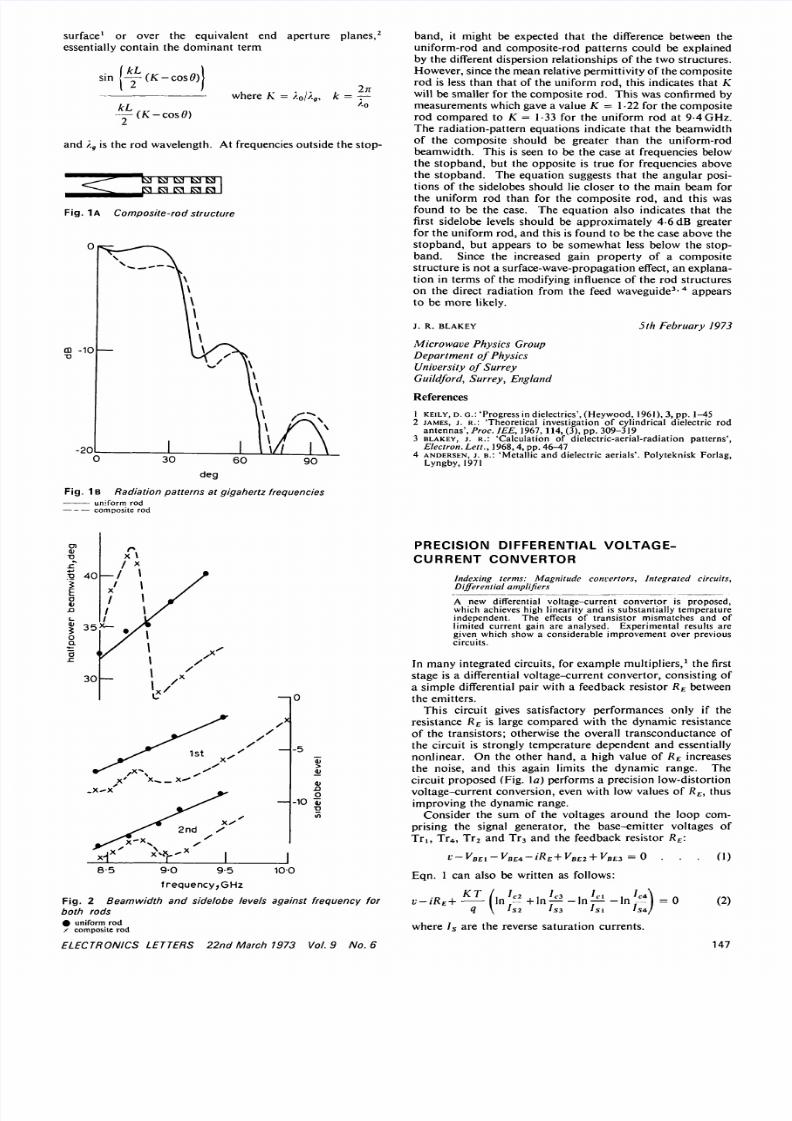
Fig. IB Radiation patterns at gigahertz frequencies
band, it might be expected that the difference between theuniform-rod and composite-rod patterns could be explainedby the different dispersion relationships of the two structures.However, since the mean relative permittivity of the compositerod is less than that of the uniform rod, this indicates that Kwill be smaller for the composite rod. This was confirmed bymeasurements which gave a value K = 1-22 for the compositerod compared to K = 1-33 for the uniform rod at 9-4 GHz.The radiation-pattern equations indicate that the beamwidthof the composite should be greater than the uniform-rodbeamwidth. This is seen to be the case at frequencies belowthe stopband, but the opposite is true for frequencies above
the stopband. The equation suggests that the angular posi-tions of the sidelobes should lie closer to the main beam forthe uniform rod than for the composite rod, and this wasfound to be the case. The equation also indicates that thefirst sidelobe levels should be approximately 4-6 dB greaterfor the uniform rod, and this is found to be the case above thestopband, but appears to be somewhat less below the stop-band. Since the increased gain property of a compositestructure is not a surface-wave-propagation effect, an explana-tion in terms of the modifying influence of the rod structureson the direct radiation from the feed waveguide 3-4 appearsto be more likely.
J. R. BLAKEY 5th February 1973
Microwave Physics Group epartment of PhysicsUniversity of SurreyGuildford, Surrey, England
References
1 KEILY, D. c : Progress in dielectrics , (Heyw ood, 1961), 3, pp. 1—452 JAMES, j . R. : Theoretical investigation of cylindrical dielectric rod
antennas , Proc. IEE, 196/, 114, (3), pp. 309-3193 BLAKEY, j . R. : Calculation of dielectric-aerial-radiation patterns ,
Electron. Lett., 1968,4, pp. 46-474 ANDERSEN, j . B.: Metallic and dielectric aerials . Polyteknisk Forlag ,
Lyngby, 1971
uniform rodcomposite rod
8-5 9-0 9 5
frequencyjGHz
1 0 0
Fig. 2 Beamwidth and sidelobe levels against frequency forboth rods uniform rod/ composite rod
ELECTRONICS LETTERS 22nd March 1973 Vol.9 No.
PRECISION DIFFERENTIAL VOLTAGE-
CURRENT CONVERTOR
Indexing terms: Magnitude convertors, Integrated circuits,Differential amplifiers
A new differential voltage-current conv enor is proposed,which achieves high linearity and is substantially temperatureindependent. The effects of transistor mismatches and oflimited current gain are analysed. Experim ental results aregiven which show a considerable improvement over previouscircuits.
In m any integrated circuits, for example multipliers, 1 the first
stage is a differential voltage-current convertor, consisting of
a simple differential pair with a feedback resistor RE betweenthe emitters.This circuit gives satisfactory performances only if the
resistance RE is large compared with the dynamic resistanceof the transistors; otherwise the overall transconductance ofthe circuit is strongly temperature dependent and essentiallynonlinear. On the other hand, a high value of RE increasesthe noise, and this again limits the dynamic range. Thecircuit proposed (Fig. l a) performs a precision low-distortionvoltage-current conversion, even with low values of RE, thusimproving the dynamic range.
Consider the sum of the voltages around the loop com-prising the signal generator, the base-emitter voltages ofTr l s Tr 4, Tr2 and Tr3 and the feedback resistor RE:
v ~VBEl- VBEt - iRE+ VBE + VBE 3 = 0
Eqn. 1 can also be written as follows:
(1)
v-iRE +, £2 ] n/ £ 3 _ | n / c i _
S2 S3 SI IS
where Is are the reverse saturation currents.
14 7
8/13/2019 65 Caprio ElecLett 1973
http://slidepdf.com/reader/full/65-caprio-eleclett-1973 2/2
If the transistors are perfectly matched, and the current
gains are high enough to neglect the base currents, eqn. 2
collapses to the simple form
R, 3)
which describes the behaviour of a distortionless temperature-
independent voltage-current convertor with a transconduc-
tance uniquely set by the resistor RE.
Note that the only hypotheses used in deriving eqn. 3
' (W)C 4
Fig. 1a Voltage-current convertor
Fig. \b Alternative configuration
concern the matching and current gains of the transistors;
so the result holds for any value of the input voltage v and of
the feedback resistor RE, until the currents are sufficient to
keep the current gain high and validate the expression for the
base-emitter voltage drop adopted in eqn. 2. The maximum
input voltage is limited by saturation of Tr2 and Tr 4, biased
at VCB = 0; this limitation can be overcome by adding level-
shifting stages.
An alternative application of the proposed circuit is shown
in Fig. \b. This configuration has the same behaviour as the
previous one, but with a better frequency response, owing to
the common-base operation of the transistors, and without
voltage-swing limitation. The input impedance seen looking
into the emitters of Tr2 and Tr 4 is, in theory, zero, indepen-
dent of the bias current l0.
The operation of the circuit can be also explained as a
unity-gain positive-feedback which increases to infinite
gain in the negative-feedback loop set by resistor RE, thus
reducing to zero any error in the voltage-current conversion.
At high frequencies, parasitic inductances can lead to a
small negative resistance between the emitters of Tr 2 and Tr 4;
so , to overcome stability problems, RE must not be too low.In the configuration of Fig. \a, the internal resistance of
the voltage generator can also lead to instability; a small
capacitor between the bases of Trx and Tr 3 is sufficient to
avoid this possibility. Transistor mismatch does not alter
the performances of the circuits. In this case, eqn. 2 becomes
v + (4)
which shows that an input offset voltage is present, but the
transconductance and linearity are not affected.
Let us now consider the effect of limited current gain, with
the simplified hypothesis of current gain being equal for all
transistors and constant for any bias current.
We must consider two effects. First the variable component
of the output current is reduced with respect to the current iby a constant factor dependent on the current gain; straight-
forward analysis gives, in fact,
(5)
Secondly, the variable current / is no longer linearly depen-
dent on the input voltage. With X = 2i/I0, the collector
currents can be written as
(6)
+ ln =
and eqn. 2 becomes
v-iRE+q
If the current is small, x is small with respect to unity and we
can consider only the first two terms of the power expansion of
the logarithm; with simple mathematics, we obtain
f l + X 2a-l)
I 1-X 2a-1)
qh 3 qlo V(8)
The overall effect is a reduction of the circuit transcon-
ductance, which becomes slightly temperature-dependent, and
the introduction of 3rd-order harmonic distortion; current-
gain mismatches will introduce additional 2nd-order dis-
tortion.
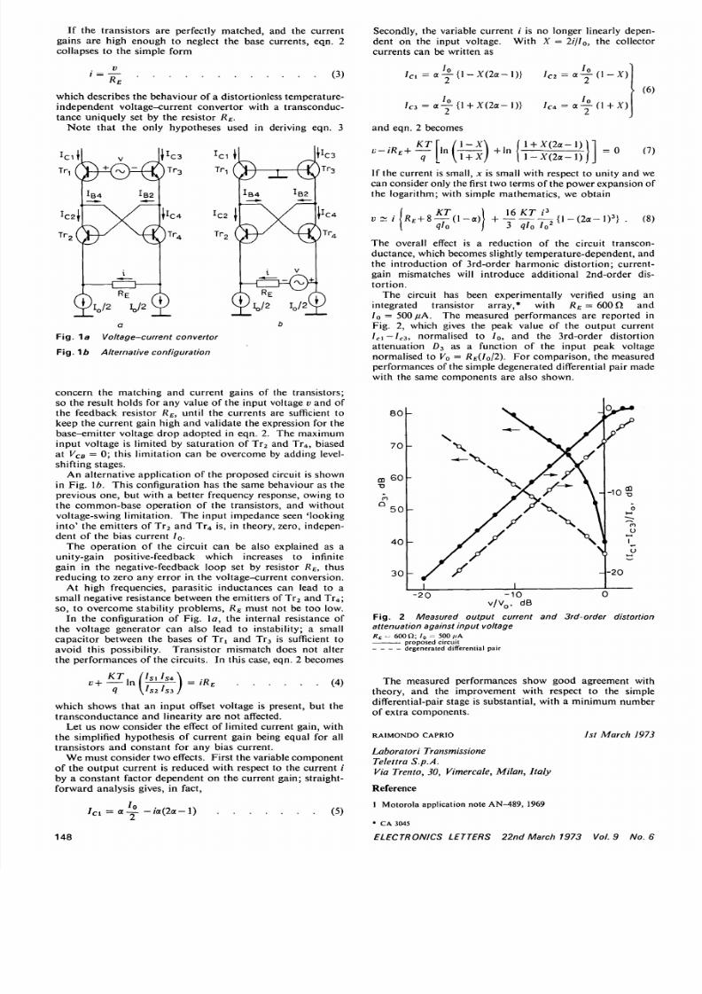
The circuit has been experimentally verified using an
integrated transistor array,* with 7?£ = 600Q and/ 0 = 500 fiA. The measured performances are reported in
Fig. 2, which gives the peak value of the output current
Ic\—IC3, normalised to Io, and the 3rd-order distortion
attenuation D3 as a function of the input peak voltage
normalised to Vo = RE(I0/2). For comparison, the measured
performances of the simple degenerated differential pair made
with the same components are also shown.
80
70
60
nQ
50
40
30
—XX
1 1
-io S
o
| J- 2 0
- 2 0 -1 0v /V o . dB
148
Fig. 2 Measured output current and 3rd-order distortionattenuation against input voltageRE ^ 600 Q ; r = 5 fiA
•—- proposed circuitdegenerated differential pair
The measured performances show good agreement with
theory, and the improvement with respect to the simple
differential-pair stage is substantial, with a minimum number
of extra components.
RAIMONDO CAPRIO Jst March 1973
Laboratori Transmissione
Telettra S.p.A.Via Trento, 30, Vimercale, Milan, Italy
Reference
1 Motorola application note AN-489, 1969
CA3O45
ELECTRONICS LETTERS 22nd March 1973 Vol.9 No.
Related Documents


![AAS 65 [1973] - ocr](https://static.cupdf.com/doc/110x72/55cf9c3d550346d033a9259d/aas-65-1973-ocr.jpg)