6.3.4 NUMERICAL EXAMPLES Example 6.1 Given the following stress function cos r P Determine the stress components r r and , Solution: The stress components, by definition of , are given as follows 2 2 2 1 1 r r r r (i) 2 2 r (ii) r r r r 2 2 1 1 (iii) The various derivatives are as follows: cos P r 0 2 2 r cos sin r P sin 2 cos 2 2 r P cos sin 2 P r Substituting the above values in equations (i), (ii) and (iii), we get sin 2 cos 1 cos 1 2 r P r P r r sin 2 1 cos 1 cos 1 P r P r P r sin 2 P r r 0 2 2 r cos sin 1 cos sin 1 2 P r r P r r 0 r Therefore, the stress components are

Welcome message from author
This document is posted to help you gain knowledge. Please leave a comment to let me know what you think about it! Share it to your friends and learn new things together.
Transcript

6.3.4 NUMERICAL EXAMPLES
Example 6.1
Given the following stress function
cosrP
Determine the stress components rr and,
Solution: The stress components, by definition of , are given as follows
2
2
2
11
rrrr
(i)
2
2
r
(ii)
rrrr
2
2
11 (iii)
The various derivatives are as follows:
cos
P
r
02
2
r
cossin
r
P
sin2cos
2
2
r
P
cossin
2
P
r
Substituting the above values in equations (i), (ii) and (iii), we get
sin2cos1
cos1
2
r
P
r
P
rr
sin21
cos1
cos1 P
r
P
r
P
r
sin2 P
rr
02
2
r
cossin1
cossin12
P
rr
P
rr
0 r
Therefore, the stress components are

sin2 P
rr
0
0 r
Example 6.2
A thick cylinder of inner radius 10cm and outer radius 15cm is subjected to an internal pressure of
12MPa. Determine the radial and hoop stresses in the cylinder at the inner and outer surfaces.
Solution: The radial stress in the cylinder is given by
r = 2
22
2222
22
r
ba
ab
pp
ab
bpap oioi
The hoop stress in the cylinder is given by
= 2
22
2222
22
r
ba
ab
pp
ab
bpap oioi
As the cylinder is subjected to internal pressure only, the above expressions
reduce to
r = 2
22
2222
2
r
ba
ab
p
ab
ap ii
and = 2
22
2222
2
r
ba
ab
p
ab
ap ii
Stresses at inner face of the cylinder (i.e., at r = 10 cm):
Radial stress = r =
222
22
22
2
)1.0()15.0(
12
)1.0(
)1.0()15.0(
)1.0()15.0(
)1.0(12
= 9.6 – 21.6
or r = -12 MPa
Hoop stress = =
2
22
2222
2
)1.0(
)1.0()15.0(
)1.0()15.0(
12
)1.0()15.0(
)1.0(12
= 9.6 + 21.6
or = 31.2 MPa
Stresses at outerface of the cylinder (i.e., at r = 15 cm):
Radial stress = r =
2
22
2222
2
)15.0(
)15.0()1.0(
)1.0()15.0(
12
)1.0()15.0(
)1.0(12
r = 0

Hoop stress = =
222
22
22
2
)1.0()15.0(
12
)15.0(
)15.0()1.0(
)1.0()15.0(
)1.0(12
= 9.6 + 9.6
or = 19.2 MPa
Example 6.3
A steel tube, which has an outside diameter of 10cm and inside diameter of 5cm, is subjected to an
internal pressure of 14 MPa and an external pressure of 5.5 MPa. Calculate the maximum hoop
stress in the tube.
Solution: The maximum hoop stress occurs at r = a.
Therefore, Maximum hoop stress = ()max =
2
22
22
0
22
2
0
2
a
ba
ab
pp
ab
bpap ii
= 2
22
0
22
2
0
2
bab
pp
ab
bpap ii
= 22
2
0
22
0
2
ab
bpbpbpap ii
()max = 22
2
0
22 2)(
ab
bpbapi
Therefore, ()max = 2
)05.0(2
)1.0(
2)1.0(5.52]
2)1.0(
2)05.0[(14
Or ()max = 8.67 MPa
Example 6.4
A steel cylinder which has an inside diameter of 1m is subjected to an internal pressure of 8 MPa.
Calculate the wall thickness if the maximum shearing stress is not to exceed
35 MPa.
Solution: The critical point lies on the inner surface of the cylinder, i.e., at r = a.
We have, Radial stress = r = 2
22
22
0
22
2
0
2
r
ba
ab
pp
ab
bpap ii
At r = a and 0p = 0,
r = 2
22
2222
2 00
a
ba
ab
p
ab
ap ii
= 22
22
ab
bpap ii

= )(
)(22
22
ab
abpi
Therefore, r = ip
Similarly,
Hoop stress = = 2
22
22
0
22
2
0
2
r
ba
ab
pp
ab
bpap ii
At r = a and 0p = 0,
= 2
22
2222
2 00
a
ba
ab
p
ab
ap ii
= )(
)(22
22
ab
bapi
Here the maximum and minimum stresses are
3 = ip and 1 =
But the maximum shear stress = max = 312
1
i.e. max =
i
i pab
bap22
22
2
1
=
22
2222
2
1
ab
apbpbpap iiii
35 = )( 22
2
ab
bpi
i.e., 35 = )(
822
2
ab
b
35b2-35a2
= 8b2
35b2-8b2
= 35a2
35b2-8b2
=35(0.5)2
Therefore, b = 0.5693
If t is the thickness of the cylinder, then
b = 0.5+ t = 0.5693
t = 0.0693 m or 69.3 mm.
Example 6.5
The circular link shown in Figure 6.14 has a circular cross-section 3cm in diameter. The inside
diameter of the ring is 4cm. The load P is 1000 kg. Calculate the stress at A and B. Compare the

values with those found by the straight beam formula. Assume that the material is not stressed
above its elastic strength.
Solution:
Cross-sectional area = A= 4
(3)
2 = 7.06 cm
2.
For circular cross-section m is given by
m = -1+2
2
c
R –2
c
R1
2
c
R
Here R = 2+1.5 = 3.5 cm
c = 1.5 cm. (Refer Table 6.1)
Therefore, Figure 6.14 Loaded circular link
m = 15.1
5.3
5.1
5.32
5.1
5.321
22
m = 0.050
At section AB, the load is resolved into a load P and a bending couple whose moment is positive. The
stress at A and B is considered to be the sum of the stress due to axial load P, and the stress due to the
bending moment M.
Therefore, Stress at point A is
A= A =
)(1
A
A
yRm
y
AR
M
A
P
= -
)5.15.3(050.0
)5.1(1
5.306.7
)10005.3(
06.7
1000
or A = -2124.65 kg/cm2 (compressive).
The stress at point B is given by
B = B = +
B
B
yRm
y
AR
M
A
P
(1
=
)5.15.3(050.0
5.11
5.306.7
3500
06.7
1000
B = 849.85 kg/cm2 (Tensile)
Comparison by Straight Beam Formula
The moment of inertia of the ring cross-section about the centroidal axis is
I = 444
976.364
)3(
64cm
d
If the link is considered to be a straight beam, the corresponding values are
.. AB
P
R

A = I
My
A
P
= - 976.3
)5.1)(3500(
06.7
1000
A = -1462.06 kg/cm2 (compressive)
& B = 976.3
5.13500
06.7
1000
B = 1178.8 kg/cm2 (tensile)
Figure 6.15 Stresses along the cross-section
Example 6.6
An open ring having T-Section as shown in the Figure 6.16 is subjected to a compressive load of
10,000 kg. Compute the stresses at A and B by curved beam formula.
1178.8
849.85
Straight beam
Curved beam
1462.06
2124.65
.
.
Centroid axis
Neutral axis
A
B
d
10cm
.. AB
18cm
P=10,000Kg
10.34cm
R
14cm
2cm
2cm
.
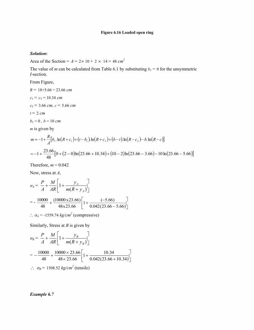
Figure 6.16 Loaded open ring
Solution:
Area of the Section = A = 2 10 + 2 14 = 48 cm2
The value of m can be calculated from Table 6.1 by substituting b1 = 0 for the unsymmetric
I-section.
From Figure,
R = 18+5.66 = 23.66 cm
c1 = c3 = 10.34 cm
c2 = 3.66 cm, c = 5.66 cm
t = 2 cm
b1 = 0 , b = 10 cm
m is given by
cRbcRtbcRbtcRbA
Rm ln.ln.ln.ln.1 23111
66.566.23ln1066.366.23ln21034.1066.23ln02048
66.231
Therefore, m = 0.042
Now, stress at A,
A =
)(1
A
A
yRm
y
AR
M
A
P
= -
)66.566.23(042.0
)66.5(1
66.23x48
)66.23x10000(
48
10000
A = -1559.74 kg/cm2 (compressive)
Similarly, Stress at B is given by
B =
)(1
B
B
yRm
y
AR
M
A
P
=
)34.1066.23(042.0
34.101
66.2348
66.2310000
48
10000
B = 1508.52 kg/cm2 (tensile)
Example 6.7
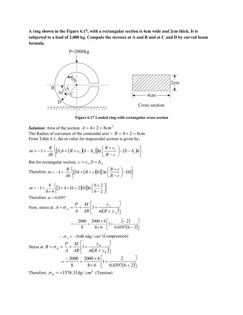
A ring shown in the Figure 6.17, with a rectangular section is 4cm wide and 2cm thick. It is
subjected to a load of 2,000 kg. Compute the stresses at A and B and at C and D by curved beam
formula.
Figure 6.17 Loaded ring with rectangular cross-section
Solution: Area of the section 2824 cmA
The Radius of curvature of the centroidal axis = .624 cmR
From Table 6.1, the m value for trapezoidal section is given by,
hbb
cR
cRbbcRhb
Ah
Rm 1
1111 ln1
But for rectangular section, ,, 11 bbcc
Therefore
0ln01
cR
cRcRbh
Ah
Rm
26
26ln02642
48
61m
Therefore 0397.0m
Now, stress at
A
AA
yRm
y
AR
M
A
PA 1
260397.0
21
68
62000
8
2000
2/6.3148 cmkgA (Compression)
Stress at
B
BB
yRm
y
AR
M
A
PB 1
260397.0
21
68
62000
8
2000
Therefore, 2/31.1574 cmkgB (Tension)
P=2000kg
.30
0 A
C
B
D
4cm
4cm
2cm
Cross section

To compute the stresses at C and D
Figure 6.18
At section CD, the bending moment, 030cosPRM
i.e., 030cos62000 M
cmkg 10392
Component of P normal to CD is given by,
.173230cos200030cos 00 kgPN
Therefore, stress at
A
Ac
yRm
y
AR
M
A
NC 1
260397.0
21
68
10392
8
1732
2/7.2726 cmkgc (Compression)
Stress at
B
B
DyRm
y
AR
M
A
ND 1
260397.0
21
68
10392
8
1732
Therefore, 2/4.1363 cmkgD (Tension)
Example 6.8
. .
O .
6cm
300
300
C
D
P=2000kg
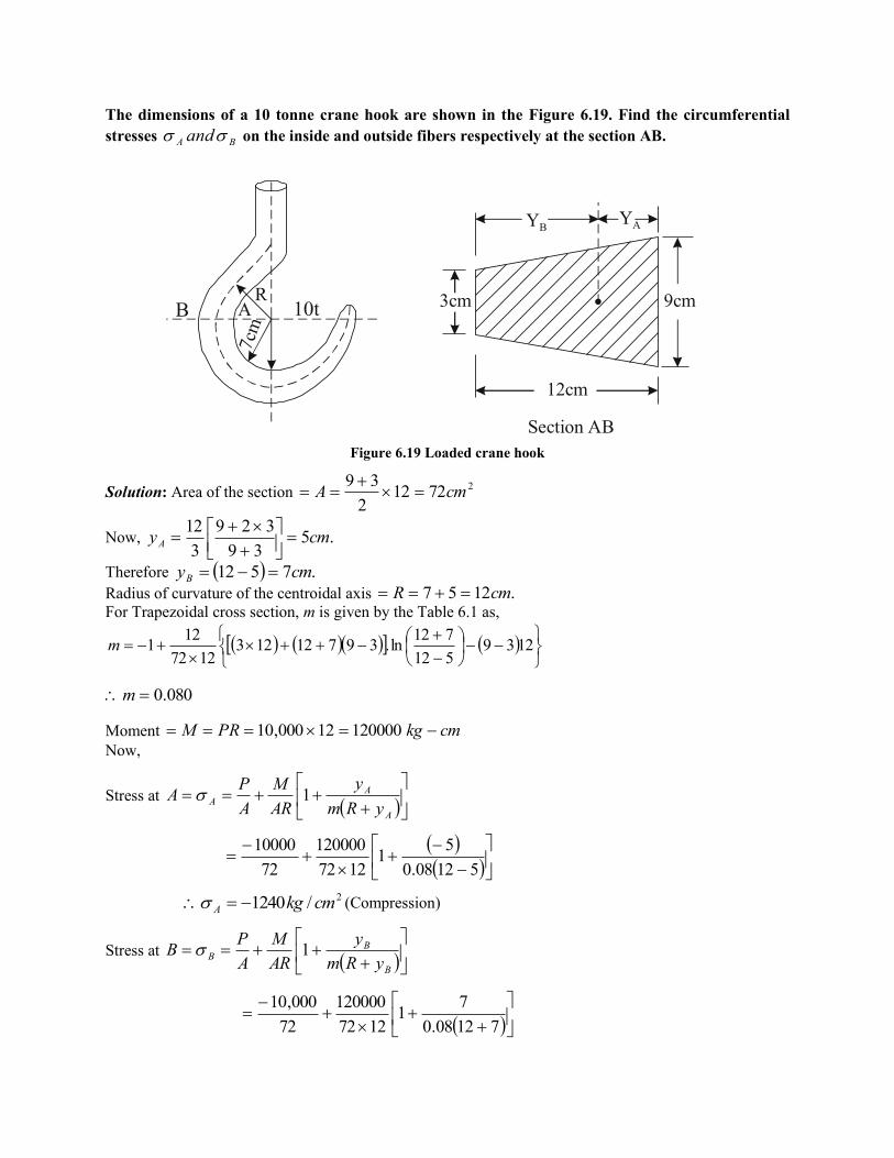
The dimensions of a 10 tonne crane hook are shown in the Figure 6.19. Find the circumferential
stresses BA and on the inside and outside fibers respectively at the section AB.
Figure 6.19 Loaded crane hook
Solution: Area of the section 27212
2
39cmA
Now, .539
329
3
12cmyA
Therefore .7512 cmyB
Radius of curvature of the centroidal axis .1257 cmR
For Trapezoidal cross section, m is given by the Table 6.1 as,
1239
512
712ln.39712123
1272
121m
080.0m
Moment cmkgPRM 12000012000,10
Now,
Stress at
A
AA
yRm
y
AR
M
A
PA 1
51208.0
51
1272
120000
72
10000
2/1240 cmkgA (Compression)
Stress at
B
BB
yRm
y
AR
M
A
PB 1
71208.0
71
1272
120000
72
000,10
7cm
10tA R
B .
12cm
9cm3cm
Y B
Section AB
Y A

2/62.639 cmkgB (Tension)
Example 6.9
A circular open steel ring is subjected to a compressive force of 80 kN as shown
in the Figure 6.20. The cross-section of the ring is made up of an unsymmetrical I-section
with an inner radius of 150mm. Estimate the circumferential stresses developed at points A and B.
Figure 6.20 Loaded circular ring with unsymmetrical I-section
Solution:
From the Table 6.1, the value of m for the above section is given by
cRbcRtbcRbtcRbA
Rm lnlnlnln1 23111
Hence R Radius of curvature of the centroidal axis.
Now, 2600020802012010020 mmA
.33.75
6000
150208080201201020100mmyB
.67.8433.75160 mmyA
Also, .33.22533.75150 mmR
.A B O
150
W
160
. 80 100
160
YBYA
20
20
20R

33.7533.225ln10033.5533.225ln20100
67.6433.225ln802067.8433.225ln80
6000
33.2251m
.072.0m
Moment = .10803.133.225100080 7 mmNPRM
Now, Stress at point
B
BB
yRm
y
AR
M
A
PB 1
33.7533.225072.0
33.751
33.2256000
10803.1
6000
80000 7
B
2/02.93 mmNB (Compression)
Stress at point
A
AA
yRm
y
AR
M
A
PA 1
67.8433.225072.0
67.841
33.2256000
10803.1
6000
80000 7
2/6.50 mmNA (Tension)
Hence, the resultant stresses at A and B are,
2/6.50 mmNA (Tension), 2/02.93 mmNB (Compression)
Example 6.10
Calculate the circumferential stress on inside and outside fibre of the ring at A and B, shown in
Figure 6.21. The mean diameter of the ring is 5cm and cross-section is circular with 2cm diameter.
Loading is within elastic limit.
. R=2.5c
m
Bi
AO
BO
Ai
2P 1000kg=
MA
m
n
P
Pcos
Psin
Ai Ao
P
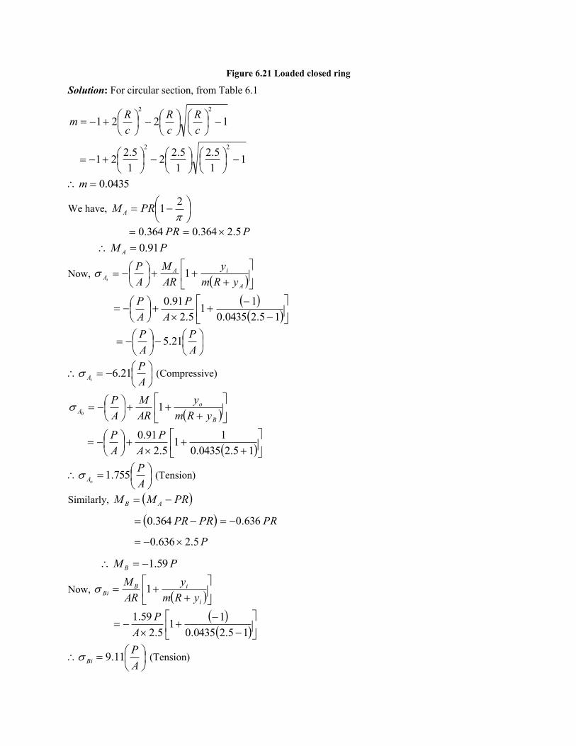
Figure 6.21 Loaded closed ring
Solution: For circular section, from Table 6.1
1221
22
c
R
c
R
c
Rm
11
5.2
1
5.22
1
5.221
22
0435.0m
We have,
21PRM A
PR364.0 P5.2364.0
PM A 91.0
Now,
A
iAA
yRm
y
AR
M
A
Pi
1
15.20435.0
11
5.2
91.0
A
P
A
P
A
P
A
P21.5
A
PiA 21.6 (Compressive)
B
oA
yRm
y
AR
M
A
P1
0
15.20435.0
11
5.2
91.0
A
P
A
P
A
PoA 755.1 (Tension)
Similarly, PRMM AB
PRPR 364.0 PR636.0
P5.2636.0
PM B 59.1
Now,
i
iBBi
yRm
y
AR
M1
15.20435.0
11
5.2
59.1
A
P
A
PBi 11.9 (Tension)
and
15.20435.0
11
5.2
59.1
A
PBo
A
P81.4 (Compression)
Now, substituting the values of ,500kgP
,14159.31 22cmA above stresses can be calculated as below.
2/988500
21.6 cmkgiA
2/32.279500
755.10
cmkgA
2/1450500
11.9 cmkgiB
2/54.765500
81.40
cmkgB
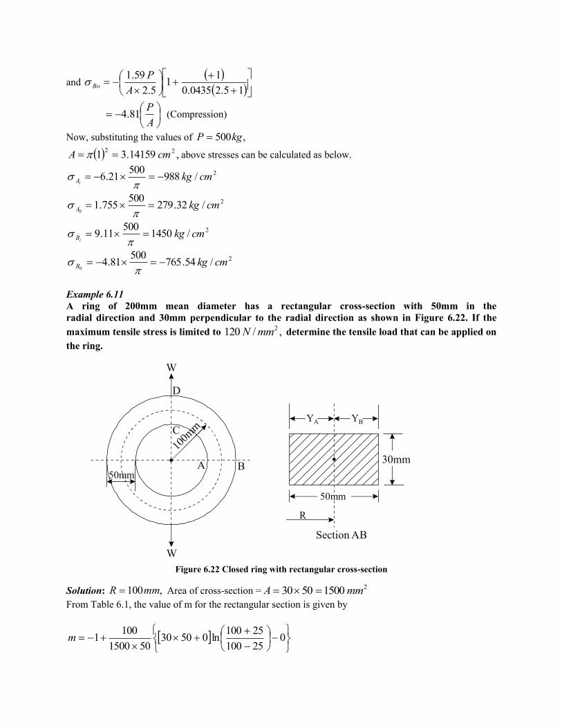
Example 6.11
A ring of 200mm mean diameter has a rectangular cross-section with 50mm in the
radial direction and 30mm perpendicular to the radial direction as shown in Figure 6.22. If the
maximum tensile stress is limited to ,/120 2mmN determine the tensile load that can be applied on
the ring.
Figure 6.22 Closed ring with rectangular cross-section
Solution: ,100mmR Area of cross-section =215005030 mmA
From Table 6.1, the value of m for the rectangular section is given by
0
25100
25100ln05030
501500
1001m
.
W
C
A
100m
m
B
W
D
50mm
.
50mm
YA YB
30mm
R
Section AB

0217.0m
To find ABM
Figure 6.23
The Bending moment at any section MN can be determined by
cos12
WR
MM ABMN
ABmn MMAt ,0
But
21
2
WRM AB
WW
M AB 17.182
12
100
Now,
A
AAA
yRm
y
AR
M
A
P1
A
AA
yRm
y
AR
M
A
W1
2
251000217.0
251
1001500
17.18
15002
WW
WA 002073.0 (Tensile)
W
A B
W2
W2
R M
N
MAB MAB
and
B
BAB
yRm
y
AR
M
A
P1
251000217.0
251
1001500
17.18
15002
Ww
WB 00090423.0 (Compression)
To find stresses at C and D
We have, cos12
WR
MM ABmn
2,900 WR
MMMAt ABCDmn
WWWM CD 83.312
10017.18
Now, stress at
C
CCDC
yRm
y
AR
M
A
PC 1
251000217.0
251
1001500
83.310
W
W00305.0 (Compression)
and stress at
D
DCDD
yRm
y
AR
M
A
PD 1
251000217.0
251
1001500
83.310
W
WD 00217.0 (Tensile)
By comparison, the tensile stress is maximum at Point D.
12000217.0 W kNorNW 3.5554.55299
Example 6.12 A ring of mean diameter 100mm is made of mild steel with 25mm diameter. The ring is subjected to four pulls in two directions at right angles to each other passing through the center of the ring.
Determine the maximum value of the pulls if the tensile stress should not exceed 2/80 mmN

Figure 6.24 Closed ring with circular cross-section
Solution: Here mmR 50
From Table 6.1, the value of m for circular section is given by,
1221
22
C
R
C
R
C
Rm
15.12
50
5.12
502
5.12
5021
22
016.0m
Area of cross-section = 2287.4905.12 mmA
We have,
21
2
WRM A
2150
2
W
WM A 085.9
Now,
A
AAA
yRm
y
AR
M
A
P1
5.1250016.0
5.121
5087.490
085.9
87.4902
WW
.
W
C
A
100m
m B WW
W
D
MAB
M
N
W2
W2
W2
W0084.0 (Tensile)
B
BAB
yRm
y
AR
M
A
P1
5.1250016.0
5.121
5087.490
085.9
87.4902
WW
WB 00398.0 (Compression)
Also,
50
2085.9
WPRMM ACD
WMCD 915.15
Now,
C
CCDC
yRm
y
AR
M1
5.1250016.0
5.121
5087.490
918.15 W
WC 013.0 (Compression)
and
5.1250016.0
5.121
5087.490
918.15 WD
W0088.0 (Tension)
Stresses at Section CD due to horizontal Loads
We have, moment at any section MN is given by
cos12
PR
MM AMN
At section CD, ,0
0cos12
RW
MM ACD
WMM ACD 085.9
C
CCDC
yRm
y
AR
M
A
P1
5.1250016.0
5.121
5087.490
085.9
87.4902
WW
WC 00836.0 (Tensile)
and
D
DCDD
yRm
y
AR
M
A
P1
5.1250016.0
5.121
5087.490
085.9
87.4902
WW
WD 00398.0 (Compression)
Resultant stresses are
WWWC 00464.000836.0013.0 (Compression)
WWWD 00482.000398.00088.0 (Tension)
In order to limit the tensile stress to 2/80 mmN in the ring, the maximum value of the force in the pulls
is given by
0.00482W = 80
kNorNW 598.1651.16597
6.3.5 EXERCISES
1. Is the following function a stress function?
sinrP
If so, find the corresponding stress. What is the problem solved by this function?
2. Investigate what problem of plane stress is solved by the following stress functions
(a) sinrK
P
(b)
sinrP
3. Derive the equilibrium equation for a polar co-ordinate system.
4. Derive the expressions for strain components in polar co-ordinates.
5. Starting from the stress function DCrrBrrA 22 loglog , obtain the stress
components r and in a pipe subjected to internal pressure ip and external pressure
op . Obtain the maximum value of when 0op and indicate where it occurs.
6. Check whether the following is a stress function
tancos2222 rrrc where is a constant.
7. Starting from the stress function 321
8
)3(rC
r
CC rr
, derive expressions for
r and in case of a rotating disk of inner radius 'a' and outer radius 'b'. Obtain the
maximum values of r and .
8. Show that the stress function DCrrBrrA 22 loglog solves the problem of
axisymmetric stress distribution, obtain expressions for r and in case of a pipe
subjected to internal pressure i and external pressure 0 .
9. Show that the following stress function solves the problem of axisymmetric stress
distribution in polar coordinates

DCrrBrrA 22 loglog
10. Explain axisymmetric problems with examples.
11. Derive the general expression for the stress function in the case of axisymmetric stress
distribution.
12. Derive the expression for radial and tangential stress in a thick cylinder subjected to
internal and external fluid pressure.
13. A curved bar bent into a arc of a circle having internal radius ‘a’ and external radius
‘b’ is subjected to a bending couple M at its end. Determine the stresses
,r and r
.
14. For the stress function, rAr log2 , where A is a constant, compute the stress
components ,rand r
.
15. A thick cylinder of inner radius 150mm and outer radius 200mm is subjected to an
internal pressure of 15MN/m2. Determine the radial and hoop stresses in the cylinder at
inner and outer surfaces.
16. The internal and external diameters of a thick hollow cylinder are 80mm and 120mm
respectively. It is subjected to an external pressure of 40MN/m2, when the internal
pressure is 120MN/m2. Calculate the circumferential stresses at the external and internal
surfaces and determine the radial and circumferential stresses at the mean radius.
17. A thick-wall cylinder is made of steel (E = 200GPa and 29.0 ), has an inside
diameter of 20mm, and an outside diameter of 100mm. The cylinder is subjected to an
internal pressure of 300MPa. Determine the stress components r and at
r = a = 10mm, r = 25mm and r = b = 50mm.
18. A long closed cylinder has an internal radius of 100mm and an external radius of 250mm.
It is subjected to an internal pressure of 80MPa. Determine the maximum radial,
circumferential and axial stresses in the cylinder.
19. A solid disc of radius 200mm is rotating at a speed of 3000 rpm. Determine the radial and
hoop stresses in the disc if 3.0 and = 8000kg/m3. Also determine the stresses in
the disc if a hole of 30mm is bored at the centre of the disc.
20. A disc of 250mm diameter has a central hole of 50mm diameter and runs at 4000rpm.
Calculate the hoop stresses. Take 25.0 and = 7800 kg/m3.
21. A turbine rotor 400mm external diameter and 200mm internal diameter revolves at
1000rpm. Find the maximum hoop and radial stresses assuming the rotor to be thin disc.
Take the weight of the rotor as 7700 kg/m3 and poisson’s ratio 0.3.
22. Investigate what problem of plane stress is solved by the following stress function
2
2
3
234
3y
P
C
xyxy
C
F
. Check whether the following is a stress function
2cos2
22
D
r
CBrAr
23. Show that xDyeCyeBeAe yyyy sin represents stress function.
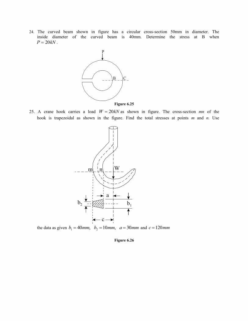
24. The curved beam shown in figure has a circular cross-section 50mm in diameter. The
inside diameter of the curved beam is 40mm. Determine the stress at B when
kNP 20 .
Figure 6.25
25. A crane hook carries a load kNW 20 as shown in figure. The cross-section mn of the
hook is trapezoidal as shown in the figure. Find the total stresses at points m and n. Use
the data as given mmammbmmb 30,10,40 21 and mmc 120
Figure 6.26
B
P
C
W
a
b2 b1
c
m n
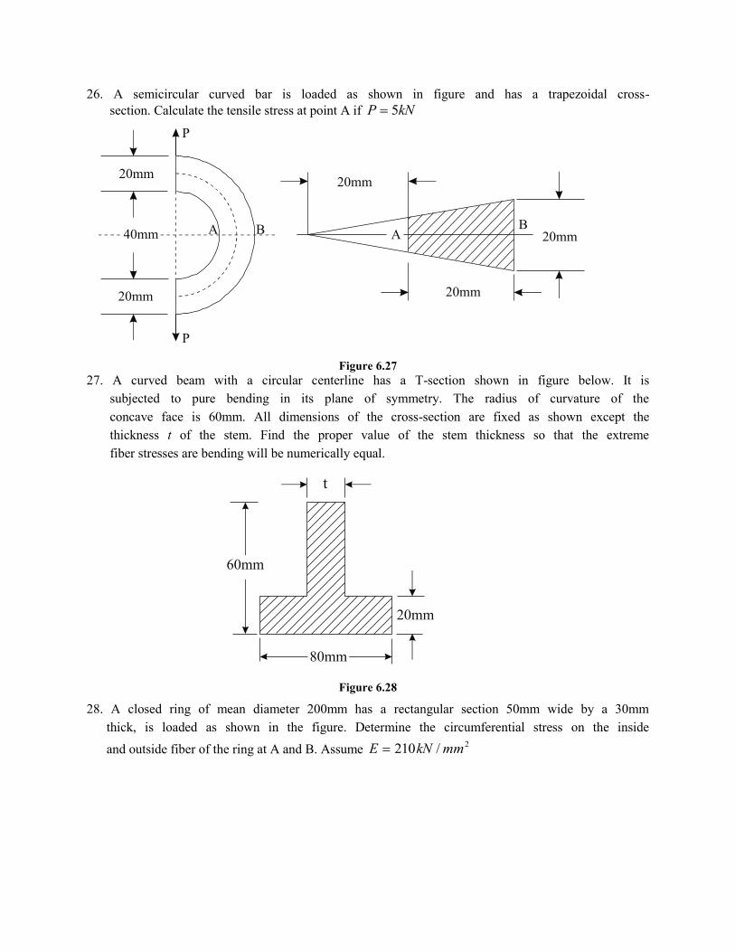
26. A semicircular curved bar is loaded as shown in figure and has a trapezoidal cross-
section. Calculate the tensile stress at point A if kNP 5
Figure 6.27
27. A curved beam with a circular centerline has a T-section shown in figure below. It is
subjected to pure bending in its plane of symmetry. The radius of curvature of the
concave face is 60mm. All dimensions of the cross-section are fixed as shown except the
thickness t of the stem. Find the proper value of the stem thickness so that the extreme
fiber stresses are bending will be numerically equal.
Figure 6.28
28. A closed ring of mean diameter 200mm has a rectangular section 50mm wide by a 30mm
thick, is loaded as shown in the figure. Determine the circumferential stress on the inside
and outside fiber of the ring at A and B. Assume 2/210 mmkNE
60mm
80mm
20mm
t
20mm
40mm A B
P
P
20mm
A B
20mm
20mm
20mm
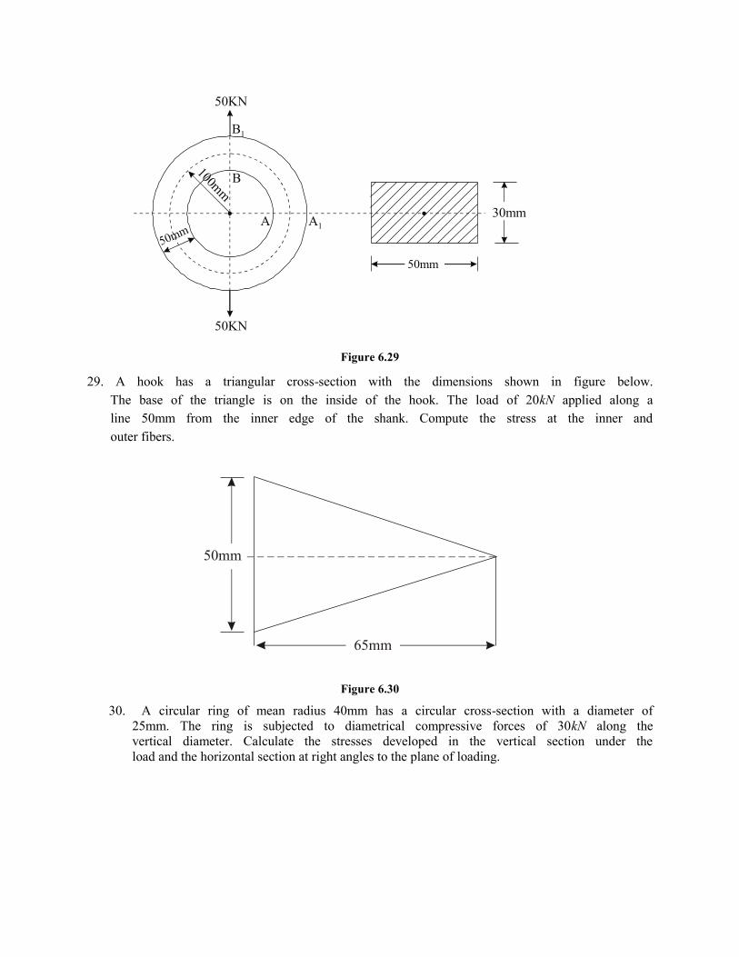
Figure 6.29
29. A hook has a triangular cross-section with the dimensions shown in figure below.
The base of the triangle is on the inside of the hook. The load of 20kN applied along a
line 50mm from the inner edge of the shank. Compute the stress at the inner and
outer fibers.
Figure 6.30
30. A circular ring of mean radius 40mm has a circular cross-section with a diameter of
25mm. The ring is subjected to diametrical compressive forces of 30kN along the
vertical diameter. Calculate the stresses developed in the vertical section under the
load and the horizontal section at right angles to the plane of loading.
.A
100mm
B
50mm
.
50mm
30mmA1
B1
50KN
50KN
65mm
50mm
Related Documents


