6.270 Course Notes by Michael S. Allen Submitted to the Department of Electrical Engineering and Computer Science in partial fulfillment of the requirements for the degree of Master of Engineering in Electrical Engineering and Computer Science at the MASSACHUSETTS INSTITUTE OF TECHNOLOGY MASSACHUSETTS INSTITUTE May 1999 OF TECHNOLOGY @Michael Allen 1999. All rights reserved. 1 5 1999 The author hereby grants to M.I.T. permission to reprodace ) ES and distribute publicly paper and electronic copies of this thesis and to grant others the right to do so. Author ............................................... Department of Electrical Engineering and Computer Science May 24, 1999 Certified by ........................ .. Gill A. Pratt Assistant Professor Thesis Supervisor .9 7 Accepted by............ Arthur C. Smith Chairman, Department Committee on Graduate Students

Welcome message from author
This document is posted to help you gain knowledge. Please leave a comment to let me know what you think about it! Share it to your friends and learn new things together.
Transcript
6.270 Course Notes
by
Michael S. Allen
Submitted to the Department of Electrical Engineering andComputer Science
in partial fulfillment of the requirements for the degree of
Master of Engineering in Electrical Engineering and ComputerScience
at the
MASSACHUSETTS INSTITUTE OF TECHNOLOGYMASSACHUSETTS INSTITUTE
May 1999 OF TECHNOLOGY
@Michael Allen 1999. All rights reserved. 1 5 1999
The author hereby grants to M.I.T. permission to reprodace ) ESand distribute publicly paper and electronic copies ofthis thesis and to grant others the right to do so.
Author ...............................................
Department of Electrical Engineering and Computer ScienceMay 24, 1999
Certified by ........................ ..Gill A. Pratt
Assistant ProfessorThesis Supervisor
.97
Accepted by............Arthur C. Smith
Chairman, Department Committee on Graduate Students

MIT LibrariesDocument Services
Room 14-055177 Massachusetts AvenueCambridge, MA 02139Ph: 617.253.2800Email: [email protected]://libraries.mit.edu/docs
DISCLAIM ER
Only a few selected pages have beennumbered by the author.
6.270 Course Notes
by
Michael S. Allen
Submitted to the Department of Electrical Engineering and Computer Scienceon May 24, 1999, in partial fulfillment of the
requirements for the degree ofMaster of Engineering in Electrical Engineering and Computer Science
Abstract
MIT's 6.270 Autonomous Robot Design Competition is a student-run learn-by-doingclass held during the Independent Activities Period (IAP). At the beginning of theclass, students receive a kit containing LEGO pieces, a microprocessor-based con-troller, and assorted electronic components. They then have approximately threeweeks to produce a robot to compete in the competition.
The primary purpose of this thesis is to produce a new and improved set of coursenotes to incorporate ideas both new and old. In the years since the creation of theprevious course notes, the course has evolved substantially, but the course notes havenot been updated. This has caused ideas to be lost and the notes to become stale. Ihave gathered and incorporated much of this lost information into the notes, as wellas adding new information based on my own experiences with the course.
The chapters contained herein are meant to replace and add to the material alreadycontained in the notes. As part of the book, they will become part of an evolvingwork until they are replaced by future contest organizers.
Thesis Supervisor: Gill A. PrattTitle: Assistant Professor
Acknowledgements
In my junior year as an undergrad at MIT, I participated in the 6.270 Autonomous
Robot Design Competition. At the time, I thought it was a lot of fun and even a bit
educational. I had no idea that I it was about to change my life.
6.270 was my first experience with robotics, and it did not take me long to figure
out that I should be in that field. So, the next year, I came back and volunteered
to help organize the contest. At first, I was inexperienced and overwhelmed, but the
other organizers quickly brought me up to speed.
The next year, I became even more involved. With a year of experience under my
belt, I was more confident and able to take on larger projects. One of the projects
that fell to me was teaching. I had taught students before, but this was the first time
that I was in charge of the class. It was around this time that I realized my life's
purpose as a teacher.
The completion of this thesis corresponds to the end of my third year as an
organizer, and possibly the end of my involvement in 6.270. Looking back, I remember
numerous people and stories who have influenced the direction that my life is now
taking. My work with 6.270 has made me a better person and brought me into contact
with some wonderful people. Among these people, I would like to acknowledge the
following:
" The contest organizers past and present for their tireless devotion to doing
whatever it takes to make 6.270 happen. I have never met a group willing to do
so much for such a small reward just because they believe that someone should
do it.
" The TAs past and present without whom the organizers would not have enough
manpower to make the contest happen.
" The participants past and present for their enthusiasm. Without them, 6.270
would not have a reason for being.
" Gill Pratt, 6.270's faculty advisor, who is always there when needed, but trusts
the organizers to do it on their own.
" The faculty and staff of the EECS department who go out of their way to help
a bunch of students run their little activity.
" Everyone else who has ever helped to make 6.270 a reality.
Contents
1 Introduction to 6.270 12
1.1 Staff . . . . . . . . . . . . . . . . . . . . . . . . . . . . . . . . . . . . 13
1.2 Kits and Tools . . . . . . . . . . . . . . . . . . . . . . . . . . . . . . 14
1.3 Electronic Communication . . . . . . . . . . . . . . . . . . . . . . . . 14
1.3.1 Mailing Lists . . . . . . . . . . . . . . . . . . . . . . . . . . . 14
1.3.2 Zephyr Instance . . . . . . . . . . . . . . . . . . . . . . . . . . 15
1.4 Laboratory Facilities . . . . . . . . . . . . . . . . . . . . . . . . . . . 16
1.4.1 6th Floor Laboratory . . . . . . . . . . . . . . . . . . . . . . . 16
1.4.2 Other Facilities . . . . . . . . . . . . . . . . . . . . . . . . . . 16
1.4.3 Etiquette . . . . . . . . . . . . . . . . . . . . . . . . . . . . . 17
1.5 Credit Guidelines . . . . . . . . . . . . . . . . . . . . . . . . . . . . . 18
1.5.1 Academic Credit . . . . . . . . . . . . . . . . . . . . . . . . . 18
1.5.2 Engineering Design Points . . . . . . . . . . . . . . . . . . . . 20
1.6 Schedule . . . . . . . . . . . . . . . . . . . . . . . . . . . . . . . . . . 21
1.6.1 Important Dates . . . . . . . . . . . . . . . . . . . . . . . . . 22
1.6.2 Syllabus . . . . . . . . . . . . . . . . . . . . . . . . . . . . . . 23
2 Raiders of the Lost Parts 29
2.1 The Table . . . . . . . . . . . . . . . . . . . . . . . . . . . . . . . . . 30
5
2.2 Scoring . . . . . . . .
2.3 The Competition . .
2.4 Rules . . . . . . . . .
2.4.1 Period of Play
2.4.2 Kits . . . . .
2.4.3 Robots . . . .
2.4.4 LEGO . . . .
2.4.5 Software . . .
2.4.6 Non-LEGO pa
2.4.7 Infrared Beaco
2.4.8 Placebos . . .
2.5 Extra Electronics . .
2.5.1 The Sensor St
irts
nf and
ore
Light
2.5.2 $20 Electronics Rule
3 The Human Factor
3.1 Survival Tips . . . . . . . .
3.2 Teamwork . . . . . . . . . .
3.2.1 Planning . . . . . . .
3.2.2 Brainstorming . . . .
3.2.3 Constructive Conflict
3.2.4 Friends and Enemies
3.3 Implementation . . . . . . .
3.3.1 Division of Labor . .
3.3.2 Debugging . . . . . .
3.4 Contest Tips . . . . . . . . .
Sources
31
32
33
33
34
34
35
36
36
37
38
38
38
38
40
40
42
42
43
43
44
45
45
46
47
4 Electronic Assembly
4.1 Soldering ............
4.1.1 Safety .........
4.1.2 Technique . . . . . . .
4.1.3 Mounting Components
4.1.4 Desoldering . . . . . .
4.2 Components . . . . . . . . . .
4.2.1 Resistors . . . . . . . .
4.2.2 Resistor Packs .....
4.2.3 Capacitors . . . . . . .
4.2.4 Diodes and LEDs
4.2.5 Integrated Circuits
4.3 Connectors . . . . . . . . . .
4.4 M otors . . . . . . . . . . . . .
4.5 Servo .
5 Sensors
5.1 Digital Sensors . . . . . . . . . . .
5.1.1 Switches and buttons . . . .
5.1.2 Sharp IR . . . . . . . . . . .
5.2 Resistive Analog Sensors . . . . . .
5.2.1 Potentiometers . . . . . . .
5.2.2 CDS Cell . . . . . . . . . .
5.3 Transistive Analog Sensors . . . . .
5.3.1 Bundle of Wires . . . . . . .
5.3.2 Breakbeam Sensor Package .
5.3.3 Reflectance Sensor Package
48
. . . . . 48
. . . . . 49
. . . . . 49
. . . . . 51
. . . . . 52
. . . . . 53
. . . . . 54
. . . . . 55
. . . . . 56
. . . . . 57
. . . . . 57
. . . . . 58
. . . . . 60
62
63
64
64
66
67
68
69
69
70
72
73
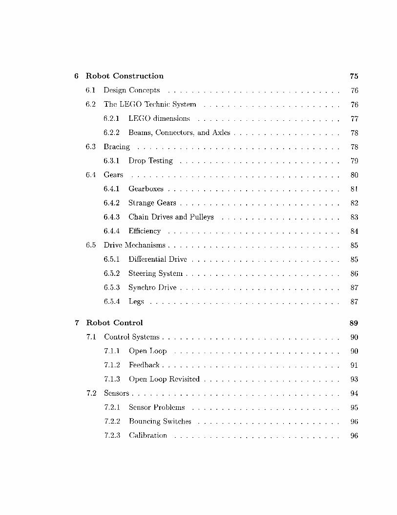
6 Robot Construction 75
6.1 Design Concepts . . . . . . . . . . . . . . . . . . . . . . . . . . . . . 76
6.2 The LEGO Technic System . . . . . . . . . . . . . . . . . . . . . . . 76
6.2.1 LEGO dimensions . . . . . . . . . . . . . . . . . . . . . . . . 77
6.2.2 Beams, Connectors, and Axles . . . . . . . . . . . . . . . . . . 78
6.3 B racing . . . . . . . . . . . . . . . . . . . . . . . . . . . . . . . . . . 78
6.3.1 Drop Testing . . . . . . . . . . . . . . . . . . . . . . . . . . . 79
6.4 G ears . . . . . . . . . . . . . . . . . . . . . . . . . . . . . . . . . . . 80
6.4.1 Gearboxes ...... ..... . . . . .. . . . . . ... .. ... 81
6.4.2 Strange Gears .... . ....... . . . . .. . . . . .. . . . . 82
6.4.3 Chain Drives and Pulleys . . . . . . . . . . . . . . . . . . . . 83
6.4.4 Efficiency .. ... . . . . . . . . . . . . . . . . . . .. . . . . 84
6.5 Drive Mechanisms.. ... . . . . . . . . . . . . . . . . . . . . . . . . 85
6.5.1 Differential Drive . . . . . . . . . . . . . . . . . . . . . . . . . 85
6.5.2 Steering System... ........... . . . . . . . . .... . . . . 86
6.5.3 Synchro Drive... . . . . . . . . . . . . . . . . . . . . . . . . 87
6.5.4 L egs . . . . . . . . . . . . . . . . . . . . . . . . . . . . . . . . 87
7 Robot Control 89
7.1 Control Systems . . . . . . . . . . . . . . . . . . . . . . . . . . . . . . 90
7.1.1 Open Loop . . . . . . . . . . . . . . . . . . . . . . . . . . . . 90
7.1.2 Feedback . . . . . . . . . . . . . . . . . . . . . . . . . . . . . . 91
7.1.3 Open Loop Revisited . . . . . . . . . . . . . . . . . . . . . . . 93
7.2 Sensors . . . . . . . . . . . . . . . . . . . . . . . . . . . . . . . . . . . 94
7.2.1 Sensor Problems . . . . . . . . . . . . . . . . . . . . . . . . . 95
7.2.2 Bouncing Switches . . . . . . . . . . . . . . . . . . . . . . . . 96
7.2.3 Calibration . . . . . . . . . . . . . . . . . . . . . . . . . . . . 96
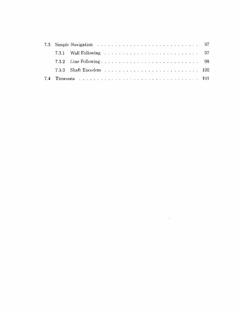
7.3 Simple Navigation . .
7.3.1 Wall Following
7.3.2 Line Following.
7.3.3 Shaft Encoders
7.4 Timeouts . . . . . . .
97
97
98
100
101
. . . . . . . . . . . . . . . . . . . . . . . . . .
. . . . . . . . . . . . . . . . . . . . . . . . . .
. . . . . . . . . . . . . . . . . . . . . . . . . .
. . . . . . . . . . . . . . . . . . . . . . . . . .
. . . . . . . . . . . . . . . . . . . . . . . . . .
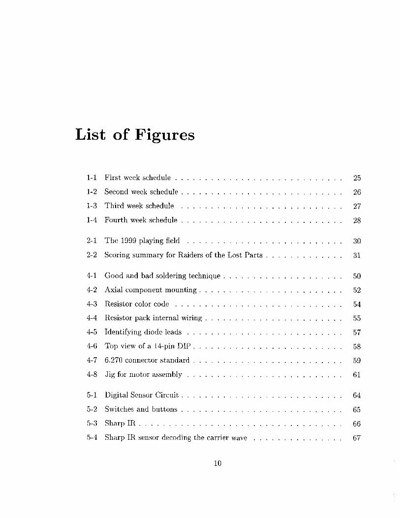
List of Figures
1-1
1-2
1-3
1-4
First week schedule .
Second week schedule
Third week schedule
Fourth week schedule
2-1 The 1999 playing field . . . . . . . . . . . . .
2-2 Scoring summary for Raiders of the Lost Parts
4-1 Good and bad soldering technique . . . . . . .
4-2 Axial component mounting . . . . . . . . . . .
4-3 Resistor color code . . . . . . . . . . . . . . .
4-4 Resistor pack internal wiring . . . . . . . . . .
4-5 Identifying diode leads . . . . . . . . . . . . .
4-6 Top view of a 14-pin DIP . . . . . . . . . . . .
4-7 6.270 connector standard . . . . . . . . . . . .
4-8 Jig for motor assembly . . . . . . . . . . . . .
5-1
5-2
5-3
Digital Sensor Circuit . . .
Switches and buttons . . .
Sharp IR . . . . . . . . . .
5-4 Sharp IR sensor decoding the carrier wave . . . . . . . . . . . . . . .
10
25
26
27
28
30
31
50
52
54
55
57
58
59
61
. . . . . . . . . . . . . . . . . . . . . . . . 6 4
.. ... ..... ... .. .. .. ... .. 6 5
.. ... ..... ... .. .. .. ... .. 6 6
67
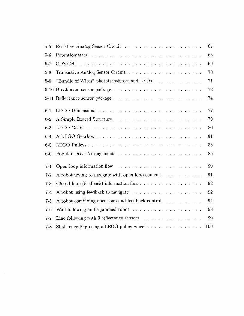
5-5 Resistive Analog Sensor Circuit . . . . . . . .
5-6 Potentiometers . . . . . . . . . . . . . . . . .
5-7 CD S Cell . . . . . . . . . . . . . . . . . . . .
5-8 Transistive Analog Sensor Circuit . . . . . . .
5-9 "Bundle of Wires" phototransistors and LEDs
5-10 Breakbeam sensor package . . . . . . . . . . .
5-11 Reflectance sensor package ... ..........
6-1 LEGO Dimensions.....
6-2 A Simple Braced Structure
6-3 LEGO Gears . . . . . . . .
6-4 A LEGO Gearbox . . . . . .
6-5 LEGO Pulleys . . . . . . . .
6-6 Popular Drive Arrangements
7-1 Open loop information flow
7-2
7-3
7-4
7-5
7-6
7-7
7-8
A robot trying to navigate wi
Closed loop (feedback) inform
A robot using feedback to na'
A robot combining open loop
Wall following and a jammed
Line following with 3 reflecta
Shaft encoding using a LEGC
. . . . . . . . . . . . . . . . . . . . . . . 7 7
. . . . . . . . . . . . . . . . . . . . . . . 7 9
. . . . . . . . . . . . . . . . . . . . . . . 8 0
. . . . . . . . . . . . . . . . . . . . . . . 8 1
. ... .. ... ... ... ... . .... 8 3
. .. ... .. .... .. ... .. .... 8 5
. .. ... .. .... .. ... .. .... 9 0
th open loop control . . . . . . . . . . . 91
ation flow . . . . . . . . . . . . . . . . . 92
vigate . . . . . . . . . . . . . . . . . . . 92
and feedback control . . . . . . . . . . 94
robot . . . . . . . . . . . . . . . . . . . 98
nice sensors . . . . . . . . . . . . . . . . 99
pulley wheel . . . . . . . . . . . . . . . 100
67
68
69
70
71
72
74
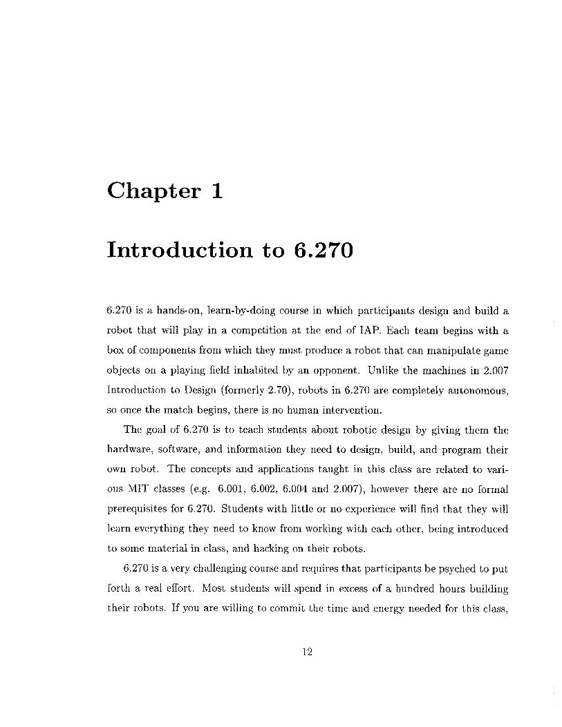
Chapter 1
Introduction to 6.270
6.270 is a hands-on, learn-by-doing course in which participants design and build a
robot that will play in a competition at the end of IAP. Each team begins with a
box of components from which they must produce a robot that can manipulate game
objects on a playing field inhabited by an opponent. Unlike the machines in 2.007
Introduction to Design (formerly 2.70), robots in 6.270 are completely autonomous,
so once the match begins, there is no human intervention.
The goal of 6.270 is to teach students about robotic design by giving them the
hardware, software, and information they need to design, build, and program their
own robot. The concepts and applications taught in this class are related to vari-
ous MIT classes (e.g. 6.001, 6.002, 6.004 and 2.007), however there are no formal
prerequisites for 6.270. Students with little or no experience will find that they will
learn everything they need to know from working with each other, being introduced
to some material in class, and hacking on their robots.
6.270 is a very challenging course and requires that participants be psyched to put
forth a real effort. Most students will spend in excess of a hundred hours building
their robots. If you are willing to commit the time and energy needed for this class,
12
you will have a great time and even learn something along the way. So, prepare
yourself for three and a half weeks of immersion into the world of robotics. There is
no time to waste... Welcome to 6.270.
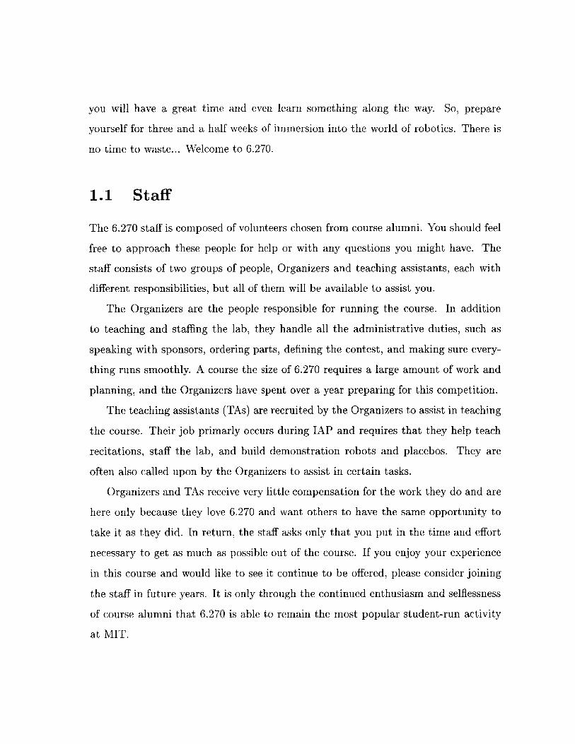
1.1 Staff
The 6.270 staff is composed of volunteers chosen from course alumni. You should feel
free to approach these people for help or with any questions you might have. The
staff consists of two groups of people, Organizers and teaching assistants, each with
different responsibilities, but all of them will be available to assist you.
The Organizers are the people responsible for running the course. In addition
to teaching and staffing the lab, they handle all the administrative duties, such as
speaking with sponsors, ordering parts, defining the contest, and making sure every-
thing runs smoothly. A course the size of 6.270 requires a large amount of work and
planning, and the Organizers have spent over a year preparing for this competition.
The teaching assistants (TAs) are recruited by the Organizers to assist in teaching
the course. Their job primarly occurs during IAP and requires that they help teach
recitations, staff the lab, and build demonstration robots and placebos. They are
often also called upon by the Organizers to assist in certain tasks.
Organizers and TAs receive very little compensation for the work they do and are
here only because they love 6.270 and want others to have the same opportunity to
take it as they did. In return, the staff asks only that you put in the time and effort
necessary to get as much as possible out of the course. If you enjoy your experience
in this course and would like to see it continue to be offered, please consider joining
the staff in future years. It is only through the continued enthusiasm and selflessness
of course alumni that 6.270 is able to remain the most popular student-run activity
at MIT.
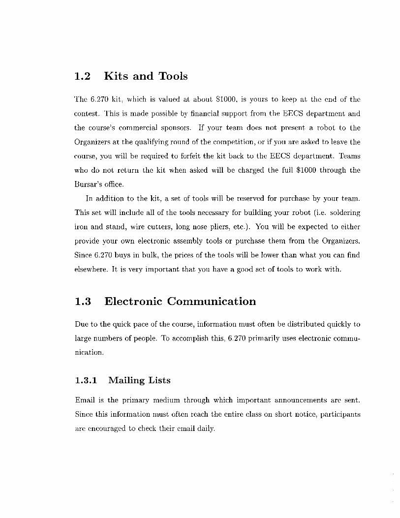
1.2 Kits and Tools
The 6.270 kit, which is valued at about $1000, is yours to keep at the end of the
contest. This is made possible by financial support from the EECS department and
the course's commercial sponsors. If your team does not present a robot to the
Organizers at the qualifying round of the competition, or if you are asked to leave the
course, you will be required to forfeit the kit back to the EECS department. Teams
who do not return the kit when asked will be charged the full $1000 through the
Bursar's office.
In addition to the kit, a set of tools will be reserved for purchase by your team.
This set will include all of the tools necessary for building your robot (i.e. soldering
iron and stand, wire cutters, long nose pliers, etc.). You will be expected to either
provide your own electronic assembly tools or purchase them from the Organizers.
Since 6.270 buys in bulk, the prices of the tools will be lower than what you can find
elsewhere. It is very important that you have a good set of tools to work with.
1.3 Electronic Communication
Due to the quick pace of the course, information must often be distributed quickly to
large numbers of people. To accomplish this, 6.270 primarily uses electronic commu-
nication.
1.3.1 Mailing Lists
Email is the primary medium through which important announcements are sent.
Since this information must often reach the entire class on short notice, participants
are encouraged to check their email daily.
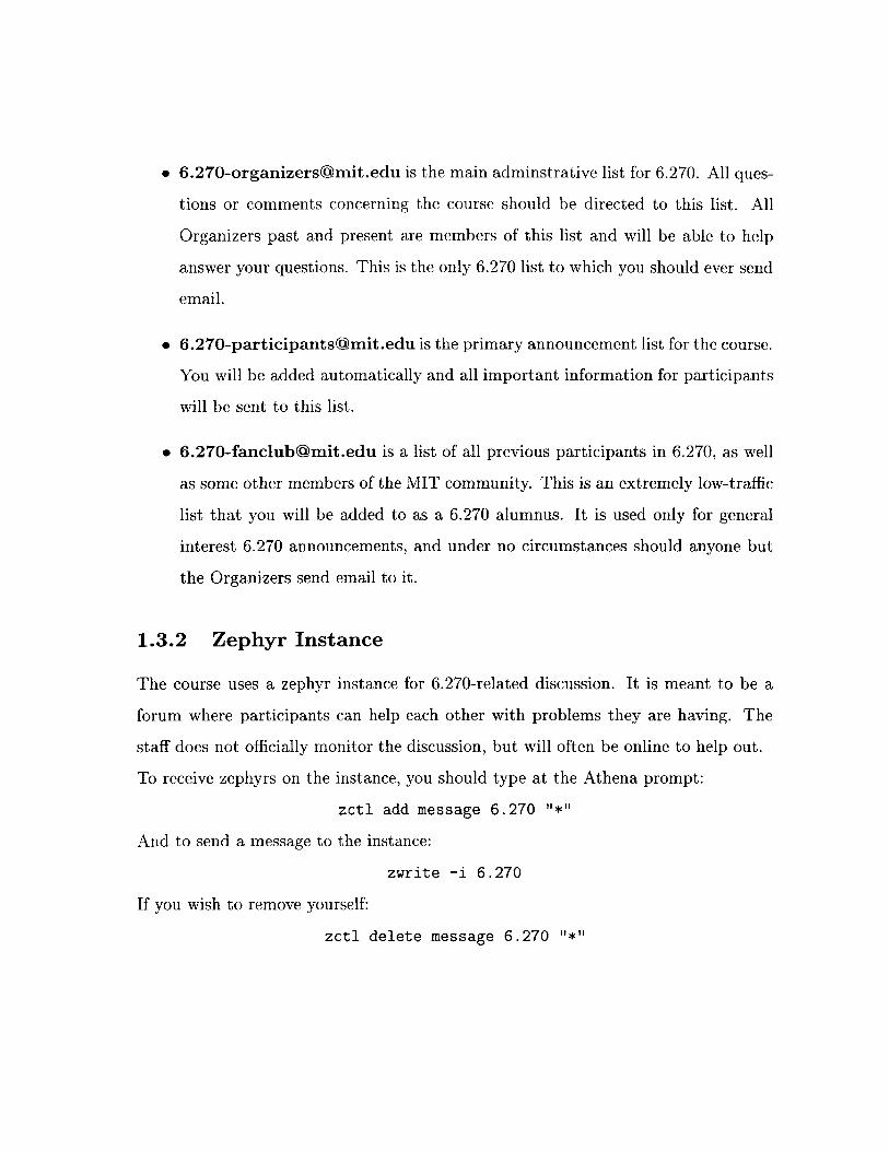
* 6.270-organizers(mit.edu is the main adminstrative list for 6.270. All ques-
tions or comments concerning the course should be directed to this list. All
Organizers past and present are members of this list and will be able to help
answer your questions. This is the only 6.270 list to which you should ever send
email.
* 6.270-participants~mit.edu is the primary announcement list for the course.
You will be added automatically and all important information for participants
will be sent to this list.
* [email protected] is a list of all previous participants in 6.270, as well
as some other members of the MIT community. This is an extremely low-traffic
list that you will be added to as a 6.270 alumnus. It is used only for general
interest 6.270 announcements, and under no circumstances should anyone but
the Organizers send email to it.
1.3.2 Zephyr Instance
The course uses a zephyr instance for 6.270-related discussion. It is meant to be a
forum where participants can help each other with problems they are having. The
staff does not officially monitor the discussion, but will often be online to help out.
To receive zephyrs on the instance, you should type at the Athena prompt:
zctl add message 6.270 "
And to send a message to the instance:
zwrite -i 6.270
If you wish to remove yourself:
zctl delete message 6.270 "
1.4 Laboratory Facilities
During the course of constructing your robot, you will need access to the appropriate
workspaces, tools, and computers. These will all be made available to you by the
course.
1.4.1 6th Floor Laboratory
The 6th floor lab (Room 38-600) is the center of activity for the course. This lab is
supervised by the 6.270 staff, and other teams will be present to share ideas with.
Among the useful facilities in this lab are workbenches for building your robot, com-
puters for programming, and contest tables for testing.
The lab will be open and staffed from 10am to 11:45pm on weekdays and noon to
9:45pm on weekends. During the final few days of the course, the lab may be open
24 hours a day. If you need to call the lab, the phone number is x3-7350, but please
do not place or receive personal calls too often. The phone line needs to be kept
available for official use, and the staff is too busy to run a personal messaging service.
Since this lab is on loan to 6.270 by the EECS department, you will be expected
to be on your best behavior. Do not touch equipment not explicitly meant for 6.270
use and treat the lab staff with respect. Be aware that when the equipment desk
workers are ready to close the lab, you should be going out the door. Abuse of the
lab or its staff will not be tolerated.
1.4.2 Other Facilities
If you have the appropriate cable, you can also program your robot at most Athena
workstations. You may not, however, solder, cut, or glue in the clusters, and you must
be respectful of others when operating your robot, since robots can be quite loud.
Violations of Athena etiquette will result in severe action by the 6.270 Organizers.
Since the course software is available for a number of computer platforms, some
students choose also to program their robots from their own computers. Teams with
access to laptops may find this option especially useful even when working in the lab,
since it frees them from waiting for the lab computers. Unfortunately, due to the
staff's limited amount of time, technical support for personal computers must take
low priority with respect to other duties.
1.4.3 Etiquette
When working in the lab or at Athena, you will be expected to be respectful to those
around you. The following guidelines should be adhered to at all times:
1. Noise. Your robot will be quite noisy. When working at Athena, please min-
imize the operation of your robot. If others are disturbed by the noise, stop
running the robot or move to another cluster.
2. Hardware. Do not solder, cut, or glue any hardware in the clusters or around
the computers in lab. Debris can get lodged in the keyboards and damage the
computer.
3. Tidiness. Do not leave your stuff laying around lab. The lab will be crowded
and people need places to work. Your team should try to limit the area that it
uses to two workbenches, or one if the lab is very crowded.
4. Locked Screens. At Athena, do not leave your screen locked for more than 20
minutes. In lab, any computer with a locked screen will be rebooted. Repeated
violations will result in a loss of computer priviledges.
5. Multiple Machines. Do not log on at multiple machines. When the lab is
crowded, please try also to minimize the number of people on your team who
are logged on. The lab does not have enough computers to support everyone
being logged on at once.
Violations of the rules of etiquette will not be tolerated and will be dealt with
severely. If the Organizers receive complaints about any team causing a disturbance
in the Athena clusters, that team will be required to return its kit and will be thrown
out of the course. Repeated violations in lab will be dealt with by the Organizers on
a case by case basis.
1.5 Credit Guidelines
6.270 is offered as MIT subject 6.190 for six units of Pass/No Record credit with the
further option to receive six Engineering Design Points (EDPs). Taking the course
for credit is optional, but you will be doing a lot of work anyway. Receiving credit
will give you formal recognition on your transcript in addition to the academic credit.
It is the job of the instructors to ensure that credit is properly awarded to students
deserving of it. In order to properly evaluate your performance, it is necessary that
you report your work. The credit requirements are structured to allow your instructor
to authorize credit and also assist you in the learning process.
1.5.1 Academic Credit
The following guidelines must be completed in order to receive six units of academic
credit:
* Individual Design Notebook. Each individual desiring credit must turn in
a separate design notebook detailing the design and construction of the robot.
This is meant to help you with your thought process, as well as to give your
instructor a sense of what you have contributed to the design. You should
make entries in your notebook every day or every other day. Notebooks should
include, but not be limited to, the following information:
- your contributions to the robot
- strategies that your team has considered
- details about the robot's construction and programming (drawings are a
good way to show this)
- problems you may have encountered
- your evaluation of and suggestions for improving 6.270
Notebooks must be submitted on Thursday, January 28th. After they have
been evaluated, they will be returned to you.
" Robot Web Page. Each team must create a web page for its robot before
impounding. The page should present information about the robot suitable for
display to the general public. It should focus on the overall design and strategy
of the robot including an explanation of anything particularly clever or unique.
Each individual desiring credit must help with the work.
" Recitation Attendance. You may only miss one meeting of your recitation
section if you wish to receive credit. If an absence is unavoidable, please speak
to your recitation leader ahead of time.
" Completed Robot. Your team must "show" a robot at the qualifying round.
Its functionality, or lack thereof, has no effect on your receiving credit for the
work you have done.
These requirements are meant to be useful to both you, the class participant, and
the instructors, who will be authorizing credit. You should have no trouble receiving
credit if all of the requirements are satisfied. If you have any questions about your
standing in the subject at any time, feel free to ask your instructor for feedback.
Please note that due to the scheduling constraints of the Registrar and
the sanity of the Organizers, there is no leeway on any of the due dates.
Please do not ask for extensions.
1.5.2 Engineering Design Points
Since design is a very important factor in 6.270, the EECS department offers 6 En-
gineering Design Points for EECS students who take the course. In order to receive
these points, however, you must complete a few additional requirements.
First, you must complete all of the above requirements and receive academic credit
for the course. Then, after the course, you must write a technical paper evaluating
your robot. This paper must be 5 to 10 pages long and should be submitted by
Monday, February 22nd. Writing this paper should be an individual effort and should
include, but not be limited to, the following information:
" a description of the design of your robot (drawings are a good way to show this)
" an evaluation of your robot's performance
" your individual redesign of the robot (i.e. If you were given the opportunity to
retake the course with the same goals, how would your robot be different?)
* an evaluation of the contest and suggestions for improvement
1.6 Schedule
The schedule of activities between the start of 6.270 and the evening of the contest
is very tight. You will have to work steadily and with determination to produce a
working robot by the end of the course. To assist you in this endeavor, a number of
class meetings will be held to teach the course material. It is recommended that you
attend as many of these sessions as possible.
" General Lectures. Lectures will be held during the first week of the course
to introduce you to the basics of robotics. These lectures are meant to provide
you with an overview of the information necessary to create a working 6.270
robot.
" Recitations. Recitations will each consist of about 6 teams and will cover
material in more depth than the lectures. These meetings will focus on group
discussion and the sharing of ideas. Each recitation will be led by an Organizer-
TA team who will share their experiences with you and help you in building
your robot. Many of the recitations will have hands-on experiments and will
require you to bring your kit. Note that recitation attendance is mandatory for
those taking the course for credit.
" Laboratory Sessions. Staff members will be present in the 6th floor lab to
assist you in the construction of your robot. One of the goals of 6.270 is to
encourage interaction, and the lab is a great place to share ideas with others
and experiment with ideas you may not have thought of.
" Workshops. If enough participants are interested, workshops may be taught by
experienced staff members. These workshops can cover anything from soldering
to programming to construction. If you believe that a workshop on a particular
topic would be especially helpful, feel free to suggest it to an Organizer.
1.6.1 Important Dates
While it is important that you attend all of the scheduled 6.270 events, the following
meetings are mandatory and should not be missed:
" Parts Sorting Session - Sunday, January 3rd, 1pm, Room 38-600
Each team must provide one person-hour of manual labor helping to sort out
the kit parts. Usually, this session is a lot of fun as you get to meet other people
in the class and see all the kit parts.
" First Lecture - Monday, January 4th, 10am, Room 34-101
Each team must have at least 50% of its members present to claim the kit.
" Qualifying - Monday, January 25th, 6pm, Room 26-100
All robots must compete in the first round in order to qualify for the remainder
of the contest. This event is open to the public.
" Impounding - Tuesday, January 26th, 6pm, Room 38-600
All work on robots must cease and robots will be impounded. During this time,
robots will be inspected for rule violations.
" 2nd Round - Wednesday, January 27th, 11am, Room 26-100
All qualifying robots will compete in this round. This event is open to the public.
This round may be cancelled if few enough robots qualify for the competition.
" Main Competition - Wednesday, January 27th, 6pm, Room 26-100
The main competition. Robots will compete until a winner is decided. This
event is open to the public.
" Lab Cleanup - Thursday, January 28th, noon, Room 38-600
Attendance at this session is mandatory. Each team must provide one person-
hour of manual labor helping to clean up the lab, so we can give it back to 6.111
the way we found it.
1.6.2 Syllabus
Lectures and recitations will be the primary way that material is taught, so attendance
at these sessions is very important. The following topics will be covered:
" Lecture 1 - Monday, January 4th, 10am, Room 34-101
General information, contest rules, teamwork, strategy, and kit distribution.
" Recitation 1 - Tuesday, January 5th
Brainstorming and discussion of potential strategies.
" Lecture 2 - Wednesday, January 6th, 3pm, Room 34-101
Using sensors and building robots out of Lego.
* Recitation 2 - Thursday, January 7th
Building robots and LEGO challenges.
" Intro to Java - Friday, January 8th, 1pm, Room 34-101
Optional lecture on the basics of Java programming.
" Lecture 3 - Friday, January 8th, 3pm, Room 34-101
Programming the robot, robot control theory, and the Reflex Control model.
" Recitation 3 - Tuesday, January 12th
Programming simple tasks.
" Recitation 4 - Thursday, January 14th
Programming complex tasks and demonstrations of simple tasks.

* Recitation 5 - Tuesday, January 19th
Debugging.
* Recitation 6 - Thursday, January 21st
Robot presentations and mock recitation contest.
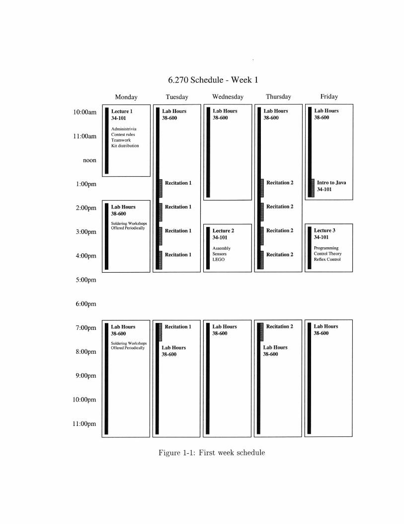
6.270 Schedule - Week 1
Monday
Lecture 134-101
AdministriviaContest rulesTeamworkKit distribution
Lab Hours38-600
Soldering WorkshopsOffered Penodically
Tuesday
10:00am
1 1:00am
noon
1:00pm
2:00pm
3:00pm
4:00pm
5:00pm
6:00pm
7:00pm
8:00pm
9:00pm
10:00pm
11:00pm
Wednesday
Lab Hours38-600
Lecture 234-101
AssemblySensorsLEGO
Lab Hours38-600
Thursday
Lab Hours38-600
Recitation 2
Recitation 2
Recitation 2
Recitation 2
IRecitation 2
Lab Hours38-600
Friday
Lab Hours38-600
Intro to Java34-101
Lecture 334-101
ProgrammingControl TheoryReflex Control
Lab Hours38-600
Figure 1-1: First week schedule
IRecitation 1
Lab Hours38-600
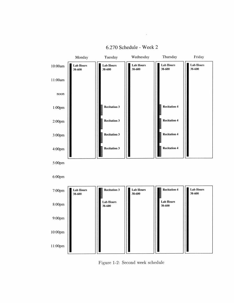
6.270 Schedule - Week 2
Wednesday
Lab Hours38-600
10:00am
11:00am
noon
1:00pm
2:00pm
3:00pm
4:00pm
5:00pm
6:00pm
7:00pm
8:00pm
9:00pm
10:00pm
11:00pm
Thursday
Lab Hours38-600
Recitation 4
Recitation 4
Recitation 4
Recitation 4
IRecitation 4
Lab Hours38-600
Figure 1-2: Second week schedule
Monday
I Lab Hours38-600
Lab Hours38-600
Tuesday
Lab Hours38-600
Recitation 3
Recitation 3
Recitation 3
Recitation 3
Recitation 3
Lab Hours38-600
Lab Hours38-600
Friday
Lab Hours38-600
Lab Hours38-600
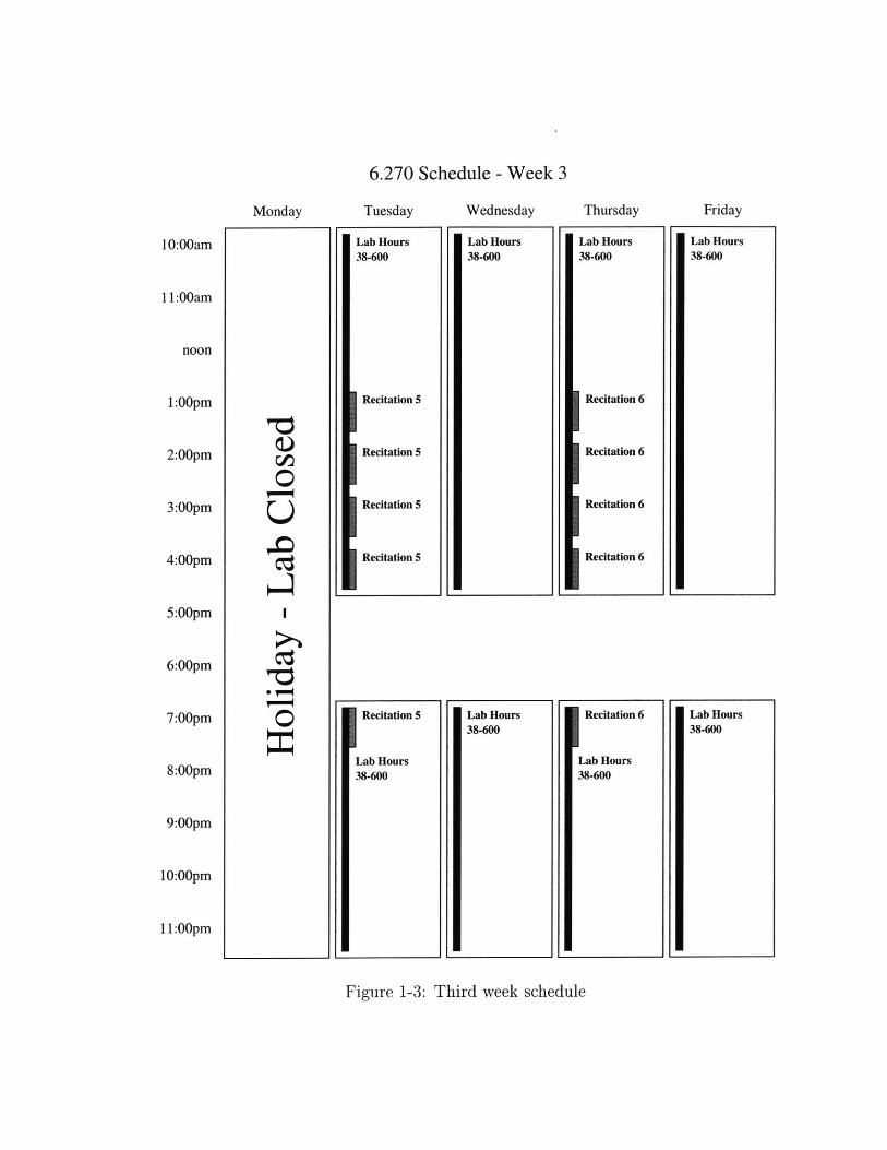
6.270 Schedule - Week 3
10:00am
11:00am
noon
1:00pm
2:00pm
3:00pm
4:00pm
5:00pm
6:00pm
7:00pm
8:00pm
9:00pm
10:00pm
11:00pm
Wednesday
Lab Hours38-600
Monday
e0
0
Figure 1-3: Third week schedule
Tuesday
Lab Hours38-600
Recitation 5
Recitation 5
Recitation 5
Recitation 5
Recitation 5
Lab Hours38-600
Lab Hours38-600
Thursday
Lab Hours38-600
Recitation 6
Recitation 6
Recitation 6
Recitation 6
Recitation 6
Lab Hours38-600
Friday
Lab Hours38-600
Lab Hours38-600
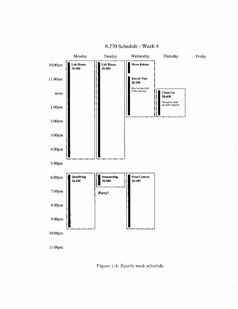
6.270 Schedule - Week 4
Wednesday
Move Robots
Round Two26-100
May be cancelledif not necessary
10:00am
11:00am
noon
1:00pm
2:00pm
3:00pm
4:00pm
5:00pm
6:00pm
7:00pm
8:00pm
9:00pm
10:00pm
11:00pm
Thursday
Clean Up38-600
One person-hourper team required
Figure 1-4: Fourth week schedule
FridayMonday
I Lab HoursS38-600
Qualifying26-100
Tuesday
Lab Hours38-600
Impounding38-600
Party!
Final Contest26-100
Chapter 2
Raiders of the Lost Parts
A deep space exploration team has uncovered what could possibly be the
remains of an ancient alien civilization on the second planet of the Eridani
system. Early missions to study the ruins have been forced to turn back by
the inhospitable conditions of the desert planet. The site is too dangerous
for humans to explore, so a robot will have to go in their place.
Your mission is to design and construct a robot which can explore the ruins
and retreive artifacts from within them. The site also appears to contain
hazardous materials which the robot will have to dispose of or avoid.
Unfortunately, you are not the only robotics team who has received word
of this discovery, so you must work quickly to be the first on the site. The
next launch window for a trip to the planet will open in three and a half
weeks, so time is very short. If you miss the window, the competition will
be the ones celebrating.
29
2.1 The Table
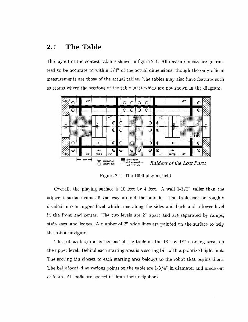
The layout of the contest table is shown in figure 2-1. All measurements are guaran-
teed to be accurate to within 1/4" of the actual dimensions, though the only official
measurements are those of the actual tables. The tables may also have features such
as seams where the sections of the table meet which are not shown in the diagram.
0000 +2
..... 0... +0.
4- ® ~ 0...............I
ng.ieba rs of Lost Parts
Figure 2-1: The 1999 playing field
Overall, the playing surface is 10 feet by 4 feet. A wall 1-1/2" taller than the
adjacent surface runs all the way around the outside. The table can be roughly
divided into an upper level which runs along the sides and back and a lower level
in the front and center. The two levels are 2" apart and are separated by ramps,
staircases, and ledges. A number of 2" wide lines are painted on the surface to help
the robot navigate.
The robots begin at either end of the table on the 18" by 18" starting areas on
the upper level. Behind each starting area is a scoring bin with a polarized light in it.
The scoring bin closest to each starting area belongs to the robot that begins there.
The balls located at various points on the table are 1-3/4" in diamater and made out
of foam. All balls are spaced 6" from their neighbors.
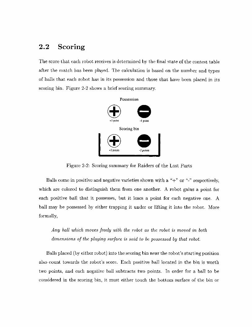
2.2 Scoring
The score that each robot receives is determined by the final state of the contest table
after the match has been played. The calculation is based on the number and types
of balls that each robot has in its possession and those that have been placed in its
scoring bin. Figure 2-2 shows a brief scoring summary.
Possession
+1 point -1 point
Scoring bin
+2 points -2 points
Figure 2-2: Scoring summary for Raiders of the Lost Parts
Balls come in positive and negative varieties shown with a "+" or "-" respectively,
which are colored to distinguish them from one another. A robot gains a point for
each positive ball that it possesses, but it loses a point for each negative one. A
ball may be possessed by either trapping it under or lifting it into the robot. More
formally,
Any ball which moves freely with the robot as the robot is moved in both
dimensions of the playing surface is said to be possessed by that robot.
Balls placed (by either robot) into the scoring bin near the robot's starting position
also count towards the robot's score. Each positive ball located in the bin is worth
two points, and each negative ball subtracts two points. In order for a ball to be
considered in the scoring bin, it must either touch the bottom surface of the bin or
another ball which is already in the bin. Balls that are both possessed and in the bin
will be counted as being only in the bin.
2.3 The Competition
The competition will be a double elimination tournament held over the course of
two days. When all but one robot has been eliminated, that robot will be crowned
champion.
* Qualifying. The first round of the contest will also serve as a qualification
round. If a robot demonstrates the ability to score points, regardless of whether
it wins or loses, it will be allowed to proceed to the next round. If it does not,
modifications may be made, and it will have two more chances in lab to run
against an inert placebo. If it cannot score points against the placebo after two
tries, it will not qualify for the rest of the contest. Losses to opponents during
this round do count towards a robot's elimination.
e Round 2. Only qualifying robots may compete in the second round. If a robot
which has lost in round one also loses in this round, it will be eliminated from
the competition. This round may be skipped if few enough robots make it past
round one.
* Final Contest. This is the main competition that everyone comes to see.
Robots will compete until all but the winner has been eliminated. At the
discretion of the Organizers, the final round of competition may be conducted
in a round-robin format, ignoring previous losses.
2.4 Rules
The following rules of play are meant to ensure a fair and interesting contest. Contes-
tants are responsible for knowing and following these rules. If you have any questions
about the legality of your robot, feel free to ask an Organizer for an official ruling
before your robot is impounded.
2.4.1 Period of Play
1. The contestants will have 60 seconds to place their robot on the playing field.
During this time, they may calibrate the robot's sensors.
2. The judges will choose a random starting orientation from four discrete direc-
tions. The robot must be placed completely within its starting area facing
in the direction chosen by the judges. Both robots will begin in symmetric
orientations.
3. When both robots are ready, the contestants must step back from the table.
Robots may not supply power to their actuators at this point. If a robot does,
it has false-started. If a robot false-starts twice, it forfeits that match and is
replaced by a placebo.
4. The beginning of the match is signaled by the judges turning on the starting
lights. The robots then have 60 seconds to try to score points.
5. During the match, the contestants must stand back from the table. Any contes-
tant who touches the machines or otherwise interferes with the match will cause
his machine to forfeit. All robots must be controlled solely by their onboard
computer.
6. At the end of 60 seconds, the robot must turn off electrical power to its actu-
ators. Software is provided to do this. Any robot that fails to do so will be
disqualified.
7. The match ends when all robots and game objects on the table come to a rest.
8. The robot that scores the most points will be the winner. In the event of a
tie, the judges will award wins to robots that have scored points, and losses to
those that have not.
2.4.2 Kits
1. All kits contain the same set of components, although some parts may be colored
differently in different kits.
2. Some parts in the kit are considered tools and may not be used on the robot.
3. Robots must be built only from the parts in the kit, except when explicitly
allowed by other rules.
4. Teams may trade only functionally identical components. This includes trading
identical LEGO parts of different colors and replacing broken components.
2.4.3 Robots
1. Robot structure must fit within a one foot cube at the start of a match; however,
they may expand once the match has begun. Only the IR broadcast beacon
and sensors may extend higher. Wires may be compressed, if necessary, to fit
this measurement.
2. All parts of a robot must be connected via LEGO. Robots may not separate or
have a tendency to break into multiple parts.
3. Decorations may be added to a robot provided they perform only an aesthetic
function, and not a structural one.
4. Robots may not intentionally damage, or attempt to damage, their opponent's
microprocessor board or infrared beacon.
5. No parts or substances may be deliberately dropped onto the playing field.
6. Any robot that appears to be a safety hazard will be disqualified from the
competition.
2.4.4 LEGO
1. Only LEGO parts may be used as robot structure.
2. A robot's structure may not be altered once the contest has begun, although
repairs may be made between rounds if time permits.
3. LEGO pieces may not be modified in any way, with the following exceptions:
* The LEGO baseplate may be modified freely.
" LEGO pieces may be modified to facilitate the mounting of sensors and
actuators.
" LEGO pieces may be modified to perform functions directly related to the
operation of a sensor. For example, holes may be drilled in a LEGO wheel
to help make an optical shaft encoder.
4. LEGO pieces may not be joined by adhesive.
5. Lubricants of any kind are not permitted.
6. One layer of rubber band or tape may be applied to LEGO wheels and treads
to alter the coefficient of friction.
2.4.5 Software
1. A robot's program may not be altered once the contest has begun, except by
specifying the transmission frequency as described below.
2. In the event of a memory failure, a new copy of the robot's program may be
downloaded between rounds. A computer will be available at the contest for
this purpose.
3. A robot may not be told its orientation or given information about its opponent.
It may only deduce this information after the match has begun.
4. Sensors may be calibrated on the table before a match begins.
2.4.6 Non-LEGO parts
1. Sensors, actuators, and other Non-LEGO parts may not be used as structural
components.
2. Non-LEGO parts may be attached to no more than five LEGO parts.
3. Non-LEGO parts may be freely modified to assist in their operation.
4. A reasonable amount of cardboard, other paper products, and tape may be used
for the purpose of creating optical shields for sensors.
5. Wire may only be used for electrical purposes and may not be dragged on the
playing surface. Wires that extend outside of the robot should be tied back.
6. The wooden dowel may be used only as a tower to mount the infrared trans-
mitter and sensors.
7. Only thin rubber bands may be used to store energy.
8. The lead-acid batteries may only be used in the standard electrical configuration
of three cells connected in series.
2.4.7 Infrared Beacon and Light Sources
1. All entries must carry a beacon that is capable of broadcasting infrared (IR)
light modulated at either 100 Hertz or 125 Hertz with a 40,000 Hertz carrier.
Hardware and software is provided to do this. This beacon allows robots to
locate each other on the playing field.
2. Robots failing to meet the IR transmission specification, or in any way modify-
ing or jamming their transmission during the round of play will be disqualified.
3. Judges will assign frequencies for IR emitters to the robots at the beginning of
each match. The robot must transmit this frequency for the duration of the
match. Software is provided to do this.
4. The beacon must be located at between 17 and 18 inches above the surface
of the playing field when mounted on the robot. The position of the beacon
relative to the microprocessor board may not change during the round.
5. The beacon may not be intentionally obstructed. Because of this, robots may
not extend above 16 inches or lift objects above this height.
6. A bright polarized lamp will be placed behind each end of the table. The lamp
near the robot transmitting 100 Hertz IR will have a +45 degree polarization,
while the lamp near the robot transmitting 125 Hertz IR will have a -45 degree
polarization.
2.4.8 Placebos
1. In matches involving only one robot player, a placebo will stand in for the other.
2. The placebo will not intentionally move from its starting area or attempt to
score points.
3. The placebo will conform to all rules concerning the transmission of the IR
beacon.
2.5 Extra Electronics
2.5.1 The Sensor Store
In order to encourage variety in robot designs, each team will be given a sample
set of sensors and an allowance of "play money" with which they may purchase
additional sensors from the Organizers. No refunds will be permitted, so contestants
are encouraged to experiment with the sample sensors before making decisions on
which sensors to buy. Note that sensors purchased from the sensor store are considered
kit parts and must be used in accordance with all applicable rules.
2.5.2 $20 Electronics Rule
A team may spend up to $20 of its own funds to purchase electronic components from
non-6.270 sources. Contestants are encouraged to use this rule to explore new ways
of sensing or otherwise make their robot more interesting. Teams taking advantage
of this provision, however, must abide by the following guidelines:
1. Batteries, motor driver circuitry, and microprocessors of any kind may not be
used. Motor driver circuitry includes motor driver chips, relays, and power
transistors.
2. Resistors rated less than 1 watt and capacitors valued less than 100 pF may be
used freely, without counting towards the $20 total.
3. Contestants who add any non-kit parts to their robot must turn in a design
report which includes a description of the modification, a schematic of all added
circuitry, and store receipts for the parts purchased. This design report must be
turned in with the robot at impounding. Any robot found with added circuitry
that has not be documented in this fashion will be disqualified.
4. If a contestant wishes to use parts obtained through means other than retail
purchase, an equivalent cost will be assigned by the Organizers. This estimate
must be obtained in writing from the Organizers and be included in the design
report described above.
Chapter 3
The Human Factor
Participating in a challenging activity can be either a rewarding or stressful experi-
ence. Whether it is the former or the latter, however, depends entirely on you. In
6.270, you will be faced with the challenge of building a functional robot in a short
period of time, which is by no means an easy task. Accomplishing this will not only
require technical expertise, but also the ability to motivate yourself and to contribute
as a member of a team.
Since each person is different and has his own unique set of skills to offer, there
is no one correct way to approach the course. This chapter, therefore, is meant to
present some suggestions for dealing with the human aspects of the course. Whether
you take this advice or develop your own approach is entirely up to you.
3.1 Survival Tips
When working on a large project, many human factors come into play. In order to
effectively contribute, you must not only have the knowledge, but also the desire
and ability to apply it. Remaining motivated for the duration of the task can be
40
difficult, and participants often find themselves feeling burnt out and stressed. This
stress results in fatigue, irritability, and poor performance which in turn leads to more
problems and more stress. If you keep the following tips in mind, however, you will
be able to minimize your stress and stay motivated:
" Have fun. The best way to remain motivated is to simply enjoy the experience
and have fun. Beware of falling into the trap of thinking that your robot has
to be the best. This course is not about winning or scoring a lot of points; It is
about having fun and learning something in the process. If you simply keep a
positive attitude and take the time to enjoy the course, you will find it to be a
very rewarding experience.
" Take care of yourself. While skipping a few meals or pulling an all-nighter
might seem like a good way to get some extra work done, in the long run, it
tends to be counterproductive. Neglecting your body's needs will inevitably
leave you tired and drained, making you much less productive and increasing
your chances of catching an illness. If you eat and sleep on a regular schedule,
you will find that you are healtier and more motivated.
" Start early. Building a robot takes longer than you expect, even when you take
that fact into account. By starting early and following a reasonable schedule,
you will allow yourself the time to get things done without the stress of working
at the last minute. If you plan well, you can spend the last few days goofing
around with your robot and making those little last minute adjustments instead
of pulling all-nighters just trying to make the robot work.
" Share your ideas. Many people think that by keeping the design of their
robot a secret they will gain a competitive advantage; however, this is usually
not the case. When you are willing to share your ideas with others, others will
be willing to share their ideas with you. Quite often, another team will be able
to suggest an idea that you have missed or a solution that you have been unable
to find.
* Take a break. If you find yourself arguing with your teammates or becoming
frustrated over a problem, take a break and do something else. Getting away
from the robot and your teammates for awhile will help you relax and allow you
to collect your thoughts. The world has many experiences to offer and exploring
some of them might be just what you need.
3.2 Teamwork
One of the most essential parts of any large project is teamwork. A person working
alone will not have the time to learn and do everything necesssary to accomplish the
task. A team, on the other hand, can draw upon the talents and manpower of all of
its members, making it much more productive than an individual.
3.2.1 Planning
Before a team begins work on a problem, it has to develop a plan. Rushing ahead is
likely to cause work to be duplicated or important tasks to be missed. Worse still,
failure to plan ahead can lead to incompatibilities in parts that are supposed to fit
together. When discovered too late, these errors can prove fatal to the project.
A good place to begin planning is to decide what the team is interested in accom-
plishing. Some teams are focused on winning while others just want to have a little
fun. Still others are interested in the learning process and would prefer to spend more
time on the parts that are most educational. It does not matter what goals a team
sets for itself as long as all the members understand and agree with the overall vision.
This will help coordinate the efforts of all the team members and provide direction
for the project.
3.2.2 Brainstorming
Teams often employ the technique of brainstorming for generating potential solutions
to a problem. During such a session, participants think alound, suggesting ideas as
quickly as they can think of them. Other members of the team can then use those
thoughts to create new ideas of their own which they throw back to the group. When
it works well, a team can combine the knowledge and creativity of all its members
to generate solutions that an individual would not even consider. The following
guidelines will help make a brainstorming session as effective as possible:
1. No squashing. Negative comments have no place in brainstorming. Insulting
another person's ideas will cause them to be reluctant to offer further sugges-
tions.
2. Don't hold back. The process only works if everyone shares their thoughts.
Even the silliest idea can often inspire a great one.
3. Stay on topic. During the course of discussion, it is easy to wander off on a
tangent. Focus on the problem at hand and avoid distractions.
4. Relax. Ideas flow more freely in a relaxed environment. Find a quiet, comfort-
able place where the team can concentrate on the task at hand.
3.2.3 Constructive Conflict
Teams composed of members who always agree with each other work quickly and
efficiently but never produce the best solution. Instead, the teammates who disagree
often are the ones that build the strongest teams. This may seem counterintuitive
at first, but it turns out that conflict, if handled correctly, can be one of a team's
greatest strengths.
Shouting at each other and throwing tantrums will certainly not accomplish any-
thing, but calm, rational debate allows the team to view a topic from multiple per-
spectives. This not only allows the team to consider various possible solutions, but
it also forces the issue to be examined in greater depth. Often, you will find that an
idea that seems good at first will not hold up under the scrutiny of another team-
mate. Disagreements between teammates force the team to constantly reevaluate and
improve the design and may even help generate new ideas.
In order to engage in rational debate, you must walk the fine line between strongly
defending your position and being open-minded enough to consider other ideas. De-
bate is not about being right or winning the argument; It is about examining both
sides of an issue, so that the team can choose the best course of action. It is very
easy, during an intense debate, to forget that you are supposed to be participating in
a productive task, so it is helpful to keep the following guidelines in mind:
1. Prepare a strong position and present it forcefully, but keep an open mind.
2. Allow others a chance to speak and listen attentively while they do.
3. Try to view the problem from multiple viewpoints, including the opposing one.
4. Do not take disagreement and rejection personally.
3.2.4 Friends and Enemies
Forming good relationships with your teammates is one of the primary lessons of
6.270. In past years, the ability to work well together has often been the most
critical factor in a team's success or failure. Participants whose robots do not perform
well often attribute their failure to poor team dynamics and arguments between
teammates. Contest winners, on the other hand, usually attribute their success to
their enjoyment of the course and the fun they had working together with their friends.
The relationships you form with your teammates are likely to continue long after
the course is over. In the past, teams formed by complete strangers have left as very
good friends, and unfortunately, good friends have left the course no longer speaking
with one another. Remember that your teammates are human, and your actions
affect not only the project, but also the people you are working with. Putting in the
extra effort to work well with your teammates will pay off both in the contest and for
a long time afterwards.
3.3 Implementation
Building a robot is usually more work than an individual can handle on his own, so
it is necessary to work as part of a team. Everyone should help out by providing part
of the labor necessary to design and implement the robot, but in order to do this, the
work needs to be divided up in some fashion.
3.3.1 Division of Labor
Each person brings a different set of strengths to the team, so many teams opt to
divide the work into a number of subtasks, each of which becomes the responsibility
of an individual team member. In this specialist approach, each person works on one
area of the project and becomes an expert at it. The most common division in 6.270
is into hardware, software, and LEGO construction, but as long as the work is divided
along clearly defined abstraction barriers, the communication needed to organize the
team is small. This tends to be very efficient, especially for teams whose members
come into the course with varying backgrounds and interests, though it tends to lead
to a very narrow learning experience for the individual.
Another popular division of labor is the generalist approach, where every member
of the team shares equally in all aspects of the implementation. This allows each indi-
vidual to have a say in every part of the design and to gain an overall understanding
of the process. It also requires that the teammates work in close proximity which can
lead to a more fun and relaxed experience. Because of the amount of coordination
needed between teammates, though, a great deal of time will have to be spent on
organization and communication. This makes the implemenation less efficient, but
can often lead to a better learning experience.
3.3.2 Debugging
Debugging can be a long and tedious process, so it is important to follow good design
practice to minimize the number of bugs you will have to fix. Regardless of how
careful you are, though, mistakes are inevitable and debugging will be necessary. As
a general rule, it will take longer than you think to debug, so it is always better to
allocate too much time for debugging than too little.
Occasionally, you will run into a bug that just seems to elude you. In these cases,
instead of banging your head on the wall, you should . Have a teammate review your
work and search for the bug. It may be that you are using a bad assumption or that
you are continually missing the same mistake. When this happens, a teammate can
bring a fresh perspective to the problem which might yield the answer.
Some teams take this debugging philosophy even further. No person on the team
ever debugs his own work. Instead, each person gives their work to another teammate
and that person debug its. This way, each part of the project benefits from the input
of at least two people.
3.4 Contest Tips
Everything always goes wrong at the worst possible time, which in 6.270, is contest
night. There is nothing more heartbreaking than having your robot not work be-
cause of some small oversight. To help minimize the chances of such unfortunate
occurrences, follow the tips below when preparing for the competition:
1. When making practice runs with your robot, try to avoid helping it. During
actual competition, you will not be able to touch your robot when it does
something wrong.
2. Practice your calibration routine in lab, so you can do it quickly and accurately
at the contest. You must be able to complete your routine within a fixed time
limit.
3. The lighting conditions at the contest will be different from those in the lab.
Make sure that your light sensors are well-shielded and can be calibrated to
work under different conditions.
4. Be aware of how your proximity will affect the calibration of your robot. When
you lean over your robot, you can cast shadows or cause reflections which could
affect the measurements of your sensors.
5. Develop a checklist for preparing your robot to compete. Between rounds you
should examine your robot and repair anything that has broken.
6. Bring a repair kit to the contest. This should include a fresh set of batteries and
a replacement for any part that tends to wear down or break during operation.
7. Have fun.
Chapter 4
Electronic Assembly
This chapter presents an introduction to electronic assembly followed by step-by-step
instructions for assembling the hardware used in 6.270. The instructions assume no
prior background in electronics and should provide enough information to get you
started. It is recommended that you assemble the components in the order presented
by this chapter. The sections are arranged to give you a gentle introduction before
you go on to tackle the tougher tasks.
If ever there was a place in life where neatness counts, it is in electronic assembly.
A neatly built and carefully soldered circuit will peform well for years. A sloppily
and hastily assembled circuit, however, will cause ongoing problems and failures at
inopportune times. It is well worth the extra effort to make sure you get it right the
first time.
4.1 Soldering
Soldering is a method of creating electrically conductive connections between elec-
tronic components. A special type of metal, called solder, is melted onto the joint
48
and allowed to harden. This forms a bond between the components which joins them
both structurally and electrically. A soldering iron is extremely valuable for con-
structing electronic circuits, but as with any tool, you must begin by mastering the
skills necessary to use it.
4.1.1 Safety
Soldering is not a dangerous activity, but if you do not respect the soldering iron,
it can does have the potential to cause harm. While you work, it is important to
observe the following safety rules:
1. Keep the soldering iron tip away from everything except the point to be soldered.
The iron is hot and can easily damage parts, cause burns, or even start a fire.
2. Keep the soldering iron in its holder when not in use. Never wave the soldering
iron around or hand it to another person. If someone else wants the iron, place
it in its stand and let him pick it up from there.
3. Never assume that a soldering iron is cold. Always check the iron before you
pick it up.
4. Do not touch a joint immediately after soldering it. It takes a moment for the
solder to cool back down.
4.1.2 Technique
Before you begin any work with the soldering iron, you should assemble all of the
tools that you will be using. The ones that you will require include a soldering iron,
stand, solder, and a damp sponge. You may also wish to have a set of helping hands,
cutters, and wire strippers available if needed for the task.
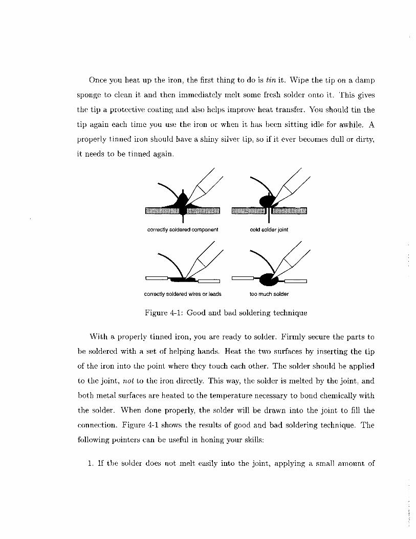
Once you heat up the iron, the first thing to do is tin it. Wipe the tip on a damp
sponge to clean it and then immediately melt some fresh solder onto it. This gives
the tip a protective coating and also helps improve heat transfer. You should tin the
tip again each time you use the iron or when it has been sitting idle for awhile. A
properly tinned iron should have a shiny silver tip, so if it ever becomes dull or dirty,
it needs to be tinned again.
. !II I ||
correctly soldered component cold solder joint
correctly soldered wires or leads too much solder
Figure 4-1: Good and bad soldering technique
With a properly tinned iron, you are ready to solder. Firmly secure the parts to
be soldered with a set of helping hands. Heat the two surfaces by inserting the tip
of the iron into the point where they touch each other. The solder should be applied
to the joint, not to the iron directly. This way, the solder is melted by the joint, and
both metal surfaces are heated to the temperature necessary to bond chemically with
the solder. When done properly, the solder will be drawn into the joint to fill the
connection. Figure 4-1 shows the results of good and bad soldering technique. The
following pointers can be useful in honing your skills:
1. If the solder does not melt easily into the joint, applying a small amount of
extra solder to the iron will improve heat transfer.
2. If a ball of solder begins to collect on the tip of the iron, use a damp sponge to
wipe it off.
3. Do not hold the iron against the joint for more than about 8 seconds. Many
electronic components can be damaged by excessive amounts of heat.
4. When working with stranded wire, it helps to tin the end of the wire. This
holds the strands together and improves heat transfer. Apply heat with the
soldering iron and let the solder flow between the stands.
5. When attaching wires, remove as little insulation as possible to make the joint.
Exposing too much wire is likely to cause short circuits.
6. Never use the iron to melt anything but solder. Impurities will damage the iron
and cause it to smoke. If the tip becomes dirty, it can be cleaned by melting
generous amounts of solder onto it.
A cold solder joint occurs when an air bubble or other impurity has entered the
joint during cooling. This is most commonly caused by an attempt to paint the solder
onto a joint by applying it to the soldering iron directly. The solder does not flow
properly into the joint, causing the it to ball up and have a dull appearance. These
joints are brittle and make poor electrical connection. To fix such a joint, heat it
with the soldering iron until it melts into the joint properly. If the cold solder joint
reappears, remove the solder and then try again.
4.1.3 Mounting Components
When mounting components on a circuit board, the general rule is to try to mount
them as close to the board as possible. The primary exceptions to this rule are
components that must be bent or folded over before being soldered. Resistors and
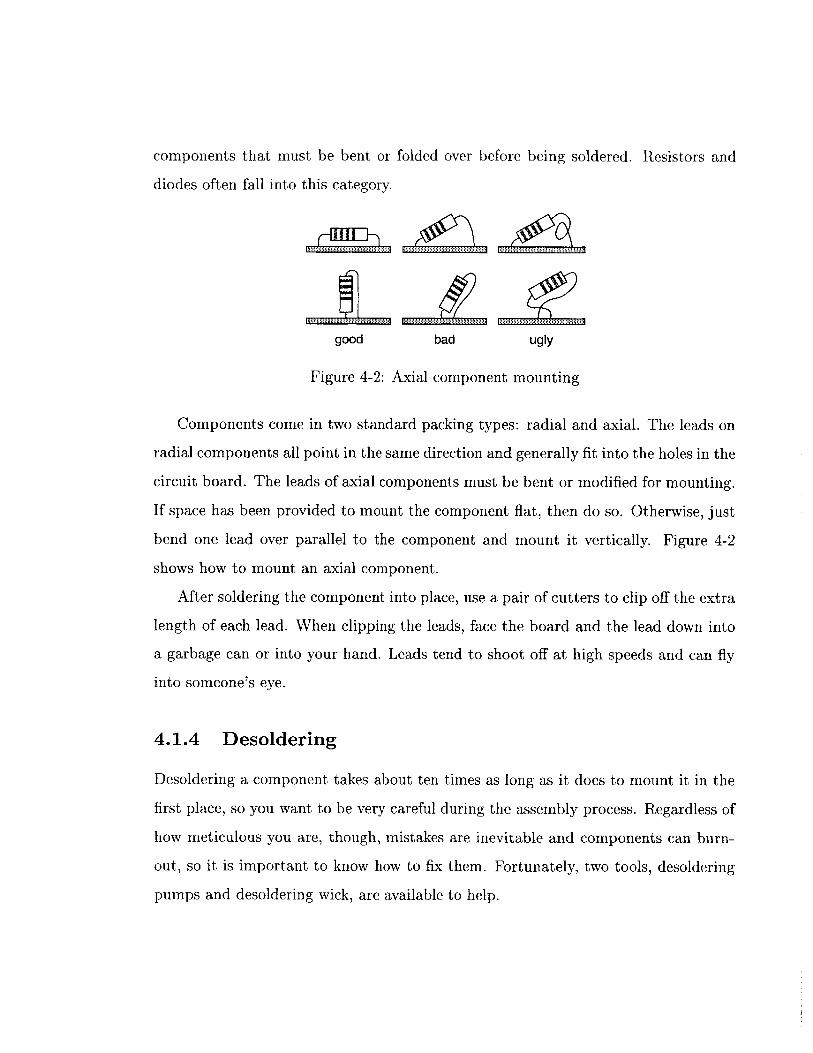
diodes often fall into this category.
good bad ugly
Figure 4-2: Axial component mounting
Components come in two standard packing types: radial and axial. The leads on
radial components all point in the same direction and generally fit into the holes in the
circuit board. The leads of axial components must be bent or modified for mounting.
If space has been provided to mount the component flat, then do so. Otherwise, just
bend one lead over parallel to the component and mount it vertically. Figure 4-2
shows how to mount an axial component.
After soldering the component into place, use a pair of cutters to clip off the extra
length of each lead. When clipping the leads, face the board and the lead down into
a garbage can or into your hand. Leads tend to shoot off at high speeds and can fly
into someone's eye.
4.1.4 Desoldering
Desoldering a component takes about ten times as long as it does to mount it in the
first place, so you want to be very careful during the assembly process. Regardless of
how meticulous you are, though, mistakes are inevitable and components can burn-
out, so it is important to know how to fix them. Fortunately, two tools, desoldering
pumps and desoldering wick, are available to help.
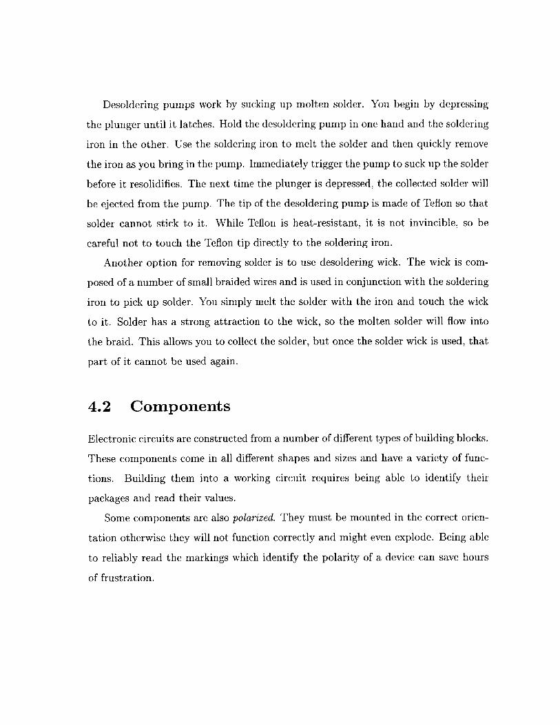
Desoldering pumps work by sucking up molten solder. You begin by depressing
the plunger until it latches. Hold the desoldering pump in one hand and the soldering
iron in the other. Use the soldering iron to melt the solder and then quickly remove
the iron as you bring in the pump. Immediately trigger the pump to suck up the solder
before it resolidifies. The next time the plunger is depressed, the collected solder will
be ejected from the pump. The tip of the desoldering pump is made of Teflon so that
solder cannot stick to it. While Teflon is heat-resistant, it is not invincible, so be
careful not to touch the Teflon tip directly to the soldering iron.
Another option for removing solder is to use desoldering wick. The wick is com-
posed of a number of small braided wires and is used in conjunction with the soldering
iron to pick up solder. You simply melt the solder with the iron and touch the wick
to it. Solder has a strong attraction to the wick, so the molten solder will flow into
the braid. This allows you to collect the solder, but once the solder wick is used, that
part of it cannot be used again.
4.2 Components
Electronic circuits are constructed from a number of different types of building blocks.
These components come in all different shapes and sizes and have a variety of func-
tions. Building them into a working circuit requires being able to identify their
packages and read their values.
Some components are also polarized. They must be mounted in the correct orien-
tation otherwise they will not function correctly and might even explode. Being able
to reliably read the markings which identify the polarity of a device can save hours
of frustration.
4.2.1 Resistors
Resistors are usually small cylindrical devices with color-coded bands indicating their
value. Most of the resistors that you will use are 1/8 watt, which is a very low power
rating, thus they are rather tiny devices. Resistors with higher power ratings tend to
be much larger. A 2 watt resistor is a large cylinder, while a 5 watt resistor has a
large rectangular package. Regardless of size, all resistors are nonpolarized, so they
may be installed in either direction without causing problems.
The largest resistors often have their value printed on them, but all other resistors
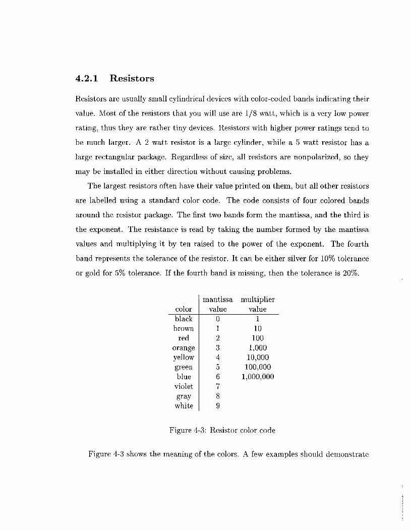
are labelled using a standard color code. The code consists of four colored bands
around the resistor package. The first two bands form the mantissa, and the third is
the exponent. The resistance is read by taking the number formed by the mantissa
values and multiplying it by ten raised to the power of the exponent. The fourth
band represents the tolerance of the resistor. It can be either silver for 10% tolerance
or gold for 5% tolerance. If the fourth band is missing, then the tolerance is 20%.
mantissa multipliercolor value valueblack 0 1brown 1 10
red 2 100orange 3 1,000yellow 4 10,000green 5 100,000blue 6 1,000,000
violet 7gray 8
white 9
Figure 4-3: Resistor color code
Figure 4-3 shows the meaning of the colors. A few examples should demonstrate
how to read a resistor:
* brown, black, red: 1,OOOQ or 1kQ
* yellow, violet, orange: 47,OOO or 47kQ
* red, red, yellow: 220,OOOQ or 220kQ
4.2.2 Resistor Packs
Isolated Element Common Terminal
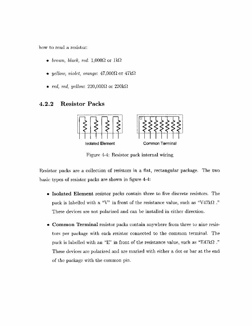
Figure 4-4: Resistor pack internal wiring
Resistor packs are a collection of resistors in a flat, rectangular package. The two
basic types of resistor packs are shown in figure 4-4:
* Isolated Element resistor packs contain three to five discrete resistors. The
pack is labelled with a "V" in front of the resistance value, such as "V47kQ ."
These devices are not polarized and can be installed in either direction.
* Common Terminal resistor packs contain anywhere from three to nine resis-
tors per package with each resistor connected to the common terminal. The
pack is labelled with an "E" in front of the resistance value, such as "E47kQ ."
These devices are polarized and are marked with either a dot or bar at the end
of the package with the common pin.
4.2.3 Capacitors
Capacitors are available in a variety of types and values:
" Monolithic capacitors are small components about the size and shape of the
head of a match. They are excellent choices when small values (1.0pF or less)
are needed because they are compact and inexpensive. They are never polarized.
* Electrolytic capacitors look like minature tin cans with a plastic wrapper.
They are available in large values (1.OpF or greater), but become quite bulky
as the value increases. They are fairly inexpensive, so they are a common choice
for many applications. Except for a few special cases, electrolytics are usually
polarized.
" Tantalum capacitors are compact, bulb-shaped components. They are excel-
lent for larger values (1.0pF or greater), since they are smaller and more reliable
than electrolytic. Unfortunately, though, they are also much more expensive.
They are always polarized.
Polarized capacitors have a tendency to explode when they are mounted back-
wards, so it is important to know how to read them correctly. Some of them are
easy and have one or both of the leads marked with a plus (+) or minus (-). Others
have the positive lead marked with either a dot or a vertical bar. This should not be
confused with the stripe with several minus signs on it which marks the negative lead
on some electrolytics.
Reading capacitor values can be even more confusing than determining their po-
larity. Capacitors often have numbers printed on the package which have nothing to
do with the value, so the first task is to figure out which are the relevant numbers.
For large capacitors (1.0pF or greater), the value is often printed plainly on the
packages, such as "4.7pF ." In some cases, the "p" symbol acts as a decimal point
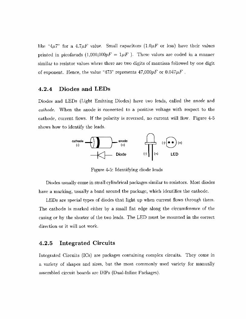
like "4p7" for a 4.7pF value. Small capacitors (1.0p-F or less) have their values
printed in picofarads (1,000,000pF = 1pF ). These values are coded in a manner
similar to resistor values where there are two digits of mantissa followed by one digit
of exponent. Hence, the value "473" represents 47,OOOpF or 0.047pF .
4.2.4 Diodes and LEDs
Diodes and LEDs (Light Emitting Diodes) have two leads, called the anode and
cathode. When the anode is connected to a positive voltage with respect to the
cathode, current flows. If the polarity is reversed, no current will flow. Figure 4-5
shows how to identify the leads.
cathode anode 0 0e)
Diode (+) LED
Figure 4-5: Identifying diode leads
Diodes usually come in small cylindrical packages similar to resistors. Most diodes
have a marking, usually a band around the package, which identifies the cathode.
LEDs are special types of diodes that light up when current flows through them.
The cathode is marked either by a small flat edge along the circumference of the
casing or by the shorter of the two leads. The LED must be mounted in the correct
direction or it will not work.
4.2.5 Integrated Circuits
Integrated Circuits (ICs) are packages containing complex circuits. They come in
a variety of shapes and sizes, but the most commonly used variety for manually
assembled circuit boards are DIPs (Dual-Inline Packages).
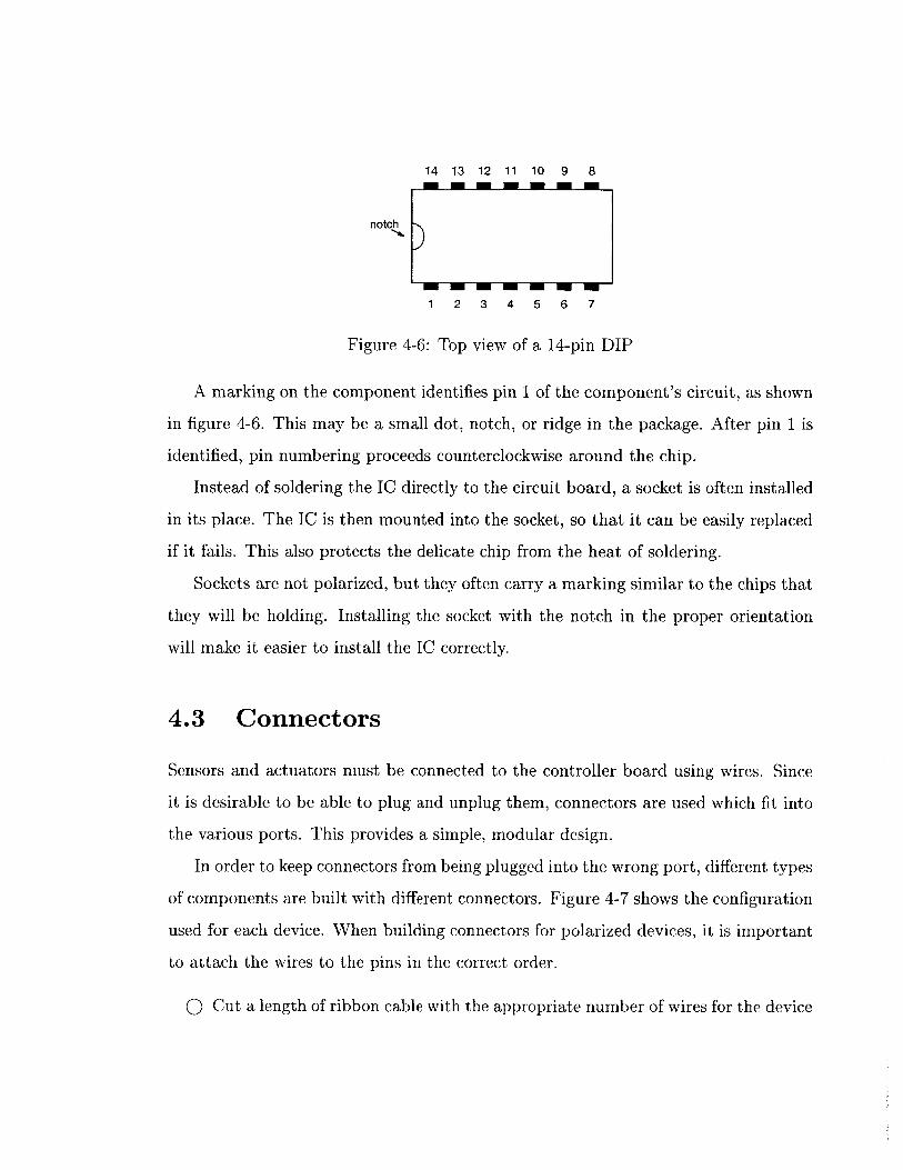
14 13 12 11 10 9 8
notch
1 2 3 4 5 6 7
Figure 4-6: Top view of a 14-pin DIP
A marking on the component identifies pin 1 of the component's circuit, as shown
in figure 4-6. This may be a small dot, notch, or ridge in the package. After pin 1 is
identified, pin numbering proceeds counterclockwise around the chip.
Instead of soldering the IC directly to the circuit board, a socket is often installed
in its place. The IC is then mounted into the socket, so that it can be easily replaced
if it fails. This also protects the delicate chip from the heat of soldering.
Sockets are not polarized, but they often carry a marking similar to the chips that
they will be holding. Installing the socket with the notch in the proper orientation
will make it easier to install the IC correctly.
4.3 Connectors
Sensors and actuators must be connected to the controller board using wires. Since
it is desirable to be able to plug and unplug them, connectors are used which fit into
the various ports. This provides a simple, modular design.
In order to keep connectors from being plugged into the wrong port, different types
of components are built with different connectors. Figure 4-7 shows the configuration
used for each device. When building connectors for polarized devices, it is important
to attach the wires to the pins in the correct order.
0 Cut a length of ribbon cable with the appropriate number of wires for the device
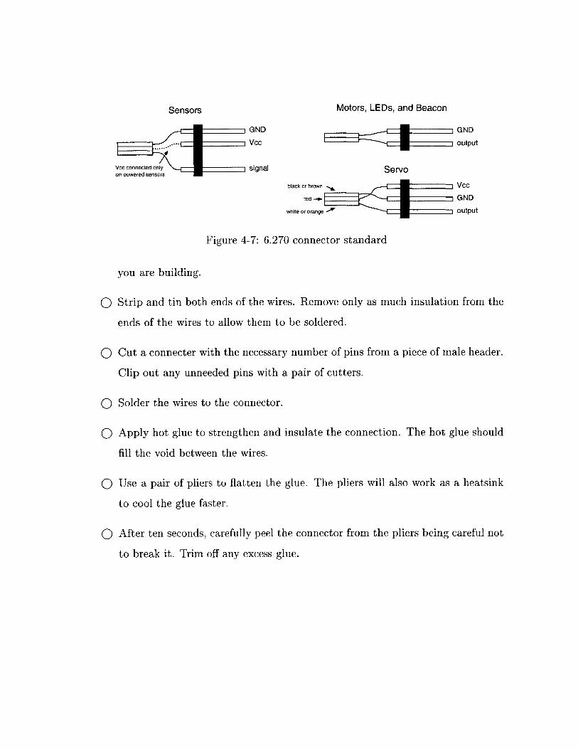
Motors, LEDs, and Beacon
GND
Vcc
signal
GND
output
Servo
black or brown Vcc
red -+ GND
white or orange output
Figure 4-7: 6.270 connector standard
you are building.
o Strip and tin both ends of the wires. Remove only as much insulation from the
ends of the wires to allow them to be soldered.
o Cut a connecter with the necessary number of pins from a piece of male header.
Clip out any unneeded pins with a pair of cutters.
o Solder the wires to the connector.
o Apply hot glue to strengthen and insulate the connection. The hot glue should
fill the void between the wires.
o Use a pair of pliers to flatten the glue. The pliers will also work as a heatsink
to cool the glue faster.
o After ten seconds, carefully peel the connector from the pliers being careful not
to break it. Trim off any excess glue.
Sensors
4.4 Motors
The DC motors used in 6.270 are great for building robots because they are compact
and powerful. Unfortunately, though they are not designed to be used with LEGO
parts. To make them compatible with your robot, you will have to legoize them.
i-E Mount a LEGO gear on the motor shaft
o If the motor comes with a metal gear on its shaft, remove it with a pair of
wire strippers. Place the jaws of the strippers between the motor and gear
and squeeze. When the strippers close, the bevel in the cutters should pry
the gear off.
o Shrink a piece of -1-" heat-shrink tubing onto the motor's shaft. Then16
shrink two additional j" pieces around that. An 8-tooth LEGO gear should
now fit snugly over the tubing.
o Push an 8-tooth gear over the head-shrink tubing. Make sure that it goes
all the way on and that it is aligned correctly.
o Cut off any excess tubing which sticks out from the end of the gear. Place
a drop of hot glue on the end of the gear to add extra support.
2-E Legoize the motor
o Construct the jig shown in figure 4-8 without the topmost 4x8 LEGO plate.
This will be necessary to align the pieces as they are assembled.
o Cut off the nubs from a 2x4 LEGO plate. Attach a piece of double-sided
foam tape to the top of it. This will become the bottom of the legoized
motor. Mount this into the bottom of the jig.
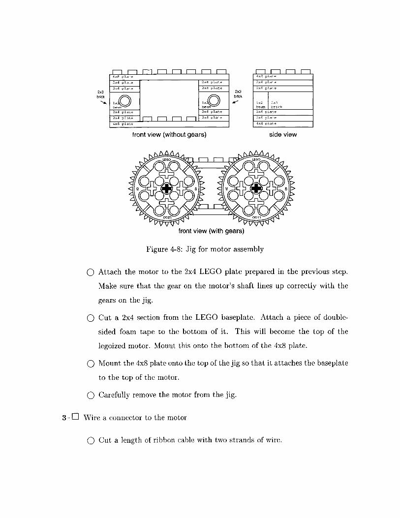
2x3brick
4x8 plate
2x4 plate 2x4 plate
2x4 plate 2x4 plate
lx 1x0
bea0m bea
2x4 plate 2x4 plate2x4
plate [] W ] r] 2x4 plate
4x8 plate
front view (without gears)
2x3brick
side view
front view (with gears)
Figure 4-8: Jig for motor assembly
o Attach the motor to the 2x4 LEGO plate prepared in the previous step.
Make sure that the gear on the motor's shaft lines up correctly with the
gears on the jig.
o Cut a 2x4 section from the LEGO baseplate. Attach a piece of double-
sided foam tape to the bottom of it. This will become the top of the
legoized motor. Mount this onto the bottom of the 4x8 plate.
o Mount the 4x8 plate onto the top of the jig so that it attaches the baseplate
to the top of the motor.
o Carefully remove the motor from the jig.
3-E Wire a connector to the motor
O Cut a length of ribbon cable with two strands of wire.
o On the side of the motor are two metal leads or pads. Solder one wire to
each.
o Solder the other end of the wire to a connector appropriate for a motor.
o Glue the wire to the case of the motor using hot glue. This will provide
stress relief to protect the solder joints.
4.5 Servo
A servo is an electric motor with an internal gear train, position sensor, and driver
circuitry which allows the motor to be positioned with reasonable precision based
upon the input signal. It can be moved to any orientation in an approximately 180
degree range. Before the servo can be used with the controller board, though, its
connector must be replaced.
o Cut the servo's connector off.
o Strip and tin the ends of the wires.
o Solder on the new connector. The servo is polarized, so it is important to
reconnect the wires correctly. The control wire is either white or orange, the
power (Vcc) wire is always red, and the ground wire is either black or brown.
Chapter 5
Sensors
The concept of a sensor should already be familiar to you. You have an array of
sensors which you use to feel, see, hear, taste, and smell. You rely on these senses for
just about everything you do. Without them, you would be incapable of performing
even the most simple tasks.
Robots are no different. Without sensors, they are merely machines, incapable of
adapting to any change in the environment. Sensors give your robot the ability to
collect information about the world around it and to choose an action appropriate to
the situation.
After reading this chapter, you should take some time to play with your sensors.
Wire at least one of each type and learn how it works, what values it returns, and
under what conditions it will production those values. Every sensor has its own little
quirks, and only through experimentation will you acquire the expertise necessary to
integrate them into your robot.
63
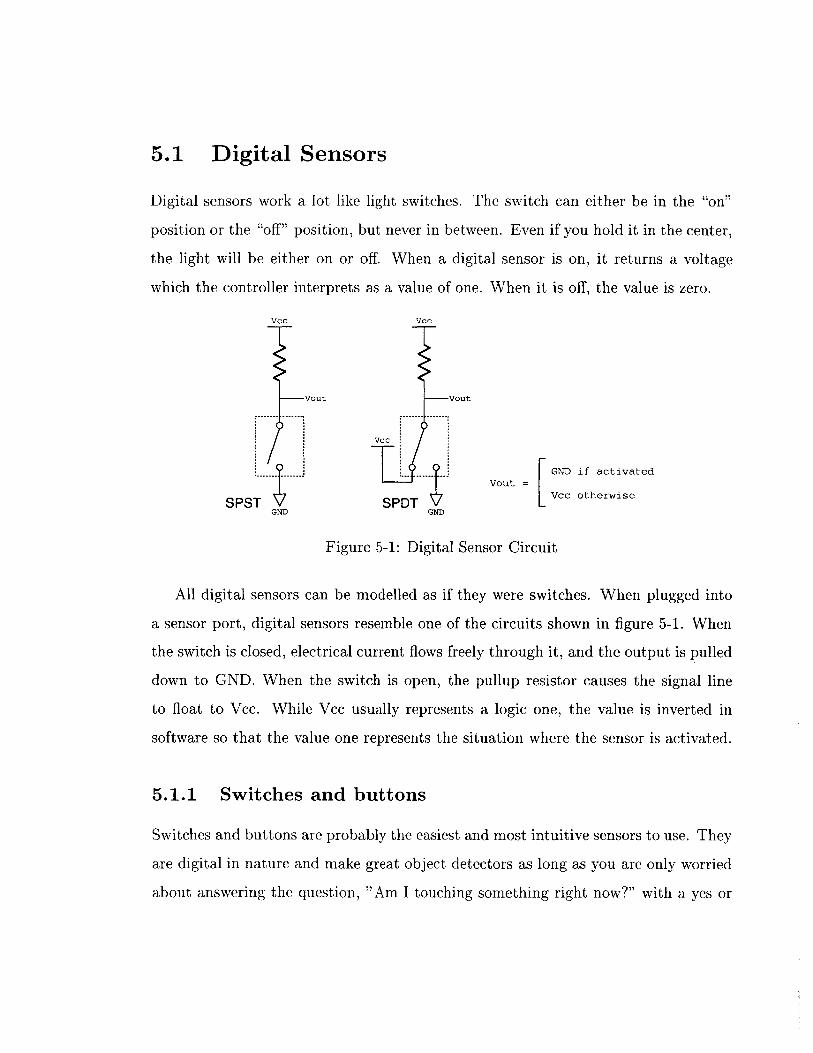
5.1 Digital Sensors
Digital sensors work a lot like light switches. The switch can either be in the "on"
position or the "off" position, but never in between. Even if you hold it in the center,
the light will be either on or off. When a digital sensor is on, it returns a voltage
which the controller interprets as a value of one. When it is off, the value is zero.
Vcc Vcc
Vout -Vout
VCC
L.GND if activated
GND GND
Figure 5-1: Digital Sensor Circuit
All digital sensors can be modelled as if they were switches. When plugged into
a sensor port, digital sensors resemble one of the circuits shown in figure 5-1. When
the switch is closed, electrical current flows freely through it, and the output is pulled
down to GND. When the switch is open, the pullup resistor causes the signal line
to float to Vcc. While Vcc usually represents a logic one, the value is inverted in
software so that the value one represents the situation where the sensor is activated.
5.1.1 Switches and buttons
Switches and buttons are probably the easiest and most intuitive sensors to use. They
are digital in nature and make great object detectors as long as you are only worried
about answering the question, "Am I touching something right now?" with a yes or
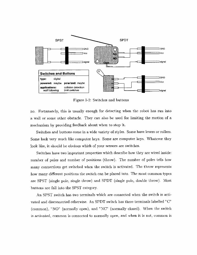
SPST SPDT
GND GND
signal R1signal
Switches and Buttons
type: digital
powered: maybe polarized: maybe VC
applications: collision detectionwall following limit switchessignal
Figure 5-2: Switches and buttons
no. Fortunately, this is usually enough for detecting when the robot has run into
a wall or some other obstacle. They can also be used for limiting the motion of a
mechanism by providing feedback about when to stop it.
Switches and buttons come in a wide variety of styles. Some have levers or rollers.
Some look very much like computer keys. Some are computer keys. Whatever they
look like, it should be obvious which of your sensors are switches.
Switches have two important properties which describe how they are wired inside:
number of poles and number of positions (throw). The number of poles tells how
many connections get switched when the switch is activated. The throw represents
how many different positions the switch can be placed into. The most common types
are SPST (single pole, single throw) and SPDT (single pole, double throw). Most
buttons are fall into the SPST category.
An SPST switch has two terminals which are connected when the switch is acti-
vated and disconnected otherwise. An SPDT switch has three terminals labelled "C"
(common), "NO" (normally open), and "NC" (normally closed). When the switch
is activated, common is connected to normally open, and when it is not, common is
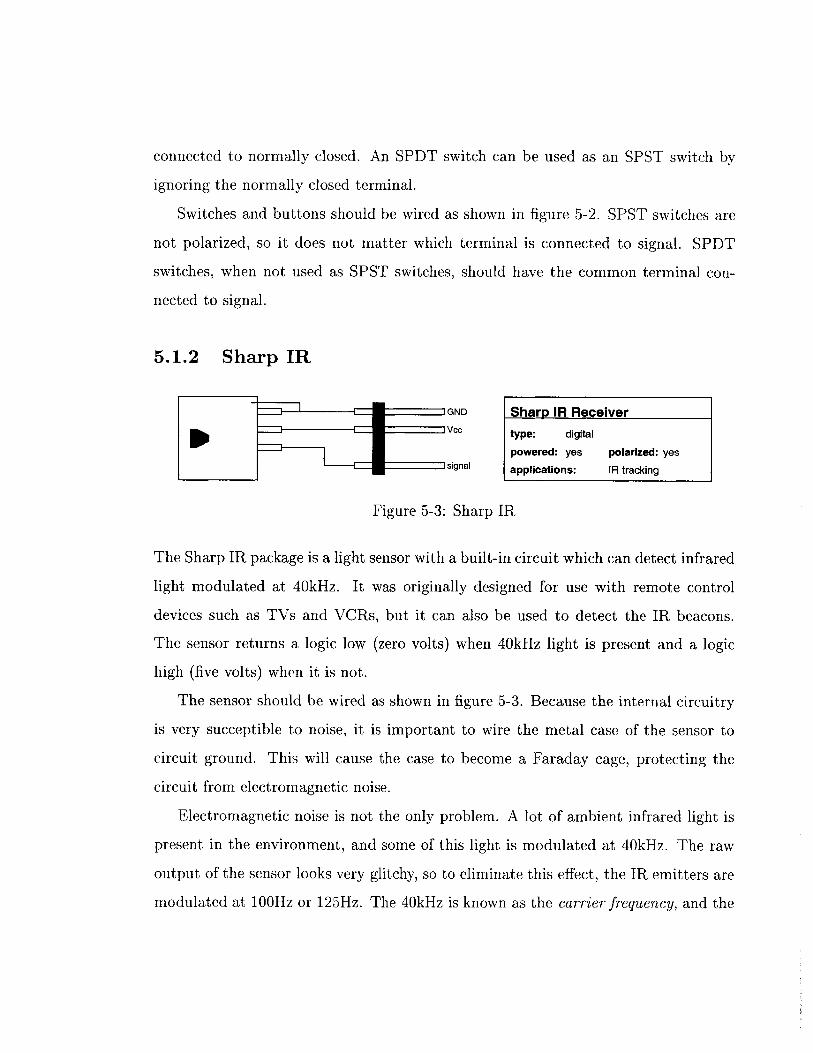
connected to normally closed. An SPDT switch can be used as an SPST switch by
ignoring the normally closed terminal.
Switches and buttons should be wired as shown in figure 5-2. SPST switches are
not polarized, so it does not matter which terminal is connected to signal. SPDT
switches, when not used as SPST switches, should have the common terminal con-
nected to signal.
5.1.2 Sharp IR
GND Sharp IR Receiver-vC type: digital
powered: yes polarized: yessignal applications: IR tracking
Figure 5-3: Sharp IR
The Sharp IR package is a light sensor with a built-in circuit which can detect infrared
light modulated at 40kHz. It was originally designed for use with remote control
devices such as TVs and VCRs, but it can also be used to detect the IR beacons.
The sensor returns a logic low (zero volts) when 40kHz light is present and a logic
high (five volts) when it is not.
The sensor should be wired as shown in figure 5-3. Because the internal circuitry
is very succeptible to noise, it is important to wire the metal case of the sensor to
circuit ground. This will cause the case to become a Faraday cage, protecting the
circuit from electromagnetic noise.
Electromagnetic noise is not the only problem. A lot of ambient infrared light is
present in the environment, and some of this light is modulated at 40kHz. The raw
output of the sensor looks very glitchy, so to eliminate this effect, the IR emitters are
modulated at 100Hz or 125Hz. The 40kHz is known as the carrier frequency, and the
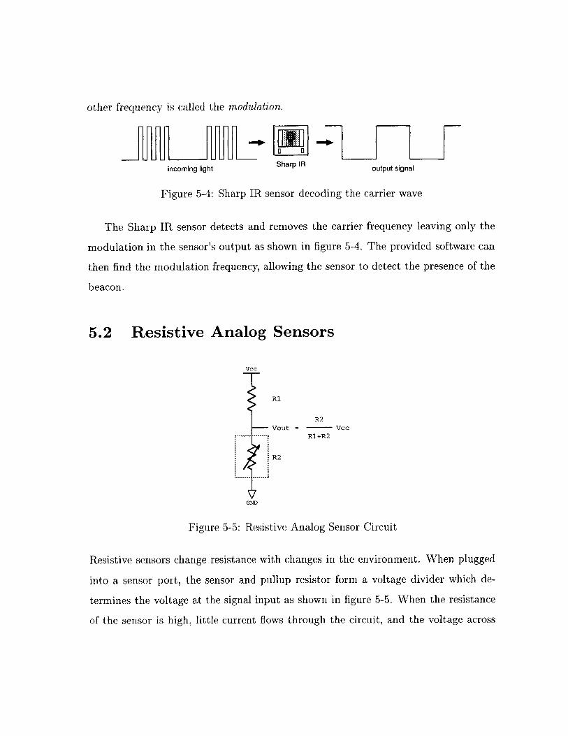
other frequency is called the modulation.
incoming light Sharp IR output signal
Figure 5-4: Sharp IR sensor decoding the carrier wave
The Sharp IR sensor detects and removes the carrier frequency leaving only the
modulation in the sensor's output as shown in figure 5-4. The provided software can
then find the modulation frequency, allowing the sensor to detect the presence of the
beacon.
5.2 Resistive Analog Sensors
Vcc
R1
R2Vout = Vcc
.-------.------- R1+R2
R2
GND
Figure 5-5: Resistive Analog Sensor Circuit
Resistive sensors change resistance with changes in the environment. When plugged
into a sensor port, the sensor and pullup resistor form a voltage divider which de-
termines the voltage at the signal input as shown in figure 5-5. When the resistance
of the sensor is high, little current flows through the circuit, and the voltage across
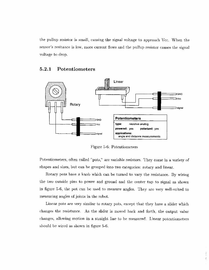
the pullup resistor is small, causing the signal voltage to approach Vcc. When the
sensor's resitance is low, more current flows and the pullup resistor causes the signal
voltage to drop.
5.2.1 Potentiometers
GND
Rotary----- ----- signal
GND PotentiometersvcC type: resistive analog
powered: yes polarized: yes
signal applications:angle and distance measurements
Figure 5-6: Potentiometers
Potentiometers, often called "pots," are variable resistors. They come in a variety of
shapes and sizes, but can be grouped into two categories: rotary and linear.
Rotary pots have a knob which can be turned to vary the resistance. By wiring
the two outside pins to power and ground and the center tap to signal as shown
in figure 5-6, the pot can be used to measure angles. They are very well-suited to
measuring angles of joints in the robot.
Linear pots are very similar to rotary pots, except that they have a slider which
changes the resistance. As the slider is moved back and forth, the output value
changes, allowing motion in a straight line to be measured. Linear potentiometers
should be wired as shown in figure 5-6.
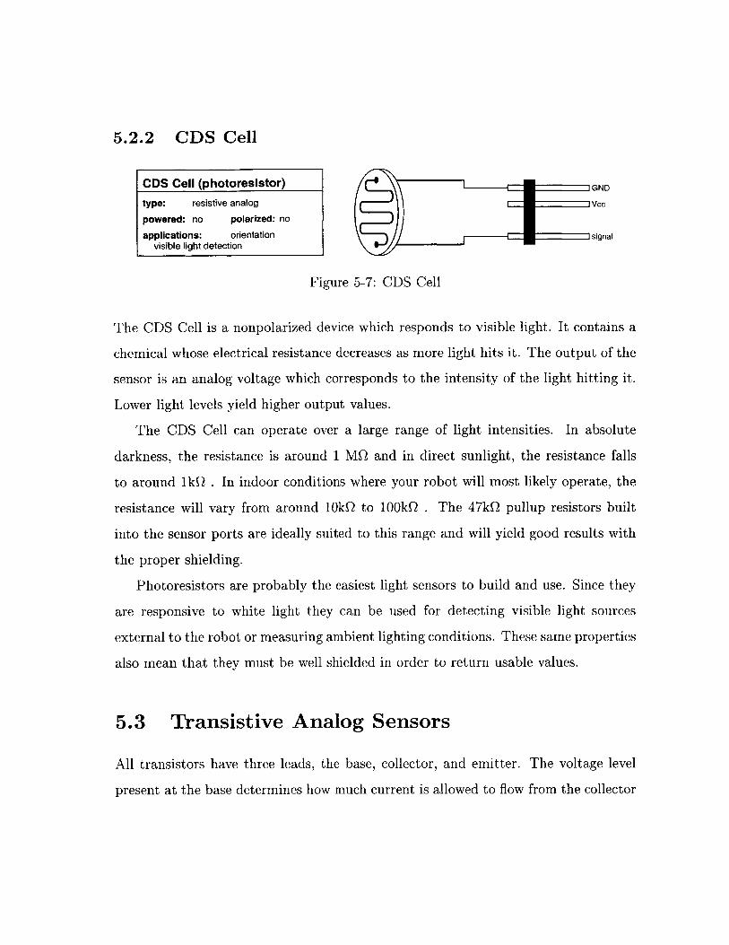
5.2.2 CDS Cell
CDS Cell (photoresistor) GND
type: resistive analog vc
powered: no polarized: no
applications: orientation signalvisible light detection
Figure 5-7: CDS Cell
The CDS Cell is a nonpolarized device which responds to visible light. It contains a
chemical whose electrical resistance decreases as more light hits it. The output of the
sensor is an analog voltage which corresponds to the intensity of the light hitting it.
Lower light levels yield higher output values.
The CDS Cell can operate over a large range of light intensities. In absolute
darkness, the resistance is around 1 MQ and in direct sunlight, the resistance falls
to around 1kQ . In indoor conditions where your robot will most likely operate, the
resistance will vary from around 1OkQ to 1OOkQ . The 47kQ pullup resistors built
into the sensor ports are ideally suited to this range and will yield good results with
the proper shielding.
Photoresistors are probably the easiest light sensors to build and use. Since they
are responsive to white light they can be used for detecting visible light sources
external to the robot or measuring ambient lighting conditions. These same properties
also mean that they must be well shielded in order to return usable values.
5.3 Transistive Analog Sensors
All transistors have three leads, the base, collector, and emitter. The voltage level
present at the base determines how much current is allowed to flow from the collector
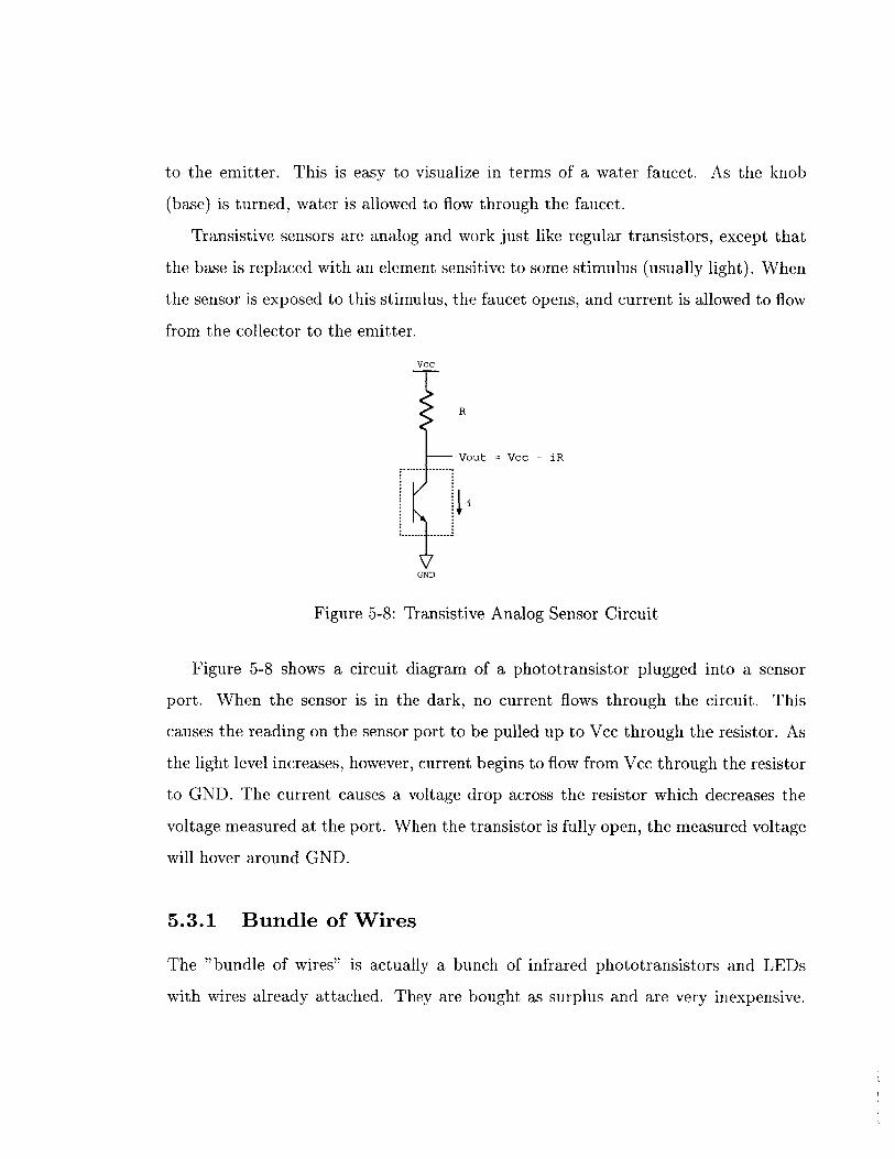
to the emitter. This is easy to visualize in terms of a water faucet. As the knob
(base) is turned, water is allowed to flow through the faucet.
Transistive sensors are analog and work just like regular transistors, except that
the base is replaced with an element sensitive to some stimulus (usually light). When
the sensor is exposed to this stimulus, the faucet opens, and current is allowed to flow
from the collector to the emitter.
VcC
R
Vout = Vcc - iR
GND
Figure 5-8: Transistive Analog Sensor Circuit
Figure 5-8 shows a circuit diagram of a phototransistor plugged into a sensor
port. When the sensor is in the dark, no current flows through the circuit. This
causes the reading on the sensor port to be pulled up to Vcc through the resistor. As
the light level increases, however, current begins to flow from Vcc through the resistor
to GND. The current causes a voltage drop across the resistor which decreases the
voltage measured at the port. When the transistor is fully open, the measured voltage
will hover around GND.
5.3.1 Bundle of Wires
The "bundle of wires" is actually a bunch of infrared phototransistors and LEDs
with wires already attached. They are bought as surplus and are very inexpensive.
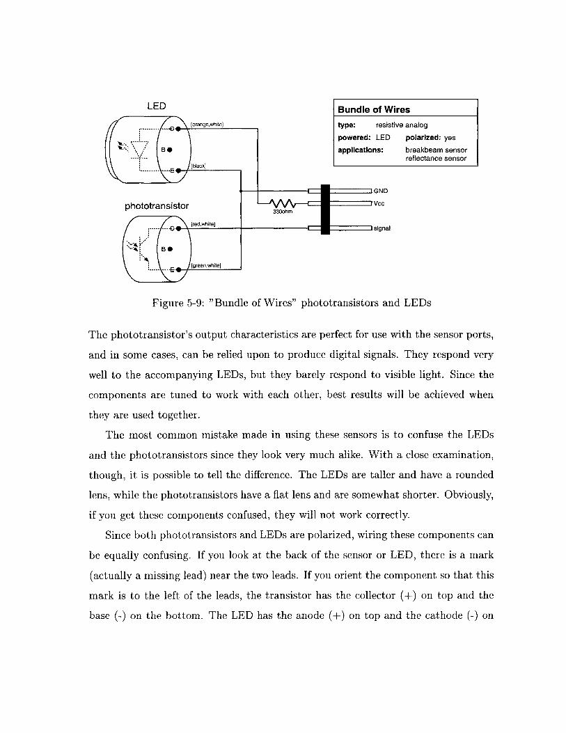
LED
GND
phototransistor vcc
[ree,white]
'gred hwsignal
Figure 5-9: "Bundle of Wires" phototransistors and LEDs
The phototransistor's output characteristics are perfect for use with the sensor ports,
and in some cases, can be relied upon to produce digital signals. They respond very
well to the accompanying LEDs, but they barely respond to visible light. Since the
components are tuned to work with each other, best results will be achieved when
they are used together.
The most common mistake made in using these sensors is to confuse the LEDs
and the phototransistors since they look very much alike. With a close examination,
though, it is possible to tell the difference. The LEDs are taller and have a rounded
lens, while the phototransistors have a flat lens and are somewhat shorter. Obviously,
if you get these components confused, they will not work correctly.
Since both phototransistors and LEDs are polarized, wiring these components can
be equally confusing. If you look at the back of the sensor or LED, there is a mark
(actually a missing lead) near the two leads. If you orient the component so that this
mark is to the left of the leads, the transistor has the collector (+) on top and the
base (-) on the bottom. The LED has the anode (+) on top and the cathode (-) on
Bundle of Wires
type: resistive analog
powered: LED polarized: yes
applications: breakbeam sensorreflectance sensor
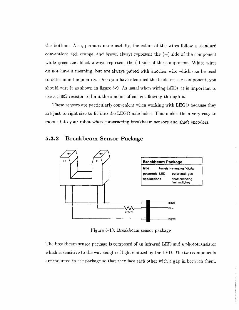
the bottom. Also, perhaps more usefully, the colors of the wires follow a standard
convention: red, orange, and brown always represent the (+) side of the component
while green and black always represent the (-) side of the component. White wires
do not have a meaning, but are always paired with another wire which can be used
to determine the polarity. Once you have identified the leads on the component, you
should wire it as shown in figure 5-9. As usual when wiring LEDs, it is important to
use a 330Q resistor to limit the amount of current flowing through it.
These sensors are particularly convenient when working with LEGO because they
are just to right size to fit into the LEGO axle holes. This makes them very easy to
mount into your robot when constructing breakbeam sensors and shaft encoders.
5.3.2 Breakbeam Sensor Package
DE -Breakbeam Packagetype: transistive analog / digital
powered: LED polarized: yes
applications: shaft encodinglimit switches
GND
t330ohm
sgasignal
Figure 5-10: Breakbeam sensor package
The breakbeam sensor package is composed of an infrared LED and a phototransistor
which is sensitive to the wavelength of light emitted by the LED. The two components
are mounted in the package so that they face each other with a gap in between them.
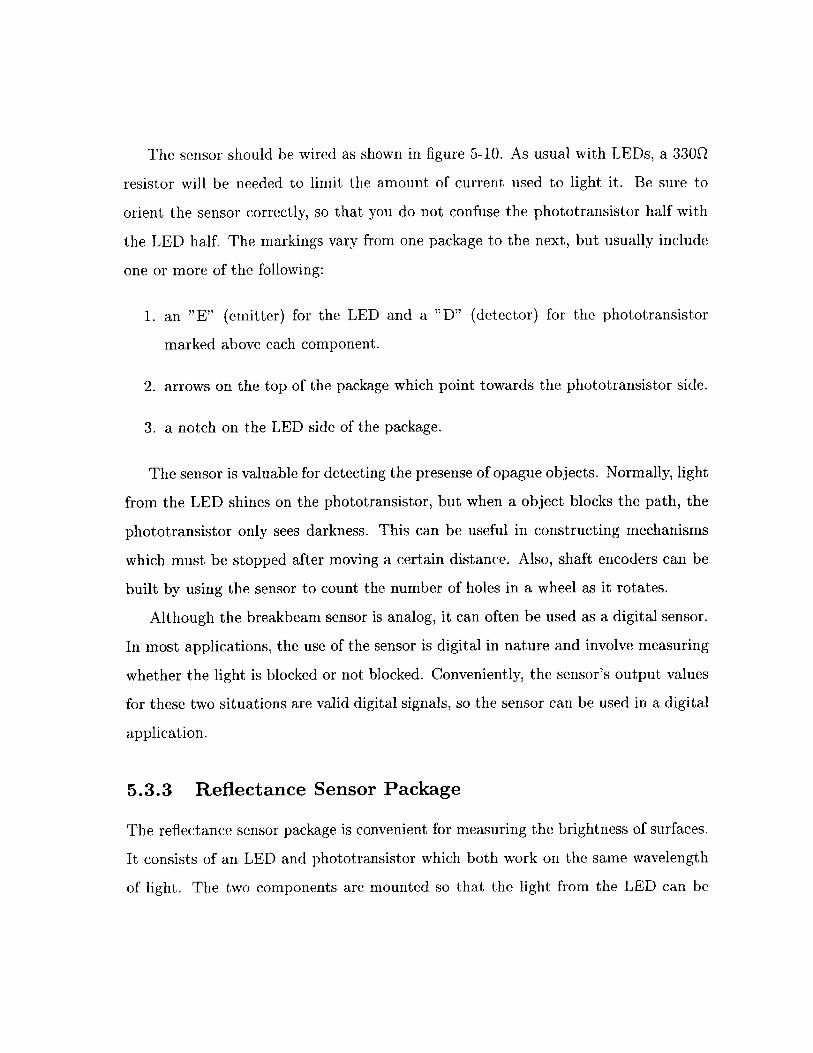
The sensor should be wired as shown in figure 5-10. As usual with LEDs, a 330Q
resistor will be needed to limit the amount of current used to light it. Be sure to
orient the sensor correctly, so that you do not confuse the phototransistor half with
the LED half. The markings vary from one package to the next, but usually include
one or more of the following:
1. an "E" (emitter) for the LED and a "D" (detector) for the phototransistor
marked above each component.
2. arrows on the top of the package which point towards the phototransistor side.
3. a notch on the LED side of the package.
The sensor is valuable for detecting the presense of opague objects. Normally, light
from the LED shines on the phototransistor, but when a object blocks the path, the
phototransistor only sees darkness. This can be useful in constructing mechanisms
which must be stopped after moving a certain distance. Also, shaft encoders can be
built by using the sensor to count the number of holes in a wheel as it rotates.
Although the breakbeam sensor is analog, it can often be used as a digital sensor.
In most applications, the use of the sensor is digital in nature and involve measuring
whether the light is blocked or not blocked. Conveniently, the sensor's output values
for these two situations are valid digital signals, so the sensor can be used in a digital
application.
5.3.3 Reflectance Sensor Package
The reflectance sensor package is convenient for measuring the brightness of surfaces.
It consists of an LED and phototransistor which both work on the same wavelength
of light. The two components are mounted so that the light from the LED can be
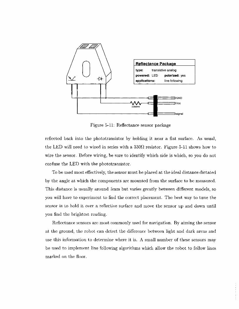
GND
Vcc330ohm
C
signal
Figure 5-11: Reflectance sensor package
reflected back into the phototransistor by holding it near a flat surface. As usual,
the LED will need to wired in series with a 330Q resistor. Figure 5-11 shows how to
wire the sensor. Before wiring, be sure to identify which side is which, so you do not
confuse the LED with the phototransistor.
To be used most effectively, the sensor must be placed at the ideal distance dictated
by the angle at which the components are mounted from the surface to be measured.
This distance is usually around 5mm but varies greatly between different models, so
you will have to experiment to find the correct placement. The best way to tune the
sensor is to hold it over a reflective surface and move the sensor up and down until
you find the brightest reading.
Reflectance sensors are most commonly used for navigation. By aiming the sensor
at the ground, the robot can detect the difference between light and dark areas and
use this information to determine where it is. A small number of these sensors may
be used to implement line following algorithms which allow the robot to follow lines
marked on the floor.
Reflectance Package
type: transistive analog
powered: LED polarized: yes
applications: line following
Chapter 6
Robot Construction
Most people consider LEGO to be a childhood toy, but the LEGO Technic system
provides an excellent construction material for building robots. Since the pieces can
be taken apart as easily as they are put together, no design must ever be final. It frees
you from drawing out detailed plans and machining parts, so you can spend more
time learning about and designing your robot. You can experiment with building,
redesigning, and rebuilding components of your robot until you are satisfied with the
results.
The best way to learn how to build with LEGO pieces is to play with them,
but this chapter will present an introduction to a number of building techniques and
design ideas. It is meant to provide you with the basic knowledge you will need
to begin exploring and learning on your own. Reading this chapter, however, is no
substitute for actual hands-on experience.
75
6.1 Design Concepts
When beginning work on a task as complex as building a robot, it helps to follow
good design techniques. Although it requires continual practice to hone these skills,
keeping the following ideas in mind while you build can help you produce a successful
robot:
" Simplicity. The best way to build a reliable robot is to keep it as simple as is
reasonably possible. In general, the more complicated a design is, the harder it
is to build, and the more prone it is to failure. Try to minimize the number of
moving parts and the overall complexity of the robot.
" Strength. During the course of operating and transporting your robot, it will
be bumped and handled quite often. This can easily damage the robot and cause
its performance to degrade over time. Building a strong robot will minimize
the amount of time spent on repairs and will improve its overall performance.
" Modularity. Often, it will be necessary to upgrade or repair a component
of the robot, but if the robot is built as one monolithic unit this may make it
necessary to disassemble a substantial portion of the structure. If, however, you
design your robot as a group of connected modules, the appropriate module can
simply be removed and rebuilt.
6.2 The LEGO Technic System
The Technic system is similar to the LEGO parts that you may have played with as a
child, except that in addition to the regular bricks and plates, this set includes pieces
for building more complicated structures and moving parts. These components allow
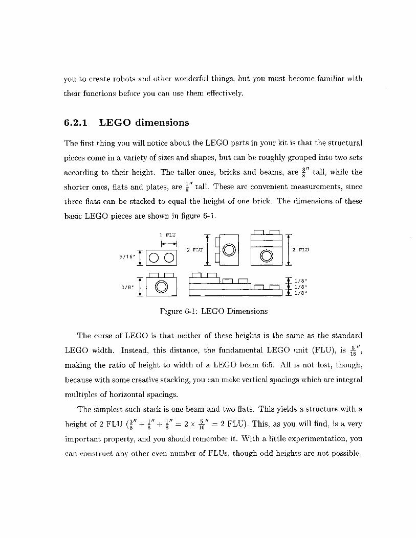
you to create robots and other wonderful things, but you must become familiar with
their functions before you can use them effectively.
6.2.1 LEGO dimensions
The first thing you will notice about the LEGO parts in your kit is that the structural
pieces come in a variety of sizes and shapes, but can be roughly grouped into two sets
according to their height. The taller ones, bricks and beams, are i" tall, while the
shorter ones, flats and plates, are " tall. These are convenient measurements, since
three flats can be stacked to equal the height of one brick. The dimensions of these
basic LEGO pieces are shown in figure 6-1.
1 FLU --
2 FLU 2 FLU5 /16 " 0
3/8" l 1/8"_ 1 1/8"
Figure 6-1: LEGO Dimensions
The curse of LEGO is that neither of these heights is the same as the standard
LEGO width. Instead, this distance, the fundamental LEGO unit (FLU), is A",making the ratio of height to width of a LEGO beam 6:5. All is not lost, though,
because with some creative stacking, you can make vertical spacings which are integral
multiples of horizontal spacings.
The simplest such stack is one beam and two flats. This yields a structure with a
height of 2 FLU (I" + + " = 2 x "= 2 FLU). This, as you will find, is a very8 8 5 16
important property, and you should remember it. With a little experimentation, you
can construct any other even number of FLUs, though odd heights are not possible.
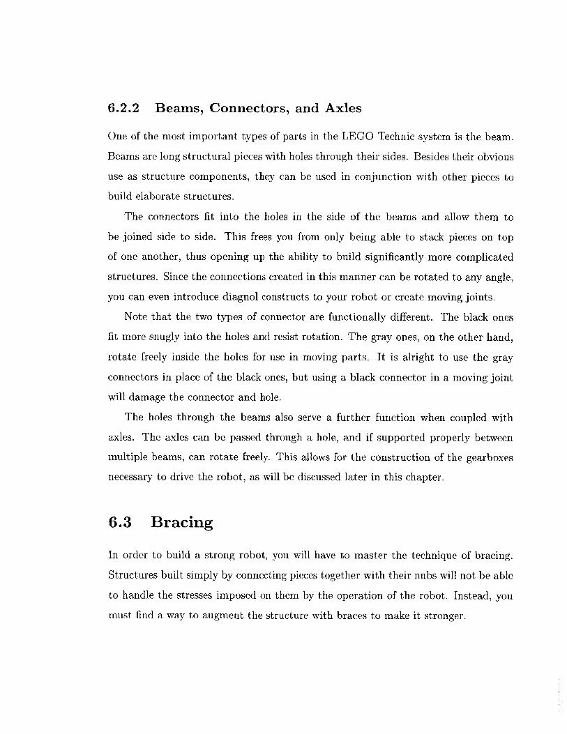
6.2.2 Beams, Connectors, and Axles
One of the most important types of parts in the LEGO Technic system is the beam.
Beams are long structural pieces with holes through their sides. Besides their obvious
use as structure components, they can be used in conjunction with other pieces to
build elaborate structures.
The connectors fit into the holes in the side of the beams and allow them to
be joined side to side. This frees you from only being able to stack pieces on top
of one another, thus opening up the ability to build significantly more complicated
structures. Since the connections created in this manner can be rotated to any angle,
you can even introduce diagnol constructs to your robot or create moving joints.
Note that the two types of connector are functionally different. The black ones
fit more snugly into the holes and resist rotation. The gray ones, on the other hand,
rotate freely inside the holes for use in moving parts. It is alright to use the gray
connectors in place of the black ones, but using a black connector in a moving joint
will damage the connector and hole.
The holes through the beams also serve a further function when coupled with
axles. The axles can be passed through a hole, and if supported properly between
multiple beams, can rotate freely. This allows for the construction of the gearboxes
necessary to drive the robot, as will be discussed later in this chapter.
6.3 Bracing
In order to build a strong robot, you will have to master the technique of bracing.
Structures built simply by connecting pieces together with their nubs will not be able
to handle the stresses imposed on them by the operation of the robot. Instead, you
must find a way to augment the structure with braces to make it stronger.
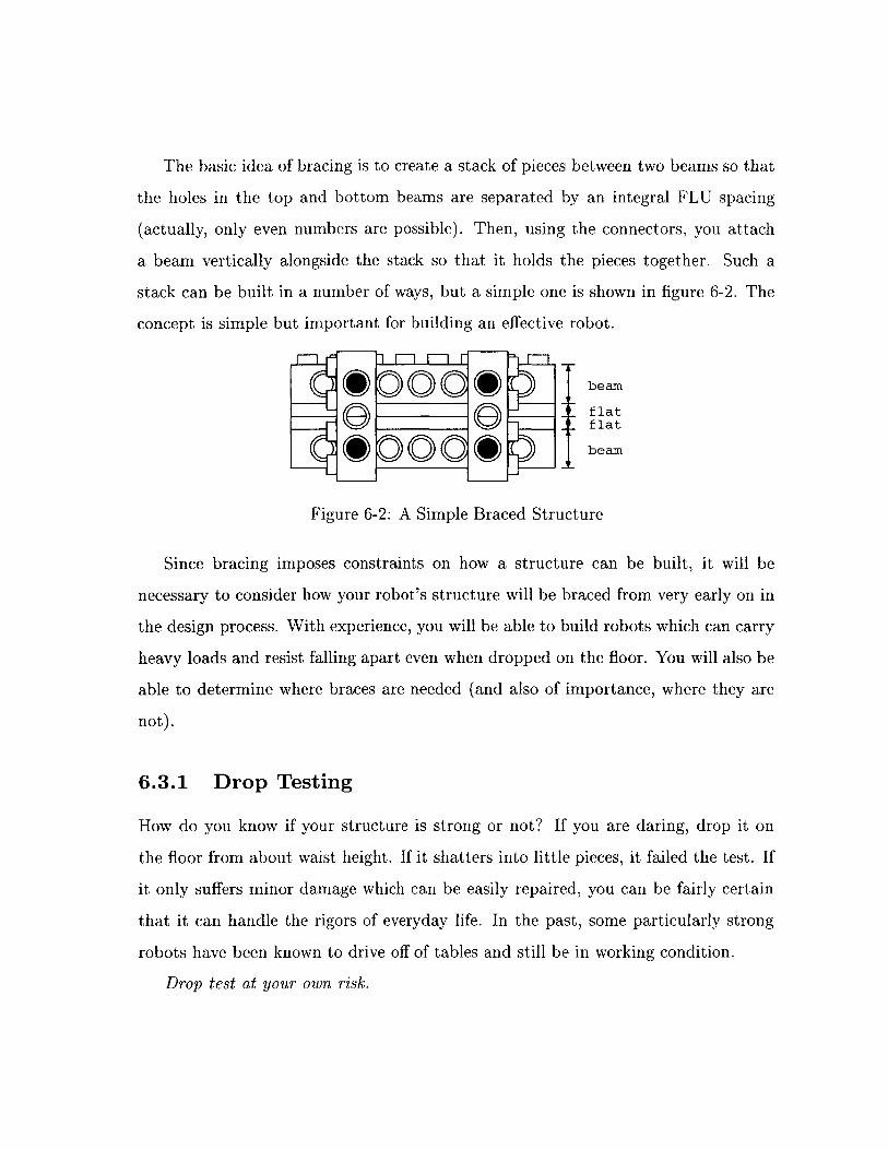
The basic idea of bracing is to create a stack of pieces between two beams so that
the holes in the top and bottom beams are separated by an integral FLU spacing
(actually, only even numbers are possible). Then, using the connectors, you attach
a beam vertically alongside the stack so that it holds the pieces together. Such a
stack can be built in a number of ways, but a simple one is shown in figure 6-2. The
concept is simple but important for building an effective robot.
, DO0 \91- 0 beam
f lat
1 0 1\01beam
Figure 6-2: A Simple Braced Structure
Since bracing imposes constraints on how a structure can be built, it will be
necessary to consider how your robot's structure will be braced from very early on in
the design process. With experience, you will be able to build robots which can carry
heavy loads and resist falling apart even when dropped on the floor. You will also be
able to determine where braces are needed (and also of importance, where they are
not) .
6.3.1 Drop Testing
How do you know if your structure is strong or not? If you are daring, drop it on
the floor from about waist height. If it shatters into little pieces, it failed the test. If
it only suffers minor damage which can be easily repaired, you can be fairly certain
that it can handle the rigors of everyday life. In the past, some particularly strong
robots have been known to drive off of tables and still be in working condition.
Drop test at your own risk.
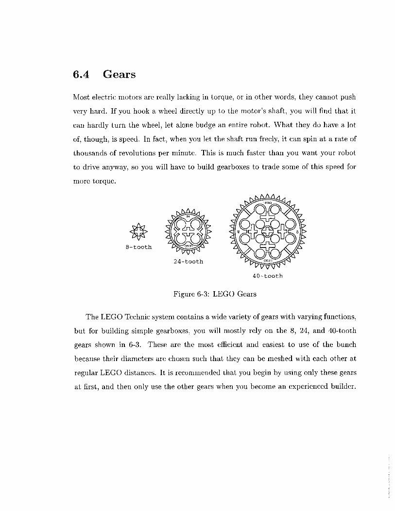
6.4 Gears
Most electric motors are really lacking in torque, or in other words, they cannot push
very hard. If you hook a wheel directly up to the motor's shaft, you will find that it
can hardly turn the wheel, let alone budge an entire robot. What they do have a lot
of, though, is speed. In fact, when you let the shaft run freely, it can spin at a rate of
thousands of revolutions per minute. This is much faster than you want your robot
to drive anyway, so you will have to build gearboxes to trade some of this speed for
more torque.
LEGO
24
8-tooth S024-tooth 003
40-tooth
Figure 6-3: LEGO Gears
The LEGO Technic system contains a wide variety of gears with varying functions,
but for building simple gearboxes, you will mostly rely on the 8, 24, and 40-tooth
gears shown in 6-3. These are the most efficient and easiest to use of the bunch
because their diameters are chosen such that they can be meshed with each other at
regular LEGO distances. It is recommended that you begin by using only these gears
at first, and then only use the other gears when you become an experienced builder.
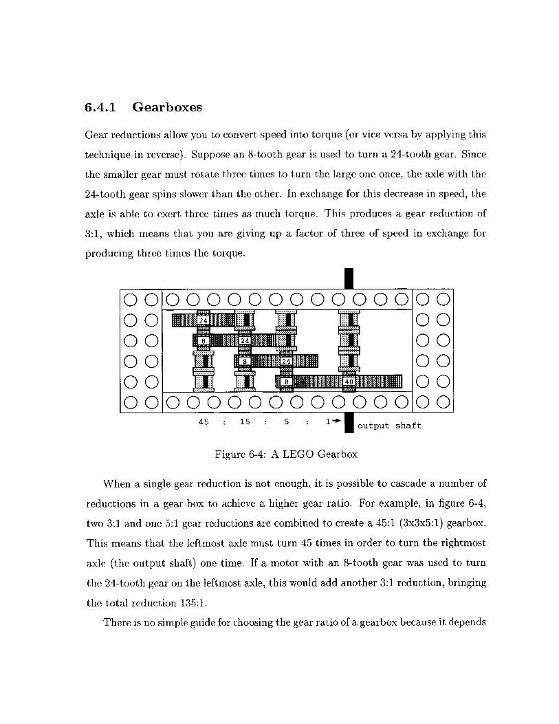
6.4.1 Gearboxes
Gear reductions allow you to convert speed into torque (or vice versa by applying this
technique in reverse). Suppose an 8-tooth gear is used to turn a 24-tooth gear. Since
the smaller gear must rotate three times to turn the large one once, the axle with the
24-tooth gear spins slower than the other. In exchange for this decrease in speed, the
axle is able to exert three times as much torque. This produces a gear reduction of
3:1, which means that you are giving up a factor of three of speed in exchange for
producing three times the torque.
000000...00...000000-00
00 8ti ti 0000 00
00 000000000000
45 15 5 o I ouoput shaft
Figure 6-4: A LEGO Gearbox
When a single gear reduction is not enough, it is possible to cascade a number of
reductions in a gear box to achieve a higher gear ratio. For example, in figure 6-4,
two 3:1 and one 5:1 gear reductions are combined to create a 45:1 (3x3x5:1) gearbox.
This means that the leftmost axle must turn 45 times in order to turn the rightmost
axle (the output shaft) one time. If a motor with an 8-tooth gear was used to turn
the 24-tooth gear on the leftmost axle, this would add another 3:1 reduction, bringing
the total reduction 135:1.
There is no simple guide for choosing the gear ratio of a gearbox because it depends
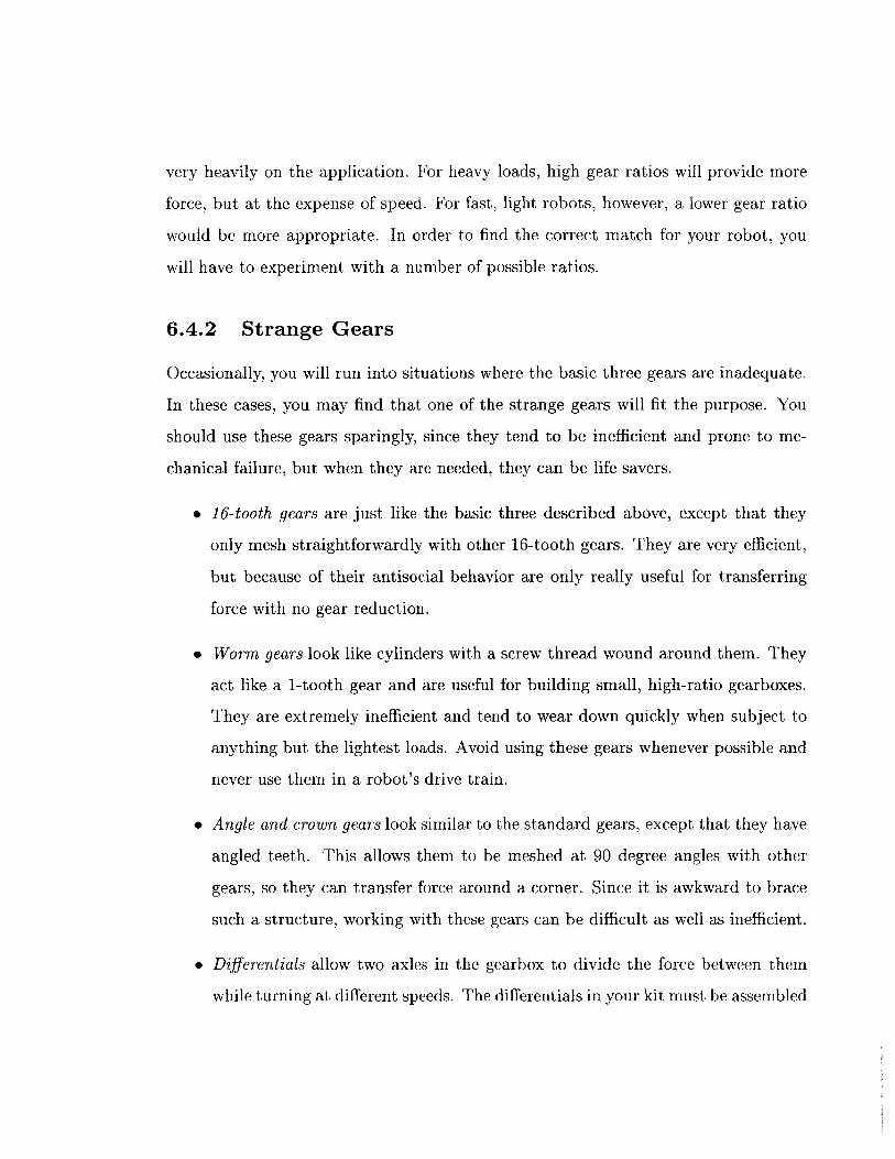
very heavily on the application. For heavy loads, high gear ratios will provide more
force, but at the expense of speed. For fast, light robots, however, a lower gear ratio
would be more appropriate. In order to find the correct match for your robot, you
will have to experiment with a number of possible ratios.
6.4.2 Strange Gears
Occasionally, you will run into situations where the basic three gears are inadequate.
In these cases, you may find that one of the strange gears will fit the purpose. You
should use these gears sparingly, since they tend to be inefficient and prone to me-
chanical failure, but when they are needed, they can be life savers.
" 16-tooth gears are just like the basic three described above, except that they
only mesh straightforwardly with other 16-tooth gears. They are very efficient,
but because of their antisocial behavior are only really useful for transferring
force with no gear reduction.
" Worm gears look like cylinders with a screw thread wound around them. They
act like a 1-tooth gear and are useful for building small, high-ratio gearboxes.
They are extremely inefficient and tend to wear down quickly when subject to
anything but the lightest loads. Avoid using these gears whenever possible and
never use them in a robot's drive train.
* Angle and crown gears look similar to the standard gears, except that they have
angled teeth. This allows them to be meshed at 90 degree angles with other
gears, so they can transfer force around a corner. Since it is awkward to brace
such a structure, working with these gears can be difficult as well as inefficient.
" Differentials allow two axles in the gearbox to divide the force between them
while turning at different speeds. The differentials in your kit must be assembled
by placing three angle gears inside the differential casing. Because of their
complexity, they can be difficult to build into a gearbox, but they do fulfill a
purpose that no other gear can peform.
6.4.3 Chain Drives and Pulleys
The chain drive is an invaluable tool for transferring motion from one place to another.
It is assembled from the small connectable links and two or more regular gears (usually
the 24 or 40-tooth gears). This allows it to transfer force from one gear to another.
Unfortunately, though, the chain links are not sized to standard LEGO dimensions,
so trial and error is often necessary to find a workable gear spacing. If the chain is
too loose, it may skip under heavy load, and if it is too tight, you will lose power.
Since the chain drive tends to be a bit inefficient, it is best when used in the lower
stages of a geartrain.
0 0 0 00 0
Figure 6-5: LEGO Pulleys
Pulley systems work in a similar manner and can be built using the pulley wheels
shown in figure 6-5 with a string or rubberband. They allow a great deal more
flexibility in their arrangement than the chain drive, but they tend to slip easily
under a load. They work best when used in the upper stages of a geartrain where
there is the least amount of force. Be sure to make the string or rubberband the
correct length. If it is the slightest bit too loose, it tends to slip, and if it is too tight,
it will lose efficiency.
6.4.4 Efficiency
The biggest enemy of any gearbox is friction. Every place where something rubs,
energy is lost which makes your robot slower and weaker. In the short-run, this
causes your robot to perform poorly, but in the long-run, it will cause wear and tear
on the moving parts. More damage means more friction, and after awhile, the gearbox
will stop working. In order to minimize the amount of friction in your gearbox and
maximize its efficiency, follow the tips below:
1. The spacing between gears is very important. If they are too close to each other,
they will bind up. If they are too far, the teeth will slip past each other. Make
sure that gears are spaced at exact LEGO dimensions and avoid meshing gears
at an angle.
2. The axles are made out of plastic and can bend if not properly supported. Try
to always support the axle between two beams and do not place a gear more
than one space outside of the supports.
3. The gearbox will often be subjected to stresses when used within a robot. Make
sure that the beams supporting the axles are attached to each other with more
than one cross-support and that the whole structure is braced. If the beams
are not perfectly parallel, the axles will rub against the insides of the holes.
4. During operation the gears can slide along the axle or bump into nearby gears.
Use spacers to fill in any empty spots along the axle.
5. Make sure that the axles can slide back and forth a tiny bit. If they cannot, the
gears or spacers are probably pushing up against a beam. This is probably the
most common (and easiest to fix) mistake which saps efficiency from a gearbox.
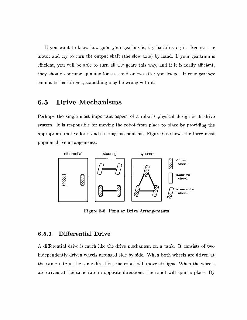
If you want to know how good your gearbox is, try backdriving it. Remove the
motor and try to turn the output shaft (the slow axle) by hand. If your geartrain is
efficient, you will be able to turn all the gears this way, and if it is really efficient,
they should continue spinning for a second or two after you let go. If your gearbox
cannot be backdriven, something may be wrong with it.
6.5 Drive Mechanisms
Perhaps the single most important aspect of a robot's physical design is its drive
system. It is responsible for moving the robot from place to place by providing the
appropriate motive force and steering mechanisms. Figure 6-6 shows the three most
popular drive arrangements.
differential steering synchroO drive
wheel
passivewheel
s teerablewheel
Figure 6-6: Popular Drive Arrangements
6.5.1 Differential Drive
A differential drive is much like the drive mechanism on a tank. It consists of two
independently driven wheels arranged side by side. When both wheels are driven at
the same rate in the same direction, the robot will move straight. When the wheels
are driven at the same rate in opposite directions, the robot will spin in place. By
varying the relative speeds of the two wheels, any turning radius is achievable. Since
this system minimizes the number of moving parts, it tends to be the simplest and
most robust. The complexity is increased slightly, though, by the need for a caster
in the front or back of the robot to keep it from tipping over.
An especially useful property of this drive system is that the change in orientation
of the robot depends only on the difference between the distances travelled by each of
the wheels. It does not matter if the left wheel moves forward 10cm and the right back
10cm, or if only the left wheel moves forward 20cm; the final location will be different,
but the orientation will be the same (ignoring slippage). This greatly simplifies the
process of turning, by making the final orientation of the robot easily predictable.
The differential drive is the most popular because of its simplicity, though it does
have some limitations. Since it is difficult to calculate the final location of the robot
if it turns and moves at the same time, most navigation algorithms consist of driving
straight for a distance, turning through a specified angle in place, and then driving
straight again. More sophisticated algorithms allow the robot to turn while moving,
but typically, such turns are still constrained to easily calculated curves.
6.5.2 Steering System
Steering systems should already be familiar to you because they are widely used in
automobiles. They usually consist of one or two steerable wheels at the front of the
robot and two powered wheels at the rear. The turning radius is determined by the
angle of the steerable wheels, but the robot must be moving in order to make a turn.
This means that it cannot turn in place and can only make turns of limited sharpness
while driving.
The advantage to using a steering system comes from the separation of the steering
and drive mechanisms. Such robots tend to be quick and fairly agile. They are well-
suited to driving in open spaces or performing "follow" tasks since these tasks usually
require making course corrections to the left and right as the robot drives. When a
steering robot turns, though, the two rear wheels will take paths of different lengths.
The outer one will travel a longer distance than the inner one, so it is helpful to use
a differential in the gearbox to transfer force between the wheels in order to avoid
slippage.
6.5.3 Synchro Drive
The synchro drive is an exotic mechanism where all the wheels are driven and steered
together. Usually, there is one gearbox which turns the wheels to the desired ori-
entation and then another which drives the robot in that direction. This may seem
strange, but it allows the robot's instructinos to be phrased in terms of world coor-
dinates, instead of having to compute everything in terms of the robot's perspective.
The robot can also be commanded to move in any direction, making this the most
mobile of the drive systems.
This mechanism simplifies control at the expense of complexity in construction.
All the wheels must be both steerable and drivable, so building drivetrains for such
a system often requires an elaborate system of gears and chain drives. Also, since
only the wheels turn, the robot's body remains in a fixed orientation, unless it is
also turned. This makes it inconvenient for such a robot to have a front as many
applications require.
6.5.4 Legs
Robots with articulate legs can do everything that a wheeled robot can do and more.
This includes walking in arbitrary directions, turning in place, and even climbing over
otherwise inaccessible terrain. Unfortunately, though, legged robots are prohibitively
difficult to build out of LEGO and comparably difficult to control. In fact, a great
deal of research is currently being performed to study ways of making robots walk.
If you thing you are up to the challenge, by all means try it out, but be warned that
legs are much more complex than they appear.
Chapter 7
Robot Control
To the uninitiated, the term "robot" conjures up images of machines with human-like
abilities. Unfortunately, technology has not yet reached the point where robots can
mimic the intelligence of humans. Instead, the robot that you will be constructing
will require simple, step-by-step instructions for completing even the most simple of
tasks.
A robot's ability to interact with the environment centers around its sensors and
control system. The sensors convert information about the environment into a form
that can be used by a computer. They are limited in their abilities, however, and often
give back information that is cryptic, ambiguous, or even inaccurrate. The control
system must decode this information and determine the best course of action. The
task of endowing the control system with these abilities falls to you, the programmer.
This chapter will explore the design of systems for controlling a robot in a constantly
changing and unpredictable environment.
89
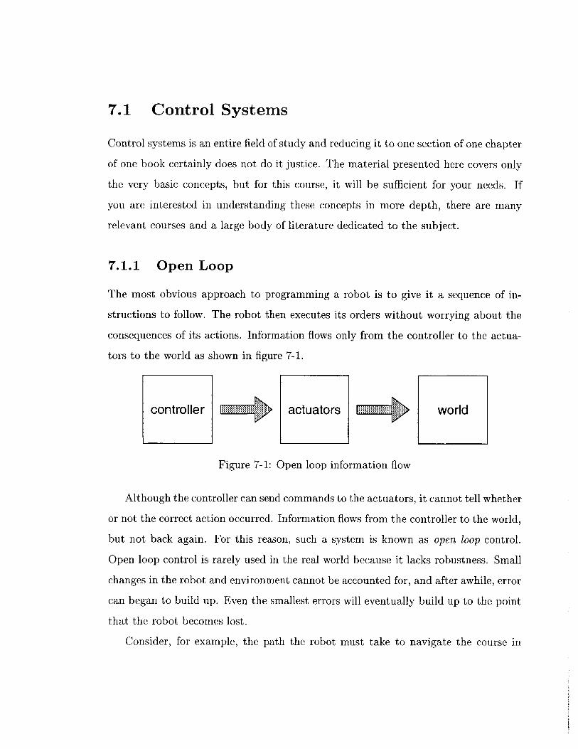
7.1 Control Systems
Control systems is an entire field of study and reducing it to one section of one chapter
of one book certainly does not do it justice. The material presented here covers only
the very basic concepts, but for this course, it will be sufficient for your needs. If
you are interested in understanding these concepts in more depth, there are many
relevant courses and a large body of literature dedicated to the subject.
7.1.1 Open Loop
The most obvious approach to programming a robot is to give it a sequence of in-
structions to follow. The robot then executes its orders without worrying about the
consequences of its actions. Information flows only from the controller to the actua-
tors to the world as shown in figure 7-1.
controller actuators world
Figure 7-1: Open loop information flow
Although the controller can send commands to the actuators, it cannot tell whether
or not the correct action occurred. Information flows from the controller to the world,
but not back again. For this reason, such a system is known as open loop control.
Open loop control is rarely used in the real world because it lacks robustness. Small
changes in the robot and environment cannot be accounted for, and after awhile, error
can began to build up. Even the smallest errors will eventually build up to the point
that the robot becomes lost.
Consider, for example, the path the robot must take to navigate the course in
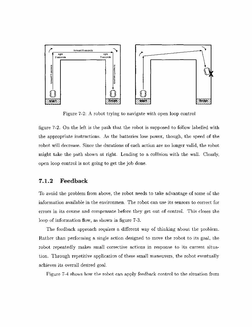
forward 8 seconds
right right3 seconds 3 seconds
'a'
aa
Figure 7-2: A robot trying to navigate with open loop control
figure 7-2. On the left is the path that the robot is supposed to follow labelled with
the appropriate instructions. As the batteries lose power, though, the speed of the
robot will decrease. Since the durations of each action are no longer valid, the robot
might take the path shown at right. Leading to a collision with the wall. Clearly,
open loop control is not going to get the job done.
7.1.2 Feedback
To avoid the problem from above, the robot needs to take advantage of some of the
information available in the environmen. The robot can use its sensors to correct for
errors in its course and compensate before they get out of control. This closes the
loop of information flow, as shown in figure 7-3.
The feedback approach requires a different way of thinking about the problem.
Rather than performing a single action designed to move the robot to its goal, the
robot repeatedly makes small corrective actions in response to its current situa-
tion. Through repetitive application of these small maneuvers, the robot eventually
achieves its overall desired goal.
Figure 7-4 shows how the robot can apply feedback control to the situation from
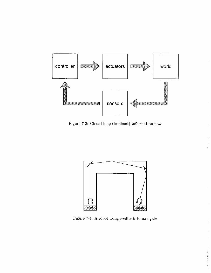
controller actuators world
sensors
Figure 7-3: Closed loop (feedback) information flow
Figure 7-4: A robot using feedback to navigate
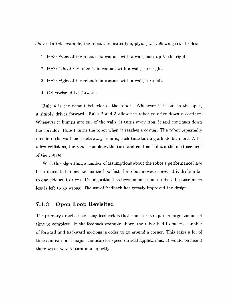
above. In this example, the robot is repeatedly applying the following set of rules:
1. If the front of the robot is in contact with a wall, back up to the right.
2. If the left of the robot is in contact with a wall, turn right.
3. If the right of the robot is in contact with a wall, turn left.
4. Otherwise, drive forward.
Rule 4 is the default behavior of the robot. Whenever it is out in the open,
it simply drives forward. Rules 2 and 3 allow the robot to drive down a corridor.
Whenever it bumps into one of the walls, it turns away from it and continues down
the corridor. Rule 1 turns the robot when it reaches a corner. The robot repeatedly
runs into the wall and backs away from it, each time turning a little bit more. After
a few collisions, the robot completes the turn and continues down the next segment
of the course.
With this algorithm, a number of assumptions about the robot's performance have
been relaxed. It does not matter how fast the robot moves or even if it drifts a bit
to one side as it drives. The algorithm has become much more robust because much
less is left to go wrong. The use of feedback has greatly improved the design.
7.1.3 Open Loop Revisited
The primary drawback to using feedback is that some tasks require a large amount of
time to complete. In the feedback example above, the robot had to make a number
of forward and backward motions in order to go around a corner. This takes a lot of
time and can be a major handicap for speed-critical applications. It would be nice if
there was a way to turn more quickly.
back 1 second, back 1 second,right 3 seconds right 3 seconds
Figure 7-5: A robot combining open loop and feedback control
Fortunately, open loop control may be good enough for some situations. Instead
of the feedback-only algorithm, a hybrid algorithm can be used as in figure 7-5. The
robot navigates the corridor using the feedback algorithm, except that when it runs
into a wall, it backs up a little and performs the quicker open loop turn instead of
the bumping method. After completing the turn, it then returns to the feedback
algorithm for navigating the next corridor.
As long as the open loop turn is accurate enough that the robot does not get
stuck in a corner, the feedback mechanism will be able to compensate for any error
that it introduces. Since the error is erased in this manner before the next open loop
command, it cannot snowball out of control like in the purely open loop algorithm.
By using this clever sandwiching of open loop and feedback control, it is possible to
develop an algorithm that has most of the efficiency of open loop control while only
sacrificing a little of the robustness of feedback control.
7.2 Sensors
Sensors allow a robot to collect information about the environment. They convert
physical measurements from the world into electrical signals that can be understood
by the controller. This gives the robot a link to the real world allowing it to respond
appropriately to changes in its environment.
7.2.1 Sensor Problems
The real world is a noisy place compared to the digital world of a computer, and
in robotics, this noise can make sensor readings unreliable. Sensor data mirrors the
nonideal nature of the robot's environment and must be interpretted by the computer.
Below are a few of the common types of errors that appear when reading sensors:
" Glitchy data is often a problem due to faults in the sensor hardware. When
a glitch occurs, the sensor may return an unexpected value or a value outside
of the range of possible values. Often, loose connector plugs or shorted wires
can cause spurious input by intermittantly losing or making contact. This can
be identified and fixed in software by ignoring values that fall outside of the
expected input.
" Noisy data is a problem for most sensors. The world is full of flickering lights,
uneven surfaces, and magnetic fields which can all cause errors in measurements.
Since noise tends to be a random process, there is no way to predict it, but its
effects can be minimized by averaging multiple values together when reading a
sensor.
" Drifting data is often the result of sensors retaining some sort of memory. This
problem is particularly prominant in light sensors which are affected by changes
in the ambient lighting of the room. As the robot moves from place to place,
the amount of light reaching the sensor can vary and change the range of the
measurements. Some light sensors are also sensitive to heat and return different
values as they warm up. These effects occur slowly over time, so they can be
very difficult to detect. One option is to give the robot the ability to recalibrate
itself whenever it finds itself in a known situation. This way, calibration values
can be updated on the fly as the robot moves from one part of the environment
to another.
7.2.2 Bouncing Switches
Most mechanical switches are afflicted with a phenomenon called bouncing. Wires are
not the ideal and instantaneous conductors that they are often modelled as. Instead,
when a circuit is broken, the electricity continues to flow for a few microseconds.
Since it has no place to go when it reaches the break, it bounces back and forth along
the wire a few times before it settles down. This causes voltage levels to rise and fall,
causing the sensor reading to transition a number of times (often dozens). A similar
effect also causes the switch to bounce when the circuit is reconnected.
In most circumstances, this does not cause a problem, but it can come into play
for operations like counting the number of times a button is pressed. If sampling is
performed too quickly, the computer can measure multiple counts when the button is
pressed just once. This problem can be solved in software by ignoring other transitions
that occur for a small amount of time after the first transition is detected. It can
also be solved in hardware by the addition of appropriate circuitry, but usually the
software fix will be sufficient.
7.2.3 Calibration
Light sensors are particularly sensitive to changes in the world. Differences in am-
bient lighting from one room to another can wreak havoc on the readings that the
sensor returns. When the robot needs to be moved from one environment to another,
calibration is often necessary to adjust the settings used to interpret the data.
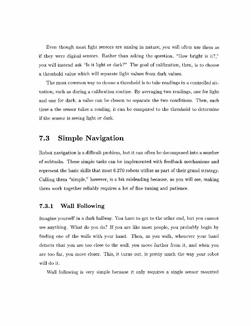
Even though most light sensors are analog in nature, you will often use them as
if they were digital sensors. Rather than asking the question, "How bright is it?,"
you will instead ask "Is it light or dark?" The goal of calibration, then, is to choose
a threshold value which will separate light values from dark values.
The most common way to choose a threshold is to take readings in a controlled sit-
uation, such as during a calibration routine. By averaging two readings, one for light
and one for dark, a value can be chosen to separate the two conditions. Then, each
time a the sensor takes a reading, it can be compared to the threshold to determine
if the sensor is seeing light or dark.
7.3 Simple Navigation
Robot navigation is a difficult problem, but it can often be decomposed into a number
of subtasks. These simple tasks can be implemented with feedback mechanisms and
represent the basic skills that most 6.270 robots utilize as part of their grand strategy.
Calling them "simple," however, is a bit misleading because, as you will see, making
them work together reliably requires a lot of fine tuning and patience.
7.3.1 Wall Following
Imagine yourself in a dark hallway. You have to get to the other end, but you cannot
see anything. What do you do? If you are like most people, you probably begin by
finding one of the walls with your hand. Then, as you walk, whenever your hand
detects that you are too close to the wall, you move farther from it, and when you
are too far, you move closer. This, it turns out, is pretty much the way your robot
will do it.
Wall following is very simple because it only requires a single sensor mounted
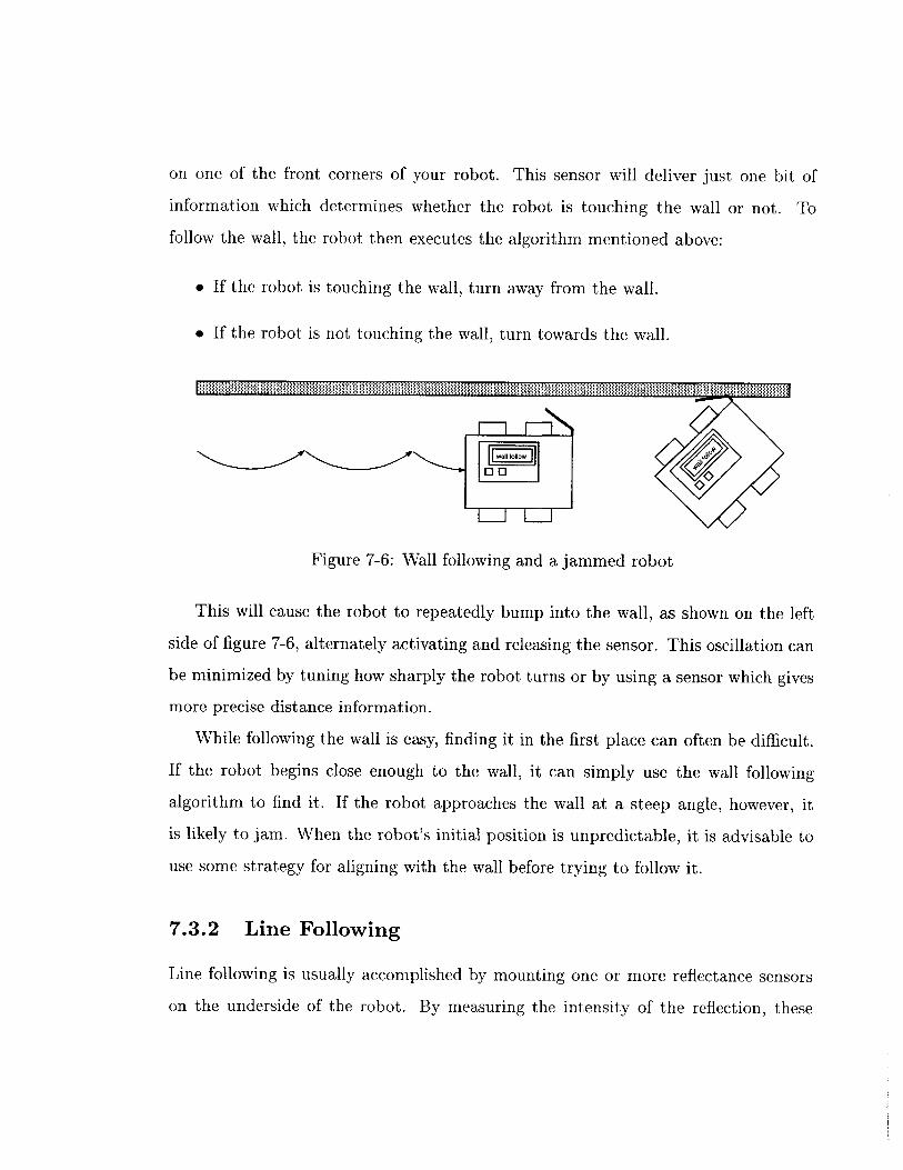
on one of the front corners of your robot. This sensor will deliver just one bit of
information which determines whether the robot is touching the wall or not. To
follow the wall, the robot then executes the algorithm mentioned above:
* If the robot is touching the wall, turn away from the wall.
o If the robot is not touching the wall, turn towards the wall.
0EI0
Figure 7-6: Wall following and a jammed robot
This will cause the robot to repeatedly bump into the wall, as shown on the left
side of figure 7-6, alternately activating and releasing the sensor. This oscillation can
be minimized by tuning how sharply the robot turns or by using a sensor which gives
more precise distance information.
While following the wall is easy, finding it in the first place can often be difficult.
If the robot begins close enough to the wall, it can simply use the wall following
algorithm to find it. If the robot approaches the wall at a steep angle, however, it
is likely to jam. When the robot's initial position is unpredictable, it is advisable to
use some strategy for aligning with the wall before trying to follow it.
7.3.2 Line Following
Line following is usually accomplished by mounting one or more reflectance sensors
on the underside of the robot. By measuring the intensity of the reflection, these
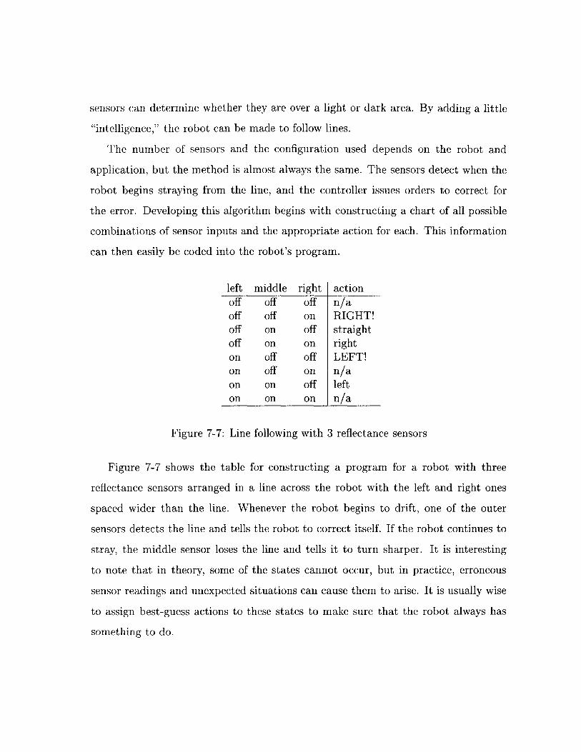
sensors can determine whether they are over a light or dark area. By adding a little
"intelligence," the robot can be made to follow lines.
The number of sensors and the configuration used depends on the robot and
application, but the method is almost always the same. The sensors detect when the
robot begins straying from the line, and the controller issues orders to correct for
the error. Developing this algorithm begins with constructing a chart of all possible
combinations of sensor inputs and the appropriate action for each. This information
can then easily be coded into the robot's program.
left middle right actionoff off off n/aoff off on RIGHT!off on off straightoff on on righton off off LEFT!on off on n/aon on off lefton on on n/a
Figure 7-7: Line following with 3 reflectance sensors
Figure 7-7 shows the table for constructing a program for a robot with three
reflectance sensors arranged in a line across the robot with the left and right ones
spaced wider than the line. Whenever the robot begins to drift, one of the outer
sensors detects the line and tells the robot to correct itself. If the robot continues to
stray, the middle sensor loses the line and tells it to turn sharper. It is interesting
to note that in theory, some of the states cannot occur, but in practice, erroneous
sensor readings and unexpected situations can cause them to arise. It is usually wise
to assign best-guess actions to these states to make sure that the robot always has
something to do.
7.3.3 Shaft Encoders
Shaft encoders are a wonderful tool for robot navigation. When placed on a wheel
or in the wheel's accompanying gear box, encoders can very accurately measure the
distance the wheel has travelled. This provides the robot with a number of abilities,
including measuring distances, driving straight, and turning accurately.
0 00 0 0 0
0 00phototransistor LED
Figure 7-8: Shaft encoding using a LEGO pulley wheel
A shaft encoder is constructed from a breakbeam sensor and a Lego pulley wheel
as shown in figure 7-8. As the wheel turns, the holes in the wheel, alternately allow
and then block the light from hitting the detector in the sensor. The robot can then
count the number of passing holes and compute how far the wheel has turned.
If both sides of the robot are driven at the same rate, the robot will move in a
straight line. For a robot with a differential drive system, the easiest way to do this
is to place a shaft encoder into each of the drive trains and monitor the distance each
wheel has travelled. Whenever one wheel gets ahead of the other, it is slowed down.
The problem of driving straight can be solved with a very simple algorithm. When-
ever the left side of the robot is ahead, the right wheel is driven faster, and the left is
slowed down. When the right side of the robot is ahead, the opposite action is taken.
The robot constantly corrects for small deviations allowing it to drive in a straight
line.
Shaft encoders are so useful that many robots make extensive use of them, but
they are not the entire solution to robot navigation. The feedback provided by the
encoders comes not from the environment, but rather from within the robot. Slippage
of the wheels on the floor is not accounted for, and can lead to measurement errors,
especially when turning. In order to correct for these errors, additional feedback
mechanisms must be used in conjunction with the shaft encoders.
7.4 Timeouts
Control systems often fail when something unexpected happens, and the available
sensor information is not able to account for the situation. Most of the time, when a
robot gets lost, it will wind up stuck on some obstacle. If none of the sensors register
the collision, the robot will not even know that anything is wrong. It will continue
trying to drive, oblivious to the fact that it is not getting anywhere. If the robot does
not reach its goal after a certain amount of time, though, it can usually assume that
a problem has occurred along the way.
When an action times out, the robot only knows that something has gone wrong,
but not what it is. Regardless, the robot can often act to increase its chances of
recovering. In many cases, backing up a little or thrashing around may be sufficient
to free the robot from an obstacle so that it can continue on its course. In any case,
detecting that something has gone wrong can considerably increase the robots ability
to make the best of a bad situation.
Related Documents