USA SERVICE OFFICE DometicCorporation 1120 North Main Street Elkhart, IN 46514 SERVICE CENTER & DEALER LOCATIONS Please visit: www.eDometic.com MODELS Important: These instructions must stay with unit. Owner read carefully. REVISION B Form No. 3314160.000 6/18 (French 3314161.000_B) ©2018 DometicCorporation This manual must be read and understood before installation, adjustment, service, or mainte- nance is performed. This unit must be installed by a qualified service technician. Modification of this product can be extremely hazard- ous and could result in personal injury or property damage. RECORD THIS UNIT INFORMATION FOR FUTURE REFERENCE: Model Number Serial Number Date Purchased INSTALLATION INSTRUCTIONS This unit is designed for OEM installation. All initial installations must be approved by DometicCorporation Roof Top Unit Description Model Use With Return Air Grill Model Single Zone LCD Thermostat Air Conditioner 541915A 541916A 3105007.XXX OR 3105935.XXX 3313192.XXX Cool/Furn 3313193.XXX Cool/Furn/HP 3313194.XXX Cool/Furn/HS 541915A70X 541916A70X Lire et comprendre ce manuel avant de procéder à l’installation, à des réglages, de l’entretien ou des réparations. L’installation de ce produit doit être effectuée par un réparateur qualifié. Toute modification de ce produit peut être extrêmement dangereuse et entraîner des blessures ou dommages matériels.

Welcome message from author
This document is posted to help you gain knowledge. Please leave a comment to let me know what you think about it! Share it to your friends and learn new things together.
Transcript

USASERVICE OFFICEDometicCorporation1120 North Main StreetElkhart, IN 46514
SERVICE CENTER & DEALER LOCATIONS Please visit:www.eDometic.com
MODELS
Important: These instructions muststay with unit. Owner read carefully.
REVISION BForm No. 3314160.000 6/18(French 3314161.000_B)©2018 DometicCorporation
This manual must be read and understood before installation, adjustment, service, or mainte-nance is performed. This unit must be installed by a qualified service technician. Modification of this product can be extremely hazard-ous and could result in personal injury or property damage.
RECORD THIS UNIT INFORMATIONFOR FUTURE REFERENCE:Model NumberSerial NumberDate Purchased
INSTALLATION INSTRUCTIONS
This unit is designed for OEM installation. All initial installations must be approved by DometicCorporation
Roof Top UnitDescription Model Use With Return Air Grill
Model Single ZoneLCD Thermostat
Air Conditioner 541915A541916A
3105007.XXXOR
3105935.XXX
3313192.XXX Cool/Furn3313193.XXX Cool/Furn/HP3313194.XXX Cool/Furn/HS
541915A70X541916A70X
Lire et comprendre ce manuel avant de procéder à l’installation, à des réglages, de l’entretien ou des réparations. L’installation de ce produit doit être effectuée par un réparateur qualifié. Toute modification de ce produit peut être extrêmement dangereuse et entraîner des blessures ou dommages matériels.

2
GENERAL INFORMATION
A. Product features or specifications as described or il-lustrated are subject to change without notice.
B. This Air Conditioner (hereinafter referred to as the "unit") Is Designed For:
1. Installation on a recreational vehicle at the time the vehicle is manufactured.
2. Mounting on the roof of a recreational vehicle. 3. Roof construction with rafters/joists on minimum
of 16 inch centers. 4. Minimum of 2 inches and maximum of 5-1/2 inches
distance between roof to ceiling of recreational vehicle. Alternate installation methods will allow for roofs more than 5-1/2 inches thick.
C. The ability of this air conditioner to maintain the desired inside temperature depends on the heat gain of the RV.
Some preventative measures taken by the occupants of the RV can reduce the heat gain and improve the performance of the air conditioner. During extremely high outdoor temperatures, the heat gain of the vehicle may be reduced by:1. Parking the RV in a shaded area2. Using window shades (blinds and/or curtains)3. Keeping windows and doors shut or minimizing
usage4. Avoiding the use of heat producing appliances
Operation on High Fan/Cooling mode will give optimum or maximum efficiency in high humidity or high outside temperatures. Starting the air conditioner early in the morning and giving it a "head start" on the expected high outdoor ambient will greatly improve its ability to maintain the desired indoor temperature. For a more permanent solution to high heat gain, acces-sories like Dometic outdoor patio and window awnings will reduce heat gain by removing the direct sun. They also add a nice area to enjoy company during the cool of the evening.
D. Condensation
Note: The manufacturer of this unit will not be responsible for damage caused by condensed moisture on ceilings or other surfaces. Air contains moisture and this moisture tends to condense on cold surfaces. When air enters the RV, condensed moisture may appear on the ceiling, win-dows, metal parts, etc. During normal operation this unit removes moisture from the air. Keeping doors and windows closed when this air conditioner is in operation will minimize condensed moisture on cold surfaces.
SAFETY INSTRUCTIONS
This manual has safety information and instructions to help users eliminate or reduce the risk of accidents and injuries.
RECOGNIZE SAFETY INFORMATION
This is the safety alert symbol. It is used to alert you to personal injury hazards. Obey all safety messages that fol-low this symbol to avoid possible injury or death.
UNDERSTAND SIGNAL WORDS
A signal word, when used with the safety alert symbol, will identify a safety hazard and its level of risk for personal injury. A signal word, without the safety alert symbol, will be used for property damage messages only.
WARNING indicates a hazard-ous situation which, if not avoided, could result in death or serious injury.
CAUTION, used with the safety alert symbol, indicates a hazardous situation which, if not avoided, could result in minor or moderate injury.
NOTICE is used to address practices not related to personal injury.
Read and follow all safety information and instructions to avoid personal injury.

3
Model No. NominalCapacity(BTU HR)Cooling
ElectricalRating
120 VAC60Hz. 1PH
CompressorRated Load
Amps
CompressorLocked RotorAmps
Fan MotorRated Load
Amps
Fan MotorLockedRotor Amps
RefrigerantR-410A
(Oz.)
MinimumWire Size*12 AWGCopper
Up to 24'
AC CircuitProtection***InstallerSupplied
MinimumGenerator
Size**1 Unit / 2 Units
541915A70X 13,500 12.0 58.0 3.0 8.5 18.5 20 Amp 3.5 KW / 5.0 KW
541916A70X 15,000 13.2 60.0 2.8 7.6 29.5 20 Amp 3.5 KW / 5.0 KW
SPECIFICATIONS
* For wire length over 24 ft., consult the National Electric Code for proper sizing.** DometicCorporation gives GENERAL guidelines for generator requirements. These guidelines come from experiences
people have had in actual applications. When sizing the generator, the total power usage of your recreational vehicle must be considered. Keep in mind generators lose power at high altitudes and from lack of maintenance.
*** CIRCUIT PROTECTION: Time Delay Fuse or Circuit Breaker Required.

4
INSTALLATION INSTRUCTIONSA. Precautions
1. Read Installation and Operating Instructions care-
fully before attempting to start this unit installation. 2. DometicCorporation will not be liable for any dam-
ages or injury incurred due to failure in following these instructions.
3. Installation must comply with the National Electri-cal Code ANSI/NFPA-70 and CSA Standard C22.1 (latest edition) and any State or Local Codes or regulations.
4. DO NOT add any devices or accessories to this unit except those specifically authorized in writing by DometicCorporation.
5. This equipment must be serviced by qualified personnel and some states require these people to be licensed.
B. Choosing Proper Location For The Unit This unit is specifically designed for installation on the
roof of a recreational vehicle (RV). When determining your cooling requirements, the following should be considered:
• Size of RV;• Window area (increases heat gain);• Amount of insulation in walls and roof;• Geographical location where the RV will be used;• Personal comfort level required. 1. For one unit installation: The unit should be mounted
slightly forward of center (front to back) and cen-tered from side to side.
2. For two unit installations: Install one unit 1/3 and one unit 2/3’s from front of RV and centered from side to side.
It is preferred that the unit be installed on a relatively flat and level roof section measured with the RV parked on a level surface, but up to a 15° tilt is acceptable.
3. After Location Has Been Selected: a. Check for obstructions in the area where unit
will be installed. See FIG. 1.
Improper installation may damage equipment, could endanger life, cause serious injury and/or property damage.
b. The roof must be designed to support 130 pounds when the RV is in motion. Normally a 200 lb. static load design will meet this require-ment.
c. Check inside the RV for return air grill ob-structions (i.e. door openings, room dividers, curtains, ceiling fixtures, etc.) See FIG. 2.
It is the responsibility of the installer of this system to ensure structural integrity of the RV roof. Never create a low spot on the roof where water will collect. Water standing around the unit may leak into the interior causing damage to the product and the RV.
FIG. 217"
17"
3/4"
Dimensions Are Nominal1-1/2"
17"
17"
1-3/4"
1-1/4"
1-1/2"
14-1/4" x 14-1/4"(± 1/8") Opening
Dimensions Are Nominal
Front
13"
29-7/8"39-5/8"
14-1/4" x 14-1/4"(±1/8") Opening
FIG. 1
Dimensions Are Nominal
Dimensions Are Nominal
Front
Keep This Area Free Of Obstruction
Center Line Of Unit
18"

5
C. Roof Preparation 1. Opening Requirements - Before preparing the ceil-
ing opening, the type of system options must be decided upon. Read all of the following instructions before beginning the installation.
2. Mark a 14-1/4" x 14-1/4" (±1/8") square on the roof and carefully cut the opening. The 14-1/4" x 14-1/4" (±1/8") opening is part of the return air system of the unit and must be finished in accordance with ANSI A119.2.
3. Using the roof opening as a guide, cut the matching hole in the ceiling.
4. The opening created must be framed to provide adequate support and prevent air from being drawn from the roof cavity. Framing stock 3/4" or more in thickness must be used. Remember to provide an entrance hole for power supplies, 3 conductor communication cable, and furnace wiring (if ap-plicable).
Do Not Cut Roof Structure Or Rafters
Good-Rafters Supported By Cross Beams
Good Location-Between Roof Rafters
Frame Opening So It Won't Collapse When Bolting Down Unit
Leave Access For Power Supply Wiring
15" Min. At Front Of Opening
3/4" Min.
FIG. 3
It is the responsibility of the installer of this system to ensure structural integrity of the RV roof. Never create a low spot on the roof where water will collect. Water standing around the unit may leak into the interior causing damage to the product and the RV.
There may be electrical wiring between the roof and the ceiling. Disconnect 120 VAC power cord and the positive (+) 12 VDC ter-minal at the supply battery. Failure to obey this instruction may create a shock hazard causing death or severe personal injury.
D. Air Distribution Duct System Sizing & De-sign (See Chart On Page 6)
The Installer of this system must design the air distri-bution system for their particular application. Several requirements for this system MUST be met for the unit to operate properly. These requirements are as follows:
1. The duct material must meet or exceed any agency or RVIA Standard that may be in existence at the time the RV is produced.
2. All discharge air ducts must be properly insulated to prevent condensation from forming on their surfaces or adjacent surfaces during operation of the unit. This insulation must be R-7 minimum.
3. Ducts and their joints must be sealed to prevent condensation from forming on adjacent surfaces during operation of the unit.
4. Return air openings must have 40 square inches minimum free area including the filter.
5. Return air to the unit must be filtered to prevent dirt accumulation on unit cooling surface.
6. Air Distribution System Installation a. DometicCorporation recommends the basic
configuration shown on page 6, for installing this system. We have found by testing, that this configuration works best in most applica-tions of this system. It is the responsibility of the installer of this system to review each RV floor plan and determine the following:
It is the responsibility of the installer to insure the duct work will not collapse or bend during and after the installation. DometicCorporation will not be liable for roof structural or ceiling damage due to improperly insulated, sealed or collapsed duct work.
Frame
14-1/4" (±1/8") Opening
AC PowerSupply Wire
DuctFrame Duct
Roof
Insulation
Duct Ceiling
Duct
14-1/4" (±1/8") Opening
Insulation
SIDE VIEW(TOWARD BACK OF RV)
TOP VIEW(BACK OF RV)
Low Voltage Wires:12 VDCFurnace
Frame
3 ConductorCommunicationCable
FIG. 4

6
• Duct size • Duct layout • Register size • Register location • Thermostat location These items must be determined in conjunction
with the Air Distribution Duct System Sizing and Design Requirements listed in the chart below.
Important: Alternate configurations and methods may be used which still allow the unit to operate properly; however, these alternate configurations and methods must be approved by DometicCorporation in writing. The following instructions are based upon the use of Return Air Grill Kits 3105007.XXX & 3105935.XXX.
Air Distribution Duct Sizing & Design Chart For Ducted Applications
Return Air Grill Kit3105007.XXX3105935.XXX
Roof Cavity Depth 2.0 In. Min. - 5-1/2 In. Max.Duct Cross Sectional Area 21.0 Sq. In. Min.Duct Size
DepthWidthTotal Duct LengthDuct Length (short run)
1-1/2 In. Min. - 2-1/2 In. Max.7.0 In. Min. - 10.0 In. Max.15.0 Ft. Min. - 40.0 Ft. Max.1/3 Total Duct Length
Register Requirements per A/C UnitNumber RequiredRegister Free Air AreaDistance From Duct EndDistance From Elbow
4 Min. - 8 Max.14.0 Sq. In.5.0 In. Min. - 8.0 In. Max.15.0 In.
Total System Static Air PressureBlower at High Speed,Filter & Grill In Place
0.55 - 1.10 In. W.C. 541915 Series0.70 - 1.10 In. W.C. 541916 Series
Note: Duct sizes listed are inside dimensions.
Duct Size And Requirements For 3105007.XXX And 3105935.XXX Return Air Grill
Total Outlet Air Area Minimum 21.0 Sq. In.
Register Required
Register Required
Register RequiredRegister RequiredRoof
RaftersNote: Duct Size Is Inside Dimensions
Short Duct Run Minimum1/3 Total Duct Length
Ducts Min. Max.Depth 1-1/2" 2-1/2"Width 7.0" 10.0"Total Length 15.0' 40.0'
14-1/4" x 14-1/4" (± 1/8") Roof Opening
Registers4 Min. - 8 Max. (Per Unit)14 Sq. In. Free Area Per Register
FIG. 5

7
F. Choosing Thermostat Location The proper location of the thermostat is very impor-
tant to ensure that it will provide a comfortable RV temperature. Observe the following rules when se-lecting a location:
1. Locate the thermostat 54" above the floor. 2. Install the thermostat on a partition, not on an out-
side wall. 3. NEVER expose the thermostat to direct heat from
lamps, sun or other heat producing items. 4. Avoid locations close to doors that lead outside,
windows or adjoining outside walls. 5. Avoid locations close to supply registers and the
air from them.
E. Wiring Requirements 1. Route a copper, with ground, 120 VAC supply
wire from the time delay fuse or circuit breaker box to the roof opening. The proper size wire can be determined from chart on page 3.a. This supply wire must be located in the front
portion of the 14-1/4" x 14-1/4" (±1/8") open-ing.
b. The power MUST be on an appropriately sized separate time delay fuse or circuit breaker. The proper size protection can be determined from the chart on page 3.
c. Make sure that at least 15" of supply wire ex-tends into the roof opening. This insures an easy connection at the junction box.
d. Wiring must comply with the National Electri-cal Code ANSI/NFPA-70 and CSA Standard C22.1 (latest edition) and any State or Local Codes or regulations.
e. Protect the wire where it passes into the opening with approved method. See para-graph "d" above.
2. Route a dedicated 12 VDC supply wire (18-22 AWG) from the RV's converter (filtered side) or battery to the roof opening.a. This supply wire must be located in the front
portion of the 14-1/4" x 14-1/4" (±1/8") open-ing.
b. Make sure that at least 15" of supply wire ex-tends into the roof opening.
3. Route a 3 conductor cable, 18 to 22 AWG, from the Single Zone LCD (hereinafter referred to as SZLCD) thermostat mounting position into the 14-1/4" x 14-1/4" (±1/8") roof opening. Make sure that at least 15" of the wire extends into the roof opening and 6" extend from the wall at the mount-ing position of the SZLCD thermostat. See Sec-tion F.
4. If system includes a gas furnace, route two 18 gauge thermostat wires from the furnace to the roof opening of the unit that will control it. If more than one furnace is to be used, route the second set of thermostat wires to the second unit. Make sure that 15" of wire extends into the opening.
G. Thermostat and Thermostat Cable Installation 1. SZLCD Thermostat
Note: Wire colors listed for the three conductor cable match the wire colors in the harness at the unit. Available wire colors may vary.
a. Remove the cover from the SZLCD thermo-stat. Depress tab on bottom of thermostat and separate it from the base.
b. Insert the previously run three (3) conductor cable through the hole in the base assembly.
c. Cut back the outer cable shield approximate-ly 3 inches and strip 1/4" insulation from each wire.
d. Mount the thermostat level on the wall using the screws provided.
e. Make the following connections to the ther-mostat. See FIG 6.• Red/white wire to the 12V+ terminal• Black wire to the 12V– terminal• Orange wire to the "COMMS" terminal
f. Inspect all connections to make sure they are tight and not touching any other terminals or wires.
g. Push the wires back through the base into the wall. Place cover on the thermostat and push until an audible click is heard.
FIG. 6
12V-
COMMS
12V+
8
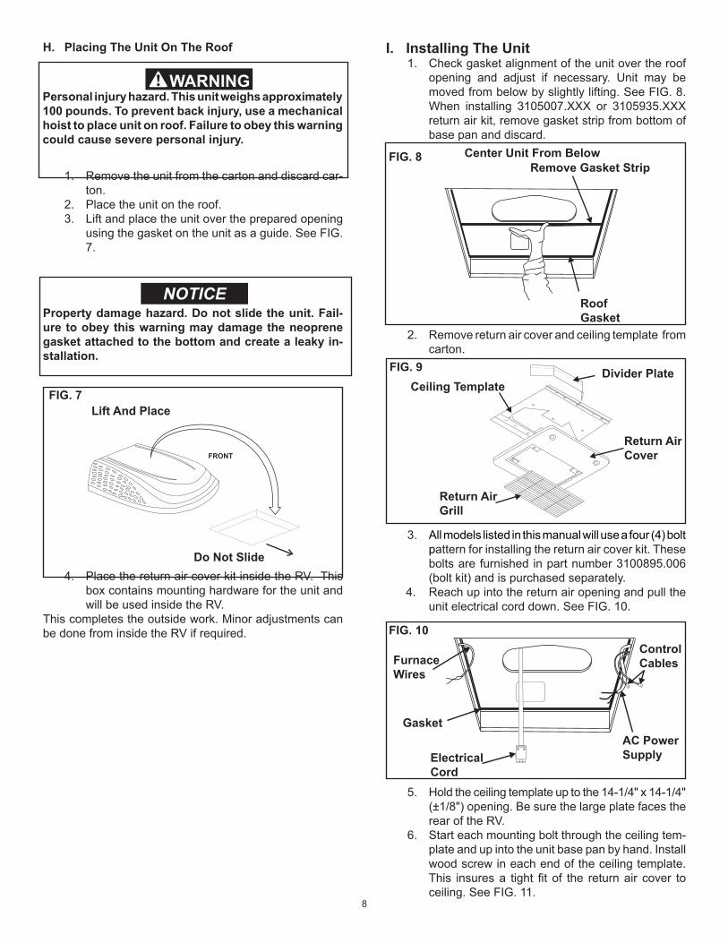
H. Placing The Unit On The Roof
1. Remove the unit from the carton and discard car-ton.
2. Place the unit on the roof. 3. Lift and place the unit over the prepared opening
using the gasket on the unit as a guide. See FIG. 7.
4. Place the return air cover kit inside the RV. This box contains mounting hardware for the unit and will be used inside the RV.
This completes the outside work. Minor adjustments can be done from inside the RV if required.
Personal injury hazard. This unit weighs approximately 100 pounds. To prevent back injury, use a mechanical hoist to place unit on roof. Failure to obey this warning could cause severe personal injury.
Property damage hazard. Do not slide the unit. Fail-ure to obey this warning may damage the neoprene gasket attached to the bottom and create a leaky in-stallation.
FIG. 7
FRONT
Lift And Place
Do Not Slide
I. Installing The Unit 1. Check gasket alignment of the unit over the roof
opening and adjust if necessary. Unit may be moved from below by slightly lifting. See FIG. 8. When installing 3105007.XXX or 3105935.XXX return air kit, remove gasket strip from bottom of base pan and discard.
2. Remove return air cover and ceiling template from carton.
3. All models listed in this manual will use a four (4) bolt pattern for installing the return air cover kit. These bolts are furnished in part number 3100895.006 (bolt kit) and is purchased separately.
4. Reach up into the return air opening and pull the unit electrical cord down. See FIG. 10.
5. Hold the ceiling template up to the 14-1/4" x 14-1/4" (±1/8") opening. Be sure the large plate faces the rear of the RV.
6. Start each mounting bolt through the ceiling tem-plate and up into the unit base pan by hand. Install wood screw in each end of the ceiling template. This insures a tight fit of the return air cover to ceiling. See FIG. 11.
Divider PlateCeiling Template
Return Air Cover
Return Air Grill
FIG. 9
FIG. 10
AC PowerSupply
ControlCablesFurnace
Wires
Gasket
ElectricalCord
FIG. 8 Center Unit From Below
RoofGasket
Remove Gasket Strip

9
Evenly tighten the four mounting bolts to a torque of 40 to 50 inch pounds. This will com-press the roof gasket approximately 1/2". The bolts are self locking so further tightening is not necessary. See FIG. 11.
7. Installation of Divider Plate a. Measure the ceiling to roof thickness: • If distance is 2.0" - 3-3/4", remove perfo-
rated tab from divider plate. • If distance is 3-3/4" - 5-1/2", remove no
tabs. b. Remove the backing paper from double sided
tape located on ceiling template. See FIG. 12.
If bolts are left loose there may not be an ad-equate roof seal or if over tightened, damage may occur to the unit base or ceiling template. Tighten to torque specifications listed in this manual.
c. Place divider plate up to bottom of the unit base pan firmly. The foam tape on the divider plate must seal to bottom of base pan. See FIG. 13.
Note: The adhesive on the insulation is extremely sticky. Be sure the part is located where desired before pressing into place. d. With slight pressure push the divider plate
against the double sided tape on the ceiling template.
e. Locate the 1/8" x 7" x 18" self -adhesive insula-tion supplied with the return air kit. Remove the backing paper from the insulation and carefully stick onto the ceiling template divider panel. See FIG. 14.
• Excess width is intended to seal the divider plate to the sides of the 14-1/4" x 14-1/4" (±1/8") opening. This is to help prevent cold air discharge from circulating into the unit return air opening.
• If the insulation is too high, stick excess height of insulation to the unit base pan. Do not cover up unit rating plate.
Improper installation and sealing of divider plate will cause the compressor to quick cycle on the cold control. This may result in fuse or circuit breaker opening and/or lack of cooling.
FIG. 11
Finger Tight
Front of Vehicle
Tighten To Com-press Gasket To 1/2"
Roof Gasket
Screws
FIG. 12 Backing Paper
2.00" -3.75"
FIG. 13
Push Divider Plate Firmly Onto Base Pan
FIG. 14Place Insulation In Position(Do Not Cover Unit Rating Plate) Foam Tape
Divider Plate
10
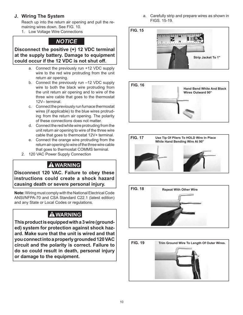
J. Wiring The System Reach up into the return air opening and pull the re-
maining wires down. See FIG. 10. 1. Low Voltage Wire Connections
a. Connect the previously run +12 VDC supply wire to the red wire protruding from the unit return air opening.
b. Connect the previously run –12 VDC supply wire to both the black wire protruding from the unit return air opening and to wire of the three wire cable that goes to the thermostat 12V– terminal.
c. Connect the previously run furnace thermostat wires (if applicable) to the blue wires protrud-ing from the return air opening. The polarity of these connections does not matter.
d. Connect the red/white wire protruding from the unit return air opening to wire of the three wire cable that goes to thermostat 12V+ terminal.
e. Connect the orange wire protruding from the return air opening to wire of the three wire cable that goes to thermostat COMMS terminal.
2. 120 VAC Power Supply Connection
Disconnect the positive (+) 12 VDC terminal at the supply battery. Damage to equipment could occur if the 12 VDC is not shut off.
Note: Wiring must comply with the National Electrical Code ANSI/NFPA-70 and CSA Standard C22.1 (latest edition) and any State or Local Codes or regulations.
FIG. 15
Strip Jacket To 1"
FIG. 16Hand Bend White And Black Wires Outward 90°
FIG. 17 Use Tip Of Pliers To HOLD Wire In PlaceWhile Hand Bending Wire At 90°
FIG. 18 Repeat With Other Wire
FIG. 19 Trim Ground Wire To Length Of Outer Wires.
a. Carefully strip and prepare wires as shown in FIGS. 15-19.
Disconnect 120 VAC. Failure to obey these instructions could create a shock hazard causing death or severe personal injury.
This product is equipped with a 3 wire (ground-ed) system for protection against shock haz-ard. Make sure that the unit is wired and that you connect into a properly grounded 120 VAC circuit and the polarity is correct. Failure to do so could result in death, personal injury or damage to the equipment.

11
b. Hold the clear strain relief cover with bottom facing upward as shown in FIG. 20.
Housing Assembly Hinge Slots
HingePosts
Wires Trimmed AndCorrectly Located InLocator Stops
Strain ReliefCover
FIG. 21
Attaching Housing Assembly To Strain Relief Cover With Tongue And Groove Pliers, Squeeze Squarely & Firmly Between Ribs A AND B
Strain Relief Cover
LockingLatch
RIB A RIB BLockingRamp
Housing Assembly
10"Minimum
FIG. 22
HousingAssembly
Strain ReliefCover
Strain ReliefCover
“Hermaphroditic” PartMates With Itself
Depress Mating LatchTo Disconnect
HousingAssemblyDepress Mating
Latch To Disconnect
To release the connector system, depress both mating latches at the same time and pull the connectors apart. To reconnect, simply re-mate the connectors and slide them together until mating latches lock.
FIG. 23
c. Lay wire into locator slots, making sure the black wire is placed into the polarization slot as shown in FIG. 20.
d. Press the cable sheath into the integral strain relief slot as shown in FIG. 20. Trimming of ground wire and possibly others will be nec-essary. Wires must not extend beyond the locators as shown in FIG. 21.
g. Inspect the connector to ensure the wires have been properly engaged into the hous-ing assembly contacts. A properly terminated wire is fully seated into its proper slots with no significant bow of the cover. If the wires ex-tend past the insulation stops, the wires must be re-terminated with a NEW CONNECTOR. Once the cover has been closed the connec-tor cannot be re-used. Failure to comply with this procedure may result in the failure of the connector.
h. Mating and un-mating the completed connec-tor is illustrated in FIG. 23.
FIG. 20 Load Cable Into Strain Relief
Wire Locator Slots
Position Black Wire Into Locator Slot
StrainReliefFingers
Strain Relief Cover(Bottom Facing Upward)
Roll Cable Sheath IntoIntegral Strain Relief
e. While holding the strain relief cover, position the housing’s hinge posts into the hinge slots and press down until both lock into place as shown in FIG. 21.
f. Close the strain relief cover and housing by hand. Squeeze the top and bottom closed with tongue and groove pliers as shown in FIG. 22. Pliers must be a minimum of 10" long. Squeeze firmly on both sides, squarely across the connector between ribs A and B to ensure wires seat completely into slots.

12
FIG. 24 Return Air Cover
Hole Plugs Return
Air Grill
6. This completes the unit installation.
L. General Information 1. Frost Formation On Cooling Coil
Frost on a small portion of the coil is not un usual Under certain conditions, ice may form on the evaporator coil. This is indicated by very cold out-put at very low air speed and the icing can be seen through the air inlet hole with the filter removed. If this should occur, inspect the filter and clean if dirty. Make sure air vents are open and not obstructed. Units have a greater tendency to frost when the outside temperature is relatively low. This may be prevented by ad justing the thermostat control knob to a warmer setting (counter clockwise). Should frosting con tinue, operate on any FAN ONLY setting until the cooling coil is free of frost; then resume nor mal operation. If frost condition persist, contact your local service center for assistance.
2. Heat GainThe ability of this air conditioner to maintainthe desired inside temperature depends on the heat gain of the RV. Some preventative measures taken by the occupants of the RV can reduce the heat gain and improve the performance of the air conditioner. During extremely high outdoor tem peratures, the heat gain of the RV can may be reduced by: a. Parking the RV in a shaded area b. Using window shades (blinds and/or curtains) c. Keeping windows and doors shut or minimizing usaged. Avoid the use of heat producing appliances
K. Installing Decorative Inside Cover 1. Remove the return air grill from the return air cov-
er. 2. Place the return air cover up to the ceiling tem-
plate. 3. Install cover to template with #8 x 3/8" blunt point
Phillips head screws provided (6 required). 4. Reinstall filter return air grill into return air cover.
Align tabs with mating notches and snap into place.
5. Install two hole plugs into screw holes in back of return air cover. See FIG. 24.
Operation on High Fan/Cooling mode will give optimum or maximum efficiency in high humidity or high outside temperatures. Starting the air con-ditioner early in the morning and giving it a “head start” on the expected high outdoor ambient will greatly improve its ability to maintain the desired indoor temperature. For a more permanent solution to high heat gain, acces sories like Dometic outdoor patio and window awnings will reduce heat gain by removing the direct sun. They also add a nice area to enjoy company during the cool of the evening.
3. CondensationThe manufacturer of this unit will not be responsi-ble for damage caused by condensation forming on ceilings, windows, or other surfaces. Air contains water vapor which condenses when temperature of a surface is below Dew point. During normal operation this unit is designed to remove a certain amount of moisture from the air, depend ing on the size of the space being conditioned. Keeping doors and windows closed when this air conditioner is in operation will greatly reduce the chance of con-densation forming on interior surfaces.
4. Air DistributionEach A/C unit operating in cool mode, must have a minimum of 2 distribution vents, or the quick cool vent and one vent open, to avoid the risk of freezing coils and improper function.

13
WIRING DIAGRAM
541915A & 541916A Wiring Diagram
COM
3313500.021
PTCR(OPT)
BR
WHT
WHT
BR
STARTCAP
RED
WHT
BLU
RED
OLC
R S
YL}
SOLAR ORDIRTY FILTERINDICATOR IF USED
MOTOR
NO
Y8
Y5
Y10
BLU
BLK
RED
Y9
FREEZE SENSORJ5
115 VAC,
USE COPPER60 HZ, 1 ɸ
CONDUCTORSONLY
GRN/YEL (EARTH)WHT (NEUT)
BLK (LINE)
TSTAT) (TO 12V +
BLU
BLU
Y3
Y4
12
43
12V -COMMORG
BLK
REDRED/WHT
12V +
FURNACE
FURNACE
+-
}12V
SUPPLY
TSTATTOJ2
FACTORY WIRINGFIELD WIRING
BLK
PASSED DIELECTRIC
K1 RELAY
Related Documents


