DA 40 AFM Introduction Rev. No. Reason Chapter Page(s) Date of Revision EASA Approv- al No. ACG Compliance Date Inserted Signature Doc. # 6.01.01-E Rev. 9 % 31-Jan-2014 % Page 0 - 5 8 MÄM-40- -176, -227/a, -313, -344, -360/a, -378, -401, -415, -428, -446; OÄM-40- -217, -251, -253/b, 258, -267, -277/a, -279, 283/a, -284, -289, -326, -327; corrections all all except cover page 01 Dec 2010 Revision No. 8 of the AFM Doc. No. 6.01.01-E is approved under the authority of DOA No. EASA.21J.052 % 9 % MÄM 40- % -580, -617, % OÄM 40- % -252, -362, % -369, -371 % 0, 1, 2, % 3, 4A, 6, % 7 % 0-5, 0-6, 0-7, 0-8, % 0-9, 0-11, 0-12, % 0-13, 1-3, 1-7, 2-22, % 2-25, 3-29, 4A-11, % 4A-12, 4A-22 thru % 4A-24, 4A-34, % 4A-35, 6-17 thru % 6-34, 7-1, 7.2, 7-15 % thru 7-58 % 31 Jan 2014 % Revision No. 9 % of the AFM % Doc. No. % 6.01.01-E is % approved % under the % authority of % DOA No. % EASA.21J.052 % % %

Welcome message from author
This document is posted to help you gain knowledge. Please leave a comment to let me know what you think about it! Share it to your friends and learn new things together.
Transcript

DA 40 AFM Introduction
Rev.No.
Reason Chapter Page(s)Date of
RevisionEASA Approv-
al No.ACG
ComplianceDate
InsertedSignature
Doc. # 6.01.01-E Rev. 9% 31-Jan-2014% Page 0 - 5
8
MÄM-40-
-176, -227/a,
-313, -344,
-360/a, -378,
-401, -415,
-428, -446;
OÄM-40-
-217, -251,
-253/b, 258,
-267, -277/a,
-279, 283/a,
-284, -289,
-326, -327;
corrections
allall except cover
page01 Dec 2010
Revision No. 8
of the AFM
Doc. No.
6.01.01-E is
approved
under the
authority of
DOA No.
EASA.21J.052
%%%
9%
MÄM 40-%-580, -617,%OÄM 40-%
-252, -362, %-369, -371%
0, 1, 2,%3, 4A, 6,%
7%
0-5, 0-6, 0-7, 0-8, %0-9, 0-11, 0-12, %
0-13, 1-3, 1-7, 2-22,%2-25, 3-29, 4A-11,%4A-12, 4A-22 thru%
4A-24, 4A-34, %4A-35, 6-17 thru %
6-34, 7-1, 7.2, 7-15%thru 7-58%
31 Jan 2014%
Revision No. 9%of the AFM%Doc. No.%
6.01.01-E is%approved%under the%
authority of%DOA No.%
EASA.21J.052%
%%%
%%%%%%%%%
Introduction DA 40 AFM
Page 0 - 6 Rev. 9% 31-Jan-2014% Doc. # 6.01.01-E
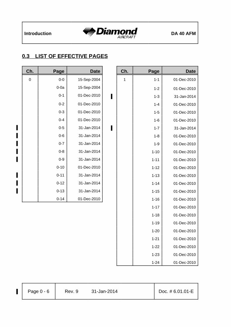
0.3 LIST OF EFFECTIVE PAGES
Ch. Page Date
0 0-0 15-Sep-2004
0-0a 15-Sep-2004
0-1 01-Dec-2010
0-2 01-Dec-2010
0-3 01-Dec-2010
0-4 01-Dec-2010
0-5 31-Jan-2014%
0-6 31-Jan-2014%
0-7 31-Jan-2014%
0-8 31-Jan-2014%
0-9 31-Jan-2014%
0-10 01-Dec-2010
0-11 31-Jan-2014%
0-12 31-Jan-2014%
0-13 31-Jan-2014%
0-14 01-Dec-2010
Ch. Page Date
1 1-1 01-Dec-2010
1-2 01-Dec-2010
1-3 31-Jan-2014%
1-4 01-Dec-2010
1-5 01-Dec-2010
1-6 01-Dec-2010
1-7 31-Jan-2014%
1-8 01-Dec-2010
1-9 01-Dec-2010
1-10 01-Dec-2010
1-11 01-Dec-2010
1-12 01-Dec-2010
1-13 01-Dec-2010
1-14 01-Dec-2010
1-15 01-Dec-2010
1-16 01-Dec-2010
1-17 01-Dec-2010
1-18 01-Dec-2010
1-19 01-Dec-2010
1-20 01-Dec-2010
1-21 01-Dec-2010
1-22 01-Dec-2010
1-23 01-Dec-2010
1-24 01-Dec-2010

DA 40 AFM Introduction
Doc. # 6.01.01-E Rev. 9% 31-Jan-2014% Page 0 - 7
Ch. Page Date
2 appr. 2-1 01-Dec-2010
appr. 2-2 01-Dec-2010
appr. 2-3 01-Dec-2010
appr. 2-4 01-Dec-2010
appr. 2-5 01-Dec-2010
appr. 2-6 01-Dec-2010
appr. 2-7 01-Dec-2010
appr. 2-8 01-Dec-2010
appr. 2-9 01-Dec-2010
appr. 2-10 01-Dec-2010
appr. 2-11 01-Dec-2010
appr. 2-12 01-Dec-2010
appr. 2-13 01-Dec-2010
appr. 2-14 01-Dec-2010
appr. 2-15 01-Dec-2010
appr. 2-16 01-Dec-2010
appr. 2-17 01-Dec-2010
appr. 2-18 01-Dec-2010
appr. 2-19 01-Dec-2010
appr. 2-20 01-Dec-2010
appr. 2-21 01-Dec-2010
appr. 2-22 31-Jan-2014%
appr. 2-23 01-Dec-2010
appr. 2-24 01-Dec-2010
appr. 2-25 31-Jan-2014%
appr. 2-26 01-Dec-2010
appr. 2-27 01-Dec-2010
Ch. Page Date
2 appr. 2-28 01-Dec-2010
appr. 2-29 01-Dec-2010
appr. 2-30 01-Dec-2010
appr. 2-31 01-Dec-2010
appr. 2-32 01-Dec-2010
appr. 2-33 01-Dec-2010
appr. 2-34 01-Dec-2010

Introduction DA 40 AFM
Page 0 - 8 Rev. 9% 31-Jan-2014% Doc. # 6.01.01-E
Ch. Page Date
3 3-1 01-Dec-2010
3-2 01-Dec-2010
3-3 01-Dec-2010
3-4 01-Dec-2010
3-5 01-Dec-2010
3-6 01-Dec-2010
3-7 01-Dec-2010
3-8 01-Dec-2010
3-9 01-Dec-2010
3-10 01-Dec-2010
3-11 01-Dec-2010
3-12 01-Dec-2010
3-13 01-Dec-2010
3-14 01-Dec-2010
3-15 01-Dec-2010
3-16 01-Dec-2010
3-17 01-Dec-2010
3-18 01-Dec-2010
3-19 01-Dec-2010
3-20 01-Dec-2010
3-21 01-Dec-2010
3-22 01-Dec-2010
3-23 01-Dec-2010
3-24 01-Dec-2010
3-25 01-Dec-2010
3-26 01-Dec-2010
3-27 01-Dec-2010
3-28 01-Dec-2010
Ch. Page Date
3 3-29 31-Jan-2014%
3-30 31-Jan-2014%
3-31 01-Dec-2010
3-32 01-Dec-2010
3-33 01-Dec-2010
3-34 01-Dec-2010
3-35 01-Dec-2010
3-36 01-Dec-2010
3-37 01-Dec-2010
3-38 01-Dec-2010
3-39 01-Dec-2010
3-40 01-Dec-2010
3-41 01-Dec-2010
3-42 01-Dec-2010

DA 40 AFM Introduction
Doc. # 6.01.01-E Rev. 9% 31-Jan-2014% Page 0 - 9
Ch. Page Date
4A 4A-1 01-Dec-2010
4A-2 01-Dec-2010
4A-3 01-Dec-2010
4A-4 01-Dec-2010
4A-5 01-Dec-2010
4A-6 01-Dec-2010
4A-7 01-Dec-2010
4A-8 01-Dec-2010
4A-9 01-Dec-2010
4A-10 01-Dec-2010
4A-11 31-Jan-2014%
4A-12 31-Jan-2014%
4A-13 01-Dec-2010
4A-14 01-Dec-2010
4A-15 01-Dec-2010
4A-16 01-Dec-2010
4A-17 01-Dec-2010
4A-18 01-Dec-2010
4A-19 01-Dec-2010
4A-20 01-Dec-2010
4A-21 01-Dec-2010
4A-22 31-Jan-2014%
4A-23 31-Jan-2014%
4A-24 31-Jan-2014%
4A-25 01-Dec-2010
4A-26 01-Dec-2010
4A-27 01-Dec-2010
Ch. Page Date
4A 4A-28 01-Dec-2010
4A-29 01-Dec-2010
4A-30 01-Dec-2010
4A-31 01-Dec-2010
4A-32 01-Dec-2010
4A-33 01-Dec-2010
4A-34 31-Jan-2014%
4A-35 31-Jan-2014%
4A-36 01-Dec-2010
4A-37 01-Dec-2010
4A-38 01-Dec-2010
4A-39 01-Dec-2010
4A-40 01-Dec-2010

Introduction DA 40 AFM
Page 0 - 10 Revision 8 01-Dec-2010 Doc. # 6.01.01-E
Ch. Page Date
4B 4B-1 01-Dec-2010
4B-2 01-Dec-2010
4B-3 01-Dec-2010
4B-4 01-Dec-2010
4B-5 01-Dec-2010
4B-6 01-Dec-2010
4B-7 01-Dec-2010
4B-8 01-Dec-2010
4B-9 01-Dec-2010
4B-10 01-Dec-2010
4B-11 01-Dec-2010
4B-12 01-Dec-2010
Ch. Page Date
5 5-1 01-Dec-2010
5-2 01-Dec-2010
5-3 01-Dec-2010
5-4 01-Dec-2010
5-5 01-Dec-2010
5-6 01-Dec-2010
5-7 01-Dec-2010
5-8 01-Dec-2010
5-9 01-Dec-2010
5-10 01-Dec-2010
5-11 01-Dec-2010
5-12 01-Dec-2010
5-13 01-Dec-2010
5-14 01-Dec-2010
5-15 01-Dec-2010
5-16 01-Dec-2010
5-17 01-Dec-2010
5-18 01-Dec-2010
5-19 01-Dec-2010
5-20 01-Dec-2010
5-21 01-Dec-2010
5-22 01-Dec-2010
5-23 01-Dec-2010
5-24 01-Dec-2010

DA 40 AFM Introduction
Doc. # 6.01.01-E Rev. 9% 31-Jan-2014% Page 0 - 11
Ch. Page Date
6 6-1 01-Dec-2010
6-2 01-Dec-2010
6-3 01-Dec-2010
6-4 01-Dec-2010
6-5 01-Dec-2010
6-6 01-Dec-2010
6-7 01-Dec-2010
6-8 01-Dec-2010
6-9 01-Dec-2010
6-10 01-Dec-2010
6-11 01-Dec-2010
6-12 01-Dec-2010
6-13 01-Dec-2010
6-14 01-Dec-2010
6-15 01-Dec-2010
6-16 01-Dec-2010
6-17 31-Jan-2014%
6-18 31-Jan-2014%
6-19 31-Jan-2014%
6-20 31-Jan-2014%
6-21 31-Jan-2014%
6-22 31-Jan-2014%
6-23 31-Jan-2014%
6-24 31-Jan-2014%
6-25 31-Jan-2014%
6-26 31-Jan-2014%
6-27 31-Jan-2014%
Ch. Page Date
6 6-28 31-Jan-2014%
6-29 31-Jan-2014%
6-30 31-Jan-2014%
6-31 31-Jan-2014%
6-32 31-Jan-2014%
6-33% 31-Jan-2014%
6-34% 31-Jan-2014%

Introduction DA 40 AFM
Page 0 - 12 Rev. 9% 31-Jan-2014% Doc. # 6.01.01-E
Ch. Page Date
7 7-1 31-Jan-2014%
7-2 31-Jan-2014%
7-3 01-Dec-2010
7-4 01-Dec-2010
7-5 01-Dec-2010
7-6 01-Dec-2010
7-7 01-Dec-2010
7-8 01-Dec-2010
7-9 01-Dec-2010
7-10 01-Dec-2010
7-11 01-Dec-2010
7-12 01-Dec-2010
7-13 01-Dec-2010
7-14 01-Dec-2010
7-15 31-Jan-2014%
7-16 31-Jan-2014%
7-17 31-Jan-2014%
7-18 31-Jan-2014%
7-19 31-Jan-2014%
7-20 31-Jan-2014%
7-21 31-Jan-2014%
7-22 31-Jan-2014%
7-23 31-Jan-2014%
7-24 31-Jan-2014%
7-25 31-Jan-2014%
7-26 31-Jan-2014%
7-27 31-Jan-2014%
Ch. Page Date
7 7-28 31-Jan-2014%
7-29 31-Jan-2014%
7-30 31-Jan-2014%
7-31 31-Jan-2014%
7-32 31-Jan-2014%
7-33 31-Jan-2014%
7-34 31-Jan-2014%
7-35 31-Jan-2014%
7-36 31-Jan-2014%
7-37 31-Jan-2014%
7-38 31-Jan-2014%
7-39 31-Jan-2014%
7-40 31-Jan-2014%
7-41 31-Jan-2014%
7-42 31-Jan-2014%
7-43 31-Jan-2014%
7-44 31-Jan-2014%
7-45 31-Jan-2014%
7-46 31-Jan-2014%
7-47 31-Jan-2014%
7-48 31-Jan-2014%
7-49 31-Jan-2014%
7-50 31-Jan-2014%
7-51 31-Jan-2014%
7-52 31-Jan-2014%
7-53 31-Jan-2014%
7-54 31-Jan-2014%

DA 40 AFM Introduction
Doc. # 6.01.01-E Rev. 9% 31-Jan-2014% Page 0 - 13
Ch. Page Date
7 7-55 31-Jan-2014%
7-56 31-Jan-2014%
7-57 31-Jan-2014%
7-58 31-Jan-2014%
Ch. Page Date
8 8-1 01-Dec-2010
8-2 01-Dec-2010
8-3 01-Dec-2010
8-4 01-Dec-2010
8-5 01-Dec-2010
8-6 01-Dec-2010
8-7 01-Dec-2010
8-8 01-Dec-2010
8-9 01-Dec-2010
8-10 01-Dec-2010
8-11 01-Dec-2010
8-12 01-Dec-2010
Ch. Page Date
9 9-1 01-Dec-2010
9-2 01-Dec-2010
9-3 01-Dec-2010
9-4 01-Dec-2010
9-5 01-Dec-2010
9-6 01-Dec-2010

Introduction DA 40 AFM
Page 0 - 14 Rev. 8 01-Dec-2010 Doc. # 6.01.01-E
0.4 TABLE OF CONTENTS
Chapter
GENERAL
(a non-approved chapter) . . . . . . . . . . . . . . . . . . . . . . . . . . . . . . . . . . . . . . . 1
OPERATING LIMITATIONS
(an approved chapter) . . . . . . . . . . . . . . . . . . . . . . . . . . . . . . . . . . . . . . . . . . 2
EMERGENCY PROCEDURES
(a non-approved chapter) . . . . . . . . . . . . . . . . . . . . . . . . . . . . . . . . . . . . . . . 3
NORMAL OPERATING PROCEDURES
(a non-approved chapter) . . . . . . . . . . . . . . . . . . . . . . . . . . . . . . . . . . . . . . 4A
ABNORMAL OPERATING PROCEDURES
(a non-approved chapter) . . . . . . . . . . . . . . . . . . . . . . . . . . . . . . . . . . . . . . 4B
PERFORMANCE
(a non-approved chapter) . . . . . . . . . . . . . . . . . . . . . . . . . . . . . . . . . . . . . . . 5
MASS AND BALANCE / EQUIPMENT LIST
(a non-approved chapter) . . . . . . . . . . . . . . . . . . . . . . . . . . . . . . . . . . . . . . . 6
DESCRIPTION OF THE AIRPLANE AND ITS SYSTEMS
(a non-approved chapter) . . . . . . . . . . . . . . . . . . . . . . . . . . . . . . . . . . . . . . . 7
AIRPLANE HANDLING, CARE AND MAINTENANCE
(a non-approved chapter) . . . . . . . . . . . . . . . . . . . . . . . . . . . . . . . . . . . . . . . 8
SUPPLEMENTS . . . . . . . . . . . . . . . . . . . . . . . . . . . . . . . . . . . . . . . . . . . . . . . . . . . . 9
DA 40 AFM General
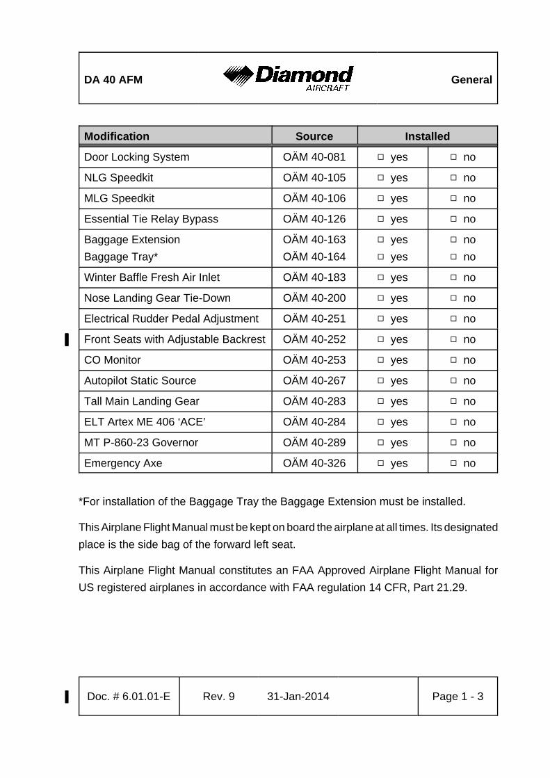
Modification Source Installed
Doc. # 6.01.01-E Rev. 9% 31-Jan-2014% Page 1 - 3
Door Locking System OÄM 40-081 9 yes 9 no
NLG Speedkit OÄM 40-105 9 yes 9 no
MLG Speedkit OÄM 40-106 9 yes 9 no
Essential Tie Relay Bypass OÄM 40-126 9 yes 9 no
Baggage Extension
Baggage Tray*
OÄM 40-163
OÄM 40-164
9 yes
9 yes
9 no
9 no
Winter Baffle Fresh Air Inlet OÄM 40-183 9 yes 9 no
Nose Landing Gear Tie-Down OÄM 40-200 9 yes 9 no
Electrical Rudder Pedal Adjustment OÄM 40-251 9 yes 9 no
Front Seats with Adjustable Backrest% OÄM 40-252% 9 yes% 9 no%
CO Monitor OÄM 40-253 9 yes 9 no
Autopilot Static Source OÄM 40-267 9 yes 9 no
Tall Main Landing Gear OÄM 40-283 9 yes 9 no
ELT Artex ME 406 ‘ACE’ OÄM 40-284 9 yes 9 no
MT P-860-23 Governor OÄM 40-289 9 yes 9 no
Emergency Axe OÄM 40-326 9 yes 9 no
*For installation of the Baggage Tray the Baggage Extension must be installed.
This Airplane Flight Manual must be kept on board the airplane at all times. Its designated
place is the side bag of the forward left seat.
This Airplane Flight Manual constitutes an FAA Approved Airplane Flight Manual for
US registered airplanes in accordance with FAA regulation 14 CFR, Part 21.29.
General DA 40 AFM
Page 1 - 4 Rev. 8 01-Dec-2010 Doc. # 6.01.01-E
CAUTION
The DA 40 is a single engine airplane. When the operating
limitations and maintenance requirements are complied with,
it has the high degree of reliability which is required by the
certification basis. Nevertheless, an engine failure is not
completely impossible. For this reason, flights during the
night, on top, under instrument meteorological conditions
(IMC), or above terrain which is unsuitable for a landing,
constitute a risk. It is therefore highly recommended to select
flight times and flight routes such that this risk is minimized.

DA 40 AFM General
Doc. # 6.01.01-E Rev. 9% 31-Jan-2014% Page 1 - 7
Vertical Tail
Area : appr. 1.60 m² appr. 17.2 sq.ft.
Rudder area : appr. 0.47 m² appr. 5.1 sq.ft.
Landing Gear
Track : appr. 2.97 m appr. 9 ft 9 in
Wheelbase : appr. 1.68 m appr. 5 ft 6 in
Nose wheel : 5.00-5; 6 PR, 120 mph
Main wheel : (a) 6.00-6; 6 PR, 120 mph in combination with any
MLG strut
(b) 6.00-6; 8 PR, 120 mph in combination with any%
MLG strut%
(c) 15 x 6.0-6; 6 PR, 160 mph%
(OÄM 40-124; only in combination with the %
“thin”/”18 mm” [MÄM 40-123] or the “tall”%
[OÄM 40-283] MLG strut)%

General DA 40 AFM
Page 1 - 8 Rev. 8 01-Dec-2010 Doc. # 6.01.01-E
1.5 DEFINITIONS AND ABBREVIATIONS
(a) Airspeeds
CAS: Calibrated Airspeed. Indicated airspeed, corrected for installation and
instrument errors. CAS equals TAS at standard atmospheric conditions at MSL.
IAS: Indicated Airspeed as shown on an airspeed indicator.
KCAS: CAS in knots.
KIAS: IAS in knots.
TAS: True Airspeed. The speed of the airplane relative to the air. TAS is CAS
corrected for errors due to altitude and temperature.
vA: Maneuvering Speed. Full or abrupt control surface movement is not permissible
above this speed.
vFE: Max. Flaps Extended Speed. This speed must not be exceeded with the given
flap setting.
vNE: Never Exceed Speed in smooth air. This speed must not be exceeded in any
operation.
vNO Maximum Structural Cruising Speed. This speed may be exceeded only in
smooth air, and then only with caution.
vS: Stalling Speed, or the minimum continuous speed at which the airplane is still
controllable in the given configuration.
vS0: Stalling Speed, or the minimum continuous speed at which the airplane is still
controllable in the landing configuration.
vx: Best Angle-of-Climb Speed.
vy: Best Rate-of-Climb Speed.

DA 40 AFMOperating
Limitations
Doc. # 6.01.01-E Rev. 8 01-Dec-2010EASA
approvedPage 2 - 21
NOTE
A list of approved equipment can be found in Chapter 6.
NOTE
For the upgrade of an airplane for Night VFR or IFR operation
it is not sufficient to install the required equipment. The retrofit
must be carried out in accordance with the requirements of
the manufacturer (see Service Bulletins) and the national
Airworthiness Authority. Any additional equipment (equipment
which is not listed in the Equipment List in Section 6.5) must
also be approved for the intended kind of operation by the
national Airworthiness Authority.

Operating
LimitationsDA 40 AFM
Page 2 - 22 Rev. 9' 31-Jan-2014'EASA
approvedDoc. # 6.01.01-E
2.14 FUEL
Fuel Grade AVGAS 100LL / AVGAS 100/130LL (ASTM D910)'
AVGAS 100 / AVGAS 100/130 (ASTM D910)'
Fuel Quantity
a) Standard Tank:
Total fuel quantity : 2 x 20.6 US gal (app. 2 x 78 liter)
Unusable fuel : 2 x 0.5 US gal (app. 2 x 2 liter)
Max. indicated fuel quantity:
up to and incl. serial no. 40.054 : 15 US gal (app. 57 liter) per tank
serial no. 40.055 & subsequent : 17 US gal (app. 64 liter) per tank
Max. permissible difference
between right and left tank : 10 US gal (app. 38 liter)

DA 40 AFMOperating
Limitations
Doc. # 6.01.01-E Rev. 9' 31-Jan-2014'EASA
approvedPage 2 - 25
AVGAS 100LL
76 l / 20 US gal.
AVGAS 100LL
94 l / 25 US gal.
If MÄM 40-227 is carried out:
Maneuvering Speed:
vA = 111 KIAS (above 1036 up to 1200 kg, above 2284 up to 2646 lb)
vA = 94 KIAS (780 to 1036 kg, 1720 to 2284 lb)
The airplane may only be operated in accordance with the Airplane
Flight Manual. It can be operated in the „Normal“ and the „Utility“
categories in non-icing conditions. Provided that national operational
requirements are met and the appropriate equipment is installed, this
airplane is approved for the following kinds of operation: day VFR,
night VFR and IFR. All aerobatic maneuvers including spinning are
prohibited.
For further operational limitations refer to the Airplane Flight Manual.
No smoking.
Next to Each of the Two Fuel Filler Necks:
a) Standard Tank:'
If MÄM 40-617 is installed:'
'
'
'
'
b) Long Range Tank (if installed):'
If MÄM 40-617 is installed:'
'
'
'
'

Operating
LimitationsDA 40 AFM
Page 2 - 26 Rev. 8 01-Dec-2010EASA
approvedDoc. # 6.01.01-E
max. indicated fuel quantity: 15 US gal
left and right tank max. 10 US gal difference
For use of max. tank capacity see AFM
max. indicated fuel quantity: 17 US galleft and right tank max. 10 US gal difference
For use of max. tank capacity see AFM
Fuel qty. indication: 16 + 9 US gal
max. difference LH/RH tank: 8 US gal
AUX FUEL QTY switch for LH/RH auxiliary fuel quantity
NOTE: See AFM for more information on AUX FUEL
Next to the Fuel Quantity Indication:
a) Standard Tank:
Up to serial number 40.054:
Serial number 40.055 and subsequent:
b) Long Range Tank (if installed):

DA 40 AFMEmergency
Procedures
Doc. # 6.01.01-E Rev. 9% 31-Jan-2014% Page 3 - 29
3.5 EMERGENCY LANDINGS
3.5.1 EMERGENCY LANDING WITH ENGINE OFF
CAUTION%
For emergency landing the adjustable backrests (if installed)%
must be fixed in the upright position. %
1. Adjustable backrests (if installed) . . . . . . . . adjust to the upright position%
described by a placard on%
the roll-over bar and verify%
proper fixation.%
2. Select suitable landing area. If no level landing area is available, a landing%
on an upward slope should be sought.
3. Consider wind.%
4. Approach: If possible, fly along a short-cut rectangular circuit. On the%
downwind leg of the circuit the landing area should be
inspected for obstacles from a suitable height. The degree of
offset at each part of the circuit will allow the wind speed and
direction to be assessed.
5. Airspeed . . . . . . . . . . . . . . . . . . . . . . . . . . . 76 KIAS (1200 kg, 2646 lb)%
73 KIAS (1150 kg, 2535 lb)
68 KIAS (1000 kg, 2205 lb)
60 KIAS (850 kg, 1874 lb)
6. If time allows . . . . . . . . . . . . . . . . . . . . . . . . advise ATC%
7. Fuel tank selector . . . . . . . . . . . . . . . . . . . . OFF%
CONTINUED

Emergency
ProceduresDA 40 AFM
Page 3 - 30 Rev. 9% 31-Jan-2014% Doc. # 6.01.01-E
When It Is Certain That the Landing Field Will Be Reached:
8. Flaps . . . . . . . . . . . . . . . . . . . . . . . . . . . . . . LDG%
9. Safety harnesses . . . . . . . . . . . . . . . . . . . . . tighten%
CAUTION
If sufficient time is remaining, the risk of fire in the event of
a collision with obstacles can be reduced as follows:
- Ignition switch . . . . . . . . . . . . . . . . OFF
- Master switch (ALT/BAT) . . . . . . . OFF
10. Touchdown with the lowest possible airspeed%
END OF CHECKLIST

DA 40 AFMNormal Operating
Procedures
Doc. # 6.01.01-E Rev. 9% 31-Jan-2014% Page 4A - 11
4A.3.2 BEFORE STARTING ENGINE
CAUTION%
For take-off the adjustable backrests (if installed) must be%
fixed in the upright position.%
NOTE%
The pilot must ensure that a passenger sitting on a front seat%
is instructed in the operation of the adjustable backrest (if%
installed).%
1. Pre-flight inspection . . . . . . . . . . . . . . . . . . . complete
2. Rudder pedals . . . . . . . . . . . . . . . . . . . . . . . adjusted
3. Passengers . . . . . . . . . . . . . . . . . . . . . . . . . instructed%
4. Adjustable backrests (if installed) . . . . . . . . adjust to the upright position%
described by a placard on%
the roll-over bar and verify%
proper fixation.%
5. Safety harnesses . . . . . . . . . . . . . . . . . . . . . all on and fastened%
6. Baggage . . . . . . . . . . . . . . . . . . . . . . . . . . . check, secured%
7. Rear door . . . . . . . . . . . . . . . . . . . . . . . . . . closed and locked%
8. Door lock (if installed) . . . . . . . . . . . . . . . . . unblocked, key removed%
CAUTION
When operating the canopy, ensure that there are no
obstructions between the canopy and the mating frame, for
example seat belts, clothing, etc. When operating the locking
handle do NOT apply undue force.
A slight downward pressure on the canopy may be required
to ease handle operation.CONTINUED

Normal Operating
ProceduresDA 40 AFM
Page 4A - 12 Rev. 9% 31-Jan-2014% Doc. # 6.01.01-E
9. Front canopy . . . . . . . . . . . . . . . . . . . . . . . . Position 1 or 2 (“Cooling%
Gap”)
10. Canopy lock (if installed) . . . . . . . . . . . . . . . unblocked, key removed%
11. Parking brake . . . . . . . . . . . . . . . . . . . . . . . . set%
12. Flight controls . . . . . . . . . . . . . . . . . . . . . . . free movement%
13. Trim wheel . . . . . . . . . . . . . . . . . . . . . . . . . . T/O%
14. Throttle . . . . . . . . . . . . . . . . . . . . . . . . . . . . . IDLE%
15. RPM lever . . . . . . . . . . . . . . . . . . . . . . . . . . HIGH RPM%
16. Mixture control lever . . . . . . . . . . . . . . . . . . LEAN%
17. Friction device, throttle quadrant . . . . . . . . . adjusted%
18. Alternate air . . . . . . . . . . . . . . . . . . . . . . . . . CLOSED%
19. Alternate static valve . . . . . . . . . . . . . . . . . . CLOSED, if installed%
20. Avionics Master switch . . . . . . . . . . . . . . . . . OFF%
21. Essential Bus switch . . . . . . . . . . . . . . . . . . OFF, if installed%
CAUTION
When the essential bus is switched ON, the battery will not
be charged unless the essential tie relay bypass
(OÄM 40-126) is installed.
22. Master switch (BAT) . . . . . . . . . . . . . . . . . . ON%
23. Annunciator panel . . . . . . . . . . . . . . . . . . . . test (see Section 7.11)%
24. Fuel tank selector . . . . . . . . . . . . . . . . . . . . on full tank%
WARNING
Never move the propeller by hand while the ignition is
switched on, as it may result in serious personal injury.
Never try to start the engine by hand.
END OF CHECKLIST

DA 40 AFMNormal Operating
Procedures
Doc. # 6.01.01-E Rev. 9% 31-Jan-2014% Page 4A - 21
Remedy:
1. For about 1 to 2 minutes, or until the engine settles,
run at a speed of 1800 to 2000 RPM. Oil and cylinder
head temperatures must stay within limits.
2. Pull throttle back to IDLE to confirm smooth running.
3. Set throttle to 1200 RPM and mixture for taxiing, i.e.,
use mixture control lever to set the maximum RPM
attainable.
4. Immediately before the take-off run set the mixture for
take-off, apply full throttle and hold this position for
10 seconds.
NOTE
Vapor lock can be avoided if the engine is run at speeds of
1800 RPM or more. This results in lower fuel temperatures.
END OF CHECKLIST

Normal Operating
ProceduresDA 40 AFM
Page 4A - 22 Rev. 9% 31-Jan-2014% Doc. # 6.01.01-E
4A.3.6 BEFORE TAKE-OFF
CAUTION
Before take-off, the engine must run on each tank for at least
1 minute at 1500 RPM.
CAUTION%
For take-off the adjustable backrests (if installed) must be%
fixed in the upright position.%
1. Position airplane into wind if possible
2. Parking brake . . . . . . . . . . . . . . . . . . . . . . . . set
3. Adjustable backrests (if installed) . . . . . . . . verify upright position%
And proper fixation%
4. Safety harnesses . . . . . . . . . . . . . . . . . . . . . on and fastened%
5. Rear door . . . . . . . . . . . . . . . . . . . . . . . . . . . check closed and locked%
6. Front canopy . . . . . . . . . . . . . . . . . . . . . . . . closed and locked%
CAUTION
When operating the canopy, ensure that there are no
obstructions in between the canopy and the mating frame,
for example seat belts, clothing, etc. When operating the
locking handle do NOT apply undue force.
A slight downward pressure on the canopy may be required
to ease handle operation.
7. Door warning light (DOOR or DOORS) . . . . check OFF%
8. Fuel tank selector . . . . . . . . . . . . . . . . . . . . fullest tank%
CONTINUED

DA 40 AFMNormal Operating
Procedures
Doc. # 6.01.01-E Rev. 9% 31-Jan-2014% Page 4A - 23
9. Engine instruments . . . . . . . . . . . . . . . . . . . in green sector%
10. Circuit breakers . . . . . . . . . . . . . . . . . . . . . . pressed in%
11. Fuel pressure indicator . . . . . . . . . . . . . . . . check (approx. 14 - 35 PSI)%
12. Electrical fuel pump . . . . . . . . . . . . . . . . . . . ON%
13. Mixture control lever . . . . . . . . . . . . . . . . . . RICH (below 5000 ft)%
NOTE
At a density altitude of 5000 ft or above or at high ambient
temperatures a fully rich mixture can cause rough running
of the engine or a loss of performance. The mixture should
be set for smooth running of the engine.
14. Flaps . . . . . . . . . . . . . . . . . . . . . . . . . . . . . . check T/O%
15. Trim . . . . . . . . . . . . . . . . . . . . . . . . . . . . . . . check T/O%
16. Flight controls . . . . . . . . . . . . . . . . . . . . . . . free movement, correct%
sense
17. Throttle . . . . . . . . . . . . . . . . . . . . . . . . . . . . 2000 RPM%
18. RPM lever . . . . . . . . . . . . . . . . . . . . . . . . . . pull back until a drop of%
250 to 500 RPM is reached -
HIGH RPM; cycle 3 times
19. Magneto check . . . . . . . . . . . . . . . . . . . . . . L - BOTH - R - BOTH%
Max. RPM drop . . 175 RPM
Max. difference . . . 50 RPM
If the electronic ignition
control unit is installed, the
ignition status light must
illuminate and extinguish
after approximately 20 to
30 sec
CONTINUED
Normal Operating
ProceduresDA 40 AFM
Page 4A - 24 Rev. 9% 31-Jan-2014% Doc. # 6.01.01-E
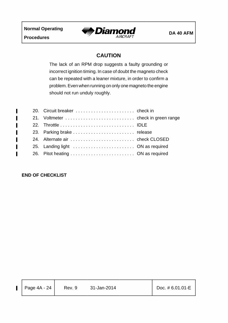
CAUTION
The lack of an RPM drop suggests a faulty grounding or
incorrect ignition timing. In case of doubt the magneto check
can be repeated with a leaner mixture, in order to confirm a
problem. Even when running on only one magneto the engine
should not run unduly roughly.
20. Circuit breaker . . . . . . . . . . . . . . . . . . . . . . . check in%
21. Voltmeter . . . . . . . . . . . . . . . . . . . . . . . . . . . check in green range%
22. Throttle . . . . . . . . . . . . . . . . . . . . . . . . . . . . . IDLE%
23. Parking brake . . . . . . . . . . . . . . . . . . . . . . . . release%
24. Alternate air . . . . . . . . . . . . . . . . . . . . . . . . . check CLOSED%
25. Landing light . . . . . . . . . . . . . . . . . . . . . . . . ON as required%
26. Pitot heating . . . . . . . . . . . . . . . . . . . . . . . . . ON as required%
END OF CHECKLIST
DA 40 AFMNormal Operating
Procedures
Doc. # 6.01.01-E Rev. 8 01-Dec-2010 Page 4A - 33
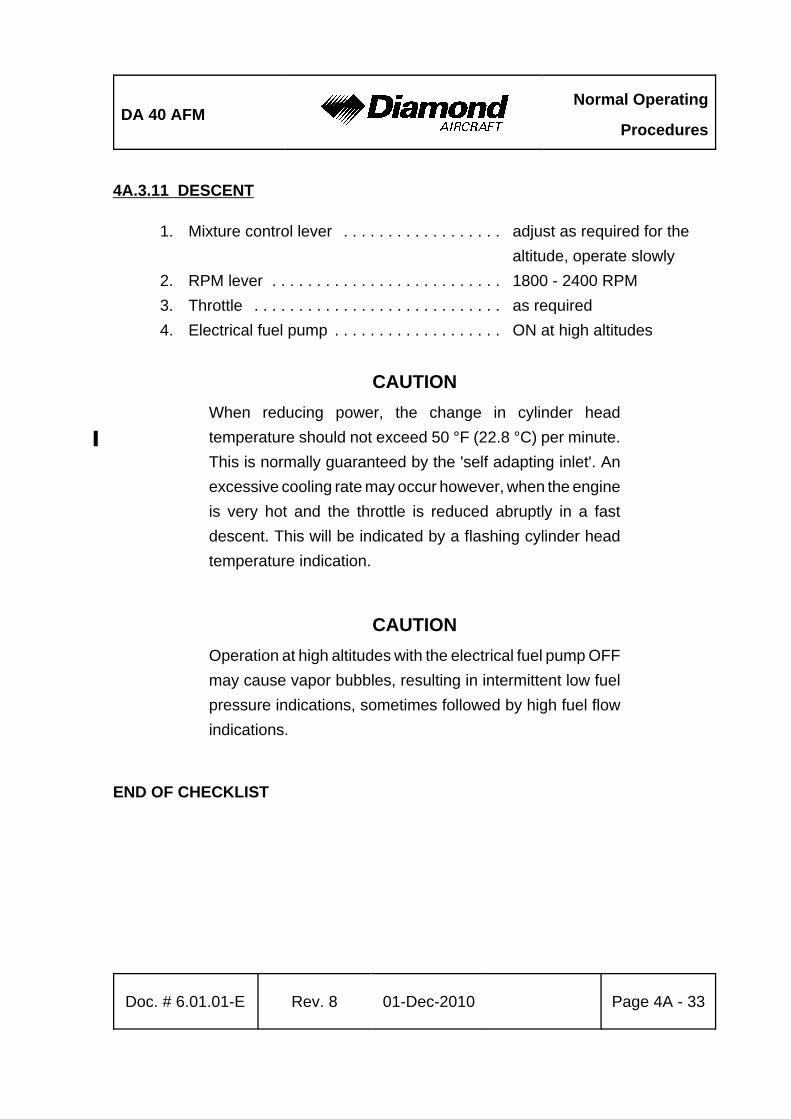
4A.3.11 DESCENT
1. Mixture control lever . . . . . . . . . . . . . . . . . . adjust as required for the
altitude, operate slowly
2. RPM lever . . . . . . . . . . . . . . . . . . . . . . . . . . 1800 - 2400 RPM
3. Throttle . . . . . . . . . . . . . . . . . . . . . . . . . . . . as required
4. Electrical fuel pump . . . . . . . . . . . . . . . . . . . ON at high altitudes
CAUTION
When reducing power, the change in cylinder head
temperature should not exceed 50 °F (22.8 °C) per minute.%
This is normally guaranteed by the 'self adapting inlet'. An
excessive cooling rate may occur however, when the engine
is very hot and the throttle is reduced abruptly in a fast
descent. This will be indicated by a flashing cylinder head
temperature indication.
CAUTION
Operation at high altitudes with the electrical fuel pump OFF
may cause vapor bubbles, resulting in intermittent low fuel
pressure indications, sometimes followed by high fuel flow
indications.
END OF CHECKLIST

Normal Operating
ProceduresDA 40 AFM
Page 4A - 34 Rev. 9% 31-Jan-2014% Doc. # 6.01.01-E
4A.3.12 LANDING APPROACH
CAUTION%
For landing the adjustable backrests (if installed) must be%
fixed in the upright position.%
1. Adjustable backrests (if installed) . . . . . . . . adjust to the upright position%
described by a placard on%
the roll-over bar and verify%
proper fixation.%
2. Fuel selector . . . . . . . . . . . . . . . . . . . . . . . . fullest tank%
3. Electrical fuel pump . . . . . . . . . . . . . . . . . . . ON%
4. Safety harnesses . . . . . . . . . . . . . . . . . . . . . fastened%
5. Airspeed . . . . . . . . . . . . . . . . . . . . . . . . . . . . reduce to operate flaps%
(108 KIAS)
6. Flaps . . . . . . . . . . . . . . . . . . . . . . . . . . . . . . T/O%
7. Trim . . . . . . . . . . . . . . . . . . . . . . . . . . . . . . . as required%
8. Landing light . . . . . . . . . . . . . . . . . . . . . . . . as required%
Before Landing:
9. Mixture control lever . . . . . . . . . . . . . . . . . . RICH%
10. RPM lever . . . . . . . . . . . . . . . . . . . . . . . . . . HIGH RPM%
11. Throttle . . . . . . . . . . . . . . . . . . . . . . . . . . . . . as required%
12. Airspeed . . . . . . . . . . . . . . . . . . . . . . . . . . . . reduce to operate flaps%
(91 KIAS)
13. Flaps . . . . . . . . . . . . . . . . . . . . . . . . . . . . . . LDG%
CONTINUED

DA 40 AFMNormal Operating
Procedures
Doc. # 6.01.01-E Rev. 9% 31-Jan-2014% Page 4A - 35
14. Approach speed . . . . . . . . . . . . . . . . . . . . . 73 KIAS (1200 kg, 2646 lb)%
71 KIAS (1150 kg, 2535 lb)
67 KIAS (1092 kg, 2407 lb)
63 KIAS (1000 kg, 2205 lb)
58 KIAS (850 kg, 1874 lb)
CAUTION
In conditions such as (e.g.) strong wind, danger of wind shear
or turbulence a higher approach speed should be selected.
NOTE
In case of airplanes with a maximum landing mass less than
the maximum permitted flight mass, a landing with a higher
mass constitutes an abnormal operating procedure. Refer
to Sections 2.7 - MASS (WEIGHT) and 4B.7 - LANDING
WITH HIGH LANDING MASS.
END OF CHECKLIST

Normal Operating
ProceduresDA 40 AFM
Page 4A - 36 Rev. 8 01-Dec-2010 Doc. # 6.01.01-E
4A.3.13 GO-AROUND
1. Throttle . . . . . . . . . . . . . . . . . . . . . . . . . . . . . MAX PWR
2. Airspeed . . . . . . . . . . . . . . . . . . . . . . . . . . . . 67 KIAS (1200 kg, 2646 lb)%
66 KIAS (1150 kg, 2535 lb)
60 KIAS (1000 kg, 2205 lb)
54 KIAS (850 kg, 1874 lb)
3. Flaps . . . . . . . . . . . . . . . . . . . . . . . . . . . . . . T/O
Above a Safe Height:
4. RPM lever . . . . . . . . . . . . . . . . . . . . . . . . . . 2400 RPM
5. Airspeed . . . . . . . . . . . . . . . . . . . . . . . . . . . . 76 KIAS (1200 kg, 2646 lb)%
73 KIAS (1150 kg, 2535 lb)
68 KIAS (1000 kg, 2205 lb)
60 KIAS (850 kg, 1874 lb)
6. Flaps . . . . . . . . . . . . . . . . . . . . . . . . . . . . . . UP
7. Electrical fuel pump . . . . . . . . . . . . . . . . . . . OFF
END OF CHECKLIST
DA
40
AF
MM
ass
and
Bal
ance
Doc
. N
o. 6
.01.
01-E
Rev
. 9
%31
-Jan
-201
4%
Pag
e 6
- 17
Airp
lane
Ser
ial N
o.:
Reg
istr
atio
n:D
ate:
Mas
sLe
ver A
rm
Des
crip
tion
Type
Part
No.
Man
ufac
ture
rS/
Nin
stal
led
lbkg
inm
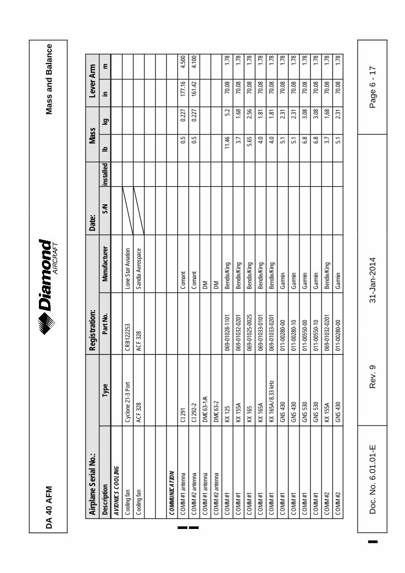
AVIO
NICS
COO
LING
Coo
ling
fan
Cyc
lone
21-
3 Po
rtC
RB1
2225
3Lo
ne S
tar A
viat
ion
Coo
ling
fan
ACF
328
ACF
328
Sand
ia A
eros
pace
COMM
UNIC
ATIO
N
CO
MM
#1
ante
nna
%C
I 291
%%C
oman
t%%%
0.5
%0.
227
%17
7.16
%4.
500
%C
OM
M #
2 an
tenn
a%
CI 2
92-2
%%C
oman
t%%%
0.5
%0.
227
%16
1.42
%4.
100
%C
OM
M #
1 an
tenn
aD
MC
63-1
/AD
M
CO
MM
#2
ante
nna
DM
C63
-2D
M
CO
MM
#1
KX 1
2506
9-01
028-
1101
Bend
ix/K
ing
11.4
65.
270
.08
1.78
CO
MM
#1
KX 1
55A
069-
0103
2-02
01Be
ndix
/Kin
g3.
71.
6870
.08
1.78
CO
MM
#1
KX 1
6506
9-01
025-
0025
Bend
ix/K
ing
5.65
2.56
70.0
81.
78
CO
MM
#1
KX 1
65A
069-
0103
3-01
01Be
ndix
/Kin
g4.
01.
8170
.08
1.78
CO
MM
#1
KX 1
65A/
8.3
3 kH
z06
9-01
033-
0201
Bend
ix/K
ing
4.0
1.81
70.0
81.
78
CO
MM
#1
GN
S 43
0 01
1-00
280-
00G
arm
in5.
12.
3170
.08
1.78
CO
MM
#1
GN
S 43
001
1-00
280-
10G
arm
in5.
12.
3170
.08
1.78
CO
MM
#1
GN
S 53
001
1-00
550-
00G
arm
in6.
83.
0870
.08
1.78
CO
MM
#1
GN
S 53
001
1-00
550-
10G
arm
in6.
83.
0870
.08
1.78
CO
MM
#2
KX 1
55A
069-
0103
2-02
01Be
ndix
/Kin
g3.
71,
6870
.08
1.78
CO
MM
#2
GN
S 43
0 01
1-00
280-
00G
arm
in5.
12.
3170
.08
1.78

DA
40
AF
MM
ass
and
Bal
ance
Airp
lane
Ser
ial N
o.:
Reg
istr
atio
n:D
ate:
Mas
sLe
ver A
rm
Des
crip
tion
Type
Part
No.
Man
ufac
ture
rS/
Nin
stal
led
lbkg
inm
Doc
. N
o. 6
.01.
01-E
Rev
. 9
%31
-Jan
-201
4%
Pag
e 6
- 18
CO
MM
#2
GN
S 43
001
1-00
280-
10G
arm
in5.
12.
3170
.08
1.78
Audi
o Pa
nel /
Mar
ker /
ICS
KMA
2806
6-01
176-
0101
Bend
ix/K
ing
1.5
0.68
70.0
81.
78
Audi
o Pa
nel /
Mar
ker /
ICS
GM
A 34
001
1-00
401-
10G
arm
in1.
20.
5470
.08
1.78
ICS
PM10
00 II
1192
2PS
Eng
inee
ring
0.75
0.34
70.0
81.
78
Hea
dset
, pilo
tEc
helo
n 10
0Te
lex
Hea
dset
, co-
pilo
tEc
helo
n 10
0Te
lex
Hea
dset
, LH
pax
Eche
lon
100
Tele
x
Hea
dset
, RH
pax
Eche
lon
100
Tele
x
Spea
ker
FRS8
/ 4
Ohm
sVi
sato
n
Han
dmic
100T
RA
6280
0-00
1Te
lex
AUTO
PILO
T SY
STEM
Auto
pilo
t sys
tem
KAP
140
Bend
ix/K
ing
Flig
ht c
ompu
ter (
w/o
alt.
pre
sele
ct)
KC 1
4006
5-00
176-
5402
(with
out M
ÄM 4
0-09
9 or
MSB
40-
018)
Bend
ix/K
ing
2.02
0.91
870
.08
1.78
Flig
ht c
ompu
ter (
with
alt.
pre
sele
ct)
KC 1
4006
5-00
176-
7702
(with
out M
ÄM 4
0-09
9 or
MSB
40-
018)
Bend
ix/K
ing
2.02
0.91
870
.08
1.78
Flig
ht c
ompu
ter (
w/o
alt.
pre
sele
ct)
KC 1
4006
5-00
176-
5403
(with
MÄM
40-
099
orM
SB 4
0-01
8)Be
ndix
/Kin
g2.
020.
918
70.0
81.
78

DA
40
AF
MM
ass
and
Bal
ance
Airp
lane
Ser
ial N
o.:
Reg
istr
atio
n:D
ate:
Mas
sLe
ver A
rm
Des
crip
tion
Type
Part
No.
Man
ufac
ture
rS/
Nin
stal
led
lbkg
inm
Doc
. N
o. 6
.01.
01-E
Rev
. 9
%31
-Jan
-201
4%
Pag
e 6
- 19
Flig
ht c
ompu
ter (
with
alt.
pre
sele
ct)
KC 1
4006
5-00
176-
7703
(with
MÄM
40-
099
orM
SB 4
0-01
8)Be
ndix
/Kin
g2.
020.
918
70.0
81.
78
Flig
ht c
ompu
ter
KC 1
4006
5-00
176-
7904
Bend
ix/K
ing
2.02
0.91
870
.08
1.78
Pitc
h se
rvo
KS 2
70 C
065-
0017
8-25
00Be
ndix
/Kin
g2.
71.
224
154.
03.
93
Pitc
h se
rvo
mou
ntKM
275
065-
0003
0-00
00Be
ndix
/Kin
g1.
080.
488
154.
03.
93
Rol
l ser
voKS
271
C
065-
0017
9-03
00Be
ndix
/Kin
g2.
31.
044
120.
03.
06
Rol
l ser
vo m
ount
KM 2
7506
5-00
030-
0000
Bend
ix/K
ing
2.7
1.22
412
0.0
3.06
Trim
ser
voKS
272
C06
5-00
180-
3500
Bend
ix/K
ing
2.22
1.00
587
.22.
21
Trim
ser
vo m
ount
KM 2
7706
5-00
041-
0000
Bend
ix/K
ing
1.09
0.49
487
.22.
21
Con
figur
atio
n m
odul
eKC
M 1
0007
1-00
073-
5000
Bend
ix/K
ing
0.06
0.02
670
.08
1.78
Sona
lert
SCSC
628
Mal
lory
Con
trol s
tick
DA4
-221
3-12
-90
Dia
mon
d
CW
S st
ick
031-
0051
4-00
00Be
ndix
/Kin
g
AP-d
isc
switc
h03
1-00
428-
0000
Bend
ix/K
ing
Trim
sw
itch
assy
200-
0918
7-00
00Be
ndix
/Kin
g
ELEC
TRIC
AL P
OWER
Batte
ryC
B24-
11M
(G24
3)C
onco
rde
(Gill)
28.0
12.7
47.0
1.19
Batte
ryR
G24
-11M
Con
cord
e26
.411
.97
47.0
1.19
Batte
ryR
G24
-15M
Con
cord
e29
.513
.38
47.0
1.19

DA
40
AF
MM
ass
and
Bal
ance
Airp
lane
Ser
ial N
o.:
Reg
istr
atio
n:D
ate:
Mas
sLe
ver A
rm
Des
crip
tion
Type
Part
No.
Man
ufac
ture
rS/
Nin
stal
led
lbkg
inm
Doc
. N
o. 6
.01.
01-E
Rev
. 9
%31
-Jan
-201
4%
Pag
e 6
- 20
Emer
genc
y ba
ttery
(28
pcs.
)M
N 1
500
AAD
urac
ell
1.52
0.69
70.0
81.
78
Emer
genc
y ba
ttery
(Lith
ium
)D
41-2
560-
93-0
0Ex
cell
0.56
40.
256
66.5
1.69
Amm
eter
VM10
0040
1005
0Vi
sion
Mic
rosy
st.
Amm
eter
cur
rent
sen
sor
VM10
0030
1002
2Vi
sion
Mic
rosy
st.
Voltm
eter
VM10
0040
1005
0Vi
sion
Mic
rosy
st.
Volta
ge re
gula
tor
VR20
00-2
8-1
(D)
Elec
trosy
st.,
Inc.
Exte
rnal
pow
er c
onne
ctor
Dia
mon
d
Alte
rnat
orAL
U-8
521L
SAL
U-8
521L
SEl
ectro
syst
., In
c.
DC
-AC
Inve
rter
MD
26
MD
26-
28M
id C
ontin
ent
EQUI
PMEN
T
Safe
ty b
elt,
pilo
t5-
01-()
Ser
ies
5-01
-1C
0701
Schr
oth
3.36
1.52
492
.52
2.35
Safe
ty b
elt,
co-p
ilot
5-01
-() S
erie
s5-
01-1
C57
01Sc
hrot
h3.
361.
524
92.5
22.
35
Safe
ty b
elt,
LH p
ax5-
01-()
Ser
ies
5-01
-1B5
701
Schr
oth
3.0
1.36
126.
73.
22
Safe
ty b
elt,
RH
pax
5-01
-() S
erie
s5-
01-1
B070
1Sc
hrot
h3.
01.
3612
6.7
3.22
Safe
ty b
elt r
ecep
tacl
e, p
ilot
Schr
oth
0.54
0.24
592
.52
2.35
Safe
ty b
elt r
ecep
tacl
e, c
o-pi
lot
Schr
oth
0.54
0.24
592
.52
2.35
Safe
ty b
elt r
ecep
tacl
e, L
H p
axSc
hrot
h0.
540.
245
126.
73.
22
Safe
ty b
elt r
ecep
tacl
e, R
H p
axSc
hrot
h0.
540.
245
126.
73.
22
ELT
unit
E-01
ACK
31.
3617
3.2
4.40

DA
40
AF
MM
ass
and
Bal
ance
Airp
lane
Ser
ial N
o.:
Reg
istr
atio
n:D
ate:
Mas
sLe
ver A
rm
Des
crip
tion
Type
Part
No.
Man
ufac
ture
rS/
Nin
stal
led
lbkg
inm
Doc
. N
o. 6
.01.
01-E
Rev
. 9
%31
-Jan
-201
4%
Pag
e 6
- 21
ELT
rem
ote
switc
hE0
105
ACK
ELT
ante
nna
E010
9AC
K
ELT
unit
JE2-
NG
JE-1
978-
1NG
Jollie
t2.
431.
117
3.2
4.40
ELT
rem
ote
switc
hJE
-197
8-16
Jollie
t
ELT
ante
nna
JE-1
978-
73Jo
lliet
ELT
unit
ME
406
453-
6603
Arte
x2
0.91
173.
24.
40
ELT
buzz
er45
2-65
05Ar
tex
ELT
ante
nna
WH
IP11
0-77
3Ar
tex
ELT
rem
ote
switc
h (A
CE)
453-
0023
Arte
x
ELT
mod
ule
inte
rface
453-
1101
Arte
x
Win
ter b
affle
DA4
-215
7-00
-00
Dia
mon
d
Arm
rest
DA4
-521
0-50
-91
Dia
mon
d
Bagg
age
exte
nsio
n (O
ÄM 4
0-16
3)
Bagg
age
net (
OÄM
40-
163)
Bagg
age
tray
(OÄM
40-
164)
FLIG
HT C
ONTR
OLS
Flap
s co
ntro
l uni
t (in
str.
pane
l)43
0550
Dia
mon
d
Flap
s ac
tuat
or a
ssy
4305
55D
iam
ond
Stal
l war
ning
hor
n as
sy“A
”D
A4-2
739-
10-0
0D
iam
ond

DA
40
AF
MM
ass
and
Bal
ance
Airp
lane
Ser
ial N
o.:
Reg
istr
atio
n:D
ate:
Mas
sLe
ver A
rm
Des
crip
tion
Type
Part
No.
Man
ufac
ture
rS/
Nin
stal
led
lbkg
inm
Doc
. N
o. 6
.01.
01-E
Rev
. 9
%31
-Jan
-201
4%
Pag
e 6
- 22
Stal
l war
ning
hor
n as
sy“B
”D
A4-2
739-
10-0
0X01
Dia
mon
d
Stal
l war
ning
hor
n as
sy“C
”D
A4-2
739-
10-0
0X02
Dia
mon
d
Stal
l war
ning
hor
n as
sy“D
”D
A4-2
739-
10-0
0X03
Dia
mon
d
Stal
l war
ning
hor
n as
sy“E
”D
A4-2
739-
10-0
0X04
Dia
mon
d
Stal
l war
ning
hor
n as
sy“F
”D
A4-2
739-
10-0
0X05
Dia
mon
d
SAFE
TY E
QUIP
MENT
Fire
ext
ingu
ishe
r, po
rtabl
eH
AL 1
AIR
Tot
al4.
852.
211
0.0
2.79
4
Fire
ext
ingu
ishe
r, po
rtabl
e 1)
A 62
0 T
Amer
ex2.
431.
111
0.0
2.79
4
Firs
t aid
kit
Emer
genc
y ax
eG
4591
2Fi
skar
s1.
230.
558
78.7
42.
00
FUEL
Fuel
qty
indi
cato
rVM
1000
4010
028
Visi
on M
icro
syst
.
Fuel
qty
sen
sor L
HVM
1000
3010
0-11
Visi
on M
icro
syst
.
Fuel
qty
sen
sor R
HVM
1000
3010
0-11
Visi
on M
icro
syst
.
Fuel
qty
sen
sor L
H (a
uxilia
ry fu
el)
VM10
0030
100-
50Vi
sion
Mic
rosy
st.
Fuel
qty
sen
sor R
H (a
uxilia
ry fu
el)
VM10
0030
100-
50Vi
sion
Mic
rosy
st.

DA
40
AF
MM
ass
and
Bal
ance
Airp
lane
Ser
ial N
o.:
Reg
istr
atio
n:D
ate:
Mas
sLe
ver A
rm
Des
crip
tion
Type
Part
No.
Man
ufac
ture
rS/
Nin
stal
led
lbkg
inm
Doc
. N
o. 6
.01.
01-E
Rev
. 9
%31
-Jan
-201
4%
Pag
e 6
- 23
HYDR
AULI
C
Mas
ter c
ylin
der
%%10
-54
A%
Cle
vela
nd%%%%%%%
Park
ing
valv
e%%
60-5
D%
Cle
vela
nd%%%%%%%
Brak
e as
sem
bly
%%30
-239
B%
Cle
vela
nd%%%%%%%
INDI
CATI
NG / R
EC. S
YSTE
M
Dig
ital c
hron
omet
erLC
-2AT
4201
00As
tro T
ech
Dig
ital c
hron
omet
erM
odel
803
Dav
tron
Flig
ht ti
mer
8500
0-12
Hob
bs
Flig
ht ti
mer
8509
4-12
Hob
bs
Annu
ncia
tor p
anel
(sys
tem
)D
iam
ond
Annu
ncia
tor p
anel
WW
-IDC
001
Whi
te W
ire
CO
det
ecto
rM
odel
452
-201
CO
Gua
rdia
n LL
C
LAND
ING
GEAR
LAND
ING
GEAR
STA
NDAR
D%
FAIR
INGS
%%%%
MLG
whe
el fa
iring
LH
%%D
41-3
213-
91-0
0%
Dia
mon
d Ai
rcra
ft%
MLG
whe
el fa
iring
RH
%%D
41-3
213-
92-0
0%
Dia
mon
d Ai
rcra
ft%
NLG
whe
el p
ant s
hell
LH% %
D41
-322
3-91
-00_
1%
Dia
mon
d Ai
rcra
ft%

DA
40
AF
MM
ass
and
Bal
ance
Airp
lane
Ser
ial N
o.:
Reg
istr
atio
n:D
ate:
Mas
sLe
ver A
rm
Des
crip
tion
Type
Part
No.
Man
ufac
ture
rS/
Nin
stal
led
lbkg
inm
Doc
. N
o. 6
.01.
01-E
Rev
. 9
%31
-Jan
-201
4%
Pag
e 6
- 24
NLG
whe
el p
ant s
hell
RH
% %D
41-3
223-
92-0
0_1
%D
iam
ond
Airc
raft
%N
LG s
trut f
airin
g as
sy% %
DA4
-322
7-90
-00
%D
iam
ond
Airc
raft
% %%%% %%%%LA
NDIN
G GE
AR S
PEED
KIT
% %%%M
LG s
peed
cov
er L
H% %
DA4
-321
9-27
-00_
1%
Dia
mon
d Ai
rcra
ft%
MLG
spe
ed c
over
RH
% %D
A4-3
219-
28-0
0_1
%D
iam
ond
Airc
raft
%M
LG s
heet
cov
er L
H% %
DA4
-321
9-25
-00
%D
iam
ond
Airc
raft
%M
LG s
heet
cov
er R
H% %
DA4
-321
9-26
-00
%D
iam
ond
Airc
raft
%M
LG c
over
spe
ed L
H% %
DA4
-321
9-21
-00
%D
iam
ond
Airc
raft
%M
LG c
over
spe
ed R
H
% %D
A4-3
219-
22-0
0%
Dia
mon
d Ai
rcra
ft%
MLG
stru
t cov
er L
H% %
DA4
-321
9-23
-00
%D
iam
ond
Airc
raft
%M
LG s
trut c
over
RH
% %D
A4-3
219-
24-0
0%
Dia
mon
d Ai
rcra
ft%
NLG
whe
el p
ant s
hell
LH% %
D41
-322
3-91
-00_
1%
Dia
mon
d Ai
rcra
ft%
NLG
whe
el p
ant s
hell
RH
% %D
41-3
223-
92-0
0_1
%D
iam
ond
Airc
raft
%N
LG s
trut c
over
% %D
A4-3
229-
29-0
0%
Dia
mon
d Ai
rcra
ft% %%%% %%%% %%%%

DA
40
AF
MM
ass
and
Bal
ance
Airp
lane
Ser
ial N
o.:
Reg
istr
atio
n:D
ate:
Mas
sLe
ver A
rm
Des
crip
tion
Type
Part
No.
Man
ufac
ture
rS/
Nin
stal
led
lbkg
inm
Doc
. N
o. 6
.01.
01-E
Rev
. 9
%31
-Jan
-201
4%
Pag
e 6
- 25
LAND
ING
GEAR
SM
ALL
TIRE
S AN
D%
FAIR
INGS
or
%LA
NDIN
G GE
AR T
ALL
MLG
WIT
H%
FAIR
INGS
FOR
SM
ALL
TIRE
S%%%%
MLG
whe
el fa
iring
ass
y sm
all t
ire L
H% %
DA4
-321
5-91
-00
%D
iam
ond
Airc
raft
%M
LG w
heel
fairi
ng a
ssy
smal
l tire
RH
% %D
A4-3
215-
92-0
0%
Dia
mon
d Ai
rcra
ft%
NLG
whe
el fa
iring
she
ll LH
% %D
A4-3
225-
91-0
0%
Dia
mon
d Ai
rcra
ft%
NLG
whe
el fa
iring
she
ll R
H% %
DA4
-322
5-92
-00
%D
iam
ond
Airc
raft
%
Brac
ket a
ssy
LH M
LG w
heel
fairi
ng% %
DA4
-321
5-31
-00
%D
iam
ond
Airc
raft
%
Brac
ket a
ssy
RH
MLG
whe
el fa
iring
% %D
A4-3
215-
32-0
0%
Dia
mon
d Ai
rcra
ft%
Brak
e co
ver M
LG w
heel
fram
e LH
% %D
A4-3
215-
93-0
0%
Dia
mon
d Ai
rcra
ft%
Brak
e co
ver M
LG w
heel
fram
e R
H% %
DA4
-321
5-94
-00
%D
iam
ond
Airc
raft
%N
LG s
trut f
airin
g as
sy% %
DA4
-322
7-90
-00
%D
iam
ond
Airc
raft
% %%%% %%%% %%%% %%%% %%%% %%%%

DA
40
AF
MM
ass
and
Bal
ance
Airp
lane
Ser
ial N
o.:
Reg
istr
atio
n:D
ate:
Mas
sLe
ver A
rm
Des
crip
tion
Type
Part
No.
Man
ufac
ture
rS/
Nin
stal
led
lbkg
inm
Doc
. N
o. 6
.01.
01-E
Rev
. 9
%31
-Jan
-201
4%
Pag
e 6
- 26
LAND
ING
GEAR
SM
ALL
TIRE
S AN
D%
FAIR
INGS
WIT
H M
AINT
ENAN
CE%
ACCE
SS o
r%
LAND
ING
GEAR
TAL
L M
LG W
ITH
%FA
IRIN
GS F
OR S
MAL
L TI
RES
WIT
H%
MAI
NTEN
ANCE
ACC
ESS
%%%%
MLG
whe
el fa
iring
ass
y ac
cess
doo
r%
LH%%
DA4
-321
5-91
-00X
01%
Dia
mon
d Ai
rcra
ft%
MLG
whe
el fa
iring
ass
y ac
cess
doo
r%
RH
%%D
A4-3
215-
92-0
0X01
%D
iam
ond
Airc
raft
%
NLG
whe
el fa
iring
she
ll LH
% %D
A4-3
225-
91-0
0X01
%D
iam
ond
Airc
raft
%N
LG w
heel
fairi
ng s
hell
RH
% %D
A4-3
225-
92-0
0%
Dia
mon
d Ai
rcra
ft%
Brac
ket a
ssy
LH M
LG w
heel
fairi
ng% %
DA4
-321
5-31
-00
%D
iam
ond
Airc
raft
%Br
acke
t ass
y R
H M
LG w
heel
fairi
ng% %
DA4
-321
5-32
-00
%D
iam
ond
Airc
raft
%Br
ake
cove
r MLG
whe
el fr
ame
LH% %
DA4
-321
5-93
-00
%D
iam
ond
Airc
raft
%Br
ake
cove
r MLG
whe
el fr
ame
RH
% %D
A4-3
215-
94-0
0%
Dia
mon
d Ai
rcra
ft%
NLG
stru
t fai
ring
assy
% %D
A4-3
227-
90-0
0%
Dia
mon
d Ai
rcra
ft%
LIGH
TS
Map
/ R
eadi
ng li
ght a
ssy
crew
W14
61.0
.010
Riv
oret
Cab
in L
ight
W14
61.0
.010
Riv
oret
Inst
r./ra
dio
light
s di
mm
er a
ssy
WW
-LC
M-0
02W
hite
Wire

DA
40
AF
MM
ass
and
Bal
ance
Airp
lane
Ser
ial N
o.:
Reg
istr
atio
n:D
ate:
Mas
sLe
ver A
rm
Des
crip
tion
Type
Part
No.
Man
ufac
ture
rS/
Nin
stal
led
lbkg
inm
Doc
. N
o. 6
.01.
01-E
Rev
. 9
%31
-Jan
-201
4%
Pag
e 6
- 27
Gla
resh
ield
lam
p as
syD
A4-3
311-
10-0
1D
iam
ond
Airc
raft
Gla
resh
ield
ligh
t inv
erte
rAP
VL32
8-8-
3-L-
18Q
FQ
uant
afle
x
Stro
be /
Pos.
ligh
t ass
y LH
A600
-PR
-D-2
801
-079
0006
-05
Whe
len
Stro
be /
Pos.
ligh
t ass
y R
HA6
00-P
G-D
-28
01-0
7900
06-0
7W
hele
n
Stro
be /
Pos.
ligh
t ass
y LH
%0R
6002
R%
01-0
7717
33-1
2%
Whe
len
% %%%%%%St
robe
/ Po
s. li
ght a
ssy
RH
%0R
6002
G%
01-0
7717
33-1
1%
Whe
len
% %%%%%%St
robe
ligh
t pow
er s
uppl
y LH
/RH
A490
ATS-
CF–
14/2
801
-077
0062
-05
Whe
len
1.59
20.
722
101.
02.
566
Hal
ogen
Tax
i lig
ht%
7034
6-01
%01
-077
0346
-05
Whe
len
0.28
%0.
13%
79.9
20%
2.03
0%
Hal
ogen
Lan
ding
ligh
t%
7034
6-01
%01
-077
0346
-03
Whe
len
0.28
%0.
13%
79.9
20%
2.03
0%
Elec
tro lu
min
esce
nt la
mps
Qua
ntaf
lex
1600
Qua
ntaf
lex
Balla
stG
ENS
D1,
24V
3777
6N
ewar
k
Balla
stG
ENS
D1,
24V
3777
6N
ewar
k
Taxi
ligh
tH
ID L
AMP
D15
3966
3N
ewar
k
Land
ing
light
HID
LAM
P D
1539
663
New
ark
LED
Tax
i lig
ht%
7112
5%
01-0
7711
25-2
3%
Whe
len
% %%0.
3%
0.14
%79
.920
2.03
0
LED
Lan
ding
ligh
t%
7112
5%
01-0
7711
25-2
0%
Whe
len
% %%0.
3%
0.14
%79
.920
2.03
0

DA
40
AF
MM
ass
and
Bal
ance
Airp
lane
Ser
ial N
o.:
Reg
istr
atio
n:D
ate:
Mas
sLe
ver A
rm
Des
crip
tion
Type
Part
No.
Man
ufac
ture
rS/
Nin
stal
led
lbkg
inm
Doc
. N
o. 6
.01.
01-E
Rev
. 9
%31
-Jan
-201
4%
Pag
e 6
- 28
NAVI
GATI
ON
Pito
t/sta
tic p
robe
, hea
ted
DAI
-903
4-57
-00
Dia
mon
d
P/S
prob
e H
TR fa
il se
nsor
DA4
-303
1-01
-00
Dia
mon
d
Altim
eter
inH
g/m
bar,
prim
ary
5934
PD-3
Uni
ted
Inst
rum
ents
1.9
0.86
70.0
81.
78
Altim
eter
inH
g/m
bar,
prim
ary
LUN
112
811
28-1
4B6
Mik
rote
chna
1.39
0.63
70.0
81.
78
Altim
eter
inH
g/m
bar,
seco
ndar
y59
34PD
-3U
nite
d In
stru
men
ts1.
90.
8670
.08
1.78
Altim
eter
inH
g/m
bar,
seco
ndar
yLU
N 1
128
1128
-14B
6M
ikro
tech
na1.
390.
6370
.08
1.78
Verti
cal s
peed
indi
cato
r70
00U
nite
d In
stru
men
ts1.
20.
5470
.08
1.78
Verti
cal s
peed
indi
cato
rLU
N 1
144
1144
-A4B
4M
ikro
tech
na0.
90.
470
.08
1.78
Airs
peed
indi
cato
r80
25U
nite
d In
stru
men
ts0.
70.
3270
.08
1.78
Airs
peed
indi
cato
rLU
N 1
116
1116
-B4B
3M
ikro
tech
na0.
770.
3570
.08
1.78
Out
side
air
tem
p. in
dica
tion
301F
(C)
Dav
tron
0.27
0.12
470
.08
1.78
Mag
netic
com
pass
C24
00L4
PAi
rpat
h0.
650.
293
70.0
81.
78
Com
pass
sys
tem
C/O
KCS
55A
Bend
ix/K
ing
Sl
aved
gyr
oKG
102
A06
0-00
015-
0000
Bend
ix/K
ing
4.3
1.95
70.0
81.
78
H
SIKI
525
A06
6-03
046-
0007
Bend
ix/K
ing
3.38
1.53
70.0
81.
78
Sl
avin
g un
it (v
ertic
al)
KA 5
1B07
1-01
242-
0001
Bend
ix/K
ing
0.2
0.91
70.0
81.
78
Sl
avin
g un
it (h
oriz
onta
l)KA
51B
071-
0124
2-06
Bend
ix/K
ing
0.2
0.91
70.0
81.
78
Fl
ux v
alve
KMT
112
071-
0105
2-00
00Be
ndix
/Kin
g0.
30.
1410
1.0
2.56
6
Dire
ctio
nal g
yro,
free
AIM
2051
BLD
505-
0031
-931
BF-G
oodr
ich
2.6
1.18
70.0
81.
78

DA
40
AF
MM
ass
and
Bal
ance
Airp
lane
Ser
ial N
o.:
Reg
istr
atio
n:D
ate:
Mas
sLe
ver A
rm
Des
crip
tion
Type
Part
No.
Man
ufac
ture
rS/
Nin
stal
led
lbkg
inm
Doc
. N
o. 6
.01.
01-E
Rev
. 9
%31
-Jan
-201
4%
Pag
e 6
- 29
Attit
ude
indi
cato
rAI
M11
00-2
8L(0
F)50
4-01
11-9
36BF
-Goo
dric
h2.
201.
070
.08
1.78
Attit
ude
indi
cato
rAI
M11
00-2
8LK(
0F)
504-
0111
-938
BF-G
oodr
ich
2.20
1.0
70.0
81.
78
Attit
ude
indi
cato
rAI
M11
00-2
8LK(
2F)
504-
0111
-941
BF-G
oodr
ich
2.20
1.0
70.0
81.
78
Turn
coo
rdin
ator
w/o
AP
pick
up13
94T1
00-(3
Z)M
id C
ontin
ent I
nstr.
0.82
20.
373
70.0
81.
78
Turn
coo
rdin
ator
13
94T1
00-(1
2RZ)
Mid
Con
tinen
t Ins
tr.1.
410.
6470
.08
1.78
Turn
coo
rdin
ator
1394
T100
-(12R
A)M
id C
ontin
ent I
nstr.
1.41
0.64
70.0
81.
78
Turn
coo
rdin
ator
1394
T100
-(12R
B)M
id C
ontin
ent I
nstr.
1.41
0.64
70.0
81.
78
Mar
ker a
nten
naC
I102
Com
ant
DM
EKN
62A
066-
0106
8-00
04Be
ndix
/Kin
g2.
61.
1870
.08
1.78
DM
E an
tenn
aKA
6007
1-01
174-
0000
Bend
ix/K
ing
DM
E an
tenn
aKA
6007
1-01
591-
0001
Bend
ix/K
ing
DM
E an
tenn
aKA
6107
1-00
221-
0010
Bend
ix/K
ing
Tran
spon
der
KT 7
6A06
6-10
62-1
0Be
ndix
/Kin
g0.
850.
3970
.08
1.78
Tran
spon
der
KT 7
6C06
6-01
156-
0101
Bend
ix/K
ing
0.2
0.09
70.0
81.
78
Tran
spon
der
GTX
327
011-
0049
0-00
Gar
min
2.4
1.09
70.0
81.
78
Tran
spon
der
GTX
330
011-
0045
5-00
Gar
min
3.4
1.54
70.0
81.
78
XPD
R a
nten
naKA
6007
1-01
174-
0000
Bend
ix/K
ing
XPD
R a
nten
naKA
6007
1-01
591-
0001
Bend
ix/K
ing
XPD
R a
nten
naKA
6107
1-00
221-
0010
Bend
ix/K
ing
Altit
ude
digi
tizer
D12
0-P2
-TTC
I

DA
40
AF
MM
ass
and
Bal
ance
Airp
lane
Ser
ial N
o.:
Reg
istr
atio
n:D
ate:
Mas
sLe
ver A
rm
Des
crip
tion
Type
Part
No.
Man
ufac
ture
rS/
Nin
stal
led
lbkg
inm
Doc
. N
o. 6
.01.
01-E
Rev
. 9
%31
-Jan
-201
4%
Pag
e 6
- 30
Altit
ude
data
sys
tem
SAE5
-35
3051
54-0
0Sa
ndia
Aer
ospa
ce
ADF
KR87
066-
0107
2-00
04Be
ndix
/Kin
g2.
91.
3270
.08
1.78
ADF
ante
nna
KA44
B07
1-01
234-
0000
Bend
ix/K
ing
ADF
indi
cato
rKI
227
066-
0306
3-00
01Be
ndix
/Kin
g0.
70.
3270
.08
1.78
ADF
indi
cato
rKI
227
066-
0306
3-00
Bend
ix/K
ing
0.7
0.32
70.0
81.
78
NAV
ant
enna
cou
pler
CI5
05C
oman
t
NAV
/GS
ante
nna
coup
ler
CI5
07C
oman
t0.
200.
089
106.
12.
685
dual
NAV
/dua
l GS
ante
nna
coup
ler
CI 1
125
Com
ant
VOR
/LO
C/G
S an
tenn
aC
I157
PC
oman
t
NAV
/CO
M #
1KX
125
069-
0102
8-11
01Be
ndix
/Kin
g11
.46
5.2
70.0
81.
78
NAV
/CO
M #
1 vo
lt co
nv.
KA39
07
1-01
041-
001
Bend
ix/K
ing
NAV
/CO
M #
1KX
155A
06
9-01
032-
0201
Bend
ix/K
ing
3.7
1.68
70.0
81.
78
NAV
/CO
M #
1KX
165
069-
0102
5-00
25Be
ndix
/Kin
g5.
652.
5670
.08
1.78
NAV
/CO
M #
1KX
165
A06
9-01
033-
0101
Bend
ix/K
ing
4.0
1.81
70.0
81.
78
NAV
/CO
M #
1KX
165
A, 8
.33
kHz
069-
0103
3-02
01Be
ndix
/Kin
g4.
01.
8170
.08
1.78
NAV
/CO
M #
2KX
155A
06
9-01
032-
0201
Bend
ix/K
ing
3.7
1.68
70.0
81.
78
NAV
CO
M/G
PS #
1G
NS
430
011-
0028
0-00
Gar
min
6.5
2.95
70.0
81.
78
NAV
CO
M/G
PS #
1G
NS
430
011-
0028
0-10
Gar
min
6.5
2.95
70.0
81.
78
NAV
CO
M/G
PS #
1G
NS
530
011-
0055
0-00
Gar
min
8.5
3.86
70.0
81.
78
NAV
CO
M/G
PS #
1G
NS
530
011-
0055
0-0
Gar
min
8.5
3.86
70.0
81.
78

DA
40
AF
MM
ass
and
Bal
ance
Airp
lane
Ser
ial N
o.:
Reg
istr
atio
n:D
ate:
Mas
sLe
ver A
rm
Des
crip
tion
Type
Part
No.
Man
ufac
ture
rS/
Nin
stal
led
lbkg
inm
Doc
. N
o. 6
.01.
01-E
Rev
. 9
%31
-Jan
-201
4%
Pag
e 6
- 31
NAV
CO
M/G
PS #
2G
NS
430
011-
0028
0-00
Gar
min
6.5
2.95
70.0
81.
78
NAV
CO
M/G
PS #
2G
NS
430
011-
0028
0-10
Gar
min
6.5
2.95
70.0
81.
78
CD
I, VO
R/L
OC
#1
KI 2
0806
6-03
056-
0000
Bend
ix/K
ing
10.
4570
.08
1.78
CD
I, VO
R/L
OC
#2
KI 2
0806
6-03
056-
0000
Bend
ix/K
ing
10.
4570
.08
1.78
CD
I, VO
R/L
OC
/GS
#1G
I 106
A01
3-00
049-
01G
arm
in1.
40.
6470
.08
1.78
CD
I, VO
R/L
OC
/GS
#2G
I 106
A01
3-00
049-
01G
arm
in1.
40.
6470
.08
1.78
GPS
KLN
89
B06
6-01
148-
0102
Bend
ix/K
ing
31.
3670
.08
1.78
GPS
KLN
94
069-
0103
4-01
01Be
ndix
/Kin
g3
1.36
70.0
81.
78
GPS
ant
enna
KA 9
207
1-01
553-
0200
Bend
ix/K
ing
GPS
ant
enna
#1
GA
5601
1-00
134-
00G
arm
in
GPS
ant
enna
#2
GA
5601
1-00
134-
00G
arm
in
GPS
ann
unci
atio
n un
itM
D41
-148
8M
id C
ontin
ent
GPS
/ AP
sw
itch
assy
MD
41-5
28M
id C
ontin
ent
Mul
tifun
ctio
n di
spla
y / G
PSKM
D 1
5006
6-01
174-
0101
Bend
ix/K
ing
3.3
1.5
70.0
81.
78
Stor
msc
ope
WX-
500
805-
1150
0-00
1G
oodr
ich
Stor
msc
ope
ante
nna
NY-
163
805-
1093
0-00
1G
oodr
ich
Strik
e fin
der d
ispl
aySF
200
020
00-0
09In
sigh
t
Strik
e fin
der s
enso
rSF
200
020
00-0
22In
sigh
t
TAS
proc
esso
rTA
S 60
070
-242
0-x
TAS6
00Av
idyn
e/R
yan
TAS
proc
esso
rTA
S 61
070
-242
0-x
TAS6
10Av
idyn
e/R
yan
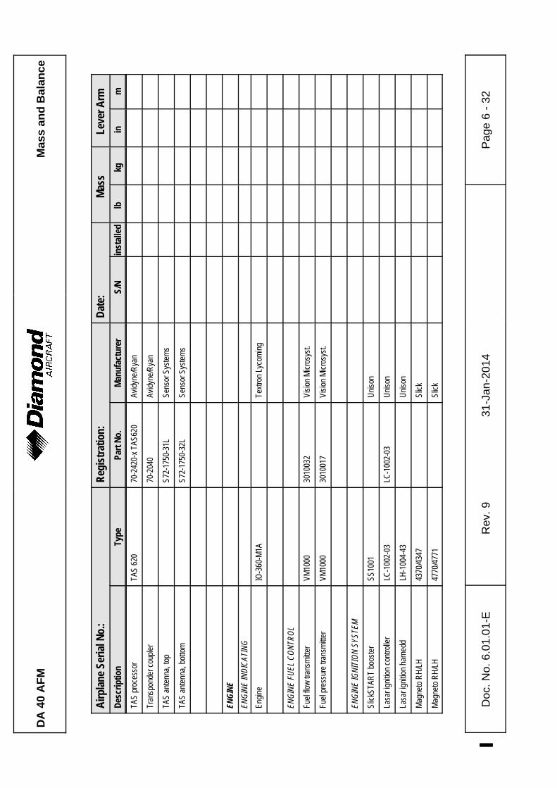
DA
40
AF
MM
ass
and
Bal
ance
Airp
lane
Ser
ial N
o.:
Reg
istr
atio
n:D
ate:
Mas
sLe
ver A
rm
Des
crip
tion
Type
Part
No.
Man
ufac
ture
rS/
Nin
stal
led
lbkg
inm
Doc
. N
o. 6
.01.
01-E
Rev
. 9
%31
-Jan
-201
4%
Pag
e 6
- 32
TAS
proc
esso
rTA
S 62
070
-242
0-x
TAS6
20Av
idyn
e/R
yan
Tran
spon
der c
oupl
er70
-204
0Av
idyn
e/R
yan
TAS
ante
nna,
top
S72-
1750
-31L
Sens
or S
yste
ms
TAS
ante
nna,
bot
tom
S72-
1750
-32L
Sens
or S
yste
ms
ENGI
NEEN
GINE
INDI
CATI
NG
Engi
neIO
-360
-M1A
Text
ron
Lyco
min
g
ENGI
NE F
UEL
CONT
ROL
Fuel
flow
tran
smitt
erVM
1000
3010
032
Visi
on M
icro
syst
.
Fuel
pre
ssur
e tra
nsm
itter
VM10
0030
1001
7Vi
sion
Mic
rosy
st.
ENGI
NE IG
NITI
ON S
YSTE
M
Slic
kSTA
RT
boos
ter
SS10
01U
niso
n
Lasa
r ign
ition
con
trolle
rLC
-100
2-03
LC-1
002-
03U
niso
n
Lasa
r ign
ition
har
nedd
LH-1
004-
43U
niso
n
Mag
neto
RH
/LH
4370
/434
7Sl
ick
Mag
neto
RH
/LH
4770
/477
1Sl
ick

DA
40
AF
MM
ass
and
Bal
ance
Airp
lane
Ser
ial N
o.:
Reg
istr
atio
n:D
ate:
Mas
sLe
ver A
rm
Des
crip
tion
Type
Part
No.
Man
ufac
ture
rS/
Nin
stal
led
lbkg
inm
Doc
. N
o. 6
.01.
01-E
Rev
. 9
%31
-Jan
-201
4%
Pag
e 6
- 33
RPM
sen
sor
VM10
0030
1000
5Vi
sion
Mic
rosy
st.
Man
ifold
pre
ssur
e se
nsor
VM10
0030
1001
6Vi
sion
Mic
rosy
st.
Cyl
. hea
d te
mp.
pro
bes
(4 e
ach)
VM10
0010
2006
1Vi
sion
Mic
rosy
st.
EGT
prob
esVM
1000
1020
060
Visi
on M
icro
syst
.
Dat
a pr
oces
sing
uni
tD
PU40
1006
7Vi
sion
Mic
rosy
st.
Dat
a pr
oces
sing
uni
tD
PU40
1008
1Vi
sion
Mic
rosy
st.
Inte
gr. e
ngin
e da
ta d
ispl
ay
VM10
0040
1005
0Vi
sion
Mic
rosy
st.
I/O b
oard
ass
y30
2000
3Vi
sion
Mic
rosy
st.
I/O b
oard
ass
y30
2001
8Vi
sion
Mic
rosy
st.
ENGI
NE O
IL
Oil
tem
pera
ture
sen
sor
VM10
0030
1002
1Vi
sion
Mic
rosy
st.
Oil
pres
sure
tran
sduc
erVM
1000
3010
018
Visi
on M
icro
syst
.
ENGI
NE S
TART
ING
Star
ter
149-
24LS
Skyt
ec

DA
40
AF
MM
ass
and
Bal
ance
Airp
lane
Ser
ial N
o.:
Reg
istr
atio
n:D
ate:
Mas
sLe
ver A
rm
Des
crip
tion
Type
Part
No.
Man
ufac
ture
rS/
Nin
stal
led
lbkg
inm
Doc
. N
o. 6
.01.
01-E
Rev
. 9
%31
-Jan
-201
4%
Pag
e 6
- 34
PROP
ELLE
R SY
STEM
Prop
elle
rM
TV-1
2-B/
180-
17m
t-Pro
pelle
r47
.021
.32
15.0
0.38
1
Prop
elle
rM
TV-1
2-B/
180-
17f
mt-P
rope
ller
47.0
21.3
215
.00.
381
Prop
elle
r gov
erno
rC
-210
776
Woo
dwar
d3.
051.
385
29.4
0.74
7
Prop
elle
r gov
erno
rM
T-P-
420-
10m
t-Pro
pelle
r2.
00.
907
29.4
0.74
7
Prop
elle
r gov
erno
rM
T-P8
60-2
3P-
860-
23m
t-Pro
pelle
r2.
050.
9329
.4
0.74
7
AIRP
LANE
FLI
GHT
MANU
ALD
oc.N
o. 6
.01.
01(-E
)D
iam
ond
1) T
he A
mer
ex A
620
T f
ire e
xtin
guis
her
is U
L ap
prov
ed a
nd c
an b
e us
ed in
airp
lane
s re
gist
ered
in C
anad
a an
d th
e U
SA
. F
or a
irpla
nes
regi
ster
ed in
oth
er c
ount
ries,
ref
er t
o th
e na
tiona
l Airw
orth
ines
s A
utho
rity.
Pla
ce: _
____
____
____
____
___
Dat
e: _
____
____
____
____
____
_S
igna
ture
: ___
____
____
____
____
____
___
DA 40 AFMAirplane
Description
Doc. # 6.01.01-E Rev. 9% 31-Jan-2014% Page 7 - 1
CHAPTER 7
DESCRIPTION OF THE AIRPLANE
AND ITS SYSTEMS
Page
7.1 INTRODUCTION . . . . . . . . . . . . . . . . . . . . . . . . . . . . . . . . . . . . . . . 7-3
7.2 AIRFRAME . . . . . . . . . . . . . . . . . . . . . . . . . . . . . . . . . . . . . . . . . . . 7-3
7.3 FLIGHT CONTROLS . . . . . . . . . . . . . . . . . . . . . . . . . . . . . . . . . . . . 7-4
7.4 INSTRUMENT PANEL . . . . . . . . . . . . . . . . . . . . . . . . . . . . . . . . . 7-10
7.5 LANDING GEAR . . . . . . . . . . . . . . . . . . . . . . . . . . . . . . . . . . . . . . 7-13
7.6 SEATS AND SAFETY HARNESSES . . . . . . . . . . . . . . . . . . . . . . 7-15
7.7 BAGGAGE COMPARTMENT . . . . . . . . . . . . . . . . . . . . . . . . . . . . 7-17%
7.8 CANOPY, REAR DOOR, AND CABIN INTERIOR . . . . . . . . . . . . 7-18%
7.9 POWER PLANT . . . . . . . . . . . . . . . . . . . . . . . . . . . . . . . . . . . . . . 7-21%
7.9.1 ENGINE, GENERAL . . . . . . . . . . . . . . . . . . . . . . . . . . . . . . 7-21%
7.9.2 OPERATING CONTROLS . . . . . . . . . . . . . . . . . . . . . . . . . 7-22%
7.9.3 PROPELLER . . . . . . . . . . . . . . . . . . . . . . . . . . . . . . . . . . . . 7-25%
7.9.4 ENGINE INSTRUMENTS . . . . . . . . . . . . . . . . . . . . . . . . . . 7-26%
7.10 FUEL SYSTEM . . . . . . . . . . . . . . . . . . . . . . . . . . . . . . . . . . . . . . . 7-32%
7.11 ELECTRICAL SYSTEM . . . . . . . . . . . . . . . . . . . . . . . . . . . . . . . . 7-41%
7.11.1 GENERAL . . . . . . . . . . . . . . . . . . . . . . . . . . . . . . . . . . . . . 7-43%
7.11.2 DAI ANNUNCIATOR PANEL(WARNING, CAUTION AND STATUS%
LIGHTS) . . . . . . . . . . . . . . . . . . . . . . . . . . . . . . . . . . . . . . . 7-47%
7.11.3 WHITE WIRE ANNUNCIATOR PANEL(WARNING, CAUTION AND%
STATUS LIGHTS) . . . . . . . . . . . . . . . . . . . . . . . . . . . . . . . 7-50%
7.12 PITOT-STATIC SYSTEM . . . . . . . . . . . . . . . . . . . . . . . . . . . . . . . 7-55%
7.13 STALL WARNING . . . . . . . . . . . . . . . . . . . . . . . . . . . . . . . . . . . . . 7-55%
7.14 AVIONICS . . . . . . . . . . . . . . . . . . . . . . . . . . . . . . . . . . . . . . . . . . . 7-55%
%
Airplane
DescriptionDA 40 AFM
Page 7 - 2 Rev. 9% 31-Jan-2014% Doc. # 6.01.01-E
7.15 CO-MONITOR (IF INSTALLED) . . . . . . . . . . . . . . . . . . . . . . . . . . 7-56%
7.15.1 SELF TEST SEQUENCE . . . . . . . . . . . . . . . . . . . . . . . . . 7-56%
7.15.2 IN-FLIGHT CO ALARM . . . . . . . . . . . . . . . . . . . . . . . . . . . 7-56%
7.15.3 UNIT FAILURE INDICATION . . . . . . . . . . . . . . . . . . . . . . 7-57%

DA 40 AFMAirplane
Description
Doc. # 6.01.01-E Rev. 9% 31-Jan-2014% Page 7 - 15
7.6 SEATS AND SAFETY HARNESSES
To increase passive safety, the seats are constructed using a carbon fiber/Kevlar hybrid
material and GFRP. The seats are removable to facilitate the maintenance and inspection
of the underlying controls. Covers on the control sticks prevent loose objects from falling
into the area of the controls.
If front seats with adjustable backrests are installed (OÄM 40-252), the angle of the%
backrests can be adjusted for best comfort. The backrest lever is situated on the outboard%
side of the backrest. However, during take-off, landing and emergency landing the%
backrests must be fixed in the upright position designated by a placard on the roll-over%
bar. %
CAUTION%
Before the backrest lever is lifted in order to unlock the%
backrest, lean back towards the backrest to counteract the%
spring load; otherwise the backrest may snap forward.%
For adjustment lift the backrest lever and bend forward or backward to the desired backrest%
angle. Then release and press down the backrest lever.%
In case of a defective adjustment mechanism the outboard friction adjustment screw can%
be tightened with a 10 mm hexagon nut in clockwise direction in order to fix the backrest%
in the upright position.%
If possible, set the backrest lever to the „locked" position. The mechanism must be repaired%
at the next scheduled inspection. %
The lumbar support can be adjusted by operating the lumbar support lever mounted on%
the outboard side of the seat pan.%
The seats have removable furnishings and are equipped with energy-absorbing foam
elements.
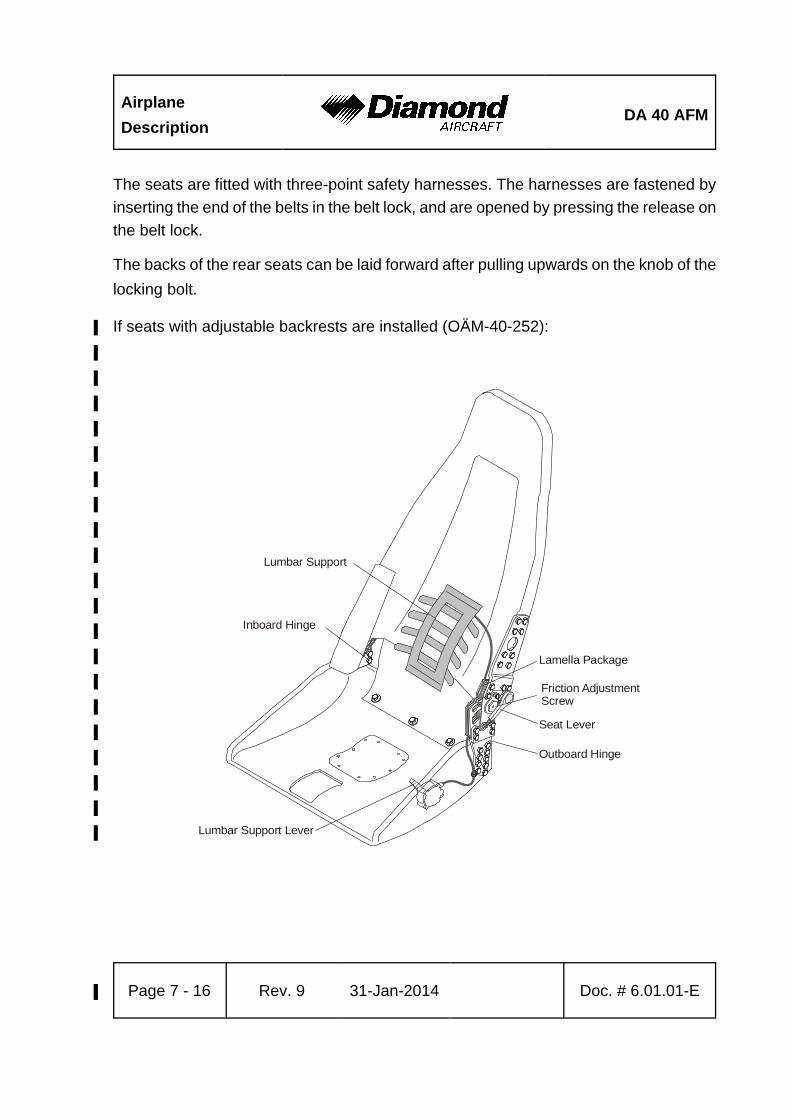
Airplane
DescriptionDA 40 AFM
Page 7 - 16 Rev. 9% 31-Jan-2014% Doc. # 6.01.01-E
Outboard Hinge
Inboard Hinge
Lamella Package
Friction AdjustmentScrew
Seat Lever
Lumbar Support Lever
Lumbar Support
The seats are fitted with three-point safety harnesses. The harnesses are fastened by
inserting the end of the belts in the belt lock, and are opened by pressing the release on
the belt lock.
The backs of the rear seats can be laid forward after pulling upwards on the knob of the
locking bolt.
If seats with adjustable backrests are installed (OÄM-40-252):%
%
%
%
%
%
%
%
%
%
%
%
%
%
%
%
%
%
%
%
%

DA 40 AFMAirplane
Description
Doc. # 6.01.01-E Rev. 9% 31-Jan-2014% Page 7 - 17
7.7 BAGGAGE COMPARTMENT
The DA 40 may be equipped with one of the following baggage compartment variants:
(a) Standard baggage compartment.
(b) Standard baggage compartment with 'baggage tube'.
(c) Extended baggage compartment (OÄM 40-163). It consists of a forward and an
aft part.
Without a baggage net, no baggage may be loaded.
Standard Baggage Compartment
The baggage compartment is located behind the rear seats.
Baggage Tube (if installed)
On the back side of the standard baggage compartment the baggage tube may be
installed. It is separated by a cloth cover.
Extended Baggage Compartment (OÄM 40-163 and OÄM 40-164, if installed)
The extended baggage compartment consists of the standard baggage compartment
behind the rear seats and the baggage extension mounted between the baggage
compartment frame and ring frame No. 1.
The baggage extension has a door that may be hinged up to keep items from sliding aft
or hinged down to carry long items.
The baggage tray may be installed in the bottom of the standard baggage compartment.
The lid of the baggage tray and the bottom of the baggage extension form a flat loading
surface. The lid has mounting provisions for the tow bar. The space under the lid may
be used to carry small items such as the gust lock and the fuel quantity measuring device.

Airplane
DescriptionDA 40 AFM
Page 7 - 18 Rev. 9% 31-Jan-2014% Doc. # 6.01.01-E
7.8 CANOPY, REAR DOOR, AND CABIN INTERIOR
Front Canopy
The front canopy is closed by pulling down on the canopy frame, following which it is locked
by means of a handle on the left hand side of the frame. On locking, steel bolts lock into
mating holes in polyethylene blocks.
“Cooling gap” position: A second setting allows the bolts to lock in, leaving a gap under
the front canopy.
The front canopy can be blocked by a locking device (optional) on the left side near the
canopy opening lever by turning the key clockwise. The closed and blocked canopy can
be opened from inside by pulling the lever inside the opening handle.
WARNING
The airplane may be operated with the front canopy in the
“cooling gap” position on the ground only. Before take-off the
front canopy must be completely closed and locked, but not
blocked with the locking device.
A window on the left hand side of the canopy can be opened for additional ventilation or
as an emergency window. Some serial numbers have another window on the right hand
side of the canopy.

DA 40 AFMAirplane
Description
Doc. # 6.01.01-E Rev. 9% 31-Jan-2014% Page 7 - 19
Rear Door
The rear door is closed in the same way, by pulling down on the frame or on the handle
(if installed) and locking it with the handle. A gas pressure damper prevents the door from
dropping; in strong winds the assembly must be held. The rear door is protected against
unintentional opening by an additional lever.
The door can be blocked by a locking device (optional) on the left side near the door
opening lever by turning the key clockwise. The closed and blocked door can be opened
from inside by pulling the lever inside the opening handle.
WARNING
The rear door must be closed and locked, but not blocked
with the locking device before the engine is started.
Heating and Ventilation
Heating and ventilation are operated using two levers located on the small center console
under the instrument panel.
Left lever: up = heating ON
down = heating OFF
Central lever (Air distribution lever):
up = airflow to canopy (•)
down = airflow to floor (–)

Airplane
DescriptionDA 40 AFM
Page 7 - 20 Rev. 9% 31-Jan-2014% Doc. # 6.01.01-E
Floor Panel
Emergency Axe
If OÄM 40-326 is incorporated an emergency axe is installed on the floor panel under
the pilot’s seat (see Figure below).
If the canopy can not be opened in case of an emergency use the emergency axe to
break through the canopy.
WARNING
Make sure not to harm other persons by using the emergency
axe.
WARNING
Beware of sharp edges and fragments of the broken canopy.

DA 40 AFMAirplane
Description
Doc. # 6.01.01-E Rev. 9% 31-Jan-2014% Page 7 - 21
7.9 POWER PLANT
7.9.1 ENGINE, GENERAL
Lycoming IO-360-M1A: Air-cooled four-cylinder four-stroke engine. Horizontally-opposed
direct-drive engine with fuel injection and underslung exhaust.
Displacement: 5916 cm3 (361 in3).
Max. power: 180 HP (134.2 kW) at 2700 RPM at sea level and ISA.
Max. continuous power: 160 HP (119.3 kW) at 2400 RPM at sea level and ISA.
The principal engine accessories at the front of the engine are the propeller governor,
the starter motor, and the alternator. The ignition (optionally controlled by an electronic
control unit), the twin magneto system and the mechanical fuel pump are at the rear of
the engine. Fuel is supplied via a fuel injection system.
Further information should be obtained from the engine operating manual.
The engine instruments are on the right hand side of the instrument panel.
The ignition switch is designed as a key-operated lock. The ignition is switched on by
moving the switch to the right from the OFF position to the L-R-BOTH positions. A further
turn to the right to the START position will operate the starter motor.

Airplane
DescriptionDA 40 AFM
Page 7 - 22 Rev. 9% 31-Jan-2014% Doc. # 6.01.01-E
7.9.2 OPERATING CONTROLS
The engine performance is controlled by means of three levers: throttle, RPM lever and
mixture control lever, situated together as a group on the large center console (also
referred to as the throttle quadrant). Front and rear are defined in relation to the direction
of flight.
Throttle
- Left hand lever with large, black knob.
This lever is used to set the manifold pressure (MP). When the throttle is furthest forward,
the engine is being provided with extra fuel for high performance settings.
Lever forward (MAX PWR) = Full throttle, higher MP
Lever to rear (IDLE) = Idle, low MP
High manifold pressure means that a large quantity of fuel-air mixture is being supplied
to the engine, while low manifold pressure means a lesser quantity of fuel-air mixture is
being supplied.
RPM Lever
- Central lever with blue handle.
Lever forward (HIGH RPM) = High RPM, fine pitch
Lever to rear (LOW RPM) = Low RPM, coarse pitch
By means of this lever the propeller governor controls the propeller pitch and thus engine
RPM (= propeller RPM). A selected RPM is held constant by the governor independent
of the airspeed and the throttle setting ('Constant Speed').

DA 40 AFMAirplane
Description
Doc. # 6.01.01-E Rev. 9% 31-Jan-2014% Page 7 - 23
The propeller governor is flanged onto the front of the engine. It regulates the supply of
engine oil to the propeller. The propeller governor oil circulation is an integral part of the
engine oil circulation system. Following a defect in governor or oil system, the blades go
the finest possible pitch (maximum RPM), thus allowing continuation of the flight.
CAUTION
Following failure of the governor or a serious drop in oil
pressure, the RPM should be adjusted using the throttle.
Every effort should be made not to exceed 2700 RPM.
CAUTION
The throttle and RPM lever should be moved slowly, in order
to avoid over-speeding and excessively rapid RPM changes.
The light wooden propeller blades produce more rapid RPM
changes than metal blades.
Mixture Control Lever
- Right hand lever with red handle and lock to avoid inadvertent operation.
This lever is used to set the proportions in the fuel-air mixture which is supplied to the
engine.
Lever forward (RICH) = Mixture rich (in fuel)
Lever to rear (LEAN) = Mixture lean (in fuel)
If the lever is at the forward stop, extra fuel is being supplied to the engine which at higher
performance settings contributes to engine cooling.

Airplane
DescriptionDA 40 AFM
Page 7 - 24 Rev. 9% 31-Jan-2014% Doc. # 6.01.01-E
In cruise, the mixture should be made leaner in order to reach the appropriate fuel-air
mixture. The leaning procedure is given in Chapter 4.
To shut off the engine the mixture control lever is pulled to the rear stop. Air without fuel
is thus drawn into the cylinders and the engine dies. When the engine is stationary there
is thus no fuel in the cylinders.
Alternate Air
In the event of the loss of manifold pressure because of icing or blocking of the air filter,
there is the possibility of drawing air from the engine compartment. The operating lever
for alternate air is located under the instrument panel to the left of the center console.
To open alternate air the lever is pulled to the rear. Normally, alternate air is closed, with
the lever in the forward position.
Placard on the lever, forward position:
ALTERNATE AIR
Placard on the lever, visible when lever is in the rearward position:
ALTERNATE AIR
ON
DA 40 AFMAirplane
Description
Doc. # 6.01.01-E Rev. 9% 31-Jan-2014% Page 7 - 25
7.9.3 PROPELLER
A mt-Propeller MTV-12-B/180-17 type or MTV-12-B/180-17f type, hydraulically-regulated
3-bladed constant speed propeller is installed. It has wood-composite blades with fiber-
reinforced plastic coating and stainless steel edge cladding; in the region of the propeller
hub the leading edge is coated with adhesive PU foil. These blades combine the lowest
weight whilst minimizing the chance of vibration.
CAUTION
Operation on the ground at high RPM should be avoided as
far as possible, as the blades could suffer stone damage. For
this reason a suitable site for engine runs (magneto and
propeller checks) should be selected, where there are no
loose stones or similar items.
WARNING
Never move the propeller by hand while the ignition is
switched ON, as it may result in serious personal injury.
Never try to start the engine by hand.
Governor
One of the following governors may be installed:
Woodward C-210776 Governor, MT P-420-10 Governor (OÄM 40-077) or MT P-860-23
Governor (OÄM 40-289).

Airplane
DescriptionDA 40 AFM
Page 7 - 26 Rev. 9% 31-Jan-2014% Doc. # 6.01.01-E
7.9.4 ENGINE INSTRUMENTS
Button 1: Lean mode
Button 2: Digital exhaust gas / cylinder head temperature mode
Button 3: Switch in autotrack
Button 4: Fuel computer mode
Button 5: Engine data recorder
Button 3 has an additional function on switch-on: Display mode

DA 40 AFMAirplane
Description
Doc. # 6.01.01-E Rev. 9% 31-Jan-2014% Page 7 - 27
Sweep Mode or Pointer Mode
If the switch-on button 3 is kept pressed until the display transfers from activating all
bars/pointers to indicating the actual values, the type of presentation can be selected.
In one case the circular instruments show the values with a pointer as in conventional
analog instruments, whilst in the other case the circular instruments fill with pointers/bars
up to the current value. It remains for the pilot to select his preferred presentation.
Indications on the Vision Microsystems VM 1000 Engine Instrument
Designation Indication Unit
MAN Manifold pressure inHg
RPM RPM RPM
EGT Exhaust gas temperature °F
CHT Cylinder head temperature °F
FUEL P Fuel pressure PSI
FUEL FLW Fuel flow US gal/hr
OIL P Oil pressure PSI
OIL T Oil temperature °F
VOLT Voltage V
AMP Intensity of current A

Airplane
DescriptionDA 40 AFM
Page 7 - 28 Rev. 9% 31-Jan-2014% Doc. # 6.01.01-E
Button 1 - Lean Mode
Upon powering up the unit the Normal mode is shown. Between the colored sector
markings the cylinder head temperatures of the individual cylinders are shown by bars.
Above those are bars showing the exhaust gas temperatures of the individual cylinders.
In the event of the failure of a sensor the relevant indication remains empty. A flashing
cylinder head temperature indication means either that the cylinder is too hot, or that it
is being cooled too rapidly (shock-cooling).
The operation of button 1 causes the display to move to Lean mode. This is confirmed
by two half-bars appearing to the left and right of the bar blocks. In this mode all bars which
previously showed cylinder head and exhaust gas temperature are used for exhaust gas
temperature only. One bar represents 10 °F (4.6 °C). If the columns are completely filled
with bars before the mixture is lean, button 1 should be pressed twice so that the bars
start again at the base of the indicator.
A flashing bar column indicates that the relevant cylinder has reached the hottest exhaust
gas temperature. This point will be marked with a single bar, which can be used as a
reference for enriching the mixture. As an option, the numerical indication can be used
additionally for this purpose.

DA 40 AFMAirplane
Description
Doc. # 6.01.01-E Rev. 9% 31-Jan-2014% Page 7 - 29
Button 2: Digital Exhaust Gas / Cylinder Head Temperature Mode
Using this button, the numerical indication for exhaust gas and cylinder head temperature
underneath the graphical representation of these figures is set. Following each sequential
operation of the button the exhaust gas and cylinder head temperatures of an individual
cylinder are displayed. In this, the display jumps automatically from the number of the
current cylinder to its current temperature. After the fourth cylinder the display switches
to the Automatic mode, which gives both the number of the cylinder with the highest
exhaust gas temperature as well as (beside it) the number of the hottest cylinder.
Alternating with this, the associated temperatures are displayed.
Button 3: Switch in Autotrack
In the Autotrack mode changes in the engine values are shown. If button 3 is operated
in flight, variations from the current values will be displayed, in that the relevant circular
instrument and the annotation AUTOTRACK will start to flash.
In order to leave the mode, button 3 must be operated. The mode is left automatically
if there is a critical value to be indicated.
Button 4 - Fuel Computer Mode
By operating button 4 the display is switched from fuel flow (FUEL FLW) to a numerical
indication underneath it. There are 4 modes, which are called up by pressing button 4
in sequence. The modes are:
REM: The remaining fuel is shown is US gal. The steps in this are 0.1 US gal. This mode
is only available if the ADD mode - add up fuel - has previously been activated.

Airplane
DescriptionDA 40 AFM
Page 7 - 30 Rev. 9% 31-Jan-2014% Doc. # 6.01.01-E
HRS: This mode shows the remaining flight time (in hours) on the basis of the current
fuel flow. The steps in this indication are tenths of hours. This mode is also only
available if the ADD mode - add up fuel - has previously been activated.
BRN: This mode shows the amount of fuel used (in US gal) since the equipment was
switched on. The steps in this are 0.1 US gal.
ADD: This mode can be used after refueling to bring the fuel quantity, which the
equipment uses for its calculations, up to date. In order to utilize the REM and HRS
modes, the computer needs to be told how much fuel has been taken on. 10 US gal
are added by pressing button 3, while pressing button 5 adds one US gal to the
total. The quantity is confirmed by pressing button 4. In doing this, the quantity which
has been entered in ADD is added to the previous total under REM. To check the
fuel quantity button 4 should be pressed until REM is shown.
If too much has been added, button 4 should not be pressed for confirmation. After
approx. 20 seconds the computer automatically leaves the ADD mode.
CAUTION
Incorrect use of the computer in the fuel-computer mode will
result in false statements in the “REM - remaining fuel” and
the “HRS - remaining flight time” modes. Before using the fuel
computer mode in flight the pilot must be certain that he has
understood the operation and use of the equipment. Beyond
this, use of the fuel computer must not be regarded as a
substitute for fuel planning for a flight.

DA 40 AFMAirplane
Description
Doc. # 6.01.01-E Rev. 9% 31-Jan-2014% Page 7 - 31
Button 5 - Engine Data Recorder
Operating button 5 will activate the engine data recorder. The digital values shown are
the minimum values recorded by the engine instrument unit during operation, such as
lowest voltage, lowest fuel pressure, etc. The numerical RPM indicator will indicate the
total operating hours.
Pressing button 5 again will show the maximum values encountered. Pressing button 5
still another time will turn off the engine data recorder and the display will return to the
original mode. If button 5 is not pressed for approximately 20 seconds, the display will
automatically return to the original mode.
Data of the engine data recorder can be called during or immediately after flight only. With
each new flight the old data will be overwritten.

Airplane
DescriptionDA 40 AFM
Page 7 - 32 Rev. 9% 31-Jan-2014% Doc. # 6.01.01-E
EN
GIN
E
fuel d
istr
ibut
or
fuel
dis
trib
uto
r ble
ed
line
fuel p
ress
ure
indic
atio
n
fuel f
low
indi
catio
n
pum
p b
leed
line
capill
ary
check
valv
e
LE
FT
-HA
ND
WIN
G
fille
r neck tank
(w
ith s
ens
or)
dra
infin
ger
filte
r
FU
SE
LAG
E
dra
in
ele
ctric
alpum
p
filte
r/sc
reen
fuel t
ank
sele
ctor
RIG
HT
-HA
ND
TA
NK
(sym
met
rical
)
FIR
EW
ALL
inje
ctio
n tim
ing d
evi
cew
ith s
creench
eck
valv
e
inta
ke a
ir ble
ed li
ne
to c
ylin
ders
to c
ylin
ders
mec
hanic
al p
um
p
7.10 FUEL SYSTEM
a) Standard Tank:

DA 40 AFMAirplane
Description
Doc. # 6.01.01-E Rev. 9% 31-Jan-2014% Page 7 - 33
EN
GIN
E
fue
l dis
trib
uto
r
fue
l dis
trib
uto
r b
lee
d li
ne
fue
l pre
ssu
re in
dica
tion
fue
l flo
w in
dica
tion
pu
mp
ble
ed
lin
e
cap
illar
y
che
ckva
lve
LE
FT
-HA
ND
WIN
G
fille
r n
eck
dra
infin
ge
r fil
ter
FU
SE
LA
GE
dra
in
ele
ctric
al
pu
mp
filte
r/sc
ree
n
fuel
tan
kse
lect
or
RIG
HT
-HA
ND
WIN
G(s
ymm
etr
ica
l)
FIR
EW
AL
L
inje
ctio
n t
imin
g d
evi
cew
ith s
cre
ench
eck
va
lve
inta
ke a
irb
leed
lin
e
to c
ylin
de
rsto
cyl
inde
rs
me
cha
nica
l pu
mp
sens
or fo
r
aux
fuel
qty.
fuel
qty
.se
nsor
fuel
tank
b) Long Range Tank:

Airplane
DescriptionDA 40 AFM
Page 7 - 34 Rev. 9% 31-Jan-2014% Doc. # 6.01.01-E
Fu e l S e l e c t o r
LEFT
OFF
76 l20 US gal. 20 US gal.
76 l
Fuel Pumps
The fuel system is equipped with a mechanical and an electrical fuel pump. The
mechanical pump provides for the normal fuel supply.
The electrical fuel pump is provided as an auxiliary and emergency pump, which does
not operate under normal circumstances. It is operated with the FUEL PUMP switch on
the row of switches on the instrument panel. It is checked during engine start, and is used
as a safety back-up during take-off and landing, as well as when switching fuel tanks.
It is also switched on for safety in the event of a decrease in fuel pressure.
Fuel Tank Selector
The fuel tank selector is situated on the center console. Its positions are LEFT (tank),
RIGHT (tank) and OFF. The OFF position is reached by turning the selector to the right
while pulling up the safety catch of the fuel tank selector. This is to ensure that an OFF
selection is not made unintentionally.
a) Standard Tank

DA 40 AFMAirplane
Description
Doc. # 6.01.01-E Rev. 9% 31-Jan-2014% Page 7 - 35
b) Long Range Tank
Fuel Tanks
Each of the two wing tanks consists of two (standard tank) or three (long range tank)
aluminum chambers which are joined by a piece of flexible hose and two independent
vent hoses. There are two separate vents per tank. The hose terminations are situated
on the underside of the wing, approx. 2 meter (7 ft) from the wing tip. One vent acts as
a capillary, both to equalize the air pressure, and to provide a safety factor in the event
of a failure of the other vent. The second vent is a check valve, to allow air to enter the
tank, but prevent flow to the outside.

Airplane
DescriptionDA 40 AFM
Page 7 - 36 Rev. 9% 31-Jan-2014% Doc. # 6.01.01-E
A coarse filter (finger filter) is fitted before the outlet. To allow draining of the tank, there
is an outlet valve at its lowest point. A gascolator sits at the lowest point in the fuel system.
A drain valve is fitted to the gascolator, which can be used to remove water and sediment
which has collected in the fuel system. This valve is fitted centrally on the underside of
the fuselage, approximately 30 cm (1 ft) forward of the wing leading edge.
Fuel Quantity Indication
a) Standard Tank
A capacity probe ascertains fuel quantity in the tank. When the fuel quantity indicator reads
zero, only the unusable fuel remains in the tank. The total capacity of each tank is
20 US gal (approximately 76 liter). The maximum quantity that can be indicated is either
15 US gal (up to serial number 40.054) or 17 US gal (serial number 40.055 and
subsequent). The indication up to this quantity is correct. At an actual quantity above
15 US gal / 17 US gal the indication remains at 15 US gal / 17 US gal.
NOTE
When the fuel quantity indicator reads 15 US gal / 17 US gal,
the correct fuel quantity must be determined with the fuel
quantity measuring device. If this measurement is not carried
out, the fuel quantity available for flight planning is 15 US gal /
17 US gal.

DA 40 AFMAirplane
Description
Doc. # 6.01.01-E Rev. 9% 31-Jan-2014% Page 7 - 37
b) Long Range Tank
For ascertaining fuel quantity in the enlarged tanks an additional capacitive probe is used
on each side (LH/RH). When the fuel quantity indicator reads zero, only the unusable
fuel remains in the tank. The usable capacity of each tank is 25 US gal (approximately
94 liter).
Up to an actual fuel quantity of 16 US gal the fuel quantity is measured by the standard
probes and is brought to indication on the left and right side of the instrument in increments
of 1 US gal.
A fuel quantity between 16 US gal and 25 US gal is ascertained by the additional probes
and is brought to indication in the central area of the fuel quantity indicator. The indication
is numerical in 3 US gal steps (in the range from 0 to 3 US gal) and 1 US gal steps (in
the range above 3 US gal up to max. 9 US gal). The side to be indicated can be selected
by the AUX FUEL QTY switch (see figure below) which is located next to the indicator.
The indication on the left and right side of the instrument (0 US gal to max. 16 US gal)
is not affected by the switch.
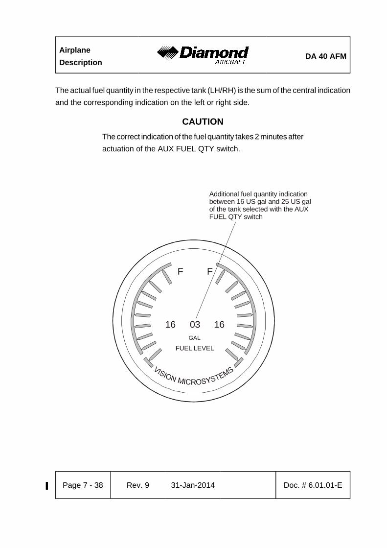
Airplane
DescriptionDA 40 AFM
Page 7 - 38 Rev. 9% 31-Jan-2014% Doc. # 6.01.01-E
F F
16 03 16GAL
FUEL LEVEL
Additional fuel quantity indicationbetween 16 US gal and 25 US galof the tank selected with the AUXFUEL QTY switch
The actual fuel quantity in the respective tank (LH/RH) is the sum of the central indication
and the corresponding indication on the left or right side.
CAUTION
The correct indication of the fuel quantity takes 2 minutes after
actuation of the AUX FUEL QTY switch.

DA 40 AFMAirplane
Description
Doc. # 6.01.01-E Rev. 9% 31-Jan-2014% Page 7 - 39
Fuel Quantity Measuring Device
The fuel quantity measuring device allows the fuel quantity in the tank to be determined
during the pre-flight inspection. It functions according to the principle of communicating
containers. The fuel quantity measuring device has a recess which fits the airfoil of the
wing. With this recess the device is held against the stall strip at the leading edge of the
wing. The exact position is marked by a bore in the stall strip. Then the metal connector
is pressed against the drain of the tank. The amount of fuel in the tank can now be read
off from the vertical ascending pipe.
For a correct indication the airplane must be placed on a horizontal ground and the fuel
filler must have been opened before.
The designated place for the fuel quantity measuring device is the bag on the rear side
of the pilot’s seat.
CAUTION
Different fuel measuring devices are used for the standard
tank and the long range tank. The use of the wrong device
results in a wrong indication.

Airplane
DescriptionDA 40 AFM
Page 7 - 40 Rev. 9% 31-Jan-2014% Doc. # 6.01.01-E
a )
Stan-
dard Tank b) Long Range Tank
20
19
18
17
16
15
14
13
12
11
10
9
8
7
6
5
4
3
2
1
aero
pla
ne
on
lev
el g
rou
nd
un
it in
u. s.
gallo
ns
unuseablefuel
no
t in
dic
ated
by
cockp
it i
nst
rum
ents
20
19
18
17
16
15
14
13
12
11
10
9
8
7
6
5
4
3
2
1
aero
pla
ne
on
lev
el g
rou
nd
un
it in
u. s.
gallo
ns
unuseablefuel
21
22
23
24
25
Diamond
AIRCRAFT
Indus
tries
Dwg. No.:
D41
-280
7-90-0
0

DA 40 AFMAirplane
Description
Doc. # 6.01.01-E Rev. 9% 31-Jan-2014% Page 7 - 41
Sim
plif
ied
wir
ing
dia
gra
m f
or
seri
al n
um
ber
s w
ith
ou
t E
ssen
tial
Bu
s
7.11 ELECTRICAL SYSTEM
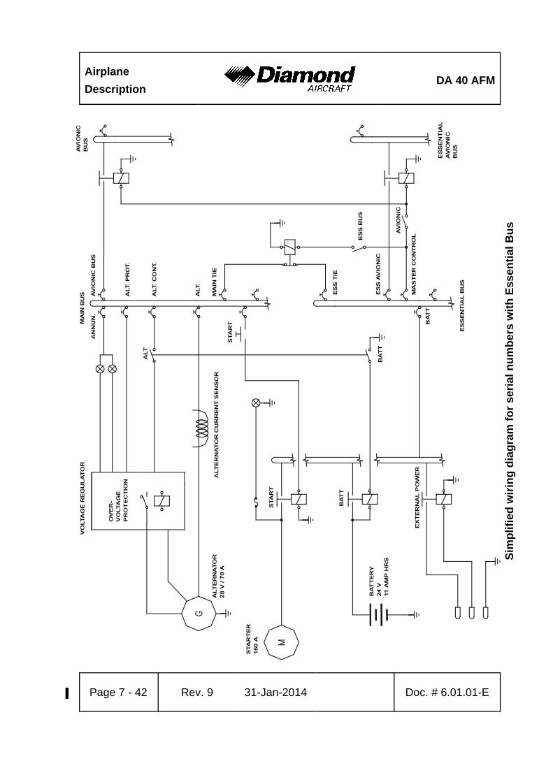
Airplane
DescriptionDA 40 AFM
Page 7 - 42 Rev. 9% 31-Jan-2014% Doc. # 6.01.01-E
Sim
plif
ied
wir
ing
dia
gra
m f
or
seri
al n
um
ber
s w
ith
Ess
enti
al B
us
DA 40 AFMAirplane
Description
Doc. # 6.01.01-E Rev. 9% 31-Jan-2014% Page 7 - 43
7.11.1 GENERAL
The DA 40 has 28 Volt DC system, which can be sub-divided into:
- Power generation
- Storage
- Distribution
- Consumers
Power Generation
The 70 Ampère alternator (generator) is mounted on the front of the engine. It is driven
by a V-belt, and charges the battery. In the event of alternator failure, the battery provides
the system with electrical energy. Given the provision of these two independent sources
of electrical power, the complete failure of the electrical system is extremely unlikely.
Storage
Power is stored in a lead-acid battery which is mounted in the right-hand side of the engine
compartment. It has a capacity of 10 Ampère-hour or more, depending on the battery
type. The battery is connected to the airplane electrical system via the main (70 Ampère)
circuit breaker.
In addition, a non-rechargeable dry battery or a lithium battery pack is installed in the IFR
model as a further source of power for the attitude gyro (artificial horizon) and the flood
light. When the emergency switch is set to ON, these two systems are supplied with power
for 1 hour and 30 minutes, independent of all other electrical consumers.
Distribution
Electrical power is distributed via the main bus and, if installed, the essential bus.

Airplane
DescriptionDA 40 AFM
Page 7 - 44 Rev. 9% 31-Jan-2014% Doc. # 6.01.01-E
Master Switch (ALT/BAT)
The Master switch is divided into a Master switch (ALT) on the left and a Master switch
(BAT) on the right. Both switches together are known as the Master switch (ALT/BAT).
Consumers
The individual consumers (e.g. radio, electrical fuel pump, position lights, etc.) are
connected to the main bus via automatic circuit breakers.
Designations and abbreviations used to identify the circuit breakers are explained in
Section 1.5 - DEFINITIONS AND ABBREVIATIONS.
Ignition
The basic version of the DA 40 is equipped with the electric start boost system
SlickSTART. This system improves the start characteristics by delivering more spark
energy during the engine start sequence. After engine starting the ignition is controlled
by the conventional retard breaker magneto system.
As an option, the LASAR electronic ignition control unit can be installed instead of the
SlickSTART system. This unit measures manifold pressure and RPM and uses these
parameters to optimize the ignition timing. This provides for smooth engine running and
improved starting behavior. If the electronic ignition control is not in operation, the status
light for the ignition illuminates and the conventional magneto ignition takes over the
ignition control. Also, during operation of the engine on only one magneto, for example
during the magneto check, the ignition is not controlled electronically and the status light
for the ignition should illuminate. For engine restart in flight without the electronic ignition
control being operative an engine speed of more than 500 RPM is necessary. The magneto
ignition is independent of the electrical network, therefore providing safe engine operation
even in the event of a power failure.
DA 40 AFMAirplane
Description
Doc. # 6.01.01-E Rev. 9% 31-Jan-2014% Page 7 - 45
Voltmeter
The voltmeter displays the potential on the main bus. If the alternator is operating, the
alternator voltage is shown, otherwise it is that provided by the battery.
Ammeter
The ammeter displays the current with which the alternator is being loaded.
Landing and Taxi Lights
Landing and taxi lights are built into the left wing, and are each operated by means of
a switch (LANDING, TAXI) on the row of switches on the instrument panel.
Position and Strobe Lights
Combined position and strobe lights (anti collision lights) are installed on both wing tips.
Each system is operated by a switch (POSITION, STROBE) on the row of switches on
the instrument panel.
Flood Light
A two-dimensional light emitter is mounted above the instrument panel. It illuminates the
instrument panel as well as all levers, switches, etc. With a rotary button (FLOOD) in the
left-hand section of the instrument panel the flood light is switched on and its brightness
is adjusted.
Instrument Lighting
With a rotary button (INSTRUMENT) in the left-hand section of the instrument panel the
internal lighting of the instruments is switched on and its brightness is adjusted.

Airplane
DescriptionDA 40 AFM
Page 7 - 46 Rev. 9% 31-Jan-2014% Doc. # 6.01.01-E
Pitot Heating
The Pitot probe, which provides measurement for the Pitot-static system, is electrically
heated. The heating is activated with a switch (PITOT) on the row of switches on the
instrument panel. The temperature is automatically kept constant by means of a thermal
switch on the Pitot probe, and as an additional safety measure a thermal fuse is built in.
If this thermal fuse is activated, the Pitot heating can no longer be switched on, and the
Pitot heating caution will be displayed. In this case the system should be serviced.
NOTE
The Pitot heating caution will also be displayed whenever the
Pitot heating system is switched OFF.
DA 40 AFMAirplane
Description
Doc. # 6.01.01-E Rev. 9% 31-Jan-2014% Page 7 - 47
7.11.2 DAI ANNUNCIATOR PANEL
(WARNING, CAUTION AND STATUS LIGHTS)
There are two variants of the annunciator panel ('DAI' and 'White Wire'). The 'DAI' variant,
which is described below, can be identified by the lights in the shape of a square.
Testing the Annunciator Panel
In the process of the pre-flight check the lights of the annunciator panel must be checked
by operating the test switch. This is to check that the lights have not failed. All lights must
be serviceable.
Alternator Warning Light (ALT)
The alternator warning light illuminates on alternator failure. The only remaining source
of electrical power is the battery. The color is red.
The procedure to be followed upon alternator warning is given in 3.7.2 - FAILURES IN
THE ELECTRICAL SYSTEM.
Low Voltage Caution Light (VOLT)
This caution light illuminates when the on-board voltage drops below 24 Volts. It goes
out again when the voltage exceeds 25 Volts. The color is amber.
The procedure to be followed upon low voltage caution is given in 4B.3 - FAILURES IN
THE ELECTRICAL SYSTEM.

Airplane
DescriptionDA 40 AFM
Page 7 - 48 Rev. 9% 31-Jan-2014% Doc. # 6.01.01-E
Fuel Pressure Warning Light (FUEL PR)
The fuel pressure warning light illuminates when the fuel pressure drops below 14 PSI.
The color is red.
Low Fuel Caution Lights (L FUEL and R FUEL)
Each tank has its own caution light. It starts to flash when the fuel quantity becomes low,
and illuminates permanently when the quantity of usable fuel in the respective tank drops
below 3 US gal (±1 US gal). The indication is calibrated for straight and level flight. The
light may illuminate during turns which are flown with slip, or while taxiing in curves. The
color is amber.
Oil Pressure Warning Light (OIL PR)
The oil pressure warning light illuminates when the oil pressure drops below 25 PSI. The
color is red.
The procedure to be followed upon oil pressure warning is given in 3.2.3 - ENGINE
PROBLEMS IN FLIGHT.
Door Warning Light (DOOR)
The door warning light illuminates when the front canopy and/or the rear door is not closed
and locked. The color is red.
The procedure to be followed upon door warning is given in 3.7.4 - DOOR-WARNING
LIGHT ON.

DA 40 AFMAirplane
Description
Doc. # 6.01.01-E Rev. 9% 31-Jan-2014% Page 7 - 49
Status Light for the Ignition (IGN)
This light is only used when the electronic ignition control unit is installed.
The status light for the ignition illuminates when the electronic ignition control is not
operating. In this case the conventional magneto ignition will be in use. The color is white.
The procedure to be followed upon illumination of the ignition status light is given in
4B.3 - FAILURES IN THE ELECTRICAL SYSTEM.
Starter Warning Light (START)
The starter warning light illuminates when the starter is being operated or when the
connection between the starter motor and the engine has not been broken. This occurs
when the pinion of the starter motor remains engaged with the propeller flywheel. The
color is red.
The procedure to be followed upon starter warning is given in 3.7.2 - FAILURES IN THE
ELECTRICAL SYSTEM.
Pitot Heating Caution Light (PITOT)
The Pitot heating caution light is illuminated when the Pitot heating is not switched on,
or when there is a failure of the Pitot heating system. The color is amber.
Prolonged operation of the Pitot heating on the ground can also cause the Pitot heating
caution light to illuminate. In this case it indicates the activation of the thermal switch, which
prevents overheating of the Pitot heating system on the ground. This is a normal function
of the system. After a cooling period, the heating system will be switched on again
automatically.
Airplane
DescriptionDA 40 AFM
Page 7 - 50 Rev. 9% 31-Jan-2014% Doc. # 6.01.01-E
7.11.3 WHITE WIRE ANNUNCIATOR PANEL
(WARNING, CAUTION AND STATUS LIGHTS)
There are two variants of the annunciator panel ('DAI' and 'White Wire'). The 'White Wire'
variant, which is described below, can be identified by the flat front panel and the 'White
Wire' logo on the display in the upper left corner.
Testing the Annunciator Panel
In the process of the pre-flight check, proper functioning of the annunciator panel must
be verified. This functional check is automatically started after switching the battery master
switch ON. All lights are flashed, and the aural alert is muted. By pressing the
'acknowledge' button, the lights are extinguished, and a momentary aural alert is sounded.
This test verifies functionality of the microprocessor, the lights, and the aural signal.
The pilot may initiate additional system tests by holding the 'acknowledge' button for
2 seconds. All lights will begin flashing, and the aural alert will sound continuously.
Warning Messages
A warning is indicated by a continuous aural alert (sounded in the airplane's intercom
system), flashing of the red WARNING light, and flashing of the red warning light
associated with the affected system.
By pressing the 'acknowledge' button, which is now illuminated green, the aural alert will
be terminated, and the WARNING light will be extinguished. The warning light associated
with the affected system will change from flashing to solid illumination.

DA 40 AFMAirplane
Description
Doc. # 6.01.01-E Rev. 9% 31-Jan-2014% Page 7 - 51
Caution Messages
A caution is indicated by a momentary aural alert (sounded in the airplane's intercom
system), flashing of the amber CAUTION light, and flashing of the amber caution light
associated with the affected system.
By pressing the 'acknowledge' button, which is now illuminated green, the CAUTION light
will be extinguished. The caution light associated with the affected system will change
from flashing to solid illumination.
The LOW FUEL caution message is displayed in a slightly different manner (extended
functionality), which is described below.
Alternator Warning Message (ALTERNATOR)
The alternator warning message is displayed on alternator failure. The only remaining
source of electrical power is the battery.
The procedure to be followed upon alternator warning is given in 3.7.2 - FAILURES IN
THE ELECTRICAL SYSTEM.
Low Voltage Caution Message (LOW VOLTS)
The low voltage caution message is displayed when the on-board voltage drops below
24 Volts. It is terminated when the voltage exceeds 25 Volts again.
The procedure to be followed upon low voltage caution is given in 4B.3 - FAILURES IN
THE ELECTRICAL SYSTEM.

Airplane
DescriptionDA 40 AFM
Page 7 - 52 Rev. 9% 31-Jan-2014% Doc. # 6.01.01-E
Fuel Pressure Warning Message (FUEL PRESS)
The fuel pressure warning message is displayed when the fuel pressure drops below
14 PSI.
Low Fuel Caution Message (LOW FUEL)
As soon as the amount of usable fuel in one tank is less than 3 US gal (±1 US gal), a
caution message is displayed in the usual manner (momentary aural alert, flashing
CAUTION light, flashing LOW FUEL caution light). Termination of the message is also
done as usual ('acknowledge', CAUTION light is extinguished, LOW FUEL caution light
changes to solid illumination).
As soon as the amount of usable fuel in the second tank is also less than 3 US gal
(±1 US gal), a caution message is displayed in a different manner. A continuous aural
alert is sounded in the airplane's intercom system, the amber CAUTION light is flashed,
and the amber LOW FUEL caution light is flashed.
By pressing the 'acknowledge' button, which is now illuminated green, the aural alert will
be terminated, and the CAUTION light will be extinguished. The LOW FUEL caution light
will continue to be flashed.
The indication is calibrated for straight and level flight. The caution message may be
triggered during turns which are flown with slip, or while taxiing in curves.
Oil Pressure Warning Message (OIL PRESS)
The oil pressure warning message is displayed when the oil pressure drops below 25 PSI.
The procedure to be followed upon oil pressure warning is given in 3.2.3 - ENGINE
PROBLEMS IN FLIGHT.
DA 40 AFMAirplane
Description
Doc. # 6.01.01-E Rev. 9% 31-Jan-2014% Page 7 - 53
Door Warning Message (DOORS)
The door warning message is displayed when the front canopy and/or the rear door is
not closed and locked.
The procedure to be followed upon door warning is given in 3.7.4 - DOOR-WARNING
LIGHT ON.
Status Light for the Ignition (IGN)
This light is only used when the electronic ignition control unit is installed.
The status light for the ignition is illuminated when the electronic ignition control is not
operating. In this case the conventional magneto ignition will be in use. The color is white.
The WARNING light, the CAUTION light, and the aural alert will not be activated.
The procedure to be followed upon illumination of the ignition status light is given in
4B.3 - FAILURES IN THE ELECTRICAL SYSTEM.
Starter Warning Message (START)
The starter warning message is displayed when the connection between the starter motor
and the engine has not been broken. This occurs when the pinion of the starter motor
remains engaged with the propeller flywheel.
Furthermore, the START warning light is illuminated continuously as long as the starter
is being operated. In this case the WARNING light and the aural alert will not be activated.
The procedure to be followed upon starter warning is given in 3.7.2 - FAILURES IN THE
ELECTRICAL SYSTEM.

Airplane
DescriptionDA 40 AFM
Page 7 - 54 Rev. 9% 31-Jan-2014% Doc. # 6.01.01-E
Pitot Heating Caution Message (PITOT)
The Pitot heating caution message is displayed when the Pitot heating is not switched
on, or when there is a failure of the Pitot heating system.
Prolonged operation of the Pitot heating on the ground can also cause the Pitot heating
caution message to be displayed. In this case it indicates the activation of the thermal
switch, which prevents overheating of the Pitot heating system on the ground. This is a
normal function of the system. After a cooling period, the heating system will be switched
on again automatically.
Trim Failure Warning Message (TRIM FAIL)
The White Wire annunciator panel is prepared for the installation of an autopilot in the
DA 40. When the autopilot is installed and ready for operation, this warning message
indicates a failure of the automatic trim system of the autopilot. For further details, refer
to the Supplement to the AFM for the autopilot (if installed).
Unused Lights
The White Wire annunciator panel has two lights for possible future use. These lights are
currently unused.
DA 40 AFMAirplane
Description
Doc. # 6.01.01-E Rev. 9% 31-Jan-2014% Page 7 - 55
7.12 PITOT-STATIC SYSTEM
Total pressure is measured at the leading edge of a Pitot probe under the left wing. Static
pressure is measured at two orifices at lower and rear edges of the same probe. To protect
against dirt and condensation there are filters in the system, which are accessible from
the wing root. The Pitot probe is electrically heated.
In addition, some serial numbers have an alternate static valve installed on the underside
of the instrument panel. With this valve, the static pressure in the cabin can be used as
static pressure source in the event of a failure of the Pitot-static system.
If an autopilot system is installed, additional static sources may be installed (OÄM 40-267).
7.13 STALL WARNING
If airspeed drops below approximately 10 to minimum 5 knots above the stalling speed,
the stall warning horn, located in the instrument panel, will sound. The horn becomes
progressively louder the closer one gets to stalling speed. Suction at an orifice on the
left wing leading edge activates the horn via a hose. The orifice for the stall warning in
the left wing is marked by a red ring.
7.14 AVIONICS
The radio and navigation equipment is located in the central part of the instrument panel.
A transmit switch for the radio is mounted on the end of each control stick. There are
connection facilities for up to 4 headsets between the front seats.

Airplane
DescriptionDA 40 AFM
Page 7 - 56 Rev. 9% 31-Jan-2014% Doc. # 6.01.01-E
7.15 CO-MONITOR (IF INSTALLED)
The airplane may be equipped with a CO detector (OÄM 40-253).
7.15.1 SELF TEST SEQUENCE
When power is applied to the CO detector, a self-test routine begins. The test checks
for functionality of the critical components such as the CO sensor, temperature sensor,
and the integrity of the total CO detector system.
The remote alert light will flash twice. Then the remote light will remain OFF until there
is another CO alert or until a failure of the unit occurs.
7.15.2 IN-FLIGHT CO ALARM
If the CO detector visual alert annunciator illuminates in flight, press the TEST/RESET
button.
If the alert continues with the remote light staying ON, proceed with the emergency
procedure 3.7.3 - SUSPICION OF CARBON MONOXIDE CONTAMINATION IN THE
CABIN.
NOTE
The remote light will stay on until the CO level goes below
50 PPM.

DA 40 AFMAirplane
Description
Doc. # 6.01.01-E Rev. 9% 31-Jan-2014% Page 7 - 57
7.15.3 UNIT FAILURE INDICATION
A failure of the CO sensor, temperature sensor, or the micro-controller will result in the
following failure indications:
The remote light will flash at an approximately rate of one flash each four seconds until
the failure is cleared or power is removed from the unit.

Airplane
DescriptionDA 40 AFM
Page 7 - 58 Rev. 9% 31-Jan-2014% Doc. # 6.01.01-E
Intentionally left blank.%
Related Documents