Electrical Machines II 6 Synchronous motor 6.1 Principle of operation In order to understand the principle of operation of a synchronous motor, let us examine what happens if we connect the armature winding (laid out in the stator) of a 3-phase synchronous machine to a suitable balanced 3-phase source and the field winding to a D.C source of appropriate voltage. The current flowing through the field coils will set up sta- tionary magnetic poles of alternate North and South. ( for convenience let us assume a salient pole rotor, as shown in Fig. 50). On the other hand, the 3-phase currents flowing in the armature winding produce a rotating magnetic field rotating at synchronous speed. In other words there will be moving North and South poles established in the stator due to the 3-phase currents i.e at any location in the stator there will be a North pole at some instant of time and it will become a South pole after a time period corresponding to half a cycle. (after a time = 2 1 f , where f = frequency of the supply). Let us assume that the stationary South pole in the rotor is aligned with the North pole in the stator moving in clockwise direction at a particular instant of time, as shown in Fig. 50. These two poles get attracted and N S Direction of rotation of stator poles S N N T S Stationary rotor poles Figure 50: Force of attraction between stator poles and rotor poles - resulting in production of torque in clockwise direction try to maintain this alignment ( as per lenz’s law) and hence the rotor pole tries to follow the stator pole as the conditions are suitable for the production of torque in the clockwise direction. However the rotor cannot move instantaneously due to its mechanical inertia, and so it needs sometime to move. In the mean time, the stator pole would quickly (a time duration corresponding to half a cycle) change its polarity and becomes a South pole. So the force of attraction will no longer be present and instead the like poles experience a force

Welcome message from author
This document is posted to help you gain knowledge. Please leave a comment to let me know what you think about it! Share it to your friends and learn new things together.
Transcript

Electrical Machines II
6 Synchronous motor
6.1 Principle of operation
In order to understand the principle of operation of a synchronous motor, let us examinewhat happens if we connect the armature winding (laid out in the stator) of a 3-phasesynchronous machine to a suitable balanced 3-phase source and the field winding to a D.Csource of appropriate voltage. The current flowing through the field coils will set up sta-tionary magnetic poles of alternate North and South. ( for convenience let us assume asalient pole rotor, as shown in Fig. 50). On the other hand, the 3-phase currents flowing inthe armature winding produce a rotating magnetic field rotating at synchronous speed. Inother words there will be moving North and South poles established in the stator due to the3-phase currents i.e at any location in the stator there will be a North pole at some instant oftime and it will become a South pole after a time period corresponding to half a cycle. (after
a time = 21
f , where f = frequency of the supply). Let us assume that the stationary Southpole in the rotor is aligned with the North pole in the stator moving in clockwise direction at aparticular instant of time, as shown in Fig. 50. These two poles get attracted and
N
S
Direction of rotation of stator poles
S N
NT
S Stationaryrotor poles
Figure 50: Force of attraction between stator poles and rotor poles - resulting inproduction of torque in clockwise direction
try to maintain this alignment ( as per lenz’s law) and hence the rotor pole tries to follow thestator pole as the conditions are suitable for the production of torque in the clockwisedirection. However the rotor cannot move instantaneously due to its mechanical inertia, andso it needs sometime to move. In the mean time, the stator pole would quickly (a timeduration corresponding to half a cycle) change its polarity and becomes a South pole. Sothe force of attraction will no longer be present and instead the like poles experience a force

of repulsion as shown in Fig. 51. In other words, the conditions are now suitable for the
Direction of rotation of stator poles
N S
TN
S
N
S Stationaryrotor poles
Figure 51: Force of repulsion between stator poles and rotor poles - resulting inproduction of torque in anticlockwise direction
production of torque in the anticlockwise direction. Even this condition will not last longer asthe stator pole would again change to North pole after a time of 2
1f . Thus the rotor will
experience an alternating force which tries to move it clockwise and anticlockwise at twicethe frequency of the supply, i.e. at intervals corresponding to 2
1f seconds. As this duration is
quite small compared to the mechanical time constant of the rotor, the rotor cannot respondand move in any direction. The rotor continues to be stationary only.
On the contrary if the rotor is brought to near synchronous speed by someexternal means say a small motor (known as pony motor-which could be a D.C or ACin-duction rotor) mounted on the same shaft as that of the rotor, the rotor poles getlocked to the unlike poles in the stator and the rotor continues to run at the synchronousspeed even if the supply to the pony motor is disconnected.
Thus the synchronous rotor cannot start rotating on its own or usually we say thatthe synchronous rotor has no starting torque. So, some special provision has to be made eitherinside the machine or outside of the machine so that the rotor is brought to near about itssynchronous speed. At that time, if the armature is supplied with electrical power, the rotor canpull into step and continue to operate at its synchronous speed. Some of the commonly usedmethods for starting synchronous rotor are described in the following section.
6.2 Methods of starting synchronous motor
Basically there are three methods that are used to start a synchronous motor:
• To reduce the speed of the rotating magnetic field of the stator to a low enoughvalue that the rotor can easily accelerate and lock in with it during one half-cycle ofthe rotating magnetic field’s rotation. This is done by reducing the frequency of theapplied electric power. This method is usually followed in the case of inverter-fedsynchronous motor operating under variable speed drive applications.
• To use an external prime mover to accelerate the rotor of synchronous motor near toits synchronous speed and then supply the rotor as well as stator. Ofcourse careshould be taken to ensure that the direction of rotation of the rotor as well as that ofthe rotating magnetic field of the stator are the same. This method is usually followedin the laboratory- the synchronous machine is started as a generator and is thenconnected to the supply mains by following the synchronization or parallelingprocedure. Then the power supply to the prime mover is disconnected so that thesynchronous machine will continue to operate as a motor.
• To use damper windings or amortisseur windings if these are provided in the ma-chine. The damper windings or amortisseur windings are provided in most of thelarge synchronous motors in order to nullify the oscillations of the rotor wheneverthe synchronous machine is subjected to a periodically varying load.
Each of these methods of starting a synchronous motor are described below in detail.
6.2.1 Motor Starting by Reducing the supply Frequency
If the rotating magnetic field of the stator in a synchronous motor rotates at a lowenough speed, there will be no problem for the rotor to accelerate and to lock in with thestator’s magnetic field. The speed of the stator magnetic field can then be increased toits rated op-erating speed by gradually increasing the supply frequency f up to itsnormal 50- or 60-Hz value.This approach to starting of synchronous motors makes a lot of sense, but there is a bigproblem: Where from can we get the variable frequency supply? The usual power supplysystems generally regulate the frequency to be 50 or 60 Hz as the case may be. However,variable-frequency voltage source can be obtained from a dedicated generator only in the

olden days and such a situation was obviously impractical except for very unusual orspecial drive applications.But the present day solid state power converters o er an easy solution to this. We nowffhave the rectifier- inverter and cycloconverters, which can be used to convert a constant fre-quency AC supply to a variable frequency AC supply. With the development of such modernsolid-state variable-frequency drive packages, it is thus possible to continuously control thefrequency of the supply connected to the synchronous motor all the way from a fraction of ahertz up to and even above the normal rated frequency. If such a variable-frequency driveunit is included in a motor-control circuit to achieve speed control, then starting thesynchronous motor is very easy-simply adjust the frequency to a very low value for starting,and then raise it up to the desired operating frequency for normal running.When a synchronous motor is operated at a speed lower than the rated speed, its internal
generated voltage (usually called the counter EMF) EA = K φω will be smaller than normal.As such the terminal voltage applied to the motor must be reduced proportionally with thefrequency in order to keep the stator current within the rated value. Generally, the voltage inany variable-frequency power supply varies roughly linearly with the output frequency.
6.2.2 Motor Starting with an External Motor
The second method of starting a synchronous motor is to attach an external starting motor(pony motor) to it and bring the synchronous machine to near about its rated speed (but notexactly equal to it, as the synchronization process may fail to indicate the point of closure ofthe main switch connecting the synchronous machine to the supply system) with the ponymotor. Then the output of the synchronous machine can be synchronised or paralleled withits power supply system as a generator, and the pony motor can be detached from the shaftof the machine or the supply to the pony motor can be disconnected. Once the pony motor
is turned OFF, the shaft of the machine slows down, the speed of the rotor magnetic field BR
falls behind Bnet, momentarily and the synchronous machine continues to operate as amotor. As soon as it begins to operates as a motor the synchronous motor can be loaded inthe usual manner just like any motor.
This whole procedure is not as cumbersome as it sounds, since many synchronous mo-tors are parts of motor-generator sets, and the synchronous machine in the motor-generator setmay be started with the other machine serving as the starting motor. More over, the startingmotor is required to overcome only the mechanical inertia of the synchronous ma-chine withoutany mechanical load ( load is attached only after the synchronous machine is

paralleled to the power supply system). Since only the motor’s inertia must beovercome, the starting motor can have a much smaller rating than the synchronousmotor it is going to start. Generally most of the large synchronous motors havebrushless excitation systems mounted on their shafts. It is then possible to use theseexciters as the starting motors. For many medium-size to large synchronous motors, anexternal starting motor or starting by using the exciter may be the only possible solution,because the power systems they are tied to may not be able to handle the startingcurrents needed to use the damper (amortisseur) winding approach described next.
6.2.3 Motor Starting by Using damper (Amortisseur) Winding
As already mentioned earlier most of the large synchronous motors are provided withdamper windings, in order to nullify the oscillations of the rotor whenever thesynchronous machine is subjected to a periodically varying load. Damper windings arespecial bars laid into slots cut in the pole face of a synchronous machine and thenshorted out on each end by a large shorting ring, similar to the squirrel cage rotor bars.A pole face with a set of damper wind-ings is shown in Figure..
When the stator of such a synchronous machine is connected to the 3-Phase AC sup-ply, the machine starts as a 3-Phase induction machine due to the presence of the damper bars,just like a squirrel cage induction motor. Just as in the case of a 3-Phase squirrel cage inductionmotor, the applied voltage must be suitably reduced so as to limit the starting cur-rent to thesafe rated value. Once the motor picks up to a speed near about its synchronous speed, the DCsupply to its field winding is connected and the synchronous motor pulls into step i.e. itcontinues to operate as a Synchronous motor running at its synchronous speed.
6.3 Behavior of a synchronous motor
The behavior of a synchronous motor can be predicted by considering its equivalentcircuit on similar lines to that of a synchronous generator as described below.

6.3.1 Equivalent circuit model and phasor diagram of a synchronous motor
The equivalent-circuit model for one armature phase of a cylindrical rotor three phasesyn-chronous motor is shown in Fig. 52 exactly similar to that of a synchronousgenerator except that the current flows in to the armature from the supply. All values aregiven per phase. Applying Kirchho ’s voltage law to Fig. 52,ff
jXl jXas
IaRa
If
jXs R
DCVT Ef source
Field winding
Figure 52: Equivalent-circuit model for one phase of a synchronous motor armature
VT = IaRa + jIaXl + jIaXas + Ef (58)
Combining reactances, we have
Xs = Xl + Xas (59)
Substituting Eqn. 59 in Eqn. 58
VT = Ef + Ia(Ra + jXs)
or VT = Ef + IaZs
where:Ra = armature resistance (Ω/phase)Xl = armature leakage reactance (Ω/phase)Xs = synchronous reactance (Ω/phase)Zs = synchronous impedance (Ω/phase)VT = applied voltage/phase (V)Ia = armature current/phase(A)
(60)
(61)

jIaxs
Iazs
- ) VTφ
i
(90
IaRa δ
IaZs
φijIaxs
Ef
Ia
IaRa
Figure 53: Phasor diagram corresponding to the equivalent-circuit model
A phasor diagram shown in Fig. 53, illustrates the method of determining thecounter EMF which is obtained from the phasor equation;
Ef = VT − IaZs
The phase angle δ between the terminal voltage VT and the excitation voltage Ef
in Fig. 53 is usually termed the torque angle. The torque angle is also called the loadangle or power angle.
6.3.2 Synchronous-motor power equation
Except for very small machines, the armature resistance of a synchronous motor is relativelyinsignificant compared to its synchronous reactance, so that Eqn. 61 to be approximated to
VT = Ef + jIaXs (62)
The equivalent-circuit and phasor diagram corresponding to this relation are shownin Fig. 54 and Fig. 55. These are normally used for analyzing the behavior of a synchronous
motor, due to changes in load and/or changes in field excitation.From this phasor diagram, we have,
IaXs cos θi = −Ef sin δ (63)
Multiplying through by VT and rearranging terms we have,
VT Ia cos φi = −VT Ef sin δ (64)Xs
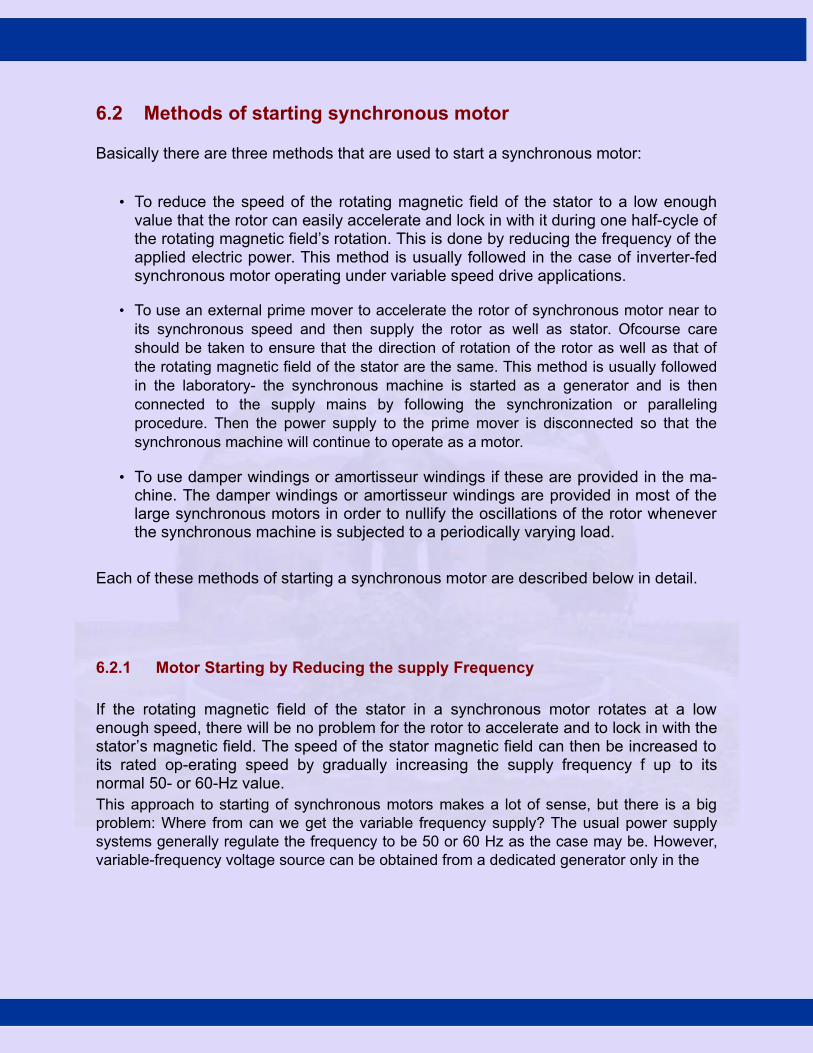
Since the left side of Eqn. 64 is an expression for active power input and as thewinding resistance is assumed to be negligible this power input will also represent theelectromagnetic power developed, per phase, by the synchronous motor. Thus,
Pin,ph = VT Ia cos φi (65)
or
Pin,ph
= −VT Ef sin δ (66)Xs
Thus, for a three-phase synchronous motor,
Pin = 3 ∗ VT Ia cos φi (67)
or
Pin = 3 ∗ −VT Ef sin δ (68)Xs
Eqn. 66, called the synchronous-machine power equation, expresses the electromag-netic power developed per phase by a cylindrical-rotor motor, in terms of itsexcitation volt-age and power angle. Assuming a constant source voltage and constantsupply frequency, Eqn. 65 and Eqn. 66 may be expressed as proportionalities that arevery useful for analyzing the behavior of a synchronous-motor:
P ∝ Ia cos θ (69)
P ∝ Ef sin δ (70)

Ia jXs
To AC VT Ef
source
Figure 54: Equivalent-circuit of a synchronous-motor, assuming armature resistance is neg-ligible
VT
δ
Efsinδ φiφi jIaXs
Ia
IaXscosφi
Ef
Figure 55: Phasor diagram model for a synchronous-motor, assuming armature resistance is negligible

6.3.3 E ect of changes in load on armature current, power angle, and powerfffactor of synchronous motor
The e ects of changes in mechanical or shaft load on armature current, power angle, andffpower factor can be seen from the phasor diagram shown in Fig. 56; As already stated, theapplied stator voltage, frequency, and field excitation are assumed, constant. The initial loadconditions, are represented by the thick lines. The e ect of increasing the shaft load tofftwice its initial value are represented by the light lines indicating the new steady stateconditions. These are drawn in accordance with Eqn. 69 and Eqn. 70, when the shaft loadis doubled both Ia cos φi and Ef sin δ are doubled. While redrawing the phasor diagrams to
show new steady-state conditions, the line of action of the new jIaXs phasor must be
perpendicular to the new Ia phasor. Furthermore, as shown in Fig. 56, if the excitation is not
changed, increasing the shaft load causes the locus of the E f phasor to follow a circular arc,thereby increasing its phase angle with increasing shaft load. Note also that an increase inshaft load is also accompanied by a decrease in φi; resulting in an increase in power factor.
As additional load is placed on the machine, the rotor continues to increase its angle
2(Ia1cosφi1)
Ia1cosφi1
VT
δ2 δ1 sφi1
X
X
sa1
φi2 Ef1jI
a2
Ia1 Ia2 jI
Ef 2
phasorf
of
E
Locus
Ef1sinδ1
2(Ef1sinδ1)
Figure 56: Phasor diagram showing e ect of changes in shaft load on armature current,ffpower angle and power factor of a synchronous motor
of lag relative to the rotating magnetic field, thereby increasing both the angle of lag ofthe counter EMF phasor and the magnitude of the stator current. It is interesting to notethat during all this load variation, however, except for the duration of transient conditions
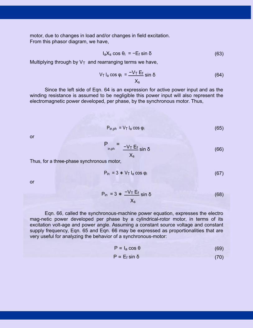
whereby the rotor assumes a new position in relation to the rotating magnetic field, theaverage speed of the machine does not change. As the load is being increased, a finalpoint is reached at which a further increase in δ fails to cause a corresponding increasein motor torque, and the rotor pulls out of synchronism. In fact as stated earlier, the rotorpoles at this point, will fall behind the stator poles such that they now come under theinfluence of like poles and the force of attraction no longer exists. Thus, the point ofmaximum torque occurs at a power angle of approximately 90 ◦ for a cylindrical-rotormachine, as is indicated by Eqn. 68. This maximum value of torque that causes asynchronous motor to pull out of synchronism is called the pull-out torque. In actualpractice, the motor will never be operated at power angles close to 90 ◦ as armaturecurrent will be many times its rated value at this load.
6.3.4 E ect of changes in field excitation on synchronous motor performanceff
Intuitively we can expect that increasing the strength of the magnets will increase the mag-neticattraction, and thereby cause the rotor magnets to have a closer alignment with thecorresponding opposite poles of the rotating magnetic poles of the stator. This will obvi-ouslyresult in a smaller power angle. This fact can also be seen in Eqn. 68. When the shaft load is
assumed to be constant, the steady-state value of Ef sin δ must also be constant. An increase in
Ef will cause a transient increase in Ef sin δ, and the rotor will accelerate. As the rotor changes
its angular position, δ decreases until Ef sin δ has the same steady-state value as before, atwhich time the rotor is again operating at synchronous speed, as it should run only at thesynchronous speed. This change in angular position of the rotor magnets relative to the poles ofrotating magnetic field of the stator occurs in a fraction of a second.
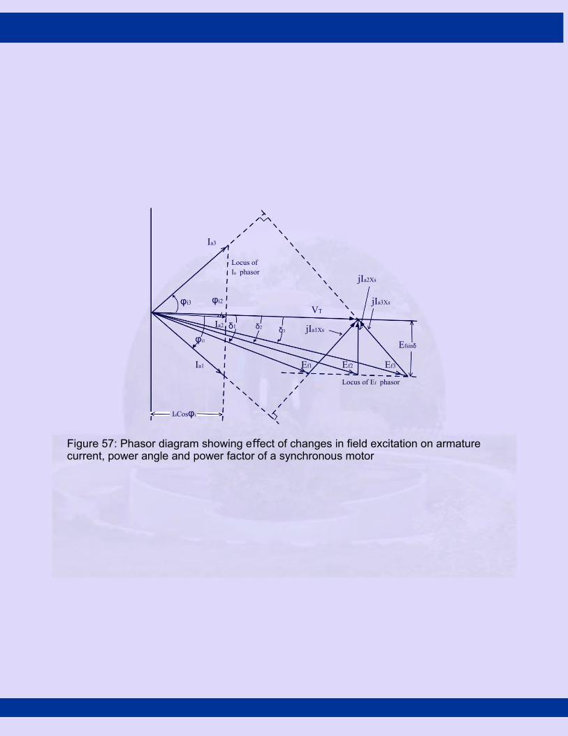
The e ect of changes in field excitation on armature current, power angle, andffpower factor of a synchronous motor operating with a constant shaft load, from aconstant voltage, constant frequency supply, is illustrated in Fig. 57. From Eqn. 69, wehave for a constant shaft load,
Ef 1 sin δ1 = Ef 2 sin δ2 = Ef 3 sin δ3 = Ef sin δ (71)
This is shown in Fig. 57, where the locus of the tip of the Ef phasor is a straight lineparallel to the VT phasor. Similarly, from Eqn. 69, for a constant shaft load,
Ia1 cos φi1 = Ia2 cos φi2 = Ia3 cos φi3 = Ia cos φi (72)
This is also shown in Fig. 57, where the locus of the tip of the Ia phasor is a line
Ia3
Locus ofIa phasor
jIa2Xs
φi3 φi2
VT
jIa3Xs
Ia2 δ1 δ2 δ3 jIa1Xs
φi1Efsinδ
Ia1 Ef1 Ef2 Ef3
Locus of Ef phasor
IaCosφi
Figure 57: Phasor diagram showing e ect of changes in field excitation on armature ffcurrent, power angle and power factor of a synchronous motor
perpendicular to the VT phasor.
Note that increasing the excitation from Ef 1 to Ef 3 in Fig. 57 caused the phase angle of the
current phasor with respect to the terminal voltage VT (and hence the power factor) to gofrom lagging to leading. The value of field excitation that results in unity power factor iscalled normal excitation. Excitation greater than normal is called over excitation, andexcitation less than normal is called under excitation. Furthermore, as indicated in Fig. 57,when operating in the overexcited mode, |Ef | > |VT |. In fact a synchronous motor operatingunder over excitation condition is sometimes called a synchronous condenser.
6.3.5 V curves
Curves of armature current vs. field current (or excitation voltage to a di erent scale)ffare called V curves, and are shown in Fig. 58 for typical values of synchronous motorloads. The curves are related to the phasor diagram in Fig. 57, and illustrate the e ectffof the variation of field excitation on armature current and power factor for typical shaftloads. It can be easily noted from these curves that an increase in shaft loads require anincrease in field excitation in order to maintain the power factor at unity.
The locus of the left most point of the V curves in Fig. 58 represents the stabilitylimit (δ = −90◦). Any reduction in excitation below the stability limit for a particular loadwill cause the rotor to pullout of synchronism.
The V curves shown in Fig. 58 can be determined experimentally in the laboratory byvarying If at a constant shaft load and noting Ia as If is varied. Alternatively the V curves shown
in Fig. 58 can be determined graphically by plotting |Ia|vs.|Ef | from a family of phasor diagramsas shown in Fig. 57, or from the following mathematical expression for the V curves
(IaXs)2
= V 2 + E2 − 2VT Ef cos δ (73)T f
= VT2 + Ef
2 − 2VT Ef p
1 − sin2 δ2 + E2 q
= V − 2 V 2 E2 − V 2E2 sin2 δT f Tf Tf
1.r
Ia = VT2 + Ef
2 − 2 VT2 Ef
2 − Xs2.Pin,ph
2(74)
Xs q

Eqn. 74 is based on the phasor diagram and the assumption that Ra is negligible. It is to benoted that instability will occur, if the developed torque is less than the shaft load plusfriction and windage losses, and the expression under the square root sign will be negative.
The family of V curves shown in Fig. 58 represent computer plots of Eqn. 74, by tak-ingthe data pertaining to a three-phase 10 hp synchronous motor i.e Vph = 230V and Xs =1.2Ω/phase.
Armature current Ia A/phase
160
140
120Stability limit
100
80
60
lagging40
power20 factor
0No
load
Unity
PF loadrated
150% loadrated
100%
ratedload
50%
Leadingpower factor
0 50 100 150 200 250
Excitation voltage Ef V/phase
Figure 58: Family of representative V curves for a synchronous motor
6.3.6 Synchronous-motor losses and e ciencyffi
The flow of power through a synchronous motor, from stator to rotor and then to shaftoutput, is shown in Fig. 59. As indicated in the power-flow diagram, the total power lossfor the motor is given by
Ploss
= P
scl +
P
core +
P
f cl +
P
f,w +
P
stray W
(75)where:Pscl= stator-copper lossPf cl = fie1d-copper.lossPcore = core loss

Indian Institute of Technology Madras

Pf,w = friction and windage lossPstray = stray load lossExcept for the transient conditions that occur when the field current is increased or de-creased (magnetic energy stored or released), the total energy supplied to the field coils isconstant and all of it is consumed as I 2R losses in the field winding. Just as in the case ofthe synchronous generator, the overall efficiency of a synchronous motor is given by
η =
Pshaf t
=
Pshaf t
(76)P
in +
P
f ieldP
shaf t +
P
loss
Generally, the nameplates of synchronous motors and manufacturers’specification sheets customarily provide the overall e ciency for rated load and fewffiload conditions only. Hence, only the total losses at these loads can be determined. Theseparation of losses into the components listed in Eqn. 75 needs a very involved testprocedure in the laboratory. However, a closer approximation of the mechanical powerdeveloped can be calculated by subtracting the copper losses of the armature and fieldwinding if these losses can be calculated. The shaft power can then be calculatedsubtracting the mechanical losses from the mechanical power developed.
Pin
PfieldPshaft
N
RotorS
Pgap
Pfcl
Pstray
Pscl Pcore Pf,w
Figure 59: Power flow diagram for a synchronous motor

Scanned by CamScanner

Scanned by CamScanner

Scanned by CamScanner

Scanned by CamScanner

Scanned by CamScanner

Scanned by CamScanner

Scanned by CamScanner

Scanned by CamScanner
Scanned by CamScanner

Scanned by CamScanner

Scanned by CamScanner
Scanned by CamScanner

Scanned by CamScanner

Scanned by CamScanner

Scanned by CamScanner

Scanned by CamScanner
Scanned by CamScanner

Scanned by CamScanner

Scanned by CamScanner

Scanned by CamScanner

Scanned by CamScanner
Scanned by CamScanner

Scanned by CamScanner
Scanned by CamScanner

Scanned by CamScanner

Scanned by CamScanner

Scanned by CamScanner

Scanned by CamScanner

Scanned by CamScanner

Scanned by CamScanner

Scanned by CamScanner

Scanned by CamScanner
Scanned by CamScanner

Scanned by CamScanner

Scanned by CamScanner

Scanned by CamScanner
Scanned by CamScanner
Scanned by CamScanner

Scanned by CamScanner

Scanned by CamScanner

Scanned by CamScanner

Scanned by CamScanner

Scanned by CamScanner
Scanned by CamScanner

Scanned by CamScanner
Scanned by CamScanner

Scanned by CamScanner

Scanned by CamScanner
Scanned by CamScanner

Scanned by CamScanner

Scanned by CamScanner

Scanned by CamScanner

Scanned by CamScanner
Scanned by CamScanner

Scanned by CamScanner
Scanned by CamScanner

Scanned by CamScanner

Scanned by CamScanner

Scanned by CamScanner

Scanned by CamScanner

Scanned by CamScanner

Scanned by CamScanner

Scanned by CamScanner

Scanned by CamScanner

Scanned by CamScanner

Scanned by CamScanner

Scanned by CamScanner

Scanned by CamScanner
Scanned by CamScanner

Scanned by CamScanner
Scanned by CamScanner
Scanned by CamScanner
Scanned by CamScanner

Scanned by CamScanner

Scanned by CamScanner
Scanned by CamScanner

Scanned by CamScanner

Scanned by CamScanner
Scanned by CamScanner
Scanned by CamScanner

Scanned by CamScanner

Scanned by CamScanner

Scanned by CamScanner
Scanned by CamScanner

Three Phase Induction Motor
Construction:
` The three phase induction motor is the most widely used electrical motor. Almost 80% ofthe mechanical power used by industries is provided by three phase induction motors because ofits simple and rugged construction, low cost, good operating characteristics, absence ofcommutator and good speed regulation. In three phase induction motor the power is transferredfrom stator to rotor winding through induction. The Induction motor is also called asynchronousmotor as it runs at a speed other than the synchronous speed. Like any other electrical motorinduction motor also have two main parts namely rotor and stator.
1. Stator: As its name indicates stator is a stationary part of induction motor. A statorwinding is placed in the stator of induction motor and the three phase supply is given toit.
2. Rotor: The rotor is a rotating part of induction motor. The rotor is connected to themechanical load through the shaft.
The rotor of the three phase induction motor are further classified as 1. Squirrel cage rotor,2. Slip ring rotor or wound rotor or phase wound rotor.
Depending upon the type of rotor construction used the three phase induction motor areclassified as:
1. Squirrel cage induction motor,2. Slip ring induction motor or wound induction motor or phase wound induction motor.
The construction of stator for both the kinds of three phase induction motor remains the sameand is discussed in brief in next paragraph. The other parts, which are required to complete theinduction motor, are:
1. Shaft for transmitting the torque to the load. This shaft is made up of steel.
2. Bearings for supporting the rotating shaft.
3. One of the problems with electrical motor is the production of heat during its rotation. Inorder to overcome this problem we need fan for cooling.
4. For receiving external electrical connection Terminal box is needed.
5. There is a small distance between rotor and stator which usually varies from 0.4 mm to 4mm. Such a distance is called air gap.
Types of Three Phase Induction MotorSquirrel cage three phase induction motor: The rotor of the squirrel cage three phase
induction motor is cylindrical in shape and have slots on its periphery. The slots are not madeparallel to each other but are bit skewed (skewing is not shown in the figure of squirrel cadgerotor beside) as the skewing prevents magnetic locking of stator and rotor teeth and makes theworking of motor more smooth and quieter. The squirrel cage rotor consists of aluminum, brassor copper bars (copper bras rotor is shown in the figure beside). These aluminum, brass or copperbars are called rotor conductors and are placed in the slots on the periphery of the rotor. The rotor

conductors are permanently shorted by the copper or aluminum rings called the end rings. Inorder to provide mechanical strength these rotor conductor are braced to the end ring and henceform a complete closed circuit resembling like a cage and hence got its name as "squirrel cageinduction motor". The squirrel cage rotor winding is made symmetrical. As the bars arepermanently shorted by end rings, the rotor resistance is very small and it is not possible to addexternal resistance as the bars are permanently shorted. The absence of slip ring and brushesmake the construction of Squirrel cage three phase induction motor very simple and robust andhence widely used three phase induction motor. These motors have the advantage of adaptingany number of pole pairs. The below diagram shows squirrel cage induction rotor havingaluminum bars short circuit by aluminum end rings.Advantages of squirrel cage induction rotor-
1. Its construction is very simple and rugged.
2. As there are no brushes and slip ring, these motors requires less maintenance.
Applications: Squirrel cage induction motor is used in lathes, drilling machine, fan, blowerprinting machines etc
Slip ring or wound three phase induction motor : In this type of three phase inductionmotor the rotor is wound for the same number of poles as that of stator but it has less number ofslots and has less turns per phase of a heavier conductor.The rotor also carries star or deltawinding similar to that of stator winding. The rotor consists of numbers of slots and rotorwinding are placed inside these slots. The three end terminals are connected together to form starconnection. As its name indicates three phase slip ring induction motor consists of slip ringsconnected on same shaft as that of rotor. The three ends of three phase windings are permanentlyconnected to these slip rings. The external resistance can be easily connected through the brushesand slip rings and hence used for speed control and improving the starting torque of three phaseinduction motor. The brushes are used to carry current to and from the rotor winding. Thesebrushes are further connected to three phase star connected resistances. At starting, the resistanceare connected in rotor circuit and is gradually cut out as the rotor pick up its speed. When themotor is running the slip ring are shorted by connecting a metal collar, which connect all slipring together and the brushes are also removed. This reduces wear and tear of the brushes.
Advantages of slip ring induction motor -
It has high starting torque and low starting current. Possibility of adding additional resistanceto control speed.

Application: Slip ring induction motor are used where high starting torque is required i.e in hoists,
cranes, elevator etc.Difference between Slip Ring and Squirrel Cage Induction Motor
Slip ring or phase wound Induction motor Squirrel cage induction motor
Construction is complicated due to presence ofslip ring and brushes
Construction is very simple
The rotor winding is similar to the statorwinding
The rotor consists of rotor bars which arepermanently shorted with the help of end rings
We can easily add rotor resistance by using slipring and brushes
Since the rotor bars are permanently shorted, itsnot possible to add external resistance
Due to presence of external resistance highstarting torque can be obtained
Staring torque is low and cannot be improved
Slip ring and brushes are present Slip ring and brushes are absent
Frequent maintenance is required due topresence of brushes
Less maintenance is required
The construction is complicated and thepresence of brushes and slip ring makes themotor more costly
The construction is simple and robust and it ischeap as compared to slip ring induction motor
This motor is rarely used only 10 % industryuses slip ring induction motor
Due to its simple construction and low cost. Thesquirrel cage induction motor is widely used
Rotor copper losses are high and hence lessefficiency
Less rotor copper losses and hence high efficiency
Speed control by rotor resistance method ispossible
Speed control by rotor resistance method is notpossible
Slip ring induction motor are used where highstarting torque is required i.e in hoists, cranes,elevator etc
Squirrel cage induction motor is used in lathes,drilling machine, fan, blower printing machinesetc
Working Principle of Three Phase Induction Motor
An electrical motor is such an electromechanical device which converts electrical energyinto a mechanical energy. In case of three phase AC operation, most widely used motor is threephase induction motor as this type of motor does not require any starting device or we can saythey are self starting induction motor. For better understanding the principle of three phaseinduction motor, the basic constructional feature of this motor must be known to us.
This Motor consists of two major parts:

Stator: Stator of three phase induction motor is made up of numbers of slots to construct a 3phase winding circuit which is connected to 3 phase AC source. The three phase winding arearranged in such a manner in the slots that they produce a rotating magnetic field after 3Ph. ACsupply is given to them.
Rotor: Rotor of three phase induction motor consists of cylindrical laminated core with parallelslots that can carry conductors. Conductors are heavy copper or aluminum bars which fits in eachslots & they are short circuited by the end rings. The slots are not exactly made parallel to theaxis of the shaft but are slotted a little skewed because this arrangement reduces magnetichumming noise & can avoid stalling of motor.
Production of Rotating Magnetic Field
The stator of the motor consists of overlapping winding offset by an electrical angle of120°. When the primary winding or the stator is connected to a 3 phase AC source, it establishesa rotating magnetic field which rotates at the synchronous speed. Secrets behind the rotation:According to Faraday’s law an emf induced in any circuit is due to the rate of change ofmagnetic flux linkage through the circuit. As the rotor winding in an induction motor are eitherclosed through an external resistance or directly shorted by end ring, and cut the stator rotatingmagnetic field, an emf is induced in the rotor copper bar and due to this emf a current flowsthrough the rotor conductor. Here the relative speed between the rotating flux and static rotorconductor is the cause of current generation; hence as per Lenz's law the rotor will rotate in thesame direction to reduce the cause i.e. the relative velocity.
Thus from the working principle of three phase induction motor it may observed that therotor speed should not reach the synchronous speed produced by the stator. If the speeds equals,there would be no such relative speed, so no emf induced in the rotor, & no current would beflowing, and therefore no torque would be generated. Consequently the rotor can not reach thesynchronous speed. The difference between the stator (synchronous speed) and rotor speeds iscalled the slip. The rotation of the magnetic field in an induction motor has the advantage that noelectrical connections need to be made to the rotor. Thus the three phase induction motor is:
Self-starting. Less armature reaction and brush sparking because of the absence of commutators and
brushes that may cause sparks. Robust in construction. Economical. Easier to maintain.
Losses and Efficiency of Induction Motor
There are two types of losses occur in three phase induction motor. These losses are, 1. Constant or fixed losses,2. Variable losses.
1) Constant or Fixed Losses

Constant losses are those losses which are considered to remain constant over normal workingrange of induction motor. The fixed losses can be easily obtained by performing no-load test onthe three phase induction motor. These losses are further classified as-
1. Iron or core losses,2. Mechanical losses,3. Brush friction losses.
Iron or Core LossesIron or core losses are further divided into hysteresis and eddy current losses. Eddy
current losses are minimized by using lamination on core. Since by laminating the core, areadecreases and hence resistance increases, which results in decrease in eddy currents. Hysteresislosses are minimized by using high grade silicon steel. The core losses depend upon frequency ofthe supply voltage. The frequency of stator is always supply frequency, f and the frequency ofrotor is slip times the supply frequency, (sf) which is always less than the stator frequency. Forstator frequency of 50 Hz, rotor frequency is about 1.5 Hz because under normal runningcondition slip is of the order of 3 %. Hence the rotor core loss is very small as compared to statorcore loss and is usually neglected in running conditions. Mechanical and Brush Friction Losses
Mechanical losses occur at the bearing and brush friction loss occurs in wound rotorinduction motor. These losses are zero at start and with increase in speed these losses increases.In three phase induction motor the speed usually remains constant. Hence these losses almostremains constant.

Variable Losses
These losses are also called copper losses. These losses occur due to current flowing in
stator and rotor windings. As the load changes, the current flowing in rotor and stator windingalso changes and hence these losses also changes. Therefore these losses are called variablelosses. The copper losses are obtained by performing blocked rotor test on three phase inductionmotor.
The main function of induction motor is to convert an electrical power into mechanicalpower. During this conversion of electrical energy into mechanical energy the power flowsthrough different stages. This power flowing through different stages is shown by power flowdiagram.
As we all know the input to the three phase induction motor is three phase supply. So, thethree phase supply is given to the stator of three phase induction motor. Let,
Pin = electrical power supplied to the stator of three phase induction motor, VL = line voltage supplied to the stator of three phase induction motor, IL = line current, Cosφ = power factor of the three phase induction motor.Electrical power input to the stator, Pin = √3VLILcosφ A part of this power input is used to
supply stator losses which are stator iron loss and stator copper loss.
The remaining power i.e ( input electrical power – stator losses ) are supplied to rotor asrotor input.
So, rotor input P2 = Pin – stator losses (stator copper loss and stator iron loss).
Now, the rotor has to convert this rotor input into mechanical energy but this completeinput cannot be converted into mechanical output as it has to supply rotor losses. As explainedearlier the rotor losses are of two types rotor iron loss and rotor copper loss. Since the iron loss

depends upon the rotor frequency, which is very small when the rotor rotates, so it is usuallyneglected. So, the rotor has only rotor copper loss.
Therefore the rotor input has to supply these rotor copper losses. After supplying the rotorcopper losses, the remaining part of Rotor input, P2 is converted into mechanical power, Pm.
Let Pc be the rotor copper loss, I2 be the rotor current under running condition, R2 is therotor resistance, Pm is the gross mechanical power developed.
Pc = 3I22R2 Pm = P2 – Pc
Now this mechanical power developed is given to the load by the shaft but there occursome mechanical losses like friction and windage losses.
So, the gross mechanical power developed has to be supplied to these losses. Thereforethe net output power developed at the shaft, which is finally given to the load is Pout.
Pout = Pm – Mechanical losses (friction and windage losses).
Pout is called the shaft power or useful power.
Efficiency of Three Phase Induction Motor
Efficiency is defined as the ratio of the output to that of input,
Rotor efficiency of the three phase induction motor ,
= Gross mechanical power developed / rotor input
Three phase induction motor efficiency
Three phase induction motor efficiency

Power Flow in an Induction Motor
Fig. 1 Power flow diagram
Ques1: A 12 pole 3 φ alternator driver at speed of 500 r.p.m. supplies power to an 8 pole 3 φ induction motor. If the slip of motor is 0.03p.u, calculate the speed. Solution Frequency of supply from alternator, f=PN/120 =12*500/120 = 50hz
where P= no of poles on alternatev N=alternator speed is r.p.m. Synchronous speed of 3 φ induction motor N=120f/Pm =120*50/8 = 750 r.p.m.
Speed of 3 φ induction motor N=Ns (1-s)=750(1-0.03) = 727.5 r.p.m.
Ques2: A 3 φ 4 pole 50 hz induction motor runs at 1460 r.p.m. find its %age slip. Solution
N s = 120f/p = 120*50/4 = 1500r.p.m.

Running speed of motor = n= 1460r.p.m.Slip S=( N s–N)/ N s*100
=(1500-1460) x 100 / 1500
= 2.667%
Ques 3: A 3-φ 4 pole induction motor is supplied from 3φ 50Hz ac supply. Find (1) synchronous speed (2) rotor speed when slip is 4%(3) the rotor frequency when runs at 600r.p.m. Solution
1) Ns =120f/p=120*50/4
= 1500 r.p.m.
2) speed when slip is 4% or .04N=Ns (1-s)=1500(1-0.04) = 1440 r.p.m.
3) slip when motor runs at 600 r.p.m. S’=(Ns –N)/Ns
=(1500-600)/1500 = 0.6
Rotor frequency f’ = S’f
= 0.6*50
= 30Hz.
Related Documents