1 Copyright © 2010, Everlight All Rights Reserved. Release Date : Mar 17, 2018. Issue No: DPC-0000208 Rev.7 www.everlight.com 6 PIN DIP ZERO-CROSS TRIAC DRIVER PHOTOCOUPLER EL303X, EL304X, EL306X, EL308X Series Features: • Peak breakdown voltage - 250V: EL303X - 400V: EL304X - 600V: EL306X - 800V: EL308X • High isolation voltage between input and output (Viso=5000 V rms ) • Zero voltage crossing • Compliance with EU REACH •The product itself will remain within RoHS compliant version • UL and cUL approved (No. E214129) • VDE approved (No.132249) • SEMKO approved • NEMKO approved • DEMKO approved • FIMKO approved Description The EL303X, EL304X, EL306X and EL308X series of devices each consist of a GaAs infrared emitting diode optically coupled to a monolithic silicon zero voltage crossing photo triac. They are designed for use with a discrete power triac in the interface of logic systems to equipment powered from 110 to 380 VAC lines, such as solid-state relays, industrial controls, motors, solenoids and consumer appliances. Applications Solenoid/valve controls Light controls Static power switch AC motor drivers E.M. contactors Temperature controls AC Motor starters Schematic 1 2 6 5 4 3 Zero Crossing Circuit Pin Configuration 1. Anode 2. Cathode 3. No Connection 4. Terminal 5. Substrate (do not connect) 6. Terminal Ver.:7 Release Date:03/21/2018 狀態:Approved(正式發行)

Welcome message from author
This document is posted to help you gain knowledge. Please leave a comment to let me know what you think about it! Share it to your friends and learn new things together.
Transcript

1 Copyright © 2010, Everlight All Rights Reserved. Release Date : Mar 17, 2018. Issue No: DPC-0000208 Rev.7 www.everlight.com
6 PIN DIP ZERO-CROSS TRIAC DRIVER PHOTOCOUPLER
EL303X, EL304X, EL306X, EL308X Series Features:
• Peak breakdown voltage
- 250V: EL303X - 400V: EL304X - 600V: EL306X - 800V: EL308X
• High isolation voltage between input and output (Viso=5000 V rms ) • Zero voltage crossing • Compliance with EU REACH •The product itself will remain within RoHS compliant version • UL and cUL approved (No. E214129) • VDE approved (No.132249) • SEMKO approved • NEMKO approved • DEMKO approved • FIMKO approved
Description
The EL303X, EL304X, EL306X and EL308X series of devices each consist of a GaAs infrared emitting diode optically coupled to a monolithic silicon zero voltage crossing photo triac. They are designed for use with a discrete power triac in the interface of logic systems to equipment powered from 110 to 380 VAC lines, such as solid-state relays, industrial controls, motors, solenoids and consumer appliances.
Applications
Solenoid/valve controls Light controls Static power switch AC motor drivers E.M. contactors Temperature controls AC Motor starters
Schematic
1
2
6
5
4 3 Zero
Crossing
Circuit
Pin Configuration 1. Anode 2. Cathode 3. No Connection 4. Terminal 5. Substrate
(do not connect) 6. Terminal
Ver.:7 Release Date:03/21/2018 狀態:Approved(正式發行)
DATASHEET 6 PIN DIP ZERO-CROSS TRIAC DRIVER PHOTOCOUPLER EL303X, EL304X, EL306X, EL308X Series
2 Copyright © 2010, Everlight All Rights Reserved. Release Date : Mar 17, 2018. Issue No: DPC-0000208 Rev.7 www.everlight.com
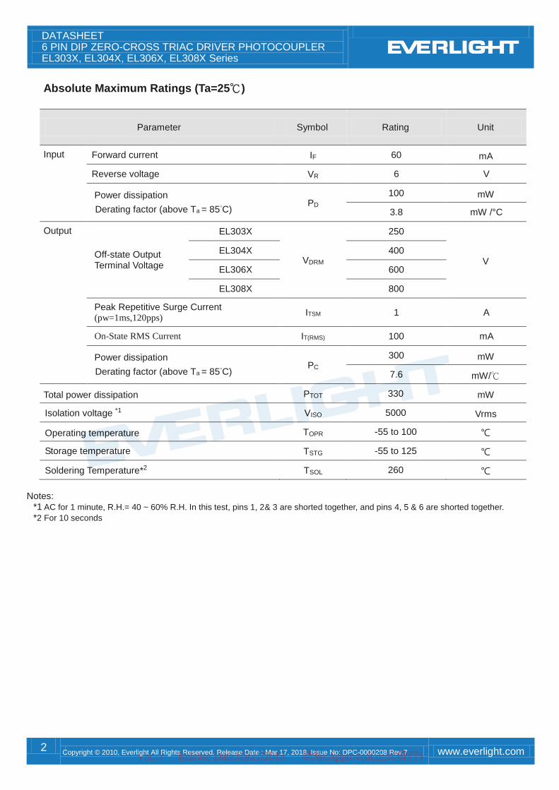
Absolute Maximum Ratings (Ta=25)
Parameter Symbol Rating Unit
Input Forward current IF 60 mA
Reverse voltage VR 6 V
Power dissipation
Derating factor (above Ta = 85°C) PD
100 mW
3.8 mW /°C
Output
Off-state Output Terminal Voltage
EL303X
VDRM
250
V EL304X 400
EL306X 600
EL308X 800
Peak Repetitive Surge Current (pw=1ms,120pps)
ITSM 1 A
On-State RMS Current IT(RMS) 100 mA
Power dissipation
Derating factor (above Ta = 85°C) PC
300 mW
7.6 mW/
Total power dissipation PTOT 330 mW
Isolation voltage *1 VISO 5000 Vrms
Operating temperature TOPR -55 to 100
Storage temperature TSTG -55 to 125
Soldering Temperature*2 TSOL 260
Notes:
*1 AC for 1 minute, R.H.= 40 ~ 60% R.H. In this test, pins 1, 2& 3 are shorted together, and pins 4, 5 & 6 are shorted together.
*2 For 10 seconds
Ver.:7 Release Date:03/21/2018 狀態:Approved(正式發行)
DATASHEET 6 PIN DIP ZERO-CROSS TRIAC DRIVER PHOTOCOUPLER EL303X, EL304X, EL306X, EL308X Series
3 Copyright © 2010, Everlight All Rights Reserved. Release Date : Mar 17, 2018. Issue No: DPC-0000208 Rev.7 www.everlight.com
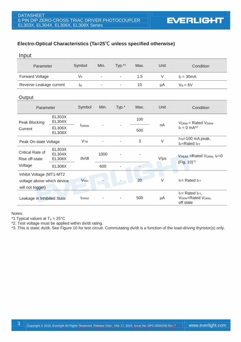
Electro-Optical Characteristics (Ta=25 unless specified otherwise)
Input
Parameter Symbol Min. Typ.*1 Max. Unit Condition
Forward Voltage VF - - 1.5 V IF = 30mA
Reverse Leakage current IR - - 10 µA VR = 6V
Output
Parameter Symbol Min. Typ.* Max. Unit Condition
Peak Blocking
Current
EL303X EL304X
IDRM1 - -
100
nA VDRM = Rated VDRM
IF = 0 mA*2 EL306X EL308X
500
Peak On-state Voltage VTM - - 3 V ITM=100 mA peak,
IF=Rated IFT
Critical Rate of
Rise off-state
Voltage
EL303X EL304X EL306X dv/dt
1000 - - V/µs
VPEAK =Rated VDRM, IF=0
(Fig. 10)*3 EL308X 600 - -
Inhibit Voltage (MT1-MT2
voltage above which device
will not trigger)
VINH - - 20 V IF= Rated IFT
Leakage in lnhibited State IDRM2 - - 500 µA IF= Rated IFT, VDRM=Rated VDRM, off state
Notes:
*1.Typical values at Ta = 25°C
*2. Test voltage must be applied within dv/dt rating. *3. This is static dv/dt. See Figure 10 for test circuit. Commutating dv/dt is a function of the load-driving thyristor(s) only.
Ver.:7 Release Date:03/21/2018 狀態:Approved(正式發行)
DATASHEET 6 PIN DIP ZERO-CROSS TRIAC DRIVER PHOTOCOUPLER EL303X, EL304X, EL306X, EL308X Series
4 Copyright © 2010, Everlight All Rights Reserved. Release Date : Mar 17, 2018. Issue No: DPC-0000208 Rev.7 www.everlight.com
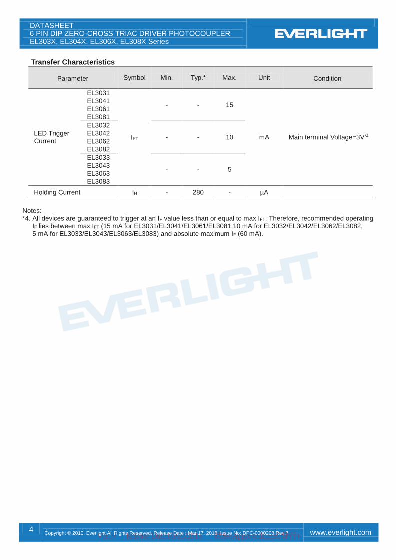
Transfer Characteristics
Parameter Symbol Min. Typ.* Max. Unit Condition
LED Trigger Current
EL3031
EL3041
EL3061
EL3081
IFT
- - 15
mA Main terminal Voltage=3V*4
EL3032
EL3042
EL3062
EL3082
- - 10
EL3033
EL3043
EL3063
EL3083
- - 5
Holding Current IH - 280 - µA
Notes: *4. All devices are guaranteed to trigger at an IF value less than or equal to max IFT. Therefore, recommended operating
IF lies between max IFT (15 mA for EL3031/EL3041/EL3061/EL3081,10 mA for EL3032/EL3042/EL3062/EL3082, 5 mA for EL3033/EL3043/EL3063/EL3083) and absolute maximum IF (60 mA).
Ver.:7 Release Date:03/21/2018 狀態:Approved(正式發行)

DATASHEET 6 PIN DIP ZERO-CROSS TRIAC DRIVER PHOTOCOUPLER EL303X, EL304X, EL306X, EL308X Series
5 Copyright © 2010, Everlight All Rights Reserved. Release Date : Mar 17, 2018. Issue No: DPC-0000208 Rev.7 www.everlight.com
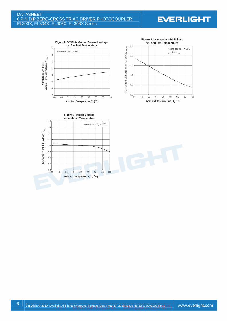
Typical Electro-Optical Characteristics Curves
Ver.:7 Release Date:03/21/2018 狀態:Approved(正式發行)
DATASHEET 6 PIN DIP ZERO-CROSS TRIAC DRIVER PHOTOCOUPLER EL303X, EL304X, EL306X, EL308X Series
6 Copyright © 2010, Everlight All Rights Reserved. Release Date : Mar 17, 2018. Issue No: DPC-0000208 Rev.7 www.everlight.com
Ver.:7 Release Date:03/21/2018 狀態:Approved(正式發行)

DATASHEET 6 PIN DIP ZERO-CROSS TRIAC DRIVER PHOTOCOUPLER EL303X, EL304X, EL306X, EL308X Series
7 Copyright © 2010, Everlight All Rights Reserved. Release Date : Mar 17, 2018. Issue No: DPC-0000208 Rev.7 www.everlight.com
Figure 10. Static dv/dt Test Circuit & Waveform
Measurement Method The high voltage pulse is set to the required VPEAK value and applied to the D.U.T. output side through the RC circuit above. LED current is not applied. The waveform VT is monitored using a x100 scope probe. By varying RTEST, the dv/dt (slope) is increased, until the D.U.T. is observed to trigger (waveform collapses). The dv/dt is then
decreased until the D.U.T. stops triggering. At this point, RC is recorded and the dv/dt calculated.
For example, VPEAK = 600V for EL306X series. The dv/dt value is calculated as follows:
VPEAK
0
Applied VT Waveform
RC
0.632 x VPEAK
0.632 x 600
RC
dv/dt = = 379.2
RC
0.632 x VPEAK
RC
dv/dt =
50 Ω
10 kΩ
D.U.T.
RTEST
High Voltage Pulse Source
CTEST VT
A
K
T1
T2
Zero Crossing Circuit
Ver.:7 Release Date:03/21/2018 狀態:Approved(正式發行)

DATASHEET 6 PIN DIP ZERO-CROSS TRIAC DRIVER PHOTOCOUPLER EL303X, EL304X, EL306X, EL308X Series
8 Copyright © 2010, Everlight All Rights Reserved. Release Date : Mar 17, 2018. Issue No: DPC-0000208 Rev.7 www.everlight.com
Order Information Part Number
EL303XY(Z)-V or EL304XY(Z)-V or EL306XY(Z)-V or EL308XY(Z)-V Note X = Part No. (1, 2 or 3) Y = Lead form option (S, S1, M or none) Z = Tape and reel option (TA, TB or none) V = VDE safety approved option
Option Description Packing quantity
None Standard DIP-6 65 units per tube
M Wide lead bend (0.4 inch spacing) 65 units per tube
S (TA) Surface mount lead form + TA tape & reel option 1000 units per reel
S (TB) Surface mount lead form + TB tape & reel option 1000 units per reel
S1 (TA) Surface mount lead form (low profile) + TA tape & reel option 1000 units per reel
S1 (TB) Surface mount lead form (low profile) + TB tape & reel option 1000 units per reel
Ver.:7 Release Date:03/21/2018 狀態:Approved(正式發行)
DATASHEET 6 PIN DIP ZERO-CROSS TRIAC DRIVER PHOTOCOUPLER EL303X, EL304X, EL306X, EL308X Series
9 Copyright © 2010, Everlight All Rights Reserved. Release Date : Mar 17, 2018. Issue No: DPC-0000208 Rev.7 www.everlight.com
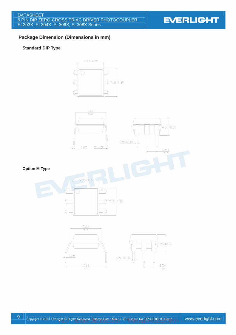
Package Dimension (Dimensions in mm)
Standard DIP Type
Option M Type
Ver.:7 Release Date:03/21/2018 狀態:Approved(正式發行)

DATASHEET 6 PIN DIP ZERO-CROSS TRIAC DRIVER PHOTOCOUPLER EL303X, EL304X, EL306X, EL308X Series
10 Copyright © 2010, Everlight All Rights Reserved. Release Date : Mar 17, 2018. Issue No: DPC-0000208 Rev.7 www.everlight.com
Option S Type
Option S1 Type
Ver.:7 Release Date:03/21/2018 狀態:Approved(正式發行)

DATASHEET 6 PIN DIP ZERO-CROSS TRIAC DRIVER PHOTOCOUPLER EL303X, EL304X, EL306X, EL308X Series
11 Copyright © 2010, Everlight All Rights Reserved. Release Date : Mar 17, 2018. Issue No: DPC-0000208 Rev.7 www.everlight.com
Recommended pad layout for surface mount leadform
Notes Suggested pad dimension is just for reference only. Please modify the pad dimension based on individual need.
Device Marking Notes EL denotes Everlight 3083 denotes Device Number Y denotes 1 digit Year code WW denotes 2 digit Week code V denotes VDE option
EL
3083
YWWV
Ver.:7 Release Date:03/21/2018 狀態:Approved(正式發行)
DATASHEET 6 PIN DIP ZERO-CROSS TRIAC DRIVER PHOTOCOUPLER EL303X, EL304X, EL306X, EL308X Series
12 Copyright © 2010, Everlight All Rights Reserved. Release Date : Mar 17, 2018. Issue No: DPC-0000208 Rev.7 www.everlight.com
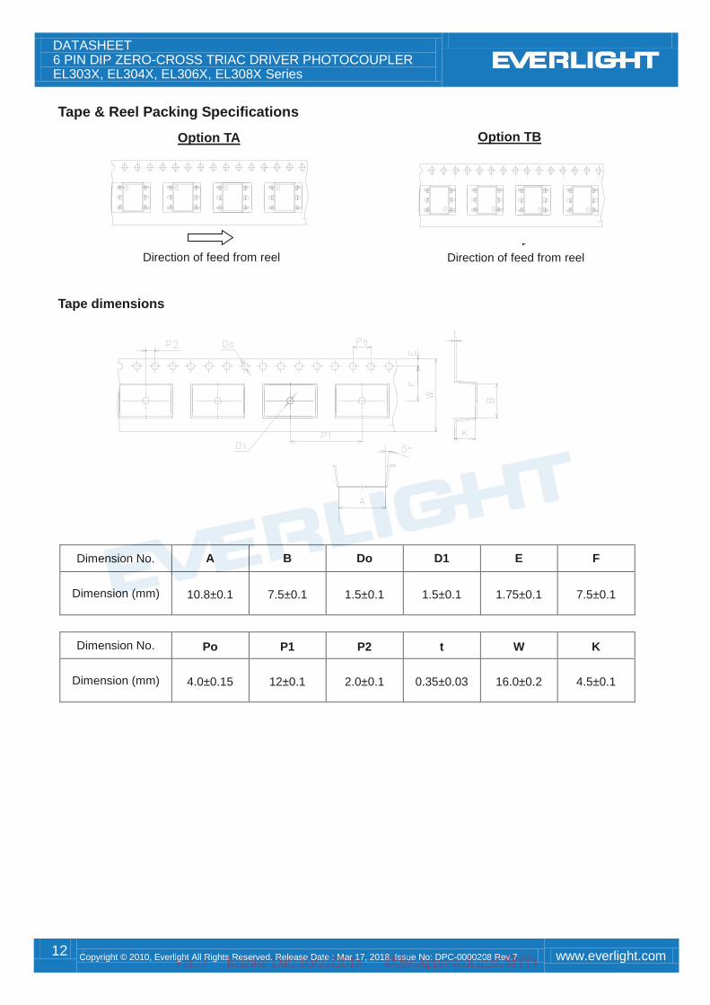
Tape & Reel Packing Specifications
Tape dimensions
Dimension No. A B Do D1 E F
Dimension (mm) 10.8±0.1 7.5±0.1 1.5±0.1 1.5±0.1 1.75±0.1 7.5±0.1
Dimension No. Po P1 P2 t W K
Dimension (mm) 4.0±0.15 12±0.1 2.0±0.1 0.35±0.03 16.0±0.2 4.5±0.1
Option TA Option TB
Direction of feed from reel Direction of feed from reel
Ver.:7 Release Date:03/21/2018 狀態:Approved(正式發行)
DATASHEET 6 PIN DIP ZERO-CROSS TRIAC DRIVER PHOTOCOUPLER EL303X, EL304X, EL306X, EL308X Series
13 Copyright © 2010, Everlight All Rights Reserved. Release Date : Mar 17, 2018. Issue No: DPC-0000208 Rev.7 www.everlight.com
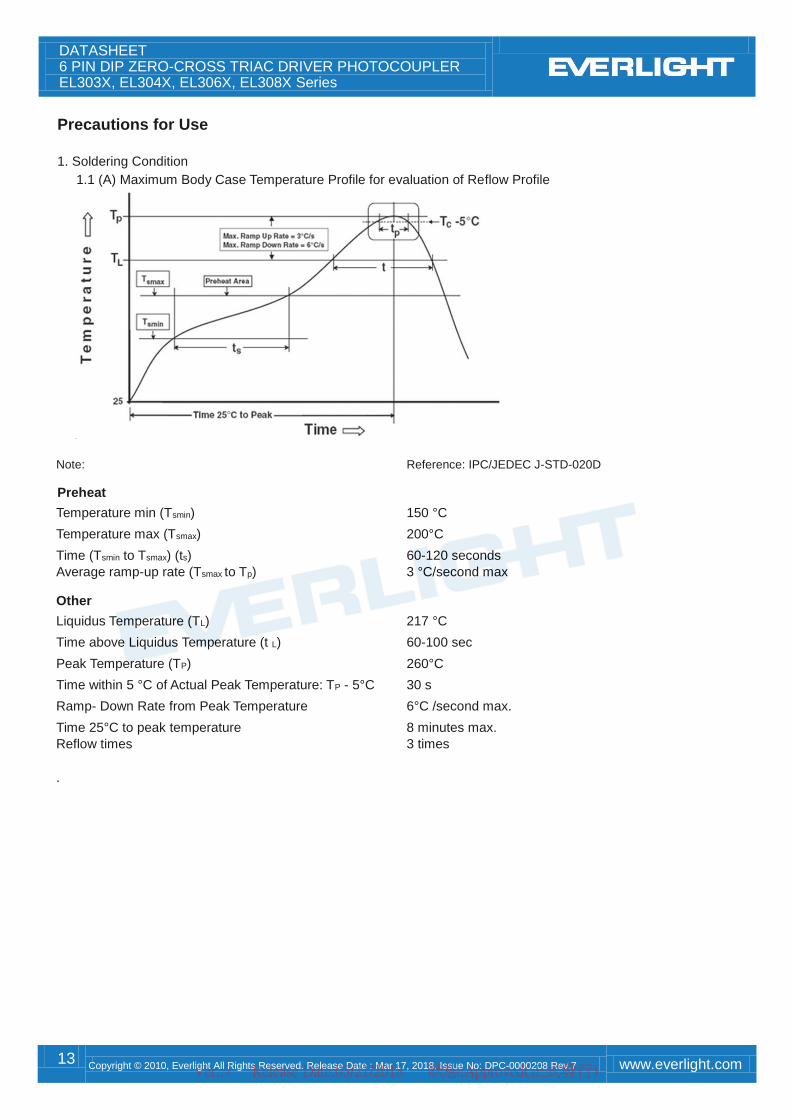
Precautions for Use 1. Soldering Condition
1.1 (A) Maximum Body Case Temperature Profile for evaluation of Reflow Profile
Note: Reference: IPC/JEDEC J-STD-020D
Preheat
Temperature min (Tsmin) 150 °C
Temperature max (Tsmax) 200°C
Time (Tsmin to Tsmax) (ts) 60-120 seconds
Average ramp-up rate (Tsmax to Tp) 3 °C/second max
Other
Liquidus Temperature (TL) 217 °C
Time above Liquidus Temperature (t L) 60-100 sec
Peak Temperature (TP) 260°C
Time within 5 °C of Actual Peak Temperature: TP - 5°C 30 s
Ramp- Down Rate from Peak Temperature 6°C /second max.
Time 25°C to peak temperature 8 minutes max.
Reflow times 3 times .
Ver.:7 Release Date:03/21/2018 狀態:Approved(正式發行)

DATASHEET 6 PIN DIP ZERO-CROSS TRIAC DRIVER PHOTOCOUPLER EL303X, EL304X, EL306X, EL308X Series
14 Copyright © 2010, Everlight All Rights Reserved. Release Date : Mar 17, 2018. Issue No: DPC-0000208 Rev.7 www.everlight.com
DISCLAIMER 1. Above specification may be changed without notice. EVERLIGHT will reserve authority on material change for above
specification.
2. The graphs shown in this datasheet are representing typical data only and do not show guaranteed values.
3. When using this product, please observe the absolute maximum ratings and the instructions for use outlined in these
specification sheets. EVERLIGHT assumes no responsibility for any damage resulting from use of the product which
does not comply with the absolute maximum ratings and the instructions included in these specification sheets.
4. These specification sheets include materials protected under copyright of EVERLIGHT. Reproduction in any form is
prohibited without the specific consent of EVERLIGHT.
5. This product is not intended to be used for military, aircraft, automotive, medical, life sustaining or life saving
applications or any other application which can result in human injury or death. Please contact authorized Everlight
sales agent for special application request.
6. Statements regarding the suitability of products for certain types of applications are based on Everlight’s knowledge
of typical requirements that are often placed on Everlight products in generic applications. Such statements are not
binding statements about the suitability of products for a particular application. It is the customer’s responsibility to
validate that a particular product with the properties described in the product specification is suitable for use in a
particular application. Parameters provided in datasheets and/or specifications may vary in different applications and
performance may vary over time. All operating parameters, including typical parameters, must be validated for each
customer application by the customer’s technical experts. Product specifications do not expand or otherwise modify
Everlight’s terms and conditions of purchase, including but not limited to the warranty expressed therein.
Ver.:7 Release Date:03/21/2018 狀態:Approved(正式發行)
Related Documents