6 IN. BALL LAUNCHER Pumper’s Trailer Mounted OPERATOR’S PARTS and MAINTENANCE MANUAL 2014 EDITION BL-MAN-6PT

Welcome message from author
This document is posted to help you gain knowledge. Please leave a comment to let me know what you think about it! Share it to your friends and learn new things together.
Transcript
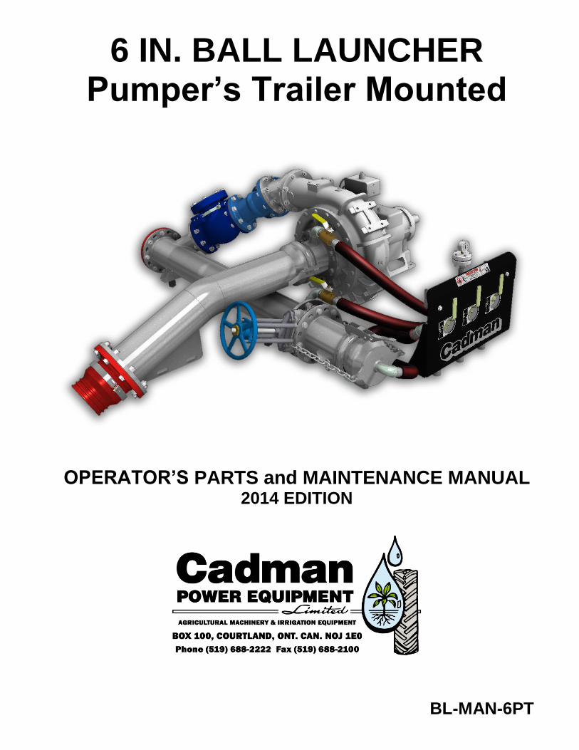
6 IN. BALL LAUNCHER Pumper’s Trailer Mounted
OPERATOR’S PARTS and MAINTENANCE MANUAL 2014 EDITION
BL-MAN-6PT

T
itle
BL-MAN-6PT
Cre
atio
n
10-March-2006 by
Ivon LeBlanc
Revis
ion
10-August-2014 by
Ivon LeBlanc Clean-out Ball Launcher - 6 IN.
Page 1 of 18 Cadman Power Equipment ▪ BOX 100, Courtland, Ontario, Canada N0J-1E0 ▪ Phone: 519-688-2222 ▪ Fax: 519-688-2100 ▪ www.cadmanpower.com
Table of Contents
Table of Contents ...................................................................................................... 1
Clean-out Ball Launcher System ............................................................................... 3
Safety Note ................................................................................................................ 3
Exercise Extreme Caution When Working With Compressed Air! ............................. 4
Important Note ........................................................................................................... 5
Safety Decals ............................................................................................................. 6
Clean-out Ball Launcher Operation ............................................................................ 7
Clean-out Suction Line............................................................................................... 13
Required Maintenance ............................................................................................... 16
Useful Information ...................................................................................................... 18
BL-MAN-6PT Clean-out Ball Launcher - 6 IN.
Page 2 of 18 Cadman Power Equipment ▪ BOX 100, Courtland, Ontario, Canada N0J-1E0 ▪ Phone: 519-688-2222 ▪ Fax: 519-688-2100 ▪ www.cadmanpower.com
BL-MAN-6PT Clean-out Ball Launcher - 6 IN.
Page 3 of 18 Cadman Power Equipment ▪ BOX 100, Courtland, Ontario, Canada N0J-1E0 ▪ Phone: 519-688-2222 ▪ Fax: 519-688-2100 ▪ www.cadmanpower.com
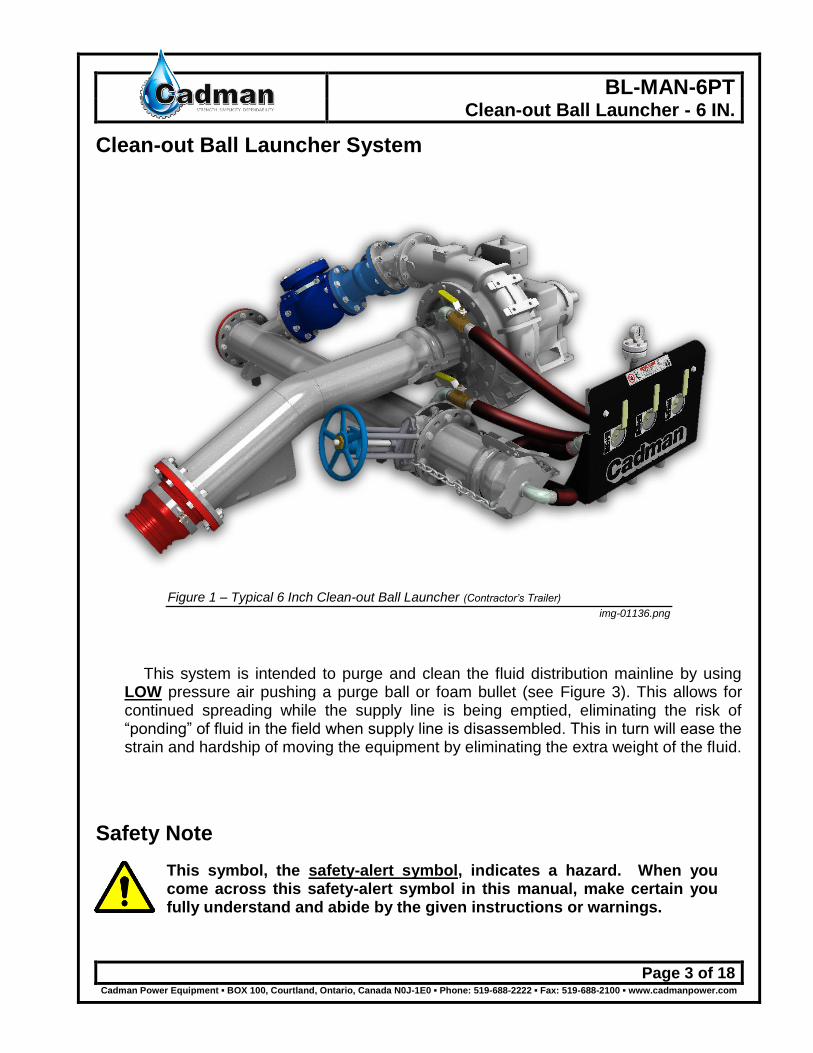
Clean-out Ball Launcher System
Figure 1 – Typical 6 Inch Clean-out Ball Launcher (Contractor’s Trailer) img-01136.png
This system is intended to purge and clean the fluid distribution mainline by using LOW pressure air pushing a purge ball or foam bullet (see Figure 3). This allows for continued spreading while the supply line is being emptied, eliminating the risk of “ponding” of fluid in the field when supply line is disassembled. This in turn will ease the strain and hardship of moving the equipment by eliminating the extra weight of the fluid.
Safety Note
This symbol, the safety-alert symbol, indicates a hazard. When you come across this safety-alert symbol in this manual, make certain you fully understand and abide by the given instructions or warnings.
BL-MAN-6PT Clean-out Ball Launcher - 6 IN.
Page 4 of 18 Cadman Power Equipment ▪ BOX 100, Courtland, Ontario, Canada N0J-1E0 ▪ Phone: 519-688-2222 ▪ Fax: 519-688-2100 ▪ www.cadmanpower.com
Exercise Extreme Caution When Working With Compressed Air!
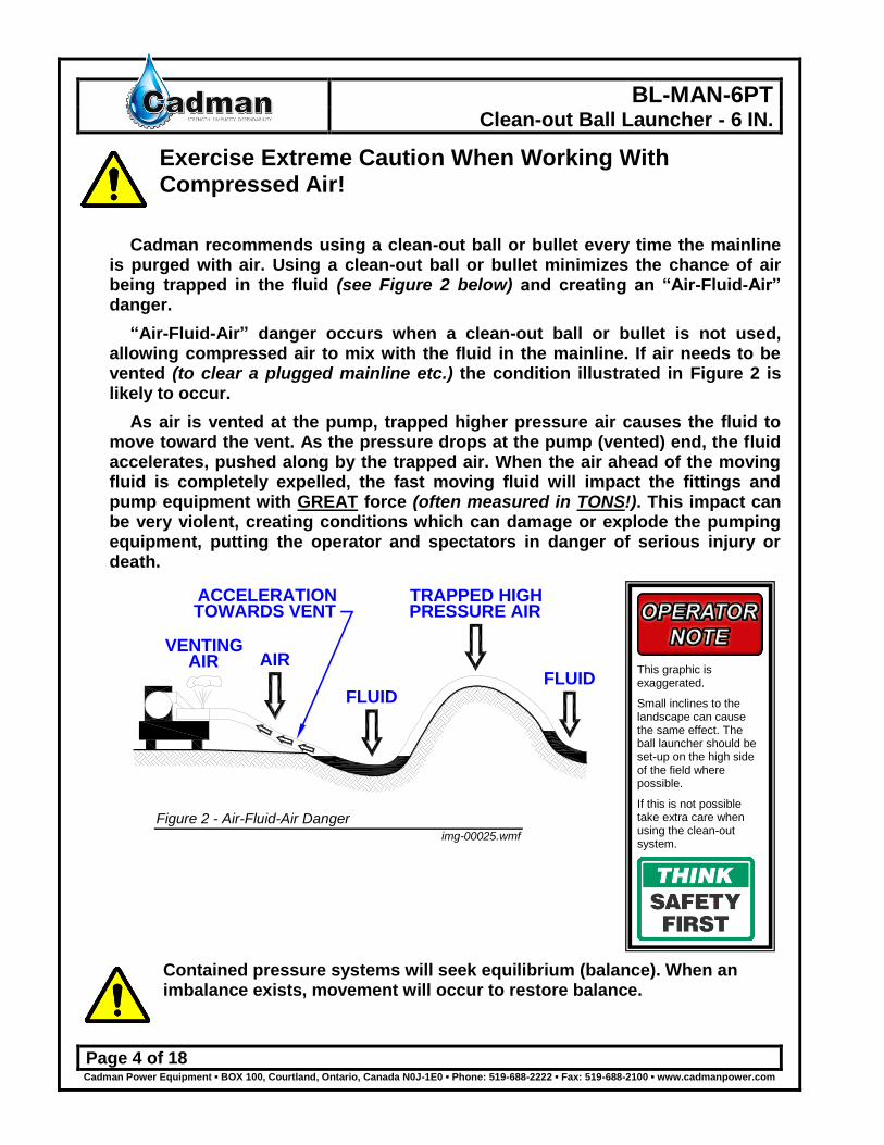
Cadman recommends using a clean-out ball or bullet every time the mainline is purged with air. Using a clean-out ball or bullet minimizes the chance of air being trapped in the fluid (see Figure 2 below) and creating an “Air-Fluid-Air” danger.
“Air-Fluid-Air” danger occurs when a clean-out ball or bullet is not used, allowing compressed air to mix with the fluid in the mainline. If air needs to be vented (to clear a plugged mainline etc.) the condition illustrated in Figure 2 is likely to occur.
As air is vented at the pump, trapped higher pressure air causes the fluid to move toward the vent. As the pressure drops at the pump (vented) end, the fluid accelerates, pushed along by the trapped air. When the air ahead of the moving fluid is completely expelled, the fast moving fluid will impact the fittings and pump equipment with GREAT force (often measured in TONS!). This impact can be very violent, creating conditions which can damage or explode the pumping equipment, putting the operator and spectators in danger of serious injury or death.
VENTINGAIR AIR
FLUID
TRAPPED HIGHPRESSURE AIR
FLUID
ACCELERATIONTOWARDS VENT
Figure 2 - Air-Fluid-Air Danger img-00025.wmf
Contained pressure systems will seek equilibrium (balance). When an imbalance exists, movement will occur to restore balance.
This graphic is exaggerated.
Small inclines to the landscape can cause the same effect. The ball launcher should be set-up on the high side of the field where possible.
If this is not possible take extra care when using the clean-out system.

BL-MAN-6PT Clean-out Ball Launcher - 6 IN.
Page 5 of 18 Cadman Power Equipment ▪ BOX 100, Courtland, Ontario, Canada N0J-1E0 ▪ Phone: 519-688-2222 ▪ Fax: 519-688-2100 ▪ www.cadmanpower.com
Definitions
Clean-out Ball: A device used to purge or clean the mainline of a fluid distribution system. This device can take the form of a ball or bullet. See Figure 3.
Figure 3 - Clean-out Ball and Bullet img-00016.gif
Important Note
Things to keep in mind while using the Clean-out Ball Launcher System are:
The hose is a high volume “Receiver Tank” containing a large amount of fluid. Be sure to allow enough spreading area to properly distribute the hose contents.
Ø 6” hose contains approximately 1 ½ US Gallons per foot Ø 8” hose contains approximately 2 ⅔ US Gallons per foot
660 1320 1980 2640 3300 3960 4620 5280 5940 6600 Feet
Ø 6" 969 1939 2908 3877 4847 5816 6785 7755 8724 9693 US Gal
Ø 8" 1723 3447 5170 6893 8616 10340 12063 13786 15509 17233 US Gal
Hose couplings must be maintained and in good working order. Check for broken or damaged couplings and replace where necessary.
Air pressure should be kept to the lowest level required to complete the clean-out process. Excess pressure will result in equipment damage and may result in personal injury or death.
BL-MAN-6PT Clean-out Ball Launcher - 6 IN.
Page 6 of 18 Cadman Power Equipment ▪ BOX 100, Courtland, Ontario, Canada N0J-1E0 ▪ Phone: 519-688-2222 ▪ Fax: 519-688-2100 ▪ www.cadmanpower.com
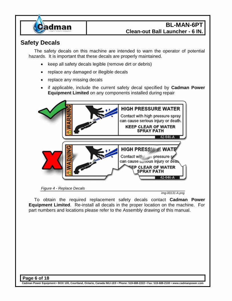
Safety Decals
The safety decals on this machine are intended to warn the operator of potential hazards. It is important that these decals are properly maintained.
keep all safety decals legible (remove dirt or debris)
replace any damaged or illegible decals
replace any missing decals
if applicable, include the current safety decal specified by Cadman Power Equipment Limited on any components installed during repair
Figure 4 - Replace Decals img-00131-A.png
To obtain the required replacement safety decals contact Cadman Power Equipment Limited. Re-install all decals in the proper location on the machine. For part numbers and locations please refer to the Assembly drawing of this manual.
BL-MAN-6PT Clean-out Ball Launcher - 6 IN.
Page 7 of 18 Cadman Power Equipment ▪ BOX 100, Courtland, Ontario, Canada N0J-1E0 ▪ Phone: 519-688-2222 ▪ Fax: 519-688-2100 ▪ www.cadmanpower.com
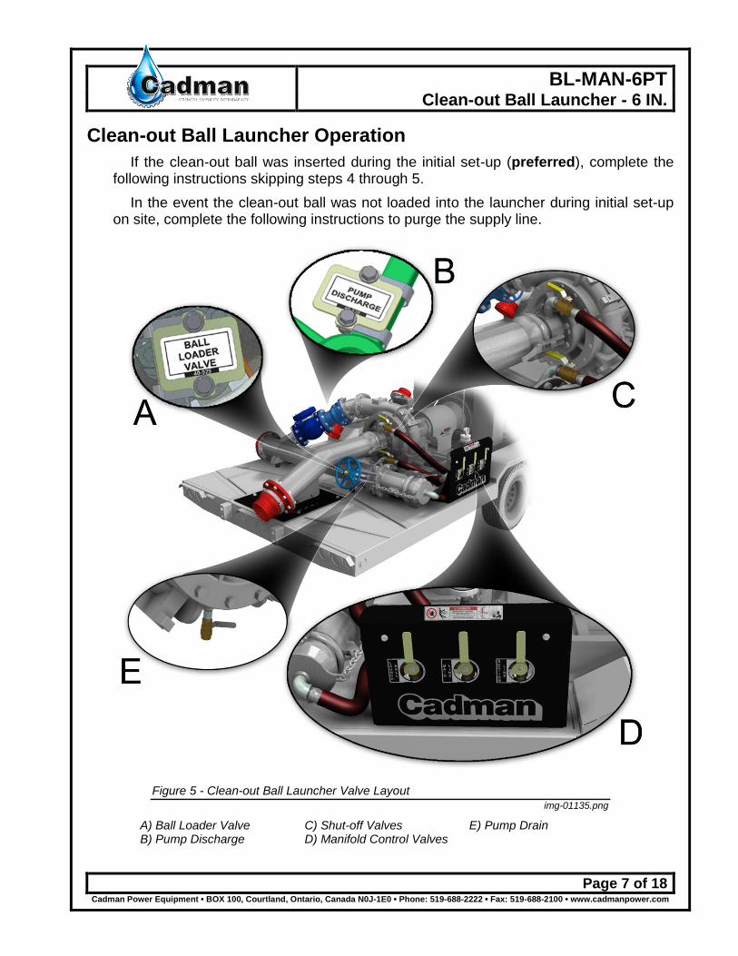
Clean-out Ball Launcher Operation
If the clean-out ball was inserted during the initial set-up (preferred), complete the following instructions skipping steps 4 through 5.
In the event the clean-out ball was not loaded into the launcher during initial set-up on site, complete the following instructions to purge the supply line.
Figure 5 - Clean-out Ball Launcher Valve Layout img-01135.png
A) Ball Loader Valve B) Pump Discharge
C) Shut-off Valves D) Manifold Control Valves
E) Pump Drain
BL-MAN-6PT Clean-out Ball Launcher - 6 IN.
Page 8 of 18 Cadman Power Equipment ▪ BOX 100, Courtland, Ontario, Canada N0J-1E0 ▪ Phone: 519-688-2222 ▪ Fax: 519-688-2100 ▪ www.cadmanpower.com
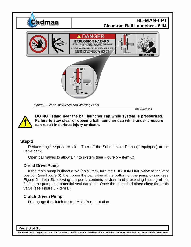
Figure 6 – Valve Instruction and Warning Label img-01137.png
DO NOT stand near the ball launcher cap while system is pressurized. Failure to stay clear or opening ball launcher cap while under pressure can result in serious injury or death.
Step 1
Reduce engine speed to idle. Turn off the Submersible Pump (if equipped) at the valve bank.
Open ball valves to allow air into system (see Figure 5 – item C).
Direct Drive Pump
If the main pump is direct drive (no clutch), turn the SUCTION LINE valve to the vent position (see Figure 6), then open the ball valve at the bottom on the pump casing (see Figure 5 - item E), allowing the pump contents to drain and preventing heating of the fluid in the pump and potential seal damage. Once the pump is drained close the drain valve (see Figure 5 - item E).
Clutch Driven Pump
Disengage the clutch to stop Main Pump rotation.
BL-MAN-6PT Clean-out Ball Launcher - 6 IN.
Page 9 of 18 Cadman Power Equipment ▪ BOX 100, Courtland, Ontario, Canada N0J-1E0 ▪ Phone: 519-688-2222 ▪ Fax: 519-688-2100 ▪ www.cadmanpower.com
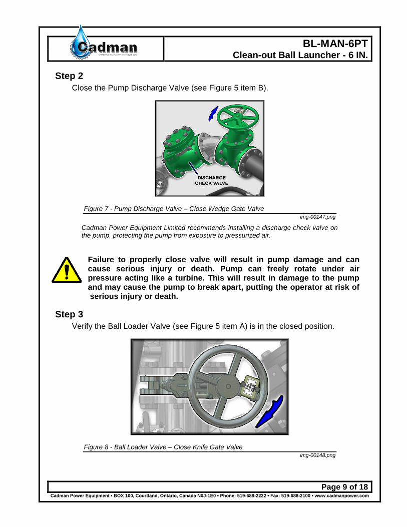
Step 2
Close the Pump Discharge Valve (see Figure 5 item B).
Figure 7 - Pump Discharge Valve – Close Wedge Gate Valve img-00147.png
Cadman Power Equipment Limited recommends installing a discharge check valve on the pump, protecting the pump from exposure to pressurized air.
Failure to properly close valve will result in pump damage and can cause serious injury or death. Pump can freely rotate under air pressure acting like a turbine. This will result in damage to the pump and may cause the pump to break apart, putting the operator at risk of serious injury or death.
Step 3
Verify the Ball Loader Valve (see Figure 5 item A) is in the closed position.
Figure 8 - Ball Loader Valve – Close Knife Gate Valve
img-00148.png

BL-MAN-6PT Clean-out Ball Launcher - 6 IN.
Page 10 of 18 Cadman Power Equipment ▪ BOX 100, Courtland, Ontario, Canada N0J-1E0 ▪ Phone: 519-688-2222 ▪ Fax: 519-688-2100 ▪ www.cadmanpower.com
Step 4
Turn ball valve labeled “LAUNCH BALL” to the VENT (see Figure 6) BEFORE attempting to load clean-out ball.
Figure 9 – Launch Ball Valve – Turn to VENT Position img-01138.png
Step 5
Remove Clean-out Ball Loader cap, insert the clean-out ball and recap the loader. Open Ball Loader Valve completely (see Figure 5 item A).
Figure 10 - Ball Loader Valve – Open Knife Gate Valve img-00151.png

BL-MAN-6PT Clean-out Ball Launcher - 6 IN.
Page 11 of 18 Cadman Power Equipment ▪ BOX 100, Courtland, Ontario, Canada N0J-1E0 ▪ Phone: 519-688-2222 ▪ Fax: 519-688-2100 ▪ www.cadmanpower.com
Step 6
Turn ball valve labeled “Launch Ball” to purge position (see Figure 6).
Figure 11 - Launch Ball Valve – Turn to PURGE Position img-01139.png
Step 7
Turn on compressor. Set engine to operate at 1200 – 1500 rpm.
Step 8
Verify that ball has entered the mainline. Tap the hose and it should have a hollow sound. Do the following in the sequence stated; Turn ball valve labeled “MAIN LINE” to PURGE (see Figure 5 item D and Figure 6) to divert air to mainline tube, turn ball valve labeled “LAUNCH BALL” to the OFF position (see Figure 5 item D and Figure 6). Completely close the Ball Loader Valve IMMEDIATELY! (see Figure 5 item A)
Failure to properly close Ball Loader Valve may cause equipment damage with the potential for serious injury or death. In the event of flow reversal, the Ball Loader Valve helps protect the operator from a burst hazard.
Step 9
Continue adding air until the Clean-out Ball is past the halfway point in the mainline. Cycle the compressor on and off to add air intermittently until the ball exits the hose. This ensures minimal air pressure remains when the line clears.
Step 10
Turn off compressor. Reduce engine speed to idle.
BL-MAN-6PT Clean-out Ball Launcher - 6 IN.
Page 12 of 18 Cadman Power Equipment ▪ BOX 100, Courtland, Ontario, Canada N0J-1E0 ▪ Phone: 519-688-2222 ▪ Fax: 519-688-2100 ▪ www.cadmanpower.com
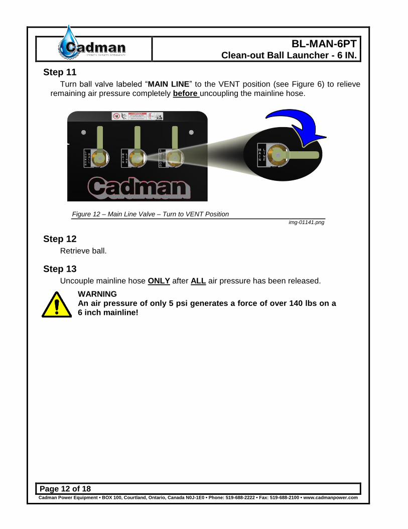
Step 11
Turn ball valve labeled “MAIN LINE” to the VENT position (see Figure 6) to relieve remaining air pressure completely before uncoupling the mainline hose.
Figure 12 – Main Line Valve – Turn to VENT Position img-01141.png
Step 12
Retrieve ball.
Step 13
Uncouple mainline hose ONLY after ALL air pressure has been released.
WARNING An air pressure of only 5 psi generates a force of over 140 lbs on a 6 inch mainline!
BL-MAN-6PT Clean-out Ball Launcher - 6 IN.
Page 13 of 18 Cadman Power Equipment ▪ BOX 100, Courtland, Ontario, Canada N0J-1E0 ▪ Phone: 519-688-2222 ▪ Fax: 519-688-2100 ▪ www.cadmanpower.com
Clean-out Suction Line
To clean-out the suction line of the pumping unit complete the following steps.
Step 1
Reduce engine speed to idle. Turn off the Submersible Pump (if equipped) at the valve bank.
Direct Drive Pump (no clutch)
IMPORTANT: Prior to extended clean-out operations, you must drain the pump of fluid. Open the ball valve at the bottom of the pump casing (see Figure 5 item E), allowing the contents to drain. Once all fluid has been drained close the ball valve. This will prevent the heating of the fluid in the pump and potential seal damage.
Clutch Driven Pump
Disengage the clutch to stop Main Pump rotation.
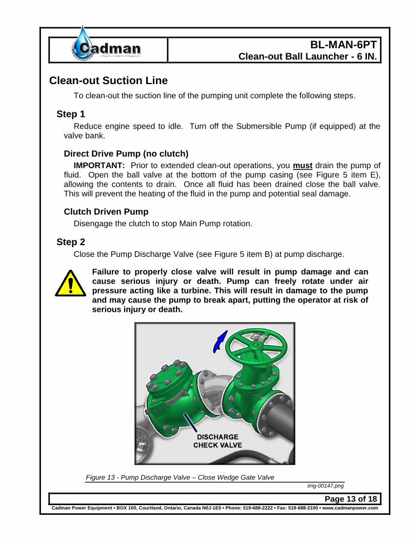
Step 2
Close the Pump Discharge Valve (see Figure 5 item B) at pump discharge.
Failure to properly close valve will result in pump damage and can cause serious injury or death. Pump can freely rotate under air pressure acting like a turbine. This will result in damage to the pump and may cause the pump to break apart, putting the operator at risk of serious injury or death.
Figure 13 - Pump Discharge Valve – Close Wedge Gate Valve img-00147.png

BL-MAN-6PT Clean-out Ball Launcher - 6 IN.
Page 14 of 18 Cadman Power Equipment ▪ BOX 100, Courtland, Ontario, Canada N0J-1E0 ▪ Phone: 519-688-2222 ▪ Fax: 519-688-2100 ▪ www.cadmanpower.com
Step 3
Turn ball valve labeled “SUCTION LINE” to the PURGE (see Figure 5 item D) to divert air to suction line.
Figure 14 - Suction Line – Turn to PURGE Position img-01142.png
Step 4
Turn on compressor. Set engine to operate at 1200 – 1500 rpm.
Step 5
Allow time for liquid to be purged from suction line.
Step 6
Turn off compressor. Reduce engine speed to idle.

BL-MAN-6PT Clean-out Ball Launcher - 6 IN.
Page 15 of 18 Cadman Power Equipment ▪ BOX 100, Courtland, Ontario, Canada N0J-1E0 ▪ Phone: 519-688-2222 ▪ Fax: 519-688-2100 ▪ www.cadmanpower.com
Step 7
Turn ball valve labeled “SUCTION LINE” to vent position (see Figure 6) to allow all air pressure to be released before uncoupling the suction hose.
Figure 15 – Suction Line – Turn to VENT Position img-01143.png
Step 8
Uncouple suction line hose ONLY after ALL air pressure has been released.
WARNING An air pressure of only 5 psi generates a force of over 140 lbs on a 6 inch mainline!
BL-MAN-6PT Clean-out Ball Launcher - 6 IN.
Page 16 of 18 Cadman Power Equipment ▪ BOX 100, Courtland, Ontario, Canada N0J-1E0 ▪ Phone: 519-688-2222 ▪ Fax: 519-688-2100 ▪ www.cadmanpower.com
Required Maintenance
Prevention of mechanical failure is the goal of any good maintenance schedule. The secret to preventing unwanted down time is to adhere to a maintenance schedule suited to the way you use the equipment. Your maintenance schedule should include the following minimum requirements:
Maintenance must be done ONLY when the machine is shut down and is in a non-loaded condition. This means that no fluid is being pumped through the system. All system pressure must be discharged prior to any maintenance operation is performed.
Each Use
Maintenance Item Figure Procedure Visually inspect equipment N / A Walk around the unit and inspect for loose, missing
or damaged items. Check the condition of the ball loader plug, hoses and valves. Replace missing or damaged items and tighten loosened items.
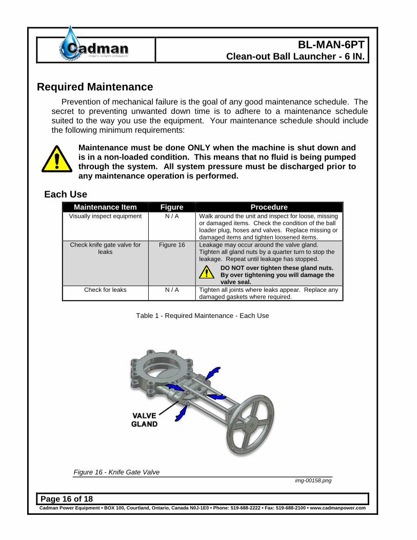
Check knife gate valve for leaks
Figure 16 Leakage may occur around the valve gland. Tighten all gland nuts by a quarter turn to stop the leakage. Repeat until leakage has stopped.
DO NOT over tighten these gland nuts. By over tightening you will damage the valve seal.
Check for leaks N / A Tighten all joints where leaks appear. Replace any damaged gaskets where required.
Table 1 - Required Maintenance - Each Use
Figure 16 - Knife Gate Valve img-00158.png
BL-MAN-6PT Clean-out Ball Launcher - 6 IN.
Page 17 of 18 Cadman Power Equipment ▪ BOX 100, Courtland, Ontario, Canada N0J-1E0 ▪ Phone: 519-688-2222 ▪ Fax: 519-688-2100 ▪ www.cadmanpower.com
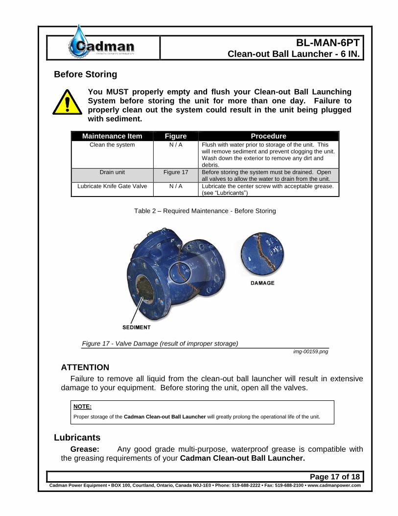
Before Storing
You MUST properly empty and flush your Clean-out Ball Launching System before storing the unit for more than one day. Failure to properly clean out the system could result in the unit being plugged with sediment.
Maintenance Item Figure Procedure Clean the system N / A Flush with water prior to storage of the unit. This
will remove sediment and prevent clogging the unit. Wash down the exterior to remove any dirt and debris.
Drain unit Figure 17 Before storing the system must be drained. Open all valves to allow the water to drain from the unit.
Lubricate Knife Gate Valve N / A Lubricate the center screw with acceptable grease. (see “Lubricants”)
Table 2 – Required Maintenance - Before Storing
Figure 17 - Valve Damage (result of improper storage) img-00159.png
ATTENTION
Failure to remove all liquid from the clean-out ball launcher will result in extensive damage to your equipment. Before storing the unit, open all the valves.
Lubricants
Grease: Any good grade multi-purpose, waterproof grease is compatible with the greasing requirements of your Cadman Clean-out Ball Launcher.
NOTE:
Proper storage of the Cadman Clean-out Ball Launcher will greatly prolong the operational life of the unit.

BL-MAN-6PT Clean-out Ball Launcher - 6 IN.
Page 18 of 18 Cadman Power Equipment ▪ BOX 100, Courtland, Ontario, Canada N0J-1E0 ▪ Phone: 519-688-2222 ▪ Fax: 519-688-2100 ▪ www.cadmanpower.com
Useful Information
LENGTH
1 FOOT = 12 Inches 1 METER = 39.37 Inches
1 ROD = 0.3048 Meter 1 MILE = 3.2808 Feet
AREA
1 SQUARE FOOT = 144 Square Inches = 0.0929 Square Meters
1 SQUARE YARD = 1296 Square Inches = 0.8361 Square Meters
1 SQUARE METER = 1549.4 Square Inches = 10.764 Square Feet
1 ACRE = 43560 Square Feet = 4047 Square Meters = 0.4047 Hectare
1 HECTARE = 107642.62 Square Feet = 10000 Square Meters = 2.47105 Acres
1 SQUARE MILE = 640 Acres = 259 Hectares
VOLUME
1 GALLON ( US ) = 0.8327 Imperial Gallons = 231 Cubic Inches = 0.1337 Cubic Feet = 8.345 Pounds
1 CUBIC FOOT = 1728 Cubic Inches = 7.48 Gallons ( US ) = 62.4 Pounds = 28.32 Liters
1 ACRE INCH = 27154 Gallons ( US ) = 254 Cubic Meters / Hectare
AREA OF A CIRCLE = Diameter x Diameter x 0.7854
CYLINDER VOLUME (US GAL.) = Diameter (ft.) x Diameter (ft.) x Length (ft.) x 5.8748
Related Documents