DeltaV Process Control System CM4120 Unit Operations Lab January 2011 1

6 2011 DeltaV Process Control System
Jan 03, 2016
dELTAv
Welcome message from author
This document is posted to help you gain knowledge. Please leave a comment to let me know what you think about it! Share it to your friends and learn new things together.
Transcript

DeltaV Process Control System
CM4120Unit Operations Lab
January 2011
1
OutlineEvolution of Process Control
Layout and Architecture of the DeltaV system in the PSCC
Physical connections between process instrumentation and the DCS
What the engineers and operators see
2
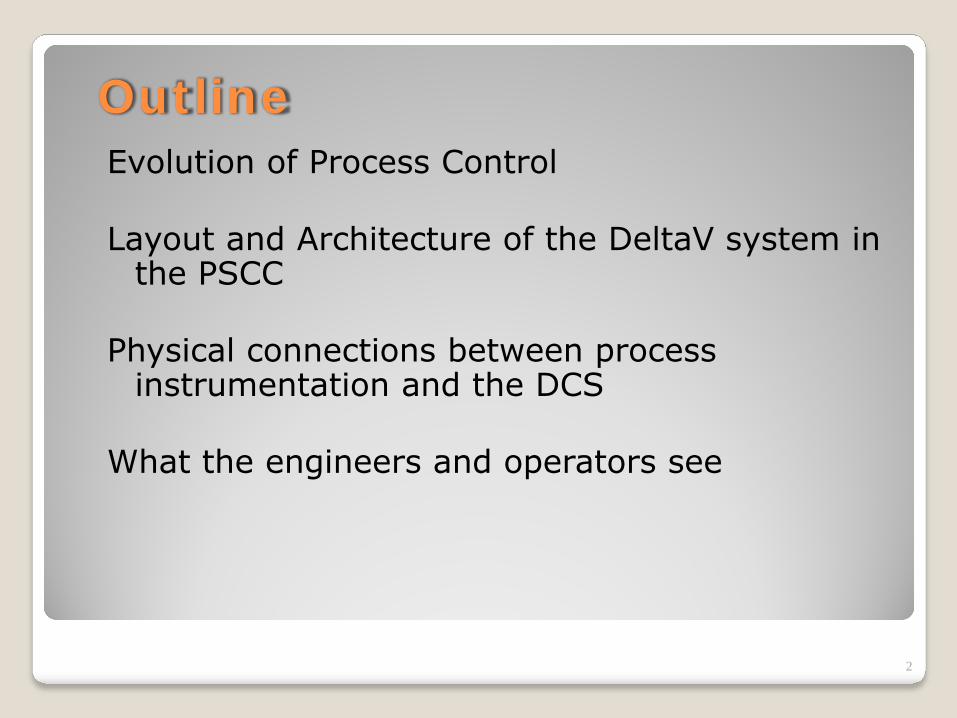
Evolution of Controllers1930’s – Pneumatic Controllers• air pressure w/ flappers, bellows, and valves
adjust valve position based on measured process variable for P, PI, later PID control
1950’s – Electronic Controllers• transistors, resistors, and capacitors for P, PI,
PID control• capable of remote installation1960’s – Mainframe Computer Control• Refineries were typical users• Alarming capability and supervisory control• Single point of failure, no user-friendly
graphical interface
3

Evolution of ControllersLate 1970’s – Distributed Control Systems
(DCS)• Networked computers distributed thru plant• Pre-configured controllers• Data archival capabilities• Included an operator console• Hardware was proprietaryLate 1990’s – DSC’s built on commodity
hardware platforms (COTS)• Better scalability• Affordable
4

Distributed Control System (DCS) Functionality
Continuous control of processing equipmentPre-programmed control software – needs only to be configuredControl functions are distributed throughout redundant, deterministic networked computer architecture◦ I/O interface and level 1 (basic) control functions◦ advanced control functions◦ interactive graphical interface (HMI)
5
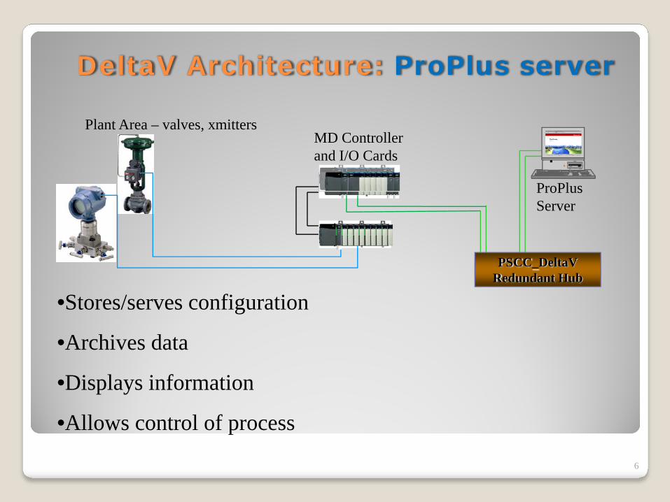
DeltaV Architecture: ProPlus server
6
•Stores/serves configuration
•Archives data
•Displays information
•Allows control of process
PSCC_DeltaVRedundant Hub
ProPlusServer
MD Controllerand I/O Cards
Plant Area – valves, xmitters

DeltaV Architecture: Operator Stations
7
•Archive data
•Display information (HMI)
•Allows process changes
PSCC_DeltaVRedundant Hub
ProPlusServer
MD Controllerand I/O Cards
Plant Area – valves, xmitters
Operator Stations
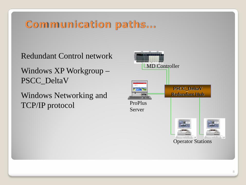
Communication paths…
8
Redundant Control network
Windows XP Workgroup –PSCC_DeltaV
Windows Networking and TCP/IP protocol
Operator Stations
PSCC_DeltaVRedundant Hub
ProPlusServer
MD Controller

DeltaV’s MD Controller and I/O –How it connects to the process…
9
MD Controllerand I/O Cards
Plant Area – valves, xmitters
I/O cards are specific to device requirements•4-20 mA input, 4-20 mA output
•24 VDC input, 24 VDC output, etc.
•Foundation Fieldbus Interface

Emerson’s DeltaV System –Current State of the Technology
10
PID control
Discrete logic control
Signal conversions
Alarming
Fuzzy control, etc.
are continuously executed by the “MD” controller

Wiring Systems Connect Transmittersto DCS – at the Instrument End:
11
Wiring to field junction cabinet
RTD or T/C head
Temperature transmitters
Wiring from transmitter to temp measuring element
Level transmitter

Wiring Systems Connect Transmittersto DCS – at a Marshalling Cabinet:
12
Single pairs from field devices
8 pr. Cables to controller cabinet
8-pr. cables run from Field Junction Box (Marshalling Cabinet) to Distributed Control System
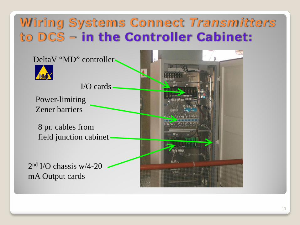
Wiring Systems Connect Transmittersto DCS – in the Controller Cabinet:
13
DeltaV “MD” controller
8 pr. cables from field junction cabinet
Power-limiting Zener barriers
I/O cards
2nd I/O chassis w/4-20 mA Output cards

Wiring Systems Connect DCS to Transducers – at Marshalling Cabinet:
14
Wire prs. to transducers
Current to pneumatic transducers
Air lines to control valves
8-pr. cable from controller cabinet

Regulatory Control Valve
15
Air line from I/P transducer
Actuator w/ positioner
Control valve
Block valves
Bypass valve

Output Signals from Control Systemto Control Solenoids
16
8-pr. cable from controller cabinet
Solenoids for 2-position air-actuated ball valves
Air lines to ball valves
Wire prs. to solenoids
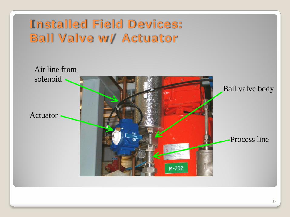
Installed Field Devices: Ball Valve w/ Actuator
17
Air line from solenoid
Actuator
Ball valve body
Process line

DeltaV & Foundation Fieldbus
18
(4) mass flows, (4) densities,
and (4) RTD temps
(3) 8-multiplexed RTD temps
(2) temp-only transmitters
(1) wire

The directory tree for our DeltaVsystem…
19
Control modules
ProPlus server
MD controller w/ I/O cards and controllers
Fieldbus I/O card w/instruments
Operator Stations
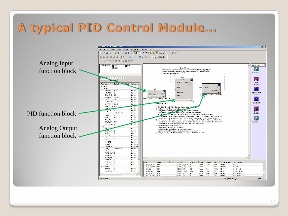
A typical PID Control Module…
20
Analog Input function block
PID function block
Analog Output function block
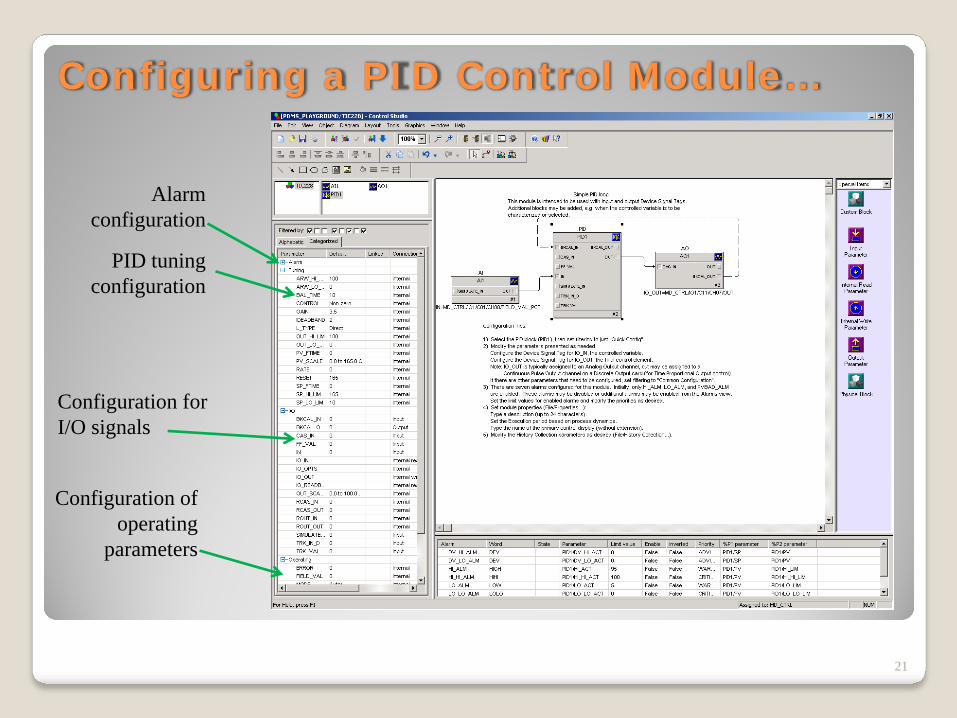
Configuring a PID Control Module…
21
PID tuning configuration
Configuration for I/O signals
Configuration of operating
parameters
Alarm configuration

What an operator might see…
22

Referenceswww.emersonprocess.com/rosemount/,
Rosemount, Inc., Oct. 2006.www.emersonprocess.com/micromotion/, Micro
Motion, Inc., Oct. 2006.
23
Related Documents