5S–FE ENGINE – 5S–FE ENGINE EG1–1

Welcome message from author
This document is posted to help you gain knowledge. Please leave a comment to let me know what you think about it! Share it to your friends and learn new things together.
Transcript

5S–FE ENGINE
–5S–FE ENGINEEG1–1

DESCRIPTIONThe 5S–FE engine is an in–line, 4–cylinder, 2.2 liter DOHC 16–valve engine.
ENGINE MECHANICAL
–5S–FE ENGINE ENGINE MECHANICALEG1–2

The 5S–FE engine is an in–line, 4–cylinder engine with the cylinders numbered 1–2–3–4from the front. The crankshaft is supported by five bearings inside the crankcase. These bearingsare made of aluminum alloy.The crankshaft is integrated with eight weights for balance. Oil holes are placed in the center ofthe crankshaft to supply oil to the connecting rods, bearing, pistons and other components.The firing order is 1–3–4–2. The cylinder head is made of aluminum alloy, with a cross flowtype intake and exhaust layout and with pent–roof type combustion chambers. The spark plugsare located in the center of the combustion chambers.The intake manifold has four independent long ports and utilizes the inertial supercharging effectto improve engine torque at low and medium speeds.Exhaust and intake valves are equipped with irregular pitch springs made of special valve springcarbon steel which are capable of functioning no matter what the engine speed.The intake camshaft is driven by a timing belt, and a gear on the intake camshaft engages witha gear on the exhaust camshaft to drive it. The cam journal is supported at five places betweenthe valve lifters of each cylinder and on the front end of the cylinder head. Lubrication of the camjournals and gears is accomplished by oil being supplied through the oiler port in the center of thecamshaft.Adjustment of the valve clearance is done by means of an outer shim type system, in which valveadjusting shims are located above the valve lifters. This permits replacement of the shims withoutremoval of the camshafts.Pistons are made of high temperature–resistant aluminum alloy, and a depression is built intothe piston head to prevent interference with the valves.Piston pins are the full–floating type, with the pins fastened to neither the piston boss nor theconnecting rods. Instead, snap rings are fitted on both ends of the pins, preventing the pins fromfalling out.The No.1 compression ring is made of steel and the No.2 compression ring is made of cast iron.The oil ring is made of a combination of steel and stainless steel. The outer diameter of eachpiston ring is slightly larger than the diameter of the piston and the flexibility of the rings allowsthem to hug the cylinder walls when they are mounted on the piston. Compression rings No.1 andNo.2 work to prevent gas leakage from the cylinder and the oil ring works to scrape oil off thecylinder walls to prevent it from entering the combustion chambers.The cylinder block is made of cast iron. It has four cylinders which are approximately twice thelength of the piston stroke. The top of each cylinder is closed off by the cylinder head and thelower end of the cylinders becomes the crankcase, in which the crankshaft is installed. Inaddition, the cylinder block contains a water jacket, through which coolant is pumped to cool thecylinders.The oil pan is bolted onto the bottom of the cylinder block. The oil pan is an oil reservoir made ofpressed sheet steel. A dividing plate is included ’inside the oil pan to keep sufficient oil in thebottom of the pan even when the vehicle is tilted. This dividing plate also prevents the oil frommaking waves when the vehicle is stopped suddenly and the oil shifts away from the oil pumpsuction pipe.The 5S–FE engine uses two balance shafts. The balance shafts are fitted in balance shafthousings that are located at the bottom of the cylinder block. The No. 1 balance shaft is driven bythe drive gear of the crankshaft No.3 counterweight at twice the speed of the crankshaft. The No.2 balance shaft is driven by the No–1 balance shaft at the same speed in the same direction as thecrankshaft. The balance shafts are designed to eliminate secondary inertia force from the engine,thereby reducing the engine noise (booming noise).
–5S–FE ENGINE ENGINE MECHANICALEG1–3
PREPARATIONSST (SPECIAL SERVICE TOOLS)
09222–30010 Connecting Rod Bushing Remover & Replacer
09201–70010 Valve Guide Bushing Remover & Replacer
(09213–00060) Bolt set
(09213–00030) Handle
(91651 –60855) Bolt
(09213–00020) Body With Bolt
09213–80017 Crankshaft Pulley & Gear Puller Set
09011–38121 12 mm Socket wrench for 12 PointedHead
09223–46011 Crankshaft Front Oil Seal Replacer
09223–63010 Crankshaft Rear Oil Seal
Replacer
Cylinder head bolt and connectingrod bolt
09213–54015 Crankshaft Pulley Holding Tool
09201–41020 Valve Stem Oil Seal Replacer
09202–70010 Valve Spring Compressor
Camshaft oil seal
–5S–FE ENGINE ENGINE MECHANICALEG1–4

(09248–05011) Valve Lifter Press
(09248–05021) Valve Lifter Stopper
09226–10010 Crankshaft Front & Rear BearingReplacer
09616–30011 Steering Worm Bearing AdjustingScrew Wrench
09224–74010 Engine Balancer BacklashAdjusting Tool
09330–00021 Companion Flange Holding Tool
09248–55020 Valve Clearance Adjust Tool Set
RECOMMENDED TOOLS
09816–30010 Oil Pressure Switch Socket
09278–54012 Drive Shaft Holding Tool
09249–63010 Torque Wrench Adaptor
09843–18020 Diagnosis Check Wire
09090–04010 Engine Sling Device
09200–00010 Engine Adjust Kit
Camshaft timing pulley
For suspension engine
Crankshaft pulley
Oil pump pulley
Knock sensor
–5S–FE ENGINE ENGINE MECHANICALEG1–5

Plug for vacuum hose, fuel hoseetc.
Battery specific gravity gauge
09256–00030 Hose Plug Set
09904–00010 Expander Set
Piston ring compressor
Engine tune–up tester
Connecting rod aligner
Precision straight edge
EQUIPMENT
Piston ring expander
Compression gauge
Magnetic finger
Cylinder gauge
Torque wrench
Dye penetrant
CO/HC meter
Caliper gauge
Spring tester
Thermometer
Dial indicator
Steel square
Micrometer
Valve spring
Valve spring
Plastigage
Soft brush
Heater
–5S–FE ENGINE ENGINE MECHANICALEG1–6

SSM (SERVICE SPECIAL MATERIALS)
08833–00070 Adhesive 1311,THREE BOND 1311 or equivalent
Camshaft bearing capCylinder head coverRear oil sear retainer
08826–00080 Seal packing or equivalent
Flywheel or drive plate bolt
Valve seat cutter
Vernier calipers
–5S–FE ENGINE ENGINE MECHANICALEG1–7

ENGINE OIL INSPECTION1. CHECK OIL QUALITYCheck the oil for deterioration, entry of water, dis–coloring or thinning.If oil quality is visibly poor, replace it.Oil grade:API grade SG or SH, Energy Conserving II multi–grade engine oil or ILSAC multigrade engine oil.Recommended viscosity is as shown in the illustra–tion.
TUNE–UPENGINE COOLANT INSPECTION1. CHECK ENGINE COOLANT LEVEL AT RESERVOIR
TANKThe engine coolant level should be between the“LOW” and “FULL” lines at low temperature.If low, check for leaks and add engine coolant up tothe “FULL”
2. CHECK ENGINE COOLANT QUALITYThere should be no excessive deposits of rust orscales around the radiator cap or radiator filler hole,and the engine coolant should be free from oil.If excessively dirty, replace the engine coolant.
2. CHECK ENGINE OIL LEVELThe oil level should be between the “L” and “F” markson the dipstick.If low, check for leakage and add oil up to the “F”mark.
–5S–FE ENGINE ENGINE MECHANICALEG1–8

2. Except Delco Battery:CHECK BATTERY VOLTAGE AND SPECIFIC GRAVITY
A. Maintenance Free BatteryMeasure the battery voltage between the terminalsnegative (–) and positive (+) of the battery.Standard voltage: 12.7 – 12.9 V at 20°C (68°F)HINT:• Before measuring the voltage, turn the ignition
switch to LOCK and turn off the electrical sys–tems (headlight, blower motor, rear defogger etc.)for 60 seconds to remove the surface charge.
• If the vehicle has been running, wait 5 minutes ormore after the vehicle stops before measuringthe battery voltage.
If the voltage is less than specification, charge thebattery.HINT: Check the indicator as shown in the illustration.
1. Except Delco Battery:CHECK BATTERY ELECTROLYTE LEVEL
Check the electrolyte quantity of each cell.A. Maintenance Free BatteryIf under the lower level, replace the battery (or adddistilled water if possible). Check the charging system.
B. Except Maintenance Free BatteryIf under the “LOWER” or “MIN” line, add distilledwater.
BATTERY INSPECTION
–5S–FE ENGINE ENGINE MECHANICALEG1–9

3. Delco Battery:CHECK HYDROMETERGreen Dot visible:
Battery is adequately chargedDark (Green Dot not visible):Battery must be chargedClear or Light Yellow:Replace batteryHINT: There is no need to add water during the entireservice life of the battery.
AIR FILTER INSPECTION1. INSPECT AIR FILTERVisually check that the element is not excessivelydirty, damaged or oily.2. CLEAN AIR FILTERClean the element with compressed air.First blow air from the inside thoroughly. Then blowoff the outside of the element.
B. Except Maintenance Free BatteryCheck the specific gravity of each cell.Standard specific gravity: 55D23L battery for GNB Incorporated 1.25 – 1.27 at 20°C (68°F) 55D23L battery for JOHNSON CONTROLS 1.26 – 1.28 at 27°C (81°F) 80D26L battery for GNB Incorporated 1.27 – 1.29 at 20°C (68°F) 80D26L battery for JOHNSON CONTROLS 1.28 – 1.30 at 27C (81F)If the gravity is less than specification, charge thebattery.HINT: Check the indicator as shown in the illustration.
HIGH–TENSION CORDS INSPECTION1. DISCONNECT HIGH–TENSION CORDS FROM
SPARK PLUGS
Disconnect the high – tension cords at the rubberboot. Do not pull on the high–tension cords.
NOTICE: Pulling on or bending the cords may damage theconductor inside.
–5S–FE ENGINE ENGINE MECHANICALEG1–10

GENERATOR DRIVE BELT INSPECTIONINSPECT DRIVE BELT
(a) Visually check the drive belt for excessive wear,frayed cords etc.If any defect has been found, replace the drive belt.
HINT: Cracks on the rib side of a drive belt are consid–ered acceptable. If the drive belt has chunks missingfrom the ribs, it should be replaced.
4. INSPECT HIGH–TENSION CORD RESISTANCEUsing an ohmmeter, measure the resistance.Maximum resistance:25 k per cordIf the resistance is greater than maximum, check theterminals. If necessary, replace the high – tensioncord.
5. RECONNECT HIGH–TENSION CORDS TODISTRIBUTOR CAP
6. CALIFORNIA ONLY:RECONNECT HIGH–TENSION CORD TO IGNITIONCOIL7. RECONNECT HIGH–TENSION CORDS TO SPARKPLUGS
2. CALIFORNIA ONLY:DISCONNECT HIGH–TENSION CORD FROMIGNITION COIL
3. DISCONNECT HIGH –TENSION CORDS FROM DISTRIBUTOR CAP
(b) Using a belt tension gauge, measure the belt tension.Belt tension gauge:Nippondenso BTG–20 (95506–00020)
Borroughs No. BT–33–73F
–5S–FE ENGINE ENGINE MECHANICALEG1–11

Drive belt tension:w/ A/C New belt 175 ± 5 lbfUsed belt 130 ± 10 lbfw/o A/C New belt 125 ± 25 lbfUsed belt 95 ± 20 lbfIf the belt tension is not as specified, adjust it.HINT:• “New belt” refers to a belt which has been used
less than 5 minutes on a running engine.• “Used belt” refers to a belt which has been used
on a running engine for 5 minutes or more.• After installing a belt, check that it fits properly in
the ribbed grooves.• Check with your hand to confirm that the belt has
not slipped out of the groove on the bottom ofthe pulley.
• After installing a new belt, run the engine forabout 5 minutes and recheck the belt tension.
VALVE CLEARANCE INSPECTION ANDADJUSTMENTHINT: Inspect and adjust the valve clearance whenthe engine is cold.1. DISCONNECT HIGH – TENSION CORDS FROM SPARK PLUGSDisconnect the high – tension cords at the rubberboot. DO NOT pull on the cords.
NOTICE: Pulling on or bending the cords may damage theconductor inside.
2. REMOVE CYLINDER HEAD COVER(a) Disconnect the PCV hoses.(b) Loosen the 2 wire harness clamp bolts (No.2 timing
belt cover) mounting bolts.(c) Remove the 4 nuts, grommets, head cover and gasket.
–5S–FE ENGINE ENGINE MECHANICALEG1–12

4. INSPECT VALVE CLEARANCE(a) Check only the valves indicated.
Using a thickness gauge, measure the clearancebetween the valve lifter and camshaft.Record the out– of –specification valve clear–ance measurements. They will be used later todetermine the required replacement adjustingshim.Valve clearance (Cold):Intake 0.19 – 0.29 mm (0.007 – 0.011 in.)Exhaust 0.28 – 0.38 mm (0.011 – 0.015 in.)
3. SET NO.1 CYLINDER TO TDC/COMPRESSION(a) Turn the crankshaft pulley and align its groove with
timing mark “0” of the No.1 timing belt cover.(b) Check that the valve lifters on the No.1 cylinder are
loose and valve lifters on the No.4 are tight.If not, turn the crankshaft one revolution (360*) andalign the mark as above.
(b) Turn the crankshaft one revolution (360) and alignthe mark as above. (See procedure in step 3)
(c) Check only the valves indicated as shown. Measurethe valve clearance. (See procedure in step (a))
HINT: Arrange the grommets in correct order, so thatthey can be reinstalled into their original positions.This minimizes any possibility of oil leakage due toreuse of grommets.
–5S–FE ENGINE ENGINE MECHANICALEG1–13

(b) Determine the replacement adjusting shim size byfollowing the Formula or Charts:
• Using a micrometer, measure the thickness ofthe removed shim.
• Calculate the thickness of a new shim so that thevalve clearance comes within specified value.T ........... Thickness of removed shimA ........... Measured valve clearanceN ........... Thickness of new shimIntake:N = T + (A – 0.24 mm (0.009 in.))
Exhaust: N = T + (A – 0.33 mm (0.013 In.))
• Select a new shim with a thickness as close aspossible to the calculated value.
HINT: Shims are available in seventeen sizes in incre–ments of 0.05 mm (0.0020 in.), from 2.50 mm (0.0984in.) to 3.30 mm (0.1299 in.).
5. ADJUST VALVE CLEARANCE(a) Remove the adjusting shim.
• Turn the crankshaft so that the cam lobe for the valve to be adjusted faces up.
• Using SST (A), press down the valve lifter andplace SST (B) between the camshaft and valvelifter. Remove SST (A).
SST 09248 – 55020 (09248 – 05011, 09248–05021)HINT: Before pressing down the valve lifter, positionits notch toward the spark plug side.
• Remove the adjusting shim with a’ small screw–driver and magnetic finger.
HINT: For easy removed of the shim, when positioningSST (B), set it on the lifter so there is space enough tobe able to remove the shim.
–5S–FE ENGINE ENGINE MECHANICALEG1–14

(c) Install the gasket to the head cover.(d) Install the head cover with the 4 grommets and nuts.
Uniformly tighten the nuts in several passes.Torque: 23 N–m (230 kgf–cm. 17 ft–lbf)
HINT: Install the grommets so that their markings areas shown in the illustration.
(e) Tighten the 2 wire harness clamp (No.2 timing beltcover) mounting bolts.
(f) Connect the PCV hoses.7. RECONNECT HIGH–TENSION CORDS TO SPARK PLUGS
(c) Install a new adjusting shim.
• Place a new adjusting shim on the valve lifter.
• Using SST (A), press down the valve lifter andremove SST (B).SST 09248–50020 (09248–05011, 09248–05021)
(d) Recheck the valve clearance.
6. REINSTALL CYLINDER HEAD COVER(a) Remove any old packing (FIPG) material.(b) Apply seal packing to the cylinder head as shown in the illustration.Seal pecking:
Part No.08826–00080 or equivalent
–5S–FE ENGINE ENGINE MECHANICALEG1–15

–5S–FE ENGINE FE ENGINE – ENGINE MECHANICALEG1–16

–5S–FE ENGINE ENGINE MECHANICALEG1–17

2. CONNECT TACHOMETER AND TIMING LIGHT TOENGINEConnect the test probe of a tachometer to terminal IG(–) of the data link connector 1.
NOTICE:
• NEVER allow the tachometer terminal to touchground as it could result in damage to the igniterand/or ignition coif.
• As some tachometers are not compatible with thisIgnition system, we recommend that you confirmthe compatibility of yours before use.
3. ADJUST IGNITION TIMING(a) Using SST, connect terminals TE1 and E1 of the data
link connector 1.SST 09843–18020
HINT: After engine speed is kept at 1,000 – 1,300rpm for 5 seconds, check that it returns to idle speed.
IGNITION TIMING INSPECTION ANDADJUSTMENT1. WARM UP ENGINEAllow the engine to warm up to normal operatingtemperature.
(b) Using a timing light, check the ignition timing.Ignition timing:10 BTDC @ idle
(Transmission in neutral position)
–5S–FE ENGINE ENGINE MECHANICALEG1–18

4. FURTHER CHECK IGNITION TIMINGIgnition timing:0 – 10 BTDC @ idle(Transmission in neutral position)HINT: The timing mark moves in a range between 0and 10.
(c) Loosen the bolt (California) or 2 bolts (except Califor–nia), and adjust by turning the distributor.
(d) Tighten the bolt (California) or 2 bolts (except Califor–nia), and recheck the ignition timing.
Torque: 19 N–m (195 kgf–cm, 14 ft–lbf)
5. DISCONNECT TACHOMETER AND TIMING LIGHT FROM ENGINE
(e) Remove the SST.SST 09843–18020
–5S–FE ENGINE ENGINE MECHANICALEG1–19

IDLE SPEED INSPECTION1. INITIAL CONDITIONS
(a) Engine at normal operating temperature(b) Air cleaner installed(c) All pipes and hoses of air induction system connected(d) All vacuum lines properly connected
(e) MFI/SFI system wiring connectors fully plugged(f) All operating accessories switched OFF(g) Ignition timing set correctly(h) Transmission in neutral position
2. CONNECT TACHOMETERConnect the test probe of a tachometer to terminal IG(–) of the data link connector 1.
NOTICE:
• Never allow the tachometer terminal to touchground as it could result in damage to the Igniterand/or ignition coil.
• As some tachometers are not compatible with thisignition system, we recommend that you confirmthe compatibility of yours before use.
(b) Check the idle speed.Idle speed (w/ Cooling fan OFF):750±50 rpm
If the idle speed is not as specified, check the IACsystem.4. DISCONNECT TACHOMETER
3. INSPECT IDLE SPEED(a) Race the engine at 2,500 rpm for approx. 90 seconds.
–5S–FE ENGINE ENGINE MECHANICALEG1–20

IDLE AND OR 2,500 RPM CO/HCCHECKHINT: This check is used only to determine whether ornot the idle CO/HC complies with regulations.1. INITIAL CONDITIONS
(a) Engine at normal operating temperature(b) Air cleaner installed(c) All pipes and hoses of air induction system connected(d) All accessories switched OFF(e) All vacuum lines properly connected
HINT: All vacuum hoses for EGR systems, etc. shouldbe properly connected.
(f) MFI/SFI system wiring connectors fully plugged(g) Ignition timing set correctly(h) Transmission in neutral position(i) Tachometer and CO/HC meter calibrated by hand.
4. INSERT CO/HC METER TESTING PROBE AT LEAST 40 cm (1.3 ft) INTO TAILPIPE DURING IDLING5. IMMEDIATTELY CHECK CO/HC CONCENTRATION AT IDLE AND/OR 2,500 RPMComplete the measuring within 3 minutes.HINT: When performing the 2 mode (2,500 rpm andidle) test, follow the measurement order prescribed bythe applicable local regulations.
2. START ENGINE3. RACE ENGINE AT 2,500 RPM FOR APPROX. 180 SECONDS
–5S–FE ENGINE ENGINE MECHANICALEG1–21

TroubleshootingIf the CO/HC concentration does not comply withregulations, perform troubleshooting in the ordergiven below.
(a) Check oxygen sensor operation.(See page EG1–231)
(b) See the table below for possible causes, then inspectand correct the applicable causes if necessary.
1. Faulty ignitions:• Incorrect timing• Fouled, shorted or improperly gapped plugs• Open or crossed high–tension cords• Cracked distributor cap2. Incorrect valve clearance3. Leaky EGR valve4. Leaky intake and exhaust valves5. Leaky cylinder
1. Restricted air filter2. Faulty MFI/SFI systems• Faulty pressure regulator• Clogged fuel return line• Defective engine coolant temp. sensor• Defective intake air temp. sensor• Faulty ECM• Faulty injector• Faulty throttle position sensor• MAP sensor
1. Vacuum leaks:• PCV hose• EGR valve• Intake manifold• Throttle body• !AC valve• Brake booster line2. Lean mixture causing misfire
Rough idle(Black smoke from exhaust)
Rough idle(Fluctuating HC reading)
Rough idle
Problems CausesNormal
High
High
High
High
Low
–5S–FE ENGINE ENGINE MECHANICALEG1–22

5. CHECK CYLINDER COMPRESSION PRESSURE(a) Insert a compression gauge into the spark plug hole.(b) Fully open the throttle.(c) While cranking the engine, measure the compression
pressure.HINT: Always use a fully charged battery to obtainengine speed of 250 rpm or more.
(d) Repeat steps(a) through(c) for each cylinder.NOTICE: This measurement must be done in as short atime as possible.Compression pressure:
1,226 kPa (12.5 kgf/cm . 178 psi) or moreMinimum pressure: 981 kPa (10.0 kgf/cm , 142 psi)Difference between each cylinder: 98 kPa (1.0 kgf/cm . 14 psi) or less
COMPRESSION CHECKHINT: If there is lack of power, excessive oil consump–tion or poor fuel economy, measure the compressionpressure.1. WARM UP AND STOP ENGINEAllow the engine to warm up to normal operatingtemperature.2. DISCONNECT DISTRIBUTOR CONNECTOR(S)
3. DISCONNECT HIGH –TENSION CORDS FROMSPARK PLUGSDisconnect the high – tension cords at the rubberboot.DO NOT pull on the cords.
NOTICE: Pulling on or bending the cords may damage theconductor inside.
4. REMOVE SPARK PLUGSUsing a 16 mm plug wrench, remove the spark plug.
–5S–FE ENGINE ENGINE MECHANICALEG1–23

(e) If the cylinder compression in one or more cylinders islow, pour a small amount of engine oil into the cylin–der through the spark plug hole and repeat steps (a)through
(c) for cylinders with low compression.
• If adding oil helps the compression, chances arethat the piston rings and/or cylinder bore areworn or damaged.
• If pressure stays low, a valve may be sticking orseating is improper, or there may be leakage pastthe gasket.
6. REINSTALL SPARK PLUGSUsing a 16 mm plug wrench, install the spark plug.
Torque: 18 N–m (180 kgf–cm, 13 ft–lbf)
7. RECONNECT HIGH–TENSION CORDS TO SPARKPLUGS8. RECONNECT DISTRIBUTOR CONNECTOR(S)
–5S–FE ENGINE ENGINE MECHANICALEG1–24

TIMING BELTCOMPONENTS FOR REMOVAL ANDINSTALLATION
–5S–FE ENGINE ENGINE MECHANICALEG1–25

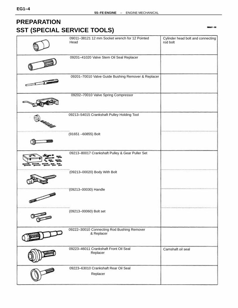
TIMING BELT REMOVAL(See Components for Removal and Installation)1. DISCONNECT NEGATIVE (–) TERMINAL CABLE
FROM BATTERYCAUTION: Work must be started after 90 seconds fromthe time the ignition switch is turned to the ’LOCK’position and the negative (–) terminal cable is discon–nected from the battery.
2. REMOVE ENGINE COOLANT RESERVOIR TANK(a) Disconnect the reservoir hose.(b) While pushing the tab of the bracket, remove the
reservoir tank.3. REMOVE GENERATOR (See page CH–10)4. REMOVE RH FRONT WHEEL5. REMOVE RH FENDER APRON SEAL
8. REMOVE ENGINE MOVING CONTROL RODRemove the 3 bolts and control rod.9. DISCONNECT CONNECTOR FROM GROUND WIRE ON RH FENDER APRON
7. SLIGHTLY JACK UP ENGINERaise the engine enough to remove the weight fromthe engine mounting on the right side.
6. REMOVE PS DRIVE BELTLoosen the 2 bolts, and remove the drive belt.
–5S–FE ENGINE ENGINE MECHANICALEG1–26

11. REMOVE SPARK PLUGS(a) Disconnect the high – tension cords at the rubber
boot.DO NOT pull on the cords.
NOTICE: Pulling on or bending the cords may damage theconductor inside.
13. SET NO.1 CYLINDER TO TDC/COMPRESSION(a) Turn the crankshaft pulley and align its groove with
timing mark “0” of the No.1 timing belt cover.
12. REMOVE NO.2 TIMING BELT COVERRemove the 5 bolts, timing belt cover and 2 gaskets.
10. REMOVE No.2 ENGINE MOUNTING BRACKETRemove the 3 bolts and mounting bracket.
(b) Using a 16 mm plug wrench, remove the spark plug.
–5S–FE ENGINE ENGINE MECHANICALEG1–27

14. REMOVE TIMING BELT FROM CAMSHAFT TIMINGPULLEY
HINT (When re–using timing belt): Place the match–marks on the timing belt and camshaft timing pulley,and place matchmark on timing belt to match the endof the No.1 timing belt cover.
15. REMOVE CAMSHAFT TIMING PULLEYUsing SST, remove the bolt, plate washer and timingpulley.SST 09249–63010 and 09278–54012
(b) Check that the hole of the camshaft timing pulley isaligned with the timing mark of the bearing cap.If not, turn the crankshaft one revolution (360’*).
(a) Loosen the mounting bolt of the No.1 idler pulley andshift the pulley toward the left as far as it will go, andtemporarily tighten it.
(b) Remove the timing belt from the camshaft timingpulley.
–5S–FE ENGINE ENGINE MECHANICALEG1–28

HINT (When re–using timing belt): After looseningthe crankshaft pulley bolt, check that the timing beltmatchmark aligns with the end of the No. 1 timing beltcover when the crankshaft pulley groove is alignedwith the timing mark “0” of the No. 1 timing belt cover.If the matchmark does not align, align as follows:
When matchmark is misaligned counterclockwise:• Align the rnatchmarks by pulling the timing belt up
on the No.1 idler pulley side while turning thecrankshaft pulley clockwise.
When matchmark is misaligned clockwise:• Align the matchmark by pulling the timing belt up
on the water pump pulley side while turning thecrankshaft pulley counterclockwise.
• After aligning the matchmark, hold the timingbelt, turn the crankshaft pulley clockwise, andalign its groove with timing mark “0” of the No.1timing belt cover.
16. REMOVE CRANKSHAFT PULLEY(a) Using SST, remove the pulley bolt.
SST 09213–54015 (91651– 60855),09330–00021
–5S–FE ENGINE ENGINE MECHANICALEG1–29

(b) Using SST, remove the pulley.SST 09213–60017 (09213–00020, 09213–00030,09213–00060)HINT (When re–using timing belt): Remove the pulleywithout turning it.
19. REMOVE TIMING BELTHINT (When re–using timing belt): Draw a directionarrow on the timing belt (in the direction of enginerevolution), and place matchmarks on the timing beltand crankshaft timing pulley.
• After aligning the matchmark, hold the timingbelt, turn the crankshaft pulley counterclockwise,and align its groove with timing mark “0” of theNo.1 timing belt cover.
17. REMOVE No.1 TIMING BELT COVERRemove the 4 bolts, timing belt cover and gasket.
18. REMOVE TIMING BELT GUIDE
–5S–FE ENGINE ENGINE MECHANICALEG1–30

TIMING BELT COMPONENTS INSPECTION1. INSPECT TIMING BELT
NOTICE:
• Do not bend, twist or turn the timing belt Inside out.
• Do not allow the timing belt to come into contactwith oil, water or steam.
22. REMOVE CRANKSHAFT TIMING PULLEYIf the pulley cannot be removed by hand, use 2 screw–drivers.HINT: Position shop rags as shown to preventdamage.
20. REMOVE NO.1 IDLER PULLEY AND TENSIONSPRINGRemove the bolt, pulley and tension spring.
23. REMOVE OIL PUMP PULLEYUsing SST, remove the nut and pulley.SST 09616–30011
21. REMOVE NO.2 IDLER PULLEYRemove the bolt and pulley.
–5S–FE ENGINE ENGINE MECHANICALEG1–31

• Do not utilize timing belt tension when installing orremoving the mounting bolt of the camshaft timingpulley.
If there are any defects as shown in the illustration,check the following points:(a) Premature parting
• Check for proper installation.
• Check the timing cover gasket for damage andproper installation.
(b) If the belt teeth are cracked or damaged, check to seeif either camshaft or water pump is locked.
(e) If there is noticeable wear on the belt teeth, check thetiming cover for damage, correct gasket installation,and for foreign material on the pulley teeth.If necessary, replace the timing belt.
(c) If there is noticeable wear or cracks on the belt face,check to see if there are nicks on the side of the idlerpulley lock.
(d) If there is wear or damage on only one side of the belt,check the belt guide and the alignment of each pulley.
–5S–FE ENGINE ENGINE MECHANICALEG1–32

3. INSPECT TENSION SPRING(a) Measure the free length of tension spring.
Free length: 46.0 mm (1.811 in.)If the free length is not as specified, replace thetension spring.
(b) Measure the tension of the tension spring at thespecified installed length.Installed tension (at 50.5 mm (1.988 in.)):Green color 32 – 37 N (3.25 – 3.75 k9f, 7.2 – 8.3 lbf)Silver color 47 – 52 N (4.75 – 5.25 kgf, 10.5 – 11.8 lbf)
If the installed tension is not as specified, replace thetension spring.
TIMING BELT INSTALLATION(See Components for Removal and Installation)1. INSTALL OIL PUMP PULLEY
(a) Align the cutouts of the pulley and shaft, and slide onthe pulley.
2. INSPECT IDLER PULLEYSCheck that the idler pulley turns smoothly.If necessary, replace the idler pulley.
(b) Using SST, install the nut.SST 09616 – 30011Torque: 28 N–m (290 kgf–cm, 21 ft–lbf)
–5S–FE ENGINE ENGINE MECHANICALEG1–33

4. TEMPORARILY INSTALL NO.1 IDLER PULLEY AND TENSION SPRING
(a) Install the pulley with the bolt. Do not tighten the boltyet.
HINT: Use a bolt 42 mm (1.65 in.) in length.(b) Install the tension spring.(c) Pry the pulley toward the left as far as it will go and
tighten the bolt.(d) Check that the idler pulley moves smoothly.
5. TEMPORARILY INSTALL TIMING BELTNOTICE: The engine should be cold.
(a) Using the crankshaft pulley bolt, turn the crankshaftand position the key groove of the crankshaft timingpulley upward.
(b) Remove any oil or water on the crankshaft pulley, oilpump pulley, water pump pulley, No. 1 idler pulley, No.2 idler pulley and keep them clean.
(c) Install the timing belt on the crankshaft timing pulley,oil pump pulley, No.1 idler pulley, water pump pulleyand No.2 idler pulley.HINT (When re–using timing belt): Align the pointsmarked during removal, and install the belt with thearrow pointing in the direction of engine revolution.
2. INSTALL CRANKSHAFT TIMING PULLEY(a) Align the timing pulley set key with the key groove of
the pulley.(b) Slide on the timing pulley, facing the flange side
inward.
3. INSTALL NO.2 IDLER PULLEY(a) Install the pulley with the bolt.Torque: 42 N–m (425 kgf–cm, 31 ft–lbf)
HINT: Use a bolt 35 mm (1.38 in.) in length.(b) Check that the idler pulley moves smoothly.
–5S–FE ENGINE ENGINE MECHANICALEG1–34

9. INSTALL CAMSHAFT TIMING PULLEY(a) Align the camshaft knock pin with the knock pin
groove of the pulley, and slide on the timing pulley.(b) Using SST, install the plate washer and bolt.
SST 09249 – 63010 and 09278 – 54012Torque: 37 N–m (380 kgf–cm, 27 ft–lbf)
HINT: Use a torque wrench with a fulcrum length of340 cm (13.39 in.)
8. INSTALL CRANKSHAFT PULLEY(a) Align the pulley set key with the key groove of the
pulley, and slide on the pulley.(b) Using SST, install the pulley bolt.
SST 09213–54015 (91651 –60855)09330–00021
Torque: 108 N–m (1,100 kgf–cm, 80 ft–lbf)
10. SET No.1 CYLINDER TO TDC/COMPRESSION(a) Turn the crankshaft pulley, and align its groove with
timing mark “0” of the No.1 timing belt cover.
7. INSTALL NO.1 TIMING BELT COVER(a) Install the gasket to the timing belt cover.(b) Install the timing belt cover with the 4 bolts.
6. INSTALL TIMING BELT GUIDEInstall the guide, facing the cup side outward.
–5S–FE ENGINE ENGINE MECHANICALEG1–35

11. INSTALL TIMING BELTHINT. (When re–using timing belt):• Check that the matchmark on the timing belt
matches the end of the No.1 timing belt cover.If the matchmark does not align, shift the meshing ofthe timing belt and crankshaft timing pulley until theyalign. (See page EG1–29)
(a) Remove any oil or water on the camshaft timingpulley, and keep it clean.
(b) Install the timing belt, and check the tension betweenthe crankshaft timing pulley and camshaft timingpulley.
(b) Using SST, turn the camshaft, and align the hole ofthe camshaft timing pulley with the timing mark of thebearing cap.SST 09278–54012
• Align the matchmarks of the timing belt andcamshaft timing pulley.
12. CHECK VALVE TIMING(a) Loosen the No.1 idler pulley bolt 1/2 turn.
–5S–FE ENGINE ENGINE MECHANICALEG1–36

13. INSTALL NO.2 TIMING BELT COVER(a) Install the 2 gaskets to the No. 1 and No.2 belt covers.(b) install the belt cover with the 5 bolts.(c) Align the 2 clamps of the engine wire with cover
mounting bolts.
(d) w/ Green Tension Spring:Slowly turn the crankshaft pulley 1 and 7/8 revolu–tions, and align its groove with the mark at 45 BTDC(for No.1 cylinder) of the No.1 timing belt cover.
NOTICE: Always turn the crankshaft clockwise.
(c) Check that each pulley aligns with the timing marks asshown in the illustration..If the timing marks do not align, remove the timingbelt and reinstall it.
(b) Turn the crankshaft pulley 2 revolutions from TDC toTDC.
NOTICE: Always turn the crankshaft clockwise.
(e) Torque the mounting bolt of the No.1 idler pulley.Torque: 42 N–m (425 kgf–cm, 31 ft–lbf)
–5S–FE ENGINE ENGINE MECHANICALEG1–37

17. INSTALL ENGINE MOVING CONTROL ROD(a) Temporarily install the engine moving control rod with
the 3 bolts in the sequence shown.
15. INSTALL NO.2 ENGINE MOUNTING BRACKET(a) Temporarily install the No.2 engine mounting bracket
with the 2 bolts.
14. INSTALL SPARK PLUGS(a) Using a 16 mm plug wrench, install the spark plug.(b) Connect the high–tension cords.
(b) Install the remaining bolt.(c) Tighten the 3 bolts in the sequence shown.Torque: 52 N–m (530 kgf–cm, 38 ft–lbf)
16. CONNECT CONNECTOR TO GROUND WIRE ON RH FENDER APRON
–5S–FE ENGINE ENGINE MECHANICALEG1–38

19. INSTALL RH FENDER APRON SEAL20. INSTALL RH FRONT WHEEL21. INSTALL GENERATOR (See page CH–24)
Drive belt tension:w/ A/C
New belt 175 ± 5 lbf Used belt 130 ± 10 lbfw/o A/C New belt 125 ± 25 lbfUsed belt 95 ± 20 lbf22. INSTALL ENGINE COOLANT RESERVOIR TANK23. CONNECT NEGATIVE (–) TERMINAL CABLE TOBATTERY
18. INSTALL AND ADJUST PS DRIVE BELTInstall the drive belt with the pivot and adjusting bolts.Drive belt tension: New belt 125 ± 25 lbf Used belt 80 ± 20 I bf
(b) Tighten the 3 bolts in the sequence shown.Torque: 64 N–m (650 kgf–cm. 47 ft–lbf)
–5S–FE ENGINE ENGINE MECHANICALEG1–39

CYLINDER HEADCOMPONENTS FOR REMOVAL ANDINSTALLATION
–5S–FE ENGINE ENGINE MECHANICALEG1–40

COMPONENTS (Cont’d)
–5S–FE ENGINE ENGINE MECHANICALEG1–41

5. REMOVE AIR CLEANER CAP, RESONATOR AND AIR CLEANER HOSE
(a) Disconnect the intake air temperature sensor connec–tor.
(b) California only:Disconnect the air hose from the air cleaner hose.
(c) Loosen the air cleaner hose clamp bolt.(d) Disconnect the 4 air cleaner cap clips.(e) Disconnect the air cleaner hose from the throttle
body, and remove the air cleaner cap together withthe resonator and air cleaner hose.
6. REMOVE GENERATOR (See page CH–10)7. REMOVE DISTRIBUTOR(See page IG–13 end 32)
CYLINDER HEAD REMOVAL(See Components for Removal and Installation)1. DISCONNECT NEGATIVE (–) TERMINAL CABLE
FROM BATTERYCAUTION: Work must be started after 90 seconds fromthe time the ignition switch is turned to the “LOCK”position and the negative (–) terminal cable is discon–nected from the battery.
2. DRAIN ENGINE COOLANT3. A/T:
DISCONNECT THROTTLE CABLE FROMTHROTTLE BODY4. DISCONNECT ACCELERATOR CABLE FROMTHROTTLE BODY
8. DISCONNECT FRONT EXHAUST PIPE(a) Loosen the 2 bolts, and disconnect the bracket.(b) Using a 14 mm deep socket wrench, remove the 3
nuts holding the front exhaust pipe to the WU–TWC.(c) Disconnect the front exhaust pipe and gaskets.
–5S–FE ENGINE ENGINE MECHANICALEG1–42

10. SEPARATE EXHAUST MANIFOLD AND WARM UPTHREE–WAY CATALYTIC CONVERTER
Remove the following parts:(1) 3 bolts(2) Manifold lower heat insulator(3) 8 bolts(4) 2 WU–TWC heat insulators
9. REMOVE EXHAUST MANIFOLD AND WARM UPTHREE–WAY CATALYTIC CONVERTER ASSEMBLY(a) Disconnect the main oxygen and sub oxygen sensor
connectors.(b) Remove the 4 bolts and upper heat insulator.
(e) Remove the 6 nuts, the exhaust manifold and WU –TWC assembly.
(c) Remove the bolt, nut and No. 1 manifold stay.
(d) Remove the bolt, nut and manifold stay.
–5S–FE ENGINE ENGINE MECHANICALEG1–43

11. DISCONNECT OIL PRESSURE SWITCHCONNECTOR
12. DISCONNECT ENGINE WIRE (FOR OXYGEN SENSORS) FROM ENGINE HANGER13. REMOVE WATER OUTLET
(a) Disconnect the following connectors:(1) Engine coolant temperature sender gauge con– nector(2) Engine coolant temperature sensor connector
(b) Disconnect the following hoses:(1) Upper radiator hose(2) Water bypass pipe hose(3) Heater water hose(4) IAC water bypass hose(5) 2 TVV (for EVAP) vacuum hoses
14. REMOVE WATER BYPASS PIPE(a) Disconnect the following hoses:
(1) IAC water bypass hose(2) Heater water hose(3) w/ Oil Cooler:2 oil cooler water bypass hoses
(5) 3 bolts and 2 nuts(6) Exhaust manifold(7) Gasket(8) Retainer(9) Cushion(10) WU–TWC
(c) Remove the 2 bolts, water outlet and gasket.
–5S–FE ENGINE ENGINE MECHANICALEG1–44

(f) Disconnect the following hoses from the throttlebody, and remove the throttle body.
(1) Water bypass hose from water outlet(2) Water bypass hose from water bypass pipe(3) California:
Air hose from cylinder headExcept California:Air hose from air tube
(c) Disconnect the following hoses from the throttlebody.
(1) PCV hose(2) 2 vacuum hoses from EGR vacuum modulator(3) Vacuum hose from TVV (for EVAP)
(b) Remove the 2 bolts, 2 nuts, water bypass pipe andgasket.
(c) Remove the O–ring from the water bypass hose.
15. REMOVE THROTTLE BODY(a) Disconnect the throttle position sensor connector.(b) Disconnect the IAC valve connector.
(d) Type A:Remove the 4 bolts.
(e) Type B:Remove the 2 bolts and 2 nuts.
–5S–FE ENGINE ENGINE MECHANICALEG1–45

17. DISCONNECT VACUUM HOSESDisconnect the following hoses:
(1) MAP sensor hose from air intake chamber(2) Brake booster vacuum hose from air intake cha–
mber(3) PS vacuum hose from air intake chamber(4) Vacuum sensing hose from fuel pressure regula–
tor 1S. W/ A/C:
DISCONNECT A/C IDLE–UP VALVE CONNECTOR19. EXCEPT CALIFORNIA: REMOVE AIR TUBE
(a) Disconnect the following hoses from the air tube:(1) w/ A/C:
Air hose from ASV(2) 2 air hoses from PS pump
I6. REMOVE EGR VALVE AND VACUUM MODULATOR(a) Disconnect the EGR gas temperature sensor connec–
tor.(b) Disconnect the following hoses:
(1) 2 vacuum hoses from VSV (for EGR) (2) Vacuum hose from charcoal canister(c) Disconnect the vacuum hose clamp.
(d) Loosen the union nut of the EGR pipe, and remove the2 nuts, EGR valve, vacuum modulator, vacuum hosesassembly and gasket.
(b) Remove the 3 bolts, wire clamp and air tube.
–5S–FE ENGINE ENGINE MECHANICALEG1–46

20. CALIFORNIA:REMOVE AIR TUBE
(a) Disconnect the following hoses:(1) w/ A/C:A/C hose (from ASV) from air tube
(2) 2 air hoses (from PS pump) from air tube(3) California only:
2 vacuum hoses from VSV (for fuel pressurecontrol)
(4) Vacuum hose from air intake chamber(b) Remove the 3 bolts, wire clamp and air tube.
21. DISCONNECT 2 ENGINE WIRE GROUND STRAPSFROM INTAKE MANIFOLD
22. DISCONNECT KNOCK SENSOR AND VSV (FOR EGR) CONNECTORS23. CALIFORNIA ONLY:
DISCONNECT VSV (FOR FUEL PRESSURE CON– TROL) CONNECTOR24. REMOVE VSV OR VSV ASSEMBLY
25. REMOVE INTAKE MANIFOLD(a) Remove the 4 bolts, wire bracket, No.1 air intake
chamber and manifold stays.(b) Remove the bolt, vacuum hose bracket, and discon–
nect the engine wire.
(c) Remove the6 bolts, 2 nuts, intake manifold andgasket.
–5S–FE ENGINE ENGINE MECHANICALEG1–47

(d) Remove the 2 bolts and delivery pipe together withthe 4 injectors.
NOTICE: Be careful not to drop the injectors when rem–oving the delivery pips.
(e) Remove the 4 insulators (except California) and 2spacers from the cylinder head.
(f) Pull out the 4 injectors from the delivery pipe.
26. REMOVE DELIVERY PIPE AND INJECTORS(a) Disconnect the injector connectors.(b) Loosen the pulsation damper, and disconnect the fuel
inlet hose.(c) Disconnect fuel return hose.
(g) California:Remove the 2 O–rings, insulator and grommet fromeach injector.
(h) Except California:Remove the 0–ring and grommet from each injector.
(d) Disconnect the 2 wire clamps from the wire bracketson the intake manifold.
–5S–FE ENGINE ENGINE MECHANICALEG1–48

NOTICE:
• Support the timing belt, :o the meshing of crank–shaft timing pulley and timing belt does not shift.
• Be careful not to drop anything inside the timingbelt cover.
• Do not allow the belt to come into correct with oil,water or dust.
30. REMOVE ENGINE HANGERSRemove the bolt and engine hanger. Remove the 2engine hangers. Remove the ground strap.31. REMOVE GENERATOR BRACKETRemove the 3 bolts and generator bracket.32. REMOVE OIL PRESSURE SWITCH
27. REMOVE CAMSHAFT TIMING PULLEY(See steps 2 to 15 on pages EG1–26 to 28)28. REMOVE NO. 1 IDLER PULLEY AND TENSIONSPRINGRemove the bolt, pulley and tension spring.
33. REMOVE CYLINDER HEAD COVERRemove the 4 nuts, grommets, head cover and gasket.
29. REMOVE NO.3 TIMING BELT COVERRemove the 4 bolts and timing and cover.
–5S–FE ENGINE ENGINE MECHANICALEG1–49

(b) Secure the exhaust camshaft sub gear to drive gearwith a service bolt.Recommended service bolt:Thread diameter6 mmThread pitch 1.0 mmBolt length 16–20 m m (0.63–0.79 in.)
HINT: When removing the camshaft, make sure thatthe torsional spring force of the sub gear has beeneliminated by the above operation.
35. REMOVE CAMSHAFTSNOTICE: Since the thrust clearance of the camshaft issmall, the camshaft must be kept level while it is beingremoved. If the camshaft is not kept level, the portion ofthe cylinder head receiving the shaft thrust may crack orbe damaged, causing the camshaft to seize or break. Toavoid this, the following steps should be carried out.
A. Remove exhaust camshaft(a) Set the knock pin of the intake camshaft at 10–45° BTDC of camshaft position.
HINT: The above angle allows No.2 and No.4 cylindercam lobes of the exhaust camshaft to push their valvelifters evenly.
HINT: Arrange the grommets in correct order, so thatthey can be reinstalled into their original positions.This minimizes any possibility of oil leakage due toreuse of grommets.
34. REMOVE HIGH – TENSION CORDS CLAMP AND PCV VALVE
–5S–FE ENGINE ENGINE MECHANICALEG1–50

(f) Alternately loosen and remove the 2 bolts on the No.3 bearing cap.
HINT:• As the 2 No.3 bearing cap bolts are loosened, make
sure that the camshaft is lifted out straight and level.• If the camshaft is not being lifted out straight and
level, retighten the 2 No.3 bearing cap bolts. Thenreverse the order of above steps from (f) to (a) andreset the knock pin of the intake camshaft at 10–45BTDC, and repeat steps from
(b) to(f) once again.NOTICE: Do not pry on or attempt to force the camshaftwith a tool or other object.
(g) Remove the No.3 bearing cap and exhaust camshaft.
(d) Uniformly loosen and remove the6 bolts on the No. 1,No.2 and No.4 bearing caps in several passes in thesequence shown.
NOTICE: Do not remove the No.3 bearing cap bolts at thisstage.
(e) Remove the No. 1, No.2 and No.4 bearing caps.
B. Remove intake camshaft(a) Set the knock pin of the intake camshaft at 80–115
BTDC of camshaft angle.HINT: The above angle allows the No.1 and No.3cylinder cam lobes of intake camshaft to push theirvalve lifters evenly.
(c) Remove the 2 bolts and rear bearing cap.
–5S–FE ENGINE ENGINE MECHANICALEG1–51

(e) Alternately loosen and remove the 2 bolts on the No.2 bearing cap.
HINT:
• As the 2 No.2 bearing cap bolts are loosened, makesure that the camshaft is lifted out straight and level,after breaking adhesion on the front bearing cap.
• If the camshaft is not being lifted out straight andlevel, retighten the 2 No.2 bearing cap bolts. Reversethe order of above steps from (e) to (a) and reset theknock pin of the intake camshaft at 80–115*6TDC,and repeat steps from (b) to (e) once again.
NOTICE: Do not pry on or attempt to force the camshaftwith a tool or other object.
(f) Remove the No.2 bearing cap and camshaft.
(c) Uniformly loosen and remove the6 bolts on the No.1,No.3 and No.4 bearing caps in several passes in thesequence shown.
NOTICE: Do not remove the No.2 bearing cap bolts at this
stage.(d) Remove the No. 1, No.3 and No.4 bearing caps.
36. DISASSEMBLE EXHAUST CAMSHAFT(a) Mount the hexagon wrench head portion of the cam–
shaft in a vise.NOTICE: Be careful not to damage the camshaft.
(b) Remove the 2 bolts, front bearing cap and oil seal.
–5S–FE ENGINE ENGINE MECHANICALEG1–52

37. REMOVE CYLINDER HEAD(a) Using SST, uniformly loosen and remove the 10 cylin–
der head bolts in several passes, in the sequenceshown.SST 09011– 38121
NOTICE: Cylinder head warpage or cracking could resultfrom removing bolts in incorrect order.
(b) Insert a service bolt (A) into the service hole of thecamshaft sub gear.
(c) Using a screwdriver, turn the sub gear clockwise, andremove the service bolt (B).
NOTICE: Be careful not to damage the camshaft.
(e) Remove the following parts:(1) Wave washer
(2) Camshaft sub gear (3) Camshaft gear spring
(d) Using snap ring pliers, remove the snap ring.
–5S–FE ENGINE ENGINE MECHANICALEG1–53

(b) Lift the cylinder head from the dowels on the cylinderblock, and place the cylinder head on wooden blockson a bench.
HINT: If the cylinder head is difficult to lift off, prybetween the cylinder head and cylinder block with ascrewdriver.
NOTICE: Be careful not to damage the contact surfacesof the cylinder head and cylinder block.
2. REMOVE VALVES(a) Using SST, compress the valve spring and remove the
2 keepers.SST 09202 – 70010
(b) Remove the spring retainer, valve spring, valve andspring seat.
CYLINDER HEAD DISASSEMBLY(See Components for Removal and Installation)1. REMOVE VALVE LIFTERS AND SHIMS
HINT: Arrange the valves, valve springs, spring seatsand spring retainers in correct order.
HINT: Arrange the valve lifters and shims in correctorder.
–5S–FE ENGINE ENGINE MECHANICALEG1–54

CYLINDER HEAD COMPONENTSINSPECTION, CLEANING AND REPAIR1. CLEAN TOP SURFACES OF PISTONS AND
CYLINDER BLOCK(a) Turn the crankshaft, and bring each piston to top dead
center (TDC). Using a gasket scraper, remove all thecarbon from the piston top surface.
(b) Using a gasket scraper, remove all the gasket material from the cylinder block surface.
(c) Using compressed air, blow carbon and oil from the bolt holes.
CAUTION: Protect your eyes when using high pressurecompressed air.
2. CLEAN CYLINDER HEADA. Remove gasket materialUsing a gasket scraper, remove all the gasket materialfrom the cylinder block contact surface.
NOTICE: Be careful not to scratch the cylinder blockcontact surface.
B. Clean combustion chambersUsing a wire brush, remove all the carbon from thecombustion chambers.
NOTICE: Be careful not to scratch the cylinder blockcontact surface.
(c) Using needle–nose pliers, remove the oil seal.
–5S–FE ENGINE ENGINE MECHANICALEG1–55

3. INSPECT CYLINDER HEADA. Inspect for flatnessUsing a precision straight edge and thickness gauge,measure the surfaces contacting the cylinder blockand the manifolds for warpage.Maximum warpage: Cylinder block side 0.05 mm (0.0020 in.) Manifold side 0.08 mm (0.0031 in.)If warpage is greater than maximum, replace the cylin–der head.
B. Inspect for cracksUsing a dye penetrant, check the combustion cham–bers, intake ports, exhaust ports and cylinder blocksurface for cracks.If cracked, replace the cylinder head.
D. Clean cylinder headUsing a soft brush and solvent, thoroughly clean thecylinder head.
C. Clean valve guide bushingsUsing a valve guide bushing brush and solvent, cleanall the guide bushings.
–5S–FE ENGINE ENGINE MECHANICALEG1–56

(c) Subtract the valve stem diameter measurement fromthe guide bushing inside diameter measurement.Standard oil clearance: Intake 0.025 – 0.060 mm (0.0010 – 0.0024 in.)Exhaust 0.030 – 0.065 mm (0.0012 – 0.0028 in.)Maximum oil clearance:Intake 0.08 mm (0.0031 in.)Exhaust 0.10 mm (0.0039 In.)If the clearance is greater than maximum, replace thevalve and guide bushing.
(b) Using a micrometer, measure the diameter of thevalve stem.Valve stem diameter:Intake5.970 – 5.985 mm (0.2350 – 0.2356 in.)Exhaust5.965 – 5.980 mm (0.2348 – 0.2354 In.)
5. INSPECT VALVE STEMS AND GUIDE BUSHINGS(a) Using a caliper gauge, measure the inside diameter of
the guide bushing.Bushing inside diameter: 6.010 –6.030 mm (0.2366 – 0.2374 in.)
4. CLEAN VALVES(a) Using a gasket scraper, chip off any carbon from the
valve head.(b) Using a wire brush, thoroughly clean the valve.
–5S–FE ENGINE ENGINE MECHANICALEG1–57

6. IF NECESSARY, REPLACE VALVE GUIDE BUSHINGS
(a) w/ Snap Ring:Insert an old valve wrapped with tape into the valveguide bushing, and break off the valve guide bushingby hitting it with a hammer. Remove the snap ring.
HINT: Wrap the tape approx. 8 mm (0.31 in.) from thevalve stem end.
NOTICE: Be careful not to damage the valve lifter hole.
(e) Select a new guide bushing (STD size or O/S 0.05).If the bushing bore diameter of the cylinder head isgreater than 11.027 mm (0.4341 in.), machine thebushing bore to the following dimension:11.050 – 11.077 mm (0.4350 – 0.4301 in.)
If the bushing bore diameter of the cylinder head is greater than 11.077 mm (0.4361 in.), replace the cylinder head.
(b) Gradually heat the cylinder head to 80–100°C (176– 212°F).
(d) Using a caliper gauge, measure the bushing bore di–ameter of the cylinder head.
(c) Using SST and a hammer, tap out the guide bushing.SST 09201–70010
Bushing bore diameter mm (in.)
11.050 – 11.077(0.4350 – 0.4361)
11.000 – 11.02710.4331 – 0.4341)
Both intake and exhaust
Use O/S 0.05
Bushing size
Use STD
–5S–FE ENGINE ENGINE MECHANICALEG1–58

(c) Check the valve head margin thickness.Standard margin thickness:0.8 – 1.2 mm (0.031 – 0.047 in.)Minimum margin thickness:0.5 mm (0.020 in.)If the margin thickness is less than minimum, replacethe valve.
7. INSPECT AND GRIND VALVES(a) Grind the valve enough to remove pits and carbon.(b) Check that the valve is ground to the correct valve
face angle.Valve face angle:44.5
(g) Using SST and a hammer, tap in a new guide bushinguntil the snap ring makes contact with the cylinderhead.SST 09201– 70010
(h) Using a sharp6 mm reamer, ream the guide bushingto obtain the standard specified clearance (See pageEG1–57) between the guide bushing and valve stem.
(f) Gradually heat the cylinder head to 80 –100 C (117 –212F).
–5S–FE ENGINE ENGINE MECHANICALEG1–59

(d) Check the valve overall length.Standard overall length:Intake 97.60 mm (3.8425 in.)Exhaust 98.45 mm (3.8760 in.)Minimum overall length:Intake 97.1 mm (3.823 in.)Exhaust 98.0 mm (3.858 in.)If the overall length is less than minimum, replace thevalve.
(b) Check the valve seating position.Apply a light coat of prussian blue (or white lead) tothe valve face. Lightly press the valve against theseat. Do not rotate valve.
(c) Check the valve face and seat for the following:If blue appears 360 around the face, the valve isconcentric. If not, replace the valve.
(e) Check the surface of the valve stem tip for wear.If the valve stem tip is worn, resurface the tip with agrinder or replace the valve.
NOTICE: Do not grind off more than minimum.
8. INSPECT AND CLEAN VALVE SEATS(a) Using a 45 carbide cutter, resurface the valve seats.
Remove only enough metal to clean the seats.
–5S–FE ENGINE ENGINE MECHANICALEG1–60

• If blue appears 360 around the valve seat, theguide and face are concentric. If not, resurfacethe seat.
• Check that the seat contact is in the middle of thevalve face with the following width:1.0 – 1.4 mm (0.039 – 0.055 in.)If not, correct the valve seat as follows:
(1) If the seating is too high on the valve face, use30 and 45 cutters to correct the seat.
(2) If the seating is too low on the valve face, use75 and 45 cutters to correct the seat.
9. INSPECT VALVE SPRINGS(a) Using a steel square, measure the deviation of the
valve spring.Maximum deviation:2.0 mm (0.079 in.)If the deviation is greater than maximum, replace thevalve spring.
(b) Using a vernier caliper, measure the free length of thevalve spring.Free length:41.96 – 41.99 mm (1.6520 – 1.6531 in.)If the free length is not as specified, replace the valvespring.
(d) Hand–lap the valve and valve seat with an abrasivecompound.
(e) After hand–lapping, clean the valve and valve seat.
–5S–FE ENGINE ENGINE MECHANICALEG1–61

B. Inspect cam lobesUsing a micrometer, measure the cam lobe height.Standard cam lobe height:Intake 42.01 – 42.11 mm (1.6539 – 1.6579 in.)Exhaust 40.06 – 40.18 mm (1.5772 – 1.5811 In.)Minimum cam lobe height: Intake 41.90 mm (1.6496 in.)Exhaust 39.95 mm (1.5728 in.)If the cam lobe height is less than minimum, replacethe camshaft.
10. INSPECT CAMSHAFTS AND BEARINGSA. Inspect camshaft for runout
(a) Place the camshaft on V – blocks.(b) Using a dial indicator, measure the circle runout at the
center journal.Maximum circle runout:
0.04 mm (0.0016 in.)If the circle runout is greater than maximum, replacethe camshaft.
(c) Using a spring tester, measure the tension of the valvespring at the specified installed length.Installed tension:
164 – 189 N (16.7 – 19.3 kgf, 36.8 – 42.5 lbf) at 34.7 mm (1.336 in.)If the installed tension is not as specified, replace thevalve spring.
C. Inspect camshaft journalsUsing a micrometer, measure the journal diameter.Journal diameter:26.959 – 28.975 mm 11.0814 – 1.0620 in.)If the journal diameter is not as specified, check the oilclearance.
–5S–FE ENGINE ENGINE MECHANICALEG1–62

E. Inspect camshaft gear springUsing a vernier caliper, measure the free distancebetween the spring ends.Free distance:22.5 – 22.9 mm (0.886 – 0.902 in.)If the free distance is not as specified, replace the gearspring.
F. Inspect camshaft journal oil clearance(a) Clean the bearing caps and camshaft journals.(b) Place the camshafts on the cylinder head.(c) Lay a strip of Plastigage across each of the camshaft
journals.
D. Inspect camshaft bearingsCheck that bearings for flaking and scoring.If the bearings are damaged, replace the bearing capsand cylinder head as a set.
(d) Install the bearing caps.(See step 4 on pages EG1–69 to 71)
Torque: 19 N–m (190 kgf–cm, 14 ft–lbf)NOTICE: Do not turn the camshaft.
(e) Remove the bearing caps.
–5S–FE ENGINE ENGINE MECHANICALEG1–63

G. Inspect camshaft thrust clearance(a) Install the camshaft.
(See step 4 on pages EG1–69 to 71)(b) Using a dial indicator, measure the thrust clearance
while moving the camshaft back and forth.Standard thrust clearance:Intake
0.045 – 0.100 mm (0.0018 – 0.0039 in.)Exhaust 0.030 – 0.085 mm (0.0012 – 0.0033 in.)Maximum thrust clearance:Intake 0.12 mm (0.0047 in.)Exhaust 0.10 mm (0.0039 in.)
If the thrust clearance is greater than maximum, re–place the camshaft. If necessary, replace the bearingcaps and cylinder head as a set.
H. Inspect camshaft gear backlash(a) Install the camshafts without installing the exhaust
cam sub gear.(See step 4 on pages EG1–69 to 71)
(b) Using a dial indicator, measure the backlash.Standard backlash: 0.020 – 0.200 mm (0.0008 – 0.0079 in.)Maximum backlash: 6.30 mm (0.0188 in.)
If the backlash is greater then maximum, replace thecamshafts.
(f) Measure the Plastigage at its widest point. Standard oil clearance: 0.025 – 0.062 mm (0.0010 – 0.0024 In.) Maximum oil clearance: 0.10 mm (0.0039 in.)If the oil clearance is greater than maximum, replacethe camshaft. If necessary, replace the bearing capsand cylinder head as a set.(g) Completely remove the Plastigage.
–5S–FE ENGINE ENGINE MECHANICALEG1–64

(c) Subtract the lifter diameter measurement from thelifter bore diameter measurement.Standard oil clearance:0.024 – 0.052 mm (0.0009 – 0.0020 in.)Maximum oil clearance:0.07 mm (0.0028 In.)If the oil clearance is greater than maximum, replacethe lifter. If necessary, replace the cylinder head.
12. INSPECT MANIFOLDSUsing a precision straight edge and feeler gauge, mea–sure the surface contacting the cylinder head for war–page.Maximum warpage: 0.30 mm (0.0 118 In.)If warpage is greater than maximum, replace the man–ifold.
11. INSPECT VALVE LIFTERS AND LIFTER BORES(a) Using a caliper gauge, measure the lifter bore diame–
ter of the cylinder head.Lifter bore diameter:31.000 – 31.018 mm (1.2205 – 1.2213 In.)
(b) Using a micrometer, measure the lifter diameter.Lifter diameter:30.966 – 30.976 mm (1.2191 – 1.2195 in.)
–5S–FE ENGINE ENGINE MECHANICALEG1–65

CYLINDER HEAD ASSEMBLY(See Components for Removal and Installation)HINT:• Thoroughly clean all parts to be assembled.
Before installing the parts, apply new engine oil to allsliding and rotating surfaces.
• Replace all gaskets and oil seals with new ones.
(c) Using SST, compress the valve spring and place the 2keepers around the valve stem.
SST 09202 – 70010
(b) Install the following parts:(1) Valve(2) Spring seat(3) Valve spring(4) Spring retainer
1. INSTALL VALVES(a) Using SST, push in a new oil seal.
SST 09201 –41020
HINT: The intake valve oil seal is brown and theexhaust valve oil seal is black.
–5S–FE ENGINE ENGINE MECHANICALEG1–66

CYLINDER HEAD INSTALLATION(See Components for Removal and Installation)1. INSTALL CYLINDER HEADA. Place cylinder head on cylinder block
(a) Place a new cylinder head gasket in position on thecylinder block.
NOTICE: Be careful of the installation direction.
(b) Place the cylinder head in position on the cylinderhead gasket.
B. Install cylinder head boltsHINT:• The cylinder head bolts are tightened in 2 progressive
steps (steps (b) and (d)).• If any cylinder head bolt is broken or deformed, re–
place it.(a) Apply a light coat of engine oil on the threads and
under the heads of the cylinder head bolts.(b) Using SST, install and uniformly tighten the 10 cylin–
der head bolts and plate washers in several passes, inthe sequence shown.SST 09011– 38121
Torque: 49 N–m (500 kgf–cm, 36 ft–lbf)
If any one of the cylinder head bolts does not meet thetorque specification, replace the cylinder head bolt.
2. INSTALL VALVE LIFTERS AND SHIMS(a) Install the valve lifter and shim.(b) Check that the valve lifter rotates smoothly by hand.
(d) Using a plastic–faced hammer, lightly tap the valvestem tip to assure proper fit.
–5S–FE ENGINE ENGINE MECHANICALEG1–67

2. INSTALL SPARK PLUG TUBES(a) Clean the cylinder head tube holes of any residua!
adhesive, oil or foreign particles. Remove any oil withkerosene or gasoline.
(b) Screw the threads of the spark plug tube coated withadhesive into the cylinder head.
(c) Using the spark plug tube nut and a 30 mm socketwrench, tighten the spark plug tubes.
Torque: 39 N–m (400 kgf–cm, 29 ft–lbf)
(b) Install the following parts: (1) Camshaft gear spring (2) Camshaft sub gear (3) Wave washer
HINT: Align the pins on the gears with the spring ends.
(d) Retighten the cylinder head bolts 90 in the sequenceshown on the previous page.
(e) Check that the painted mark is now at a 90 angle tofront.
3. ASSEMBLY EXHAUST CAMSHAFT(a) Mount the hexagon wrench head portion of the cam–
shaft in a vise.NOTICE: Be careful not to damage the camshaft.
(c) Mark the front of the cylinder head bolt head withpaint.
–5S–FE ENGINE ENGINE MECHANICALEG1–68

A. Install intake camshaft(a) Apply MP grease to the thrust portion of the cam–
shaft.(b) Place the intake camshaft at 80–115° BTDC of cam–
shaft angle, on the cylinder head.HINT: The above angle arrows the No.1 and No.3cylinder cam lobes of the intake camshaft to pushtheir valve lifters evenly.
4. INSTALL CAMSHAFTSNOTICE: Since the thrust clearance of the camshaft issmall, the camshaft must be kept level while it is beinginstalled. If the camshaft is not kept level, the portion ofthe cylinder head receiving the shaft thrust may crack orbe damaged, causing the camshaft to seize or break. Toavoid this, the following steps should be carried out.
(d) Insert a service bolt (A) into the service hole of thecamshaft sub gear.
(e) Using a screwdriver, align the holes of the camshaftmain gear and sub gear by turning camshaft sub gearclockwise, and install a service bolt (13).
NOTICE: Be careful not to damage the camshaft.
(c) Apply seal packing to the No. 1 bearing cap as shown.Seal packing: Part No.08826 –00080 or equivalent
(c) Using snap ring pliers, install the snap ring.
–5S–FE ENGINE ENGINE MECHANICALEG1–69

B. Install exhaust camshaft(a) Set the knock pin of the intake camshaft at 10–45°
BTDC of camshaft angle.HINT: The above angle allows the No.2 and No.4cylinder cam lobes of the exhaust camshaft to pushtheir valve lifters evenly.
(e) Apply a light coat of engine oil on the threads andunder the heads of the bearing cap bolts.
(f) Install and uniformly tighten the 10 bearing cap boltsin several passes, in the sequence shown.
Torque: 19 N–m (190 kgf–cm, 14 ft–lbf)
(h) Using SST, tap in the oil seal.SST 09223–4601 1
(d) Install the bearing caps in their proper locations.
(g) Apply MP grease to a new oil seal lip.
–5S–FE ENGINE ENGINE MECHANICALEG1–70

(b) Apply MP grease to the thrust portion of the cam–shaft.
(c) Engage the exhaust camshaft gear to the intake cam–shaft gear by matching the timing marks on each gear.
(d) Roll down the exhaust camshaft onto the bearingjournals while engaging gears with each other.NOTICE: There are also assembly reference marks oneach gear as shown in the Illustration. Do not use thesemarks.
5. CHECK AND ADJUST VALVE CLEARANCE(See page EG1–12)Turn the camshaft and position the cam lobe upward,and check and adjust the valve clearance.Valve clearance (Cold):Intake 0.19 – 0.29 mm (0.007 – 0.011 In.)Exhaust 0.28 – 0.38 mm (0.011 – 0.015 In.)
(e) Turn the intake camshaft clockwise or counterclockwise littleby little until the exhaust camshaft sits inthe bearing journals evenly without rocking the cam–shaft on the bearing journals.NOTICE: It is very important to replace the camshaft inthe bearing journals evenly while tightening bearing capsin the subsequent steps.
(f) Install the bearing caps in their proper locations.
(g) Apply a light coat of engine oil on the threads andunder the heads of the bearing cap bolts.
(h) Install and uniformly tighten the 10 bearing cap boltsin several passes, in the sequence shown.Torque: 19 N–m (190 kgf–cm, 14 ft–lbf)
(i) Remove the service bolt (B).
–5S–FE ENGINE ENGINE MECHANICALEG1–71

8. INSTALL CYLINDER HEAD COVER(a) Remove any old packing (FIPG) material.(b) Apply seal packing to the cylinder head as shown in the illustration.
Seal packing:Part No.08826–00080 or equivalent
6. INSTALL SEMI–CIRCULAR PLUGS(a) Remove any old packing (FIPG) material.(b) Apply seal packing to the semi–circular plug grooves.
Seal packing:Part No.08826–00080 or equivalent
7. INSTALL PCV VALVE AND HIGH–TENSION CORDS CLAMP
(c) Install the 2 semi–circular plugs to the cylinder head.
–5S–FE ENGINE ENGINE MECHANICALEG1–72

10. INSTALL GENERATOR BRACKETInstall the generator bracket with the 3 bolts.
Torque: 42 N–m (425 kgf–cm, 31 ft–lbf)
11. INSTALL ENGINE HANGERSInstall the engine hanger with the bolt. Install the 2engine hangers. Install the ground strap.
Torque: 25 N–m (250 kgf–cm, 18 ft–lbf)
(c) Install the gasket to the head cover.(d) Install the head cover with the 4 grommets and nuts.
Uniformly tighten the nuts in several passes.Torque: 23 N–m (230 kgf–cm, 17 ft–lbf)
HINT: Install the grommets so that their markings areas shown in the illustration.
9. INSTALL OIL PRESSURE SWITCHApply adhesive to 2 or 3 threads.Adhesive:Part No.08833–00080, THREE BOND 1324 or equivalent
12. INSTALL NO.3 TIMING BELT COVERInstall the timing belt cover with the 4 bolts.
Torque: 7.8 N–m (80 kgf–cm, 69 in–lbf)
–5S–FE ENGINE ENGINE MECHANICALEG1–73

13. TEMPORARILY INSTALL NO.1 IDLER PULLEY AND TENSION SPRING
(a) Install the pulley with the bolt. Do not tighten the boltyet.
HINT: Use bolt 42 mm (1.65 in.) in length.(b) Install the tension spring.(c) Pry the pulley toward the left as far as it will go and
tighten the bolt.(d) Check that the idler pulley moves smoothly.
14. INSTALL CAMSHAFT TIMING PULLEY ANDTIMING BELT
(See page EG1–33)
15. INSTALL INJECTORS AND DELIVERY PIPE(a) California:
Install new insulator and grommet to each injector.(b) Except California:
Install a new grommet to each injector.(c) California:
Apply a light coat of gasoline to 2 new 0–rings, andinstall them to each injector.
(d) Except California:Apply a light coat of gasoline to a new 0–ring, andinstall it to each injector.
(e) While turning the injector left and right, install it to thedelivery pipes. Install the 4 injectors.
–5S–FE ENGINE ENGINE MECHANICALEG1–74

(i) Check that the injectors rotate smoothly.HINT: If injectors do not rotate smoothly, the probablecause is incorrect installation of O–rings. Replace theO–rings.(j) Position the injector connector upward.
(g) Place the 4 injectors together with the delivery pipe inposition on the cylinder head.
(h) Temporarily install the 2 bolts holding the deliverypipe to the cylinder head.
(l) Connect the fuel return hose.(m) Connect the fuel inlet pipe to the delivery pipe with 2 new
gaskets and the pulsation damper.Torque: 34 N–m (350 kgf–cm, 25 ft–lbf)
(f) Install the following parts to the intake manifold: (1) 2 spacers (2) Except California:
4 new insulators
(k) Tighten the 2 bolts holding the delivery pipe to thecylinder head.
Torque: 13 N–m (130 kgf–cm, 9 ft–lbf)
–5S–FE ENGINE ENGINE MECHANICALEG1–75

(c) Install the vacuum hose bracket and engine wire har–ness with the bolt.
(d) Install the No.1 air intake chamber and manifold stays,wire bracket with the 4 bolts.14 mm head bolt
Torque: 42 N–m (425 kgf–cm, 31 ft–lbf)12 mm head boltTorque: 22 N–m (220 kgf–cm, 16 ft–lbf)
17. INSTALL VSV OR VSV ASSEMBLY18. CALIFORNIA ONLY: CONNECT VSV (FOR FUEL PRESSURE CONTROL) CONNECTOR19. CONNECT KNOCK SENSOR AND VSV (FOR EGR) CONNECTORS20. INSTALL 2 ENGINE WIRE GROUND STRAPS TO INTAKE MANIFOLD
(b) Install a new gasket and the intake manifold with the6 bolts and 2 nuts. Uniformly tighten the bolts andnuts in several passes.
Torque: 19 N–m (195 kgf–cm, 14 ft–lbf)
16. INSTALL INTAKE MANIFOLD(a) Connect the 2 wire clamps to the wire brackets on the
intake manifold.
21. CALIFORNIA:INSTALL AIR TUBE
(a) Install the air tube and wire clamp with the 3 bolts.
–5S–FE ENGINE ENGINE MECHANICALEG1–76

25. INSTALL EGR VALVE AND VACUUM MODULATOR(a) Install a new gasket and the EGR valve with the union
nut and 2 nuts.Union nut:Torque: 59 N–m (600 kgf–cm, 43 ft–lbf)
Nut:Torque: 13 N–m (130 kgf–cm, 9 ft–lbf)
(b) Install the EGR modulator to the clamp.
23. CONNECT VACUUM HOSESConnect the following hoses: (1) MAP sensor hose to air intake chamber
(2) Brake booster vacuum hose to air intake chamber(3) PS vacuum hose to air intake chamber(4) Vacuum sensing hose to fuel pressure regulator.
24. w/ A/C:CONNECT A/C IDLE–UP VALVE CONNECTOR
(b) Connect the following hoses:(1) w/ A/C:
A/C hose (from ASV) to air tube(2) 2 air hoses (from PS pump) to air tube(3) 2 vacuum hoses to VSV (for fuel pressure con–
trol)(4) Vacuum hose to air intake chamber
22. EXCEPT CALIFORNIA:INSTALL AIR TUBE
(a) Install the air tube and wire clamp with the 3 bolts.
(b) Connect the following hoses to the air tube:(1) w/ A/C:
Air hose from ASV (2) 2 air hose from PS pump
–5S–FE ENGINE ENGINE MECHANICALEG1–77

(c) Type A:Install the throttle body with the 4 bolts.
Torque: 19 N–m (195 kgf–cm, 14 ft–lbf)
HINT: Each bolt is indicated in the illustration.Bolt length:A 45 mm (1.77 in.)B 55 mm (2.17 in.)
(d) Type e:Install the throttle body with the 2 bolts and 2 nuts.
Torque: 19 N–m (195 kgf–cm, 14 ft–lbf)
(e) Connect the following hoses to the throttle body:(1) PCV hose(2) 2 vacuum hoses from EGR vacuum modulator(3) Vacuum hose from TVV (for EVAP)
(c) Connect the vacuum hose clamp.(d) Connect the following hoses:(1) Vacuum hose to charcoal canister(2) Vacuum hose (from EGR valve) to E port of VSV
(for EGR)(3) Vacuum hose (from Q port of EGR vacuum mod–
ulator) to G port of VSV (for EGR)(e) Connect the EGR gas temperature sensor connector.
26. INSTALL THROTTLE BODY(a) Connect the following hoses to the throttle body:(1) Water bypass hose from water outlet(2) Water bypass hose from water bypass pipe(3) California:
Air hose from cylinder headExcept California:Air hose from air tube
(b) Place a new gasket on the intake chamber, facing theprotrusion downward.
–5S–FE ENGINE ENGINE MECHANICALEG1–78

(b) Connect the following hoses: (1) Upper radiator hose (2) Water bypass pipe hose (3) Heater water hose (4) IAC water bypass hose (5) TVV (for EVAP) vacuum hose (from P port of
throttle body) (6) TVV (for EVAP) vacuum hose (from charcoal canister)
27. INSTALL WATER BYPASS PIPE(a) Install a new 0–ring to the bypass pipe.(b) Apply soapy water on the 0– ring.(c) Install a new gasket and the bypass pipe with the 2
nuts and 2 bolts.Torque (Nut): 8.8 N–m (90 kgf–cm. 78 in.–lbf)
28. INSTALL WATER OUTLET(a) Install a new gasket and the water outlet with the 2
bolts.Torque: 15 N–m (150 kgf–cm, 11 ft–lbf)
(d) Connect the following hoses:(1) IAC water bypass hose
(2) Heater water hose (3) w/ Oil Cooler:
2 oil cooler water bypass hoses
(f) Connect the IAC valve connector.(g) Connect the throttle position sensor connector.
–5S–FE ENGINE ENGINE MECHANICALEG1–79

31. ASSEMBLE EXHAUST MANIFOLD AND WARM UPTHREE–WAY CATALYTIC CONVERTERAssemble the following parts:
(1) WU–TWC(2) Cushion(3) Retainer(4) Gasket(5) Exhaust manifold(6) 3 bolts and 2 nutsTorque: 29 N–m (300 kgf–cm, 22 ft–lbf)
(c) Connect the following connectors:(1) Engine coolant temperature sender gauge con–
nector (2) Engine coolant temperature sensor connector
29. CONNECT ENGINE WIRE (FOR OXYGEN SENSORS) TO ENGINE HANGER30. CONNECT OIL PRESSURE SWITCH CONNECTOR
32. INSTALL EXHAUST MANIFOLD AND WARM UPTHREE–WAY CATALYTIC CONVERTER
ASSEMBLY(a) Install a new gasket, the exhaust manifold and WU –
TWC assembly with the 6 nuts. Uniformly tighten thenuts in several passes.
Torque: 49 N–m (540 kgf–cm, 36 ft–lbf)
(7) 2 converter heat insulators(8) 8 bolts(9) Manifold lower heat insulator(10) 3 bolts
–5S–FE ENGINE ENGINE MECHANICALEG1–80

33. CONNECT FRONT EXHAUST PIPE(a) Place a new gasket on the front exhaust pipe.(b) Using a 14 mm deep socket wrench, install the 3 new
nuts holding the front exhaust pipe to the WU –TWC.Torque: 62 N–m (630 kgf–cm, 46 ft–lbf)
(c) Install the bracket with the 2 bolts.34. INSTALL DISTRIBUTOR (See page IG–17 and 37)35. INSTALL GENERATOR (See page CH–24)
36. INSTALL AIR CLEANER CAP, RESONATOR AND AIR CLEANER HOSE
(a) Connect the air cleaner hose to the throttle body.(b) Install the air cleaner cap together with the resonator
and air cleaner hose.(c) California only:
Connect the air hose to the air cleaner hose.(d) Connect the intake air temperature sensor connector.
(d) Install the manifold upper heat insulator with the 4bolts.
(e) Connect the main oxygen and sub oxygen sensorconnectors.
(c) Install the No. 1 manifold stay with the bolt and nut.Torque: 42 N–m (425 kgf–cm, 31 ft–lbf)
(b) Install the manifold stay with the bolt and nut.Torque: 42 N–m (425 kgf–cm, 31 ft–lbf)
–5S–FE ENGINE ENGINE MECHANICALEG1–81

37. A/T:CONNECT AND ADJUST THROTTLE CABLE
38. CONNECT AND ADJUST ACCELERATOR CABLE39. FILL WITH ENGINE COOLANT Capacity: 6.3 liters (6.7 US qts, 5.5 Imp. qts)40. CONNECT NEGATIVE (–) TERMINAL CABLE TO
BATTERY41. START ENGINE AND CHECK FOR LEAKS42. ADJUST IGNITION TIMING(See page IG –19 and 38)Ignition timing: 10 BTDC @ idle (w/ Terminals TO and E1 connected)43. PERFORM ROAD TESTCheck for abnormal noise, shock, slippage, correct shiftpoints and smooth operation.44. RECHECK ENGINE COOLANT LEVEL AND OILLEVEL
–5S–FE ENGINE ENGINE MECHANICALEG1–82

CYLINDER BLOCKCOMPONENTS FOR ENGINE REMOVALAND INSTALLATION
–5S–FE ENGINE ENGINE MECHANICALEG1–83

–5S–FE ENGINE ENGINE MECHANICALEG1–84

ENGINE REMOVAL1. DISCONNECT NEGATIVE (–) TERMINAL CABLE
FROM BATTERYCAUTION: Work must be started after 90 seconds fromthe time the ignition switch is turned to the ’LOCK’position and the negative (–) terminal cable Is discon–nected from the battery.
2. REMOVE BATTERY AND TRAY3. REMOVE HOOD4. REMOVE ENGINE UNDER COVER5. DRAIN ENGINE COOLANT6. DRAIN ENGINE OIL7. DISCONNECT ACCELERATOR CABLE FROMTHROTTLE BODY8. A/T:DISCONNECT THROTTLE CABLE FROMTHROTTLE BODY9. REMOVE AIR CLEANER ASSEMBLY, RESONATOR AND AIR CLEANER HOSE
(a) Disconnect the intake air temperature sensor connec–tor.
(b) California only:Disconnect the air hose from the air cleaner hose.
(c) Loosen the air cleaner hose clamp bolt.(d) Disconnect the 4 air cleaner cap clips.(e) Disconnect the air cleaner hose from the throttle
body, and remove the air cleaner cap together withthe resonator and air cleaner hose.
(f) Remove the element.(g) Remove the 3 bolts and air cleaner case.
10. w/ CRUISE CONTROL SYSTEM:REMOVE CRUISE CONTROL ACTUATOR
(a) Remove the actuator cover.(b) Disconnect the actuator connector.(c) Remove the 3 bolts, and disconnect the actuator with
the bracket.11. REMOVE RADIATOR
–5S–FE ENGINE ENGINE MECHANICALEG1–85

(c) Disconnect the following connectors:(1) Igniter connector(2) California only:Ignition coil connector(3) Noise filter connector(4) 2 ground straps from LH fender apron(5) Connector from LH fender apron
12. DISCONNECT WIRES AND CONNECTORS(a) Remove the engine relay box, and disconnect the 5
connectors.(b) Connector from LH fender apron
(6) Data link connector 1(7) 2 ground straps from RH fender apron
(d) Disconnect the MAP sensor connector.
13. DISCONNECT HEATER HOSES14. DISCONNECT FUEL RETURN HOSE
CAUTION: Catch leaking fuel in a container.
–5S–FE ENGINE ENGINE MECHANICALEG1–86

17. M/T:REMOVE CLUTCH RELEASE CYLINDER WITHOUTDISCONNECTING TUBE
Remove the 4 bolts, release cylinder and tube fromthe transaxle.
15. DISCONNECT FUEL INLET HOSECAUTION: Catch leaking fuel in a container.
16. M/T:REMOVE STARTER
19. DISCONNECT VACUUM HOSES(a) MAP sensor hose from air intake chamber(b) Brake booster vacuum hose from air intake chamber
18. DISCONNECT TRANSAXLE CONTROL CABLE (S)FROM TRANSAXLE
–5S–FE ENGINE ENGINE MECHANICALEG1–87

20. DISCONNECT ENGINE WIRE FROM CABIN(a) Remove the under cover.(b) Remove the lower instrument panel.(c) Remove the glove compartment door.(d) Remove the glove compartment.(e) Disconnect the following connectors:
(1) 2 ECM connectors (2) 2 cowl wire connector
(f) Remove the 2 nuts, and pull out the engine wire fromthe cowl panel.
(c) Charcoal canister vacuum hose
–5S–FE ENGINE ENGINE MECHANICALEG1–88

21. w/ A/C:REMOVE A/C COMPRESSOR WITHOUTDISCONNECTING HOSES(a) Disconnect the A/C compressor connector.(b) Remove the drive belt.(c) Remove the 3 bolts, and disconnect the A/C compres–
sor.HINT: Put aside the compressor, and suspend it to theradiator support with a string.
24. REMOVE PS PUMP WITHOUT DISCONNECTING HOSES
(a) Disconnect the 2 air hoses from the air pipe.(b) Remove the PS drive belt.(c) Remove the 2 bolts, and disconnect the PS pump from
the engine.HINT: Put aside the pump and suspend it from thecowl with a string.
22. DISCONNECT FRONT EXHAUST PIPE(a) Loosen the 2 bolts, and disconnect the bracket.(b) Using a 14 mm deep socket wrench, remove the 3
nuts holding the front exhaust pipe to the WU–TWC.(c) Disconnect the front exhaust pipe and gaskets.
23. REMOVE DRIVE SHAFTS (See page SA–38)
25. DISCONNECT LH ENGINE MOUNTING INSULATOR M/T:Remove the 3 bolts, and disconnect the mountinginsulator.
A/T:Remove the 4 bolts, and disconnect the mountinginsulator.
–5S–FE ENGINE ENGINE MECHANICALEG1–89

30. REMOVE ENGINE AND TRANSAXLE ASSEMBLY FROM VEHICLE
(a) Lift the engine out of the vehicle slowly and carefully.NOTICE: Be careful not to hit the PS gear housing orperk/neutral position switch (A/T).
(b) Make sure the engine is clear of all wiring, hoses andcables.
(c) Place the engine and transaxle assembly onto thestand.
26. DISCONNECT RR ENGINE MOUNTING INSULATOR(a) Remove the hole plugs.(b) Remove the 3 nuts, and disconnect the mounting
insulator.
27. DISCONNECT FR ENGINE MOUNTING INSULATORRemove the 3 bolts, and disconnect the mountinginsulator.
28. ATTACH ENGINE SLING DEVICE TO ENGINE HANGERS
29. REMOVE ENGINE MOVING CONTROL RODRemove the 3 bolts and control rod.
–5S–FE ENGINE ENGINE MECHANICALEG1–90

31. A/T:REMOVE STARTER
32. SEPARATE ENGINE AND TRANSAXLEM/T (See page MX–10)A/T (See page AX1–21)
34. REMOVE FR ENGINE MOUNTING INSULATOR(a) Remove the bolt, nut and manifold stay.(b) Remove the 4 bolts and mounting insulator.
33. REMOVE N0.2 RH ENGINE MOUNTING BRACKETRemove the 3 bolts and engine mounting bracket.
35. REMOVE RR ENGINE MOUNTING INSULATOR Remove the 4 bolts and mounting insulator.
–5S–FE ENGINE ENGINE MECHANICALEG1–91

COMPONENTS FOR CYLINDER BLOCKDISASSEMBLY AND ASSEMBLY
–5S–FE ENGINE ENGINE MECHANICALEG1–92

9. REMOVE TIMING BELT AND PULLEYS10. REMOVE CYLINDER HEAD11. REMOVE WATER PUMP AND GENERATOR ADJUSTING BAR12. REMOVE OIL PAN AND OIL PUMP13. REMOVE OIL FILTER14. w/ OIL COOLER:
REMOVE OIL COOLER
4. REMOVE REAR END PLATERemove the bolt and end plate.5. INSTALL ENGINE TO ENGINE STAND FOR DISASSEMBLY6. REMOVE GENERATOR7. REMOVE DISTRIBUTOR
1. M/T:REMOVE CLUTCH COVER AND DISC
2. M/T:REMOVE FLYWHEEL3. A/T:REMOVE DRIVE PLATE
15. REMOVE KNOCK SENSORUsing SST, remove the knock sensor.SST 09816 – 30010
8. REMOVE PS PUMP BRACKETRemove the 3 bolts and PS pump bracket.
PREPARATION FOR DISASSEMBLY
–5S–FE ENGINE ENGINE MECHANICALEG1–93

2. CHECK THRUST CLEARANCES OF NO.1 AND NO.2BALANCE SHAFT OF ENGINE BALANCERUsing a dial indicator, measure the thrust clearancewhile moving the balance shaft back and forth.Standard thrust clearance:0.065 – 0.110 mm (0.0026 – 0.0043 in.)Maximum clearance:0.11 mm (0.0043 in.)If the clearance is greater than maximum, replace thebalance shaft housings and bearings. If necessary,replace the balance shafts.3. CHECK BACKLASH OF CRANKSHAFT GEAR AND
NO.1 BALANCE SHAFT GEARNOTICE:
• Backlash between the crankshaft gear and No.1balance shaft gear varies with the rotation of thebalance shaft and the deviation of the crankshaftgear.
• Accordingly, it is necessary to measure the backlashat the 4 points shown in the illustration on the left.When this inspection is performed on–vehicle, thespecifications are increased by approx. 0.025 mm(See specifications below)
CYLINDER BLOCK DISASSEMBLY(See Components for Cylinder Block Disassemblyand Assembly)1. REMOVE REAR OIL SEAL RETAINERRemove the 6 bolts, retainer and gasket.
(a) Rotate the crankshaft 2 or 3 times to settle the crank–shaft gear and No.1 balance shaft gear.
(b) When No.1 piston is at TDC, check that the punchmarks shown in the illustration of the balance shaftsare aligned with the grooves of the No.2 housing.
–5S–FE ENGINE ENGINE MECHANICALEG1–94

(f) Lightly turn the No. 1 balance shaft by hand and meas–ure the backlash.HINT:• Turn the No.1 balance shaft 4 or 5 times to
provide a steady backlash reading.• To prevent excessive backlash due to thrust cle–
arance, measure the backlash while pressing onthe rear of the No.1 balance shaft.
Standard backlash:Off–vehicle0–0.06 mm (0–0.0024 In.)On–vehicle0.025 – 0.080 mm (0.0010 – 0.0035 in.)
NOTICE: Do not turn the No.1 balance shaft strongly.
(g) Remove the dial gauge and the SST.
(e) Set the SST and the dial indicator as shown in theillustration.SST 09224– 74010
HINT: Make sure that the–needle of the dial indicator isperpendicular to the SST and that it is placed in themiddle of the third indention.
(d) 1 st turn the crankshaft clockwise, and align thegroove of the No.2 balance shaft housing with thepunch mark A of the No. 1 balance shaft.
(c) Check that the punch marks A and B are at thepositions on the No.1 balance shaft indicated in theillustration.
–5S–FE ENGINE ENGINE MECHANICALEG1–95

(p) Turn the crankshaft clockwise again to align thegroove of the No.2 housing with the punch mark B.
(q) Set the dial gauge. (See procedure in step (e))(r) Measure the backlash. (See procedure in step (f))
Standard backlash:0 – 0.06 mm (0 – 0.0024 In.)
(s) Remove the dial gauge.If even one of the 4 points measured above exceedsthe backlash specification, adjust the backlash withnew spacers.
NOTICE: Use the same size spacers for both the left andright sides.
HINT:
• Varying the spacer thickness by 0.02 mm(0.0008 in.) change the backlash by about 0.014mm (0.0006 in.).
• If the backlash is greater than permitted maxi–mum, select a thinner shim.
• If the backlash is less than the specification,select a thicker shim.
(I) Turn the crankshaft clockwise again to align thegroove of the No.2 housing with the punch mark A.
(m) Set the dial gauge. (See procedure in step (e))(n) Measure the backlash. (See procedure in step (f))
Standard backlash:0 – 0.06 mm (0 – 0.0024 in.)
(o) Remove the dial gauge.
(h) Turn the crankshaft clockwise to align the groove ofthe No.2 housing with the punch mark B.
(i) Set the dial gauge. (See procedure in step (e))(j) Measure the backlash. (See procedure in step (f))
Standard backlash:0 – 0.06 mm (0 – 0.0024 in.)
(k) Remove the dial gauge.
–5S–FE ENGINE ENGINE MECHANICALEG1–96

–5S–FE ENGINE ENGINE MECHANICALEG1–97

5. CHECK CONNECTING ROD THRUST CLEARANCEUsing a dial indicator, measure the thrust clearancewhile moving the connecting rod back and forth.Standard thrust clearance:0.160 – 0.312 mm (0.0063 – 0.0123 in.)Maximum thrust clearance:0.36 mm (0.0138 in.)If the thrust clearance is greater than maximum, re–place the connecting rod assembly. If necessary, re–place the crankshaft.6. REMOVE CONNECTING ROD CAPS AND CHECK OIL CLEARANCE
(a) Check the matchmarks on the connecting rod and capto ensure correct reassembly.
(c) Using a plastic–faced hammer, lightly tap the con–necting rod bolts and lift off the connecting rod cap.
HINT: Keep the lower bearing inserted with the con–necting rod cap.
4. REMOVE ENGINE BALANCER(a) Uniformly loosen and remove the 6 bolts in several
passes, in the sequence shown.(b) Remove the engine balancer and spacers.
(b) Using SST, remove the connecting rod cap nuts.SST 09011–38121
–5S–FE ENGINE ENGINE MECHANICALEG1–98

(e) Clean the crank pin and bearing.(f) Check the crank pin and bearing for pitting and scrat–
ches.If the crank pin or bearing is damaged, replace thebearings. If necessary, grind or replace the crankshaft.
(h) Install the connecting rod cap.(See step 6 on pages EG1–122)1st
Torque: 25 N–m (250 kgf–cm, 18 ft–lbf)
2nd Turn 90 °NOTICE: Do not turn the crankshaft.
(d) Cover the connecting rod bolts with a short piece ofhose to protect the crankshaft from damage.
(i) Remove the connecting rod cap.(See procedure (b) and (c) on the previous page)
(g) Lay a strip of Plastigage across the crank pin.
–5S–FE ENGINE ENGINE MECHANICALEG1–99

(j) Measure the Plastigage at its widest point. Standard oil clearance: STD 0.024 – 0.055 mm (0.0009 – 0.0022 in.) U/S 0.25 0.023 – 0.069 mm (0.0009 – 0.0027 in.) Maximum oil clearance: 0.08 mm (0.0031 in.)If the oil clearance is greater than maximum, replacethe bearings. If necessary, grind or replace the crank–shaft.HINT: If using a standard bearing, replace it with onehaving the same number marked on the connectingrod cap. There are 3 sizes of standard bearings,marked *11’, “2” and “3” accordingly.Standard sized bearing center wall thickness:Mark “1”1.484 – 1.488 mm (0.0584 – 0.0586 in.)Mark “2”1.488 – 1.492 mm (0.0586 – 0.0587 in.)Mark “3”1.492 – 1.498 mm (0.0587 – 0.0589 in.)
(k) Completely remove the Plastigage.
(b) Cover the connecting rod bolts with a short piece ofhose to protect the crankshaft from damage.
(c) Push the piston, connecting rod assembly and upperbearing through the top of the cylinder block.
7. REMOVE PISTON AND CONNECTING ROD ASSEMBLIES
(a) Using a ridge reamer, remove all the carbon from thetop of the cylinder.
–5S–FE ENGINE ENGINE MECHANICALEG1–100

8. CHECK CRANKSHAFT THRUST CLEARANCEUsing a dial indicator, measure the thrust clearancewhile prying the crankshaft back and forth with ascrewdriver.Standard thrust clearance: 0.020 – 0.220 mm (0.0008 – 0.0087 in.)Maximum thrust clearance: 0.30 mm l0.0118 in.)If the thrust clearance is greater than maximum, re–place the thrust washers as a set.Thrust washer thickness:2.440 – 2.490 mm 10.0961 – 0.0980 in.)
(b) Using the removed main bearing cap bolts, pry themain bearing cap back and forth, and remove the mainbearing caps, lower bearings and lower thrust wash–ers (No.3 main bearing cap only).
HINT:• Keep the lower bearing and main bearing cap
together.• Arrange the main bearing caps and lower thrust
washers in correct order.
HINT:• Keep the bearings, connecting rod and cap to–
gether.• Arrange the piston and connecting rod assembl–
ies in correct order.
9. REMOVE MAIN BEARING CAPS AND CHECK OIL CLEARANCE(a) Uniformly loosen and remove the main bearing cap
bolts in several passes, in the sequence shown.
–5S–FE ENGINE ENGINE MECHANICALEG1–101

(d) Clean each main journal and bearing.(e) Check each main journal and bearing for pitting and
scratches. If the journal or bearing is damaged, replace the bear–
ings. If necessary, grind or replace the crankshaft.
(c) Lift out the crankshaft. HINT: Keep the upper bearing and upper thrust wash– ers together with the cylinder block.
(h) Install the main bearing caps.(See step 4 on page EG1–121)
Torque: 59 N–m (600 kgf–cm, 43 ft–lbf)NOTICE: Do not turn the crankshaft.
(i) Remove the main bearing caps.(See procedure (a) and (b) on the previous page)
(f) Place the crankshaft on the cylinder block.(g) Lay a strip of Plastigage across each journal.
–5S–FE ENGINE ENGINE MECHANICALEG1–102

HINT: If replacing the cylinder block subassembly, thebearing standard clearance will be:No.3: 0.027 – 0.054 mm (0.0011 – 0.0021 in.)Others 0.017 – 0.044 mm (0.0007 – 0.0017 in.)If the oil clearance is greater than maximum, replacethe bearings. If necessary, grind or replace the crank–shaft.HINT: If using a standard bearing, replace it with onehaving the same number. If the number of the bearingcannot be determined, select the correct bearing byadding together the numbers imprinted on the cylin–der block and crankshaft, then selecting the bearingwith the same number as the total. There are 5 sizesof standard bearings, marked “1”, “2”, “3”, “4” and “5”accordingly.
Measure the Plastigage at its widest point.Standard clearance:No.3 STD 0.025 – 0.044 mm (0.0010 – 0.0017 in.) U/S 0.25 0.027 – 0.067 mm (0.0011 – 0.0026 in.)OthersSTD 0.015 – 0.034 mm (0.00015 – 0.0013 in.)U/S 0.25 0.019 – 0.059 mm (0.0007 – 0.0023 in.)Maximum clearance: 0.08 mm (0.0031 In.)
EXAMPLE: Cylinder block “2” + Crankshaft “11”= Total number 3 (Use bearing “3”)
Cylinder block
Number marked
Use bearing
Crankshaft
–5S–FE ENGINE ENGINE MECHANICALEG1–103

Reference:Cylinder block main journal bore diameter: Mark “1” 59.020 – 59.026 mm (2.32318 – 2.3239 in.) Mark “2” 59.026 – 59.032 mm (2.3239 – 2.3241 in.) Mark “3” 59.032 – 59.038 mm (2.3241 – 2.3243 in.)Crankshaft journal diameter: Mark “0” 54.998 – 55.003 mm (2.1653 – 2.1655 in.) Mark “11” 54.993–54.998 mm (2.1651 – 2.1653 in.) Mark “2” 54.988 – 54.993 mm (2.1649 – 2.1651 in.)Standard sized bearing center wall thickness:No–3 Mark “I” 1.992 – 1.995 mm (0.0784 – 0.0785 in.) Mark ’2” 1.995 – 1.998 mm (0.0785 – 0.0787 in.) Mark “3” 1.998 – 2.001 mm (0.0787 – 0.0788 in.) Mark ’4” 2.001 – 2.004 mm (0.0788 – 0.0789 in.) Mark ’5’ 2.004 – 2.007 mm (0.0789 – 0.0790 in.)Others Mark “I” 1.997 – 2.000 mm (0.0786 – 0.0787 in.) Mark ’2’ 2.000 – 2.003 mm (0.0787 – 0.0789 in.) Mark “3” 2.003 – 2.006 mm (0.0789 – 0.0790 in.) Mark ’4’ 2.006 – 2.009 mm (0.0790 – 0.0791 in.) Mark ’5’ 2.009 – 2.012 mm (0.0791 – 0.0792 in.)
(k) Completely remove the Plastigage.10. REMOVE CRANKSHAFT
(a) Lift out the crankshaft.(b) Remove the upper bearings and upper thrust washers
from the cylinder block.
–5S–FE ENGINE ENGINE MECHANICALEG1–104

CYLINDER BLOCK INSPECTION1. CLEAN CYLINDER BLOCKA. Remove gasket material
Using a gasket scraper, remove all the gasket materialfrom the top surface of the cylinder block.
B. Clean cylinder blockUsing a soft brush and solvent, thoroughly clean thecylinder block.
2. INSPECT TOP SURFACE OF CYLINDER BLOCK FOR FLATNESSUsing a precision straight edge and thickness gauge,measure the surfaces contacting the cylinder headgasket for warpage.Maximum warpage:0.05 mm (0.0020 In.)If warpage is greater than maximum, replace the cylin–der block.
3. INSPECT CYLINDER FOR VERTICAL SCRATCHESVisually check the cylinder for vertical scratches.If deep scratches are present, rebore all the 4 cylin–ders. If necessary, replace the cylinder block.
HINT: Arrange the main bearing caps, bearings andthrust washers in correct order.
–5S–FE ENGINE ENGINE MECHANICALEG1–105

Using a cylinder gauge, measure the cylinder borediameter at positions A, B and C in the thrust and axialdirections.Standard diameter: STD Mark “1” 87.000 – 87.010 mm (3.4252 – 3.4256 in.) Mark “2” 87.010 – 87.020 mm (3.4256 – 3.4260 in.) Mark “3” 87.020 – 87.030 mm (3.4260 – 3.4264 In.)
Maximum diameter: STD 87.23 mm (3.4342 in.) O/S 0.50 87.73 mm (3.4350 In.)If the diameter is greater than maximum, rebore all the 4cylinders. If necessary, replace the cylinder block.
4. INSPECT CYLINDER BORE DIAMETERHINT: There are 3 sizes of the standard cylinder borediameter, marked “1”, “2” and “3” accordingly. Themark is stamped on the top of the cylinder block.
5. REMOVE CYLINDER RIDGEIf the wear is less than 0.2 mm (0.008 in.), using aridge reamer, grind the top of the cylinder.
–5S–FE ENGINE ENGINE MECHANICALEG1–106

PISTON AND CONNECTING ROD ASSYDISASSEMBLY1. CHECK FIT BETWEEN PISTON AND PISTON PINTry to move the piston back and forth on the pistonpin.If any movement is felt, replace the piston and pin asa set.
2. REMOVE PISTON RINGS(a) Using a piston ring expander, remove the 2 compres–
sion rings.
3. DISCONNECT CONNECTING ROD FROM PISTON(a) Using a small screwdriver, pry out the 2 snap rings.
(b) Remove the 2 side rails and oil ring by hand. HINT: Arrange the rings in correct order only.
(b) Gradually heat the piston to 80–90C (176–194F).
–5S–FE ENGINE ENGINE MECHANICALEG1–107

PISTON AND CONNECTING RODINSPECTION1. CLEAN PISTON
(a) Using a gasket scraper, remove the carbon from thepiston top.
HINT:The piston and pin are a matched set.Arrange the pistons, pins, rings, connecting rodsand bearings in correct order.
(c) Using solvent and a brush, thoroughly clean thepiston.
NOTICE: Do not use a wire brush.
(c) Using plastic–faced hammer and brass bar, lightlytap out the piston pin and remove the connecting rod.
(b) Using a groove cleaning tool or broken ring, clean thepiston ring grooves.
–5S–FE ENGINE ENGINE MECHANICALEG1–108

(a) Using a micrometer, measure the piston diameter atring angles to the piston pin center line, 23.5 mm(0.925 in.) from the piston head.Piston diameter:STD Mark “I” 86.85–86.86 mm (3.4193 – 3.4197 in.) Mark “2” 86.86–86.87 mm (3.4197 – 3.4201 In.) Mark “3” 86.87 – 86.88 mm (3.4201 – 3.4205 in.)O/S 0.50 87.35 – 87.38 mm (3.4390 – 3.4402 in.)
(b) Measure the cylinder bore diameter in the thrust di–rections.(See step 4 on page EG1–106)
(c) Subtract the piston diameter measurement from thecylinder bore diameter measurement.Standard oil clearance: 0.14 – 0.16 mm (0.0055 – 0.0063 in.)Maximum oil clearance: 0.18 mm (0.0071 in.)
If the oil clearance is greater than maximum, replaceall the 4 pistons and rebore all the 4 cylinders. Ifnecessary, replace the cylinder block.HINT (Use new cylinder block): Use a piston with thesame number mark as the cylinder bore diametermarked on the cylinder block.
2. INSPECT PISTONA. Inspect piston oil clearanceHINT: There are 3 sizes of the standard piston diame–ter, marked “1”, “2” and “3” accordingly. The mark isstamped on the piston top.
–5S–FE ENGINE ENGINE MECHANICALEG1–109

(c) Using a thickness gauge, measure the end gap.Standard and gap: No.1 0.270 – 0.500 mm (0.0106 – 0.0197 in.)No.2 0.350 – 0.600 mm (0.0138 – 0.0234 in.)Oil (Side rail) 0.200 – 0.550 mm (0.0079 – 0.0217 in.)Maximum end gap:
No.1 1.10 mm (0.0433 in.) No.2 1.20 mm (0.0472 In.) Oil (Side rail) 1.15 mm (0.0453 In.)If the end gap is greater than maximum, replace thepiston ring. If the end gap is greater than maximum,even with a new piston ring, rebore all the 4 cylindersor replace the cylinder block.
B. Inspect piston ring groove clearanceUsing a thickness gauge, measure the clearance be–tween new piston ring and the wall of the piston ringgroove.Ring groove clearance:No.1 0.040 – 0.080 mm (0.0016 – 0.0031 In.)No.2 0.030 – 0.070 mm (0.0012 – 0.0028 in.)If the clearance is greater than maximum, replace thepiston.
C. Inspect piston ring end gap(a) Insert the piston ring into the cylinder bore.(b) Using a piston, push the piston ring a little beyond the
bottom of the ring travel, 115 mm (4.53 in.) from thetop of the cylinder block.
–5S–FE ENGINE ENGINE MECHANICALEG1–110

3. INSPECT CONNECTING RODA. Inspect connecting rod alignmentUsing a rod aligner and thickness gauge, check theconnecting rod alignment.• Check for bend.
Maximum bend:0.05 mm (0.0020 in.) per 100 mm (3.94 In.)If bend is greater than maximum, replace the connect–ing rod assembly.
• Check for twistMaximum twist:0.15 mm (0.0059 in.) per 100 mm (3.94 in.)If twist is greater than maximum, replace the connect–ing rod assembly.
B. Inspect piston pin oil clearance(a) Using a caliper gauge, measure the inside diameter of
the connecting rod bushing.Bushing inside diameter:22.005 – 22.017 mm (0.8663 – 0.8668 in.)
D. Inspect–piston pin fitAt 60C (140 F), you should be able to push thepiston pin into the piston pin hole with your thumb.
(b) Using a micrometer, measure the piston pin diameter.Piston pin diameter:21.997 – 22.009 mm (0.8660 – 0.8865 in.)
–5S–FE ENGINE ENGINE MECHANICALEG1–111

(c) Subtract the piston pin diameter measurement fromthe bushing inside diameter measurement.Standard oil clearance:0.005 – 0.011 mm (0.0002 – 0.0004 in.)Maximum oil clearance:0.05 mm (0.0020 In.)If the oil clearance is greater than maximum, replacethe bushing. If necessary, replace the piston andpiston pin as a set.
(b) Align the oil holes of a new bushing and the connect–ing rod.
(c) Using SST and a press, press in the bushing. SST 09222–30010
(e) Check the piston pin fit at normal room temperature.Coat the piston pin with engine oil, and push it into theconnecting rod with your thumb.
(d) Using a pin hole grinder, hone the bushing to obtainthe standard specified clearance (see step B above)between the bushing and piston pin.
C. If necessary, replace connecting rod bushing(a) Using SST and a press, press out the bushing.
SST 09222 – 30010
–5S–FE ENGINE ENGINE MECHANICALEG1–112

(b) If the cap nut cannot be turned easily, measure theoutside diameter of the connecting rod bolt with avernier caliper.Standard outside diameter: 7.860–8.000 mm (0.3094–0.3150 in.)Minimum outside diameter: 7.60 mm (0.2992 in.)
HINT: If the location of this area cannot be judged byvisual inspection, measure the outer diameter at thelocation shown in the illustration.If the outside diameter is less than minimum, replacethe connecting rod bolt and nut as a set.
D. Inspect connecting rod bolts(a) Install the cap nut to the connecting rod bolt. Check
that the cap nut can be turned easily by hand to theend of the thread.
–5S–FE ENGINE ENGINE MECHANICALEG1–113

2. CALCULATE AMOUNT TO BORE CYLINDERS(a) Using a micrometer, measure the piston diameter at
right angles to the piston pin center line, 23.5 mm(0.925 in.) from the piston head.
(b) Calculate the amount of each cylinder is to be reboredas follows:Size to be rebored = P + C–HP = Piston diameterC = Piston clearance0.14 – 0.18 mm (0.0055 – 0.0063 in.)H = Allowance for honing0.20 mm (0.0008 in.) or less
3. BORE AND HONE CYLINDER TO CALCULATEDDIMENSIONS
Maximum honing:0.02 mm (0.0008 in.)
NOTICE: Excess honing will destroy the finished round–ness.
CYLINDER BORINGHINT:• Bore all the 4 cylinders for the oversized piston
outside diameter.• Replace all the piston rings with ones to match
the oversized pistons.1. KEEP OVERSIZED PISTONSOversized piston diameter:O/S 0.5087.35 – 87.38 mm (3.4390–3.4402 in.)
–5S–FE ENGINE ENGINE MECHANICALEG1–114

CRANKSHAFT INSPECTION AND REPAIR1. INSPECT CRANKSHAFT FOR RUNOUT
(a) Place the crankshaft on V–blocks.(b) Using a dial indicator, measure the circle runout at the
center journal.Maximum circle runout: 0.06 mm (0.0024 In.)If the circle runout is greater than maximum, replacethe crankshaft.
2. INSPECT MAIN JOURNALS AND CRANK PINS(a) Using a micrometer, measure the diameter of each
main journal and crank pin.Main journal diameter:STD size 54.988 – 55.003 mm (2.1653–2.1655 in.)U/S 0.25 54.745 – 54.755 mm (2.1553–2.1557 in.)Crank pin diameter:STD size 51.985 – 52.000 mm (2.0466–2.0472 in.)U/S 0.25 51.745 – 51.755 mm (2.0372–2.0376 in.)
If the diameter is not as specified, check the oil clear–ance (See pages EG1–98 to 104). If necessary, grindor replace the crankshaft.
(b) Check each main journal and crank pin for taper andout–of–round as shown.Maximum taper and out–of–round:0.02 mm (0.0008 in.)If the taper and out–of–round is greater than maxi–mum, replace the crankshaft.
3. IF NECESSARY. GRIND AND HONE MAIN JOUR–NALS AND/OR CRANK PINS
Grind and hone the main journals and/or crank pins tothe finished undersized diameter (See procedure instep 2).Install new main journal and/or crankshaft pin under–sized bearings.
–5S–FE ENGINE ENGINE MECHANICALEG1–115

B. If oil pump is installed to the cylinder block:(a) Using a knife, cut off the oil seal lip.(b) Using a screwdriver, pry out the oil seal.NOTICE: Be careful not to damage the crankshaft. Tapethe screwdriver tip.
CRANKSHAFT OIL SEALSREPLACEMENTHINT: There are 2 methods (A and B) to replace the oilseal which are as follows:
(b) Using SST and a hammer, tap in a new oil seal until itssurface is flush with the oil pump case edge.SST 09223 – 63010
(c) Apply MP grease to the oil seal lip.
1. REPLACE CRANKSHAFT FRONT OIL SEALA. If oil pump is removed from cylinder block:
(a) Using a screwdriver and a hammer, tap out the oilseal.
(c) Apply MP grease to a new oil seal lip.(d) Using SST and a hammer, tap in the oil seal until its
surface is flush with the oil pump case edge.SST 09226 –10010
–5S–FE ENGINE ENGINE MECHANICALEG1–116

(b) Using SST and a hammer, tap in a new oil seal until itssurface is flush with the rear oil seal edge.SST 09223–63010
(c) Apply MP grease to the oil seal lip.
B. If rear oil seal retainer Is installed to cylinder block:(a) Using a knife, cut off the oil seal lip.(b) Using a screwdriver, pry out the oil seal.NOTICE: Be careful not to damage the crankshaft. Tapethe screwdriver tip.
2. REPLACE CRANKSHAFT REAR OIL SEALA. If rear oil seal retainer is removed from cylinder
block:(a) Using screwdriver and hammer, tap out the oil seal.
(c) Apply MP grease to a new oil seal lip.(d) Using SST and a hammer, tap in the oil seal until its
surface is flush with the rear oil seal retainer edge.SST 09223 – 63010
–5S–FE ENGINE ENGINE MECHANICALEG1–117

PISTON AND CONNECTING RODASSEMBLY1. ASSEMBLE PISTON AND CONNECTING ROD
(a) Install a new snap ring on one side of the piston pinhole.
(c) Coat the piston pin with engine oil.(d) Align the front marks of the piston and connecting
rod, and push in the piston pin with your thumb.
(e) Install a new snap ring on the other side of the pistonpin hole.
2. INSTALL PISTON RINGS(a) Install the oil ring expander and 2 side rails by hand.
(b) Gradually heat the piston to 80–90C(176–194F).
–5S–FE ENGINE ENGINE MECHANICALEG1–118

CYLINDER BLOCK ASSEMBLY(See Components for Cylinder Block Disassembly andAssembly)HINT:• Thoroughly clean all parts to be assembled.• Before installing the parts, apply new engine oil
to all sliding and rotating surfaces.• Replace all gaskets, 0–rings and oil seals with
new parts.1. INSTALL MAIN BEARINGSHINT:• Main bearings come in widths of 19.2 mm (0.756
in.) and 22.9 mm (0.902 in.). Install the 22.9 mm(0.902 in.) bearings in the No.3 cylinder blockjournal position with the main bearing cap. Installthe 19.2 mm (0.756 in.) bearings in the otherpositions.
(b) Using a piston ring expander, install the 2 compres–sion rings with the code mark facing upward.Code mark:
N o.1 1N orT No.2 2N or 2T
3. INSTALL BEARINGS(a) Align the bearing claw with the groove of the connect–
ing rod or connecting cap.(b) Install the bearings in the connecting rod and con–
necting rod cap.
(c) Position the piston rings so that the ring ends are asshown.
NOTICE: Do not align the ring ends.
–5S–FE ENGINE ENGINE MECHANICALEG1–119

(b) Align the bearing claw with the claw groove of themain bearing cap, and push in the 5 lower bearings.
HINT: A number is marked on each main bearing capto indicate the installation position.
2. INSTALL UPPER THRUST WASHERSInstall the 2 thrust washers under the No.3 journalposition of the cylinder block with the oil groovesfacing outward.
(a) Align the bearing claw with the claw groove of thecylinder block, and push in the 5 upper bearings.
• Upper bearings have an oil groove and oil holes;lower bearings do not.
3. PLACE CRANKSHAFT ON CYLINDER BLOCK
–5S–FE ENGINE ENGINE MECHANICALEG1–120

(f) Check the crankshaft thrust clearance.Using a dial indicator, measure the thrust clear–ance while prying the crankshaft back an forthwith a screwdriver.Standard thrust clearance:0.020 – 0.220 mm (0.0008 – 0.0087 in.)Maximum thrust clearance:0.30 mm (0.0118 In.)If the thrust clearance is greater than maximum, re–place the thrust washers as a set.
5. INSTALL PISTON AND CONNECTING ROD ASSEMBLES
(a) Cover the connecting rod bolts with a short piece ofhose to protect the crankshaft from damage.
(c) Apply a light coat of engine oil on the threads andunder the heads of the main bearing cap bolts.
(d) Install and uniformly tighten the 10 bolts of the mainbearing caps in several passes, in the sequenceshown.
Torque: 59 N–m (600 kgf–cm, 43 ft–lbf)
(e) Check that the crankshaft turns smoothly.
4. INSTALL MAIN BEARING CAPS AND LOWER THRUST WASHERS
(a) Install the 2 thrust washers on the No.3 bearing capwith the grooves facing outward.
(b) Install the 5 main bearing caps in their proper loca–tions.
HINT: Each bearing cap has a number and front mark.
–5S–FE ENGINE ENGINE MECHANICALEG1–121

(a) Apply a light of engine oil on the threads and underthe nuts of the connecting rod cap.
(b) Using SST, install and alternately tighten the cap nutsin several passes.SST 09011– 38121
Torque: 25 N–m (250 kgf–cm, 18 ft–lbf)If any one of the cap nuts does not meet the torquespecification, replace the connecting rod bolt and capnut as a set.
B. Install connecting rod cap nutsHINT:The cap nuts are tightened in 2 progressive steps(steps
(b) and(d)).
If any one of the connecting rod bolts is broken ordeformed, replace it.
6. INSTALL CONNECTING ROD CAPSA. Place connecting rod cap on connecting rod
(a) Match the numbered connecting rod cap with theconnecting rod.
(b) Install the connecting rod cap with the front markfacing forward.
(b) Using a piston ring compressor, push the correctlynumbered piston and connecting rod assembliesintoeach cylinder with the front mark of the piston fac-ingforward.
(c) Mark the front of the cap nut with the paint.
–5S–FE ENGINE ENGINE MECHANICALEG1–122

(g) Check the connecting rod thrust clearance.Using a dial indicator, measure the thrust clear–ance while moving the connecting rod back anforth.Standard thrust clearance:0.160 – 0.312 mm (0.0063 – 0.0123 In.)Maximum thrust clearance:0.35 mm 10.0138 In.)If the thrust clearance is greater than maximum, re–place the connecting rod assembly. If necessary, re–place the crankshaft.
(d) Retighten the cap nuts 90 as shown.(e) Check that the painted mark is now at a 90 angle to
the front.(f) Check that the crankshaft turns smoothly.
7. INSTALL ENGINE BALANCER(a) Turn the crankshaft, and set the No. 1 cylinder TDC as
shown in the illustration.
(b) Set the balance shafts so that the punch marks of thebalance shafts are aligned with the grooves of theNo.2 housing.
–5S–FE ENGINE ENGINE MECHANICALEG1–123

(h) Recheck that the punch marks of the balance shaftsare aligned with the grooves of No.2 housing.
8. CHECK AND ADJUST BACKLASH OF CRANKSHAFT GEAR AND NO.1 BALANCE SHAFT GEAR (See page EG1–94)
(c) Wipe clean the installation surface of the spacer.(d) Place the spacers on the cylinder block.
HINT: When replacing the crankshaft and/or balanceshaft, use the thickest spacers.
(e) Place the engine balancer on the cylinder block.(f) Check that punch marks shown in the illustration of
the balance shafts are align with the grooves of theNo.2 housing.
(g) While pulling the center part of the engine balancerin the direction of the arrow, uniformly tighten the6bolts in several passes, in the sequence shown.
Torque: 49 N–m (500 kgf–cm, 36 ft–lbf)
9. INSTALL REAR OIL SEAL RETAINERInstall a new gasket and the retainer with the 6 bolts.
Torque: 9.3 N–m (95 kgf–cm, 82 in.–lbf)
–5S–FE ENGINE ENGINE MECHANICALEG1–124

2. w/ OIL COOLER:INSTALL OIL COOLER
3. INSTALL OIL FILTER4. INSTALL OIL PUMP AND OIL PAN5. INSTALL WATER PUMP AND GENERATOR ADJUSTING BAR6. INSTALL CYLINDER HEAD7. INSTALL PULLEYS AND TIMING BELT
POST ASSEMBLY
1. INSTALL KNOCK SENSOR
Using SST, install the knock sensor.SST 09816–30010
Torque: 37 N–m (380 kgf–cm. 27 ft–lbf)
8. INSTALL PS PUMP BRACKETInstall the PS pump bracket with 3 bolts.
Torque: 43 N–m (440 kgf–cm, 32 ft–lbf)
9. INSTALL GENERATOR10. INSTALL DISTRIBUTOR11. REMOVE ENGINE STAND
12. INSTALL REAR END PLATETorque: 9.3 N–m (95 kgf–cm, 82 in.–lbf)
–5S–FE ENGINE ENGINE MECHANICALEG1–125

13. M/T:INSTALL FLYWHEEL
(a) Apply adhesive to 2 or 3 threads of the mounting boltend.Adhesive:Part No.08833–00070. THREE BOND 1324 or equi–valent
14. A/T:INSTALL DRIVE PLATE (See procedure step 13)
Torque: 83 N–m (850 kgf–cm, 61 ft–lbf)
15. M/T:INSTALL CLUTCH DISC AND COVER
(b) Install the flywheel on the crankshaft.(c) install and uniformly tighten the mounting bolts in
several passes, in the sequence shown.Torque: 88 N–m (900 kgf–cm, 66 ft–lbf)
–5S–FE ENGINE ENGINE MECHANICALEG1–126

ENGINE INSTALLATION
(See Components for Engine Removal and Installation)1. INSTALL RR ENGINE MOUNTING INSULATORInstall the mounting insulator with the 4 bolts.
Torque: 64 N–m (650 kgf–cm. 47 ft–lbf)
2. INSTALL FR ENGINE MOUNTING INSULATOR(a) Install the mounting insulator with the 4 bolts.Torque: 77 N–m (790 kgf–cm. 57 ft–lbf)
(b) Install the manifold stay with the bolt and nut.Torque: 42 N–m (425 kgf–cm, 31 ft–lbf)
4. ASSEMBLE ENGINE AND TRANSAXLEM/T (See page MX–15)A/T (See page AX1–27)5. A/T:INSTALL STARTER
(b) Install the remain bolt.(c) Tighten the 3 bolts in the sequence shown.Torque: 52 N–m (530 kgf–cm, 38 ft–lbf)
3. INSTALL N0.2 ENGINE MOUNTING BRACKET(a) Temporarily install the No.2 engine mounting bracket
with the 2 bolts.
–5S–FE ENGINE ENGINE MECHANICALEG1–127

6. INSTALL ENGINE AND TRANSAXLE ASSEMBLY IN VEHICLE
(a) Attach the engine sling device to the engine hangers.(b) Lower the engine into the engine compartment.
Tilt the transaxle downward, lower the engine andclear the LH mounting.
NOTICE: Be careful not to hit the PS gear housing orpark/neutral position switch (A/T).
7. INSTALL ENGINE MOVING CONTROL ROD(a) Temporarily install the engine moving control rod with
the 3 bolts in the sequence shown.
8. CONNECT FR ENGINE MOUNTING INSULATORConnect the mounting insulator with the 3 bolts.
Torque: 80 N–m (820 kgf–cm. 59 ft–lbf)
(c) Keep the engine level, and align RH and LH mountingswith the body bracket.
(b) Tighten the 3 bolts in the sequence shown.Torque: 64 N–m (650 kgf–cm, 47 ft–lbf)
–5S–FE ENGINE ENGINE MECHANICALEG1–128

9. CONNECT RR ENGINE MOUNTING INSULATOR(a) Connect the mounting insulator with the 3 nuts.Torque: 66 N–m (670 kgf–cm, 48 ft–lbf)
(b) Install the hole plugs:
12. INSTALL PS PUMP(a) Install the PS pump with the 2 bolts.Torque: 43 N–m (440 kgf–cm. 31 ft–lbf)
(b) Install the drive belt.(c) Connect the 2 air hoses to the air pipe.
10. CONNECT LH ENGINE MOUNTING INSULATORM/T:Connect the mounting insulator with the 3 bolts.
Torque: 64 N–m (650 kgf–cm, 47 ft–lbf)
A/T:Connect the mounting insulator with the 4 bolts.
Torque: 64 N–m (650 kgf–cm, 47 ft–lbf)
11. REMOVE ENGINE SLING DEVICE
13. INSTALL DRIVE SHAFTS(See page SA–40)
–5S–FE ENGINE ENGINE MECHANICALEG1–129

16. CONNECT ENGINE WIRE TO CABIN(a) Push in the engine wire through the cowl panel. Install
the 2 nuts.(b) Connect the following connectors:(1) 2 ECM connectors(2) 2 cowl wire connectors(c) Install the glove compartment.(d) Install the glove compartment door.(e) Install the lower instrument panel.(f) Install the under cover.
14. CONNECT FRONT EXHAUST PIPE(a) Place a new gasket on the front exhaust pipe.(b) Using a 14 mm deep socket wrench, install the 3 new
nuts holding the front exhaust pipe to the WU–TWC.Torque: 82 N–m (630 kgf–cm, 46 ft–lbf)
(c) Install the bracket with the 2 bolts.
15. w/ A/C:INSTALL A/C COMPRESSOR(a) Install the compressor with the 3 bolts.Torque: 27 N–m (280 kgf–cm, 20 ft–lbf)
(b) Install the drive belt.(c) Connect the A/C compressor connector.
–5S–FE ENGINE ENGINE MECHANICALEG1–130

19. M/T:INSTALL CLUTCH RELEASE CYLINDERInstall the release cylinder and tube with the 4 bolts.20. M/T:INSTALL STARTER
17. CONNECT VACUUM HOSES(a) MAP sensor hose to air intake chamber(b) Brake booster vacuum hose to air intake chamber
18. CONNECT TRANSAXLE CONTROL CABLE(S) TO TRANSAXLE
(c) Charcoal canister vacuum hose
–5S–FE ENGINE ENGINE MECHANICALEG1–131

(d) Connect the following connectors:(1) Igniter connector(2) California only:Ignition coil connector(3) Noise filter connector(4) 2 ground straps from LH fender apron(5) Connector from LH fender apron
24. CONNECT WIRES AND CONNECTORS(a) Connect the 5 connectors to the relay box.(b) Connectors from LH fender apron.(c) Install the engine relay box.
21. CONNECT FUEL INLET HOSETorque: 29 N–m (300 kgf–cm, 22 ft–lbf)
22. CONNECT FUEL RETURN HOSE23. CONNECT HEATER HOSES
–5S–FE ENGINE ENGINE MECHANICALEG1–132

27. INSTALL AIR CLEANER ASSEMBLY, RESONATOR AND AIR CLEANER HOSE
(a) Install the air cleaner case with 3 bolts.(b) Install the element.(c) Connect the air cleaner hose to the throttle body.(d) Install the air cleaner cap together with the resonator
and air cleaner hose.(e) California only:
Connect the air hose to the air cleaner hose.(f) Connect the intake air temperature sensor connector.
28. A/T:CONNECT AND ADJUST THROTTLE CABLE
29. CONNECT AND ADJUST ACCELERATOR CABLE30. FILL WITH ENGINE COOLANT31. FILL WITH ENGINE OIL32. CONNECT NEGATIVE (–) TERMINAL CABLE TO BATTERY33. START ENGINE AND CHECK FOR LEAKS34. PREFORM ENGINE ADJUSTMENT35. INSTALL ENGINE UNDER COVERS36. INSTALL HOOD37. PERFORM ROAD TESTCheck for abnormal noises, shock, slippage, correctshift points and smooth operation.38. RECHECK ENGINE COOLANT AND ENGINE OIL LEVELS
26. w/ CRUISE CONTROL SYSTEM:INSTALL CRUISE CONTROL ACTUATOR(a) Install the actuator and bracket with the 3 bolts.(b) Connect the actuator connector.(c) Install the actuator cover.
(6) Data link connector 1(7) 2 ground straps from RH fender apron(e) Connect the MAP sensor connector.
25. INSTALL RADIATOR
–5S–FE ENGINE ENGINE MECHANICALEG1–133

BALANCE SHAFT BACKLASHADJUSTMENT ON VEHICLE1. CHECK BACKLASH OF CRANKSHAFT GEAR AND
NO.1 BALANCE SHAFT GEARNOTICE: Backlash between the crankshaft gear and No.1balance shaft gear varies with the rotation of the balanceshaft and the deviation of the crankshaft gear.Accordingly, it is necessary to measure the backlash atthe 4 points shown in the illustration on the left.
(a) Rotate the crankshaft 2 or 3 times to settle the crank–shaft gear and No. 1 balance shaft gear.
(b) When No.1 piston is at TDC, check that the punchmarks C shown in the illustration of the balance shaftsare aligned with the grooves of the No. 2 housing.
(d) First turn the crankshaft clockwise, and align thegroove of the No.2 balance shaft housing with thepunch mark A of the No. 1 balance shaft.
(c) Check that the punch marks A and B are at thepositions on the No.1 balance shaft indicated in theillustration.
–5S–FE ENGINE ENGINE MECHANICALEG1–134

(f) Gently turn the No.1 balance shaft by hand, untilresistance is felt, and measure the backlash.
HINT:• Rotate the No. 1 balance shaft 4 or 5 times to
provide a steady backlash reading.• To prevent excessive backlash due to thrust cle–
arance, measure the backlash while pressing onthe rear of the No.1 balance shaft.Standard backlash (use SST): 0.060 – 0.100 mm (0.0024 – 0.0039 In.)
NOTICE: Do not turn the No.1 balance shaft strongly.
(g) Remove the dial gauge and the SST.
(h) Turn the crankshaft clockwise to align the groove ofthe No.2 housing with the punch mark B.
(i) Set the dial gauge. (See procedure in step (e))(j) Measure the backlash. (See procedure in step (f)) Standard backlash ( use SST ):
0.080 – 0.100 mm (0.0024 – 0.0039 in.)(k) Remove the dial gauge.
(e) Position the SST and dial indicator as shown in theillustration.SST 09224 – 74010
HINT: Make sure that the stem of the dial indicator isperpendicular to the SST and that it is placed in themiddle of the 3rd indentation.
–5S–FE ENGINE ENGINE MECHANICALEG1–135

(p) Turn the crankshaft clockwise again to align thegroove of the No.2 housing with the punch mark B.
(q) Set the dial gauge. (See procedure in step (e))(r) Measure the backlash. (See procedure in step (f))
Standard backlash( use SST ): 0.06 – 0.100 mm (0.0024 – 0.0039 in.)(s) Remove the dial gauge.
If even one of the 4 points measured above exceedsthe backlash specification, adjust the backlash withnew spacers.
NOTICE: Use the same size spacers for both the left andright sides.
HINT:• Varying the spacer thickness by 0.02 mm
(0.0008 in.) changes the backlash by about 0.042mrn (0.0017 in.).
• If the backlash is greater than permitted maxi–mum, select a thinner shim.
• If the backlash is less than the specification,select a thicker shim.
(I) Turn the crankshaft clockwise again to align thegroove of the No.2 housing with the punch mark A.
(m) Set the dial gauge. (See procedure in step (e))(n) Measure the backlash. (See procedure in step (f))
Standard backlash ( use SST ):0.060 – 0.100 mm (0.0024 – 0.0039 in.)
(o) Remove the dial gauge.
–5S–FE ENGINE ENGINE MECHANICALEG1–136

–5S–FE ENGINE ENGINE MECHANICALEG1–137

3. TORQUE BALANCESHAFT ASSEMBLYWhile pulling the center part of the engine balancer inthe direction of the arrow, uniformly tighten the6bolts in several passes, in the sequence shown.
Torque: 49 N–m (500 kgf–cm, 36 ft–lbf)
4. CHECK AND ADJUST BACKLASH OF CRANK–SHAFT GEAR AND No.1 BALANCE SHAFT GEAR(See procedure in step 1)
2. REPLACE THE SPACERS(a) Uniformly loosen the6 bolts in the sequence shown.(b) Replace the spacers with new ones.
–5S–FE ENGINE ENGINE MECHANICALEG1–138

EXHAUST SYSTEMCOMPONENTS
–5S–FE ENGINE ENGINE MECHANICALEG1–139

WarpageCylinder block sideManifold sideValve seatRefacing angleContacting angleContacting width
SERVICE SPECIFICATIONSSERVICE DATA
DeviationFree lengthInstalled tension et 34.7 mm (1.366 in.)
Free lengthInstalled load at 50.5 mm (1.988 in.)
Inside diameterOutside diameter (for repair part)
Lifter diameterLifter bore diameterOil clearance
Difference of pressure between each cylinder
Vale face angleStem diameter
Idler pulleytension spring
Intakemanifoldvacuum
Compressionpressure
Valve guidebushing
Valve overall length
Stem oil clearance
Margin thickness
Cylinderhead
at idle speed
Valve spring
et 250 rpm
Idle speed
Valve lifter
WarpageManifold
Valve
–5S–FE ENGINE ENGINE MECHANICALEG1–140

Cylinder head surface warpageCylinder bore diameter
Journal diameterCircle runoutCam lobe height
Camshaft gear spring end free distance
Piston ring groove clearance
Camshaft gear backlash
Piston andpiston ring
Piston ring end gap
Journal oil clearance
Piston oil clearance
Thrust clearance
Piston diameter
Cylinder block
Camshaft
–5S–FE ENGINE ENGINE MECHANICALEG1–141

Rod bendRod twistBushing inside diameterPiston pin diameterPiston pin oil clearanceConnecting rod bolt outside diameter
Circle runoutMain journal taper and out–of–roundCrank pin taper and out–of–round
Connecting rod bearing center wall thickness(Reference)
Main bearing center wall thickness (Reference)
Thrust washer thicknessMain journal oil clearance
Connecting rod oil clearance
Main journal diameter
Connectingrod
Crank pin diameter
Thrust clearance
Thrust clearanceCrankshaft
–5S–FE ENGINE ENGINE MECHANICALEG1–142

BacklashCrankshaft x No. 1 balance shaftOff–vehicleOn–vehicleNo. 1 balance shaft x No.2 balance shaftat D markat E markat F markSpacer thickness
Engine moving control rod x No. 2 engine mounting bracket
Camshaft timing pulley x Camshaft (For use with SST)
TORQUE SPECIFICATIONS
No. 2 engine mounting bracket x Cylinder block
Balance shaft housing bolt outer diameter
Engine moving control rod X Fender apron
Oil pump pulley x Oil pump drive ’shaft
Cylinder head cover x Cylinder head
Cylinder head x Cylinder block (1 sty
Camshaft timing pulley x Camshaft
No. 2 idler pulley x Cylinder block
No. 1 idler pulley x Cylinder heed
Crankshaft pulley x Crankshaft
Spark plug x Cylinder head
Enginebalancer
Thrust clearance
Part tightened
–5S–FE ENGINE ENGINE MECHANICALEG1–143

No. 1 balance shaft housing x No. 2 balance shaft housing (1st)
No. 1 balance shaft housing x No. 2 balance shaft housing (2nd)
FR engine mounting insulator x Front suspension member
RR engine mounting insulator x Front suspension member
Exhaust manifold stay x FR engine mounting insulator
No. 1 air intake chamber stay x Intake manifold
RR engine mounting insulator x Cylinder block
FR engine mounting insulator x Cylinder block
No. 1 air intake chamber stay x Cylinder head
No. 1 exhaust manifold stay x Cylinder block
Connecting rod cap x Connecting rod (2nd)
Connecting rod cap x Connecting rod (1 st)
LH engine mounting insulator x Transaxle
No. 1 exhaust manifold stay x WU –TWC
Water bypass pipe x Water pump cover
Fuel inlet hose x Fuel filter (Union bolt)
No. 3 timing belt cover x Cylinder head
Intake manifold stay x Intake manifold
Camshaft bearing cap x Cylinder head
Intake manifold stay x Cylinder block
Cylinder head x Cylinder block (2nd)
Rear oil seal retainer x Cylinder block
Exhaust manifold stay x WU –TWC
PS pump bracket x Cylinder block
Main bearing cap x Cylinder block
Generator bracket x Cylinder head
A/C compressor x Cylinder block
Pulsation damper x Delivery pipe
Exhaust manifold x Cylinder head
Engine balancer x Cylinder block
Front exhaust pipe x WU –TWC
Spark plug tube x Cylinder head
Rear end plate x Cylinder block
Throttle body x Intake manifold
Intake manifold x Cylinder heed
Engine hanger x Cylinder head
Drive plate x Crankshaft (A/T)
Knock sensor x Cylinder block
Delivery pipe x Cylinder head
PS pump x PS pump bracket
WU–TWC x Exhaust manifold
Flywheel x Crankshaft (M/T)
Water outlet x Cylinder head
EGR valve x intake manifold
EGR pipe x Cylinder head
–5S–FE ENGINE ENGINE MECHANICALEG1–144

Reduces blow–by gas (HC)Reduces evaporative HCReduces NOxReduces C0, HC and NOxRegulates all engine conditions for reductionof exhaust emissions.
Positive crankcase ventilationFuel evaporative emission controlExhaust gas recirculationThree–way catalytic converter*Multiport fuel injection/Sequentialmultiport fuel injection
PREPARATIONSST (SPECIAL SERVICE TOOLS)
EMISSION CONTROL SYSTEMS
” For inspection and repair of the MFI/SFI system, refer to MFI/SFI Section.
SSM (SPECIAL SERVICE MATERIALS)08833–00070 Adhesive 1311,THREE BOND 1311 or equivalent
RECOMMENDED TOOLS
SYSTEM PURPOSE
09082–00050 TOYOTA Electrical Tester Set
PCVEVAPEG RTWCMFI/SFI
09843–18020 Diagnosis Check Wire
EQUIPMENT
Torque wrench
Vacuum gauge
Abbreviation
Thermometer
Tachometer
Purposesystem
Heater
¿¿V
TVV
TVV
– 5S–FE ENGINE EMISSION CONTROL SYSTEMSEG1–145

LAYOUT AND SCHEMATIC DRAWING
– 5S–FE ENGINE EMISSION CONTROL SYSTEMSEG1–146

To reduce HC emission, crankcase blow–by gas is routed through the PCV valve to the air intakechamber for combustion in the cylinders.
POSITIVE CRANKCASE VENTILATION (PCV) SYSTEM
Acceleration or High LoadIdling or Deceleration
Engine not Running Normal Operation
– 5S–FE ENGINE EMISSION CONTROL SYSTEMSEG1–147

PCV VALVE INSPECTION1. REMOVE PCV VALVE2. INSTALL CLEAN HOSE TO PCV VALVE3. BLOW AIR FROM CYLINDER HEAD SIDECheck that air passes through easily.
NOTICE: Do not suck air through the valve.
Petroleum substances inside the valve are harmful.
PCV HOSES AND CONNECTIONSINSPECTIONVISUALLY INSPECT HOSES, CONNECTIONS ANDGASKETSCheck for cracks, leaks or damage.
4. BLOW AIR FROM AIR INTAKE CHAMBER SIDECheck that air passes through with difficulty.If the PCV valve fails either of the checks, replace it.5. REMOVE CLEAN HOSE FROM PCV VALVE6. REINSTALL PCV VALVE
– 5S–FE ENGINE EMISSION CONTROL SYSTEMSEG1–148

To reduce NC emissions, evaporated fuel from the fuel tank is routed through the charcoal canister to the intake manifoldfor combustion in the cylinders.
EVAPORATIVE EMISSION (EVAP)CONTROL SYSTEM
NC from tank is absorbedinto the canister
HC from tank is absorbedinto the canister.
HC from canister is ledinto air intake chamber.
Air is led into the fueltank.
Positioned aboveport P
Positioned belowport P
Engine CoolantTemp.
Throttle ValveOpening Evaporated Fuel (HC)
Above54C (129F)
Canister Check Valve
High pressurein tank
High vacuumin tank
Below35C (95F)
CheckValve InCap
CLOSED
CLOSED
CLOSED
CLOSED
CLOSED
OPEN
OPENOPEN
OPEN
OPEN
TVV
–5S–FE ENGINE EMISSION CONTROL SYSTEMSEG1–149

3. CHECK FOR CLOGGED FILTER AND STUCK CHECK VALVE
(a) Using low pressure compressed air (4.71 kPa, 48gf/cm2, 0.68 psi), blow into port A and check that airflows without resistance from the other ports.
(b) Blow air (4.71 kPa, 48 gf/cm, 0.68 psi) into port Band check that air does not flow from the other ports.If a problem is found, replace the charcoal canister.
4. CLEAN FILTER IN CANISTERClean the filter by blowing 294 kPa (3 kgf/cm, 43 psi)of compressed air into port A while holding port Bclosed.
NOTICE:
• Do not attempt to wash the canister.
• No activated carbon should come out.
5. REINSTALL CHARCOAL CANISTER
FUEL VAPOR LINES. FUEL TANK ANDTANK CAP INSPECTION
1. VISUALLY INSPECT LINES AND CONNECTIONSLook for loosen connections, sharp bends or damage.2. VISUALLY INSPECT FUEL TANK
Look for deformation, cracks or fuel leakage.
CHARCOAL CANISTER INSPECTION1. REMOVE CHARCOAL CANISTER2. VISUALLY INSPECT CHARCOAL CANISTERLook for cracks or damage.
3. VISUALLY INSPECT FUEL TANK CAPCheck if the cap and/or gasket are deformed or dam–aged.If necessary, repair or replace the cap.
–5S–FE ENGINE EMISSION CONTROL SYSTEMSEG1–150

4. REINSTALL TVV(a) Apply adhesive to 2 or 3 threads of the TVV, and
install it.Adhesive:
Part No. 08833–00070, THREE BOND 1324 or equivalent
Torque: 29 N–m (300 kgf–cm, 22 ft–lbf)
(b) Reconnect 2 vacuum hoses.5. REFILL WITH ENGINE COOLANT
CHECK VALVE INSPECTIONINSPECT CHECK VALVE(a) Check that air flows from the yellow port to the black
port.(b) Check that air does not flow from the black port to the
yellow port.If operation is not as specified, replace the checkvalve.
TVV INSPECTION1. DRAIN ENGINE COOLANT2. REMOVE TVV FROM WATER INLET HOUSING(a) Disconnect the following hoses:
(1) Vacuum hose (from throttle body)(2) Vacuum hose (from charcoal canister)
(b) Remove the TVV.
3. INSPECT TVV OPERATION(a) Cool the TVV to below 35C (95F) with cool water.(b) Check that air does not flow from the upper port to
lower port.
(c) Heat the TVV to above 54C (129F) with hot water.(d) Check that air flows from the upper port to lower port.
If operation is not as specified, replace the TVV.
–5S–FE ENGINE EMISSION CONTROL SYSTEMSEG1–151

EXHAUST GAS RECIRCULATION (EGR) SYSTEM
– 5S–FE ENGINE EMISSION CONTROL SYSTEMSEG1–152

EGR SYSTEM INSPECTION
1. CHECK AND CLEAN FILTER IN EGR VACUUMMODULATOR(a) Check the filter for contamination or damage.(b) Using compressed air, clean the filter.
HINT: Install the filter with the coarser surface facingthe atmospheric side (outward).
2. PREPARATIONUsing a 3–way connector, connect a vacuum gaugeto the hose between the EGR valve and VSV.3. CHECK SEATING OF EGR VALVEStart the engine and check that the engine starts andruns at idle.
6. CHECK VSV AND EGR VACUUM MODULATOR WITH HOT ENGINE(a) Warm up the engine.(b) Check that the vacuum gauge indicates low vacuum
at 2,500 rpm.
5. CHECK VSV(a) The engine coolant temperature should be below
60C (140F) (A/T) or 55C (131 F) (M/T).(b) Check that the vacuum gauge indicates zero at 2.500
rpm.
4. CONNECT TERMINALS TE1 AND E1Using SST, connect terminals TE 1 and E 1 of the datalink connector 1.SST 09843–18020
– 5S–FE ENGINE EMISSION CONTROL SYSTEMSEG1–153

VSV INSPECTION (California)1. REMOVE VSV
(a) Disconnect the following connectors and hoses:(1) VSV for EGR
(A) connector(2) VSV for fuel pressure control(B) connector(3) Vacuum hose (from EGR valve) from port E of
VSV (A)(4) Vacuum hose (from port “a” of EGR vacuum
modulator) from port G of VSV (A)(5) Vacuum hose (from fuel pressure regulator) from
port E of VSV (B)(6) Vacuum hose (from air intake chamber) from port
G of VSV (B)(b) Remove the bolt and VSV assembly.
(c) Disconnect the vacuum hose port R of the EGRvacuum modulator and connect port R directly to theintake manifold with another hose.
(d) Check that the vacuum gauge indicates high vacuumat 2,500 rpm.
HINT: As a large amount of exhaust gas enters, theengine will misfire slightly.
(e) Remove the vacuum gauge, and reconnect thevacuum hoses to the proper locations.
8. DISCONNECT TERMINALS TE1 AND E1Remove the SST.SST 09843–18020IF NO PROBLEM IS FOUND WITH THISINSPECTION, SYSTEM IS NORMAL; OTHERWISEINSPECT EACH PART
7. CHECK EGR VALVE(a) Apply vacuum directly to the EGR valve with the
engine idling.(b) Check that the engine runs rough or dies.(c) Reconnect the vacuum hoses to the proper locations.
– 5S–FE ENGINE EMISSION CONTROL SYSTEMSEG1–154

VSV INSPECTION (Except California)1. REMOVE VSV
(a) Disconnect the following connector and hoses:(1) VSV connector
(2) Vacuum hose (from EGR valve) from port E ofVSV
(3) Vacuum hose (from port “Q” of EGR vacuummodulator) from port G of VSV
2. INSPECT VSVA. Inspect VSV for open circuitUsing an ohmmeter, check that there is continuitybetween the terminals.Resistance (Cold):33–39If there is no continuity, replace the VSV.
B. Inspect VSV for groundUsing an ohmmeter, check that there is no continuitybetween each terminal and the body.If there is continuity, replace the VSV.
(b) Apply battery voltage across the terminals.(c) Check that air flows from port E to the filter.
If operation is not as specified, replace the VSV.3. REINSTALL VSV
C. Inspect VSV operation(a) Check that air flows from port E to port G.
– 5S–FE ENGINE EMISSION CONTROL SYSTEMSEG1–155

2. INSPECT VSVA. Inspect VSV for open circuitUsing an ohmmeter, check that there is continuitybetween the terminals.Resistance (Cold):33–39If there is no continuity, replace the VSV.
B. Inspect VSV for groundUsing an ohmmeter, check that there is no continuitybetween each terminal and the body.If there is continuity, replace the VSV.
(b) Apply battery voltage across the terminals.(c) Check that air flows from port E to the filter.
If operation is not as specified, replace the VSV.3. REINSTALL VSV
C. Inspect VSV operation(a) Check that air flows from port E to port G.
(b) Remove the bolt and VSV.
– 5S–FE ENGINE EMISSION CONTROL SYSTEMSEG1–156

EGR VALVE INSPECTION1. REMOVE EGR VALVECheck for sticking and heavy carbon deposits.If a problem is found, replace the valve.2. REINSTALL EGR VALVE WITH NEW GASKET Nut
Torque: 13 N–m (130 kgf–cm, 9 ft–lbf)Union nutTorque: 59 N–m (600 kgf–cm, 43 ft–lbf)
EGR VACUUM MODULATOR INSPECTIONCHECK EGR VACUUM MODULATOR OPERATION
(a) Disconnect the vacuum hoses from ports P, Q and R of the EGR vacuum modulator.
(b) Block ports P and R with your finger.(c) Blow air into port Q, and check that the air passes
through to the air filter side freely.
(d) Start the engine, and maintain speed at 2.500 rpm.(e) Repeat the above test. Check that there is a strong
resistance to air flow.(f) Reconnect the vacuum hoses to the proper locations.
– 5S–FE ENGINE EMISSION CONTROL SYSTEMSEG1–157

EXHAUST PIPE ASSEMBLY INSPECTION1. CHECK CONNECTIONS FOR LOOSENESS OR
DAMAGE2. CHECK CLAMPS FOR WEAKNESS, CRACKS OR DAMAGE
THREE–WAY CATALYTIC CONVERTERINSPECTIONTWC:CHECK FOR DENTS OR DAMAGEIf any part of protector is damaged or dented to theextent that it contacts the TWC, repair or replace it.
To reduce C0, HC end NOx emissions, they are oxidized, reduced and converted to carbon dioxide (CO2), water (H20)and nitrogen (N2) by the catalyst.
THREE–WAY CATALYTIC CONVERTER (TWC) SYSTEM
Exhaust Port Exhaust GasWU–TWC TWC
– 5S–FE ENGINE EMISSION CONTROL SYSTEMSEG1–158

THREE–WAY CATALYTIC CONVERTERREPLACEMENTWU–TWC:1. DISCONNECT NEGATIVE (–) TERMINAL CABLE
FROM BATTERYCAUTION: Work must be started after 90 seconds fromthe time the ignition switch is turned to the ’LOCK’position and the negative (–) terminal cable is discon–nected from the battery.
2. REMOVE FRONT EXHAUST PIPE(a) Loosen the 2 bolts, and disconnect the bracket.(b) Remove the 2 bolts and nuts holding the front exhaust
pipe to the center exhaust pipe.
(c) Using a 14 mm deep socket wrench, remove the 3nuts holding the front exhaust pipe to the WU–TWC.(d) Remove the front exhaust pipe and gaskets.
HEAT INSULATOR INSPECTIONTWC:1. CHECK HEAT INSULATOR FOR DAMAGE2. CHECK FOR ADEQUATE CLEARANCE BETWEEN THREE – WAY CATALYTIC CONVERTER AND HEAT INSULATOR
3. REMOVE WARM UP THREE – WAY CATALYTIC CONVERTER(a) Check that the WU–TWC is cool.(b) Disconnect the sub oxygen sensor connector.
(c) Remove the bolt, nut and No. 1 manifold stay.
– 5S–FE ENGINE EMISSION CONTROL SYSTEMSEG1–159

(e) Remove the 3 bolts, 2 nuts, WU –TWC, gasket, re–tainer and cushion.
(f) Remove the 8 bolts and 2 heat insulators from theWU –TWC.
4. REINSTALL WARM–UP THREE–WAY CATALYTIC CONVERTER(a) Install the 2 heat insulators to a new WU –TWC with
the 8 bolts.
(c) Install the WU–TWC with the 3 bolts and 2 new nuts.Torque: 29 N–m (300 kgf–cm, 22 ft–lbf)
(b) Place new cushion, retainer and gasket on the WU–TWC.
(d) Remove the bolt, nut and manifold stay.
– 5S–FE ENGINE EMISSION CONTROL SYSTEMSEG1–160

5. REINSTALL FRONT EXHAUST PIPE(a) Place 2 new gaskets on the front and rear of the front
exhaust pipe.(b) Temporarily install the 2 bolts and 2 new nuts holding
the front exhaust pipe to the center exhaust pipe.(c) Using a 14 mm deep socket wrench, install the 3 new
nuts holding the front exhaust pipe to the WU –TWC.Torque: 62 N–m (630 kgf–cm, 46 ft–lbf)
(d) Tighten the 2 bolts and nuts holding the front exhaustpipe to the center exhaust pipe.Torque: 58 N–m (570 kgf–cm, 41 ft–lbf)
(e) Install the bracket with the 2 bolts.6. CONNECT NEGATIVE (–) TERMINAL CABLE TO
BATTERY
(e) Install the No. 1 manifold stay with the bolt and nut.Torque: 42 N–m (425 kgf–cm. 31 ft–lbf)
(f) Connect the sub oxygen sensor connector.
(d) Install the manifold stay with the bolt and nut.Torque: 42 N–m (425 kgf–cm. 31 ft–lbf)
– 5S–FE ENGINE EMISSION CONTROL SYSTEMSEG1–161

TWC:1. REMOVE FRONT EXHAUST PIPE (THREE – WAY CATALYTIC CONVERTER)(a) Loosen the 2 bolts, and disconnect the bracket.(b) Remove the 2 bolts and nuts holding the front exhaust
pipe to the center exhaust pipe.(c) Using a 14 mm deep socket wrench, remove the 3
nuts holding the front exhaust pipe to the WU–TWC.(d) Remove the front exhaust pipe and gasket.2. REINSTALL FRONT EXHAUST PIPE (THREE–WAY CATALYTIC CONVERTER)(a) Place 2 new gaskets on the front and rear of the front
exhaust pipe.(b) Temporarily install the 2 bolts and 2 new nuts holding
the front exhaust pipe to the center exhaust pipe.(c) Using a 14 mm deep socket wrench, install the 3 new
nuts holding the front exhaust pipe to the WU –TWC.Torque: 412 N–m (630 kgf–cm, 46 ft–lbf)
(d) Tighten the 2 bolts and nuts holding the front exhaustpipe to the center exhaust pipe.Torque: 58 N–m (570 kgf–cm, 41 ft–lbf)
(e) Install the bracket with the 2 bolts.
– 5S–FE ENGINE EMISSION CONTROL SYSTEMSEG1–162

SERVICE SPECIFICATIONSSERVICE DATA
Exhaust manifold stay x FR engine mounting insulator
TORQUE SPECIFICATIONS
No.1 exhaust manifold stay x Cylinder block
Front exhaust pipe x Center exhaust pipe
No.1 exhaust manifold stay x WU–TWC
Exhaust manifold stay x WU–TWC
Front exhaust pipe x WU–TWC
WU–TWC x Exhaust manifold
TVV x Water outlet housing
EGR valve x Intake manifold
EG R valve x EGR pipe
VSV (for EGR)
Part tightened
Resistance
– 5S–FE ENGINE EMISSION CONTROL SYSTEMSEG1–163

MFI/SFI SYSTEM
DESCRIPTION
–5S–FE ENGINE MFI/SFI SYSTEMEG1–164

Except California (MFI System)
–5S–FE ENGINE FE ENGINE – MFI/SFI SYSTEMEG1–165

ELECTRONIC CONTROL SYSTEMThe CAMRY 5S–FE engine is equipped with a TOYOTA Computer Controlled System (TCCS)which centrally controls the MFI/SFI, ESA, IAC diagnosis systems etc. by means of an EngineControl Module (ECM–formerly MFI/SFI computer) employing a microcomputer.The ECM controls the following functions:1. Multiport Fuel Injection (MFI)/Sequential Multiport Fuel Injection (SFI)
The ECM receives signals from various sensors indicating changing engine operation conditionssuch as:Intake manifold pressureIntake air temperatureEngine coolant temperatureEngine speedThrottle valve opening angleExhaust oxygen content etc.The signals are utilized by the ECM to determine the injection duration necessary for an optimumair–fuel ratio.
2. Electronic Spark Advance (ESA)The ECM is programmed with data for optimum ignition timing under all operating conditions.Using data provided by sensors which monitor various engine functions (RPM, engine coolanttemperature, etc.), the microcomputer (ECM) triggers the spark at precisely the right instant.
3. Idle Air Control (IAC)The ECM is programmed with target idling speed values to respond to different engine conditions(engine coolant temperature, air conditioning ON/OFF, etc.). Sensors transmit signals to the ECMwhich controls the flow of air through the bypass of the throttle valve and adjusts idle speed tothe target value.
4. DiagnosisThe ECM detects any malfunctions and abnormalities in the sensor network and lights amalfunction indicator lamp in the combination meter. At the same time, trouble is identified anda diagnostic trouble code is recorded by the EC
5. The diagnostic trouble code can be read by thenumber of blinks of the malfunction indicator lamp when terminals TE1 and E1 are connected.The diagnostic trouble codes are referred to in later page. (See page EG1–300)Fail–Safe FunctionIn the event of the sensor malfunction, a back–up circuit will take over to provide minimaldriveability, and the malfunction indicator lamp will illuminate.
The MFI (Multiport Fuel Injection)/SFI (Sequential Multiport Fuel Injection) system is composedof 3 basic sub–systems: Fuel, Air Induction and Electronic Control Systems.
FUEL SYSTEMFuel is supplied under constant pressure to the MFI/SFI injectors by an electric fuel pump. Theinjectors inject a metered quantity of fuel into the intake port in accordance with signals from theECM (Engine Control Module).
AIR INDUCTION SYSTEMThe air induction system provides sufficient air for engine operation.
–5S–FE ENGINE MFI/SFI SYSTEMEG1–166

Fuel pumped up by the fuel pump, flows through the fuel filter and is distributed to each injectorat a set pressure maintained by the pressure regulator.The fuel pressure regulator adjusts the pressure of the fuel from the fuel line (high pressure side)to a pressure 284 kPa (2.9 kgf/cm, 41 psi) higher than the pressure inside the cylinder head, andexcess fuel is returned to the fuel tank through the return pipe.The pulsation damper absorbs the slight fluctuations in fuel pressure caused by fuel injector fromthe injector.The injectors operate on input of injection signals from the ECM and inject fuel into the cylinderhead.
OPERATIONFUEL SYSTEM
–5S–FE ENGINE MFI/SFI SYSTEMEG1–167

Air is filtered through the air cleaner and the amount flowing to the air intake chamber isdetermined according to the throttle valve opening in the throttle body and the engine speed.Intake air controlled by the throttle valve opening is distributed from the air intake chamber to themanifold of each cylinder and is drawn into the combustion chamber.At low temperatures the IAC valve opens and the air flows through the IAC valve and the throttlebody, into the air intake chamber. During engine warming up, even if the throttle valve iscompletely closed, air flows to the air intake chamber, thereby increasing the idle speed (first idleoperation).The air intake chamber prevents pulsation of the intake air. It also prevents intake air interferencein each cylinder.
AIR INDUCTION SYSTEM
–5S–FE ENGINE MFI/SFI SYSTEMEG1–168

The control system consists of sensors which detect various engine conditions, and a ECM whichdetermines the injection volume (timing) based on the signals from the sensors.The various sensors detect the intake air pressure, engine speed, oxygen density in the exhaustgas, engine coolant temperature, intake air temperature and atmospheric pressure etc. andconvert the information into an electrical signal which. is sent to the ECM. Based on these signals,the ECM calculates the optimum ignition timing for the current conditions and operates theinjectors.The ECM not only controls the fuel injection timing, but also the self diagnostic function whichrecords the occurrence of a malfunction, ignition timing control, idle speed control and EGRcontrol.
ELECTRONIC CONTROL SYSTEM
–5S–FE ENGINE MFI/SFI SYSTEMEG1–169

PREPARATIONSST (SPECIAL SERVICE TOOLS)
(90405–09015) No.1 Union
(09268–41090) No.7 union
(09268–41080) No.6 union
09631–22020 Power Steering Hose Nut14 x 17 mm Wrench Set
RECOMMENDED TOOLS
Plug for vacuum hose, fuel hoseetc.
09268–41045 Injection Measuring Tool Set
09082–00050 TOYOTA Electrical Tester Set
09842–30070 Wiring “F” EFI Inspection
09268–45012 EFI Fuel Pressure Gauge
09843–18020 Diagnosis Check Wire
09200–00010 Engine Adjust Kit
09258–00030 Hose Plug Set
Fuel line flare nut
–5S–FE ENGINE MFI/SFI SYSTEMEG1–170

EQUIPMENT
Graduated cylinder
Carburetor cleaner
Vacuum gauge
Torque wrench
Sound scope
Throttle body
Tachometer
Throttle body
Soft brush
Injector
Injector
–5S–FE ENGINE MFI/SFI SYSTEMEG1–171

PRECAUTION1. Before working on the fuel system, disconnect the
negative (–) terminal cable from the battery.HINT: Any diagnostic trouble code retained by thecomputer will be erased when the battery terminal isremoved.Therefore, if necessary, read the diagnosis beforeremoving the terminal.
CAUTION: Work must be started after 90 seconds fromthe time the ignition switch is turned to the ’LOCK’position and the negative (–) terminal cable is discon–nected from the battery.
2. Do not smoke or work near an open flame whenworking on the fuel system.
3. Keep gasoline away from rubber or leather parts.
3. IN EVENT OF ENGINE MISFIRE, FOLLOWING PRECAUTIONS SHOULD BE TAKEN
(a) Check proper connection of battery terminals, etc.(b) Handle high–tension cords carefully.(c) After repair work, check that the ignition coil termi–
nals and all other ignition system lines are reconne–cted securely.
(d) When cleaning the engine compartment, be especiallycareful to protect the electrical system from water.
4. PRECAUTIONS WHEN HANDLING OXYGEN SENSOR
(a) Do not allow oxygen sensor to drop or hit against anobject.
(b) Do not allow the sensor to come into contact withwater.
MAINTENANCE PRECAUTIONS1. CHECK CORRECT ENGINE TUNE–UP (See page EG1–8)2. PRECAUTION WHEN CONNECTING GAUGE
(a) Use battery as the power source for the timing light,tachometer, etc.
(b) Connect the tester probe of a tachometer to the termi–nal IGE) of the data link connector 1.
–5S–FE ENGINE MFI/SFI SYSTEMEG1–172

ELECTRONIC CONTROL SYSTEM1. Before removing MFI/SFI wiring connectors, termi–nals, etc., first disconnect the power by either turningthe ignition switch OFF or disconnecting the batteryterminals.HINT: Always check the diagnostic trouble codebefore disconnecting the negative (–) terminal cablefrom the battery.2. When installing the battery, be especially careful not
to incorrectly connect the positive (+) and negative(–) cables.3. Do not permit parts to receive a severe impact during
removal or installation. Handle all MFI/SFI parts care–fully, especially the ECM.
4. Do not be careless during troubleshooting as there arenumerous transistor circuits and even slight terminalcontact can further troubles.
5. Do not open the ECM cover.6. When inspecting during rainy weather, take care to
prevent entry of water. Also, when washing theengine compartment, prevent water from getting onthe MFI/SFI parts and wiring connectors.
7. Parts should be replaced as an assembly.
AIR INDUCTION SYSTEM1. Separation of the engine oil dipstick, oil filler cap, PCV
hose, etc. may cause the engine to run out of tune.2. Disconnection, looseness or cracks in the parts of the
air induction system between the throttle body andcylinder head will allow air suction and cause theengine to run out of tune.
IF VEHICLE IS EQUIPPED WITH MOBILERADIO SYSTEM (HAM, CB, ETC.)If the vehicle is equipped with a mobile communica–tion system, refer to the precaution in the IN section.
–5S–FE ENGINE MFI/SFI SYSTEMEG1–173

(b) Insert the test probe into the connector from wiringside when checking the continuity, amperage or volt–age.
(c) Do not apply unnecessary force to the terminal.(d) After checking, install the water–proofing rubber on
the connector securely.
8. Care is required when pulling out and inserting wiringconnectors.
(a) Release the lock and pull out the connector, pulling onthe connectors.
9. When inspecting a connector with a volt/ohmmeter.(a) Carefully take out the water–proofing rubber if it is a
water–proof type connector.
10. Use SST for inspection or test of the injector or itswiring connector.SST 09842–30070
(b) Fully insert the connector and check that it is locked.
–5S–FE ENGINE MFI/SFI SYSTEMEG1–174

FUEL SYSTEM1. When disconnecting the high pressure fuel line, a
large amount of gasoline will spill out, so observe thefollowing procedures:(a) Put a container under the connection.(b) Slowly loosen the connection.(c) Disconnect the connection.(d) Plug the connection with a rubber plug.
2. When connecting the flare nut or union bolt on thehigh pressure pipe union, observe the following proce–dures:Union Bolt Type:(a) Always use a new gasket.(b) Tighten the union bolt by hand.(c) Tighten the union bolt to the specified torque.Torque: 29 N–m (300 kgf–cm, 22 ft–lbf)
Flare Nut Type:(s) Apply alight coat of engine oil to the flare and tighten
the flare nut by hand.(b) Using SST, torque the flare nut.
SST 09631–22020Torque:28 N–m (285 kgf–cm, 21 ft–lbf) for fuel pump side30 N–m (310 kgf–cm, 22 ft–lbf) for others
HINT: Use a torque wrench with a fulcrum length of30 cm (11.81 in.).3. Observe the following precautions when removingand installing the injectors.
(a) Never reuse the O–ring.(b) When placing a new O–ring on the injector, take care
not to damage it in any way.(c) Coat a new 0– ring with spindle oil or gasoline before
installing–never use engine, gear or brake oil.
4. Install the injector to delivery pipe and intake manifoldas shown in the illustration.
–5S–FE ENGINE MFI/SFI SYSTEMEG1–175

5. Check that there are no fuel leaks after performingmaintenance anywhere on the fuel system.(a) Using SST, connect terminals + B and FP of the data
link connector 1.SST 09843–18020
(b) With engine stopped, turn the ignition switch ON.
(c) Pinch the fuel return hose. The pressure in high pres–sure line will rise to approx. 392 kPa (4kgf/cm2, 57psi). In this state, check to see that there are no leaksfrom any part of the fuel system.
NOTICE: Always pinch the hose. Avoid bending as it maycause the hose to crack.
(d) Turn the ignition switch OFF.(9) Remove the SST.
SST 09843–18020
–5S–FE ENGINE MFI/SFI SYSTEMEG1–176

ON–VEHICLE INSPECTION1. CHECK FUEL PUMP OPERATION
(a) Using SST; connect terminals +B and FP of the datalink connector 1.SST 09843–18020
(b) Turn the ignition switch ON.NOTICE: Do not start the engine.
FUEL PUMPSYSTEM CIRCUIT
–5S–FE ENGINE MFI/SFI SYSTEMEG1–177

2. CHECK FUEL PRESSURE(a) Check that the battery voltages is above 12 volts.(b) Disconnect the negative (–) terminal cable from the
battery.CAUTION: Work must be started after 90 seconds fromthe time the ignition switch is turned to the “LOCK”position and the negative (–) terminal cable is discon–nected from the battery.
If there is no pressure, check the following parts:• Fusible link• Fuses (AM2 30A, EFI 15A, IGN 7.5A)• EFI main relay• Fuel pump• Wiring connections
(c) Check that there is pressure in the hose from the fuelfilter.
HINT: At this time, you will hear fuel return noise.
(e) Remove the SST. SST 09843–18020
(d) Turn the ignition switch OFF.
–5S–FE ENGINE MFI/SFI SYSTEMEG1–178

Measure the fuel pressure.Fuel pressure:265 – 304 kPa (2.7 – 3.1 kgf/cm, 38 – 44 psi)If pressure is high, replace the fuel pressure regulator.If pressure is low, check the following parts:• Fuel hoses and connections• Fuel pump• Fuel filter• Fuel pressure regulator
(e) Install the fuel inlet hose and SST (pressure gauge) tothe fuel filter outlet with 3 new gaskets and the unionbolt.SST 09268–45012Torque: 29 N–m (300 kgf–cm, 22 ft–lbf)
(f) Wipe off any splattered gasoline.(g) Reconnect the battery negative (–) cable.
(c) Put a suitable container or shop towel under the fuelfilter.
(d) Remove the union bolt and 2 gaskets, and disconnectthe fuel inlet hose from the fuel filter outlet.
HINT: Slowly loosen the union bolt.
(h) Using SST, connect terminals +B and FP of the datalink connector 1.SST 09843–18020
(i) Turn the ignition switch ON.
–5S–FE ENGINE MFI/SFI SYSTEMEG1–179

(q) Stop the engine.(r) Check that the fuel pressure remains 147 kPa (1.5
kgf/cm2, 21 psi) or more for 5 minutes after theengine is turned off.If pressure is not as specified, check the fuel pump,pressure regulator and/or injector.
(s) After checking fuel pressure, disconnect the batterynegative (–) cable and carefully remove the SST toprevent gasoline from splashing.SST 09268–45012
(t) Connect the fuel inlet hose with 2 new gaskets andthe union bolt.
Torque: 29 N–m (300 kgf–cm. 22 ft–lbf)(u) Reconnect the cable to the negative (–) terminal ofthe battery.(v) Check for fuel leakage.
(o) Reconnect the vacuum sensing hose to the air intakechamber.
(p) Measure the fuel pressure at idle.Fuel pressure:206 – 255 kPa (2.1 – 2.6 kgf/cm , 31 – 37 psi)
If pressure is not as specified, check the vacuumsensing hose and fuel pressure regulator.
(l) Start the engine.(m) Disconnect the vacuum sensing hose from the air
intake chamber and plug the air intake chamberoutlet.
(n) Measure the fuel pressure at idle.Fuel pressure:265 – 304 kPa (2.7 – 3.1 kgf/cm , 38 – 44 psi)
(k) Remove the SST. SST 09483–18020
–5S–FE ENGINE MFI/SFI SYSTEMEG1–180

B. Inspect fuel pump operationConnect the positive (+) lead from the battery terminal 4 of theconnector, and the negative (–) leadto terminal 5. Check that the fuel pump operates.
NOTICE:
• These tests must be performed quickly (within 10seconds) to prevent the coil from burning out.
• Keep the fuel pump a: far away from the battery aspossible.
• Always perform switching at the battery side.If operation is not as specified, replace the fuel pump.
5. RECONNECT FUEL PUMP & SENDER GAUGECONNECTOR
6. INSTALL REAR SEAT CUSHION7. CONNECT NEGATIVE (–) TERMINAL CABLE TO BATTERY
FUEL PUMP INSPECTION1. DISCONNECT NEGATIVE (–) TERMINAL CABLE
FROM BATTERYCAUTION: Work must be started after 90 seconds fromthe time the Ignition switch Is turned to the ’LOCK’position and the negative (–) terminal cable is discon–nected from the battery.
4. INSPECT FUEL PUMPA. Inspect fuel pump resistance Using an ohmmeter, measure the resistance betweenterminals 4 and 5.Resistance (Cold): 0.2–3.0 ΩIf the resistance is not as specified, replace the fuelpump.
2. REMOVE REAR SEAT CUSHION3. DISCONNECT FUEL PUMP & SENDER GAUGE CON– NECTOR
–5S–FE ENGINE MFI/SFI SYSTEMEG1–181
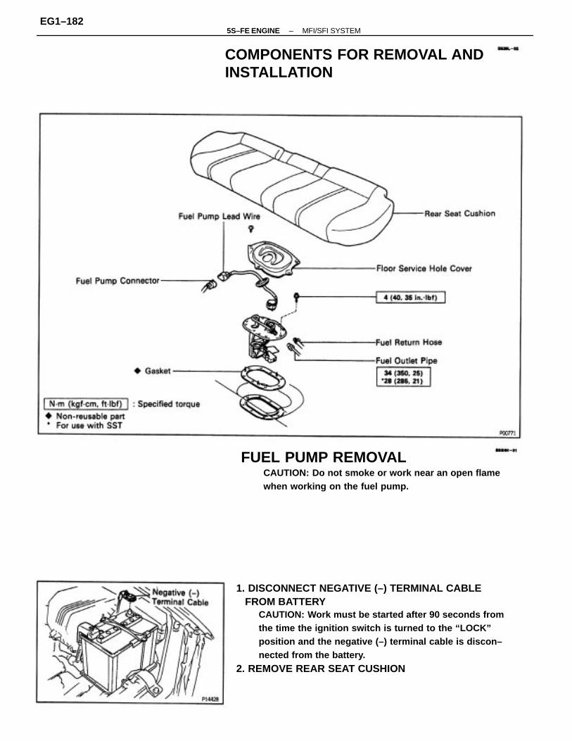
1. DISCONNECT NEGATIVE (–) TERMINAL CABLE FROM BATTERY
CAUTION: Work must be started after 90 seconds fromthe time the ignition switch is turned to the “LOCK”position and the negative (–) terminal cable is discon–nected from the battery.
2. REMOVE REAR SEAT CUSHION
FUEL PUMP REMOVALCAUTION: Do not smoke or work near an open flamewhen working on the fuel pump.
COMPONENTS FOR REMOVAL ANDINSTALLATION
–5S–FE ENGINE MFI/SFI SYSTEMEG1–182

5. DISCONNECT FUEL PIPE AND HOSE FROM FUEL PUMP BRACKET
CAUTION: Remove the fuel filter cap to prevent the fuelfrom flowing out.
(a) Using SST, disconnect the outlet pipe from the pump bracket.SST 09631–22020(b) Disconnect the return hose from the pump bracket.
3. REMOVE FLOOR SERVICE HOLE COVER(a) Disconnect the fuel pump connector.(b) Remove the 5 screws and service hole cover.4. REMOVE FUEL PUMP LEAD WIRE
6. REMOVE FUEL PUMP BRACKET ASSEMBLY FROM FUEL TANK
(a) Remove the 8 bolts.
(b) Pull out the pump bracket assembly.(c) Remove the gasket from the pump bracket.
–5S–FE ENGINE MFI/SFI SYSTEMEG1–183

FUEL PUMP DISASSEMBLY1. REMOVE FUEL PUMP FROM FUEL PUMP BRACKET
(a) Remove the fuel pump lead wire.(b) Pull off the lower side of the fuel pump from the pump
bracket.(c) Disconnect the fuel hose from the fuel pump, and
remove the fuel pump.(d) Remove the rubber cushion from the fuel pump.
2. REMOVE FUEL SENDER GAUGE FROM FUEL PUMP BRACKET
(a) Disconnect the fuel sender gauge connector.(b) Remove the 2 screws and sender gauge.
COMPONENTS FOR DISASSEMBLY ANDASSEMBLY
–5S–FE ENGINE MFI/SFI SYSTEMEG1–184

FUEL PUMP ASSEMBLY(See Components for Disassembly and Assembly)1. INSTALL CONNECTORInstall the gasket, connector and connector supportwith the 2 screws.2. INSTALL FUEL PUMP FILTER TO FUEL PUMPInstall the pump filter with a new clip.
4. INSTALL FUEL PUMP TO FUEL PUMP BRACKET(a) Install the rubber cushion to the fuel pump.(b) Connect the fuel hose to the outlet port of the fuel
pump.(c) Install the fuel pump by pushing the lower side of the
fuel pump.(d) Install the fuel pump connector.
3. INSTALL FUEL SENDER GAUGE TO FUEL PUMP BRACKET
(a) Install the sender gauge with the 2 screws.(b) Connect the fuel sender gauge connector.
4. REMOVE CONNECTORRemove the 2 screws, connector support, connectorand gasket.
3. REMOVE FUEL PUMP FILTER FROM FUEL PUMP(a) Using a small screwdriver, remove the clip.(b) Pull out the pump filter.
–5S–FE ENGINE MFI/SFI SYSTEMEG1–185

2. CONNECT FUEL PIPE AND HOSE TO FUEL PUMP BRACKET(a) Using SST, connect the outlet pipe to the pump
bracket.SST 09631–22020Torque: 28 N–m (285 kgf–cm, 21 ft–lbf)
(b) Connect the return hoses to the pump bracket.3. CHECK FOR FUEL LEAKAGE (See page EG1–176)4. CONNECT FUEL PUMP LEAD WIRE5. INSTALL FLOOR SERVICE HOLE COVER(a) Install the service hole cover with the 5 screws.(b) Connect the fuel pump (with fuel sender gauge)connector.
FUEL PUMP INSTALLATION(See Components for Removal and Installation)1. INSTALL FUEL PUMP BRACKET ASSEMBLY TO
FUEL TANK(a) Install a new gasket to the pump bracket.(b) Insert the pump bracket assembly into the fuel tank.
6. INSTALL REAR SEAT CUSHION7. CONNECT NEGATIVE (–) TERMINAL CABLE TOBATTERY
(c) Install the pump bracket with the 8 screws.Torque: 3.9 N–m (40 kgf–cm, 35 in.–Ibf)
–5S–FE ENGINE MFI/SFI SYSTEMEG1–186

2. DISCONNECT FUEL RETURN PIPE FROM FUEL PRESSURE REGULATOR
(a) Put a suitable container or shop rag under the pres–sure regulator.
(b) Remove the union bolt and 2 gaskets, and disconnectthe return pipe from the pressure regulator.HINT: Slowly loosen the union bolt.
FUEL PRESSURE REGULATORON–VEHICLE INSPECTIONINSPECT FUEL PRESSURE(See page EG1–178)
COMPONENTS FOR REMOVAL ANDINSTALLATION
FUEL PRESSURE REGULATOR REMOVAL1. DISCONNECT VACUUM SENSING HOSE FROM FUEL PRESSURE REGULATOR
–5S–FE ENGINE MFI/SFI SYSTEMEG1–187

FUEL PRESSURE REGULATORINSTALLATION(See Components for Removal and Installation)1. INSTALL FUEL PRESSURE REGULATOR
(a) Apply a light coat of gasoline to a new O–ring, andinstall it to the pressure regulator.
2. CONNECT FUEL RETURN PIPE TO FUEL PRESSURE REGULATOR Install the return pipe with 2 new gaskets and the union bolt.
Torque: 19 N–m (195 kgf–cm, 14 ft–lbf)
3. REMOVE FUEL PRESSURE REGULATOR(a) Remove the 2 bolts, and pull out the pressure regula–
tor.(b) Remove the O–ring from the pressure regulator.
3. CONNECT VACUUM SENSING HOSE TO FUEL PRESSURE REGULATOR4. CHECK FOR FUEL LEAKAGE (See page EG1–176)
(b) Install the pressure regulator with the 2 bolts.Torque: 5.4 N–m (55 kgf–cm, 48 in.–lbf)
–5S–FE ENGINE MFI/SFI SYSTEMEG1–188

2. INSPECT INJECTOR RESISTANCE(a) Disconnect the injector connector.(b) Using an ohmmeter, measure the resistance between the terminals.
Resistance: Approx. 13.8
If the resistance is not as specified, replace the injector.(c) Reconnect the injector connector.
ON–VEHICLE INSPECTION1. INSPECT INJECTOR OPERATIONCheck operation sound from each injector.(a) With the engine running or cranking, use a sound
scope to check that there is normal operating noise inproportion to engine speed.
(b) If you have no sound scope, you can check the injec–tor transmission operation with your finger.If no sound or unusual sound is heard, check thewiring connector, injector or injection signal from theECM.
INJECTOR
–5S–FE ENGINE MFI/SFI SYSTEMEG1–189

COMPONENTS FOR REMOVAL ANDINSTALLATION
–5S–FE ENGINE MFI/SFI SYSTEMEG1–190

5. REMOVE AIR CLEANER CAP, RESONATOR AND AIR CLEANER HOSE(a) Disconnect the intake air temperature sensor connector.(b) California only:Disconnect the air hose from the air cleaner hose.(c) Loosen the air cleaner hose clamp bolt.(d) Disconnect the 4 air cleaner cap clips.(e) Disconnect the air cleaner hose from the throttlebody, and remove the air cleaner cap together withthe resonator and air cleaner hose.
INJECTORS REMOVAL(See Components for Removal and Installation)1. DISCONNECT NEGATIVE (–) TERMINAL CABLE
FROM BATTERYCAUTION: Work must be started after 90 seconds fromthe time the ignition switch i: turned to the “LOCK”position and the negative (–) terminal cable is discon–nected from the battery.
2. DRAIN ENGINE COOLANT3. A/T:DISCONNECT THROTTLE CABLE FROMTHROTTLE BODY4. DISCONNECT ACCELERATOR CABLE FROMTHROTTLE BODY
6. REMOVE THROTTLE BODY(a) Disconnect throttle position sensor connector.(b) Disconnect IAC valve connector.
–5S–FE ENGINE MFI/SFI SYSTEMEG1–191

(f) Disconnect the following hoses from the throttlebody, and remove the throttle body.
(1) Water bypass hose from water outlet (2) Water bypass hose from water bypass pipe (3) California:
Air hose from cylinder headExcept California:Air hose from air tube
(c) Disconnect the following hoses from the throttlebody.
(1) PCV hose (2) 2 vacuum hoses from EGR vacuum modulator (3) Vacuum hose from TVV (for EVAP)
(d) Type A:Remove the 4 bolts.
(e) Type B:Remove the 2 bolts and 2 nuts.
8. DISCONNECT VACUUM HOSES FROM TVV (FOREVAP)
7. DISCONNECT PS VACUUM HOSES
–5S–FE ENGINE MFI/SFI SYSTEMEG1–192

10. DISCONNECT VACUUM HOSESDisconnect the following hoses:(1) MAP sensor hose from air intake chamber(2) Brake booster vacuum hose from air intake chamber(3) Vacuum sensing hose from fuel pressure regulator11. w/ A/C:
DISCONNECT A/C IDLE–UP VALVE CONNECTOR
12. DISCONNECT 2 ENGINE WIRE GROUND STRAPS FROM INTAKE MANIFOLD13. DISCONNECT KNOCK SENSOR AND VSV (FOR
EGR) CONNECTORS14. CALIFORNIA ONLY: DISCONNECT VSV (FOR FUEL PRESSURE CONTROL)
CONNECTOR AND VACUUM HOSES15. REMOVE BOLT AND WIRE CLAMP, AND DISCON– NECT ENGINE WIRE HARNESS
9. REMOVE EGR VALVE AND VACUUM MODULATOR(a) Disconnect the EGR gas temperature sensor connec-
tor.(b) Disconnect the following hoses: (1) 2 vacuum hoses from VSV (for EGR) (2) Vacuum hose from charcoal canister(c) Disconnect the vacuum hose clamp.
16. REMOVE INTAKE MANIFOLD(a) Remove the 4 bolts, wire bracket, No.1 air intake
chamber and manifold stays.
(d) Loosen the union nut of the EGR pipe, and remove the2 nuts, the EGR valve, vacuum modulator, vacuumhoses assembly and gasket.
–5S–FE ENGINE MFI/SFI SYSTEMEG1–193

(c) Remove the 2 bolts and delivery pipe together withthe 4 injectors.
NOTICE: Be careful not to drop the injectors when rem–oving the delivery pipe.
(d) Remove the 4 insulators (except California) and 2spacers from the cylinder head.
(e) Pull out the 4 injectors from the delivery pipe.
18. REMOVE DELIVERY PIPE AND INJECTORS(a) Loosen the pulsation damper, and disconnect the fuel
inlet pipe.(b) Disconnect the fuel return hose.
(c) Disconnect the 2 wire clamps from the wire bracketson the intake manifold.
(b) Remove the 6 bolts, 2 nuts, intake manifold andgasket.
17. DISCONNECT INJECTOR CONNECTORS
–5S–FE ENGINE MFI/SFI SYSTEMEG1–194

(c) Install a new O–ring to the fuel inlet of pressure regulator.(d) Connect SST (hose) to the fuel inlet of the pressure
regulator with SST (union) and the 2 bolts.SST 09268–41045 (09268–41090)Torque: 5.4 N–m (55 kgf–cm, 48 ft–lbf)
(e) Connect the fuel return hose to the fuel outlet of thepressure regulator with SST (union), 2 new gaskets
and union bolts.
(a) Disconnect the fuel hose from the fuel filter outlet.(b) Connect SST (union and hose) to the fuel filter outlet
with 2 new gaskets and union bolts.SST 09268–41045 (90405–09015)Torque: 29 N–m (300 kgf–cm, 22 ft–lbf)
HINT: Use the vehicle’s fuel filter.
INJECTORS INSPECTION1. INSPECT INJECTOR INJECTION
CAUTION: Keep injector clear of sparks during the test.
(f) California:Remove the 2 O–rings, insulator and grommet fromeach injector.
(g) Except California:Remove the O–ring and grommet from each injector.
–5S–FE ENGINE MFI/SFI SYSTEMEG1–195

(l) Connect SST (wire) to the injector and battery for 15seconds, and measure the injection volume with agraduated cylinder. Test each injector 2 or 3 times.SST 09842–30070Volume:49 – 59 cm (3.0–3.6 cu in.) per 15 sec.Difference between each Injector:5 cm (0.3 cu in.) or lessIf the injection volume is not as specified, replace theinjector.
2. INSPECT LEAKAGE(a) In the condition above, disconnect the test probes of
SST (wire) from the battery and check the fuel leakagefrom the injector.SST 09842–30070Fuel drop:One drop or less per minute
(b) Disconnect the negative (–) terminal cable from thebattery.
SST 09268–41045 (09268–41080)Torque: 18 N–m (180 kgf–cm, 13 ft–lbf)
(f) Install the grommet and a new O–ring to the injector.(g) Connect SST (union and hose) to the injector, and hold
the injector and union with SST (clamp).SST 09268–41045
(h) Put the injector into a graduated cylinder.HINT: Install a suitable vinyl hose onto the injector toprevent gasoline from splashing out.
(i) Using SST, connect terminals +B and FP of the datalink connector 1.SST 09843–18020
(j) Reconnect the negative (–) terminal cable to thebattery.
(k) Turn the ignition switch ON.NOTICE: Do not start the engine.
(c) Remove the SST. SST 09268–41045 and 09843–18020
–5S–FE ENGINE MFI/SFI SYSTEMEG1–196
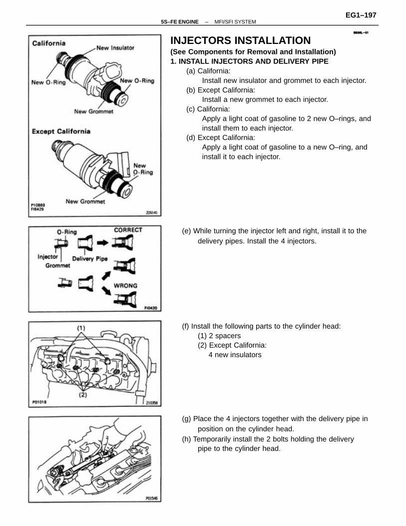
INJECTORS INSTALLATION(See Components for Removal and Installation)1. INSTALL INJECTORS AND DELIVERY PIPE
(a) California:Install new insulator and grommet to each injector.
(b) Except California:Install a new grommet to each injector.
(c) California:Apply a light coat of gasoline to 2 new O–rings, andinstall them to each injector.
(d) Except California:Apply a light coat of gasoline to a new O–ring, andinstall it to each injector.
(g) Place the 4 injectors together with the delivery pipe inposition on the cylinder head.
(h) Temporarily install the 2 bolts holding the deliverypipe to the cylinder head.
(f) Install the following parts to the cylinder head:(1) 2 spacers(2) Except California: 4 new insulators
(e) While turning the injector left and right, install it to thedelivery pipes. Install the 4 injectors.
–5S–FE ENGINE MFI/SFI SYSTEMEG1–197

(i) Check that the injectors rotate smoothly.HINT: If injectors do not rotate smoothly, the probablecause is incorrect installation of O – rings. Replace theO–rings.
(j) Position the injector connector upward.
(l) Connect the fuel return hose.(m) Connect the fuel inlet pipe to the delivery pipe with 2
new gaskets and the pulsation damper.Torque: 34 N–m (350 kgf–cm, 25 ft–lbf)
(k) Tighten the 2 bolts holding the delivery pipe to thecylinder head.
Torque: 13 N–m (130 kgf–cm, 9 ft–lbf)
3. INSTALL INTAKE MANIFOLD(a) Connect the 2 wire clamps to the wire brackets
on the intake manifold.
2. CONNECT INJECTOR CONNECTORS
–5S–FE ENGINE MFI/SFI SYSTEMEG1–198

4. CONNECT ENGINE WIRE HARNESS WITH WIRECLAMP AND BOLT
5. CALIFORNIA ONLY:CONNECT VSV (FOR FUEL PRESSURE CONTROL)CONNECTOR AND VACUUM HOSES
6. CONNECT KNOCK SENSOR AND VSV (FOR EGR) CONNECTORS7. CONNECT 2 ENGINE WIRE GROUND STRAPS TO INTAKE MANIFOLD
10. INSTALL EGR VALVE AND VACUUM MODULATOR(a) Install a new gasket and the EGR valve with the union
nut and 2 nuts. Union nut
Torque: 59 N–m (600 kgf–cm. 43 ft–lbf)NutTorque: 13 N–m (130 kgf–cm. 9 ft–lbf)
(b) Install the EGR vacuum modulator to the clamp.
8. CONNECT VACUUM HOSESConnect the following hoses:(1) MAP sensor hose to air intake chamber
(2) Brake booster vacuum hose to air intake chamber(3) Vacuum sensing hose to fuel pressure regulator.
9. w/ A/C:CONNECT A/C IDLE–UP VALVE CONNECTOR
(c) Install the No. 1 air intake chamber and manifold stays,wire bracket with the 4 bolts.14 mm head boltTorque: 42 N–m (425 kgf–cm, 31 ft–lbf)12 mm head boltTorque: 22 N–m (220 kgf–cm, 16 ft–lbf)
(b) Install a new gasket and the intake manifold with the 6 bolts and 2 nuts. Uniformly tighten the bolts and nuts in several passes.
Torque: 19 N–m (195 kgf–cm, 14 ft–lbf)
–5S–FE ENGINE MFI/SFI SYSTEMEG1–199

(c) Connect the vacuum hose clamp.(d) Connect the following hoses:
(1) Vacuum hose to charcoal canister(2) Vacuum hose (from EGR valves) to E port of VSV
(for EGR)(3) Vacuum hose (from Q port EGR vacuum modula–
tor) to G port of VSV (for EGR)(e) Connect the EGR gas temperature sensor connector.
13. INSTALL THROTTLE BODY(a) Connect the following hoses to the throttle body: (1) Water bypass hose from water outlet (2) Water bypass hose from water bypass pipe (3) California:
Air hose from cylinder head Except California: Air hose to air tube
11. CONNECT VACUUM HOSES TO VSV (FOR EVAP)(a) From P port of throttle body(b) From charcoal canister
(b) Place a new gasket on the intake chamber, facing theprotrusion downward.
12. CONNECT PS VACUUM HOSES
–5S–FE ENGINE MFI/SFI SYSTEMEG1–200

(c) Type A:Install the throttle body with the 4 bolts.
Torque: 19 N–m (195 kgf–cm, 14 ft–lbf)Bolt length:
A 45 mm (1.77 in.) B 55 mm (2.17 in.)
(d) Type B:Install the throttle body with the 2 bolts and 2 nuts.
Torque: 19 N–m (195 kgf–cm, 14 ft–lbf)
14. INSTALL AIR CLEANER CAP, RESONATOR AND AIR CLEANER HOSE
(a) Connect the air cleaner hose to the throttle body.(b) Install the air cleaner cap together with the resonator
and air cleaner hose.(c) California only:
Connect the air hose to the air cleaner hose.(d) Connect the intake air temperature sensor connector.
15. A/T:CONNECT AND ADJUST THROTTLE CABLE16. CONNECT AND ADJUST ACCELERATOR CABLE17. FILL WITH ENGINE COOLANT Capacity: 6.3 liters (6.7 US qts. 5.5 Imp. qts)18. CONNECT NEGATIVE (–) TERMINAL CABLE TO BATTERY
(e) Connect the following hoses to the throttle body:(1) PCV hose(2) 2 vacuum hoses from EGR vacuum modulator(3) Vacuum hose from TVV (for EVAP)
(f) Connect the IAC valve connector.(g) Connect the throttle position sensor connector.
–5S–FE ENGINE MFI/SFI SYSTEMEG1–201

FUEL TANK AND LINECOMPONENTS
–5S–FE ENGINE MFI/SFI SYSTEMEG1–202

FUEL LINES AND CONNECTIONSINSPECTION(a) Check the fuel lines for cracks, leakage and all con–
nections for deformation.(b) Check the fuel tank vapor vent system hoses and
connections for looseness, sharp bends or damage.(c) Check the fuel tank for deformation, cracks, fuel leak–
age and tank band looseness.(d) Check the filler neck for damage or fuel leakage.(e) Hose and tube connections are as shown in the illus–
tration.If a problem is found, repair or replace the part asnecessary.
PRECAUTIONS1. Always use new gaskets when replacing the fuel
tank or component parts.2. Apply the proper torque to all parts tightened.
–5S–FE ENGINE MFI/SFI SYSTEMEG1–203

2. INSPECT THROTTLE POSITION SENSOR(a) Apply vacuum to the throttle opener.(b) Disconnect the sensor connector.(c) Insert a thickness gauge between the throttle stop
screw and stop lever.
ON–VEHICLE INPSECTION1. INSPECT THROTTLE BODY(a) Check that the throttle linkage moves smoothly.
(b) Check the vacuum at each port.• Start the engine.• Check the vacuum with your finger.
THROTTLE BODY
Other than idle
No vacuum No vacuum
No vacuum
No vacuum
Port name
Vacuum
Vacuum
At idle
–5S–FE ENGINE MFI/SFI SYSTEMEG1–204

3. INSPECT AND ADJUST THROTTLE OPENERA. Warm up engineAllow the engine to warm up to normal operatingtemperature.B. Check idle speed
Idle speed: 750 ± 50 rpm
C. Check and adjust throttle opener setting speed(a) Disconnect the vacuum hose from the throttle opener,
and plug the hose end.(b) Maintain the engine at 2,500 rpm.
(c) Release the throttle valve.(d) Check that the throttle opener is set.
Throttle opener setting speed:1,300 – 1,500 rpm (w/ Cooling fan OFF)
(d) Using an ohmmeter, measure the resistance betweeneach terminal.
(e) Reconnect the sensor connector.
Clearance betweenlever and stop screw
Throttle valve fully open
0.50 mm (0.020 in.)
0.70 mm (0.028 in.)
Betweenterminals
2.0 – 10.2 k
2.3 k or less
0.2 – 5.7 k0 mm (0 in.)
2.5 – 5.9 k
Resistance
VTA – E2
IDL – E2
VTA – E2
IDL – E2
VC – E2
Infinity
–5S–FE ENGINE MFI/SFI SYSTEMEG1–205

(e) Adjust the throttle opener setting speed by turningthe throttle opener adjusting screw.
COMPONENTS FOR REMOVAL ANDINSTALLATION
(f) Reconnect the vacuum hose to the throttle opener.
–5S–FE ENGINE MFI/SFI SYSTEMEG1–206

5. REMOVE AIR CLEANER CAP, RESONATOR AND AIR CLEANER HOSE(a) Disconnect the intake air temperature sensor connec–
tor.(b) California only:
Disconnect the air hose from the air cleaner hose.(c) Loosen the air cleaner hose clamp bolt.(d) Disconnect the 4 air cleaner cap clips.(e) Disconnect the air cleaner hose from the throttle
body, and remove the air cleaner cap together withthe resonator and air cleaner hose.
1. DISCONNECT NEGATIVE (–) TERMINAL CABLE FROM BATTERY
CAUTION: Work must be started after 90 seconds fromthe time the ignition switch is turned to the “LOCK”position and the negative (–) terminal cable is discon–nected from the battery.
2. DRAIN ENGINE COOLANT3. DISCONNECT ACCELERATOR CABLE FROM THROTTLE LINKAGE4. A/T:
DISCONNECT THROTTLE CABLE FROM THROTTLE LINKAGE
6. REMOVE THROTTLE BODY(a) Disconnect the throttle position sensor connector.(b) Disconnect the IAC valve connector.
THROTTLE BODY REMOVAL
–5S–FE ENGINE MFI/SFI SYSTEMEG1–207

THROTTLE BODY INSPECTION1. CLEAN THROTTLE BODY
(a) Using a soft brush and carburetor cleaner, clean thecast parts.
(b) Using compressed air, clean all the passengers andapertures.
NOTICE: To prevent deterioration, do not clean thethrottle position sensor.
(f) Disconnect the following hoses from the throttlebody, and remove the throttle body.
(1) Water bypass hose from water outlet (2) Water bypass hose from water bypass pipe (3) California:
Air hose from cylinder headExcept California:Air hose from air tube
(c) Disconnect the following hoses from the throttlebody.
(1) PCV hose (2) 2 vacuum hoses from EGR vacuum modulator (3) Vacuum hose from TVV (for EVAP)
7. IF NECESSARY, REMOVE IAC VALVE FROM THROTTLE BODYRemove the 4 screws, IAC valve and gasket.
(d) Type A: Remove the 4 bolts.
(e) Type B:Remove the 2 bolts and 2 nuts.
–5S–FE ENGINE MFI/SFI SYSTEMEG1–208

(b) Apply vacuum to the throttle opener.(c) Insert a 0.60 mm (0.024 in.) thickness gauge between
the throttle stop screw and stop lever.(d) Connect the test probe of an ohmmeter to the termi–
nals IDL and E2 of the sensor.(e) Gradually turn the sensor clockwise until the ohmmeter
deflects, and secure it with the 2 set screws.
3. INSPECT THROTTLE POSITION SENSOR(a) Apply vacuum to the throttle opener.(b) Insert a thickness gauge between the throttle stop
screw and stop lever.(c) Using an ohmmeter, measure the resistance between
each terminal.
2. INSPECT THROTTLE VALVE(a) Apply vacuum to the throttle opener.(b) Check that there is no clearance between the throttlestop screw and throttle lever when the throttle valveis fully closed.
4. IF NECESSARY, ADJUST THROTTLE POSITION SENSOR(a) Loosen the 2 set screws of the sensor.
Clearance betweenlever and stop screw
Throttle valve fullyopen
0.50 mm (0.020 in.)
0.70 mm (0.028 in.)
Between terminals
2.0 – 10.2 k
2.3 k or less
0.2 – 5.7 k0 mm (0 in.)
2.5 – 5.9 k
Resistance
VTA – E2
VTA – E2
IDL–E2
IDL–E2
Infinity
VC – E2
–5S–FE ENGINE MFI/SFI SYSTEMEG1–209

2. INSTALL THROTTLE BODY(a) Connect the following hoses to the throttle body:
(1) Water bypass hose from water outlet(2) Water bypass hose from water bypass pipe(3) California:
Air hose from cylinder headExcept California:Air hose from air tube
THROTTLE BODY INSTALLATION(See Components for Removal and Installation)1. INSTALL IAC VALVE TO THROTTLE BODY(a) Place a new gasket on the throttle body.
(b) Place a new gasket on the intake chamber, facing theprotrusion downward.
(f) Recheck the continuity between terminals IDL and E2.
(b) install the IAC valve with the 4 screws.
Clearance betweenlever and stop screw Continuity (IDL – E2)
0.50 mm (0.020 in.)
0.70 mm (0.028 in.) No continuity
Continuity
–5S–FE ENGINE MFI/SFI SYSTEMEG1–210

(c) Type A:Install the throttle body with the 4 bolts.
Torque: 19 N–m (195 kgf–cm, 14 ft–lbf)
Bolt length: A 45 mm (1.77 in.) B 55 mm (2.17 in.)(d) Type B:
Install the throttle body with the 2 bolts and 2 nuts.Torque: 19 N–m (195 kgf–cm, 14 ft–lbf)
3. INSTALL AIR CLEANER CAP, RESONATOR AND AIR CLEANER HOSE
(a) Connect the air cleaner hose to the throttle body.(b) Install the air cleaner cap together with the resonator
and air cleaner hose.(c) California only:
Connect the air hose to the air cleaner hose.(d) Connect the intake air temperature sensor connector.
4. A/T:CONNECT AND ADJUST THROTTLE CABLE5. CONNECT AND ADJUST ACCELERATOR CABLE6. FILL WITH ENGINE COOLANT7. CONNECT NEGATIVE (–) TERMINAL CABLE TOBATTERY
(e) Connect the following hoses to the throttle body: (1) PCV hose (2) 2 vacuum hoses from EGR vacuum modulator (3) Vacuum hose from TVV (for EVAP)
(f) Connect the IAC valve connector.(g) Connect the throttle position sensor connector.
–5S–FE ENGINE MFI/SFI SYSTEMEG1–211

(b) Using SST, connect terminals TE1 and E1 of the datalink connector 1.SST 09843–18020
(c) Maintain engine speed in the range between 900 –1,300 rpm for 5 seconds. Check that it returns to idlespeed.If the engine speed operation is not as specified,check the IAC valve, wiring and ECM.
ON–VEHICLE INSPECTION1. INSPECT IAC VALVE OPERATION
(a) Initial conditions:
• Engine at normal operating temperature
• Idle speed set correctly
• Transmission in neutral position
IDLE AIR CONTROL (IAC) VALVE
(d) Remove the SST.SST 09843–18020
–5S–FE ENGINE MFI/SFI SYSTEMEG1–212

2. INSPECT IAC VALVE RESISTANCE(a) Disconnect the IAC valve connector.(b) Using an ohmmeter, measure the resistance between
terminal + B and other terminals (ISCC, ISCO).Resistance: 19.3–22–3Ω
If resistance is not as specified, replace the IAC valve.(c) Reconnect the IAC valve connector.
COMPONENTS FOR REMOVAL ANDINSTALLATION
–5S–FE ENGINE MFI/SFI SYSTEMEG1–213

IAC VALVE INSPECTIONINSPECT IAC VALVE OPERATION
(a) Connect the positive (+) lead from the battery toterminal +B and negative (–) lead to terminal ISCC,and check that the valve is closed.
IAC VALVE REMOVAL(See Components for Removal and Installation)1. REMOVE THROTTLE BODY(See steps 1 to 6 on pages EG1–207 and 208)
IAC VALVE INSTALLATION(See Components for Removal and Installation)1. INSTALL IAC VALVE
(a) Place a new gasket on the throttle body.
(b) Connect the positive (+) lead from the battery toterminal +B and negative (–) lead to terminal ISCO,and check that the valve is open.
2. REMOVE IAC VALVERemove the 4 screws, IAC valve and gasket.
–5S–FE ENGINE MFI/SFI SYSTEMEG1–214

2. INSTALL THROTTLE BODY(See steps 2 to 7 on pages EG1–210 and 211)
(b) Install the IAC valve with the 4 screws.
–5S–FE ENGINE FE ENGINE – MFI/SFI SYSTEMEG1–215

2. INSPECT EFI MAIN RELAYA. Inspect relay continuity
(a) Using an ohmmeter, check that there is continuitybetween terminals 1 and 2.
(b) Check that there is no continuity between terminals 3and 5.If continuity is not as specified, replace the relay.
B. Inspect relay operation(a) Apply battery voltage across terminals 1 and 2.(b) Using an ohmmeter, check that there is continuity
between terminals 3 and 5.If operation is not as specified, replace the relay.
3. REINSTALL EFI MAIN RELAY
EFI MAIN RELAY INSPECTION7. REMOVE EFI MAIN RELAY
EFI MAIN RELAY
–5S–FE ENGINE FE ENGINE – MFI/SFI SYSTEMEG1–216

CIRCUIT OPENING RELAY REMOVAL ANDINSTALLATION
CIRCUIT OPENING RELAY
–5S–FE ENGINE MFI/SFI SYSTEMEG1–217

CIRCUIT OPENING RELAY INSPECTION1. INSPECT RELAY CONTINUITY(a) Using an ohmmeter, check that there is continuity
between terminals ST and E1.(b) Check that there is continuity between terminals +B
and FC.(c) Check that there is no continuity between terminals +
B and FP.If continuity is not as specified, replace the relay.2. INSPECT RELAY OPERATION(a) Apply battery voltage across terminals ST and E1.(b) Using an ohmmeter, check that there is continuity
between terminals +B and FP.If operation is not as specified, replace the relay.
–5S–FE ENGINE MFI/SFI SYSTEMEG1–218

3. INSPECT ECT SENSOR RESISTANCEUsing an ohmmeter, measure the resistance betweenthe terminals.Resistance: Refer to the graph aboveIf the resistance is not as specified, replace thesensor.4. REINSTALL ECT SENSOR5. FILL WITH ENGINE COOLANT
ENGINE COOLANT TEMPERATURE(ECT) SENSOR
ECT SENSOR INSPECTION1. DRAIN ENGINE COOLANT2. REMOVE ECT SENSOR
–5S–FE ENGINE MFI/SFI SYSTEMEG1–219

2. INSPECT IAT SENSOR RESISTANCEUsing an ohmmeter, measure the resistance betweenthe terminals.Resistance: Refer to the graph aboveIf the resistance is not as specified, replace thesensor.3. REINSTALL IAT SENSOR
INTAKE AIR TEMPERATURE (IAT)SENSOR
IAT SENSOR INSPECTION1. REMOVE IAT SENSOR
–5S–FE ENGINE MFI/SFI SYSTEMEG1–220

MAP SENSOR INSPECTION1. INSPECT POWER SOURCE VOLTAGE OF MAP
SENSOR(a) Disconnect the MAP sensor connector.(b) Turn the ignition switch ON.(c) Using a voltmeter measure the voltage between con–
nector terminals VC and E2 of the wiring harness side.Voltage: 4.75 – 5.25 V
(d) Reconnect the MAP sensor connector.
MANIFOLD ABSOLUTE PRESSURE(MAP) SENSOR
–5S–FE ENGINE MFI/SFI SYSTEMEG1–221

2. INSPECT POWER OUTPUT OF MAP SENSOR(a) Turn the ignition switch ON.(b) Disconnect the vacuum hose on the air intake cham–
ber side.(c) Connect a voltmeter to terminals PIM and E2 of the
ECM, and measure the output voltage under ambientatmospheric pressure.
(d) Apply vacuum to the MAP sensor in 13.3 kPa (100mmHg, 3.94 in.Hg) segments to 66.7 kPa (500 mmHg,19.69 in.Hg).
(e) Measure the voltage drop from step(c) above for each
segment.Voltage drop:
AppliedVacuumkPa(mmHg in.Hg)
66.7( 500 19.69)
53.5( 400 15.75)
40.0( 300111.8)
13.3(1003.94 )
26.7(2007.87)
Voltagedrop V 0.7–0.90.3–0.5 1.1 –1.3 1.5 – 1.7 1.9 – 2.1
–5S–FE ENGINE MFI/SFI SYSTEMEG1–222

VSV INSPECTION (California)1. REMOVE VSV(a) Disconnect the following connectors and hoses:
(1) VSV for EGR (A) connector(2) VSV for fuel pressure control (B) connector(3) Vacuum hose (from EGR valve) from port E of
VSV (A)(4) Vacuum hose (from port “Q” of EGR vacuum
modulator) from port G of VSV (A)(5) Vacuum hose (from fuel pressure regulator) from
port E of VSV (B)(6) Vacuum hose (from air intake chamber) from port
G of VSV (B)(b) Remove the bolt and VSV assembly.
2. INSPECT VSVA. Inspect VSV for open circuit
Using an ohmmeter, check that there is continuitybetween the terminals.Resistance (Cold):33–39
If there is no continuity, replace the VSV.
VSV FOR EGR
–5S–FE ENGINE MFI/SFI SYSTEMEG1–223

VSV INSPECTION (Except California)1. REMOVE VSV(a) Disconnect the following connector and hoses: (1) VSV connector (2) Vacuum hose (from EGR valve) from port E of
VSV (3) Vacuum hose (from port “a” of EGR vacuum
modulator) from port G of VSV(b) Remove the bolt and VSV.2. INSPECT VSVA. Inspect VSV for open circuitUsing an ohmmeter, check that there is continuitybetween the terminals.Resistance (Cold):33–39If there is no continuity, replace the VSV.
B. Inspect VSV for groundUsing an ohmmeter, check that there is no continuitybetween each terminal and the body.If there is continuity, replace the VSV.
(b) Apply battery voltage across the terminals.(c) Check that air flows from port E to the filter.
If operation is not as specified, replace the VSV.3. REINSTALL VSV
C. Inspect VSV operation(a) Check that air flows from port E to port G.
–5S–FE ENGINE MFI/SFI SYSTEMEG1–224

B. Inspect VSV for groundUsing an ohmmeter, check that there is no continuitybetween each terminal and the body.If there is continuity,. replace the VSV.
(b) Apply battery voltage across the terminals.(c) Check that air flows from port E to the filter.
If operation is not as specified, replace the VSV.3. REINSTALL VSV
C. Inspect VSV operation(a) Check that air flows from port E to port G.
–5S–FE ENGINE MFI/SFI SYSTEMEG1–225

VSV INSPECTION1. REMOVE VSV(a) Disconnect the following connectors and hoses: (1) VSV for EGR (A) connector (2) VSV for fuel pressure control (B) connector (3) Vacuum hose (from EGR valve) from port E of VSV (A) (4) Vacuum hose (from port “a” of EGR vacuum
modulator) from port G of VSV (A) (5) Vacuum hose (from fuel pressure regulator) from
port E of VSV (B) (6) Vacuum hose (from air intake chamber) from port
G of VSV (B)(b) Remove the bolt and VSV assembly.
2. INSPECT VSVA. Inspect VSV for open circuit
Using an ohmmeter, check that there is continuitybetween the terminals.Resistance (Cold):33–39
If there is no continuity, replace the VSV.
VSV FOR FUEL PRESSURE CONTROL(California only)
–5S–FE ENGINE MFI/SFI SYSTEMEG1–226

B. Inspect VSV for groundUsing an ohmmeter, check that there is no continuitybetween each terminal and the body.If there is continuity, replace the VSV.
(b) Apply battery voltage across the terminals.(c) Check that air flows from pipe E to the filter.
If operation is not as specified, replace the VSV.
C. Inspect VSV operation(a) Check that air flows from pipe E to pipe G.
3. REINSTALL VSV
–5S–FE ENGINE MFI/SFI SYSTEMEG1–227

A/C IDLE– UP VALVE INSPECTION1. REMOVE IDLE–UP VALVE
(a) Disconnect the following connector and hoses:(1) Idle–up valve connector(2) Air hose from air intake chamber(3) Air hose from air tube(b) Remove the 2 bolts and idle–up valve together with
the 2 air hoses.(c) Disconnect the 2 air hoses from the idle–up valve.
2. INSPECT IDLE–UP VALVEA. Inspect idle–up valve for open circuitUsing an ohmmeter, check that there is continuitybetween the terminals.Resistance (Cold): 30–34If there is no continuity, replace the idle–up valve.
B. Inspect idle–up valve for groundUsing an ohmmeter, check that there is no continuitybetween each terminal and the body.If there is continuity, replace the idle–up valve.
A–C IDLE–UP VALVE
–5S–FE ENGINE MFI/SFI SYSTEMEG1–228

(b) Apply battery voltage across the terminals.(c) Check that air flows from port E to port F.
If operation is not as specified, replace the idle–upvalve.
C. Inspect idle–up valve operation(a) Check that air does not flow from port E to port F.
3. REINSTALL IDLE– UP VALVE
–5S–FE ENGINE MFI/SFI SYSTEMEG1–229

2. INSPECT EGR GAS TEMPERATURE SENSORUsing an ohmmeter, measure the resistance betweenthe terminals.Resistance:64–97 k at 50C (122F)11–16 k at 100C (212F)2–4 k at 150C (302F)If the resistance is not as specified, replace thesensor.
EGR GAS TEMPERATURE SENSORINSPECTION1. REMOVE EGR GAS TEMPERATURE SENSOR
EGR GAS TEMPERATURE SENSOR
3. REINSTALL EGR GAS TEMPERATURE SENSOR
–5S–FE ENGINE MFI/SFI SYSTEMEG1–230

OXYGEN SENSOROXYGEN SENSOR INSPECTION1. WARM UP ENGINEAllow the engine to warm up to normal operatingtemperature.2. INSPECT FEEDBACK VOLTAGEConnect the positive (+) probe of a voltmeter toterminal VF1 of the data link connector 1 and nega–tive (–) probe to terminal E1. Perform the test asfollows:
Using SST, connect terminals TE1 and E1 of the data linkconnector 1.SST 09843–18020And maintain engine speed at 2,500 rpm.
Warm up the oxygen sensor with the engine at 2,500 rpmfor approx. 90 seconds. And maintain engine speed at2,500 rpm.
Warm up the oxygen sensor with the engine at 2,500 rpmfor approx. 90 seconds.
CONTINUED ON PAGE EG1–232
Disconnect terminals TE1 and E1 of the data linkconnector 1. And maintain engine speed at 2,500 rpm.
Check the number of times the voltmeter needle fluctuatesin 10 seconds.
Zero again After replacing 1 the oxygen sensor
Check the number of times the voltmeter needle fluctuates in 10 seconds.
Read and record diagnostic trouble codes. (See page EG1–297)
Malfunction code(s)(Ex. code Nos. 21, 25 and 26)
Measure voltage between terminals VF1 and E1.
Repair the relevant diagnostic trouble code.
Normal code, codeNos. 21, 25 and 26
Replace the ECM.
Less than 8 times
Less than 8 times
8 times or more
More than 0 V
8 timesor more
Normal
Zero
Zero
–5S–FE ENGINE MFI/SFI SYSTEMEG1–231

Disconnect the engine coolant temp. sensor connector andconnect resistor with a resistance of 4 – 8 k or send anequivalent simulation signal.
Warm up the oxygen sensor with the engine at 2,500 rpm forapprox. 90 seconds. And maintain engine at 2,500 rpm.
Disconnect terminals TE1 and E1 of the data link connector 1.And maintain engine at 2,500 rpm.
CONTINUED FROM PAGE EG1–231
Read and record diagnostic trouble codes. (See pageEG1–297)
Connect terminals TE1 and E1 of the data link connector 1.
Malfunction code(s)(Ex. code Nos. 21, 25 and 26)
Measure voltage between terminals VF1 and E1.
Measure voltage between terminals VF1 and E1,
Measure voltage between terminals VF1 and E1.
Repair the relevant diagnostic trouble code.
Normal code, code Nos.21, 25 and 26
Replace the oxygen sensor.
Disconnect the PCV hose.
Repair (Over Lean)
Repair (Over rich)
More than 0 V
–5S–FE ENGINE MFI/SFI SYSTEMEG1–232

SUB OXYGEN SENSORSUB OXYGEN SENSOR INSPECTIONINSPECT SUB OXYGEN SENSORHINT: Inspect only when code No. 27 is displayed.(a) Cancel the diagnostic trouble code. (See page EG1–299)(b) Warm up the engine until it reaches normal operating
temperature.(c) M/T:
Drive for 5 minutes or more at a speed less than 80km/h (50 mph) in 4th or 5th gear.A/T:Drive for 5 minutes or more at a speed less than 80km/h (50 mph) in “D” position.
(d) Following the conditions in step (c), fully depress onthe accelerator pedal for 2 seconds or more.
(e) Stop the vehicle and turn the ignition switch OFF.(f) Carry out steps (b), (c) and (d) again to test accelera–
tion. If code No.27 appears again, check the sub oxygensensor circuit. If the circuit is normal, replace the suboxygen sensor.
–5S–FE ENGINE MFI/SFI SYSTEMEG1–233

ENGINE CONTROL MODULE (ECM)ECM REMOVAL AND INSTALLATION
ECM INSPECTION(See page EG1–318)
–5S–FE ENGINE MFI/SFI SYSTEMEG1–234

2. CONNECT TACHOMETER TO ENGINEConnect the test probe of a tachometer to terminal IG(–) of the data link connector 1.
NOTICE:
• NEVER allow the tachometer terminal to touchground as it could result in damage to the igniterand/or ignition coil.
• As some tachometers are not compatible with thisignition system, we recommend that you confirmthe compatibility of yours before use.
3. INSPECT FUEL CUT RPM(a) Increase the engine speed to at least 2,500 rpm.(b) Use a sound scope to check for injector operating
noise.(c) Check that when the throttle lever is released, injector
operation noise stops momentarily and then resumes.HINT: Measure with the A/C OFF.Fuel return speed: 1,500 rpm4. DISCONNECT TACHOMETER
FUEL CUT RPMFUEL CUT RPM INSPECTION1. WARM UP ENGINEAllow the engine to warm up to normal operatingtemperature.
–5S–FE ENGINE MFI/SFI SYSTEMEG1–235

Clearance between stop screw and lever
0 mm (0 in.)
0.50 mm (0.020 in.)
0.70 mm (0.028 in.)
Throttle valve fully open
SERVICE SPECIFICATIONSSERVICE DATA
Resistance
Injection volume
Difference between each cylinder
Fuel leakage
Throttle body fully closed angleThrottle opener setting speed
VSV for Fuelpressure(Californiaonly)
EG R gas
temperature
sensor
Resistance (+B – ISCC or ISCO)
Throttle
position
sensor
Fuel pressureregulator
A/C idle –upvalve
Power source voltage
Fuel return rpm
Fuel pressure
Throttle body
Fuel cut rpm
VSV for EG R
at no vacuum
MAP sensor
Fuel pump
IAT sensor
ECT sensor
Resistance
Resistance
Resistance
Resistance
Resistance
Resistance
Resistance
IAC valve
Injector
–5S–FE ENGINE MFI/SFI SYSTEMEG1–236

TORQUE SPECIFICATIONS
No.1 air intake chamber stay x Intake manifold
No.1 air intake chamber stay x Cylinder head
Fuel return pipe x Fuel pressure regulator
Fuel pressure regulator x Delivery pipe
Fuel pulsation damper x Delivery pipe
Intake manifold stay x Intake manifold
Intake manifold stay x Cylinder block
Fuel line (Flare nut type – use SST)
Throttle body x Intake manifold
Intake manifold x Cylinder head
Delivery pipe x Cylinder head
EGR pipe x Intake manifold
Fuel pump side Others
Fuel line (Union bolt type)
Fuel pump x Fuel tank
Fuel tank band x Body
EGR pipe union nut
Part tightened
–5S–FE ENGINE MFI/SFI SYSTEMEG1–237

The cooling system is composed of the water jacket (inside the cylinder block and cylinder head),radiator, water pump, thermostat, electric fan, hoses and other components.Engine coolant which is heated in the water jacket is pumped to the radiator, through which anelectric fan blows air to cool the coolant as it passes through. Engine coolant which has beencooled is then sent back to the engine by the water pump, where it cools the engine.The water jacket is a network of channels in the shell of the cylinder block and cylinder headthrough which coolant passes. It is designed to provide adequate cooling of the cylinders andcombustion chambers which become heated during engine operation.
DESCRIPTIONThis engine utilizes a pressurized forced circulation cooling system which includes a thermostatequipped with a bypass valve mounted on the inlet side.
OPERATION
COOLING SYSTEM
–5S–FE ENGINE COOLING SYSTEMEG1–238

RADIATORThe radiator performs the function of cooling the coolant which has passed through the waterjacket and become hot, and it is mounted in the front of the vehicle. The radiator consists of anupper tank and lower tank, and a core which connects the two tanks. The upper tank contains theinlet for coolant from the water jacket and the filler inlet. It also has a hose attached throughwhich excess coolant or steam can flow. The lower tank has an outlet and drain cock for thecoolant. The core contains many tubes through which coolant flows from the upper tank to thelower tank as well as to cooling fins which radiate heat away from the coolant in the tubes. Theair sucked through the radiator by the electric fan, as well as the wind generated by the vehicle’stravel, passes through the radiator, cooling the coolant. Models with automatic transmissioninclude an automatic transmission fluid cooler built into the lower tank of the radiator. A fan withan electric motor is mounted behind the radiator to assist the flow of air through the radiator. Thefan operates when the engine coolant temperature becomes high in order to prevent it from be-coming too high.RADIATOR CAPThe radiator cap is a pressure type cap which seals the radiator, resulting in pressurization of theradiator as the coolant expands. The pressurization prevents the coolant from boiling even whenthe engine coolant temperature exceeds 100°C (212°F). A relief valve (pressurization valve) and avacuum valve (negative pressure valve) are built into the radiator cap. The relief valve opens andlets steam escape through the overflow pipe when the pressure generated inside the cooling sys-tem exceeds the limit (coolant temperature: 110–120°C (230–248°F), pressure; 58.8103.0 kpa(0.6–1.05 kgf/cm2, 8.5–14.9 psi). The vacuum valve opens to alleviate the vacuum which developsin the cooling system after the engine is stopped and the engine coolant temperature drops. Thevalve’s opening allows the coolant in the reservoir tank to return to the cooling system.RESERVOIR TANKThe reservoir tank is used to catch coolant which overflows from the cooling system as a resultof volumetric expansion when the coolant is heated. The coolant in the reservoir tank returns tothe radiator when the coolant temperature drops, thus keeping the radiator full at all times andavoiding needless coolant loss.Check the reservoir tank level to learn if the coolant needs to be replenished.WATER PUMPThe water pump is used for forced circulation of coolant through the cooling system. It ismounted on the front of the cylinder block and driven by a timing belt.THERMOSTATThe thermostat has a wax type bypass valve and is mounted in the water inlet housing. Thethermostat includes a type of automatic valve operated by fluctuations in the engine coolanttemperature. This valve closes when the engine coolant temperature drops, preventing thecirculation of coolant through the engine and thus permitting the engine to warm up rapidly. Thevalve opens when the engine coolant temperature has risen, allowing the circulation of coolant.Wax inside the thermostat expands when heated and contracts when cooled. Heating the waxthus generates pressure which overpowers the force of the spring which keeps the valve closed,thus opening the valve. When the wax cools, its contraction allows the force of the spring to takeeffect once more, closing the valve. The thermostat in this engine operates at a temperature of82C (180F).
–5S–FE ENGINE COOLING SYSTEMEG1–239

PREPARATIONSST (SPECIAL SERVICE TOOLS)
RECOMMENDED TOOLS09082–00050 TOYOTA Electrical Tester Set
09230–01010 Radiator Service Tool Set
6.3 liters (6.7 US qts, 5.5 Imp. qts)
Engine coolant temperature switch
Engine coolant temperature switch
09228–06500 Oil Filter Wrench
Engine coolant (w/ Heater)
EQUIPMENT
Radiator cap tester
Ethylene–glycol base
COOLANT
Torque wrench
Thermometer
ClassificationCapacity
Heater
Item
–5S–FE ENGINE COOLING SYSTEMEG1–240

2. CHECK ENGINE COOLANT QUALITYThere should not be any excessive deposits of rust orscales around the radiator cap or radiator filler hole,and the engine coolant should be free from oil.If excessively dirty, replace the engine coolant.3. REPLACE ENGINE COOLANT(a) Remove the radiator cap.CAUTION: To avoid the danger of being burned, do notremove It while the engine and radiator are still hot, asfluid and steam can be blown out under pressure.(b) Drain the engine coolant from the radiator drain cockand engine drain plug. (Engine drain plug at the rightrear of cylinder block.)(c) Close the drain cock and plug.
Torque (Engine drain plug):13 N–m (130 kgf–cm, 9 ft–lbf)
(d) Slowly fill the system with coolant.Use a good brand of ethylene–glycol basecoolant and mix it according to themanufacturer ’s directions.Using engine coolant which includes more than5096 ethylene–glycol (but not more than 7096) isrecommended.
NOTICE:
• Do not use a alcohol type coolant.
• The engine coolant should be mixed with demineral–ized water or distilled water.Capacity (w/ Heater):8.3 liters (6.7 US qts, 5.5 Imp.qts)
(a) Reinstall the radiator cap.(f) Warm up the engine and check for leaks.(g) Recheck the engine coolant level and refill as neces–sary.
COOLANT CHECK ANDREPLACEMENT1. CHECK ENGINE COOLANT LEVEL AT RESERVOIR
TANKThe engine coolant level should be between the”LOW” and “FULL” lines.If low, check for leaks and add engine coolant up tothe “FULL” line.
–5S–FE ENGINE COOLING SYSTEMEG1–241

WATER PUMP REMOVAL1. DISCONNECT NEGATIVE (–) TERMINAL CABLE
FROM BATTERYCAUTION: Work must be started after 90 secondsfrom the time the Ignition switch is turned to the“LOCK” position and the negative (–) terminal cableis disconnected from the battery.2. DRAIN ENGINE COOLANT (See page EG1–241)
3. REMOVE TIMING BELT (See page EG1–26)4. REMOVE NO. 1 IDLER PULLEY AND TENSION SPRINGRemove the bolt, pulley and tension spring.
WATER PUMPCOMPONENTS FOR REMOVAL ANDINSTALLATION
–5S–FE ENGINE COOLING SYSTEMEG1–242

(b) Remove the 3 bolts in the sequence shown.(c) Pull out the water pump together with the water pump
cover.(d) Remove the gasket and 2 O–rings from the water
pump and water bypass pipe.
9. SEPARATE WATER PUMP AND WATER PUMP COVERRemove the 3 bolts, water pump and gasket from thewater pump cover.
8. REMOVE WATER PUMP AND WATER PUMP COVER ASSEMBLY
(a) Remove the 2 nuts holding the pump to the waterbypass pipe.
5. REMOVE NO.2 IDLER PULLEYRemove the bolt and pulley.6. DISCONNECT LOWER RADIATOR HOSE FROM WATER INLET
7. REMOVE GENERATOR BELT ADJUSTING BARRemove the bolt and adjusting bar.
–5S–FE ENGINE COOLING SYSTEMEG1–243

(See Components for Removal and Installation)1. INSTALL THERMOSTAT AND WATER INLET TO WATER PUMP COVER(a) Install a new gasket to the thermostat.(b) Align the jiggle valve of the thermostat with the upper
side of the stud bolt, and insert the thermostat in thewater pump.
HINT: The jiggle valve may be set within 5 of eitherside of the prescribed position.
10. REMOVE WATER INLET AND THERMOSTAT FROM WATER PUMP COVER(a) Remove the 2 nuts and water inlet from the water
pump.(b) Remove the thermostat.(c) Remove the gasket from the thermostat.
WATER PUMP INSPECTIONINSPECT WATER PUMPTurn the pulley and check that the water pump bear–ing moves smoothly and quietly.
(c) Install the water inlet with the 2 nuts.Torque: 8.8 N–m (90 kgf–cm. 78 in.–lbf)
WATER PUMP INSTALLATION
–5S–FE ENGINE COOLING SYSTEMEG1–244

2. ASSEMBLE WATER PUMP AND WATER PUMP COVERInstall a new gasket and the water pump to the pumpcover with the 3 bolts.
Torque: 9.3 N–m (95 kgf–cm, 82 In.–lbf)
(c) Apply soapy water to the O–ring on the water bypasspipe.
(d) Connect the pump cover to the water bypass pipe.Do not install the nuts yet.
3. INSTALL WATER PUMP AND WATER PUMP COVER ASSEMBLY
(a) Install new O–ring and gasket to water pump cover.
(e) Install the water pump with the 3 bolts. Tighten thebolts in the sequence shown.
Torque: 9.3 N–m (95 kgf–cm, 82 in.–lbf)
(b) Instal a new O–ring to the water bypass pipe.
–5S–FE ENGINE COOLING SYSTEMEG1–245

7. TEMPORARILY INSTALL NO.1 IDLER PULLEY AND TENSION SPRING
(a) Install the pulley with the bolt. Do not tighten the boltyet.
HINT: Use bolt 42 mm (1.65 in.) in length.(b) Install the tension spring.(c) Pry the pulley toward the left as far as it will go and
tighten the bolt.(d) Check that the idler pulley moves smoothly.
8. INSTALL TIMING BELT (See page EG1–33)9. CONNECT NEGATIVE (–) TERMINAL CABLE TO
BATTERY10. FILL WITH ENGINE COOLANT (See page EG1–241)
6. INSTALL NO.2 IDLER PULLEY(a) Install the pulley with the bolt.
Torque: 42 N–m (425 kgf–cm, 31 ft–lbf)
HINT: Use a bolt 35 mm (1.38 in.) in length.(b) Check that the idler pulley moves smoothly.
4. INSTALL GENERATOR BELT ADJUSTING BARTemporarily install the adjusting bar with the bolt.5. CONNECT LOWER RADIATOR HOSE TO WATER INLET
(f) Install the 2 nuts holding the water pump cover to thewater bypass pipe.
Torque: 8.8 N–m (90 kgf–cm, 78 in.–Ibf)
–5S–FE ENGINE COOLING SYSTEMEG1–246

THERMOSTAT REMOVALHINT: Removal of the thermostat would have an ad–verse effect, causing a lowering of cooling efficiency.Do not remove the thermostat, even if the enginetends to overheat.1. DRAIN ENGINE COOLANT (See page EG1–241)2. REMOVE OIL FILTERUsing SST, remove the oil filter.SST 09228–065003. REMOVE WATER INLET AND THERMOSTAT(a) Remove the 2 nuts and water inlet from the water
pump.(b) Remove the thermostat.(c) Remove the gasket from the thermostat.
THERMOSTATCOMPONENTS FOR REMOVAL ANDINSTALLATION
–5S–FE ENGINE COOLING SYSTEMEG1–247

THERMOSTAT INSTALLATION(See Components for Removal and Installation)1. PLACE THERMOSTAT IN WATER PUMP(a) Install a new gasket to the thermostat.(b) Align the jiggle valve of the thermostat with the upper
side of the stud bolt, and insert the thermostat in thewater pump.
HINT: The jiggle valve may be set within 5of eitherside of the prescribed position.2. INSTALL WATER INLET Install the water inlet with the 2 nuts.
Torque: 8.8 N–m (90 kgf–cm, 78in.–Ibf)
(c) Check the valve lift.Valve rift:8 mm (0.31 in.) or more at 95 C (203F)
If the valve lift is not as specified, replace the thermo–stat.(d) Check that the valve spring is tight when the thermo–
stat is fully closed.If not closed, replace the thermostat.
(a) Immerse the thermostat in water and gradually heatthe water.
(b) Check the valve opening temperature.Valve opening temperature:80 – 84C (176 – 183F)
If the valve opening temperature is not as specified,replace the thermostat.
THERMOSTAT INSPECTIONINSPECT THERMOSTATHINT: The thermostat is numbered with the valveopening temperature.
–5S–FE ENGINE COOLING SYSTEMEG1–248

7. CHECK ENGINE OIL LEVELThe oil level should be between the “L” and “F” markson the dipstick.If low, check for leakage and add oil up to “F” mark.
(c) Tighten the oil filter by hand until the rubber gasketcontacts the seat of the filter mounting. Then usingSST, give it an additional 3/4 turn to seat the oil filter.SST 09228–06500
4. FILL WITH ENGINE OIL5. FILL WITH ENGINE COOLANT (SEE PAGE EG1–241)6. START ENGINE AND CHECK FOR LEAKS
3. INSTALL OIL FILTER(a) Clean the oil filter contact surface on the filter
mounting.
(b) Lubricate the filter rubber gasket with engine oil.
–5S–FE ENGINE COOLING SYSTEMEG1–249

1. INSPECT RADIATOR CAPNOTICE: When performing steps (a) and (b) below, keepthe radiator pump tester at an angle of over 30 abovethe horizontal.
(a) Using a radiator cap tester, slowly pump the testerand check that air is coming from the relief valve.Pump speed:1 push/ 3 seconds or moreNOTICE: Push the pump at a constant speed.
If air is not coming from the relief valve, replace theradiator cap.(b) Pump the tester several times and measure the relief
valve opening pressure.Pump speed:1 at time1 push/1 second or less2nd time or moreAny speedStandard opening pressure:74–103 kPa(0.75–1.05 kgf/cm , 10.7 – 14.9 psi)Minimum opening pressure:59 kPa (0.6 kgf/cm , 8.5 psi)
If the opening pressure is less than minimum, replacethe radiator cap.
RADIATORRADIATOR CLEANINGUsing water or a steam cleaner, remove any mud ordirt from the radiator core.
NOTICE: If using a high pressure type cleaner, be care–full not to deform the fins of the radiator core. If thecleaner nozzle pressure is 2,942 – 3,432 kPa (30 – 35kgf/cm , 427 – 498 psi), keep a distance of at least 40cm (15.75 in.) between the radiator core and cleanernozzle.
RADIATOR INSPECTION
–5S–FE ENGINE COOLING SYSTEMEG1–250

2. INSPECT COOLING SYSTEM FOR LEAKS(a) Fill the radiator with coolant and attach a radiator cap
tester.(b) Warm up the engine.(c) Pump it to 118 kPa (1.2 kgf/cm, 17.1 psi), and check
that the pressure does not drop.If the pressure drops, check the hoses, radiator orwater pump for leaks. If no external leaks are found,check the heater core, cylinder block and head.
RADIATOR REMOVAL1. DISCONNECT NEGATIVE (–) TERMINAL CABLE
FROM BATTERYCAUTION: Work must be started after 90 seconds fromthe time the ignition switch is turned to the “LOCK”position and the negative (–) terminal cable is discon–nected from the battery.
COMPONENTS FOR REMOVAL ANDINSTALLATION
–5S–FE ENGINE COOLING SYSTEMEG1–251

2. DRAIN ENGINE COOLANT (See page EG1–241)3. w/ CRUISE CONTROL SYSTEM:
REMOVE CRUISE CONTROL ACTUATOR COVER4. DISCONNECT ENGINE COOLANT TEMPERATURE
SWITCH CONNECTOR FROM FAN SHROUD5. DISCONNECT ELECTRIC COOLING FAN CONNECTORS
9. REMOVE RADIATOR AND ELECTRIC COOLING FANS
(a) Remove the 2 bolts and 2 upper supports.(b) Lift out the radiator.(c) Remove the 2 lower radiator supports.
6. DISCONNECT RADIATOR HOSES(a) Disconnect the upper hose from the radiator side.(b) Disconnect the lower from the water inlet pipe.
7. DISCONNECT ENGINE COOLANT RESERVOIR HOSE
10. REMOVE RADIATOR LOWER HOSE11. A/T: REMOVE A/T OIL COOLER HOSES
8. A/T: DISCONNECT OIL COOLER HOSES
–5S–FE ENGINE COOLING SYSTEMEG1–252

14. REMOVE ENGINE COOLANT TEMPERATURE SWITCH
(a) Remove the engine coolant temperature switch.(b) Remove the 0–ring.
13. REMOVE ELECTRIC COOLING FANS FROM RADIATORRemove the 8 bolts and cooling fans.
12. REMOVE ENGINE COOLANT TEMPERATURE SWITCH WIRE
–5S–FE ENGINE COOLING SYSTEMEG1–253

RADIATOR DISASSEMBLY1. ASSEMBLE SSTSST 09230–01010(a) Install the claw to the overhaul handle, inserting it in
the hole in part “A” as shown in the diagram.(b) While gripping the handle, adjust the stopper bolt so
that dimension “B” shown in the diagram is 0.2–0.5mm (0.008–0.020 in.).NOTICE: If this adjustment is not performed, the clawmay be damaged.
COMPONENTS FOR DISASSEMBLY ANDASSEMBLY
–5S–FE ENGINE COOLING SYSTEMEG1–254

RADIATOR ASSEMBLY(See Components for Disassembly and Assembly)1. A/T:
INSTALL OIL COOLER TO LOWER TANK(a) Clean the 0–ring contact surface of the lower tank
and oil cooler.(b) Install new 0–rings (1) to the oil cooler (2).(c) Install the oil cooler with the 0–rings to the lower
tank (3).(d) Install the plate washers (4) and nuts (5). Torque the
nuts.Torque: 8.3 N–m (85 kgf–cm, 74 in.–lbf)
(e) Install the pipes (6).Torque: 22 N–m (220 kgf–cm, 16 ft–lbf)
HINT: Face the pipes in the same direction as beforedisassembly.
4. A/T:REMOVE OIL COOLER FROM LOWER TANK(a) Remove the pipes.HINT: Make a note of the direction to face the pipes.(b) Remove the nuts and plate washers.(c) Remove the oil cooler and 0–rings.
3. REMOVE TANKS AND O–RINGS(a) Lightly tap the radiator hose inlet (or outlet) with a
soft–faced hammer and remove the tank.(b) Remove the 0–ring.
2. UNCAULK LOCK PLATESUsing SST to release the caulking, squeeze the handleuntil stopped by the stopper bolt.SST 09230–01010
–5S–FE ENGINE COOLING SYSTEMEG1–255

2. INSPECT LOCK PLATEInspect the lock plate for damage.HINT:• If the sides of the lock plate groove are deformed,
reassembly of the tank will be impossible.• Therefore, first correct any deformation with pliers or
similar object. Water leakage will result if the bottomof the lock plate groove is damaged or dented. There–fore, repair or replace if necessary.
4. ASSEMBLE SSTSST 09230–01010(a) Install the punch assembly to the overhaul handle,
inserting it in the hole in part “A” as shown in theillustration.
(b) While gripping the handle, adjust the stopper bolt sothat dimension “B” shown in the diagram is 7.7 mm(0.03 in.)
3. INSTALL NEW O–RINGS AND TANKS(a) After checking that there are no foreign objects in the
lock plate groove, install the new O–ring withouttwisting it.
HINT: When cleaning the lock plate groove, lightly rubit with sand paper without scratching it.
(b) Install the tank without damaging the 0–ring.(c) Tap the lock plate with a soft–faced hammer so that
there is no gap between it and the tank.
5. CAULK LOCK PLATE(a) Lightly press SST against the lock plate in the order
shown in the illustration.
–5S–FE ENGINE COOLING SYSTEMEG1–256

6. INSPECT FOR WATER LEAKS(a) Tighten the drain cock.(b) Plug the inlet and outlet pipes of the radiator with
SST.SST 09230 – 01010
(c) Using a radiator cap tester, apply pressure to theradiator.Test pressure:177 kPa (1.8 kgf/cm , 26 psi)
(b) Check the lock plate height (H) after completing thecaulking.Plate height:7.75–8.25 mm (0–3051–0.3248 in.)
If not within the specified height, adjust the stopperbolt of the handle again and perform the caulkingagain.
• The points shown in the illustration and oil coolernear here (A/T) cannot be staked with the SST.Use a plier or like object and be careful not todamage the core plates.
After repeating this a few times, fully caulk the lockplate by squeezing the handle until stopped by thestopper plate.SST 09230 – 01010
HINT:• Do not stake the areas protruding around the
pipes, brackets or tank ribs.
–5S–FE ENGINE COOLING SYSTEMEG1–257

(d) Inspect for water leaks.HINT: On radiators with resin tanks, there is a clear–ance between the tank and lock plate where a minuteamount of air will remain, giving the appearance of anair leak when the radiator is submerged in water.Therefore, before performing the water leak test, firstswitch the radiator around in the water until all airbubbles disappear.7. PAINT LOCK PLATESHINT: If the water leak test checks out okay, allow theradiator to completely dry and then paint the lockplates.
RADIATOR INSTALLATION(See Components for Removal and installation)1. INSTALL ENGINE COOLANT TEMPERATURE
SWITCH(a) Install a new O–ring to the engine coolant tempera–
ture switch.(b) Install the engine coolant temperature switch.
2. INSTALL ELECTRIC COOLING FANS TO RADIATORInstall the cooling fans with the 8 bolts.
3. INSTALL ENGINE COOLANT TEMPERATURE SWITCH WIRE
–5S–FE ENGINE COOLING SYSTEMEG1–258

(b) Place the radiator in position, and install the 2 uppersupports with the 2 bolts.HINT: After installation, check that the rubber cushion
(A) of the support is not depressed.Torque: 13 N–m (130 kgf–cm, 9 ft–lbf)
6. INSTALL RADIATOR AND ELECTRIC COOLING FANS(a) Place the 2 lower radiator supports in position on the
body.
4. A/T: INSTALL A/T OIL COOLER HOSES5. INSTALL RADIATOR LOWER HOSE
8. CONNECT ENGINE COOLANT RESERVOIR HOSE9. CONNECT RADIATOR HOSES
7. A/T:CONNECT OIL COOLER HOSES
–5S–FE ENGINE COOLING SYSTEMEG1–259

10. CONNECT ELECTRIC COOLING FAN CONNECTORS11. CONNECT ENGINE COOLANT TEMPERATURESWITCH CONNECTOR TO FAN SHROUD12. w/ CRUISE CONTROL SYSTEM:
INSTALL CRUISE CONTROL ACTUATOR COVER13. FILL WITH ENGINE COOLANT(See page EG1–241)14. CONNECT NEGATIVE (–) TERMINAL CABLE TO
BATTERY15. START ENGINE AND CHECK FOR LEAKS16. A/T:CHECK AUTOMATIC TRANSMISSION (A/T) FLUIDLEVEL
NOTICE: Do not overfill.
–5S–FE ENGINE COOLING SYSTEMEG1–260

ELECTRIC COOLING FANPART LOCATION
SYSTEM CIRCUIT
–5S–FE ENGINE COOLING SYSTEMEG1–261

9=4 –01
ELECTRIC COOLING FAN COMPONENTSINSPECTION1. INSPECT ENGINE COOLANT TEMPERATURE
SWITCH(a) Using an ohmmeter, check that there is no continuity
between the terminals when the engine coolant tem–perature is above 93C (199F).
(b) Using an ohmmeter, check that there is continuitybetween the terminals when the engine coolant tem–perature is below 83C (181 F).If continuity is not as specified, replace the switch.
2. DISCONNECT ENGINE COOLANT TEMPERATURE SWITCH CONNECTORCheck that the cooling fan rotates.If not, check the cooling fan relay, cooling fan, enginemain relay and fuse, and check for a short circuitbetween the cooling fan relay and engine coolanttemperature switch.3. CONNECT ENGINE COOLANT TEMPERATURE SWITCH CONNECTOR
ON–VEHICLE INSPECTIONLow Temperature (Below 83 C (181F))1. TURN IGNITION SWITCH “ON”Check that the cooling fan stops.If not, check the cooling fan relay and engine coolanttemperature switch, and check for a separated con–nector or severed wire between the cooling fan relayand engine coolant temperature switch.
High Temperature (Above 93 C (199F))4. START ENGINE(a) Raise engine coolant temperature to above 93C (199F).(b) Check that the cooling fan rotates.
If not, replace the engine coolant temperature switch.
–5S–FE ENGINE COOLING SYSTEMEG1–262

B. Inspect relay continuity(a) Using an ohmmeter, check that there is continuity
between terminals 3 and 5.(b) Check that there is continuity between terminals 2
and 4.(c) Check that there is no continuity between terminals 1
and 2.If continuity is not as specified, replace the relay.
B. Inspect relay continuity(a) Using an ohmmeter, check that there is continuity
between terminals 1 and 2.(b) Check that there is continuity between terminals 3
and 4.If continuity is not as specified, replace the relay.
C. Inspect relay operation(a) Apply battery voltage across terminals 1 and 2.(b) Using an ohmmeter, check that there is no continuity
between terminals 3 and 4.If operation is not as specified, replace the relay.
D. Reinstall cooling fan relay
3. INSPECT ENGINE MAIN RELAY (“ENG MAIN”)A. Remove engine main relay
2. INSPECT COOLING FAN RELAY (”FAN’)A. Remove cooling fan relay
–5S–FE ENGINE COOLING SYSTEMEG1–263

C. Inspect relay operation(a) Apply battery voltage across terminals 3 and 5.(b) Using an ohmmeter, check that there is no continuity
between terminals 2 and 4.(c) Check that there is continuity between terminals 1
and 2.If operation is not as specified, replace the relay.
D. Reinstall engine main relay
4. INSPECT COOLING FAN(a) Connect battery and ammeter to the cooling fan con–
nector.(b) Check that the cooling fan rotates smoothly, and
check the reading on the ammeter.Standard amperage:5.8 – 7.4 A
COMPONENTS FOR REMOVAL ANDINSTALLATION
–5S–FE ENGINE COOLING SYSTEMEG1–264

ELECTRIC COOLING FAN REMOVAL(See Components for Removal and Installation)1. DISCONNECT NEGATIVE (–) TERMINAL CABLE
FROM BATTERYCAUTION: Work must be started after 90 seconds fromthe time the ignition switch is turned to the ’LOCK’position and the negative (–) terminal cable is discon–nected from the battery.
5. REMOVE ELECTRIC COOLING FAN(a) Disconnect the engine coolant temperature switch
connector from the radiator.(b) Disconnect the engine coolant temperature switch
and electric cooling fan connectors from the fanshroud.
(c) Remove the 4 bolts and cooling fan.
2. DRAIN ENGINE COOLANT (See page EG1–241)3. w/ CRUISE CONTROL SYSTEM:
REMOVE CRUISE CONTROL ACTUATOR COVER4. DISCONNECT UPPER RADIATOR HOSE FROM RADIATOR
COMPONENTS FOR DISASSEMBLY ANDASSEMBLY
–5S–FE ENGINE COOLING SYSTEMEG1–265

ELECTRIC COOLING FAN INSTALLATION(See Components for Removal and Installation)1. INSTALL ELECTRIC COOLING FAN(a) Install the cooling fan with the 4 bolts.(b) Connect the engine coolant temperature switch and
electric cooling fan connectors to the fan shroud.(c) Connect the engine coolant temperature switch connector
to the radiator.
2. CONNECT UPPER RADIATOR HOSE TO RADIATOR3. w/ CRUISE CONTROL SYSTEM:
INSTALL CRUISE CONTROL ACTUATOR COVER4. FILL WITH ENGINE COOLANT(See page EG1–241)5. CONNECT NEGATIVE (–) TERMINAL CABLE TOBATTERY6. START ENGINE AND CHECK FOR LEAKS
ELECTRIC COOLING FAN DISASSEMBLY(See Components for Disassembly and Assembly)1. REMOVE FANRemove the nut and fan.
ELECTRIC COOLING FAN ASSEMBLY(See Components for Disassembly and Assembly)1. INSTALL FAN MOTOR2. INSTALL FAN
2. REMOVE FAN MOTORRemove the screws and fan motor.
–5S–FE ENGINE COOLING SYSTEMEG1–266

SERVICE SPECIFICATIONSSERVICE DATA
TORQUE SPECIFICATIONS
Valve opening temperature
Valve lift
Water bypass pipe x Water pump cover
Radiator oil cooler x Radiator lower tank
Water pump x Water pump cover
No.2 idler pulley x Cylinder block
Water inlet x Water pump cover
Relief valve opening pressure
Water pump x Cylinder block
Cylinder block x Drain plug
Water inlet x Water pump
Radiator oil cooler pipe
Radiator support bolt
Electric
cooling fan
Rotating amperage
Part tightened
Radiator cap
Plate height
Thermostat
Radiator
–5S–FE ENGINE COOLING SYSTEMEG1–267

DESCRIPTIONA fully pressurized, fully filtered lubrication system has been adopted for this engine.
OPERATION
LUBRICATION SYSTEM
–5S–FE ENGINE LUBRICATION SYSTEMEG1–268

A pressure feeding lubrication system has been adopted to supply oil to the moving parts of thisengine. The lubrication system consists of an oil pan, oil pump, oil filter and other external partswhich supply oil to the moving parts in the engine block. The oil circuit is shown in the illustrationat the top of the previous page. Oil from the oil pan is pumped up by the oil pump. After it passesthrough the oil filter, it is through the various oil holes in the crankshaft and cylinder block. Afterpassing through the cylinder block and performing its lubricating function, the oil is returned bygravity to the oil pan. A dipstick on the center left side of the cylinder block is provided to checkthe oil level.OIL PUMPThe oil pump pumps up oil from the oil pan and feeds it under pressure to the various parts of theengine. An oil strainer is mounted in front of the inlet to the oil pump to remove impurities. Theoil pump itself is a trochoid type pump, inside of which is a drive rotor and a driven rotor. Whenthe drive rotor rotates, the driven rotor rotates in the same direction, and since the axis of thedrive rotor shaft is different from the center of the driven rotor, the space between the two rotorschanges as they rotate. Oil is drawn in when the space widens and is discharged when the spacebecomes narrow.OIL PRESSURE REGULATOR (RELIEF VALVE)At high engine speeds, the engine oil supplied by the oil pump exceeds the capacity of the engineto utilize it. For that reason, the oil pressure regulator works to prevent an oversupply of oil.During normal oil supply, a coil spring and valve keep the bypass closed, but when too much oilis being fed, the pressure becomes extremely high, overpowering the force of the spring andopening the valves. This allows the excess oil to flow through the valve and return to the oil pan.OIL FILTERThe oil filter is a full flow type filter with a relief valve built into the paper filter element. Particlesof metal from wear, airborne dirt, carbon and other impurities can get into the oil during use andcould cause accelerated wear or seizing if allowed to circulate through the engine. The oil filter,integrated into the oil line, removes these impurities as the oil passes through it. The filter ismounted outside the engine to simplify replacement of the filter element. A relief valve is alsoincluded ahead of the filter element to relieve the high oil pressure in case the filter elementbecomes clogged with impurities. The relief valve opens when the oil pressure overpowers theforce of the spring. Oil passing through the relief valve bypasses the oil filter and flows directlyinto the main oil hole in the engine.
–5S–FE ENGINE LUBRICATION SYSTEMEG1–269

PREPARATIONSST (SPECIAL SERVICE TOOLS)
(09627–30010) Steering Sector Shaft BushingReplacer
09226–10010 Crankshaft Front & Rear BearingReplacer
(09631–00020) Handle
09616–30011 Steering Worm Bearing AdjustingScrew Wrench
RECOMMENDED TOOLS
Oil pump oil seal
Oil pump oil seal
09620–30010 Steering Gear Box Replacer Set
09090–04000 Engine Sling Device
09200–00010 Engine Adjust Kit
09032–00100 Oil Pan Seat Cutter
09905–00013 Snap Ring Pliers
09228–06500 Oil Filter wrench
Precision straight edge
EQUIPMENTOil pressure gauge
For suspending engine
Crankshaft front oil seal
Torque wrench
Oil pump pulley
Oil pump
–5S–FE ENGINE LUBRICATION SYSTEMEG1–270

Engine oil (M/T)
Dry fill
Drain and refill
w/ Oil filter change
w/o Oil filter change
Engine oil (A/T)
Dry fill
Drain and refill
w/ Oil filter change
w/o Oil filter change
API grade SG or SH, Energy–Conserving ΙΙmutigrade engine oil or ILSAC multigrade
engine oil and recommended viscosity oil
08833–00080 Adhesive 1344, THREE BOND 1344, LOCTITE 242 or equivalent
SSM (SPECIAL SERVICE MATERIALS)
3.6 liters (3.8 US qts, 3.2 Imp. qts)
3.4 liters (3.6 US qts, 3.0 Imp. qts)
08826–00080 Seal packing or equivalent
4.2 liters (4.4 US qts, 3.7 Imp. qts)
4.3 liters (4.5 US qts, 3.8 imp. qts)
LUBRICANT
Oil pressure switch
Oil pan
ClassificationCapacityItem
3.6 liters (3.8 US qts, 3.2 Imp. qts)
3.4 liters (3.6 US qts, 3.0 Imp. qts)
–5S–FE ENGINE LUBRICATION SYSTEMEG1–271

OIL PRESSURE CHECK1. CHECK ENGINE OIL QUALITYCheck the oil for deterioration, entry of water, dis–coloring or thinning.If the quality is visibly poor, replace the oil.Oil grade: API grade SG or SH, Energy Conserving II multi– grade engine oil or ILSAC multigrade engine oil. Recommended viscosity is as shown in the illustra– tion.2. CHECK ENGINE OIL LEVELThe oil level should be between the “L” and “F” markson the dipstick.If low, check for leakage and add oil up to “F” mark.
3. REMOVE OIL PRESSURE SWITCH, AND INSTALLOIL PRESSURE GAUGE4. WARM UP ENGINEAllow the engine to warm up to normal operatingtemperature.5. CHECK OIL PRESSURE Oil pressure: At idle 29 kPa (0.3 kgf/cm , 4.3 psi) or more At 3,000 rpm 245 – 490 kPa (2.5 – 5.0 kg f/cm , 36 – 71 psi)
NOTICE:
• When inserting the oil dipstick, insert the curved tipof the dipstick facing the same direction as thecurve of the guide.
• If the dipstick gets caught while inserting it, do notforce it in. Reconfirm the direction of the dipstick.
–5S–FE ENGINE LUBRICATION SYSTEMEG1–272

6. REMOVE OIL PRESSURE GAUGE AND REINSTALL OIL PRESSURE SWITCH(a) Remove the oil pressure gauge.(b) Apply adhesive to 2 or 3 threads of the oil pressure
switch.Adhesive:Part No.08833 – 00080, THREE BOND 1344,LOCTITE 242 or equivalent
(c) Reinstall the oil pressure switch.7. START ENGINE AND CHECK FOR LEAKS
–5S–FE ENGINE LUBRICATION SYSTEMEG1–273

OIL AND FILTER REPLACEMENTCAUTION:
• Prolonged and repeated contact with mineral oil willresult in the removal of natural fats from the skin,leading to dryness, irritation and dermatitis. In addi–tion, used engine oil contains potentially harmfulcontaminants which may cause skin cancer.
• Care should be taken, therefore, when changingengine, oil to minimize the frequency and length of time your skin is exposed to used engine oil. Protec–tive clothing and gloves that cannot be penetratedby oil should be worn. The skin should be thorought–hly washed with soap and water, or use water–lesshand cleaner, to remove any used engine oil. Do notuse gasoline, thinners, or solvents.
• In order to preserve the environment, used oil andused oil filter must be disposed of only at designateddisposal sites.
1. DRAIN ENGINE OIL(a) Remove the oil filler cap.(b) Remove the oil drain plug, and drain the oil into a
container.
2. REPLACE OIL FILTER(a) Using SST, remove the oil filter.
SST 09228–06500
(b) Check and clean the oil filter installation surface.
–5S–FE ENGINE LUBRICATION SYSTEMEG1–274

3. FILL WITH ENGINE OIL(a) Clean and install the oil drain plug with a new gasket.
Torque: 39 N–m (400 kgf–cm, 29 ft–lbf)
(b) Fill with new engine oil.Oil grade: (See step 1 on page EG1–272)Capacity (M/T): Drain and refill w/ Oil filter change 3.6 liters (3.8 US qts, 3.2 Imp. qts)
w/o Oil filter change 3.4 liters (3.6 US qts, 3.0 Imp. qts) Dry fill 4.2 liters (4.4 US qts, 3.7 Imp. qts) Capacity (A/T): Drain and refill w/ Oil filter change 3.6 liters (3.8 US qts, 3.2 Imp. qts) w/o Oil filter change 3.4 liters (3.6 US qts, 3.0 Imp. qts) Dry fill 4.3 liters (4.5 US qts, 3.8 Imp. qts)
(c) Reinstall the oil filler cap.4. START ENGINE AND CHECK FOR LEAKS5. RECHECK ENGINE OIL LEVEL(See page EG1–272)
(d) Lightly screw the oil filter into place, and tighten ituntil the gasket contacts the seat.
(e) Using SST, tighten it an additional 3/4 turn.SST 09228–06500
(c) Apply clean engine oil to the gasket of a new oil filter.
–5S–FE ENGINE LUBRICATION SYSTEMEG1–275

1. DISCONNECT NEGATIVE (–) TERMINAL CABLE FROM BATTERY
CAUTION: Work must be started after 90 seconds fromthe time the ignition switch is turned to the “LOCK”position and the negative (–) terminal cable is discon–nected from the battery.
2. REMOVE HOOD3. DRAIN ENGINE OIL (See page EG1–274)
OIL PUMP REMOVALHINT: When repairing the oil pump, the oil pan andstrainer should be removed and cleaned.
OIL PUMPCOMPONENTS FOR REMOVAL ANDINSTALLATION
–5S–FE ENGINE LUBRICATION SYSTEMEG1–276

(c) Insert the blade of SST between the cylinder blockand oil pan, and cut off applied sealer and remove theoil pan.SST 09032 – 00100
NOTICE:
• Do not use SST for the oil pump body side and rearoil seal retainer.
• Be careful not to damage the oil pan flange.
4. REMOVE FRONT EXHAUST PIPE(a) Loosen the 2 bolts, and disconnect the bracket.(b) Remove the 2 bolts and nuts holding the front exhaust
pipe to the center exhaust pipe.(c) Using a 14 mm deep socket wrench, remove the 3
nuts holding the front exhaust pipe to the WU–TWC.(d) Remove the front exhaust pipe and gaskets.
6. REMOVE OIL PAN(a) Remove the dipstick.(b) Remove the 17 bolts and 2 nuts.
7. REMOVE OIL STRAINERRemove the bolt, nuts, oil strainer and gasket.
5. REMOVE STIFFENER PLATERemove the 3 bolts and stiffener plate.
–5S–FE ENGINE LUBRICATION SYSTEMEG1–277

11. REMOVE CRANKSHAFT TIMING PULLEYIf the pulley cannot be removed by hand, use 2 screw–drivers.HINT: Position shop rags as shown to preventdamage.
12. REMOVE OIL PUMP PULLEYUsing SST, remove the nut and pulley.SST 09616 – 30011
8. SUSPEND ENGINE WITH ENGINE SLING DEVICE9. REMOVE TIMING BELT (See page EG1–26)
10. REMOVE NO.2 IDLER PULLEYRemove the bolt and pulley.
13. REMOVE OIL PUMP(a) Remove the 12 bolts.
–5S–FE ENGINE LUBRICATION SYSTEMEG1–278

OIL PUMP DISASSEMBLY1. REMOVE RELIEF VALVE
(a) Using snap ring pliers, remove the snap ring.(b) Remove the retainer, spring and relief valve.
(b) Using a plastic–faced hammer, remove the oil pumpby carefully tapping the oil pump body.
(c) Remove the gasket.
COMPONENTS FOR DISASSEMBLY ANDASSEMBLY
–5S–FE ENGINE LUBRICATION SYSTEMEG1–279

2. INSPECT DRIVE AND DRIVEN ROTORSA. Inspect rotor body clearanceUsing a thickness gauge, measure the clearance be–tween the driven rotor and body.Standard body clearance: 0.10 – 0.16 mm (0.0039 – 0.0063 in.)Maximum body clearance: 0.20 mm (0.0079 in.)If the body clearance is greater than maximum, re–place the rotors as a set. If necessary, replace the oilpump assembly.B. Inspect rotor tip clearanceUsing a thickness gauge, measure the clearance be–tween the drive and driven rotor tips.Standard tip clearance: 0.04 – 0.16 mm (0.0016 – 0.0063 in.)Maximum tip clearance: 0.20 mm (0.0079 in.)If the tip clearance is greater than maximum, replacethe rotors as a set.
OIL PUMP INSPECTION1. INSPECT RELIEF VALVECoat the valve with engine oil and check that it fallssmoothly into the valve hole by its own weight.If it doesn’t, replace the relief valve. If necessary,replace the oil pump assembly.
2. REMOVE DRIVE AND DRIVEN ROTORSRemove the 2 bolts, pump body cover, O–ring, thedrive and driven rotors.
–5S–FE ENGINE LUBRICATION SYSTEMEG1–280

2. INSTALL OIL SEAL(a) Using SST and a hammer, tap in a new oil seal until its
surface is flush with the oil pump cover edge.SST 09620–30010 (09627–30010, 09631–00020)
(b) Apply MP grease to the oil seal lip.
CRANKSHAFT FRONT OIL SEALREPLACEMENTHINT: There are 2 methods (A and B) to replace the oilseal which are as follows:
(b) Using SST and a hammer, tap in a new oil seal until itssurface is flush with the oil pump case edge.SST 09226 –10010
(c) Apply MP grease to the oil seal lip.
OIL PUMP OIL SEAL REPLACEMENT1. REMOVE OIL SEALUsing a screwdriver, pry out the oil seal.
REPLACE CRANKSHAFT FRONT OIL SEALA. If oil pump is removed from cylinder block:(a) Using screwdriver and hammer, tap out the oil seal.
–5S–FE ENGINE LUBRICATION SYSTEMEG1–281

OIL PUMP ASSEMBLY(See Components for Disassembly and Assembly)1. INSTALL DRIVE AND DRIVEN ROTORS(a) Place the drive and driven rotors into pump body with
the marks facing the pump body cover side.
B. If oil pump is installed to the cylinder block:(a) Using a knife, cut off the oil seal lip.(b) Using a screwdriver, pry out the oil seal.
NOTICE: Be careful not to damage the crankshaft. Tapethe screwdriver tip.
2. INSTALL RELIEF VALVE(a) Insert the relief valve, spring and retainer into the
pump body hole.(b) Using snap ring pliers, install the snap ring.
(c) Apply MP grease to a new oil seal lip.(d) Using SST and a hammer, tap in the oil seal until its
surface is flush with the oil pump case edge.SST 09226 –10010
(b) Install the pump body cover with the 2 bolts.Torque: 8.8 N–m (90 kgf–cm. 78 in.–lbf)
–5S–FE ENGINE LUBRICATION SYSTEMEG1–282

OIL PUMP INSTALLATION(See Components for Removal and Installation)1. INSTALL OIL PUMPInstall a new gasket and the oil pump with the 12bolts.
Torque: 9.3 N–m (95 kgf–cm, 82 in.–lbf)
HINT: Long bolts are indicated in the illustration.Bolt length:Long bolt 35 mm (1.38 in.)Others 25 mm (0.98 in.)
3. INSTALL CRANKSHAFT TIMING PULLEY(a) Align the timing pulley set key with the key groove of
the pulley.(b) Slide on the timing pulley, facing the flange side
inward.
2. INSTALL OIL PUMP PULLEY(a) Align the cutouts of the pulley and shaft, and slide on
the pulley.
(b) Using SST, install the nut.SST 09616–30011
Torque: 28 N–m (290 kgf–cm, 21 ft–lbf)
–5S–FE ENGINE LUBRICATION SYSTEMEG1–283

8. INSTALL OIL PAN(a) Remove any old packing (FIPG) material and be care–
ful not to drop any oil on the contact surfaces of theoil pan and cylinder block.
• Using a razor blade and gasket scraper, removeall the old packing (FIPG) material from thegasket surfaces and sealing groove.
• Thoroughly clean all components to remove allthe loose material.
• Using a non–residue solvent, clean both sealingsurfaces.
NOTICE: Do not use a solvent which will affect the paint–ed surfaces.
(b) Apply seal packing to the oil pan as shown in theillustration.Seal packing:Part No.08826 – 00080 or equivalent
• Install a nozzle that has been cut to a 3–5 mm(0.12–0.20 in.) opening.
• Parts must be assembled within 5 minutes ofapplication. Otherwise the material must be re–moved and reapplied.
• Immediately remove nozzle from the tube andreinstall cap.
4. INSTALL NO.2 IDLER PULLEY(a) Install the pulley with the bolt.
Torque: 42 N–m (425 kgf–cm, 31 ft–lbf)
HINT: Use a bolt 35 mm (1.38 in.) in length.(b) Check that the idler pulley moves smoothly.5. INSTALL TIMING BELT (See page EG1–33)6. REMOVE ENGINE SLING DEVICE
7. INSTALL OIL STRAINERInstall a new gasket and the oil strainer with bolt andnuts.
Torque: 5.4 N–m (55 kgf–cm, 48 in.–lbf)
–5S–FE ENGINE LUBRICATION SYSTEMEG1–284

10. INSTALL FRONT EXHAUST PIPE(a) Place 2 new gaskets on the front and rear of the front
exhaust pipe.(b) Temporarily install the 2 bolts and 2 new nuts holding
front exhaust pipe to the center exhaust pipe.(c) Using a 14 mm deep socket wrench, install the 3 new
nuts holding the front exhaust pipe to the WU–TWC.Torque: 62 N–m (630 kgf–cm, 46 ft–lbf)
(d) Tighten the 2 bolts and 2 nuts holding front exhaustpipe to the center exhaust pipe.Torque: 56 N–m (570 kgf–cm, 41 ft–lbf)
(e) Install the bracket with the 2 bolts.11. CONNECT NEGATIVE (–) TERMINAL CABLE TO BATTERY12. FILL WITH ENGINE OIL (See page EG1–275)13. START ENGINE AND CHECK FOR LEAKS14. RECHECK ENGINE OIL LEVEL15. INSTALL HOOD
(c) Install the oil pan with 17 bolts and 4 nuts.Torque: 5.4 N–m (55 kgf–cm, 48 in.–lbf)
(d) Install the dipstick.
9. INSTALL STIFFENER PLATEInstall the stiffener plate with the 3 bolts.
Torque: 37 N–m (380 kgf–cm, 27 ft–Ibf)
–5S–FE ENGINE LUBRICATION SYSTEMEG1–285
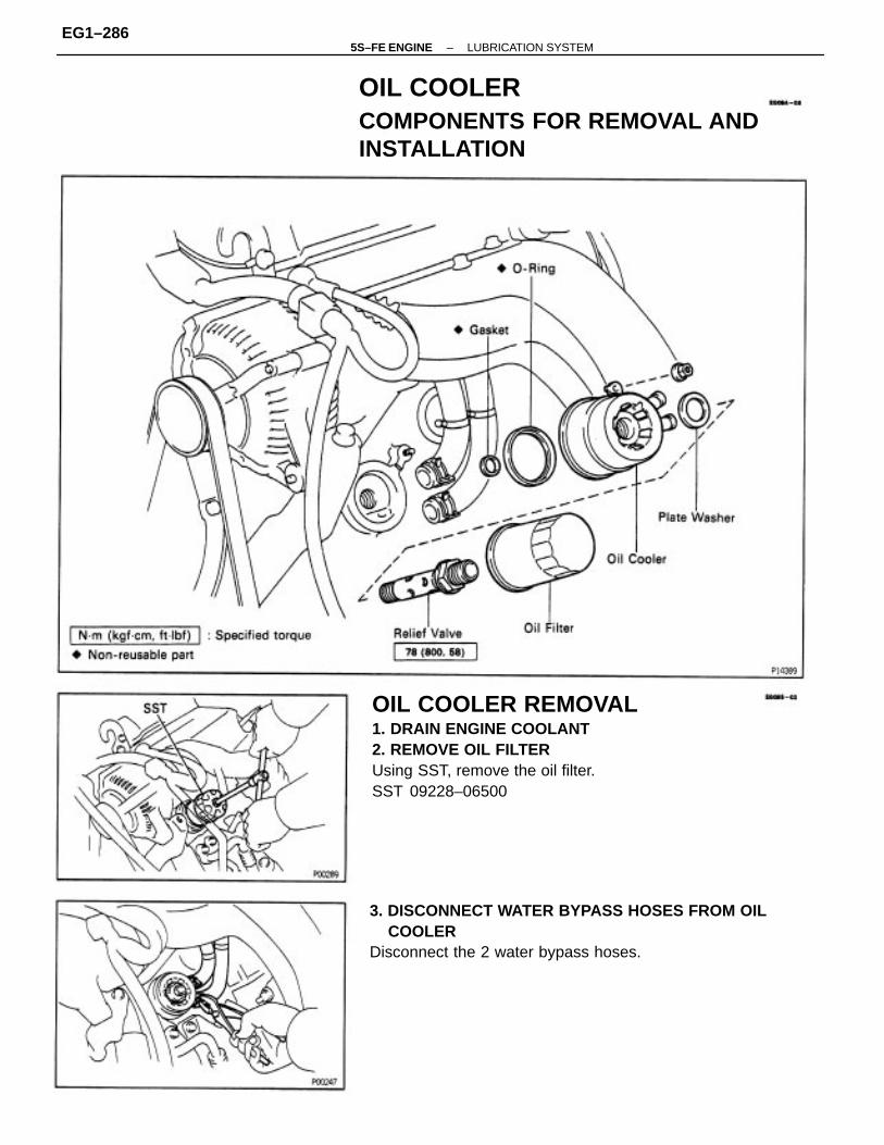
OIL COOLER REMOVAL1. DRAIN ENGINE COOLANT2. REMOVE OIL FILTERUsing SST, remove the oil filter.SST 09228–06500
3. DISCONNECT WATER BYPASS HOSES FROM OIL COOLERDisconnect the 2 water bypass hoses.
OIL COOLERCOMPONENTS FOR REMOVAL ANDINSTALLATION
–5S–FE ENGINE LUBRICATION SYSTEMEG1–286

(b) Apply a light coat of engine oil on the threads andunder the head of the relief valve.
(c) Temporarily install the oil cooler with the nut.(d) Install the plate washer and relief valve.
Torque: 78 N–m (800 kgf–cm, 58 ft–lbf)
(e) Tighten the nut.Torque: 7.8 N–m (80 kgf–cm, 69 In.–lbf)
OIL COOLER INSPECTION1. INSPECT RELIEF VALVEPush the valve with a wooden stick to check if it isstuck.If stuck, replace the relief valve.
OIL COOLER INSTALLATION(See Components for Removal and Installation)1. INSTALL OIL COOLER(a) Install new O–ring and gasket to the oil cooler.
4. REMOVE OIL COOLER(a) Remove the relief valve and plate washer.(b) Remove the nut and oil cooler.(c) Remove the O–ring and gasket from the oil cooler.
2. INSPECT OIL COOLERCheck the oil cooler for damage or clogging.If necessary, replace the oil cooler.
–5S–FE ENGINE LUBRICATION SYSTEMEG1–287

(c) Tighten the oil filter by hand until the rubber gasketcontacts the seat of the filler mounting. Then usingSST, give it an additional 3/4 turn to seat the oil filter.SST 09228–06500
4. FILL WITH ENGINE COOLANT(See page EG1–241)5. START ENGINE AND CHECK FOR LEAKS6. CHECK ENGINE OIL LEVEL
3. INSTALL OIL FILTER(a) Clean the oil filter contact surface on the filter
mounting.
2. CONNECT WATER BYPASS HOSESConnect the 2 water bypass hoses.
(b) Lubricate the filter rubber gasket with engine oil.
–5S–FE ENGINE LUBRICATION SYSTEMEG1–288

SERVICE SPECIFICATIONSSERVICE DATA
TORQUE SPECIFICATIONS
Front exhaust pipe x Center exhaust pipe
Oil cooler x Cylinder block (Relief valve)
Oil pump pulley x Oil pump drive shaft
Oil pump body cover x Oil pump body
No.2 idler pulley x Cylinder block
Oil cooler x Cylinder block (Nut)
Front exhaust pipe x WU–TWC
Stiffener plate x Transaxle case
Stiffener plate x Cylinder block
Oil strainer x Cylinder block
Oil pump x Cylinder block
Oil pan x Cylinder block
Oil strainer x Oil pump
Oil pan x Drain plug
Oil pan x Oil pump
Body clearance
Part tightened
Tip clearance
Oil pressure
Oil pump
–5S–FE ENGINE LUBRICATION SYSTEMEG1–289

5S-FE ENGINE –
-Memo

5S–FE ENGINE TROUBLESHOOTING
–5S–FE ENGINEEG1–291

HOW TO PROCEED WITH TROUBLESHOOTINGThe Engine Control System broadly consists of the sensors, Engine Control Module (ECM) and actuators.The ECM receives signals from various sensors, judges the operating conditions and determines theoptimum injection duration, timing, ignition timing and idle speed.In general, the Engine Control System is considered to be a very intricate system to troubleshoot. But, thefact is that if you proceed to inspect the circuit one by one following the procedures directed in this manu-al, troubleshooting of this system is not complex.This section explains the most ideal method of troubleshooting and tells how to carry out the necessaryrepairs.1. CUSTOMER PROBLEM ANALYSISUsing the customer problem analysis check sheet for reference, ask the customer in as much detailsas possible about the problem.
2. CHECK AND CLEAR DIAGNOSTIC TROUBLE CODE (PRECHECK)Before confirming the problem symptom, first check the diagnostic trouble code and make a note ofany malfunction code which is output, then clear the code.HINT: Output of the malfunction code indicates that there is a malfunction in the circuit indicated.However, it does not indicate whether the malfunction is still occurring or occurred in the past andreturned to normal. In order to determine this, the problem sym toms should be confirmed in step 4first and the diagnostic trouble code be rechecked in step [6].Accordingly, if troubleshooting is begun based on the malfunction code only in diagnostic troublecode check in step [2], it could result in a misdiagnosis, leading to troubleshooting of circuits whichare normal and making it more difficult to locate the cause of the problem.3. SETTING THE TEST MODE DIAGNOSIS, [4] PROBLEM SYMPTOM CONFIRMATION,
[5] SYMPTOM SIMULATIONIn order to find out the trouble more quickly, set the diagnosis check in test mode and with highersensing ability of the ECM, confirm the problem symptoms. If the trouble does not reappear, use thesymptom simulation method to make sure the trouble is reproduced.
6. DIAGNOSTIC TROUBLE CODE CHECK IN TEST MODECheck the diagnostic trouble code in test mode. If the malfunction code is output, proceed to step. If thenormal code is output, proceed to step [7].7. BASIC INSPECTIONCarry out basic inspection such as the spark check and fuel pressure check, etc.8. DIAGNOSTIC TROUBLE CODE CHARTIf the malfunction code is displayed, proceed to inspect the circuit indicated by the chart for eachcode.9. MATRIX CHART OF PROBLEM SYMPTOMSIf the normal code is displayed in the diagnosis in test mode, perform troubleshooting according tothe inspection order in the Matrix Chart of Problem Symptoms.10. PARTS INSPECTIONWhen the Matrix Chart of Problem Symptoms instructs to check the parts, proceed to parts inspectionsection included in this manual.11. CIRCUIT INSPECTIONDetermine if the malfunction is the sensor, actuator, wire harness, connector or the ECM.
–5S–FE ENGINE HOW TO PROCEED WITH TROUBLESHOOTINGEG1–292

CHECK FOR MOMENTARY INTERRUPTIONBy performing the check for momentary interruption, the place where momentary interruptions ormomentary shorts are occurring due to poor contacts can be isolated.
ADJUSTMENT, REPAIRAfter the cause of the problem is located, perform adjustment or repairs by following the inspectionand replacement procedures in this manual.
CONFIRMATION TESTAfter completing adjustment or repairs, confirm not only that the malfunction is eliminated, but alsoconduct a test drive, etc., to make sure the entire Engine Control System is operating normally.
–5S–FE ENGINE HOW TO PROCEED WITH TROUBLESHOOTINGEG1–293

Titles inside are titles of pagesin this manual, with the page numberindicated in the bottom portion.See the indicated pages for detailedexplanations
: Diagnostic steps per–mitting the use of theTOYOTA hand–heldtester or TOYOTAbreak–out–box.
Setting the Test Mode Diagnosis P. EG1–298
Check and clear Diagnostic Trouble Code (Pre-check.)
Check for Momentary Interruption
Malfunction does not occur.
Matrix Chart of Problem Symptoms
Problem Symptom Confirmation
Vehicle Brought to Workshop
Diagnostic Trouble Code Chart
Diagnostic Trouble Code Check
Customer Problem Analysis
Symptom Simulation
Identification of Problem
Circuit Inspection
Malfunctionoccurs:
Adjustment, Repair
Confirmation Test
Parts Inspection
Malfunction code
Basic Inspection
P. EG1–297, 299
P. EG1–309
p.EG1–310
P. EG1–298Normal code
P. EG1–295
P. EG1–327
P. EG1–300
P. EG1–336
P. IN–24
End
Step
–5S–FE ENGINE HOW TO PROCEED WITH TROUBLESHOOTINGEG1–294

CUSTOMER PROBLEM ANALYSIS CHECK SHEET
–5S–FE ENGINE CUSTOMER PROBLEM ANALYSIS CHECK SHEETEG1–295

DIAGNOSIS SYSTEMDESCRIPTIONThe ECM contains a built–in self–diagnosis system by whichtroubles with the engine signal network are detected and aMalfunction indicator lamp on the instrument panel lights up.By analyzing various signals as shown in the later table (Seepage EG1–300) the Engine Control Module (ECM) detectssystem malfunctions relating to the sensors or actuators.In the normal mode, the self–diagnosis system monitors 14items, indicated by code No. as shown in EG1–300. A mal-function indicator lamp informs the driver that a malfunctionhas been detected. The light goes off automatically when themalfunction has been repaired. But the diagnostic troublecode(s) remains stored in the ECM memory (except for codeNos. 16). The ECM stores the code(s) until it is cleared byremoving the EFI fuse with the ignition switch off.The diagnostic trouble code can be read by the number ofblinks of the malfunction indicator lamp when TE1 and E1terminals on the data link connector 1 or 2 are connected.When 2 or more codes are indicated, the lowest number(code) will appear first.In the test mode, 9 items, indicated by code No. as shown inEG1–300 are monitored. If a malfunction is detected in anyone of the systems indicated by code Nos. 13, 22, 24, 25, 26,27, 31, 41 and 71 the ECM lights the malfunction indicatorlamp to warn the technician that malfunction has been de-tected. In this case, TE2 and E1 terminals on the data linkconnector 1 or 2 should be connected as shown later. (Seepage EG1–298). In the test mode, even if the malfunction is corrected, themalfunction code is stored in the ECM memory even whenthe ignition switch is off (except code Nos. 43 and 51). Thisalso applies in the normal mode. The diagnostic mode (nor-mal or test) and the output of the malfunction indicator lampcan be selected by connecting the TE1, TE2 and E1 termi-nals on the data link connector 1 or 2, as shown later. A test mode function has been added to the functions of theself–diagnostic system of the normal mode for the purpose ofdetecting malfunctions such as poor contact, which are diffi-cult to detect in the normal mode. This function fills up theself–diagnosis system. The test mode can be implementedby the technician following the appropriate procedures ofcheck terminal connection and operation described later.(See pageEG1–298)
–5S–FE ENGINE DIAGNOSIS SYSTEMEG1–296

Diagnosis Inspection (Normal Mode)MALFUNCTION INDICATOR LAMP CHECK1. The Malfunction indicator lamp will come on when the
ignition switch is turned ON and the engine is not run–ning.
HINT: If the malfunction indicator lamp does not lightup, proceed to troubleshooting of the combination meter(See page BE–64).
2. When the engine is started, the malfunction indicatorlamp should go off.If the light remains on, the diagnosis system has detecteda malfunction or abnormality in the system.
DIAGNOSTIC TROUBLE CODE CHECK1. Turn ignition switch on.2. Using SST, connect terminals between TE1 and E1 of data link connector 1 or 2.
SST 09843–18020
As an example, the blinking patterns for codes;normal,12 and 31 are as shown on the illustration.4. Check the details of the malfunction using the diagnostic
trouble code table on page EG1–300.5. After completing the check, disconnect terminals TE1
and E1, and turn off the display.HINT: I n the event of 2 or more malfunction codes,indication will begin from the smaller numbered codeand continue in order to the larger.
3. Read the diagnostic trouble code from malfunction indi–cator lamp.
HINT: If a diagnostic trouble code is not output, checkthe TE1 terminal circuit (See page EG1–430).
–5S–FE ENGINE DIAGNOSIS SYSTEMEG1–297

Diagnosis Inspection (Test Mode)Compared to the normal mode, the test mode has high sens–ing ability to detect malfunctions.It can also detect malfunctions in the starter signal circuit, theIDL contact signal of the throttle position sensor, air condi–tioning signal and Park/Neutral Position switch signal.Furthermore, the same diagnostic items which are detected inthe normal mode can also be detected in the test mode.
DIAGNOSTIC TROUBLE CODE CHECK1. Initial conditions.
(a) Battery voltage 11 V or more.(b) Throttle valve fully closed.(c) Transmission in neutral position.(d) Air conditioning switched off.
2. Turn ignition switch off.3. Using SST, connect terminals TE2 and E1 of data link
connector 1 or 2.SST 09843–18020
4. Turn ignition switch on. HINT:
• To confirm that the test mode is operating, check thatthe malfunction indicator lamp flashes when the igni–tion switch is turned to ON.
• If the malfunction indicator lamp does not flash, pro–ceed to troubleshooting of the TE2 terminal circuit onpage EG1–430.
5. Start the engine.6. Simulate the conditions of the malfunction described by
the customer.7. After the road test, using SST, connect terminals TE1 and
E1 of data link connector 1 or 2.SST 09843–18020
8. Read the diagnostic trouble code on malfunction indica–tor lamp on the combination meter (See page EG1–297).
9. After completing the check, disconnect terminals TE1,TE2 and E1, and turn off the display.
HINT:• The test mode will not start if terminals TE2 and E1 are
connected after the ignition switch is turned on.• When vehicle speed is 3 mph (5 km/h) or below,
diagnostic trouble code “42” (Vehicle speed signal) isoutput, but this is not abnormal.
• When the engine is not cranked, diagnostic troublecode “43” (Starter signal) output, but this is not ab–normal.
• When the automatic transmission shift lever is in the“D”, “2”, “L” or “R” shift position, or when the airconditioning is on or when the accelerator pedal isdepressed, code “51” (Switch condition signal) isoutput, but this is not abnormal.
–5S–FE ENGINE DIAGNOSIS SYSTEMEG1–298

ECM DATA MONITOR USING TOYOTAHAND–HELD TESTER1. Hook up the TOYOTA hand–held tester to the D LC2.2. Monitor the ECM data by following the prompts on the
tester screen.HINT: TOYOTA hand–held tester has a “Snapshot”function which records the monitored data.Please refer to the TOYOTA hand–held tester operator’smanual for further details.
ECM TERMINAL VALUES MEASUREMENTUSING TOYOTA BREAK–OUT–BOX ANDTOYOTA HAND–HELD TESTER1. Hook up the TOYOTA break–out–box and TOYOTA
hand–held tester to the vehicle.2. Read the ECM input/output values by following the
prompts on the tester screen.HINT: TOYOTA hand–held tester has “Snapshot” func–tion. This records the measured values and is effective inthe diagnosis of intermittent problems.Please refer to the TOYOTA hand–held tester/Toyotabreak–out–box operator’s manual for further details.
DIAGNOSTIC TROUBLE CODE CLEARANCE1. After repair of the trouble areas, the diagnostic trouble
code retained in the ECM memory must be cleared out byremoving the E F I fuse (15A) from J/13 No. 2 for 10 seconds ormore, with the ignition switch OFF.
HINT:• Cancellation can also be done by removing the battery
negative (–) terminal, but in this case, other memorysystems (clock, etc.) will also be cancelled out.
• If it is necessary to work on engine components requir–ing removal of the battery terminal, a check must firstbe made to see if a diagnostic trouble code has beenrecorded.
2. After cancellation, road test the vehicle to check that anormal code is now read on the malfunction indicatorlamp.If the same diagnostic trouble code appears, it indicatesthat the trouble area has not been repaired thoroughly.
DIAGNOSTIC TROUBLE CODE CHECKUSING TOYOTA HAND–HELD TESTER1. Hook up the TOYOTA hand–held tester to the DLC2.2. Read the diagnostic trouble codes by following the prompts on the tester screen. Please refer to the TOYOTA hand–held tester operator’s manual for further details.
–5S–FE ENGINE DIAGNOSIS SYSTEMEG1–299

DIAGNOSTIC TROUBLE CODE CHARTHINT: Parameters listed in the chart may not be exactly same as your reading due to type of the in-struments or other factors.
No G signal to ECM while NE signal is input 4 times to ECM whenengine speed is between 500 rpm and 4,000 rpm.
No G signal to ECM for 3 sec. or more with engine speed between600 rpm and 4,000 rpm.
* NE signal does not pulse 12 times to ECM during the intervalbetween G1 and G2 pulses.
Fault in communications between the engine CPU and A/T CPUin the ECM
No N E or G 1 and G2 signal to ECM for 2 sec. or more aftercranking.
* No N E signal to ECM for 0.1 sec. or more at 1,000 rpm or more.
No NE signal to ECM for 0.3 sec. or more at 1,500 rpm or more.
No NE signal to ECM within 2 sec. or more after cranking.
* No IGF signal to ECM for 8 consecutive IGT signals.
No IGF signal to ECM for 4 consecutive IGT signals.
G, N E SignalCircuit (No. 1)(Only forCalifornia spec,)
G, NE SignalCircuit (No. 1)(Exc. Californiaspec.)
Diagnostic Trouble Code Detecting Condition
G, NE SignalCircuit (No. 2)
Ignition SignalCircuit
*,* : See page EG1–306
A/T ControlSignal
Open in G (–) circuit
Number ofMIL Blinks
No code is recorded.
DTCNo. Circuit
Normal
–5S–FE ENGINE DIAGNOSTIC TROUBLE CODE CHARTEG1–300

If a malfunction code is displayed during the diagnostic trouble code check in test mode, check the circuitfor that code listed in the table below (Proceed to the page given for that circuit).
• Open or short in IGF or IGT circuit from igniter to ECM• Igniter• ECM
• Open or short in NE, G circuit• Distributor• Open or short in STA circuit
9 ECM
• Open or short in NE circuit• Distributor• ECM
MalfunctionIndicatorLamp*
*,*: See page EG1–306
NormalMode
Trouble Area Memory *
TestMode
See page
EG1–351
EG1–339
• ECM
E G –343
EG1–336
EG1–344
N.A.
N.A.
N.A.
N.A.
N.A.
N.A.
N.A.
–5S–FE ENGINE DIAGNOSTIC TROUBLE CODE CHARTEG1–301

Main oxygen sensor signal voltage is reduced to between 0.35 Vand 0.70 V for 60 sec. under conditions (a) ∼ (d).(2 trip detection logic) *5 (a) Engine coolant temp.: 80C (176F) or more. (b) Engine speed: 1,500 rpm or more. (c) Load driving (Ex. A/T in overdrive (5th for M/T), A/C ON, Flat road, 50 mph (80 km/h)). (d)Main oxygen sensor signal voltage: Alternating above and below 0.45 V.
(2) Engine speed varies by more than 15 rpm over the precedingcrankshaft position period during a period of 50 sec. or more underconditions (a) and (b).(2 trip detection logic)*(a) Engine speed: Idling(b) Engine coolant temp.: 60C (140F) or more.
(1) Main oxygen sensor voltage is 0.45 V or less (lean) for 90sec. under conditions (a) and (b).(2 trip detection logic)*(a) Engine coolant temp.: 60C (140F) or more.(b) Engine speed: 1,500 rpm or more.
Open or short in engine coolant temp. sensor circuit for 0.5 sec.or more.
Open or short in intake air temp. sensor circuit for 0.5 sec. or more.
Diagnostic Trouble Code Detecting Condition
Engine CoolantTemp. SensorSignal
Air–Fuel RatioLean Malfunction
Intake Air Temp.Sensor Signal
Main OxygenSensor Signal
*: See page EG1–307
Number ofMIL Blinks
DTCNo. Circuit
–5S–FE ENGINE DIAGNOSTIC TROUBLE CODE CHARTEG1–302

• Open or short in injector circuit• Fuel line pressure (injector leak, blockage)• Mechanical system malfunction (skipping teeth of timing
belt)• Ignition system• Compression pressure (foreign object caught in valve)• Air leakage• ECM
• Open or short in main oxygen sensor circuit• Main oxygen sensor• ignition system• ECM
• Open or short in engine coolant temp. sensor circuit• Engine coolant temp. sensor• ECM
• Open or short in intake air temp. sensor circuit• Intake air temp. sensor• ECM
• Main oxygen sensor circuit• Main oxygen sensor
MalfunctionIndicatorLamp*
*,*: See page EG1–306
NormalMode
Trouble Area Memory‘
TestMode
See page
EG1–360
EG1–363
EG1–352
EG1–356
–5S–FE ENGINE DIAGNOSTIC TROUBLE CODE CHARTEG1–303

All conditions below are detected continuously for 8 sec. or more.(a) No.1 vehicle speed sensor signal: 0 mph (km/h)(b) Engine speed: Between 3,100 rpm and 5,000 rpm.(e) Engine coolant temp.: 80C (176F) or more.(d) Load driving.
Engine speed varies by more than 15 rpm over the precedingcrankshaft position period during a period of 50 sec. or moreunder conditions (a) and (b),(2 trip detection logic)* (a) Engine speed: Idling (b) Engine coolant temp.:60C (140F) or more.
Main oxygen sensor signal is 0.45 V or more and sub oxygensensor signal is 0.45 V or less under conditions(a) and(b).(2 trip detection logic)*(a) Engine coolant temp.: 80C (176F) or more.(b) Accel. pedal: Fully depressed for 2 sec. or more.
All conditions below are detected continuously for 8 sec. or more.(a) No.1 vehicle speed sensor signal: 0 mph (km/h)(b) Engine speed: 3,100 rpm or more.(c) Park/Neutral position switch: OFF
Open or short in manifold absolute pressure sensor circuitfor 0.5 sec. or more.
Open or short in throttle position sensor circuit for 0.5 sec. or more.
Diagnostic Trouble CodeDetecting Condition
No.1 VehicleSpeed SensorSignal(for M /T)
Manifold AbsolutePressure SensorSignal
No–1 VehicleSpeed SensorSignal(for A/T)
Throttle PositionSensor Signal
Air–Fuel RatioRich Malfunction
Sub OxygenSensor Signal
*: See page EG1–307
Number ofMIL Blinks
DTCNo. Circuit
–5S–FE ENGINE DIAGNOSTIC TROUBLE CODE CHARTEG1–304

• Open or short in injector circuit• Fuel line pressure (injector leak, blockage)• Mechanical system malfunction (skipping teeth of timing
belt)• Ignition system• Compression pressure (foreign object caught in valve)• Air leakage• ECM
• Open or short in No.1 vehicle speed sensor circuit• No.1 vehicle speed sensor• Combination meter• ECM
• Open or short in manifold absolute pressure sensor circuit.• Manifold absolute pressure sensor• ECM
• Open or short in throttle position sensor circuit• Throttle position sensor• ECM
• Open or short in sub oxygen sensor circuit• Sub oxygen sensor• ECM
MalfunctionIndicatorLamp*
*,*: See page EG1–306
NormalMode
Trouble Area Memory* TestMode
See page
EG1–380
EG1–369
EG1–376
EG1–372
EG1–363
OFF OFF
–5S–FE ENGINE DIAGNOSTIC TROUBLE CODE CHARTEG1–305

*1; “ON” displayed in the diagnosis mode column indicates that the Malfunction Indicator Lamp is lighted up when a malfunction is detected. “OFF” indicates that the “CHECK” does not light up during malfunction diagnosis, even if a malfunction is detected. “N.A.” indicates that the item is not included in malfunction diagnosis.*2; “O” in the memory column indicates that a diagnostic trouble code is recorded in the ECM memory when a malfunction occurs. “X” indicates that a diagnostic trouble code is not recorded in the ECM memory even if a malfunction occurs. Accordingly, output of diagnostic results in normal or test mode is performed with the IG switch ON.*3; Only for California specification vehicles.*4; Only vehicles with A/T.
EGR gas temp. is 70C (158F) or below for 50 sec. underconditions (a) and (b).(2 trip detection logic)*(a) Engine coolant temp.: 80C (176F) or more.(b) EGR operation possible (Ex. A/T in 3rd speed (5th forM/T), 55 – 60 mph (88 – 96 km/h), Flat road).
(1) 3 sec. or more after engine starts with closed throttle position switch OFF (IDL).(2) * Park/Neutral switch OFF (PNP). (Shift position in “R”, “D”, “2”, or “L” positions).(3) A/C switch ON.
Open or short in knock sensor circuit with engine speedbetween 1,200 rpm and 6,000 rpm.
Diagnostic trouble CodeDetecting Condition
Switch ConditionSignal
No starter signal to ECM.
Knock SensorSignal
EG R SystemMalfunction
Number ofMIL Blinks
Starter Signal
DTCNo.
Circuit
–5S–FE ENGINE DIAGNOSTIC TROUBLE CODE CHARTEG1–306

*5: This indicates items for which “2 trip detection logic” is used. With this logic, when a logic malfunction is first detected, the malfunction is temporarily stored in the ECM memory. If the same case is detected again during the second drive test, this second detection causes the Malfunction Indicator Lamp to light up. The 2 trip repeats the same mode a 2nd time. (However, the IG switch must be turned OFF between the 1st trip and 2nd trip), In the Test Mode, the Malfunction Indicator Lamp lights up the 1st trip a malfunction is detected.
• open in EGR gas temp. sensor circuit• Short in VSV circuit for EGR• EGR hose disconnected, valve stuck• Clogged EGR gas passage• ECM
• Throttle position sensor IDL circuit• Accelerator pedal and cable• Park/Neutral Position switch circuit• A/C switch circuit• ECM
• Open or short in starter signal circuit• Open or short in ignition switch or starter relay circuit ECM
• Open or short in knock sensor circuit• Knock sensor (looseness).• ECM
MalfunctionIndicatorLamp*
NormalMode
Trouble Area Memory*
TestMode
See page
EG1–390
EG1–385
EG1–396
EG1–383
N.A.
N.A.
N.A.
OFF
OFF
–5S–FE ENGINE DIAGNOSTIC TROUBLE CODE CHARTEG1–307

*: Only for California specification vehicles.Back–Up FunctionIf there is trouble with the program in the ECM and the ignition signals (IGT) are not output frommicrocomputer the ECM controls fuel injection and ignition timing at predetermined levels as a back–upfunction to make it possible to continue to operate the vehicle.Furthermore, the injection duration is calculated from the starting signal (STA) and the throttle positionsignal (IDL). Also, the ignition timing is fixed at the initial ignition timing, 5 BTDC, without relation tothe engine speed.HINT: If the engine is controlled by the back–up function, the malfunction indicator lamp lights up towarn the driver of the malfunction but the diagnostic trouble code is not output.
FAIL–SAFE CHARTIf any of the following codes is recorded, the ECM enters fail–safe mode.
• Ignition timing fixed at 5 BTDC.• Injection time fixed
Starting ..... 12.1 m sec.I D L 0 N ..... 3.3 m sec.IDL OFF .... 6.1 m sec.
• Intake manifold vacuum is fixed at 46.7 kPa.(350 mmHg, 13.8 inHg)
The following must each be repeated at least 2 timeconsecutively.• 0.1 V VTA 0.95 V• IDL : ON
1 IGF detected in consecutive 2 (4*) ignitions.
Fail–Safe Deactivation Conditions
THW is fixed at 80C (176F).
THA is fixed at 20C (68F). Returned to normal condition.
Returned to normal condition.
Returned to normal condition.
Returned to normal condition.
Torque control prohibited.
Max. timing retardation.
Fail–Safe Operation
VTA1 is fixed at 0.
IG switch OFF.
DTC No.
Fuel cut
–5S–FE ENGINE FAIL–SAFE CHARTEG1–308

CLEAR DIAGNOSTIC TROUBLE CODESSee page EG1–299.
SET TEST MODE1. With the ignition switch off, using SST, connect the ter–
minals TE2 and E1 of the data link connector 1 and 2.SST 09843–18020
2. Start the engine and check to see the malfunction indica–tor lamp to go off.
PERFORM A SIMULATION TESTUsing the symptom simulation (See page IN –24), apply vibra–tion to and pull lightly on the wire harness, connector orterminals in the circuit indicated by the malfunction code.In this test, if the malfunction indicator lamp light up, it indi–cates that the place where the wire harness, connector orterminals being pulled or vibrated has faulty contact. Checkthat point for loose connections, dirt on the terminals, poor fitor other problems and repair as necessary.HINT: After cancelling out the diagnostic trouble code inmemory and set the test mode, if the malfunction indicatorlamp does not go off after the engine is started, check thor–oughly for faulty contact, etc., then try the check again. If themalfunction indicator lamp still does not go off, check andreplace ECM.
CHECK FOR MOMENTARYINTERRUPTIONAs described in the preceding paragraph, abnormality detec–tion ability in the test mode is increased compared to that inthe normal mode, so that when momentary interruptions ormomentary shorts occur in the ECM signal circuits (G, NE,THW, THA, PIM, VTA) shown in the table below, the appro–priate diagnostic trouble code is output.Accordingly, when the diagnostic trouble codes shown in thetable below (13, 22, 24, 31, 41) are output during the diag–nostic trouble code check, and inspection of the appropriatecircuits reveals no abnormality, perform the check for momen–tary interruption as described below.By performing the check for momentary interruption, theplace where momentary interruptions or momentary shorts areoccurring due to poor contacts can be isolated.
Engine coolant temp. sensorcircuit
Manifold absolute pressuresensor circuit
Throttle position sensor circuit
Intake air temp. sensor circuit
G, NE signal circuit (No.2)
CircuitDTC
–5S–FE ENGINE CHECK FOR MOMENTARY INTERRUPTIONEG1–309

BASIC INSPECTIONWhen the normal code is displayed in the diagnostic trouble code check, troubleshooting should beperformed in the order for all possible circuits to be considered as the causes of the problems.In many cases, by carrying out the basic engine check shown in the following flow chart, the locationcausing the problem can be found quickly and efficiently. Therefore, use of this check is essential in en-gine troubleshooting.
Remove air filter.
Visually check that the air filter is not excessivelydamaged or oily.
If necessary, clean the air filter with compressedair. First blow from inside thoroughly, then blowoff outside of the air filter.
Is battery positive voltage 11 V or more when engine is stopped?
Proceed to matrix chart of problemsymptoms on page EG1–327.
Is engine cranked ?
Does engine start
Charge or replace battery.
Check air filter.
Repair or replace.
Go to step
Go to step
YES
YES
YES
–5S–FE ENGINE BASIC INSPECTIONEG1–310

(1) Shift transmission into “N” position or neutral.
(2) Warm up engine at normal operating temperature.
(3) Keep the engine speed at idle.
(4) Using SST, connect terminals TE1 and E1 ofdata link connector 1.SST 09843–18020
(5) Using a timing light, connect the tester toNo. 1 high–tension cord.
(1) Shift transmission into “N” position or neutral.
(2) Warm up engine at normal operating temperature.
(3) Switched off all accessories.
(4) Switched off air conditioning.
(5) Connect tachometer test probe to terminalIG (–) of data link connector 1, and set thetachometer to the 4–cylinder range.
• NEVER allow tachometer test probe to touchground as it could result in damage to igniterand/or ignition coil.
• As some tachometers are not compatiblewith this ignition system, we recommendedthat you confirm compatibility of your unit
before use.
Proceed to matrix chart of problem symptomson page EG1–327.
Proceed to page IG–19, 38* and continueto troubleshoot.
Proceed to matrix chart of problemsymptoms on page EG1–327.
*Except California specification vehicles.
Check ignition timing.
Check idle speed.
Check idle speed.
Idle speed: 700 ~ 800 rpm
Check ignition timing.
Ignition timing: 10 BTDC at idle
–5S–FE ENGINE BASIC INSPECTIONEG1–311

(1) Be sure that fuel is enough in tank.(2) Turn ignition switch on.(3) Using SST, connect terminals FP and + B of data link connector 1.SST 09843–18020Check for fuel pressure in the return hose when itis pinched off.
Disconnect the high–tension cord from the distributor and, hold the end about 12.5 mm (1/2”)from the ground, see if spark occurs while the engine is being cranked.
To prevent excessive fuel injected from the injectors during this test, don’t crank the engine formore than 1–2 seconds at a time.
Never make a mistake with the terminal con–nection position as this will cause a malfunc–tion.
Proceed to matrix chart of problem symptomson page EG1–327.
Proceed to page EG1–178 and continueto troubleshoot.
Proceed to page IG–6, 26* and continueto troubleshoot.
* : Except California specification vehicles.
Check fuel pressure.
Check for spark.
At this time, you will hear fuel return noise.
–5S–FE ENGINE BASIC INSPECTIONEG1–312

PARTS LOCATION
–5S–FE ENGINE PARTS LOCATIONEG1–313

WIRING DIAGRAMExcept California specification vehicles.
–5S–FE ENGINE WIRING DIAGRAMEG1–314

–5S–FE ENGINE WIRING DIAGRAMEG1–315

WIRING DIAGRAM (Cont’d)Only for California specification vehicles.
–5S–FE ENGINE WIRING DIAGRAMEG1–316

–5S–FE ENGINE WIRING DIAGRAMEG1–317

TERMINALS OF ECMWhen measuring the voltage or resistance of the connector part of the ECM, always insert the test probeinto the connector from the wire harness side.
ECM (Except California specification vehicles with M/T)
Injectors (No.1 and No.3)
VSV for A/C Idle up
Terminal No.
Terminal No.
Power ground
Starter relay
Connection Connection
Distributor
Distributor
Distributor
Distributor
IAC valve
IAC valve
SymbolSymbol
Igniter
E11– 1 ISCV
–5S–FE ENGINE TERMINALS OF ECMEG1–318

• Manifold absolute pressure sensor
• Throttle position sensor
Manifold absolute pressure sensor
• Defogger relay
• Taillight relay
Engine coolant temp. sensor
Data link connector 1 and 2
Data link connector 1 and 2 Malfunction indicator lamp
Injectors (No.2 and No.4)
No.1 vehicle speed sensor
Throttle position sensor
Throttle position sensor
Intake air temp. sensor
EG R gas temp. sensor
Circuit opening relay
Main oxygen sensor
Data link connector 1
Sub oxygen sensor
Terminal No.
Terminal No.
A/C amplifier
EFI main relay
EFI main relay
Sensor ground
Sensor ground
A/C amplifier
Power ground
ECM ground
ConnectionConnection
VSV for EG R
Knock sensor
SymbolSymbol
Battery
Igniter
–5S–FE ENGINE TERMINALS OF ECMEG1–319

ECM (California specification vehicles and except California specification vehicles with A/T)
*: Only for California specification vehicles.*: Except California specification vehicles with A/T.
• Manifold absolute pressure sensor• Throttle position sensor
TERMINAL OF ECM (Cont’d)
Manifold absolute pressure sensor
VSV for fuel pressure control
Engine coolant temp. sensor
No.2 and No.4 injectors
No.1 and No.3 injectors
Intake air temp. sensor
VSV for A/C Idle up
Main oxygen sensor
Sub oxygen sensor
A/T No.1 solenoid
A/T No,2 solenoid
Terminal No.*
A/T SL solenoid
Power ground
Power ground
No.2 injector
No.1 injector
No.4 injector
No.3 injector
ECM ground
VSV for EG R
ConnectionConnection
Distributor
Distributor
Distributor
Distributor
IAC valve
IAC valve
SymbolSymbol
Igniter
Igniter
Terminal No.*
–5S–FE ENGINE TERMINALS OF ECMEG1–320

*: Only for California specification vehicles.*: Except California specification vehicles with A/T.
• Stoplight switch• Stoplight
• Park/neutral position switch
• Defogger relay• Taillight relay
Park/neutral position switch
Park/neutral position switch
Park/neutral position switch
Malfunction indicator lamp
Data link connector 1 and 2
Data link connector 1 and 2
No.1 vehicle speed sensor
Throttle position sensor
Throttle position sensor
EGR gas temp. sensor
Circuit opening relay
Data link connector 1
Data link connector 2
Cruise control ECU
O/D main switch
Terminal No.
Terminal No.
Connection
A/C amplifier
EFI main relay
Sensor ground
Sensor ground
A/C amplifier
EFI main relay
Knock sensor
Starter relay
ConnectionSymbol Symbol
Battery
–5S–FE ENGINE TERMINALS OF ECMEG1–321

IG switch ON and apply vacuum to thethrottle opener. Throttle valve fully closed.
ECM (Except California specification vehicles with M/T)
STANDARD VALUE OF EC
Idling, Engine coolant temp, 80C (176F)
IG switch 0 NThrottle valve fully closed
IG switch ONThrottle valve fully open
IG switch ONThrottle valve fully open
Idling, Intake air temp. 20C (68F)
Pulse generation(See page EG1–347)
Pulse generation(See page EG1–336)
Pulse generation(See page EG1–336)
Pulse generation(See page EG1–347)
TERMINALS
Symbols (Terminals No.) STD Voltage (V)
Pulse generation
Wiring Color
IG switch ON
IG switch ON
IG switch ON
IG switch ON
IG switch ON
Condition
Below 2.0
Always
Idling
Idling
Idling
Idling
Idling
Idling
–5S–FE ENGINE STANDARD VALUE OF ECM TERMINALSEG1–322

Maintain engine speed at 2,500 rpm for2 minutes after warming up then return toidling
Maintain engine speed at 2,500 rpm for2 minutes after warming up
IG switch ONRotate driving wheel slowly
Pulse generation(See page EG1–355)
Pulse generation(See page EG1–389)
Pulse generation(See page EG1–380)
Symbols (Terminals No.)
A/C switch ON (at idling)
Idling, A/C switch OFF
Idling, A/C switch ON
STD Voltage (V)
A/C switch OFF
Wiring Color
IG switch ON
IG switch ON
IG switch ON
IG switch ON
lG switch ON
Condition
Idling
Idling
–5S–FE ENGINE STANDARD VALUE OF ECM TERMINALSEG1–323

ECM (California specification vehicles and except California specification vehicles with A/T)
STANDARD VALUE OF ECM TERMINALS (Cont’d)
*: Only for California specification vehicles.*: Except California specification vehicles with A/T.
IG switch ON and apply vacuum to thethrottle opener. Throttle valve fully closed.
Idling, Engine coolant temp. 80C (176F)
IG switch ONThrottle valve fully closed
IG switch ONThrottle valve fully open
IG switch ONThrottle valve fully open
Idling, Intake air temp. 20C (68F)
Pulse generation(See page EG1–410)
Pulse generation(See page EG1–341)
Pulse generation(See page EG1–336)
Pulse generation(See page EG1–341)
Pulse generation(See page EG1–347)
Pulse generation(See page EG1–347)
Pulse generation(See page EG1–336)
Symbols (Terminals No.)*3 STD Voltage (V)Wiring Color
IG switch ON
IG switch ON
IG switch ON
IG switch ON
lG switch ON
Condition
Below 2.0
Always
Idling
Idling
Idling
Idling
Idling
Idling
Idling
Idling
–5S–FE ENGINE STANDARD VALUE OF ECM TERMINALSEG1–324

Maintain engine speed at 2,500 rpm for2 minutes after warming up then returnto idling
*: Only for California specification vehicles.
Maintain engine speed at 2,500 rpm for2 minutes after warming up
IG switch ONOther shift position in “P”, “N” position
IG switch ONShift position in “P”, “N” position
IG switch ON0/D main switch pushed out
Restarting at high engine coolant temp.
IG switch ONO/D main switch pushed in
IG switch ONRotate driving wheel slowly
Pulse generation(See page EG1–389)
Pulse generation(See page EG1–380)
Pulse generation(See page EG1–355)
Symbols (Terminals No.)*
A/C switch ON (At idling)
Idling, A/C switch OFF
Idling, A/C switch ON
STD Voltage (V)
A/C switch OFF
Wiring Color
IG switch ON
IG switch ON
IG switch O N
IG switch ON
IG switch ON
IG switch ON
IG switch ON
Condition
Idling
Idling
*:
–5S–FE ENGINE STANDARD VALUE OF ECM TERMINALSEG1–325

REFERENCE VALUE OF ECM DATA
*1: If the engine coolant temp, sensor circuit is open or shorted, the ECM assumes an engine coolant temp, value of 80C (176F).*2: When feedback control is forbidden, 0 V is displayed,*3: A/T only.
Closed throttle positionWide open throttleFrom closed throttle position to wide open throttle
When shifting from “P” or “N” position into a positionother than “P” or “N”
Engine idling at normal operating temp.increase engine load
Engine cold to hotEngine idling at normal operating temp.
RPM stable at 2,500 rpm with normal operating temp.
PRM stable at 2,500 rpm with normal operating temp.
RPM kept stable (Comparison with tachometer)
During driving (Comparison with speedometer)
Below 5Above 70Gradually increases
Approx. 180 ∼ 280 mm HgGradually increases
Engine idling at normal operating temp.
Engine idling at normal operating temp.
Gradually decreasesApprox. 2 ∼ 5 msecs
REFERENCE VALUE
Engine at normal operating temp. 75 – 95C (185 – 203F) *1
Closed throttle position
RICH LEAN is repeated
Increase engine speed
No large differences
Inspection condition
Gradually increases
No great changes
2.50± 1.25 V *2
During cranking
PNP SIGNAL *3
A/C switch ON
ENGINE SPEED
Reference value
TARGET A/F L
VEHICLE SPD
A/F FB LEFT
A/C SIGNAL
STA SIGNAL
CTP SIGNAL
30∼60%
INJECTOR
THROTTLE
IAC DUTY
IGNITION
G EAR
MAP
Item
OxL
ECT
HINT: ECM data can be monitored by TOYOTA hand–heldtester.1. Hook up the TOYOTA hand–held tester to the DLC2.2. Monitor ECM data by following the prompts on the tester
screen.Please refer to the TOYOTA hand–held tester operator’s
manual for further details.
–5S–FE ENGINE REFERENCE VALUE OF ECM DATAEG1–326

MATRIX CHART OF PROBLEM SYMPTOMSWhen the malfunction code is not confirmed in the diagnostic trouble code check and the problem still cannot be confirmed in the basic inspection, then proceed to this step and perform troubleshooting accordingto the numbered order given in the table below.
*: Except California specification vehicles.
Par
k/N
eutr
al p
ositi
on s
witc
h ci
rcui
t
Man
ifold
abs
olut
e pr
essu
re s
enso
r ci
rcui
t
VS
V c
ircui
t for
fuel
pre
ssur
e co
ntro
l
Igni
tion
sign
al c
ircui
t (S
park
test
)
After acceleration pedal depressed
After acceleration pedal released
Sw
itch
cond
ition
sig
nal c
ircui
t
Muffler explosion (after fire)
No initial combustion
Bac
k up
pow
er s
ourc
e ci
rcui
t
Hesitation/Poor acceleration
No complete combustion
EC
M p
ower
sou
rce
circ
uit
Sta
rter
and
Sta
rter
rel
ay
Eng
ine
cont
rol m
odul
e
High engine idle speed
Low engine idle speed
Under normal condition
During A/C operation
Engine does not crank
A/C
cut
con
trol
circ
uit
Sta
rter
sig
nal c
ircui
t
Soon after starting
Fue
l sys
tem
circ
uit
When N to D shift
Incorrect first idle
Poo
rD
rivea
bilit
y
IAC
val
ve c
ircui
t
Diff
icul
t to
star
t
Inje
ctor
circ
uit
Rough idling
Doe
s no
tst
art
Com
pres
sion
Suspect area
Cold engine
Igni
tion
coil
Eng
ine
Sta
ll
EG
R s
yste
m
Hot engine
Poo
r Id
ling
Spa
rk p
lug
A/T
faul
ty
lG–1
0,30
*
IG–1
1,30
Dis
trib
utorSymptom
ST
–19,
21
See page
IG–8
,28*
IG–6
,26*
Hunting
Surging
EG
1–40
0
EG
1–41
0
EG
1–39
0
EG
1–40
3
EG
1–40
8
EG
1–41
5
EG
1–41
9
EG
1–38
3
EG
1–37
2
EG
1–42
8
EG
1–39
6
EG
1 –4
24
AX
1–68
EG
1–23
IN–3
6
–5S–FE ENGINE MATRIX CHART OF PROBLEM SYMPTOMSEG1–327

LOCATION OF CONNECTORSLocation of Connectors in Engine Compartment
–5S–FE ENGINE LOCATION OF CONNECTORSEG1–328

–5S–FE ENGINE LOCATION OF CONNECTORSEG1–329

Location of Connectors in Instrument Panel
–5S–FE ENGINE LOCATION OF CONNECTORSEG1–330

!/B No.1
–5S–FE ENGINE LOCATION OF CONNECTORSEG1–331

Location of Connectors in Instrument Panel (Cont’d)
R/B No.6R/B No.1
J/B No.3
J/B No.1
–5S–FE ENGINE LOCATION OF CONNECTORSEG1–332

Location of Connectors in Body
Coupe
Sedan
–5S–FE ENGINE LOCATION OF CONNECTORSEG1–333

Location of Connectors in Body (Cont’d)
Wagon
–5S–FE ENGINE LOCATION OF CONNECTORSEG1–334

5S-FE ENGINE –
-Memo

CIRCUIT DESCRIPTIONThe distributor in the Engine Control System contains 3 pickup coils.The G signals inform the ECM of the standard crankshaft position.The NE signals inform the ECM of the crankshaft position and the engine speed.
• During cranking or idling, check waveforms between terminals G (+) and G (–),NE (+) and NE (–) of engine control module.
HINT: The correct waveforms appear as shownin the illustration on the left.
• Open or short in NE, G circuit
• Distributor
• Open or short in STA circuit
• ECM
No G signal to ECM for 3 sec. or more withengine speed between 600 rpm and 4,000 rpm.
No N E signal to ECM with 2 sec. or more aftercranking.
CIRCUIT INSPECTION
INSPECTION USING OSCILLOSCOPE
Diagnostic Trouble Code Detecting Condition
Reference
Trouble Area
DTC 12 G NE Signal Circuit (No.1) (Exc. California spec.)
DTC No.
–5S–FE ENGINE CIRCUIT INSPECTIONEG1–336

Check for open and short in harness andconnector between ECM and distributor.
Check resistance of each pickup coils indistributor.
Repair or replace harness or connector.
DIAGNOSTIC CHART
WIRING DIAGRAM
Replace distributor housing.
Replace distributor housing.
Check and replace ECM.
Check air gap.
–5S–FE ENGINE CIRCUIT INSPECTIONEG1–337

Remove distributor cap and rotor.
Using a thickness gauge, measure the air gap be–tween the signal rotor and pickup coil projection.
Air gap: 0.2 – 0.4 mm (0.008 – 0.006 in.)
Check for open and short in harness and connector betweenengine control module and distributor (See page IN–31).
Disconnect distributor connector.
Measure resistance between each terminalshown in table below.
“Cold” is from –10C (14F) to 50C (122F) and“Hot” is from 50C (122F) to 100C (212F).
Check resistance of each pickup coils in distributor.
Check and replace engine control module.
Repair or replace harness or connector.
INSPECTION PROCEDURE
Replace distributor housing.
Replace distributor housing.
NE Pickup Coil(NE (+) – NE (–) )
Check air gap.
G Pickup Coil(G1 –G (–))
475 ~ 650
370 ~ 550
240 ~ 325
185 ~ 275
Resistance
Cold
Cold
Hot
Hot
–5S–FE ENGINE CIRCUIT INSPECTIONEG1–338

CIRCUIT DESCRIPTIONThe distributor in the Engine Control System contains 3 pick–up coils (G1, G2 and NE).The G1, G2 signals inform the ECM of the standard crankshaft angle.The NE signals inform the ECM of the crankshaft angle and the engine speed.
• Open or short in NE, G circuit.• Distributor• Open or short in STA circuit.• ECM
No NE or G1 and G2 signal to ECM for2 sec. or more after cranking.
Diagnostic Trouble Code Detecting Condition
Open in G (–) circuit.
Trouble Area
DTC 12 G NE Signal Circuit (No.1) (Only for California spec.)
DTC No.
–5S–FE ENGINE CIRCUIT INSPECTIONEG1–339

Check for open and short in harness andconnector between ECM and distributor.
Check resistance of each pickup coils indistributor.
Repair or replace harness or connector.
DIAGNOSTIC CHART
WIRING DIAGRAM
Check and replace ECM.
Replace distributor.
Replace distributor.
Check air gap.
–5S–FE ENGINE CIRCUIT INSPECTIONEG1–340

• During cranking or idling, check waveforms be–tween terminals G1, G2, NE and G O of enginecontrol module.
HINT: The correct waveforms appear as shown in theillustration on the left.
Disconnect distributor connector.
Measure resistance between each terminalshown in table below.
Check for open and short in harness and connector betweenengine control module and distributor (See page IN–31).
“Cold” is from –10C (14 F) to 50C (122F) and “Hot” isfrom 50C (122F) to 100C (212F).
Check resistance of each pickup coils in distributor.
INSPECTION USING OSCILLOSCOPE
Repair or replace harness or connector.
INSPECTION PROCEDURE
Replace distributor.
Reference
Resistance
–5S–FE ENGINE CIRCUIT INSPECTIONEG1–341

Remove distributor cap & rotor.
Using SST (G1 and G2 pickups) and a thicknessgauge (NE pickup), measure the air gap betweenthe signal rotor and pickup coil projection.SST 09240–00020 for G1 and G2 pickups
Air gap: 0.2–0.5 mm (0.008–0.020 in.)
Check and replace engine control module.
Replace distributor housing assembly.
Check air gap.
–5S–FE ENGINE CIRCUIT INSPECTIONEG1–342

*: Only for California specification vehicles.
CIRCUIT DESCRIPTIONRefer to G, NE signal circuit (No. 1) on page EG1–336, 339.
No G signal to ECM while N E signal is input 4times to ECM when engine speed is between500 rpm and 4,000 rpm.
* NE signal does not pulse 12 times to ECMduring the interval between G1 and G2 pulses.
* No NE signal to ECM for 0.1 sec. or more at1,000 rpm or more.
No NE signal to ECM for 0.3 sec. or more at1,500 rpm or more.
• Open or short in NE circuit• Distributor• ECM
Diagnostic Trouble Code Detecting Condition Trouble Area
DTC 13 G NE Signal Circuit (No.2)
DTC No.
DIAGNOSISThis code indicates that a momentary interruption of the G, N E signal from the distributor to theECM has occurred, but that it is returned to normal. Note that although this problem may not nec-essarily appear at the time of inspection, it cannot be ignored because this diagnostic trouble codeis output, indicating that there is or was a malfunction in the G, NE signal circuit; this “malfunction”is usually a loose connector.The distributor connector and the N E terminal of the ECM connector must therefore be checkedfor the following:1. Loose connectors2. Dirty connector terminals3. Loose connector terminals
–5S–FE ENGINE CIRCUIT INSPECTIONEG1–343

CIRCUIT DESCRIPTIONThe ECM determines the ignition timing, turns on Tr, at a predetermined angle (’*CA) before thedesired ignition timing and outputs an ignition signal (IGT) “1” to the igniter.Since the width of the IGT signal is constant, the dwell angle control circuit in the igniter determinesthe time the control circuit starts primary current flow to the ignition coil based on the engine rpm andignition timing one revolution ago, that is, the time the Tr2 turns on.When it reaches the ignition timing, the ECM turns Tr, off and outputs the IGT signal “O”.This turns Tr2 off, interrupting the primary current flow and generating a high voltage in the secondarycoil which causes the spark plug to spark. Also, by the counter electromotive force generated whenthe primary current is interrupted, the igniter sends an ignition confirmation signal (IGF) to the ECM.The ECM stops fuel injection as a fail safe function when the lG F signal is not input to the ECM.
• Open or short in IG F or IGT circuit from
igniter to ECM.
• Igniter
• ECM
No IGF signal to ECM for 4 (8*2) consecutiveIGT signals.
Diagnostic Trouble Code Detecting Condition
WIRING DIAGRAM
Trouble Area
DTC 14 Ignition Signal Circuit
DTC No.
–5S–FE ENGINE CIRCUIT INSPECTIONEG1–344

Check for open and short in IGF signal circuitbetween igniter and ECM.
Check for open and short in IGT signal circuitbetween igniter and ECM.
Check voltage of terminal IGT (Disconnectigniter connector).
Check for open and short in primary coilcircuit.
Check and repair igniter powersource circuit.
Repair or replace harness orconnector.
Repair or replace harness orconnector.
Repair or replace harness orconnector.
Check voltage of igniter power source.
DIAGNOSTIC CHART
Check voltage of terminal I G F.
Check voltage of terminal IGT.
Check and replace ECM.
Check and replace ECM.
Replace ignition coil.Check ignition coil.
Check for spark.
Replace igniter.
Replace igniter.
Replace igniter.
–5S–FE ENGINE CIRCUIT INSPECTIONEG1–345

Disconnect the high–tension cord from the distributor, hold its end about 12.5 mm (11 /2”)from the ground, see if spark occurs while the engine is being cranked.
Spark should be generated.
To prevent excessive fuel injected from the injectors during this check, don’t crank theengine for more than 1 – 2 seconds at a time.
(1) Disconnect igniter connector.(2) Remove glove compartment.
(See page EG1–234).(3) Turn ignition switch on.
Measure voltage between terminal IGF of enginecontrol module connector and body ground.
Voltage: 4.5 ∼ 5.5 V
Check for open and short in harness and connector in IGF signalcircuit between engine control module and igniter (See page IN–31).
Disconnect igniter connector and check voltage between terminalIGF of engine control module connector and body ground.
Check and replace engine control module.
Repair or replace harness or connector.
INSPECTION PROCEDURE
Check for spark.
Replace igniter.
Go to step
–5S–FE ENGINE CIRCUIT INSPECTIONEG1–346

Remove glove compartment.(See page EG1–234) .
Measure voltage between terminal IGT of enginecontrol module connector and body groundwhen engine is cranked.
Voltage: 0.5 – 1.0 V(Neither 0 V nor 5 V)
• During cranking or idling, check waveform betweenterminal IGT and E1 of engine control module.
HINT: The correct waveform appears as shown in theillustration on the left, with rectangle waves.
Check voltage between terminal IGT of engine control moduleconnector and body ground.
INSPECTION USING OSCILLOSCOPEReference
Go to step
–5S–FE ENGINE CIRCUIT INSPECTIONEG1–347

Disconnect igniter connector.
Measure voltage between terminal 3 of igniterconnector and body ground, when ignitionswitch is turned to “ON” and “STA” position.
Voltage: 9 ∼ 14 V
Check for open and short in harness and connector between ignitionswitch and ignition coil, ignition coil and igniter (See page IN–31).
Check voltage between terminal 3 of igniter connector and bodyground.
Check and repair igniter power sourcecircuit.
Repair or replace harness or connector.
–5S–FE ENGINE CIRCUIT INSPECTIONEG1–348

For California spec.(1) Disconnect ignition coil connector.
(2) Disconnect high–tension cord from ignitioncoil.Exc. California spec.
(1) Disconnect distributor connectors.
(2) Remove distributor cap and rotor.
(3) Remove ignition coil dust cover.(1) Check primary coil.Measure resistance between the positive(+) and negative (–) terminals.(2) Check secondary coil.Measure resistance between the positive(+) and high–tension terminals.
“Cold” is from –10C (14F) to 50C (122F) and“Hot” is from 50C (122F) to 100C (212F).
Check ignition coil.
Replace ignition coil.
Replace igniter.
SecondaryCoil
PrimaryCoil
Resistance
Cold
Cold
Hot
Hot
–5S–FE ENGINE CIRCUIT INSPECTIONEG1–349

Disconnect igniter connector.
Measure voltage between terminal IGT of enginecontrol module connector and body groundwhen engine is cranked.
Voltage: 0.5–1.0 V (Neither 0 V nor 5 V)
Check for open and short in harness and connector in IGT signalcircuit between engine control module and igniter (See page IN–31).
Disconnect igniter connector and check voltage between terminalIGT of engine control module connector and body ground.
Check and replace engine control module.
Repair or replace harness or connector.
Replace igniter.
–5S–FE ENGINE CIRCUIT INSPECTIONEG1–350

CIRCUIT DESCRIPTIONThe signal from the A/T CPU retards the ignition timing of the engine during A/T shifting, thusmomentarily reducing torque output of the engine for smooth clutch operation inside the transmis-sion and reduced shift shock.
If the ECM detects the diagnostic trouble code “16” in memory, it prohibits the torque control of theA/T which performs smooth gear shifting.
Are there any other codes (besides Code 16)being output?
Fault in communications between the engineCPU and A/T CPU in the ECM
Go to relevant diagnostic trouble codechart.
Diagnostic Trouble Code Detecting Condition
DIAGNOSTIC CHART
Replace ECM.
Trouble Area
DTC 16 A–T Control Signal Malfunction
DTC No.
• ECM
YES
–5S–FE ENGINE CIRCUIT INSPECTIONEG1–351

CIRCUIT DESCRIPTIONTo obtain a high purification rate for the C0, HC and NOx components of the exhaust gas, a three–way catalytic converter is used, but for most efficient use of the three–way catalytic converter, theair–fuel ratio must be precisely controlled so that it is always close to the stoichiometric air–fuel ra-tio. The oxygen sensor has the characteristic whereby its output voltage changes suddenly in thevicinity of the stoichiometric air–fuel ratio. This characteristic is used to detect the oxygen con-centration in the exhaust gas and provide feedback to the computer for control of the air–fuel ratio.When the air–fuel ratio becomes LEAN, the oxygen concentration in the exhaust increases and theoxygen sensor informs the ECM of the LEAN condition (small electromotive force; 0 V).When the air–fuel ratio is RICHER than the stoichiometric air–fuel ratio the oxygen concentration inthe exhaust gas is reduced and the oxygen sensor informs the ECM of the RICH condition (largeelectromotive force: 1 V). The ECM judges by the electromotive force from the oxygen sensorwhether the air–fuel ratio is RICH or LEAN and controls the injection time accordingly. However, ifmalfunction of the oxygen sensor causes output of abnormal electromotive force, the ECM is un-able to perform accurate air–fuel ratio control.
Main oxygen sensor signal voltage is reduced tobetween 0.35 V and 0.70 V for 60 sec. underconditions (a) – (d). (2 trip detection logic) * (a) Engine coolant temp. : 80C (176F) or more. (b) Engine speed : 1,500 rpm or more. (c) Load driving (EX. A/T in overdrive (5th for M/T), A/C ON, Flat road, 50 mph (80km/h)). (d) Main oxygen sensor signal voltage : Alternating above and below 0.45 V.
Diagnostic Trouble Code Detecting Condition
• Main oxygen sensor circuit.
• Main oxygen sensor.
*See page EG1–307
Trouble Area
DTC 21 Main Oxygen Sensor Circuit
DTC No.
–5S–FE ENGINE CIRCUIT INSPECTIONEG1–352

Disconnect the EFI fuse (15A) for 10 sec. or more, with IG switch OFF.Initiate test mode (Connect terminal TE2 and E1 of data link connector 1 or 2 with IG switchOFF).Start the engine and warm up with all ACC switch OFF.
After the engine is warmed up, let it idle for 3 min.
After performing the idling in (3) , perform gradual acceleration with in the range1,300∼1,700 rpm (centered around 1,500 rpm) with the A/C switch ON and D position for A/T(5th for M /T).(Take care that the engine speed does not fall below 1,200 rpm when shifting. Gradually depress the accelerator pedal and keep it. Steady so that engine braking does not occur).
Maintain the vehicle speed at 40 – 50 mph (64 – 80 km/h).Keep the vehicle running for 1 – 2 min. after starting acceleration.HINT: If a malfunction exists, the malfunction indicator lamp will light up after approx.60 sec. from the start of acceleration.
NOTICE: If the conditions in this test are not strictly followed, detection of the mal-function will not be possible.
CIRCUIT DESCRIPTION (Cont’d)DIAGNOSIS TROUBLE CODE DETECTION DRIVING PATTERNPurpose of the driving pattern.
(a) To simulate diagnostic trouble code detecting condition after diagnostic trouble code isrecorded.
(b) To check that the malfunction is corrected when the repair is completed confirming that diag-nostic trouble code is no longer detected.
Malfunction: Main Oxygen Sensor Deterioration
–5S–FE ENGINE CIRCUIT INSPECTIONEG1–353

Are there any other codes (besides code 21)being output ?
Go to relevant diagnostic trouble codechart.
DIAGNOSTIC CHART
WIRING DIAGRAM
Replace main oxygen sensor.
YES
–5S–FE ENGINE CIRCUIT INSPECTIONEG1–354

• With the engine racing (4,000 rpm) measure wave–form between terminals OX1 and E1 of engine con–trol module.
HINT: The correct waveform appears as shown in theillustration on the left, oscillating between approx. 0.1 Vand 0.9 V.
If the oxygen sensor is deteriorated, the amplitude ofthe voltage is reduced as shown on the left.
INSPECTION USING OSCILLOSCOPEReference
–5S–FE ENGINE CIRCUIT INSPECTIONEG1–355

CIRCUIT DESCRIPTIONThe engine coolant temperature sensor senses theengine coolant temperature. A thermistor built in thesensor changes its resistance value according to theengine coolant temperature. The lower the enginecoolant temperature, the greater the thermistor resis–tance value, and the higher the engine coolant tem–perature, the lower the thermistor resistance value(See Fig. 1.).The engine coolant temperature sensor is connectedto the ECM (See next page). The 5 V power sourcevoltage in the ECM is applied to the engine coolanttemperature sensor from the terminal THW via a resis-tor R. That is, resistor R and the engine coolant tem–perature sensor are connected in series. When theresistance value of the engine coolant temperaturesensor changes in accordance with changes in theengine coolant temperature, the potential at the ter–minal THW also changes. Based on this signal, theECM increases the fuel injection volume to improvedriveability during cold engine operation. If the ECMdetects the diagnostic trouble code 22, it operates thefail safe function in which the engine coolant temper–ature is assumed to be 80C (176F).
• Open or short in engine coolant temp,
sensor circuit
• Engine coolant temp. sensor
• ECM
Open or short in engine coolant temp. sensorcircuit for 0.5 sec. or more.
Diagnostic Trouble Code Detecting Condition
Engine coolantTemp. C (F)
Resistance (k)
( Reference )
Voltage (V)
Trouble Area
100 (212)
DTC 22 Engine coolant Temp. Sensor Circuit
60 (140)
40 (104)
80 (176)
–20 (–4)
DTC No.
20 (68)
0 (32)
16.0
0.9
0.3
0.6
0.2 0.3
0.5
4.3
2.5
3.45.9
2.4
–5S–FE ENGINE CIRCUIT INSPECTIONEG1–356

DIAGNOSTIC CHARTHINT If diagnostic trouble codes “22” (engine coolant temperature sensor circuit), “24” (intake air temperature sensor cir-
cuit), “31” (manifold absolute pressure sensor circuit) and “41” (throttle position sensor circuit) are output simultaneously, E2
(sensor ground) may be open, OK Check for momentary interruption
Check for open and short in harness and connectorbetween ECM and engine coolant temp. sensor.
Check for momentary interruption(See page EG1–309).
Repair or replace harness orconnector.
Replace engine coolant temp. sensor.
WIRING DIAGRAM
Check resistance of sensor.
Check and replace ECM.
Check voltage of sensor.
–5S–FE ENGINE CIRCUIT INSPECTIONEG1–357

INSPECTION PROCEDUREHINT: If diagnostic trouble codes “22” (engine coolant temperature sensor circuit), “24” (intake airtemperature sensor circuit), “31” (manifold absolute pressure sensor circuit) and “41 “ (throttleposition sensor circuit) are output simultaneously, E2 (sensor ground) may be open,
(1) Remove glove compartment(See page EG1–234)(2) Turn ignition switch on.Measure voltage between terminals THW and E2 of enginecontrol module connector.
Check voltage between terminals THW and E2 of engine controlmodule connector.
Check for momentary interruption(See page EG1–309)
Engine Coolant Temp. C (F)
20 (68)( Engine is cool )
80 (176)(Engine is hot) 0.2 ∼1.0 v
0.5 ∼ 3.4 V
Voltage
–5S–FE ENGINE CIRCUIT INSPECTIONEG1–358

Check for open and short in harness and connector between enginecontrol module and engine coolant temp. sensor (See page IN–31).
Disconnect the engine coolant temp. sensor con–nector.Measure resistance between terminals.Resistance is within Acceptable Zone on chart.
Check engine coolant temp. sensor.
Check and replace engine control module.
Repair or replace harness or connector.
Replace engine coolant temp. sensor.
Engine coolantTemp. C (F)
0.2 – 0.4 k
Resistance
80(176)
20(68) 2 – 3 k
–5S–FE ENGINE CIRCUIT INSPECTIONEG1–359

DIAGNOSTIC CHARTHINT: If diagnostic trouble codes “22” (engine coolant temperature sensor circuit), “24” (intake air temperature sensor circuit), “31” (manifold absolute pressure sensor circuit) and “41” (throt– tle position sensor circuit) are output simultaneously, E2 (sensor ground) may be open.
CIRCUIT DESCRIPTIONThe intake air temp. sensor is built into the air cleaner cap and senses the intake air tempera-ture. The structure of the sensor and connection to the ECM is the same as in the engine coolanttemp. sensor shown on page EG1–356.If the ECM detects the diagnostic trouble code “24”, it operates the fail safe function in which theintake air temperature is assumed to be 20C (68F)
• Open or short in intake air temp. sensor circuit.
• Intake air temp. sensor
• ECM
Check for open and short in harness andconnector between ECM and intake air temp.sensor.
Open or short in intake air temp. sensor circuitfor 0.5 sec. or more.
Check for momentaryinterruption (See page EG1–309).
Diagnostic Trouble Code Detecting Condition
Repair or replace harness orconnector.
Replace intake air temp. sensor.
WIRING DIAGRAM
Check resistance of sensor.
Check and replace ECM.
Check voltage of sensor.
Trouble Area
DTC 24 Intake Air Temp. Sensor Circuit
DTC No.
–5S–FE ENGINE CIRCUIT INSPECTIONEG1–360

(1) Remove glove compartment. (See page EG1–234)(2) Turn ignition switch on.Measure voltage between terminals THA and E2of engine control module connector.
Check voltage between terminals THA and E2 of engine controlmodule connector.
Check for momentary interruption(See page EG1–309).
INSPECTION PROCEDURE
Intake air temp. °C (°F)
0.5 ∼ 3.4 V
0.2 ∼ 1.0 V60 (140)
20 (68)
Voltage
–5S–FE ENGINE CIRCUIT INSPECTIONEG1–361

Check for open and short in harness and connector betweenengine control module and intake air temp. sensor (See page IN–31).
Disconnect the air temp. sensor connector.
Measure resistance between terminals.
Resistance is within Acceptable Zone on chart.
Check intake air temp. sensor.
Check and replace engine control module.
Repair or replace harness or connector.
Replace intake air temp. sensor.
Intake air temp.°C (° F)
0.4 – 0.7 k
Resistance
60 (140)
20(68) 2 –3k
–5S–FE ENGINE CIRCUIT INSPECTIONEG1–362

CIRCUIT DESCRIPTIONThe main oxygen sensor is located in the exhaust manifold.It indirectly determines whether the fuel mixture is rich or lean by detecting the concentration ofoxygen present in the exhaust gas.
Engine speed varies by more than 15 rpm overthe preceding crank position period during a periodof 50 sec. or more under conditions (a) and (b).(2 trip detection logic) * (a) Engine speed: Idling (b) Engine coolant temp.: 60C (140F) or more
(2) Engine speed varies by more than 15 rpm over the preceding crank position period during a period of 50 sec. or more under conditions (a) and (b). (2 trip detection logic) * (a) Engine speed: Idling (b) Engine coolant temp.: 60C (140F) or more.
• Open or short in injector circuit• Fuel line pressure (injector leak, blockage)• Mechanical system malfunction
(skipping teeth of timing belt)• Ignition system• Compression pressure
(foreign object caught in valve)• Air leakage• ECM
• Open or short in injector circuit• Fuel line pressure (injector leak, blockage)• Mechanical system malfunction
(skipping teeth of timing belt)• Ignition system• Compression pressure
(foreign object caught in valve)• Air leakage• ECM
(1) Main oxygen sensor voltage is 0.45 V or less (lean) for 90 sec. under conditions (a) and (b). (2 trip detection logic) * (a) Engine coolant temp.: 60C (140F) or more. (b) Engine speed: 1,500 rpm or more.
• Open or short in main oxygen sensor circuit• Main oxygen sensor• Ignition system• ECM
Diagnostic Trouble Code Detecting Condition
*: See page EG1–307
Trouble Area
DTC 25 26 Air–Fuel Ratio Lean Rich Malfunction
DTC No.
–5S–FE ENGINE CIRCUIT INSPECTIONEG1–363

H I NT: Before this test, check the feedback voltage for oxygen sensor. Disconnect the EFI fuse (15 A) for 10 sec. or more, with IG switch OFF. Initiate test mode (Connect terminal TE2 and E1 of data link connector 1 or 2 with IG switch OFF). Start engine and warm up. After the engine is warmed up, let it race at 2,500 rpm for 3 min. After performing the racing in (3) , perform idling 1 min.HINT: If a malfunction exists, the malfunction indicator lamp will light up during step (4).
NOTICE: If the conditions in this test are not strictly followed, detection of the malfunctionwill not be possible.
CIRCUIT DESCRIPTION (Cont’d)DIAGNOSIS TROUBLE CODE DETECTION DRIVING PATTERNPurpose of the driving pattern.(a) To simulate diagnostic trouble code detecting condition after diagnostic trouble code is recorded.(b) To check that the malfunction is corrected when the repair is completed confirming that diagnostic
trouble code is no longer detected.
Malfunction: Open or Short in Main Oxygen Sensor. Open or Short in Injector Circuit, Injector Leak or Blockage.
–5S–FE ENGINE CIRCUIT INSPECTIONEG1–364

WIRING DIAGRAMRefer to page EG1–354 for the WIRING DIAGRAM.
Does malfunction disappear when a good mainoxygen sensor is installed?
Check each item found to be a possible causeof problem.
Does malfunction disappear when a good mainoxygen sensor is installed?
Check each item found to be a possible causeof problem.
Check for open and short in harness andconnector.
Repair or replace harness orconnector.
DIAGNOSTIC CHART
Check voltage of terminal OX1.
Check voltage of terminal VF1.
Replace main oxygen sensor.
Replace main oxygen sensor.
Check and replace ECM.
Check and replace ECM.
Check compression.
Check compression.
Repair or replace.
Repair or replace.
Repair or replace.
Repair or replace.
N G
Typ
eΙΙ
NG Type I
YES
YES
–5S–FE ENGINE CIRCUIT INSPECTIONEG1–365

(1) Warm up engine at normal operating tem–perature.(2) Connect terminals TE1 and E1 of data linkconnector 1.(3) Connect positive prove to terminal VF1 andnegative prove to terminal E1 of data linkconnector 1.(1) Warm up the oxygen sensor by running en–gine at 2,500 rpm for about 2 minutes.(2) Then, maintaining engine at 2,500 rpm,count how many times needle of voltmeterfluctuates between 0 and 5 V.
Warm up engine at normal operating temperature.
Measure voltage between terminals OX1 and E1of data link connector 1 when engine is suddenlyraced to full throttle.
The voltage should be 0.5 V or higher at leastonce.
Perform inspection within 1 second.
Check voltage between terminals OX1 and E1 of data link connector 1.
Check voltage between terminals VF1 and E1 of data link connector 1.
Needle fluctuates of 8 times or morefor every ten seconds
INSPECTION PROCEDURE
Continue at 0 V
Continue at 5 V
NGType ΙΙ
Go to step
Go to step NGType Ι
NG Type ΙΙ
NG Type ΙΙ
Result
–5S–FE ENGINE CIRCUIT INSPECTIONEG1–366

Check each circuit found to be a possible cause of trouble according to the results of the check in or . The numbers in the table below show the order in which the checks should be performed.
Check for open and short in harness and connector between engine control module andmain oxygen sensor, engine control module and data link connector 1 (See page IN–31).
Does malfunction disappear when a good main oxygen sensor isinstalled?
Check each item found to be a possible cause of problem.
Check compression (See page EG1–23).
Repair or replace harness or connector.
Check and replace engine control module.
Characteristics deviation inmanifold absolute pressure sensor.
Characteristics deviationin engine coolant temp. sensor.
Replace main oxygen sensor.
*: Except California specification vehicles.
Characteristics deviationin intake air temp. sensor.
Main oxygen sensorsignal continue at OV.
Repair or replace.
Repair or replace.
Faulty sensor installation.
Possible Cause
Injector circuit
Valve timing
Fuel system
Air leakage
See page
IG–6, 26*
YES
EG1–410
EG1–360
EG1–419
EG1–372
EG1–173
EG1–356
Misfire
EG1–36
–5S–FE ENGINE CIRCUIT INSPECTIONEG1–367

Check each circuit found to be a possible cause of trouble according to the results of the check in .The numbers in the table below show the order in which the checks should be performed.
Does malfunction disappear when a good main oxygen sensor isinstalled?
Check each item found to be a possible cause of problem.
Check compression (See page EG1–23).
Check and replace engine control module.
Characteristics deviationin engine coolant temp. sensor.
Characteristics deviation inmanifold absolute pressure sensor.
Replace main oxygen sensor.
Main oxygen sensorsignal continue at 5.0 V.
x: Except California specification vehicles.
Characteristics deviationin intake air temp. sensor.
Main oxygen sensorsignal is normal.
Repair or replace.
Repair or replace.
Possible Cause
Injector circuit
Valve timing
Fuel system
Air leakage
See page
IG–6, 26*
YES
EG1–410
EG1–360
EG1–419
EG1–372
EG1–173
EG1–356
Misfire
EG1–36
–5S–FE ENGINE CIRCUIT INSPECTIONEG1–368

CIRCUIT DESCRIPTIONThe sub oxygen sensor is installed on the exhaust pipe. Its construction and operation is the same asthe main oxygen sensor on page EG1–352.
Main oxygen sensor signal is 0.45 V or moreand sub oxygen sensor signal is 0.45 V or lessunder conditions (a) and (b).(2 trip detection logic) *(a) Engine coolant temp. : 80C (1 76F) or more.(b) Accel. pedal : Fully depressed for 2 sec. or more.
• Open or short in sub oxygen sensor circuit.• Sub oxygen sensor• ECM
Diagnostic Trouble Code Detecting Condition
* : See page EG1–307.
Trouble Area
DTC 27 Sub Oxygen Sensor Circuit
DTC No.
–5S–FE ENGINE CIRCUIT INSPECTIONEG1–369

Disconnect the E F I fuse (15 A) for 10 sec. or more, with IG switch OFF.Initiate test mode (Connect terminals TE2 and E1 of data link connector 1 or 2with I G switch OFF).Start the engine and warm up, with all ACC switch OFF.After the engine is warmed up, let it drive at 50 ∼ 55 mph (80 ∼ 88 km/h)for 10 min. or more.After driving, stop at a safe place and perform idling for 2 min. or less.After performing the idling in (4) , perform acceleration to 60 mph (96 km/h)with the throttle valve fully open.HINT: If a malfunction exists, the malfunction indicator lamp will light up duringstep.
NOTICE: If the conditions in this test are not strictly followed, detection of themalfunction will not be possible.
CIRCUIT DESCRIPTION (Cont’d)DIAGNOSIS TROUBLE CODE DETECTION DRIVING PATTERNPurpose of the driving pattern.
(a) To simulate diagnostic trouble code detecting condition after diagnostic trouble code isrecorded.
(b) To check that the malfunction is corrected when the repair is completed confirming that diagnos–tic trouble code is no longer detected.
Malfunction: Open or Short in Sub Oxygen Sensor
–5S–FE ENGINE CIRCUIT INSPECTIONEG1–370

Are there any other codes (beside Code 27)being output?
Go to relevant diagnostic troublecode chart.
DIAGNOSTIC CHART
WIRING DIAGRAM
Replace sub oxygen sensor.
YES
–5S–FE ENGINE CIRCUIT INSPECTIONEG1–371

CIRCUIT DESCRIPTIONBy a built–in sensor unit, the manifold absolutepressure sensor detects the intake manifold absolutepressure as a voltage.The ECM then determines the basic injection dura–tion and basic ignition advance angle based on thisvoltage.Since the manifold absolute pressure sensor doesnot use the atmospheric pressure as a criterion, butsenses the absolute pressure inside the intake man–ifold (the pressure in proportion to the preset abso–lute vacuum O), it is not influenced by fluctuationsin the atmospheric, pressure due to high altitudeand other factors. This permits it to control the air–fuel ratio at the proper level under all conditions.
If the ECM detect diagnostic trouble code “31 “, it operates the fail safe function, keeping the ignitiontiming and fuel injection volume constant and making it possible to drive the vehicle.
• Open or short in manifold absolute pressure
sensor circuit.
• Manifold absolute pressure sensor.
• ECM
Open or short in manifold absolute pressure sensorcircuit for 0.5 sec. or more.
Diagnostic Trouble Code Detecting Condition Trouble Area
DTC 31 Manifold Absolute Pressure Sensor Circuit
DTC No.
–5S–FE ENGINE CIRCUIT INSPECTIONEG1–372

Check for open and short in harness andconnector between manifold absolute pressuresensor and ECM.
Check and replace manifold absolute pressuresensor.
When diagnostic trouble code 31 isdisplayed, check and replace ECM.
Repair or replace harness orconnector.
DIAGNOSTIC CHART
Check voltage of terminal PIM.
Check voltage of terminal VC. Check and replace ECM.
DIA RAMWIRING DIAGRAM
–5S–FE ENGINE CIRCUIT INSPECTIONEG1–373

(1) Remove glove compartment.(See page EG1–234).(2) Turn ignition switch on.
Measure voltage between terminals VC and E2 ofengine control module connector.
Voltage: 4.5 ∼ 5.5 V
Check voltage between terminals VC and E2 of engine controlmodule connector.
Check and replace engine control module.
INSPECTION PROCEDURE
–5S–FE ENGINE CIRCUIT INSPECTIONEG1–374

Check for open and short in harness and connector between enginecontrol module and manifold absolute pressure sensor(See page IN–31).
Turn ignition switch on
Check voltage between terminals PIM and E2 of engine controlmodule connector.
Check and replace manifold absolute pressuresensor.
When diagnostic trouble code 31 is dis-played, check and replace engine controlmodule.
Repair or replace harness or connector.
Voltage: 13 – 3.9 V
Measure voltage between terminals PI Mand E2 of engine control module connector.
–5S–FE ENGINE CIRCUIT INSPECTIONEG1–375

CIRCUIT DESCRIPTION
HINT;• When the connector for the throttle position sensor is disconnected, diagnostic trouble code 41
is not displayed. Diagnostic trouble code 41 is displayed only when there is an open or short inthe VTA signal circuit of the throttle position sensor.
• Open or short in throttle position sensor circuit.
• Throttle position sensor.
• ECM
Open or short in throttle position sensor circuitfor 0.5 sec. or more.
Diagnostic Trouble Code Detecting Condition Trouble Area
DTC 41 Throttle Position Sensor Circuit
DTC No.
The throttle position sensor is mounted in the throttlebody and detects the throttle valve opening angle. Whenthe throttle valve is fully closed, the I D L contacts in thethrottle position sensor are on, so the voltage at the ter–minal I D L of the ECM become 0 V. At this time, a voltageof approximately 0.7 V is applied to the terminal VTA ofthe ECM. When the throttle valve is opened, the I D Lcontacts go off and thus the power source voltage ofapproximately 12 V in the ECM is applied to the terminalIDL of the ECM. The voltage applied to the terminal VTAof the ECM increases in proportion to the opening angleof the throttle valve and becomes approximately 3.2 –4.9 V when the throttle valve is fully opened. The ECMjudges the vehicle driving conditions from these signalsinput from the terminals VTA and IDL, and uses them asone of the conditions for deciding the air–fuel ratio cor–rection, power increase correction and fuel–cut control etc.
–5S–FE ENGINE CIRCUIT INSPECTIONEG1–376
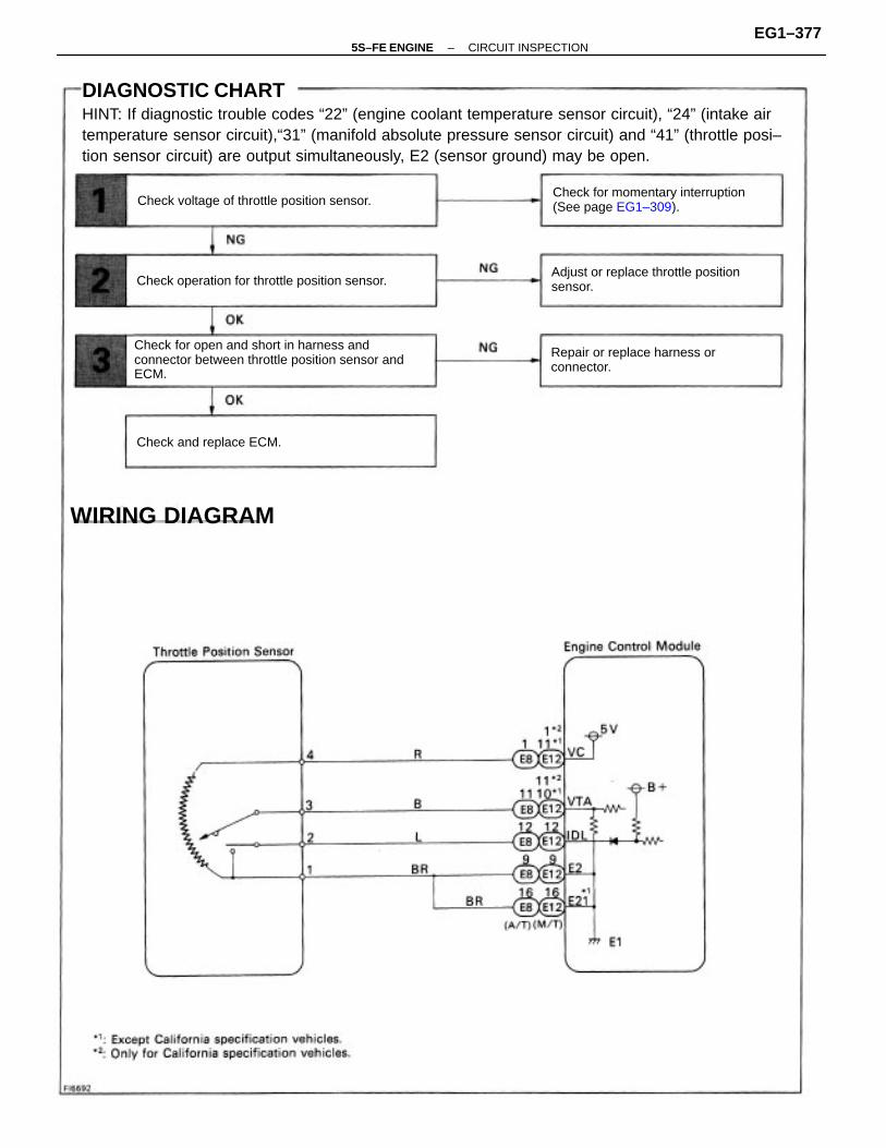
DIAGNOSTIC CHARTHINT: If diagnostic trouble codes “22” (engine coolant temperature sensor circuit), “24” (intake airtemperature sensor circuit),“31” (manifold absolute pressure sensor circuit) and “41” (throttle posi–tion sensor circuit) are output simultaneously, E2 (sensor ground) may be open.
Check for open and short in harness andconnector between throttle position sensor andECM.
Check for momentary interruption(See page EG1–309).
Adjust or replace throttle positionsensor.
Repair or replace harness orconnector.
Check operation for throttle position sensor.
Check voltage of throttle position sensor.
WIRING DIAGRAM
Check and replace ECM.
–5S–FE ENGINE CIRCUIT INSPECTIONEG1–377

INSPECTION PROCEDUREHINT: If diagnostic trouble code “22” (engine coolant temperature sensor circuit), “24” (intake airtemperature sensor circuit), “31” (manifold absolute pressure sensor circuit) and “41 “ (throttleposition sensor circuit) are output simultaneously, E2 (sensor ground) may be open.
(1) Remove glove compartment. (See page EG1–234).(2) Disconnect the vacuum hose from the throt– tle body, then apply vacuum to the throttle opener (See page EG1–204).(3) Turn ignition switch ON.Measure voltage between terminals VTA, IDL andE2 of engine control module connector when thethrottle valve is opened gradually from the closedcondition.
Check voltage between terminals VTA, IDL and E2 of enginecontrol module connector.
The voltage should increase steadily in propor–tion to the throttle valve opening angle.
Check for momentary interruption(See page EG1–309).
Throttle Valve
Fully Closed
Fully Open
VTA – E2Terminal
IDL – E2
–5S–FE ENGINE CIRCUIT INSPECTIONEG1–378

(1) Disconnect throttle position sensor connector.(2) Disconnect the vacuum hose from the throt–tle body, then apply vacuum to the throttleopener (See page EG1–204).
Check for open and short in harness and connector between enginecontrol module and throttle position sensor (See page IN–31).
Resistance between terminals 3 (VTA) and 1(E2) should increase gradually in accordancewith the throttle valve opening angle.
Adjust or replace throttle position sensor (See page EG1–209).
Check throttle position sensor.
Check and replace engine control module.
Repair or replace harness or connector.
3 (VTA) – 1 (E2) 2 (IDL) – 1 (E2)Throttle Valve
Fully Closed
Fully Open
Terminal
Measure resistance between terminals 3 (VTA), 2(IDL) and 1 (E2) of throttle position sensor con–nector when the throttle valve is opened gradu–ally from the closed condition.
–5S–FE ENGINE CIRCUIT INSPECTIONEG1–379

CIRCUIT DESCRIPTIONThe No.1 vehicle speed sensor outputs a 4–pulse signal for every revolution of the rotor shaft,which is rotated by the transmission output shaft via the driven gear. After this signal is convertedinto a more precise rectangular waveform by the waveform shaping circuit inside the combinationmeter, it is then transmitted to the ECM. The ECM determines the vehicle speed based on the fre-quency of these pulse signals.
For M /TAll conditions below are detected continuouslyfor 8 sec. or more. (a) No.1 vehicle speed signal: 0 mph (km/h) (b) Engine speed: Between 3,100 rpm and 5,000 rpm (c) Engine coolant temp.: 80C (176F) or more (d) Load driving
• Waveform between terminals SPD and E1 when vehiclespeed is approx. 12 mph (20 km/h).
HINT: The greater the vehicle speed, the greater the num– ber of No.1 vehicle speed sensor signals produced.
For A/TAll conditions below are detected continuouslyfor 8 sec. or more. (a) No.1 Vehicle speed signal: 0 mph (km/h) (b) Engine speed: 3,100 rpm or more (c) Park/Neutral position switch: OFF
HINT: In test mode, diagnostic trouble code 42 is output when vehicle speed is 3 mph (5 km/h)or below.
• Open or short in No.1 vehicle speed sensorcircuit.
• No.1 vehicle speed sensor.• Combination meter.• ECM
Diagnostic Trouble Code Detecting Condition Trouble Area
DTC 42 No.1 Vehicle Speed Sensor Signal Circuit
DTC No.
–5S–FE ENGINE CIRCUIT INSPECTIONEG1–380

Check speedometer circuit.(See page BE–66).
Check speedometer circuit.(See page BE–66).
DIAGNOSTIC CHART
Check operation of speedometer.
WIRING DIAGRAM
Check voltage of terminal SPD.
Check and replace ECM.
–5S–FE ENGINE CIRCUIT INSPECTIONEG1–381

(1) Remove glove compartment.(See page EG1–234).(2) Disconnect cruise control ECU connector.(3) Shift the shift lever to N position or neutral.(4) Jack up a front wheel on one side.(5) Turn ignition switch on.
Drive the vehicle and check if the operation of the speedometer in the combination meter isnormal.The No. 1 vehicle speed sensor is operating normally if the speedometer display is normal.
Check voltage between terminal SPD of engine control moduleconnector and body ground.
Check speedometer circuit. See combinationmeter troubleshooting on page BE–66.
Check speedometer circuit. See combinationmeter troubleshooting on page BE–66.
Check operation of speedometer.
Check and replace engine control module.
INSPECTION PROCEDURE
Measure voltage between terminal SPD ofengine control module connector and bodyground when the wheel is turned slowly.
Voltage is generated intermittently.
–5S–FE ENGINE CIRCUIT INSPECTIONEG1–382

CIRCUIT DESCRIPTIONWhen the engine is cranked, the intake air flow is slow, so fuel vaporization is poor. A rich mixtureis therefore necessary in order to achieve good startability. While the engine is being cranked, thebattery positive voltage is applied to terminal STA of the ECM. The starter signal is mainly used toincrease the fuel injection volume for the starting injection control and after–start injection control.
DIAGNOSTIC CHARTHINT: This diagnostic chart is based on the premise that the engine is cranked normally. If theengine is not cranked, proceed to the matrix chart of problem symptoms on page EG1–327,
• Open or short in starter signal circuit.
• Open or short in ignition switch or starter
relay circuit.
• ECM
Check for open in harness and connectorbetween ECM and relay.
Proceed to next circuit inspectionshown on matrix chart (See pageE–G–327).
Diagnostic Trouble Code Detecting Condition
Repair or replace harness orconnector.
WIRING DIAGRAM
No starter signal to ECM.
Check and replace ECM.
Check for the test mode.
Trouble Area
DTC 43 Starter Signal Circuit
DTC No.
–5S–FE ENGINE CIRCUIT INSPECTIONEG1–383

Setting the test mode.(1) Turn ignition switch OFF.(2) Connect terminals TE2 and E1 of DLC2.(3) Turn ignition switch ON.(Don’t start the engine)(4) Connect terminals TE1 and E1 of DLC2.
Check for open in harness and connector between engine controlmodule and starter relay (See page IN–31).
Check output condition of diagnostic trouble code 43.
Proceed to next circuit inspection shown onmatrix chart (See page EG1–327).
Check and replace engine control module.
Repair or replace harness or connector.
INSPECTION PROCEDURE
Check if code “43” is output by the malfunc-tion indicator lamp.
Code “43” is output.
Start the engine.Check if the code “43” disappear.
Code “43” is not output.
–5S–FE ENGINE CIRCUIT INSPECTIONEG1–384

If the ECM detects the above diagnosis conditions, it operates the fail safe function in which thecorrective retard angle value is set to the maximum value.DIAGNOSIS TROUBLE CODE DETECTION DRIVING PATTERNPurpose of the driving pattern .
(a) To simulate diagnostic trouble code detecting condition after diagnostic trouble code isrecorded.
(b) To check that the malfunction is corrected when the repair is completed confirming that diag-nostic trouble code is no longer detected.
Start engine and warm up.After engine is warmed up, let it idle for 3 min.With the A/C ON, perform quick racing (5,000 rpm) 3 times.(Rapidly depress the accelerator pedal and suddenly release it.)HINT: If a malfunction exists, the malfunction indicator lamp will light up when suddenracing is performed.
NOTICE: If the conditions in this test are not strictly followed, detection of the mal-function will not be possible.
CIRCUIT DESCRIPTIONKnock sensor is fitted the cylinder block to detect engine knocking. This sensor contains a piezoelec-tric element which generates a voltage when it becomes deformed, which occurs when the cylinderblock vibrates due to knocking. If engine knocking occurs, ignition timing is retarded to suppress it.
• Open or short in knock sensor circuit.
• Knock sensor (looseness)
• ECM
Open or short in knock sensor circuit with enginespeed between 1,200 rpm and 6,000 rpm.
Malfunction: Open or Short in Knock Sensor
Diagnostic Trouble Code Detecting Condition Trouble Area
DTC 52 Knock Sensor Circuit
DTC No.
–5S–FE ENGINE CIRCUIT INSPECTIONEG1–385

Does malfunction disappear when a good knocksensor is installed?
Check for open and short in harness andconnector between knock sensor and ECM.
Repair or replace harness orconnector.
Check no continuity of knock sensor circuit.
DIAGNOSTIC CHART
WIRING DIAGRAM
Check and replace ECM.
Replace knock sensor.
Replace knock sensor.Check knock sensor.
YES
–5S–FE ENGINE CIRCUIT INSPECTIONEG1–386

(1) Remove glove compartment.(See page EG1–234)
(2) Disconnect the engine control module con–nector.
Check continuity between terminal KNK of engine control moduleconnector and body ground.
INSPECTION PROCEDURE
Go to step
Measure resistance between terminal KNKof engine control module connector andbody ground.Resistance: 1 M or higher
–5S–FE ENGINE CIRCUIT INSPECTIONEG1–387

Disconnect knock sensor connector.
Check for open and short in harness and connector between enginecontrol module and knock sensor (See page IN–31).
Does malfunction disappear when a good knock sensor is installed?
Check and replace engine control module.
Replace knock sensor (See page EG1–93).
Replace knock sensor (See page EG1–93).
Repair or replace harness or connector.
Check knock sensor.
YES
Measure resistance between the knocksensor terminal and body.
Resistance: 1 M or higher
–5S–FE ENGINE CIRCUIT INSPECTIONEG1–388

• Spread the time on the horizontal axis, andconfirm that period of the wave is 132 sec.(Normal mode vibration frequency of knocksensor: 7.6 KHz).
HINT: If normal mode vibration frequency is not 7.6 KHz, the sensor is malfunctioning.
• With the engine racing (4,000 rpm) measurewaveform between terminal KN K of enginecontrol module and body ground.
HINT: The correct waveform appears as shown in the illustration on the left.
INSPECTION USING OSCILLOSCOPEReference
–5S–FE ENGINE CIRCUIT INSPECTIONEG1–389

CIRCUIT DESCRIPTIONThe EGR system recirculates exhaust gas, which is controlled to the proper quantity to suit thedriving conditions, into the intake air mixture to slow down combustion, reduce the combustiontemperature and reduces NOx emissions. The amount of EGR is regulated by the EGR vacuummodulator according to the engine load.If even one of the following conditions is fulfilled,the VSV is turned ON by a signal from the ECM.This results in atmospheric air acting on the EGRvalve, closing the EGR valve and shutting off theexhaust gas (EGR cut–OFF).Under the following conditions, EGR is cut tomaintain driveability.• Engine coolant temp. below 60C (140F).• During deceleration (throttle valve closed).• Light engine load (amount of intake air very
small).• Engine speed over 4,400 rpm.• Engine racing.
EG R gas temp. is 70C (158F) or below for 50sec. under conditions (a) and (b). (2 trip detection logic) * (a) Engine coolant temp.: 80C (176F) or more. (b) EGR operation possible (EX. A/T in 3rd speed (5th for M/T), 55 – 60 mph (88 – 96 km/h), Flat road).
• Open in EGR gas temp. sensor circuit.• Short in VSV circuit for EGR.• EGR hose disconnected, valve stuck.• Clogged EGR gas passage.• ECM
Diagnostic Trouble Code Detecting Condition
*: See page EG1–307.
Trouble AreaDTC No.
DTC 71 EGR System Malfunction
–5S–FE ENGINE CIRCUIT INSPECTIONEG1–390

Disconnect the EFI fuse (15 A) for 10 sec. or more, with IG switch OFF. Initiatetest mode (Connect terminals TE2 and E1 of data link connector, 1 or 2 with IGswitch OFF).
CIRCUIT DESCRIPTION (Cont’d)
DIAGNOSIS TROUBLE CODE DETECTION DRIVING PATTERNPurpose of the driving pattern.
(a) To simulate diagnostic trouble code detecting condition after diagnostic trouble code isrecorded.
(b) To check that the malfunction is corrected when the repair is completed confirming that diag-nostic trouble code is no longer detected.
Malfunction: Open in EGR gas temp. sensor circuit
Start the engine and warm up.After the engine is warmed up, let it idle for 3 min.With the A/C ON and transmission in 5th gear A/T in “D” position), drive at55 – 60 mph (88 – 96 km/h) for 4 min. or less.HINT: If a malfunction exists, the malfunction indicator lamp will light up dur-ing step (4) .
NOTICE: If the conditions in this test are not strictly observed, detection ofthe malfunction will not be possible.
–5S–FE ENGINE CIRCUIT INSPECTIONEG1–391

Check for open and short in harness andconnector between EFI main relay and ECM.
Check for open in harness and connectorbetween EGR gas temp. sensor and ECM.
Check voltage of VSV for EGR Power source.
Repair or replace harness orconnector.
Repair or replace harness orconnector.
Check resistance of EGR gas temp. sensor.
Check EGR system (See page EG1–153) .
WIRING DIAGRAM
DIAGNOSTIC CHART
Check resistance of VSV for EG R.
Replace EGR gas temp. sensor.
Check and replace ECM.
Check and replace ECM.
Replace VSV for EG R.
Repair EGR system.
–5S–FE ENGINE CIRCUIT INSPECTIONEG1–392

(1) Remove glove compartment.(See page EG1–234).(2) Warm up engine to normal operating temperature.
Check voltage between terminal EGR of engine control moduleconnector and body ground.
INSPECTION PROCEDURE
Go to step
Measure voltage between terminal EGR of en-gine control module connector and body ground.
Voltage: 9 –14 V
–5S–FE ENGINE CIRCUIT INSPECTIONEG1–393

Remove VSV for EGR. (See page EG1–154, 155*).Measure resistance between terminals of VSV forEG R.
Check for open and short in harness and connector between EFImain relay and VSV for EGR, VSV and engine control module. (See page IN–31).
Check resistance between terminals of VSV for EGR.
Check EGR system (See page EG1–153).
Check and replace engine control module.
Repair or replace harness or connector.
Replace VSV for EGR.
Repair EGR system.
Resistance: 33 – 39 (Cold)*: Except California specification vehicle.
–5S–FE ENGINE CIRCUIT INSPECTIONEG1–394

Remove EGR gas temp. sensor.Measure resistance between terminals of EG Rgas temp. sensor connector.Resistance: 64 – 97 k at 50C (122F) 11 –16 k at 100C (212F) 2 – 4 k at 150C (302F)
Check for open in harness and connector between EGR gas temp.sensor and engine control module (See page IN–31).
Check resistance of EGR gas temp, sensor.
Check and replace engine control module.
Repair or replace harness or connector.
Replace EGR gas temp. sensor.
–5S–FE ENGINE CIRCUIT INSPECTIONEG1–395

CIRCUIT DESCRIPTIONPark/Neutral Position Switch Signal*The ECM uses the signals from the park/neutral position switch to determine whether the transmis–sion is in park or neutral, or in some other gear.Air Conditioning Switch SignalThe ECM uses the output from the air conditioning switch to determine whether or not the airconditioning is operating so that it can increase the idling speed of the engine if necessary.Throttle Position Sensor IDL SignalThe IDL contacts are mounted in the throttle position sensor, and detects the idle condition.
(1) 3 sec. or more after engine starts with closed throttle position switch OFF (IDL).(2) * Park/ Neutral position switch OFF. (Shift position in “R”, “D”, “2” or “L” positions).(3) A/C switch ON.
*: Only vehicles with A/T.HINT: In this circuit, diagnosis can only be made in the test mode.
• Throttle position sensor IDL circuit• Accelerator pedal and cable• Park/Neutral position switch circuit• A/C switch circuit• ECM
Diagnostic Trouble Code Detecting Condition
DIAGNOSTIC CHART
WIRING DIAGRAM
Trouble Area
DTC 51 Switch Condition Signal Circuit
DTC No.
–5S–FE ENGINE CIRCUIT INSPECTIONEG1–396

Check and repair harness or connector betweensensor and ECM.
Proceed to next circuit inspection shown onmatrix chart (See page EG1–327).
Check for open and short in harness andconnector between A/C amplifier and ECM.
Adjust or replace throttle position sensor(See page EG1–209).Check resistance of throttle position sensor.
Repair or replace harness or connector.
DIAGNOSTIC CHART
Check and replace A/C amplifier.Check input circuit of A/C.
NG (PNP)
NG (A/C)
Check and replace ECM.
Check for input signal. See page EG1–400.
NG
(ID
L)
–5S–FE ENGINE CIRCUIT INSPECTIONEG1–397

Setting the test mode.(1) Turn ignition switch OFF.
(2) Connect terminals TE2 and E1 of DLC2.
(3) Turn ignition switch ON.(For checking terminal IDL, disconnect thevacuum hose from the throttle body, thenapply vacuum to the throttle opener (See pageEG1–204).)(For checking terminal A/C, start the engine.)
(4) Connect terminals TE1 and E1 of DLC2.
*: Before the STA signal is input (ST is not ON),diagnostic trouble code 43 is also output.
Check output condition of diagnostic trouble code 51.
Proceed to next circuit inspection shown onmatrix chart (See page EG1–327).
IDL .... Go to stepA/C ... Go to step
INSPECTION PROCEDURE
PN P ... Go to page EG1–400.
Park/Neutral PositionSwitch (PNP)
Accelerator pedaldepressed
Accelerator pedalreleasedThrottle Position
Sensor ( IDL)
R, D, 2 or L position
A/C Switch (A/C)
P or N position
A/C SW OFF
A/C SW ON
Condition
Normal*
Normal*
Normal
Code
51*
51*
Check if code “51” is output by the malfunc-tion indicator lamp.
Diagnostic trouble code 42 is output with vehiclespeed 3 mph (5 km/h) or below.
–5S–FE ENGINE CIRCUIT INSPECTIONEG1–398

(1) Remove glove compartment(See page BO–114).
(2) Disconnect A/C amplifier connector.
(3) Turn ignition switch on.Measure voltage between terminal AC2 of A/C
amplifier connector and body ground.
(1) Disconnect throttle position sensor connec–tor.(2) Disconnect the vacuum hose from the throt–tle body, then apply vacuum to the throttleopener (See page EG1–204).Measure resistance between terminals 2 (IDL)and 1(E2) of throttle position sensor connector.
Check for open and short in harness and connector betweenengine control module and A/C amplifier (See page IN–31).
Disconnect A/C amplifier connector, check voltage betweenterminal AC2 of A/C amplifier connector and body ground.
Check and repair harness or connector betweenengine control module and throttle position sensor.
Adjust or replace throttle position sensor(See page EG1–209).
Check resistance of throttle position sensor.
Check and replace engine control module.
Repair or replace harness or connector.
Check and replace A/C amplifier.
1 M or higher
Less than 2.3 k
Throttle Valve
Fully closed
Resistance
Opened
Voltage: 9 –14 V
–5S–FE ENGINE CIRCUIT INSPECTIONEG1–399

CIRCUIT DESCRIPTIONThe Park/Neutral position switch goes on when the shift lever is in the N or P shift position. Whenit goes on the terminal NSW of the ECM is grounded to body ground via the starter relay and theftdeterrent ECU, thus the terminal NSW voltage becomes 0V. When the shift lever is in the D, 2, L orR position, the Park/Neutral position switch goes off, so the voltage of ECM terminal NSW becomesbattery voltage, the voltage of the ECM internal power source. If the shift lever is moved from the N posi-tion to the D position, this signal is used for air–fuel ratio correction and for idle speed control (estimatedcontrol), etc. When the Park/Neutral position switch is off, code “51” is output in the test mode diagnosis.(This is not abnormal.)
Park Neutral Position Switch Circuit (Only vehicles withA–T)
Check for open in harness and connectorbetween park/neutral position switch and ECM.
Check output condition of diagnostic troublecode 51.
Proceed to next circuit inspection shownon matrix chart (See age EG1–327).
Check park/neutral position switch.(See page AX1–92)
Repair or replace harness or connector.
Replace park/neutral position switch.
Check and replace ECM.
Check and replace ECM.
N G
Typ
e ΙΙ
NG
Type
Ι
DIAGNOSTIC CHARTHINT: This diagnosis chart is based on premise that the engine is cranked normally. If the engineis not cranked, proceed to the matrix chart of problem symptoms on page EG1–327.
–5S–FE ENGINE FE ENGINE TROUBLESHOOTING – CIRCUITINSPECTION
EG1–400

WIRING DIAGRAM
–5S–FE ENGINE CIRCUIT INSPECTIONEG1–401

(1) Connect terminals TE2 and E1 of DLC2.(2) Turn ignition switch on.
(3) Crank the engine.
(4) Connect terminals TE1 and E1 of DLC2.Check if diagnostic trouble code “51” is outputwhen the shift lever is in the P and D shift positions.
Check for open in harness and connector between engine controlmodule and park/neutral position switch (See page IN–31).
Check park/neutral position switch (See page AX1–92).
Check output condition of diagnostic trouble code 51.
Proceed to next circuit inspection shown onmatrix chart (See age EG1–327).
Replace park/neutral position switch.
Check and replace engine control module.
Check and replace engine control module.
Repair or replace harness or connector.
INSPECTION PROCEDURE
NGType ΙΙ
NGType Ι
ShiftPosition
Go to step
Go to step
Normal Code
Normal Code
Normal Code
NG Type ΙΙN G Type Ι
Code 51
Code 51
Code 51
Result
”D”
“P”
–5S–FE ENGINE CIRCUIT INSPECTIONEG1–402

CIRCUIT DESCRIPTIONWhen the ignition switch is turned on, battery positive voltage is applied to the coil, closing thecontacts of the EFI main relay and supplying power to the terminals + B and + 131 of the ECM.
Check for open in harness and connectorbetween IG switch and EFI main relay, EFI mainrelay and body ground.
Check for open in harness and connectorbetween EFI main relay and battery, EFI mainrelay and ECM.
Check continuity between terminal E1 andbody ground.
Proceed to next circuit inspection shownon matrix chart (See page EG1–327).
Check for short in all the harness andcomponents connected to IGN fuse.
Check for short in all the harness andcomponents connected to EFI fuse.
ECM Power Source Circuit
Repair or replace harness or connector.
Repair or replace harness or connector.
Check voltage of ECM power source.
DIAGNOSTIC CHART
Replace ignition switch.
Check EFI fuse.
Replace EFI main relay.
Check ignition switch.
Check EFI main relay.
Check IGN fuse.
–5S–FE ENGINE CIRCUIT INSPECTIONEG1–403

WIRING DIAGRAM
–5S–FE ENGINE CIRCUIT INSPECTIONEG1–404

(1) Remove glove compartment.(See page EG1–234)
(2) Turn ignition switch ON.
Measure voltage between terminals + B, + 131and E1 of engine control module connector.Voltage: 9 –14 V
Check for open in harness and connector between terminal E1 ofengine control module and body ground (See page IN–31).
Check voltage between terminals + B, + 131 and E1 of engine controlmodule connector.
Proceed to next circuit inspection shown onmatrix chart (See page EG1–327).
Repair or replace harness or connector.
INSPECTION PROCEDURE
–5S–FE ENGINE CIRCUIT INSPECTIONEG1–405

Remove EFI main relay from J/B No–2.Check continuity between terminals of EFI mainrelay shown below.
Remove IGN fuse from J/B No.1.
Check continuity of IGN fuse.
(1) Apply battery voltage between terminals 1and 2.
(2) Check continuity between terminals 3 and 5.
Check for short in all the harness andcomponents connected to IGN fuse (Seeattached wiring diagram).
Check EFI main relay.
Continuity(Reference value 72)
Replace EFI main relay.
Check IGN fuse.
Terminals 3 and 5
Terminals 1 and 2
Terminals 3 and 5 Continuity
Open
Continuity
–5S–FE ENGINE CIRCUIT INSPECTIONEG1–406

Check for open in harness and connector between IG switch andEFI main relay, EFI main relay and body ground (See page IN–31).
Remove EFI fuse from J/B No.2.Check continuity of EFI fuse.Continuity
Check for open in harness and connectorbetween EFI main relay and battery, EFI mainrelay and engine control module.
Check for short in all the harness andcomponents connected to EFI fuse (Seeattached wiring diagram).
Remove under cover and finish panel.Check continuity between terminals.
Repair or replace harness or connector.
Check ignition switch.
Replace ignition switch.
Check EFI fuse.
Switch position
continuity
10AM2
Terminal 4AM1
3ACC
6ST2
7ST1
9IG2
START
2lG1
LOCK
ACC
–5S–FE ENGINE CIRCUIT INSPECTIONEG1–407

CIRCUIT DESCRIPTIONBattery positive voltage is supplied to terminal BATT of the ECM even when the ignition switch is offfor use by the diagnostic trouble code memory and air–fuel ratio adaptive control value memory, etc.
Back Up Power Source Circuit
Proceed to next circuit inspectionshown on matrix chart (See page EG1–327).
Check and repair harness or connectorbetween battery, EFI fuse and ECU.
Check for short in all the harness andcomponents connected to EFI fuse.
DIAGNOSTIC CHART
Check operation for the back up.
Check voltage of terminal6ATT.
WIRING DIAGRAM
Check and replace ECM.
Check EFI fuse.
–5S–FE ENGINE CIRCUIT INSPECTIONEG1–408

Remove glove compartment.(See page EG1–234)Measure voltage between terminal BATT of en–gine control module connector and body ground.Voltage: 9 –14 V
Check voltage between terminal BATT of engine control moduleconnector and body ground.
Are the diagnostic trouble codes still in the memory when theignition switch is turned OFF?
Check and repair harness or connectorbetween engine control module and ENfuse, EFI fuse and battery.
Remove EFI fuse from J/B No.2.Check continuity of EFI fuse.Continuity
Check for short in all the harness andcomponents connected to EFI fuse(See attached wiring diagram).
Proceed to next circuit inspection shown onmatrix chart (See page EG1–327).
Check and replace engine control module.
INSPECTION PROCEDURE
Check EFI fuse.
Others
YES
–5S–FE ENGINE CIRCUIT INSPECTIONEG1–409

Reference INSPECTION USING OSCILLOSCOPEINJECTOR SIGNAL WAVEFORM
• With the engine idling measure waveform between terminals #10, #20 (#1, #2, #3 and #4*)and E01 of engine control module.
HINT: The correct waveform appears as shown in the illustration on the below.
CIRCUIT DESCRIPTIONThe injectors are provided to the intake manifold. They inject fuel into the cylinders based on thesignals from the engine control module.
Check continuity between terminals E01, E02and body ground.
Check voltage of terminals #10 and #20(#1. #2. #3 and #4*).
Check for open in harness and connectorbetween ECM and battery.
Check for short in all the harness andcomponents connected to AM2 fuse.
*: Only for California specification vehicles.
Injector Circuit
Repair or replace harness or connector.
DIAGNOSTIC CHART
Check operation for injectors.
Check and replace ECM.
Replace injector.
Check AM2 fuse.
–5S–FE ENGINE CIRCUIT INSPECTIONEG1–410

WIRING DIAGRAMExcept California specification vehicles.
Only for California specification vehicles.
–5S–FE ENGINE CIRCUIT INSPECTIONEG1–411

(1) Remove glove compartment.(See page EG1–234)
(2) Turn ignition switch ON.Exc. California spec.Measure voltage between terminals #10, #20 ofengine control module connector and bodyground.Only for California spec,Measure voltage between terminals #1, #2, #3and #4 of engine control module connector andbody ground.Voltage: 9 –14 V
Check voltage between terminals #10, #20 (#1, #2, #3 and #4) ofengine control module connector and body ground.
INSPECTION PROCEDURE
Go to step
–5S–FE ENGINE CIRCUIT INSPECTIONEG1–412

Check for open in harness and connector between terminals E01, E02of engine control module connector– and body ground (See page IN–31).
Remove AM2 fuse from J/B No. 2.Check continuity of AM2 fuse.Continuity
Check for open in harness and connectorbetween engine control module and battery.
Check for short in all the harness andcomponents connected to AM2 fuse.
Repair or replace harness or connector.
Check AM2 fuse.
–5S–FE ENGINE CIRCUIT INSPECTIONEG1–413

Check injection volume of injector(See page EG1–195).• Injection volume
49 – 59 cm (3.0 – 3.6 cu in.)/15 sec.Difference between each injector:
Less than 5 cm3 (0.3 cu in.)• Leakage
Fuel drop: One drop or less per minute.
Disconnect injector connector(See page EG1–189) .Measure resistance of injector.
Check and replace engine control module.
Check injectors.
Replace injector.
Resistance: Approx. 13.8 at 20C (68F)
–5S–FE ENGINE CIRCUIT INSPECTIONEG1–414

CIRCUIT DESCRIPTIONThe rotary solenoid type IAC valve is provided on the intake air chamber and intake air bypassingthe throttle valve is directed to the IAC valve through a passage.In this way the intake air volume bypas–sing the throttle valve is regulated, con–trolling the engine speed.The ECM operated only the IAC valve toperform idle–up and provide feedback forthe target idling speed, a VSV for idle–upcontrol is also added (for air condition–ing).
Check for open and short in harness andconnector between J/B No.2 and IAC valve,IAC valve and ECM.
IAC Valve Circuit
Repair or replace harness or connector.
Check voltage terminals ISCO, ISCC.
Check for ECM power source circuit.
DIAGNOSTIC CHART
Check operation of the IAC valve.
Check and replace ECM.
Replace IAC valve.
–5S–FE ENGINE CIRCUIT INSPECTIONEG1–415

WIRING DIAGRAM
–5S–FE ENGINE CIRCUIT INSPECTIONEG1–416

(1) Remove glove compartment(See page EG1–234),
(2) Disconnect the engine control module con–nectors.(3) Turn ignition switch ON.
Measure voltage between terminals ISCO, ISCCof engine control module connector and bodyground.
Check voltage between terminals ISCO, ISCC of engine controlmodule connector and body ground.
Check and replace engine control module.
INSPECTION PROCEDURE
Voltage: 9 –14 V
–5S–FE ENGINE CIRCUIT INSPECTIONEG1–417

(1) Disconnect IAC valve connector.(2) Remove IAC valve (See page EG1–213).
(1) Connect the positive (+) lead from the bat–tery to terminal 2 (+ B) and negative (–) leadto terminal 3 (ISCC), and check that the valveis closed.(2) Connect the. positive (+) lead from the bat–tery to terminal 2 (+ B) and negative (–) leadto terminal 1 (ISCO), and check that the valveis open.
Check for open and short in harness and connector between J/B No.2and IAC valve, IAC valve and engine control module (See page IN–31).
Check for ECM power source circuit (See pageEG1–403).
Check operation of the IAC valve.
Repair or replace harness or connector.
Replace IAC valve.
(1) The valve is closed.(2) The valve is open.
–5S–FE ENGINE CIRCUIT INSPECTIONEG1–418

CIRCUIT DESCRIPTIONFuel pump controlThe fuel pump is switched on (low voltage at terminal FC) when STA is on or while the NE signalis input to the ECM.In the diagram below, when the engine is cranked, current flows from terminal ST of the ignitionswitch to the starter relay coil, the starter relay switches on and current flows to coil L1 of the circuitopening relay. Thus the circuit opening relay switches on, power is supplied to the fuel pump and thefuel pump operates.When the STA signal and NE signal are input to the ECM, Tr is turned ON, current flows to coil L2of the circuit opening relay, the relay switches on and the fuel pump operates.While the NE signal is generated (engine running), the ECM keeps Tr ON (circuit opening relay ON)and the fuel pump also keeps operating.
Fuel System Circuit
–5S–FE ENGINE CIRCUIT INSPECTIONEG1–419

Check for open in harness and connectorbetween circuit opening relay and fuel pumpand body ground.
Check for open in harness and connectorbetween EFI main relay and circuit openingrelay and ECM.
Repair or replace harness or connector.
Check for ECM power source circuit.
DIAGNOSTIC CHART
Check for circuit opening relay. Replace circuit opening relay.
Check voltage terminal FC. Check and replace ECM.
Replace fuel pump.Check fuel pump.
Repair or replace.
–5S–FE ENGINE CIRCUIT INSPECTIONEG1–420

WIRING DIAGRAM
–5S–FE ENGINE CIRCUIT INSPECTIONEG1–421

(1) Remove glove compartment.(See page EG1–234).
(2) Turn ignition switch ON.
Measure voltage between terminal FC of enginecontrol module connector and body ground.
Check voltage between terminals FC of engine control moduleconnector and body ground.
Check for ECM power source circuit (See page EG1–403).
Check and replace engine control module.
INSPECTION PROCEDURE
Repair or replace.
Voltage: 9 –14 V
–5S–FE ENGINE CIRCUIT INSPECTIONEG1–422

Check for open in harness and connector between EFI main relay andcircuit opening relay, circuit opening relay and engine control module(See page IN–31).
(1) Remove glove compartment(See page EG1–217).
(2) Remove circuit opening relay from R/B No.6.Check continuity between terminals of circuitopening relay shown below.
Check for open in harness and connector between circuit opening relay and fuel pump, fuelpump and body ground.
(1) Apply battery voltage between terminals 3and 6.
(2) Check continuity between terminals 1 and 2.
Check fuel pump (See page EG1–177).
Check circuit opening relay.
Repair or replace harness or connector.
Replace circuit opening relay.
Replace fuel pump.
Terminals 1 and 2
Terminals 1 and 2
Terminals 3 and 6
Terminals 2 and 4
Continuity
Continuity
Continuity
Open
–5S–FE ENGINE CIRCUIT INSPECTIONEG1–423

CIRCUIT DESCRIPTION
VSV Circuit for Fuel Pressure Control (Only for Californiaspec.)
Check for open and short in harness andconnector between EFI main relay and ECM.
Proceed to next circuit inspectionshown on matrix chart(See page EG1–327).
Repair or replace harness or connector.
Check voltage of VSV power source.
Check VSV for fuel pressure control.
Check and replace ECM.
Replace VSV.
DIAGNOSTIC CHART
The ECM turns on a VSV (Vacuum SwitchingValve) to draw the air into the diaphragm chamberof the pressure regulator if it detects that the tem-perature of the engine coolant is too high duringengine starting. The air drawn into the chamberincreases the fuel pressure to prevent fuel vaporlock at high engine temperature in order to help theengine start when it is warm. Fuel pressure control ends approx. 90 secs. afterthe engine is started.
–5S–FE ENGINE CIRCUIT INSPECTIONEG1–424

WIRING DIAGRAM
–5S–FE ENGINE CIRCUIT INSPECTIONEG1–425

Check operation of VSV when battery positivevoltage is applied and released to the VSV termi–nals.Battery positive voltage is applied:The air from port E is flowing out through theair filter.Battery positive voltage is not applied:The air from port E is flowing out through portG.
(1) Disconnect VSV connector.(2) Remove VSV.
(1) Measure resistance between terminals.
(2) Measure resistance between each terminaland the body.(1) Resistance: 33 – 39 at 20C (68F)(2) Resistance: 1 M or higher.
Check VSV for fuel pressure control.
Replace VSV for fuel pressure control VSV.
INSPECTION PROCEDURE
G o to step
–5S–FE ENGINE CIRCUIT INSPECTIONEG1–426

(1) Remove glove compartment(See page EG1–234).
(2) Turn ignition switch ON.
Measure voltage between terminal FPU of enginecontrol module connector and body ground.
Check for open and short in harness and connector between enginecontrol module and VSV, VSV and EFI main relay (See page IN–31).
Check voltage between terminal FPU of engine control moduleconnector and body ground.
Proceed to next circuit inspection shownon matrix chart (See page EG1–327).
Check and replace engine control module.
Repair or replace harness or connector.
Voltage: 9 –14 V
–5S–FE ENGINE CIRCUIT INSPECTIONEG1–427

CIRCUIT DESCRIPTIONThis circuit cuts air conditioning operation during vehicle acceleration in order to increase accelera–tion performance. During acceleration with the vehicle speed at 16 mph (25 km/h) or less, enginespeed at 1,200 rpm or less and throttle valve opening angle at 60 or more, the A/C magnet switchis turned OFF for several seconds.
Air Conditioning Cut Control Circuit
Check for open and short in harness andconnector between ECM and A/C amplifier.
WIRING DIAGRAM
Repair or replace harness or connector.
DIAGNOSTIC CHART
Check and replace A/C amplifier.
Check voltage terminal ACT. Check and replace ECM.
–5S–FE ENGINE CIRCUIT INSPECTIONEG1–428

(1) Remove glove compartment.(See page EG1–234).
(2) Turn ignition switch ON.Measure voltage between terminal ACT of enginecontrol module connector and body groundwhen A/C switch is turned to ON.
Check for open and short in harness and connector between enginecontrol module and A/C amplifier (See page IN–31).
Check voltage between terminal ACT of engine control moduleconnector and body ground.
Check and replace engine control module.
Repair or replace harness or connector.
INSPECTION PROCEDURE
Check and replace A/C amplifier.
Voltage: 9 –14 V
–5S–FE ENGINE CIRCUIT INSPECTIONEG1–429

DIAGNOSTIC CHARTHINT: If terminals TE1 and TE2 are connected with terminal E1, diagnostic trouble code is not output or test mode is not activated. Even though terminal TE1 is not connected with terminal E1, the malfunction indicator lamp blinks. For the above phenomenon, the likely cause is an open or short in the wire harness, or malfunction inside the ECM.
CIRCUIT DESCRIPTIONTerminals TE1 and TE2 are located in the data link connector 1 and 2.The data link connector 1 located in the engine compartment and the data link connector 2 locatedin the cabin. When these terminals are connected with the E1 terminal, diagnostic trouble codes innormal mode or test mode can be read from the malfunction indicator lamp on the combination meter.
Check for open and short in harness andconnector between data link connector 1, 2and ECM.
Check continuity between terminal E1 and bodyground.
TE1 TE2 Terminal Circuit
Repair or replace harness or connector.
Repair or replace harness or connector.
Check voltage of terminals TE1, TE2.
WIRING DIAGRAM
Check and replace ECM.
Check and replace ECM.
–5S–FE ENGINE CIRCUIT INSPECTIONEG1–430

Turn ignition switch ON.
Check for open and short in harness and connector between enginecontrol module and data link connector 1, 2 (See page IN–31).
Check continuity between terminal E1 of data link connector 1, 2and body ground.
Check voltage between terminals TE1, TE2, and E1 of data linkconnector 1 and 2.
Check and replace engine control module.
Check and replace engine control module.
Repair or replace harness or connector.
Repair or replace harness or connector.
INSPECTION PROCEDURE
Voltage: 9 –14 v
Measure voltage between terminals TE1,TE2 and E1 of data link connector 1 and 2.
–5S–FE ENGINE CIRCUIT INSPECTIONEG1–431
Related Documents