FORM MS-1055-5/02 2002 BRIGGS & STRATTON DAIHATSU LLC PRINTED IN U.S.A. REPAIR MANUAL For 3 Cylinder LiquidĆCooled Diesel Engines

58A447service Manual
Oct 31, 2015
Welcome message from author
This document is posted to help you gain knowledge. Please leave a comment to let me know what you think about it! Share it to your friends and learn new things together.
Transcript

FORM MS-1055-5/02 2002 BRIGGS & STRATTON DAIHATSU LLC PRINTED IN U.S.A.
REPAIR MANUAL
FOREWORD
The information, procedures and specifications provided in this repair manual are current as of the date ofpublication and subject to change without notice. Appropriate changes will be included in the next revision of thismanual.Note: Manufacturing standards may vary from service specifications. Always refer to the service procedures andspecifications in this manual when engine service is required.GENERAL REPAIR INSTRUCTIONSBefore attempting a B&SD engine overhaul or a tune-up, it is necessary that your shop be equipped with proper tools,equipment and mechanics who are thoroughly familiar with Briggs & Stratton engine design and construction. Withyour shop thus equipped, this book will serve as a guide in performing the various steps necessary to do a completeand satisfactory job. Use only genuine replacement parts. Always use recommended service tools.This engine is designed and manufactured using metric dimensions. The English equivalents provided may have beenrounded up or down to the closest numerical interpretation of the metric dimension.The terms Inspect, Check, Test and Replace are used as follows:
INSPECT Visual inspection look for signs of wear, scoring, cracks, stripped threads, etc.CHECK Measure by means of plug gauges, micrometer, feeler gauges, scale, etc.TEST Analyze with proper test equipment.REPLACE This usually means to take off the old part and reassemble it or replace it with a new one.
DisassemblyAs engine is being disassembled, mark parts which are part of an assembly, to prevent interchanging. Arrange parts inan orderly manner, keeping parts which are an assembly together.Visually inspect each part as it is removed look for signs of wear, scoring, cracks, stripped threads, etc.Inspection and MeasurementCarefully check parts that can be reconditioned and/or reused.Replace any parts that are not within specification.Clean parts to be reusedClean or wash disassembled parts.AssembleUse a torque wrench to torque bolts and nuts to required specifications.Replace all gaskets, cotter pins, oil seals and O-rings.
ABBREVIATIONSAbbreviation Meaning
ASSY Assembly
BDC Bottom Dead Center
DT Diesel Turbocharger
EX Exhaust
ID Inside Diameter
IN Intake
LH Left Hand
MP Multi-purpose
Abbreviation Meaning
OD Outside Diameter
OPT Optional
O/S Oversize
RH Right Hand
SAE Society of AutomotiveEngineers
T/C Turbocharger
TDC Top Dead Center
U/S Undersize
Copyright "2002 by Briggs & Stratton Corporation
All rights reserved. No part of this material may be reproduced ortransmitted, in any form or by any means, electronic or mechanical,including photocopying, recording or by any information storageand retrieval system, without permission in writing from Briggs &Stratton Corporation.

TABLE OF CONTENTSSee Pages II and III for Section Contents
GENERAL INFORMATION Section 1. . . . . . . . . . . . . . . . . . . . . . . . . . . . . . . . . . . . .
CYLINDER HEAD AND VALVES Section 2. . . . . . . . . . . . . . . . . . . . . . . . . . . . . . . .
TIMING GEARS AND GEAR CASE Section 3. . . . . . . . . . . . . . . . . . . . . . . . . . . . . .
FLYWHEEL AND REAR SEAL RETAINER Section 4. . . . . . . . . . . . . . . . . . . . . . .
CYLINDER BLOCK DISASSEMBLY Section 5. . . . . . . . . . . . . . . . . . . . . . . . . . . . .
CYLINDER BLOCK INSPECTION AND REPAIR Section 6. . . . . . . . . . . . . . . . . .
CRANKSHAFT, CAMSHAFT AND BEARINGS Section 7. . . . . . . . . . . . . . . . . . . .
PISTON, RINGS AND CONNECTING RODINSPECTION AND ASSEMBLY Section 8. . . . . . . . . . . . . . . . . . . . . . . . . . . . . . . . .
CYLINDER BLOCK ASSEMBLY Section 9. . . . . . . . . . . . . . . . . . . . . . . . . . . . . . . .
FUEL SYSTEM AND RELATED COMPONENTS Section 10. . . . . . . . . . . . . . . . .
ELECTRICAL SYSTEMS Section 11. . . . . . . . . . . . . . . . . . . . . . . . . . . . . . . . . . . . . .
LUBRICATION SYSTEM Section 12. . . . . . . . . . . . . . . . . . . . . . . . . . . . . . . . . . . . . .
COOLING SYSTEM Section 13. . . . . . . . . . . . . . . . . . . . . . . . . . . . . . . . . . . . . . . . . .
TOOLS Section 14. . . . . . . . . . . . . . . . . . . . . . . . . . . . . . . . . . . . . . . . . . . . . . . . . . . . .
I

SECTION CONTENTS
II
1 Section 1
GENERAL INFORMATIONEngine IdentificationIn The Interest Of SafetyEngine ViewsEngine Specifications And DataFastener SpecificationsBriggs & Stratton Numerical Number SystemMaintenance Schedule
2 Section 2
CYLINDER HEAD AND VALVESRemove Cylinder HeadDisassemble Cylinder HeadInspect And Repair
Cylinder HeadValve Guides
ValvesDisassemble Rocker Arm ShaftAssemble Rocker Arm ShaftAssemble Cylinder HeadInstall Cylinder HeadAdjust Valves
3 Section 3
TIMING GEARS AND GEAR CASERemove Timing Gear Cover And GearsChecking GearsRemove Gear CaseReplace Timing Gear Cover Oil SealAssemble Timing Gear Case And Gears
4 Section 4
FLYWHEEL AND REAR SEAL RETAINERRemoving Flywheel And Rear Seal RetainerReplacing Oil SealInstalling Rear Seal Retainer And FlywheelInstall Oil Pan
5 Section 5
CYLINDER BLOCK DISASSEMBLYEngine Stand FixtureCylinder Block Disassembly
6 Section 6
CYLINDER BLOCK INSPECTION ANDREPAIR
Checking Cylinder BlockReplacing Camshaft BearingReplacing Camshaft Plug
7 Section 7
CRANKSHAFT, CAMSHAFT AND BEARINGSChecking CrankshaftChecking Main Bearing ClearancesChecking Connecting Rod Bearing ClearancesChecking Crankshaft End PlayChecking Camshaft
8 Section 8
PISTON, RINGS AND CONNECTING RODINSPECTION AND ASSEMBLY
Disassemble Piston And Connecting RodChecking Piston And RingsChecking Piston Pin And Connecting RodAssemble Piston And Connecting RodAssemble Piston Rings To Piston
9 Section 9
CYLINDER BLOCK ASSEMBLYInstall CrankshaftInstall Pistons And Connecting RodsGeneral Assembly
Oil Pickup TubeRear Seal Retainer And Starter MotorFlywheel
Install Timing Gear Case, Camshaft AndGearsInstall Oil PanInstall Alternator
10 Section 10
FUEL SYSTEM AND RELATEDCOMPONENTS
General InformationInjector Pump Timing Specifications
Checking Injector Pump Timing
SECTION CONTENTS (contd)
III
Adjusting Injector Pump TimingInjectorsRemove InjectorsChecking InjectorsInstall Injectors
Fuel Filter GeneralDraining Water CollectorChange Fuel Filter
Fuel Shut-Off Solenoid Checking Fuel Shut-Off Solenoid
WiringInjector Pump Identification
Engine Speed Identification ChartAdjust Idle SpeedAdjust Top No Load Speed
11 Section 11
ELECTRICAL SYSTEMSElectrical System ComponentsGlow Plug System
Glow Plug SpecificationsRemove Glow PlugsTest EquipmentTesting Glow Plug
Preheat Timer And Glow RelayTesting Preheat Timer
Testing Glow RelayKeyswitches
Charging Systems14 Amp Charging System
Test EquipmentTesting Alternator AC OutputTesting Regulator-Rectifier DCOutputTesting Charge Indicator Bulb And Wiring
40 Amp Charging SystemTest EquipmentTesting Alternator DC Output
Disassemble AlternatorChecking BearingsInstall Ball BearingCheck BrushesCheck RegulatorCheck Rectifier
Assemble AlternatorStarter System
Starter Current Draw Test Installed
Test Equipment Testing Starter
Starter Current Draw Test No Load Testing Starter (No Load)
Starter SolenoidEquipment To Test SolenoidTesting SolenoidRemove SolenoidCheck Pinion And Clutch AssemblyAssemble Pinion And Clutch AssemblyInstall SolenoidInstall Solenoid Contacts And Plunger
Disassemble Starter MotorInspect Armature CommutatorInspect BrushesReplace Brushes
Assemble Starter MotorWiring Diagrams
40 Amp Wiring Diagram14 Amp Wiring Diagrams
12 Section 12
LUBRICATION SYSTEMDescriptionChange OilChange Oil FilterCheck Oil PressureDisassemble Gear Case
Remove Oil PumpAssemble Gear Case
Install Oil Pump
13 Section 13
COOLING SYSTEMGeneral InformationChecking Cooling System
Pressure Testing Cooling SystemTesting Radiator Cap
Changing CoolantThermostat
Removing ThermostatChecking ThermostatInstalling Thermostat
Water PumpInspecting Water PumpRemoving Water PumpInstalling Water Pump

SECTION CONTENTS
IV
14 Section 14
TURBOCHARGERGeneral Information
Turbocharger Lubrication SystemTurbocharger Cooling SystemTurbocharger Waste Gate
Turbocharger Pressure Control SystemCrankcase Bloeby Recirculating System
Checking Waste Gate ActuatorServicing And Operating InformationRemove TurbochargerChecking TurbochargerInstall TurbochargerInstallation Of Coolant Inlet Tube

1
1MAY 2002
Section 1General Information
BRIGGS & STRATTON DAIHATSU 3 CYLINDERLIQUID-COOLED DIESEL ENGINE REPAIR MANUAL (MS-1055)
Section ContentsPage
ENGINE IDENTIFICATION 1. . . . . . . . . . . . . . . . . . . . . . . . . . . . . . . . . . . . . . . . . . . . . . . . . . . . . . . . . . . . . . . . . . . . . . . .
IN THE INTEREST OF SAFETY 2. . . . . . . . . . . . . . . . . . . . . . . . . . . . . . . . . . . . . . . . . . . . . . . . . . . . . . . . . . . . . . . . . . . .
ENGINE VIEWS 3. . . . . . . . . . . . . . . . . . . . . . . . . . . . . . . . . . . . . . . . . . . . . . . . . . . . . . . . . . . . . . . . . . . . . . . . . . . . . . . . . .
ENGINE SPECIFICATIONS AND DATA 4. . . . . . . . . . . . . . . . . . . . . . . . . . . . . . . . . . . . . . . . . . . . . . . . . . . . . . . . . . . . .
FASTENER SPECIFICATIONS 9. . . . . . . . . . . . . . . . . . . . . . . . . . . . . . . . . . . . . . . . . . . . . . . . . . . . . . . . . . . . . . . . . . . .
BRIGGS & STRATTON NUMERICAL NUMBER SYSTEM 10. . . . . . . . . . . . . . . . . . . . . . . . . . . . . . . . . . . . . . . . . . . . .
MAINTENANCE SCHEDULE 11. . . . . . . . . . . . . . . . . . . . . . . . . . . . . . . . . . . . . . . . . . . . . . . . . . . . . . . . . . . . . . . . . . . . .
ENGINE IDENTIFICATION NUMBERSThe engine model and type number are located on the vale cover, Fig. 1. The serial number is stamped into the rightside of the cylinder block, behind the intake manifold, Fig. 2.
Fig. 1 Engine Model And Type Number
MODEL ANDTYPE NO.
Fig. 2 Engine Serial Number
SERIAL NO.

1
2
GENERAL INFORMATION
IN THE INTEREST OF SAFETYThis safety alert symbol indicates that thismessage involves personal safety. Signalwords danger, warning and caution indicatehazard degree. Death, personal injury and/ORproperty damage may occur unless instruc-tions are followed carefully.
WARNING: DO NOT
1. DO NOT run engine in an enclosed area. Exhaustgases contain carbon monoxide, an odorless anddeadly poison.
2. DO NOT place hands or feet near moving orrotating parts. Keep all guards in place.
3. DO NOT place hands or feet near electric coolingfan (if equipped). Fan may start suddenly, de-pending on coolant temperature.
4. DO NOT store, spill, or use diesel fuel near anopen flame, or devices such as a stove, furnace,or water heater which use a pilot light or deviceswhich can create a spark.
5. DO NOT refuel indoors where area is not wellventilated. Outdoor refueling is preferred.
6. DO NOT fill fuel tank while engine is running. Allowengine to cool for 2 minutes before refueling.Store fuel in approved, correct color safetycontainers.
7. DO NOT remove fuel tank cap while engine isrunning.
8. DO NOT operate engine when smell of fuel ispresent or other explosive conditions exist.
9. DO NOT operate engine if diesel fuel is spilled.Move machine away from the spill and avoidcreating any ignition until the spill has beenwiped up.
10. DO NOT smoke when filling fuel tank.11. DO NOT tamper with maximum speed set screw
or full load set screw of the injector pump whichmay increase the governed engine speed.
12. DO NOT tamper with the engine speed selectedby the original equipment manufacturer.
13. DO NOT operate engine with a damaged muffleror without muffler. Inspect periodically andreplace, if necessary. If engine is equipped withmuffler deflector(s), inspect periodically andreplace, if necessary, with correct deflector(s).
14. DO NOT operate engine with an accumulation ofgrass, leaves, dirt or other combustible material inthe muffler area.
15. DO NOT use this engine on any forest covered,brush covered, or grass covered unimproved landunless a spark arrester is installed on the muffler.The arrester must be maintained in effectiveworking order by the operator. In the State ofCalifornia the above is required by law (Section4442 of the California Public Resources Code).Other states may have similar laws. Federal lawsapply on federal lands.
16. DO NOT touch hot muffler(s) or cylinder(s)because contact may cause burns.
17. DO NOT remove the radiator cap while the engineis hot. To avoid scalding from hot coolant or steamblowing out of the radiator, use extreme care whenremoving the radiator cap. If possible, wait forengine to cool. If not possible, wrap a thick ragaround cap while removing. To release pressure,slowly turn cap counter clockwise to the first stop.When all pressure has been released, press downon cap and continue turning.
18. DO NOT start or run engine with air cleaner or aircleaner cover removed.
WARNING: DO
1. ALWAYS DO disconnect the negative wire fromthe battery terminal when servicing the engine orequipment, TO PREVENT ACCIDENTALSTARTING.
2. ALWAYS DO disconnect fuel shut off solenoid wirefrom injection pump before checking compression,TO PREVENT ACCIDENTAL STARTING.
3. DO wear eye protection when operating orrepairing equipment.
4. DO keep governor parts free of grass and otherdebris which can affect engine speed.
5. DO examine muffler(s) periodically to be sure it isfunctioning effectively. A worn or leakingmuffler(s) should be repaired or replaced asnecessary.
6. DO check fuel lines and fittings frequently forcracks or leaks. Replace if necessary.
CAUTION:
DO use clean fresh diesel fuel with a minimum of 40cetane.
DO NOT use kerosene. The injection pump requiresdiesel fuel for lubrication. Damage to the injectionpump and/or engine may result if kerosene is used.
NOTE: Use Original Briggs & Stratton-DaihatsuService Replacement Parts whenservicing your engine. Authorized Briggs& Stratton-Daihatsu Service Centerscarry a stock of such parts. The use ofBriggs & Stratton-Daihatsu partspreserves the original design of yourengine. Imitation replacement parts maynot fit or function as original Briggs &Stratton-Daihatsu parts and can exposethe operator to potential personal injury.Contact any Authorized Briggs &Stratton-Daihatsu Service Center forOriginal Briggs & Stratton-DaihatsuReplacement Parts.
1
3
GENERAL INFORMATION
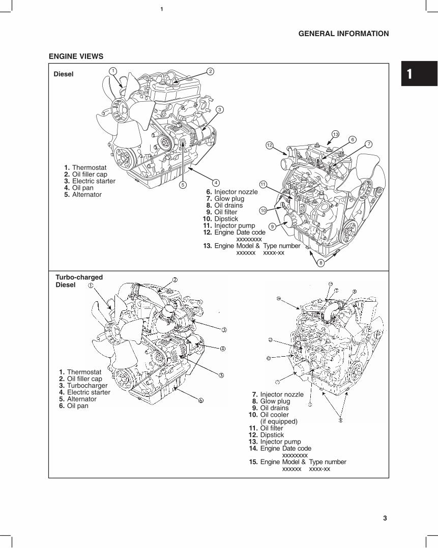
ENGINE VIEWS
1. Thermostat2. Oil filler cap3. Electric starter4. Oil pan5. Alternator
2
3
5 4
Diesel1
11
6. Injector nozzle7. Glow plug8. Oil drains9. Oil filter
10. Dipstick11. Injector pump12. Engine Date code
xxxxxxxx13. Engine Model & Type number
xxxxxx xxxx-xx
7
10
13
9
6
8
12
1. Thermostat2. Oil filler cap3. Turbocharger4. Electric starter5. Alternator6. Oil pan
Turbo-chargedDiesel
7. Injector nozzle8. Glow plug9. Oil drains
10. Oil cooler (if equipped)
11. Oil filter12. Dipstick13. Injector pump14. Engine Date code
xxxxxxxx15. Engine Model & Type number
xxxxxx xxxx-xx
1
4
GENERAL INFORMATION
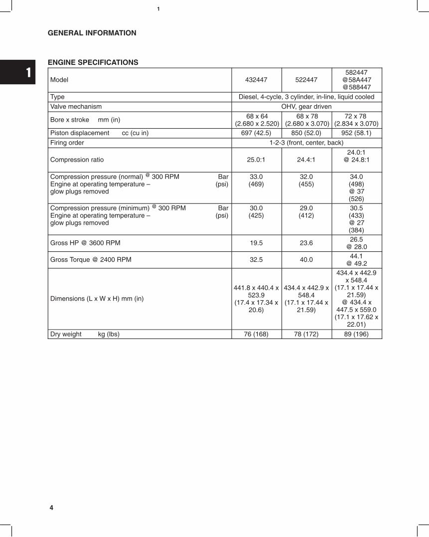
ENGINE SPECIFICATIONS
Model 432447 522447582447
@58A447@588447
Type Diesel, 4-cycle, 3 cylinder, in-line, liquid cooled
Valve mechanism OHV, gear driven
Bore x stroke mm (in) 68 x 64(2.680 x 2.520)
68 x 78(2.680 x 3.070)
72 x 78 (2.834 x 3.070)
Piston displacement cc (cu in) 697 (42.5) 850 (52.0) 952 (58.1)
Firing order 1-2-3 (front, center, back)
Compression ratio 25.0:1 24.4:124.0:1
@ 24.8:1
Compression pressure (normal) @ 300 RPM BarEngine at operating temperature (psi)glow plugs removed
33.0(469)
32.0(455)
34.0(498)@ 37(526)
Compression pressure (minimum) @ 300 RPM BarEngine at operating temperature (psi)glow plugs removed
30.0(425)
29.0(412)
30.5(433)@ 27(384)
Gross HP @ 3600 RPM 19.5 23.6 26.5@ 28.0
Gross Torque @ 2400 RPM 32.5 40.0 44.1@ 49.2
Dimensions (L x W x H) mm (in)
441.8 x 440.4 x523.9
(17.4 x 17.34 x20.6)
434.4 x 442.9 x548.4
(17.1 x 17.44 x21.59)
434.4 x 442.9x 548.4
(17.1 x 17.44 x21.59)
@ 434.4 x447.5 x 559.0(17.1 x 17.62 x
22.01)
Dry weight kg (lbs) 76 (168) 78 (172) 89 (196)

1
5
GENERAL INFORMATION
Cylinder Type Single piece castingCylinderHead Material Cast Iron
Combustion Chamber Swirl Type
Valve seat angleIntake 45°
Valve seat angleExhaust 45°
Valve IntakeOpens 10° BTDC
235°ValveSpecifications Valve timing
IntakeCloses 45° ABDC
235°Specifications Valve timing
ExhaustOpens 45° BBDC
235°ExhaustCloses 10° ATDC
235°
Valve clearance (cold)Intake mm (in) 0.20 (.008 in)
Valve clearance (cold)Exhaust mm (in) 0.20 (.008 in)
CylinderBlock &
Cylinder block Mono-block, three cylinder, cast ironBlock &Camshaft Camshaft Carbon steel
Connecting rod Carbon steelPiston Pin Bearing Machined Piston pin, slip fit
ConnectingRod & Piston
CrankpinBearing
Material aluminum alloy replaceable insertRod & Piston
Piston Heat resistant aluminum alloy
Piston ringCompression ring Two, chrome plated
Piston ringOil ring One, combination type, chrome plated
Crankshaft & Crankshaft One piece cast ironCrankshaft &CrankshaftBearing
Crankshaft mainbearing
Material Replaceable insert aluminum alloy
1
6
GENERAL INFORMATION
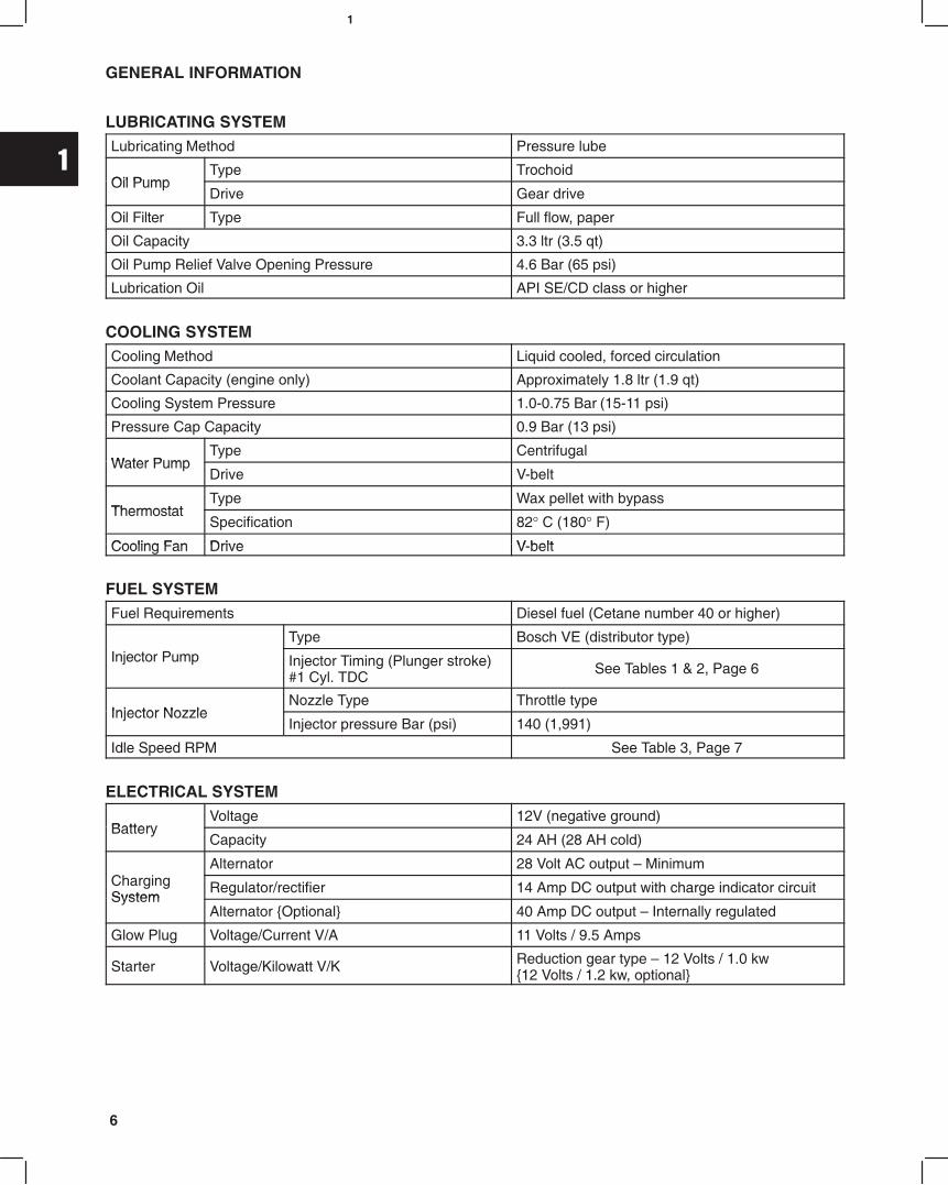
LUBRICATING SYSTEMLubricating Method Pressure lube
Oil PumpType Trochoid
Oil PumpDrive Gear drive
Oil Filter Type Full flow, paper
Oil Capacity 3.3 ltr (3.5 qt)
Oil Pump Relief Valve Opening Pressure 4.6 Bar (65 psi)
Lubrication Oil API SE/CD class or higher
COOLING SYSTEMCooling Method Liquid cooled, forced circulation
Coolant Capacity (engine only) Approximately 1.8 ltr (1.9 qt)
Cooling System Pressure 1.0-0.75 Bar (15-11 psi)
Pressure Cap Capacity 0.9 Bar (13 psi)
Water PumpType Centrifugal
Water PumpDrive V-belt
ThermostatType Wax pellet with bypass
ThermostatSpecification 82° C (180° F)
Cooling Fan Drive V beltCooling Fan Drive V-belt
FUEL SYSTEMFuel Requirements Diesel fuel (Cetane number 40 or higher)
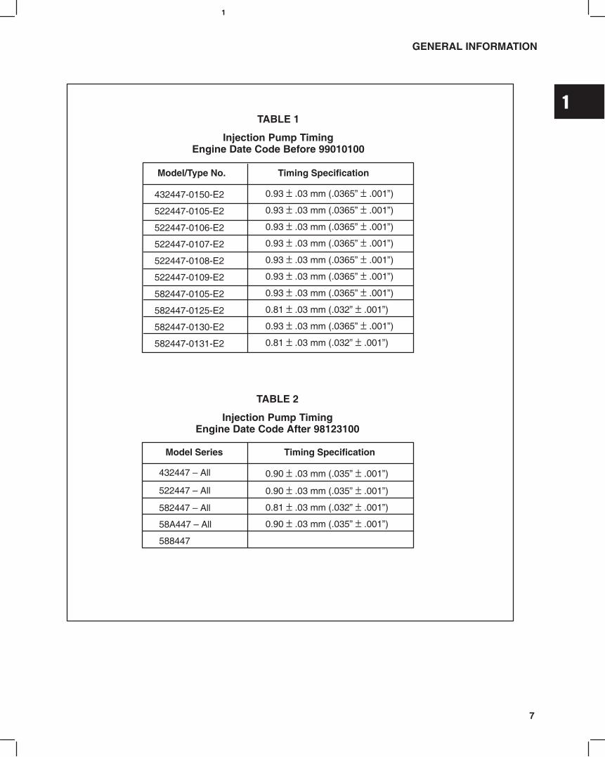
Type Bosch VE (distributor type)Injector Pump Injector Timing (Plunger stroke)
#1 Cyl. TDCSee Tables 1 & 2, Page 6
Injector NozzleNozzle Type Throttle type
Injector NozzleInjector pressure Bar (psi) 140 (1,991)
Idle Speed RPM See Table 3, Page 7
ELECTRICAL SYSTEM
BatteryVoltage 12V (negative ground)
BatteryCapacity 24 AH (28 AH cold)
Alternator 28 Volt AC output MinimumChargingSystem
Regulator/rectifier 14 Amp DC output with charge indicator circuitSystem
Alternator Optional 40 Amp DC output Internally regulated
Glow Plug Voltage/Current V/A 11 Volts / 9.5 Amps
Starter Voltage/Kilowatt V/K Reduction gear type 12 Volts / 1.0 kw 12 Volts / 1.2 kw, optional
1
7
GENERAL INFORMATION
Model/Type No. Timing Specification
0.93 ± .03 mm (.0365 ± .001)
0.93 ± .03 mm (.0365 ± .001)
0.93 ± .03 mm (.0365 ± .001)
0.93 ± .03 mm (.0365 ± .001)
0.93 ± .03 mm (.0365 ± .001)
0.93 ± .03 mm (.0365 ± .001)
0.93 ± .03 mm (.0365 ± .001)
0.81 ± .03 mm (.032 ± .001)
0.93 ± .03 mm (.0365 ± .001)
0.81 ± .03 mm (.032 ± .001)
432447-0150-E2
522447-0105-E2
522447-0106-E2
522447-0107-E2
522447-0108-E2
522447-0109-E2
582447-0105-E2
582447-0125-E2
582447-0130-E2
582447-0131-E2
TABLE 1
Injection Pump TimingEngine Date Code Before 99010100
TABLE 2
Injection Pump TimingEngine Date Code After 98123100
Model Series Timing Specification
0.90 ± .03 mm (.035 ± .001)
0.90 ± .03 mm (.035 ± .001)
0.81 ± .03 mm (.032 ± .001)
0.90 ± .03 mm (.035 ± .001)
432447 All
522447 All
582447 All
58A447 All
588447

1
8
TABLE 3Engine Speed Specification Chart
Pump Mfg. Part No. ID Code Model & Type No. Idle Speed (rpm) Top No Load (rpm)
22100-87801 7U1 432447-0105-E2 120050 385050
22100-8713 7U2 432447-0205-E2 120050 385050
582447-0105-E2
582447-0205-E2120050 385050
22100-87802 9U1
582447-0130-E2
582447-0230-E2120050 330050
22100 87802 9U1582447-0219-E2
582447-0222E2
160050 360050
582447-0221-E2 175050 360050582447-0225-E2 105050 385050
582447-0232-E2 120050 340050
582447-0125-E2 185050 342050
22100-87806 9U2 582447-0131-E2
582447-0231-E2170050 360050
22100 87807 8U1522447-0105-E2 120050 385050
22100-87807 8U1522447-0108-E2 160050 335050
22100 87809 8U2522447-0106-E2 185050 342050
22100-87809 8U2522447-0109-E2 185050 342050
22100-87810 8U3 522447-0107-E2 152550 277550
22100-87815 8U4 522447-0107-E2 154050 279050
22100-87817 8U5 5224470107E2 154050 279050
22100-87811 9U4 58A4470205E2 120050 385050
22100-87818 9U5 5884470205E2 120050 385050
5884470216E2 180050 360050
5884470230E2 160050 360050
5884470225E2 105050 385050
NAMEPLATE
IDENTIFICATIONCODE
IDENTIFICATION CODE
7 : 700 cc8 : 850 cc9 : 950 cc
DESTINATIONU : USAJ : JapanX : Except forUSA
SERIALNUMBER
INJECTOR PUMP IDENTIFICATION

1
9
GENERAL INFORMATION
Description Wrench/Socket Size Torque
Alternator Adjust. Bracket 12 mm 19.0 Nm (170 in. lbs.)
Alternator 14 Amp (to bracket) 12 mm 19.0 Nm (170 in. lbs.)
Alternator 40 Amp (to bracket) 12 mm 61.0 Nm (45 ft. lbs.)
Alternator Bracket (to block) 12 mm 19.0 Nm (170 in. lbs.)
Camshaft Gear 17 mm 41.0 Nm (30 ft. lbs.)
Camshaft Retainer 10 mm 8.0 Nm (70 in. lbs.)
Conn. Rod Nuts 12 mm 36.0 Nm (320 in. lbs.)
Crankshaft Pulley 19 mm 88.0 Nm (65 ft. lbs.)
Cyl. Head Bolts (8 mm dia.) 12 mm 34.0 Nm (25 ft. lbs.)
Cyl. Head Bolts (9 mm dia.) 13 mm 43.0 Nm (32 ft. lbs.)
Cyl. Head Bolts (10 mm dia.) 14 mm 68.0 Nm (50 ft. lbs.)
Exhaust Manifold 12 mm 19.0 Nm (170 in. lbs.)
Fan Pulley 10 mm 7.0 Nm (60 in. lbs.)
Flywheel 14 mm 47.0 Nm (35 ft. lbs.)
Fuel Delivery Lines 17 mm 25.0 Nm (220 in. lbs.)
Fuel Return Line 17 mm 27.0 Nm (20 ft. lbs.)
Glow Plug 12 mm Deep 17.0 Nm (150 in. lbs.)
Idler Gear 12 mm 25.0 Nm (220 in. lbs.)
Injector Pump (mounting) 12 mm 19.0 Nm (170 in. lbs.)
Injector Pump Drive Gear 19 mm 61.0 Nm (45 ft. lbs.)
Injector Pump Bracket 12 mm 19.0 Nm (170 in. lbs.)
Injector Nozzle 21 mm Deep 61.0 Nm (45 ft. lbs.)
Injector Pump Distributor Bolt 14 mm 17.0 Nm (150 in. lbs.)
Intake Manifold 10 mm 8.0 Nm (70 in. lbs.)
Main Bearing Screws 14 mm 58.0 Nm (43 ft. lbs.)
Oil Drain Plug 14 mm 25.0 Nm (220 in. lbs.)
Oil Pan 10 mm 8.0 Nm (70 in. lbs.)
Oil Pressure Relief Valve 19 mm 34.0 Nm (25 ft. lbs.)
Oil Pump Gear 12 mm 19.0 Nm (170 in. lbs.)
Oil Pump Pickup 10 mm 8.0 Nm (70 in. lbs.)
Rear Seal Support 10 mm 6.0 Nm (50 in. lbs.)
Rocker Arm Assy. 12 mm Deep 19.0 Nm (170 in. lbs.)
Rocker Arm Adjustment 10 mm 11.0 Nm (95 in. lbs.)
Starter 14 mm 40.0 Nm (30 ft. lbs.)
Starter Bracket 14 mm 34.0 Nm (25 ft. lbs.)
Starter Solenoid Phillips 9.0 Nm (80 in. lbs.)
Starter Motor Thru Bolts 10 mm 9.0 Nm (80 in. lbs.)
Timing Gear Case 10 mm 8.0 Nm (70 in. lbs.)
Timing Gear Cover(3 different lengths)
10 mm 8.0 Nm (70 in. lbs.)
Valve Cover 10 mm 6.0 Nm (50 in. lbs.)
Water Pump 12 mm 19.0 Nm (170 in. lbs.)
1
10
GENERAL INFORMATION
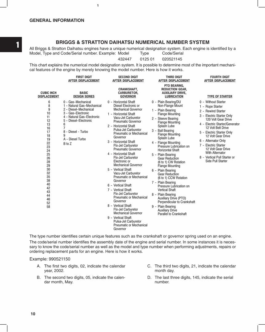
BRIGGS & STRATTON DAIHATSU NUMERICAL NUMBER SYSTEMAll Briggs & Stratton Daihatsu engines have a unique numerical designation system. Each engine is identified by aModel, Type and Code/Serial number. Example: Model Type Code/Serial
432447 0125 01 020521145This chart explains the numerical model designation system. It is possible to determine most of the important mechani-cal features of the engine by merely knowing the model number. Here is how it works.
!
"#
$%&'(
$%&')*+, -.(
$%&'-*+, -.(
$%&'/*+, -.(
$%&'/*+, (
)&')*+, -.(
)&'
)&'/*+, -.(
)&'/*+, (
)&'-*+, -.(
-"012*/0
-"0/00
&("0/00&34
""0/00&34
/00-4 $%&'
-"05678,95/00
-"05678,,95
-"0-4 )&'
-"0!:;(7-<8-36,='
-"0!:;(-,='
9&
53&
5>6&
&<;)(
&1)"(
&<;)(
!<;
&)(9!
)-&&6-&
The type number identifies certain unique features such as the crankshaft or governor spring used on an engine.The code/serial number identifies the assembly date of the engine and serial number. In some instances it is neces-sary to know the code/serial number as well as the model and type number when performing adjustments, repairs orordering replacement parts for an engine. Here is how it works.
Example: 990521150
A. The first two digits, 02, indicate the calendaryear, 2002.
B. The second two digits, 05, indicate the calen-dar month, May.
C. The third two digits, 21, indicate the calendarmonth day.
D. The last three digits, 145, indicate the serial number.
1
11
GENERAL INFORMATION
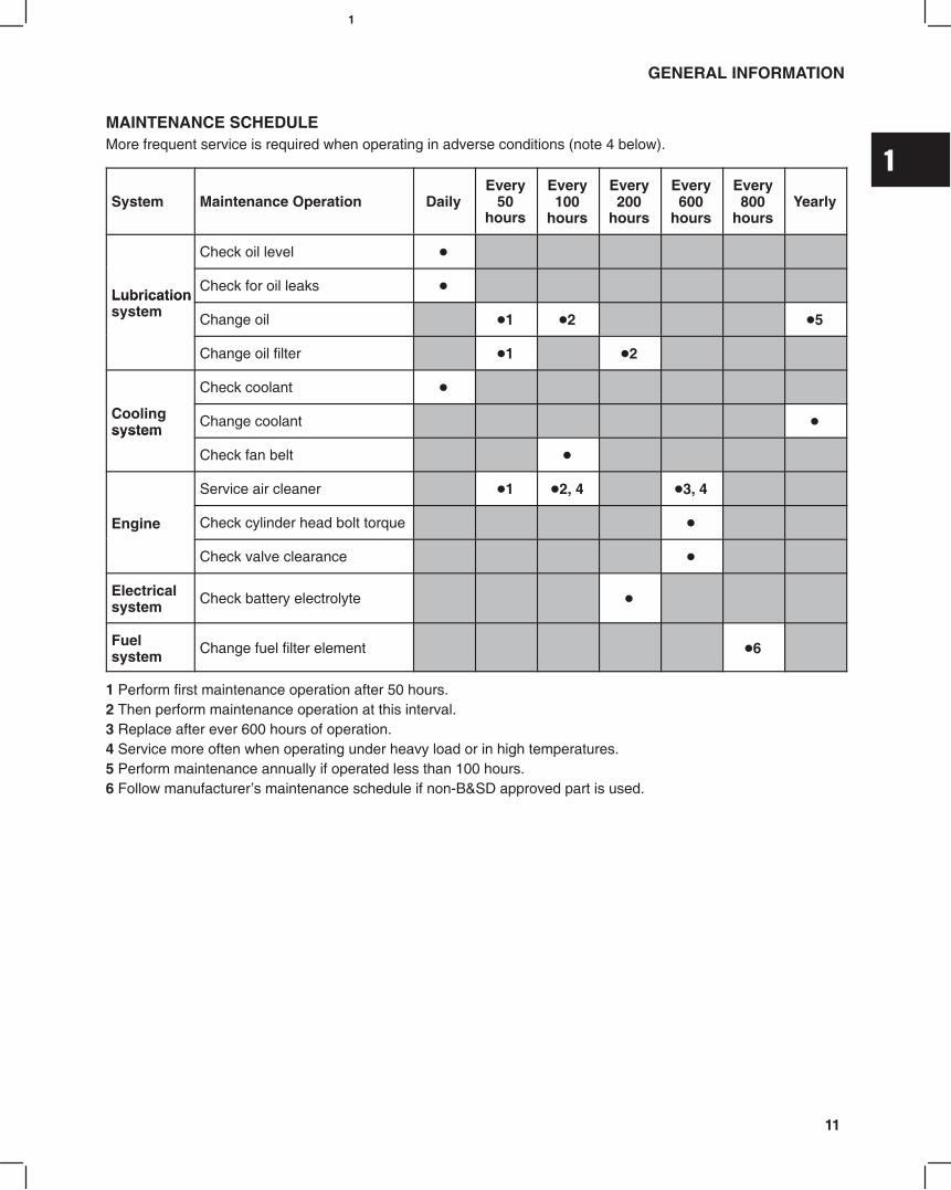
MAINTENANCE SCHEDULEMore frequent service is required when operating in adverse conditions (note 4 below).
System Maintenance Operation DailyEvery
50hours
Every100
hours
Every200
hours
Every600
hours
Every800
hoursYearly
Check oil level
LubricationCheck for oil leaks
Lubricationsystem Change oil 1 2 5
Change oil filter 1 2
Check coolant
Coolingsystem
Change coolant system
Check fan belt
Service air cleaner 1 2, 4 3, 4
Engine Check cylinder head bolt torque
Check valve clearance
Electricalsystem Check battery electrolyte
Fuelsystem Change fuel filter element 6
1 Perform first maintenance operation after 50 hours.2 Then perform maintenance operation at this interval.3 Replace after ever 600 hours of operation.4 Service more often when operating under heavy load or in high temperatures.5 Perform maintenance annually if operated less than 100 hours.6 Follow manufacturers maintenance schedule if non-B&SD approved part is used.

2
1MAY 2002
Section ContentsPage
REMOVE CYLINDER HEAD 2. . . . . . . . . . . . . . . . . . . . . . . . . . . . . . . . . . . . . . . . . . . . . . . . . . . . . . . . . . . . . .
DISASSEMBLE CYLINDER HEAD 4. . . . . . . . . . . . . . . . . . . . . . . . . . . . . . . . . . . . . . . . . . . . . . . . . . . . . . . .
INSPECT AND REPAIR
Cylinder Head 5. . . . . . . . . . . . . . . . . . . . . . . . . . . . . . . . . . . . . . . . . . . . . . . . . . . . . . . . . . . . . . . . . . . . . .
Valve Guides 6. . . . . . . . . . . . . . . . . . . . . . . . . . . . . . . . . . . . . . . . . . . . . . . . . . . . . . . . . . . . . . . . . . . . . . .
Valves 7. . . . . . . . . . . . . . . . . . . . . . . . . . . . . . . . . . . . . . . . . . . . . . . . . . . . . . . . . . . . . . . . . . . . . . . . . . . . .
DISASSEMBLE ROCKER ARM SHAFT 8. . . . . . . . . . . . . . . . . . . . . . . . . . . . . . . . . . . . . . . . . . . . . . . . . . . .
ASSEMBLE ROCKER ARM SHAFT 9. . . . . . . . . . . . . . . . . . . . . . . . . . . . . . . . . . . . . . . . . . . . . . . . . . . . . . .
ASSEMBLE CYLINDER HEAD 10. . . . . . . . . . . . . . . . . . . . . . . . . . . . . . . . . . . . . . . . . . . . . . . . . . . . . . . . . . .
INSTALL CYLINDER HEAD 11. . . . . . . . . . . . . . . . . . . . . . . . . . . . . . . . . . . . . . . . . . . . . . . . . . . . . . . . . . . . .
ADJUST VALVES 14. . . . . . . . . . . . . . . . . . . . . . . . . . . . . . . . . . . . . . . . . . . . . . . . . . . . . . . . . . . . . . . . . . . . . .
BRIGGS & STRATTON DAIHATSU 3 CYLINDERLIQUID-COOLED DIESEL ENGINE REPAIR MANUAL (MS-1055)
Section 2Cylinder Head and Valves
Overhead Valve Train

2
2
CYLINDER HEAD AND VALVES
REMOVE CYLINDER HEAD
ALWAYS disconnect fuel shut off solenoid wirefrom injection pump before checking compres-sion, to prevent accidental starting.
Drain cooling system and disconnect radiator hoses.1. Remove the following parts from engine,
Fig. 1-Fig. 5:
a. Alternator adjusting bracket screwb. V-beltc. Fan (if equipped)
Fig. 1 Remove V-belt And Fan
C
B
A
Fig. 2:d. Water pumpe. Exhaust manifoldNOTE: Remove exhaust system before removing
exhaust manifold.
Fig. 2 Remove Water Pump And Exhaust Manifold
D
E
Fig. 3:f. Valve cover
Discard rubber seal.
Fig. 3 Remove Valve Cover
F
NOTE: Clean areas around fuel lines and injec-tors to prevent dirt entry.
Fig. 4:g. Fuel delivery linesh. Fuel return linei. Glow plug wiringj. Breather tube and intake manifold
Fig. 4 Remove Fuel Lines
G
H
IJ
2
3
CYLINDER HEAD AND VALVES
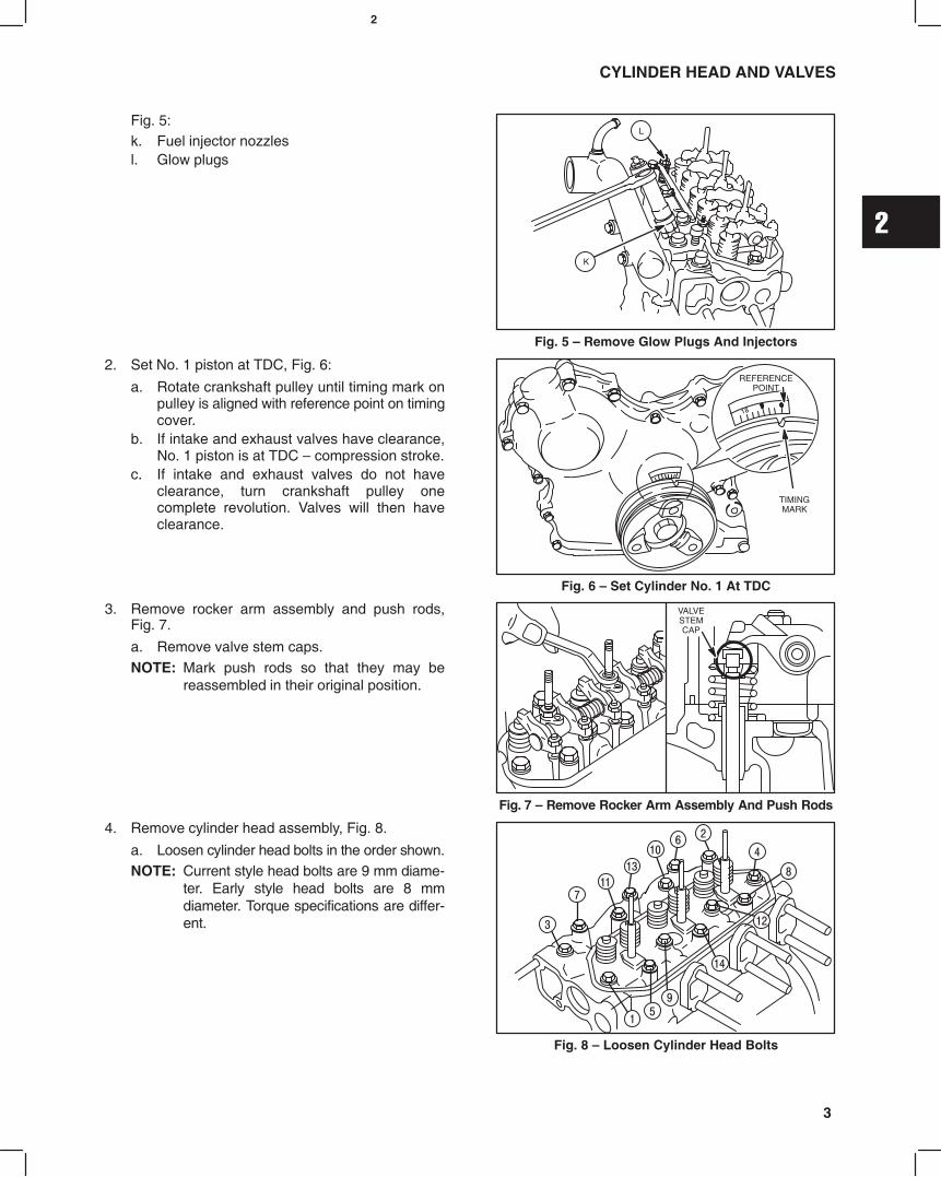
Fig. 5:k. Fuel injector nozzlesl. Glow plugs
Fig. 5 Remove Glow Plugs And Injectors
K
L
2. Set No. 1 piston at TDC, Fig. 6:
a. Rotate crankshaft pulley until timing mark onpulley is aligned with reference point on timingcover.
b. If intake and exhaust valves have clearance,No. 1 piston is at TDC compression stroke.
c. If intake and exhaust valves do not haveclearance, turn crankshaft pulley onecomplete revolution. Valves will then haveclearance.
Fig. 6 Set Cylinder No. 1 At TDC
REFERENCEPOINT
TIMINGMARK
3. Remove rocker arm assembly and push rods,Fig. 7.
a. Remove valve stem caps.NOTE: Mark push rods so that they may be
reassembled in their original position.
VALVESTEMCAP
Fig. 7 Remove Rocker Arm Assembly And Push Rods
4. Remove cylinder head assembly, Fig. 8.
a. Loosen cylinder head bolts in the order shown.NOTE: Current style head bolts are 9 mm diame-
ter. Early style head bolts are 8 mmdiameter. Torque specifications are differ-ent.
Fig. 8 Loosen Cylinder Head Bolts
2
4
CYLINDER HEAD AND VALVES
Fig. 9 Cylinder Head Components
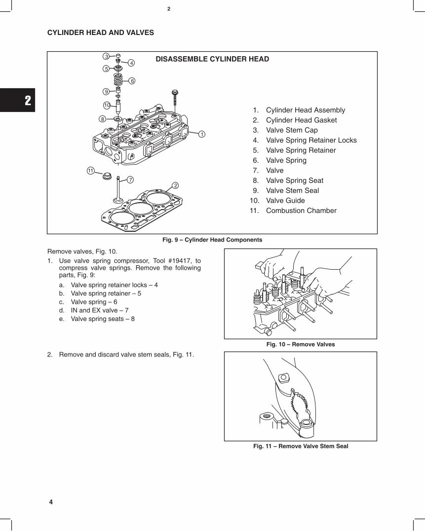
DISASSEMBLE CYLINDER HEAD
1. Cylinder Head Assembly2. Cylinder Head Gasket3. Valve Stem Cap4. Valve Spring Retainer Locks5. Valve Spring Retainer6. Valve Spring7. Valve8. Valve Spring Seat9. Valve Stem Seal
10. Valve Guide11. Combustion Chamber
34
5
6
7
1
2
8
9
10
11
Remove valves, Fig. 10.1. Use valve spring compressor, Tool #19417, to
compress valve springs. Remove the followingparts, Fig. 9:
a. Valve spring retainer locks 4b. Valve spring retainer 5c. Valve spring 6d. IN and EX valve 7e. Valve spring seats 8
Fig. 10 Remove Valves
2. Remove and discard valve stem seals, Fig. 11.
Fig. 11 Remove Valve Stem Seal

2
5
CYLINDER HEAD AND VALVES
INSPECT AND REPAIR1. Check cylinder head mounting surfaces, Fig. 12
and Fig. 13.
Be sure all gasket material is removed from surfacesbefore checking. Use a gasket scraper if necessary.
a. Inspect cylinder head for cracks or damage.b. Use a straight edge and check cylinder head
lower surface for distortion.
Fig. 12 Check Cylinder Head For Distortion
STRAIGHTEDGE
Fig. 13:c. Check intake and exhaust manifold mounting
surfaces.
If mounting surfaces are distorted more than 0.1 mm(0.004 in.), the cylinder head must be replaced.
It is not recommended that cylinder headmounting surfaces be resurfaced.
NOTE: Intake manifold and exhaust manifoldmay be checked in the same manner. Usesame specifications as cylinder head.
Fig. 13 Check Cylinder Head For Distortion
CHECK COMBUSTION CHAMBEREngine Model 522000: combustion chambers arenot replaceable.Engine Models 432000 and 582000 with date codeafter 990111007: combustion chambers are notreplaceable.
NOTE: Only Engine Models 432000 and 582000with date code before 981225006 havereplaceable combustion chambers.
1. Check combustion chamber, Fig. 14.
a. Use a straight edge and feeler gauge.
If combustion chamber protrudes more than 0.05 mm(.002 in.) above surface of cylinder head, it must bereplaced.
Fig. 14 Check Combustion Chamber
COMBUSTIONCHAMBER
COMBUSTIONCHAMBER
2. Remove combustion chamber, Fig. 15.
Insert a 10 mm brass rod through injector nozzle holeand drive out combustion chamber.
NOTE: Do not damage threads in injector hole.
Fig. 15 Remove Combustion Chamber
BRASS ROD
COMBUSTIONCHAMBER

2
6
CYLINDER HEAD AND VALVES
3. Install combustion chamber, Fig. 16.
Align locating projection on combustion chamber withgroove in cylinder head. Use a soft hammer and drivein new combustion chamber until it bottoms.
Fig. 16 Install Combustion Chamber
COMBUSTIONCHAMBER
CHECK AND REPAIR VALVE GUIDES1. Check valve guide bushings for wear using reject
gauge, Tool #19382, Fig. 17.
Remove if damaged or if reject gauge enters valveguide.
Fig. 17 Check Valve Guide Bushing
REJECTGAGE
2. Remove valve guide bushing if required, Fig. 18.
a. Use bushing driver, Tool #19367, and pressout valve guide bushing from combustionchamber side.
b. Check valve guide bushing OD. Then seespecifications below.
Std. Bushing OD: 11.05 mm (.435 in.)Replacement Bushing OD: 11.08 mm (.4362 in.)
c. If bushing OD measurement indicates that areplacement bushing has already beeninstalled, the cylinder head must be replaced.
Fig. 18 Remove Valve Guide Bushing
PRESSING OUTGUIDE

2
7
CYLINDER HEAD AND VALVES
3. Using bushing driver, Tool #19416, press in newvalve guide bushing until tool bottoms on cylinderhead, Fig. 19.
Fig. 19 Installing Valve Guide Bushing
VALVES AND SEATS1. Valve faces may be resurfaced to 45°. See Fig. 20
for dimensions for valves. Lap valves and seatswith valve lapping Tool, #19258 and valve lappingcompound, Tool #94150.
Fig. 20 Valve Dimensions
SEATING AREA CENTEREDON VALVE FACE
(1/16 TO 3/64)(.040)
MINIMUM0.8 mm TO 1.2 mm
1.0 mm
2. Valve seats may be reconditioned using valve seatcutter, Tool #19446.
NOTE: Check valve guide bushings first. If valveguides are worn, they must be replacedbefore refacing valve seats
If valve seat is wider than dimension shown in Fig. 21,a narrowing cutter should be used to ensure thatcontact area of valve seat is centered on face of valve,Fig. 20.
a. Use a 60° cutter to narrow seat from bottomand a 30° cutter to narrow seat from top,Fig. 21.
NOTE: If valve seat is loose or cracked, replacecylinder head.
Fig. 21 Valve Seat Dimensions
45°
VALVE SEAT DIMENSIONS
ÉÉÉÉ
60° CUTTER
30° CUTTER
ÉÉÉÉÉÉ
ÉÉÉÉ
ÉÉÉÉÉÉ
(1/16 TO 3/64)0.8 mm TO 1.2 mm
3. Measure valve stem diameter at specifieddistance from end of valve, as shown in Fig. 22.
Replace IN if less than 5.927 mm (0.2333 in.).
Replace EX if less than 5.923 mm (0.2332 in.).
Fig. 22 Measure Valve Stem Diameter
35 mm(1.38)

2
8
CYLINDER HEAD AND VALVES
4. Inspect valve stem cap for wear, Fig. 23.
Replace if cap is worn recessed.
Fig. 23 Check Valve Stem Cap
5. Check valve springs for squareness and freelength, Fig. 24.
Replace if out of square more than 1.0 mm(.040 in.).
Replace if free length is less than 30.7 mm(1.209 in.).
Fig. 24 Check Valve Springs
DISASSEMBLE ROCKER ARM SHAFT1. Remove snap rings from ends of rocker arm shaft. Remove set screw from center rocker arm support. Disassemble
rocker arm assembly. Note position of all components, Fig. 25.
Fig. 25 Rocker Arm Components
SETSCREW
(1)SPRING
(2) ROCKERARM(6)
SNAPRING
(2)
SPACER(3)ROCKER
ARM SUPPORT(3)
ROCKERARM
SHAFT

2
9
CYLINDER HEAD AND VALVES
2. Check rocker arms and shaft, Fig. 26.
a. Check rocker arm-bearing surface.
Replace if greater than 10.03 mm (0.395 in.).b. Check rocker arm shaft
Replace if less than 9.96 mm (0.392 in.).c. Check rocker arm studs for stripped threads
and replace if required.
Fig. 26 Checking Rocker Arm And Shaft
ASSEMBLE ROCKER ARM SHAFT1. Oil all components before assembling. Small grooves in rocker shaft next to oil holes must face down. Assemble
rocker arm components, noting order of assembly as shown in Fig. 27. Note position of three thrust washers.Install set screw in center rocker arm shaft support.
Fig. 27 Rocker Arm Components
SETSCREW
(1)SPRING
(2) ROCKERARM(6)
SNAPRING
(2)
THRUSTWASHER
(3)
ROCKERARM SUPPORT
(3)
ROCKERARM
SHAFT OILGROOVES
DOWN

2
10
CYLINDER HEAD AND VALVES
Fig. 28 Cylinder Head Components
ASSEMBLE CYLINDER HEAD 1. Cylinder Head 2. Cylinder Head Gasket3. Valve Stem Cap4. Valve Spring Retainer Locks5. Valve Spring Retainer6. Valve Spring7. Valve8. Valve Spring Seat9. Valve Stem Seal
10. Valve Guide11. Push Rod12. Rocker Arm Assembly13. Rocker Arm Stud
NOTE: When replacing rocker arm studs, torque to 20.0 Nm (180 in. lbs.).
1. Install new valve stem seals, Fig. 29. Oil innersurface and lip of seal before installing. Press sealon to valve guide bushing until it bottoms.
Fig. 29 Install Valve Stem Seals
VALVE STEMSEAL
(CUTAWAY VIEW)
2
11
CYLINDER HEAD AND VALVES
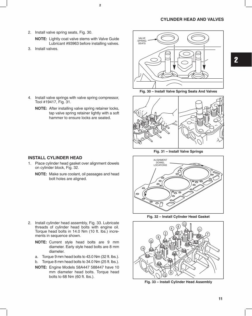
2. Install valve spring seats, Fig. 30.
NOTE: Lightly coat valve stems with Valve GuideLubricant #93963 before installing valves.
3. Install valves.
Fig. 30 Install Valve Spring Seats And Valves
VALVESPRINGSEATS
4. Install valve springs with valve spring compressor,Tool #19417, Fig. 31.
NOTE: After installing valve spring retainer locks,tap valve spring retainer lightly with a softhammer to ensure locks are seated.
Fig. 31 Install Valve Springs
INSTALL CYLINDER HEAD1. Place cylinder head gasket over alignment dowels
on cylinder block, Fig. 32.
NOTE: Make sure coolant, oil passages and headbolt holes are aligned.
Fig. 32 Install Cylinder Head Gasket
ALIGNMENTDOWEL
LOCATIONS
2. Install cylinder head assembly, Fig. 33. Lubricatethreads of cylinder head bolts with engine oil.Torque head bolts in 14.0 Nm (10 ft. lbs.) incre-ments in sequence shown.
NOTE: Current style head bolts are 9 mmdiameter. Early style head bolts are 8 mmdiameter.
a. Torque 9 mm head bolts to 43.0 Nm (32 ft. lbs.).b. Torque 8 mm head bolts to 34.0 Nm (25 ft. lbs.).NOTE: Engine Models 58A447 588447 have 10
mm diameter head bolts. Torque headbolts to 68 Nm (60 ft. lbs.).
Fig. 33 Install Cylinder Head Assembly
2
12
CYLINDER HEAD AND VALVES
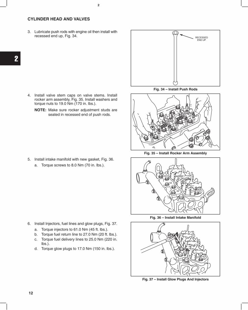
3. Lubricate push rods with engine oil then install withrecessed end up, Fig. 34.
Fig. 34 Install Push Rods
RECESSEDEND UP
4. Install valve stem caps on valve stems. Installrocker arm assembly, Fig. 35. Install washers andtorque nuts to 19.0 Nm (170 in. lbs.).
NOTE: Make sure rocker adjustment studs areseated in recessed end of push rods.
Fig. 35 Install Rocker Arm Assembly
5. Install intake manifold with new gasket, Fig. 36.
a. Torque screws to 8.0 Nm (70 in. lbs.).
Fig. 36 Install Intake Manifold
6. Install Injectors, fuel lines and glow plugs, Fig. 37.
a. Torque injectors to 61.0 Nm (45 ft. lbs.).b. Torque fuel return line to 27.0 Nm (20 ft. lbs.).c. Torque fuel delivery lines to 25.0 Nm (220 in.
lbs.).d. Torque glow plugs to 17.0 Nm (150 in. lbs.).
Fig. 37 Install Glow Plugs And Injectors
2
13
CYLINDER HEAD AND VALVES
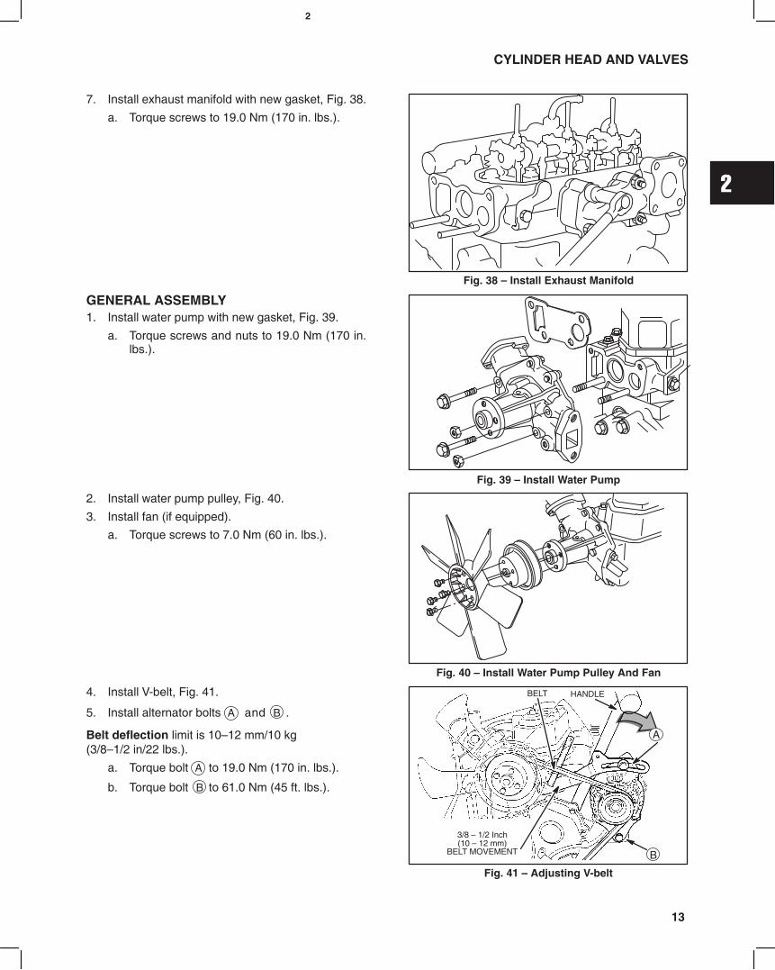
7. Install exhaust manifold with new gasket, Fig. 38.
a. Torque screws to 19.0 Nm (170 in. lbs.).
Fig. 38 Install Exhaust Manifold
GENERAL ASSEMBLY1. Install water pump with new gasket, Fig. 39.
a. Torque screws and nuts to 19.0 Nm (170 in.lbs.).
Fig. 39 Install Water Pump
2. Install water pump pulley, Fig. 40.
3. Install fan (if equipped).
a. Torque screws to 7.0 Nm (60 in. lbs.).
Fig. 40 Install Water Pump Pulley And Fan
4. Install V-belt, Fig. 41.
5. Install alternator bolts A and B .
Belt deflection limit is 1012 mm/10 kg(3/81/2 in/22 lbs.).
a. Torque bolt A to 19.0 Nm (170 in. lbs.).
b. Torque bolt B to 61.0 Nm (45 ft. lbs.).
Fig. 41 Adjusting V-belt
3/8 1/2 Inch(10 12 mm)
BELT MOVEMENT
BELT
A
B
HANDLE
2
14
CYLINDER HEAD AND VALVES
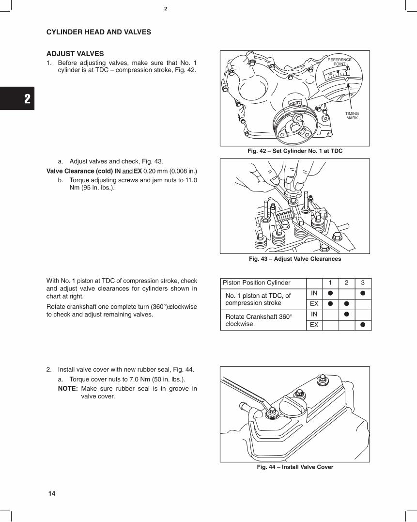
ADJUST VALVES1. Before adjusting valves, make sure that No. 1
cylinder is at TDC compression stroke, Fig. 42.
Fig. 42 Set Cylinder No. 1 at TDC
REFERENCEPOINT
TIMINGMARK
a. Adjust valves and check, Fig. 43.
Valve Clearance (cold) IN and EX 0.20 mm (0.008 in.)b. Torque adjusting screws and jam nuts to 11.0
Nm (95 in. lbs.).
Fig. 43 Adjust Valve Clearances
With No. 1 piston at TDC of compression stroke, checkand adjust valve clearances for cylinders shown inchart at right.
Rotate crankshaft one complete turn (360°)"clockwiseto check and adjust remaining valves.
Piston Position Cylinder 1 2 3
No. 1 piston at TDC, of IN No. 1 piston at TDC, ofcompression stroke EX
Rotate Crankshaft 360° IN Rotate Crankshaft 360clockwise EX
2. Install valve cover with new rubber seal, Fig. 44.
a. Torque cover nuts to 7.0 Nm (50 in. lbs.).NOTE: Make sure rubber seal is in groove in
valve cover.
Fig. 44 Install Valve Cover

3
1MAY 2002
BRIGGS & STRATTON DAIHATSU 3 CYLINDER
LIQUID-COOLED DIESEL ENGINE REPAIR MANUAL (MS-1055)
Section 3Timing Gears and Gear Case
Section ContentsPage
REMOVE TIMING GEAR COVER AND GEARS 2. . . . . . . . . . . . . . . . . . . . . . . . . . . . . . . . . . . . . . . . . . . . . . . . . . . . . .
CHECKING GEARS 3. . . . . . . . . . . . . . . . . . . . . . . . . . . . . . . . . . . . . . . . . . . . . . . . . . . . . . . . . . . . . . . . . . . . . . . . . . . . . .
REMOVE GEAR CASE 4. . . . . . . . . . . . . . . . . . . . . . . . . . . . . . . . . . . . . . . . . . . . . . . . . . . . . . . . . . . . . . . . . . . . . . . . . . .
REPLACE TIMING GEAR COVER OIL SEAL 5. . . . . . . . . . . . . . . . . . . . . . . . . . . . . . . . . . . . . . . . . . . . . . . . . . . . . . . .
ASSEMBLE TIMING GEAR CASE AND GEARS 5. . . . . . . . . . . . . . . . . . . . . . . . . . . . . . . . . . . . . . . . . . . . . . . . . . . . . .

3
2
TIMING GEARS AND GEAR CASE
REMOVING TIMING GEAR COVER AND GEARS
Make sure that #1 cylinder is at TDC, compressionstroke. See Section 2, Fig. 6.Remove V-belt and fan (if equipped). Drain oil fromengine.
NOTE: Clean areas around fuel lines and injec-tors to prevent dirt entry.
1. Remove the following parts, Fig. 1.a. Glow plug wiring.b. Glow plugs.c. Injector pump bracket.d. Remove fuel delivery lines.
Fig. 1 Remove Fuel Delivery Lines
B
A
C
D
2. Remove the following parts, Fig. 2.a. Remove oil pan and discard gasket.b. Remove oil pick-up tube and strainer. Discard
gasket.
Fig. 2 Removing Oil Pan
OIL PICK-UPTUBE
3. Remove bell housing adapter screw if equipped.and install flywheel holder, Tool #19418.
4. LEAVE TOOL INSTALLED.a. Remove crankshaft pulley using Tool
# 19420, Fig. 3.
Fig. 3 Removing Crankshaft Pulley
FLYWHEELHOLDER
5. Remove timing gear cover, Fig. 4.a. Discard timing gear cover gasket.
Fig. 4 Removing Timing Gear Cover
3
3
TIMING GEARS AND GEAR CASE
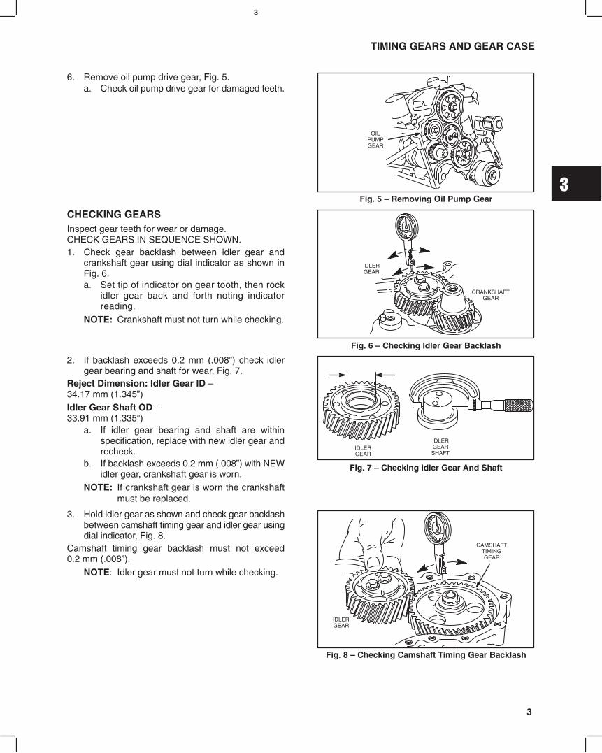
6. Remove oil pump drive gear, Fig. 5.a. Check oil pump drive gear for damaged teeth.
Fig. 5 Removing Oil Pump Gear
OILPUMPGEAR
CHECKING GEARSInspect gear teeth for wear or damage. CHECK GEARS IN SEQUENCE SHOWN.1. Check gear backlash between idler gear and
crankshaft gear using dial indicator as shown inFig. 6.a. Set tip of indicator on gear tooth, then rock
idler gear back and forth noting indicatorreading.
NOTE: Crankshaft must not turn while checking.
Fig. 6 Checking Idler Gear Backlash
IDLERGEAR
CRANKSHAFTGEAR
2. If backlash exceeds 0.2 mm (.008) check idlergear bearing and shaft for wear, Fig. 7.
Reject Dimension: Idler Gear ID 34.17 mm (1.345)Idler Gear Shaft OD 33.91 mm (1.335)
a. If idler gear bearing and shaft are withinspecification, replace with new idler gear andrecheck.
b. If backlash exceeds 0.2 mm (.008) with NEWidler gear, crankshaft gear is worn.
NOTE: If crankshaft gear is worn the crankshaftmust be replaced.
Fig. 7 Checking Idler Gear And Shaft
IDLERGEAR
IDLERGEARSHAFT
3. Hold idler gear as shown and check gear backlashbetween camshaft timing gear and idler gear usingdial indicator, Fig. 8.
Camshaft timing gear backlash must not exceed0.2 mm (.008).
NOTE: Idler gear must not turn while checking.
Fig. 8 Checking Camshaft Timing Gear Backlash
CAMSHAFTTIMINGGEAR
IDLERGEAR

3
4
TIMING GEARS AND GEAR CASE
4. Hold idler gear as shown and check gear backlashbetween injector pump timing gear and idler gearusing dial indicator, Fig. 9.
Injector pump timing gear backlash must not exceed0.2 mm (.008).
NOTE: Idler gear must not turn while checking.
If gears are worn it is recommended that they bereplaced as a set.
Fig. 9 Checking Injector Pump Timing Gear Backlash
REMOVE GEAR CASE1. Remove injector pump timing gear with a three jaw
puller, Fig. 10.a. Remove 2 nuts and injector pump. Discard
O-ring.
Fig. 10 Removing Injector Pump
O-RING
2. Remove parts in sequence shown, Fig. 11.a. Remove 3 screws and camshaft retainer.b. Remove remaining 5 screws.
Fig. 11 Removing Timing Gear Case
AB
B
3. Remove timing gear case and discard gasket,Fig. 12.a. Remove oil pump rotor from cylinder block.
Fig. 12 Remove Timing Gear Case
ROTOR

3
5
TIMING GEARS AND GEAR CASE
REPLACE TIMING GEAR COVER OIL SEAL1. Drive out oil seal.2. Use seal driver, Tool #19423, to install new oil seal,
Fig. 13.
Fig. 13 Replacing Oil Seal
ASSEMBLE TIMING GEARCASE AND GEARS1. Clean and lubricate oil pump rotor with engine oil
and install in cylinder block, Fig. 14.a. ID mark on rotor must face cylinder block.
Fig. 14 Installing Oil Pump Rotor
OIL PUMP ROTOR
ID MARK
2. Install timing gear case with new gasket. Installcamshaft retainer, Fig. 15.NOTE: It may be necessary to rotate oil pump
drive to engage oil pump rotors.
NOTE: Position camshaft retainer so that centerhole does not interfere with camshaft.
Note position, length and number of screws as shown.a. M6 x 28 mm (M6 x 1.1): 4b. M6 x 18 mm (M6 x 0.7): 3c. M6 x 16 mm (M6 x 0.6): 1
Torque screws to 8.0 Nm (70 in. lbs.).
Fig. 15 Installing Timing Gear Case
B
A
C
A
3. Assemble injector pump to gear case with newO-ring and install nuts and support bracket screwfinger tight, Fig. 16.NOTE: Pump must be able to rotate.a. Align timing mark on injector pump with timing
mark on gear case.NOTE: See Section 10 for injector pump tim-
ing procedure.
Fig. 16 Install Injector Pump
TIMINGMARKS

3
6
TIMING GEARS AND GEAR CASE
4. Assemble idler gear shaft with arrow up, as shownin Fig. 17.
Fig. 17 Installing Idler Gear Shaft
ARROWUP
Engine models 432000 and 582000 after date code990111007, and all engine models 522000 areequipped with right angle helical timing gears. Timingmarks are identified by letters (A, AA, B, BB, etc.),instead of numbers. The timing procedure is the same.5. With crankshaft key at 12 oclock position,
assemble idler gear so that timing mark 11 (AA) isaligned with timing mark 1 (A) on crankshaft gear,timing mark 22 (BB) is aligned with timing mark 2(B) on camshaft gear, and timing mark 33 (CC) isaligned with timing mark 3 (C) on injector pumpgear, as shown in Fig. 18.a. Install oil pump gear.
Fig. 18 Aligning Timing Marks Typical
CRANKSHAFTKEY
12 OCLOCK
6. Torque screws as shown, Fig. 19.a. Camshaft Gear: 41.0 Nm (30 ft. lbs.)b. Idler Gear: 25.0 Nm (220 in. lbs.)c. Injector Pump Gear: 61.0 Nm (45 ft. lbs.)d. Oil Pump Gear: 19.0 Nm (170 in. lbs.)
Fig. 19 Torque Screws
C
D
B
A
7. Install timing gear cover with new gasket. Noteposition, length and number of screws as shown,Fig. 20.a. M6 x 55 mm (M6 x 2.5): 3b. M6 x 45 mm (M6 x 2.1): 2c. M6 x 30 mm (M6 x 1.1): 9d. M6 nut: 2
Torque screws and nuts to 8.0 Nm (70 in. lbs.).
Fig. 20 Installing Timing Gear Cover
B
CA
A
B DCD
C
C

3
7
TIMING GEARS AND GEAR CASE
8. Install crankshaft pulley with timing mark at12 oclock position (#1 cylinder), Fig. 21.NOTE: Be sure alignment pin in crankshaft gear
is seated in hole in pulley.a. Torque screw to 88.0 Nm (65 ft. lbs.).b. Remove flywheel holder.
Fig. 21 Installing Crankshaft Pulley
9. Install oil pick-up tube and strainer with newgasket. Torque to 8.0 Nm (70 in. lbs.).a. Apply a small bead of Permatex No. 2 or
similar sealant to crankcase areas shown,Fig. 22.
b. Install oil pan with new gasket.c. Torque screws and nuts to 8.0 Nm
(70 in. lbs.).
Fig. 22 Installing Oil Pan
SEALANT
10. Install glow plugs, wiring and fuel delivery lines.a. Torque glow plugs to 17.0 Nm (150 in. lbs.).b. Torque fuel delivery lines to 25.0 Nm
(220 in. lbs.), Fig. 23.11. Install V-belt and fan (if equipped).
Fig. 23 Installing Fuel Delivery Lines

4
1MAY 2002
BRIGGS & STRATTON DAIHATSU 3 CYLINDERLIQUID-COOLED DIESEL ENGINE REPAIR MANUAL (MS-1055)
Section 4Flywheel and Rear Seal Retainer
Section ContentsPage
REMOVING OIL PAN AND FLYWHEEL 1. . . . . . . . . . . . . . . . . . . . . . . . . . . . . . . . . . . . . . . . . . . . . . . . . . . . . . . . . . . . .
REMOVING REAR SEAL RETAINER 2. . . . . . . . . . . . . . . . . . . . . . . . . . . . . . . . . . . . . . . . . . . . . . . . . . . . . . . . . . . . . . .
REPLACING OIL SEAL 2. . . . . . . . . . . . . . . . . . . . . . . . . . . . . . . . . . . . . . . . . . . . . . . . . . . . . . . . . . . . . . . . . . . . . . . . . . .
INSTALLING REAR SEAL RETAINER AND FLYWHEEL 2. . . . . . . . . . . . . . . . . . . . . . . . . . . . . . . . . . . . . . . . . . . . . . .
INSTALL OIL PAN 3. . . . . . . . . . . . . . . . . . . . . . . . . . . . . . . . . . . . . . . . . . . . . . . . . . . . . . . . . . . . . . . . . . . . . . . . . . . . . . . .
REMOVING PAN AND FLYWHEELDrain oil from engine.1. Remove oil pan screws and nuts. Remove oil pan
and discard gasket Fig. 1.
Fig. 1 Removing Oil Pan
2. Install flywheel holder, Tool #19418
a. Remove flywheel screws and flywheel, Fig. 2.
Inspect flywheel for cracks or damage. Inspectflywheel ring gear for worn, chipped or cracked teeth.
If ring gear is worn or damaged the flywheel must bereplaced.
Fig. 2 Removing Flywheel
FLYWHEEL HOLDER

4
2
FLYWHEEL AND REAR SEAL RETAINER
REMOVE REAR SEAL RETAINERRemove rear seal retainer and discard gasket, Fig. 3.
Fig. 3 Removing Seal Retainer
REPLACING OIL SEAL1. Remove oil seal, Fig. 4.
Fig. 4 Removing Oil Seal
2. Lubricate outside diameter of oil seal.
a. Using seal driver, Tool #19424 install new oilseal, Fig. 5.
Fig. 5 Installing Oil Seal
INSTALLING REAR SEAL RETAINER ANDFLYWHEEL1. Install rear seal retainer with new gasket, Fig. 6.
a. Torque screws to 6.0 Nm (50 in. lbs.).
Fig. 6 Installing Seal Retainer
GASKET
RETAINER

4
3
FLYWHEEL AND REAR SEAL RETAINER
2. Install flywheel, Fig. 7.
NOTE: Apply Permatex No. 2 or similar sealantto flywheel screws.
a. Torque flywheel screws to 47.0 Nm (35 ft. lbs.).
Remove flywheel holder.
Fig. 7 Installing Flywheel
INSTALL OIL PAN1. Install oil pan with new gasket, Fig. 8.
a. Apply a small bead of Permatex No. 2 orsimilar sealant to crankcase areas shown.
b. Torque screws and nuts to 8.0 Nm(70 in. lbs.).
Fig. 8 Installing Oil Pan
SEALANT

5
1MAY 2002
BRIGGS & STRATTON DAIHATSU 3 CYLINDERLIQUID-COOLED DIESEL ENGINE REPAIR MANUAL (MS-1055)
Section 5Cylinder Block Disassembly
Section ContentsPage
ENGINE STAND FIXTURE 2. . . . . . . . . . . . . . . . . . . . . . . . . . . . . . . . . . . . . . . . . . . . . . . . . . . . . . . . . . . . . . . . . . . . . . . .
CYLINDER BLOCK DISASSEMBLY 3. . . . . . . . . . . . . . . . . . . . . . . . . . . . . . . . . . . . . . . . . . . . . . . . . . . . . . . . . . . . . . . . .

5
2
CYLINDER BLOCK DISASSEMBLY
ENGINE STANDAn automotive type engine stand is recommended when complete engine disassembly is required. See drawingsbelow for dimensions to make an engine stand mounting fixture. The engine stand shown below is manufactured bySnap-On.
65 mm80 mm
45 mm 39 mm
60 mm
107 mm
57 mm
45 mm
50 mm
65 mm
215 mm
8-3/8HOLES
Engine Stand Fixture
Mounting Plate
1-1/2 DIA.
1/2 THICK
13 1-1/2
5/8
2 THRUHOLES13/32
THRU HOLE21/32
5
3
CYLINDER BLOCK DISASSEMBLY
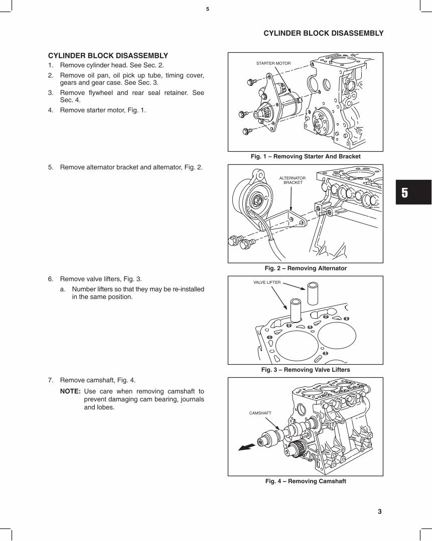
CYLINDER BLOCK DISASSEMBLY1. Remove cylinder head. See Sec. 2.
2. Remove oil pan, oil pick up tube, timing cover,gears and gear case. See Sec. 3.
3. Remove flywheel and rear seal retainer. SeeSec. 4.
4. Remove starter motor, Fig. 1.
Fig. 1 Removing Starter And Bracket
STARTER MOTOR
5. Remove alternator bracket and alternator, Fig. 2.
Fig. 2 Removing Alternator
ALTERNATOR BRACKET
6. Remove valve lifters, Fig. 3.
a. Number lifters so that they may be re-installedin the same position.
Fig. 3 Removing Valve Lifters
VALVE LIFTER
7. Remove camshaft, Fig. 4.
NOTE: Use care when removing camshaft toprevent damaging cam bearing, journalsand lobes.
Fig. 4 Removing Camshaft
CAMSHAFT
5
4
CYLINDER BLOCK DISASSEMBLY
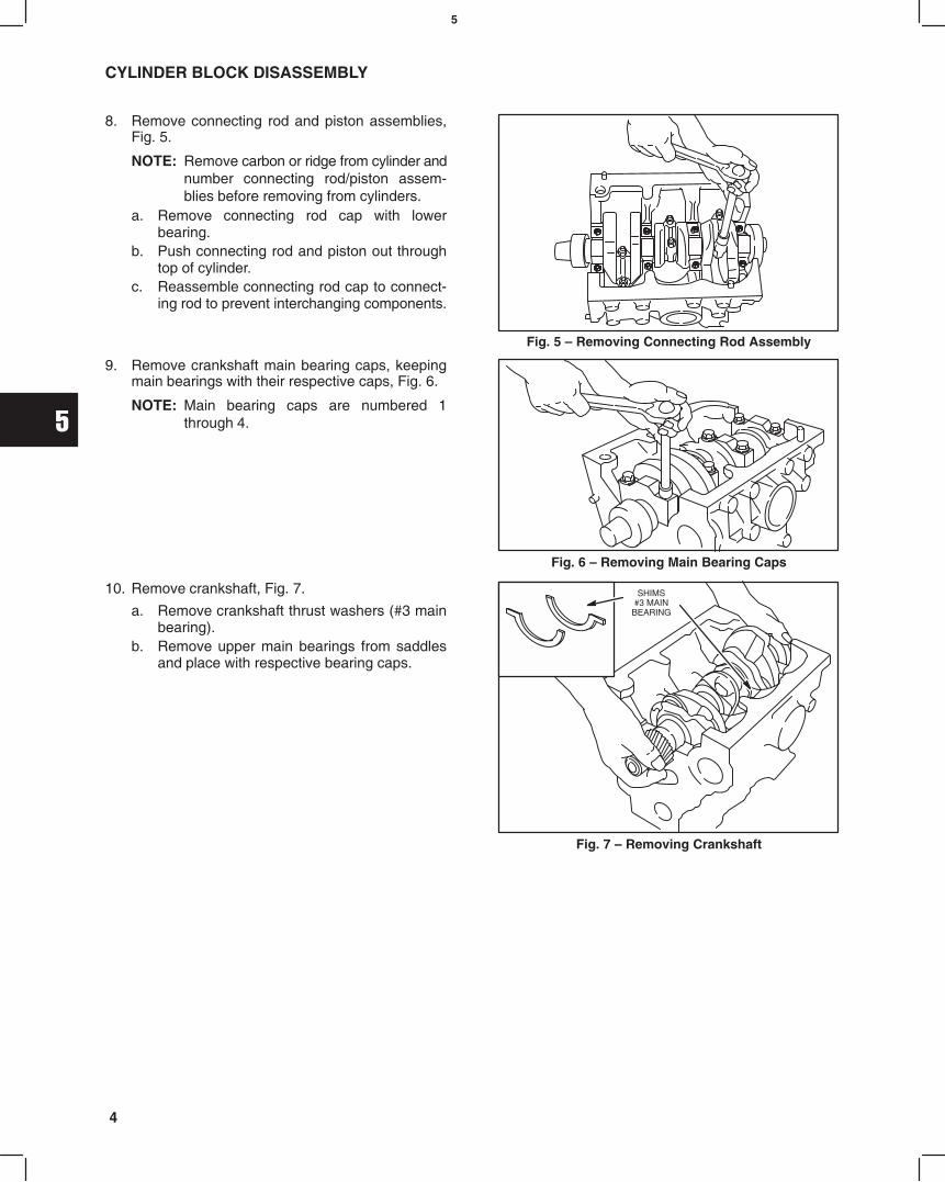
8. Remove connecting rod and piston assemblies,Fig. 5.
NOTE: Remove carbon or ridge from cylinder andnumber connecting rod/piston assem-blies before removing from cylinders.
a. Remove connecting rod cap with lowerbearing.
b. Push connecting rod and piston out throughtop of cylinder.
c. Reassemble connecting rod cap to connect-ing rod to prevent interchanging components.
Fig. 5 Removing Connecting Rod Assembly
9. Remove crankshaft main bearing caps, keepingmain bearings with their respective caps, Fig. 6.
NOTE: Main bearing caps are numbered 1through 4.
Fig. 6 Removing Main Bearing Caps
10. Remove crankshaft, Fig. 7.
a. Remove crankshaft thrust washers (#3 mainbearing).
b. Remove upper main bearings from saddlesand place with respective bearing caps.
Fig. 7 Removing Crankshaft
SHIMS#3 MAIN
BEARING

6
1MAY 2002
BRIGGS & STRATTON DAIHATSU 3 CYLINDERLIQUID-COOLED DIESEL ENGINE REPAIR MANUAL (MS-1055)
Section 6Cylinder Block Inspection and Repair
Section ContentsPage
CHECKING CYLINDER BLOCK 1. . . . . . . . . . . . . . . . . . . . . . . . . . . . . . . . . . . . . . . . . . . . . . . . . . . . . . . . . . . . . . . . . . . .
REPLACING CAMSHAFT BEARING 2. . . . . . . . . . . . . . . . . . . . . . . . . . . . . . . . . . . . . . . . . . . . . . . . . . . . . . . . . . . . . . . .
REPLACING CAMSHAFT PLUG 3. . . . . . . . . . . . . . . . . . . . . . . . . . . . . . . . . . . . . . . . . . . . . . . . . . . . . . . . . . . . . . . . . . .
CHECKING CYLINDER BLOCKRemove all traces of sealant and gasket material frommounting surfaces. Inspect cylinder block for damage,cracks and stripped threads. Inspect cylinder bores fordamage or scores.1. Check cylinder block deck for distortion, Fig. 1.
Distortion Limit: 0.08 mm (.003)
Fig. 1 Checking Cylinder Block
2. If cylinder block exceeds limit shown, it may beresurfaced, Fig. 2.
Cylinder Block Height
Model Series 430000Std: 229.20-229.80 mm (9.023-9.047)
Minimum Dimension: 229.10 mm (9.019) (After Resurfacing)
Model Series 520000 & 580000 Std: 238.70-239.30 mm (9.397-9.421)
Minimum Dimension:238.60 mm (9.3937) (After Resurfacing)
Fig. 2 Cylinder Block Height

6
2
CYLINDER BLOCK INSPECTION AND REPAIR
3. Check cylinder bores for wear, Fig. 3.
Standard Bore Size:Model Series 430000 & 520000:
68.00-68.030 mm (2.6770-2.6783)Model Series 580000:
72.00-72.030 mm (2.8346-2.8358)a. Measure cylinder bore in 6 points at right
angles as shown, Fig. 3.b. If cylinder bore is worn more than 0.075 mm
(.003) or more than 0.035 mm (.0015) out ofround, it must be resized.
Always resize to exactly .25 mm (.010) over standardbore size. If this is done accurately, the serviceoversize rings and pistons will fit perfectly and properclearances will be maintained.
Fig. 3 Checking Cylinder Bore
MEASURE CYLINDERBORE IN SIXPOSITIONS SHOWNTO DETERMINETAPER & OUT OFROUND.
AREA OFNORMAL
WEAR
TOP OF RING TRAVEL(BELOW RIDGE)
CENTER OF RING TRAVEL
BOTTOM OF RING TRAVEL
4. Check valve lifter bore, Fig. 4.
Std. Dimension: 18.018 mm (.7094)Reject: 18.05 mm (.711)
5. Check valve lifter, Fig. 4.
Std. Dimension: 17.98 mm (.708)Reject: 17.91 mm (.7051)
Fig. 4 Checking Valve Lifter And Bore
6. Check camshaft bearing, Fig. 5.
Replace if greater than 36.06 mm (1.420).
Fig. 5 Checking Cam Bearing
REPLACING CAMSHAFT BEARING1. Remove camshaft bearing, Fig. 6.
a. Use camshaft bearing puller, Tool #19421.
Fig. 6 Removing Cam Bearing
6
3
CYLINDER BLOCK INSPECTION AND REPAIR
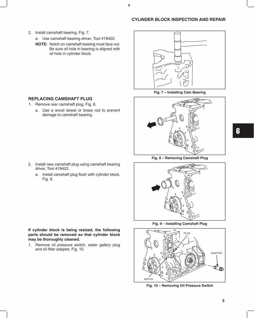
2. Install camshaft bearing, Fig. 7.
a. Use camshaft bearing driver, Tool #19422.NOTE: Notch on camshaft bearing must face out.
Be sure oil hole in bearing is aligned withoil hole in cylinder block.
Fig. 7 Installing Cam Bearing
REPLACING CAMSHAFT PLUG1. Remove rear camshaft plug, Fig. 8.
a. Use a wood dowel or brass rod to preventdamage to camshaft bearing.
Fig. 8 Removing Camshaft Plug
2. Install new camshaft plug using camshaft bearingdriver, Tool #19422.
a. Install camshaft plug flush with cylinder block,Fig. 9.
Fig. 9 Installing Camshaft Plug
If cylinder block is being resized, the followingparts should be removed so that cylinder blockmay be thoroughly cleaned.1. Remove oil pressure switch, water gallery plug
and oil filter adapter, Fig. 10.
Fig. 10 Removing Oil Pressure Switch
ADAPTER
PLUG
SWITCH

6
4
CYLINDER BLOCK INSPECTION AND REPAIR
2. Remove timing gear oil nozzle, Fig. 11.
Fig. 11 Removing Oil Nozzle
OIL NOZZLE
3. When re-installing oil nozzle, oil hole must bepositioned at 45°"angle, pointing towards idlergear, Fig. 12.
Fig. 12 Installing Oil Nozzle
IDLER GEAR
7
1MAY 2002
Section 7Crankshaft, Camshaft and Bearings
Section Contents
Page
CHECKING CRANKSHAFT 1. . . . . . . . . . . . . . . . . . . . . . . . . . . . . . . . . . . . . . . . . . . . . . . . . . . . . . . . . . . . . .
CHECKING MAIN BEARING CLEARANCES 2. . . . . . . . . . . . . . . . . . . . . . . . . . . . . . . . . . . . . . . . . . . . . . .
CHECKING CONNECTING ROD BEARING CLEARANCES 3. . . . . . . . . . . . . . . . . . . . . . . . . . . . . . . . . .
CHECKING CRANKSHAFT END PLAY 3. . . . . . . . . . . . . . . . . . . . . . . . . . . . . . . . . . . . . . . . . . . . . . . . . . . .
CHECKING CAMSHAFT 4. . . . . . . . . . . . . . . . . . . . . . . . . . . . . . . . . . . . . . . . . . . . . . . . . . . . . . . . . . . . . . . . .
BRIGGS & STRATTON DAIHATSU 3 CYLINDERLIQUID-COOLED DIESEL ENGINE REPAIR MANUAL (MS-1055)
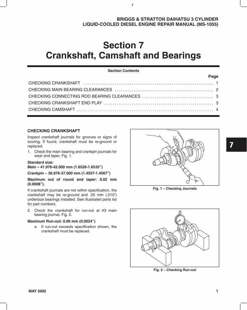
CHECKING CRANKSHAFTInspect crankshaft journals for grooves or signs ofscoring. If found, crankshaft must be re-ground orreplaced.1. Check the main bearing and crankpin journals for
wear and taper, Fig. 1.
Standard size: Main 41.976-42.000 mm (1.6526-1.6535)
Crankpin 36.976-37.000 mm (1.4557-1.4567)
Maximum out of round and taper: 0.02 mm(0.0008).
If crankshaft journals are not within specification, thecrankshaft may be re-ground and .25 mm (.010)undersize bearings installed. See illustrated parts listfor part numbers.
Fig. 1 Checking Journals
2. Check the crankshaft for run-out at #3 mainbearing journal, Fig. 2.
Maximum Run-out: 0.06 mm (0.0024)a. If run-out exceeds specification shown, the
crankshaft must be replaced.
Fig. 2 Checking Run-out
7
2
CRANKSHAFT, CAMSHAFT AND BEARINGS
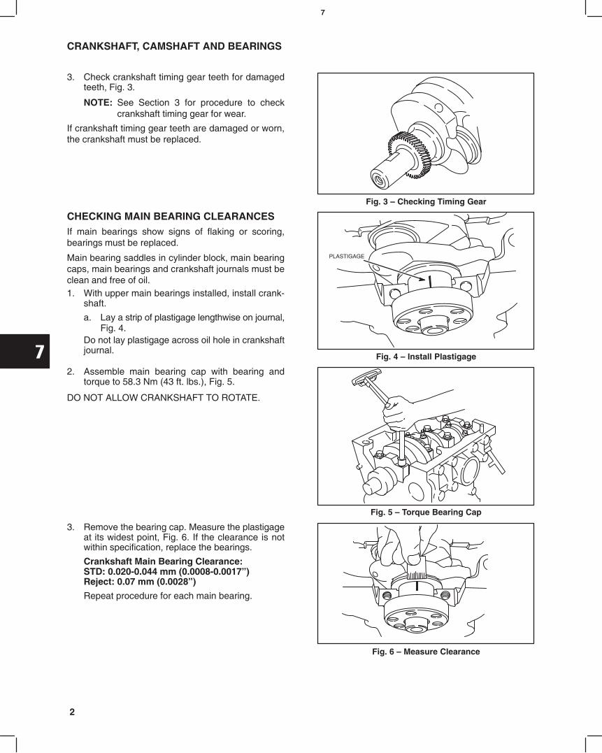
3. Check crankshaft timing gear teeth for damagedteeth, Fig. 3.
NOTE: See Section 3 for procedure to checkcrankshaft timing gear for wear.
If crankshaft timing gear teeth are damaged or worn,the crankshaft must be replaced.
Fig. 3 Checking Timing Gear
CHECKING MAIN BEARING CLEARANCESIf main bearings show signs of flaking or scoring,bearings must be replaced.
Main bearing saddles in cylinder block, main bearingcaps, main bearings and crankshaft journals must beclean and free of oil.1. With upper main bearings installed, install crank-
shaft.
a. Lay a strip of plastigage lengthwise on journal,Fig. 4.
Do not lay plastigage across oil hole in crankshaftjournal.
Fig. 4 Install Plastigage
PLASTIGAGE
2. Assemble main bearing cap with bearing andtorque to 58.3 Nm (43 ft. lbs.), Fig. 5.
DO NOT ALLOW CRANKSHAFT TO ROTATE.
Fig. 5 Torque Bearing Cap
3. Remove the bearing cap. Measure the plastigageat its widest point, Fig. 6. If the clearance is notwithin specification, replace the bearings.
Crankshaft Main Bearing Clearance:STD: 0.020-0.044 mm (0.0008-0.0017)Reject: 0.07 mm (0.0028)
Repeat procedure for each main bearing.
Fig. 6 Measure Clearance

7
3
CRANKSHAFT, CAMSHAFT AND BEARINGS
CHECKING CONNECTING ROD BEARINGCLEARANCESIf connecting rod bearings show signs of flaking orscoring, bearings must be replaced.
Connecting rod bearings and crankpin journals mustbe clean and free of oil.1. With upper bearing assembled to connecting rod,
install connecting rod.
a. Lay a strip of plastigage lengthwise on journal,Fig. 7.
Do not lay plastigage across oil hole in crankpinjournal. Fig. 7 Install Plastigage
PLASTIGAGE
2. Assemble connecting rod cap with bearing andtorque to 36.0 Nm (320 in. lbs.), Fig. 8.
DO NOT ALLOW CRANKSHAFT TO ROTATE.
Fig. 8 Torque Rod Cap
3. Remove the connecting rod cap. Measure theplastigage at its widest point, Fig. 9. If theclearance is not within specification, replace thebearings.
Connecting Rod Bearing Clearance:STD: 0.020-0.044 mm (0.0008-0.0017)Reject: 0.07 mm (0.0028)
Repeat procedure for each connecting rod.
Fig. 9 Measure Clearance
CHECKING CRANKSHAFT END PLAYWith thrust washers installed, check crankshaft endplay at #3 main bearing as shown, Fig. 10.
Crankshaft End Play:STD: 0.020-0.24 mm (0.0008-0.0094)Limit: 0.30 mm (0.012)
If end play exceeds limit, .125 mm (.005) over sizethrust washers are available. See illustrated parts list.
Fig. 10 Checking Crankshaft End Play

7
4
CRANKSHAFT, CAMSHAFT AND BEARINGS
CHECKING CAMSHAFT1. Measure camshaft lobe height, Fig. 11. If lobes are
not to specification, replace the camshaft.
Intake and Exhaust:STD: 30.065-30.135 mm (1.184-1.186)Reject: 29.965 mm (1.18)
Fig. 11 Checking Camshaft Lobes
2. Measure camshaft journals, Fig. 12.
STD: Front 35.959-35.975 mm(1.4157-1.4163)
Reject: 35.890 mm (1.413)
STD: Center 35.910-35.955 mm(1.4138-1.4155)
Reject: 35.84 mm (1.411)
STD: Rear 35.910-35.955 mm(1.4138-1.4155)
Reject: 35.84 mm (1.411)
Fig. 12 Checking Camshaft Journals
3. Measure camshaft run-out, Fig. 13.
Maximum Run-out: 0.03 mm (0.0012).a. If run-out exceeds specification shown, the
camshaft must be replaced.
Fig. 13 Checking Run-out

8
1MAY 2002
Section 8Piston, Rings and Connecting Rod
Inspection and Assembly
BRIGGS & STRATTON DAIHATSU 3 CYLINDERLIQUID-COOLED DIESEL ENGINE REPAIR MANUAL (MS-1055)
Section ContentsPage
DISASSEMBLE PISTON AND CONNECTING ROD 1. . . . . . . . . . . . . . . . . . . . . . . . . . . . . . . . . . . . . . . . . . . . . . . . . . .
CHECKING PISTON AND RINGS 2. . . . . . . . . . . . . . . . . . . . . . . . . . . . . . . . . . . . . . . . . . . . . . . . . . . . . . . . . . . . . . . . . .
CHECKING PISTON PIN AND CONNECTING ROD 2. . . . . . . . . . . . . . . . . . . . . . . . . . . . . . . . . . . . . . . . . . . . . . . . . .
ASSEMBLE PISTON AND CONNECTING ROD 3. . . . . . . . . . . . . . . . . . . . . . . . . . . . . . . . . . . . . . . . . . . . . . . . . . . . . .
ASSEMBLE PISTON RINGS TO PISTON 4. . . . . . . . . . . . . . . . . . . . . . . . . . . . . . . . . . . . . . . . . . . . . . . . . . . . . . . . . . . .
DISASSEMBLE PISTON ANDCONNECTING ROD1. Remove compression rings and oil ring using ring
expander, Tool #19340, Fig. 1.
a. Then remove coil expander.
Fig. 1 Removing Piston Rings
PISTON
2. Disassemble piston from connecting rod, Fig. 2.
a. Remove piston pin retainers.b. Piston pin is a slip fit.
Fig. 2 Disassembling Piston/Connecting Rod

8
2
PISTON, RINGS AND CONNECTING ROD INSPECTION AND ASSEMBLY
CHECKING PISTON AND RINGSIf the cylinder bore is to be resized there is no reason tocheck the piston as a new oversized piston will beused.
If the cylinder is not going to be resized and the pistonshows no signs of scoring, the piston should bechecked.1. Check side clearance of ring grooves using NEW
rings, Fig. 3. If a 0.12 mm (0.005) feeler gaugecan be inserted, the ring groove is worn. Thepiston must be replaced.
Fig. 3 Checking Ring Grooves
NEW PISTON RING
2. Check ring end gap, Fig. 4.
a. Clean carbon from end of rings and using thepiston, insert approximately 100 mm (3.9)into cylinder (below ring travel).
Ring End Gap Reject Size
Compression Rings Oil Ring
0.70 mm (0.028) 0.70 mm(0.028)
Fig. 4 Checking End Gap
CHECK END GAP BELOW RING TRAVEL
3. Check piston pin bore, Fig. 5.
Engine Models: 432447, 522447, 582447a. Replace if greater than 18.03 mm (0.710) or
.01 mm (.0004) out of round.Engine Models: 58A447, 588447b. Replace if greater than 21.03 mm (0.828) or
.01 mm (.0004) out of round.
Fig. 5 Checking Piston Pin Bore
CHECKING PISTON PIN ANDCONNECTING ROD1. Check piston pin, Fig. 6.
Engine Models: 432447, 522447, 582447a. Replace if less than 17.98 mm (0.708) or
.01 mm (.0004) out of round.Engine Models: 58A447, 588447b. Replace if less than 20.98 mm (0.826) or
.01 mm (.0004) out of round.
Fig. 6 Checking Piston Pin

8
3
PISTON, RINGS AND CONNECTING ROD INSPECTION AND ASSEMBLY
2. Check piston pin bearing, Fig. 7.
Engine Models: 432447, 522447, 582447a. Replace if greater than 18.03 mm (0.710) or
.01 mm (.0004) out of round.Engine Models: 58A447, 588447b. Replace if greater than 21.03 mm (0.828) or
.01 mm (.0004) out of round.
Fig. 7 Checking Piston Pin Bearing
3. Check crankpin bearing end of connecting rod forout of round, Fig. 8.
a. With bearing inserts removed, assembleconnecting rod cap and torque to 36.0 Nm(320 in. lbs.).
Maximum out of round: 0.02 mm (0.0008)
b. If out of round exceeds specification shown,the connecting rod must be replaced.
Fig. 8 Checking Crankpin Bearing End
4. Check for bent or twisted connecting rod, Fig. 9.
NOTE: Thrust faces must be free of any burrs ornicks or connecting rod will not lay flat onsurface plate.
a. With connecting rod on a surface plate, anydistortion will be evident by a rocking motion.
b. If a 0.05 mm (0.002) feeler gauge can beinserted at piston pin end of connecting rod therod must be replaced.
Fig. 9 Checking Connecting Rod
ASSEMBLE PISTON ANDCONNECTING RODAssemble piston to connecting rod, Fig. 10.
NOTE: Arrow on piston and ID mark on rod mustface same side.
1. Lubricate piston pin with engine oil before assembly.
a. Be sure retainers are seated properly inpiston.
Fig. 10 Assembling Piston And Rod
IDMARK

8
4
PISTON, RINGS AND CONNECTING ROD INSPECTION AND ASSEMBLY
ASSEMBLE PISTON RINGS TO PISTON1. Install piston rings using ring expander, Tool
#19340, Fig. 11.
a. Install oil ring coil expander making sure wireis inserted fully into coil.
b. Install oil ring.c. Install center compression ring then, top
compression ring with ID marks up.
Fig. 11 Installing Piston Rings
IDMARK
TOP
CENTER
IDMARK
OILCOIL
EXPANDER
WIRE
2. Stagger ring end gaps as shown, Fig. 12.
Fig. 12 Stagger Ring End Gaps
TOP RING
OIL RING
SECOND RING

9
1MAY 2002
Section 9Cylinder Block Assembly
Section ContentsPage
INSTALL CRANKSHAFT 1. . . . . . . . . . . . . . . . . . . . . . . . . . . . . . . . . . . . . . . . . . . . . . . . . . . . . . . . . . . . . . . . . . . . . . . . . .
INSTALL PISTONS AND CONNECTING RODS 2. . . . . . . . . . . . . . . . . . . . . . . . . . . . . . . . . . . . . . . . . . . . . . . . . . . . . .
GENERAL ASSEMBLY
Oil Pickup Tube 3. . . . . . . . . . . . . . . . . . . . . . . . . . . . . . . . . . . . . . . . . . . . . . . . . . . . . . . . . . . . . . . . . . . . . . . . . . . . . . .
Rear Seal Retainer and Starter Motor 3. . . . . . . . . . . . . . . . . . . . . . . . . . . . . . . . . . . . . . . . . . . . . . . . . . . . . . . . . . . .
Flywheel 3. . . . . . . . . . . . . . . . . . . . . . . . . . . . . . . . . . . . . . . . . . . . . . . . . . . . . . . . . . . . . . . . . . . . . . . . . . . . . . . . . . . . .
INSTALL TIMING GEAR CASE, CAMSHAFT AND GEARS 4. . . . . . . . . . . . . . . . . . . . . . . . . . . . . . . . . . . . . . . . . . . . .
INSTALL ALTERNATOR 6. . . . . . . . . . . . . . . . . . . . . . . . . . . . . . . . . . . . . . . . . . . . . . . . . . . . . . . . . . . . . . . . . . . . . . . . . . .
BRIGGS & STRATTON DAIHATSU 3 CYLINDERLIQUID-COOLED DIESEL ENGINE REPAIR MANUAL (MS-1055)
INSTALL CRANKSHAFTInstall main bearings in cylinder block, Fig. 1.
NOTE: Upper bearing has an oil groove and oilholes.
1. Install upper main bearings in their respectivesaddles.
a. Be sure bearing is seated in saddle and tang inbearing is aligned with notch in saddle.
b. Lubricate bearings with engine oil.
Fig. 1 Installing Upper Main Bearings
OILHOLES
GROOVES
2. Install lower main bearings in bearing caps, Fig. 2.
a. Be sure bearing is seated in bearing cap andtang in bearing is aligned with notch in bearingcap.
b. Lubricate bearings with engine oil.
Fig. 2 Installing Lower Main Bearings

9
2
CYLINDER BLOCK ASSEMBLY
3. Install crankshaft with gear facing front of cylinderblock, Fig. 3. Take care not to damage journals orbearings.
a. Install crankshaft shims on #3 main bearingweb with grooves facing out.
b. Lubricate journals with engine oil.
Fig. 3 Installing Crankshaft
INSTALLSHIMS
#3 MAINBEARING
4. Install main bearing caps, Fig. 4. Lubricatethreads of screws with engine oil.
a. Install bearing caps in their respectivepositions with arrows facing front.
b. Starting with #3 bearing cap, torque bearingcaps one at a time in sequence shown to 58.0Nm (43 ft. lbs.).
c. Recheck crankshaft end play.
Crankshaft End Play: 0.025-0.24 mm(0.0008-0.0094)
NOTE: After torquing bearing cap, make surecrankshaft rotates freely before pro-ceeding to next bearing cap. Fig. 4 Installing Main Bearing Caps
ARROWFRONT
FRONT
#1 #2 #3 #4
3 412
INSTALL PISTONS ANDCONNECTING RODS1. Install connecting rod bearings, Fig. 5. Be sure
tang on bearing is seated in notch in connectingrod and cap.
a. Install a piece of vinyl tubing over eachconnecting rod screw to prevent damage toscrew threads or crankpin when installingpiston and connecting rod.
Fig. 5 Installing Connecting Rod Bearings
NOTCH
VINYL TUBING
ID MARK

9
3
CYLINDER BLOCK ASSEMBLY
Rotate crankshaft so that crankpin is at bottom ofstroke. Then, lubricate cylinder walls, piston and rings,bearings and crankpins.2. Using ring compressor, Tool #19070, install piston
and connecting rod assemblies with arrow onpiston facing front, Fig. 6.
a. Install connecting rod cap with ID mark facingfront. Lubricate threads and torque nuts to34.0 Nm (320 in. lbs.).
NOTE: After torquing rod cap, make sure crank-shaft rotates freely before proceeding tonext cylinder.
Fig. 6 Installing Piston And Connecting Rod
ID MARKFRONT
GENERAL ASSEMBLY1. Install gasket, oil pick-up tube and strainer, Fig. 7.
a. Torque screws to 8.0 Nm (70 in. lbs.).
Fig. 7 Installing Oil Pick-Up
2. Install gasket and rear seal retainer, Fig. 8.
a. Torque screws to 6.0 Nm (50 in. lbs.).3. Install starter motor.
a. Torque screws to 34.0 Nm (25 ft. lbs.).
Fig. 8 Installing Rear Seal Retainer
REARSEAL
RETAINER
4. Install flywheel, Fig. 9.
a. Install flywheel holder, Tool #19418.b. Apply Permatex No. 2 or similar sealant to
flywheel screws and torque to 47.0 Nm(35 ft. lbs.).
Fig. 9 Installing Flywheel
FLYWHEELHOLDER

9
4
CYLINDER BLOCK ASSEMBLY
INSTALL TIMING GEAR CASE, CAMSHAFTAND GEARS1. Lubricate oil pump rotor with engine oil and install
in cylinder block, Fig. 10.
a. ID mark on rotor must face cylinder block.
Fig. 10 Installing Oil Pump Rotor
OIL PUMP ROTOR
ID MARK
2. Install timing gear case with new gasket.
NOTE: It may be necessary to rotate oil pumpdrive to engage oil pump rotors.
Note position, length and number of screws as shown,Fig. 11.
a. M6 x 28 mm (M6 x 1.1): 4b. M6 x 16 mm (M6 x .6): 1
Torque screws to 8.0 Nm (70 in. lbs.).
Fig. 11 Installing Gear Case
B
A
A
3. Lubricate, then install camshaft in cylinder block,Fig. 12. Take care not to damage lobes or cambearing.
a. Install camshaft retainer.b. M6 x 18 mm (M6 x 0.7): 3
Torque screws to 8.0 Nm (70 in. lbs.).
NOTE: Position camshaft retainer so that centerhole does not interfere with camshaft.
Fig. 12 Installing Camshaft
RETAINER
4. Rotate crankshaft so that crankshaft key is at12 oclock position as shown in Fig. 13.
Fig. 13 Rotate Crankshaft
CRANKSHAFTKEY 12 OCLOCK

9
5
CYLINDER BLOCK ASSEMBLY
5. Assemble injector pump to gear case with newO-ring and install nuts and support bracketscrew finger tight, Fig. 14.
NOTE: Pump must be able to rotatea. Align timing mark on injection pump with
timing mark on gear case.NOTE: See Section 10 for injector pump
timing procedure.
Fig. 14 Install Injector Pump
TIMINGMARKS
6. Assemble idler gear shaft with ID mark up, asshown in Fig. 15.
Fig. 15 Assemble Idler Gear Shaft
IDLER GEARSHAFT
ID MARKUP
Engine models 432000 and 582000 after date code990111007, and all engine models 522000 areequipped with right angle helical timing gears. Timingmarks are identified by letters (A, AA, B, BB, etc.),instead of numbers. The timing procedure is the same.7. With crankshaft key at 12 oclock position, as-
semble idler gear so that timing mark 11 (AA) isaligned with timing mark 1 (A) on crankshaft gear,timing mark 22 (BB) is aligned with timing mark 2(B) on camshaft gear, and timing mark 33 (CC) isaligned with timing mark 3 (C) on injector pumpgear, as shown in Fig. 16.
a. Install oil pump gear.
Fig. 16 Aligning Timing Marks
CRANKSHAFTKEY
12 OCLOCK
8. Torque screws as shown, Fig. 17.
a. Camshaft Gear: 41.0 Nm (30 ft. lbs.)b. Idler Gear: 25.0 Nm (220 in. lbs.)c. Injector Pump Gear: 61.0 Nm (45 ft. lbs.)d. Oil pump Gear: 19.0 Nm (170 in. lbs.)
Fig. 17 Torque Screws
C
D
A
B

9
6
CYLINDER BLOCK ASSEMBLY
9. Install timing gear cover with new gasket. Noteposition, length and number of screws as shown,Fig. 18.
a. M6 x 55 mm (M6 x 2.5): 3b. M6 x 45 mm (M6 x 2.1): 2c. M6 x 30 mm (M6 x 1.1): 9d. M6 nut: 2
Torque screws and nuts to 8.0 Nm (70 in. lbs.).
Fig. 18 Installing Timing Cover
B
CA
A
B DCD
C
C
10. Install crankshaft pulley with timing mark at12 oclock position (#1 cylinder), Fig. 19.
NOTE: Be sure alignment pin in crankshaft gearis seated in hole in pulley.
a. Torque screw to 88.0 Nm (65 ft. lbs.).b. Remove flywheel holder.
Fig. 19 Installing Pulley
FLYWHEEL HOLDER
INSTALL ALTERNATOR1. Install alternator bracket and alternator, Fig. 20.
a. Torque screws to 19.0 Nm (170 in. lbs.).
Fig. 20 Install Alternator
GENERAL ASSEMBLY1. Lubricate tappets with engine oil and install in
cylinder block.
2. See Section 2 for installation of cylinder head andrelated components.
10
1MAY 2002
Section 10Fuel System and Related Components
Section Contents
Page
GENERAL INFORMATION 1. . . . . . . . . . . . . . . . . . . . . . . . . . . . . . . . . . . . . . . . . . . . . . . . . . . . . . . . . . . . . . . . FUEL SYSTEM COMPONENTS 2. . . . . . . . . . . . . . . . . . . . . . . . . . . . . . . . . . . . . . . . . . . . . . . . . . . . . . . . . . . INJECTION PUMP TIMING SPECIFICATIONS 3. . . . . . . . . . . . . . . . . . . . . . . . . . . . . . . . . . . . . . . . . . . . . . . INJECTOR PUMP
Checking Injector Pump Timing 4. . . . . . . . . . . . . . . . . . . . . . . . . . . . . . . . . . . . . . . . . . . . . . . . . . . . . . . . . Adjusting Injector Pump Timing 5. . . . . . . . . . . . . . . . . . . . . . . . . . . . . . . . . . . . . . . . . . . . . . . . . . . . . . . . .
INJECTORSRemove Injectors 6. . . . . . . . . . . . . . . . . . . . . . . . . . . . . . . . . . . . . . . . . . . . . . . . . . . . . . . . . . . . . . . . . . . . . Checking Injectors 7. . . . . . . . . . . . . . . . . . . . . . . . . . . . . . . . . . . . . . . . . . . . . . . . . . . . . . . . . . . . . . . . . . . . Install Injectors 8. . . . . . . . . . . . . . . . . . . . . . . . . . . . . . . . . . . . . . . . . . . . . . . . . . . . . . . . . . . . . . . . . . . . . . .
FUEL FILTER GENERAL 8. . . . . . . . . . . . . . . . . . . . . . . . . . . . . . . . . . . . . . . . . . . . . . . . . . . . . . . . . . . . . . . . Draining Water Collector 9. . . . . . . . . . . . . . . . . . . . . . . . . . . . . . . . . . . . . . . . . . . . . . . . . . . . . . . . . . . . . . . Change Fuel Filter 9. . . . . . . . . . . . . . . . . . . . . . . . . . . . . . . . . . . . . . . . . . . . . . . . . . . . . . . . . . . . . . . . . . . .
FUEL SHUT OFF SOLENOID 9. . . . . . . . . . . . . . . . . . . . . . . . . . . . . . . . . . . . . . . . . . . . . . . . . . . . . . . . . . . . . Checking Fuel Shut-Off Solenoid Wiring 9. . . . . . . . . . . . . . . . . . . . . . . . . . . . . . . . . . . . . . . . . . . . . . . . .
INJECTOR PUMP IDENTIFICATION 10. . . . . . . . . . . . . . . . . . . . . . . . . . . . . . . . . . . . . . . . . . . . . . . . . . . . . . ENGINE SPEED IDENTIFICATION CHART 10. . . . . . . . . . . . . . . . . . . . . . . . . . . . . . . . . . . . . . . . . . . . . . . .
Adjust Idle Speed 11. . . . . . . . . . . . . . . . . . . . . . . . . . . . . . . . . . . . . . . . . . . . . . . . . . . . . . . . . . . . . . . . . . . . . Adjust Top No Load Speed 11. . . . . . . . . . . . . . . . . . . . . . . . . . . . . . . . . . . . . . . . . . . . . . . . . . . . . . . . . . . . .
BRIGGS & STRATTON DAIHATSU 3 CYLINDERLIQUID-COOLED DIESEL ENGINE REPAIR MANUAL (MS-1055)
The fuel system consists of a gear driven injector pump with fuel delivery and return lines and injector nozzles for eachcylinder. Diesel fuel is drawn from the fuel tank through the fuel filter by the feed pump which is incorporated in theinjection pump and delivers fuel to the injectors at a constant volume regardless of pump RPM. The feed pump alsocirculates fuel through the pump for lubrication purposes. A single pump plunger meters and distributes fuel in the correct firing order through an injector nozzle in each combus-tion chamber. Excess fuel from the injector nozzles and pump is returned to the fuel tank by way of the overflow valveand return line. This system of fuel circulation lubricates and cools the injection pump and also warms the fuel in thefuel tank to help prevent fuel waxing in cold weather.CAUTION: Always use clean fresh diesel fuel with a minimum of 40 cetane. DO NOT use kerosene. The injectionpump requires diesel fuel for lubrication. Damage to the injection pump and/or engine may result if kerosene is used.Servicing the fuel injection system requires highly specialized equipment and procedures. Consult the Yellow Pagesunder Engines-Diesel-Fuel Injection Service & Parts for the nearest diesel fuel injection specialist if the injector pumpor injector nozzles require servicing.See Section 3 for procedure for removing and installing injector pump.

10
2
FUEL SYSTEM COMPONENTS
FUEL FILTER
INJECTOR
FUEL DELIVERY LINE
FUEL RETURN LINE
FUEL RETURN LINE
FUEL TANK
INJECTOR PUMP
FUEL LINE
FUEL INJECTION SYSTEM COMPONENTS

10
3
INJECTOR PUMP
Model/Type No. Timing Specification
0.93 ± .03 mm (.0365 ± .001)
0.93 ± .03 mm (.0365 ± .001)
0.93 ± .03 mm (.0365 ± .001)
0.93 ± .03 mm (.0365 ± .001)
0.93 ± .03 mm (.0365 ± .001)
0.93 ± .03 mm (.0365 ± .001)
0.93 ± .03 mm (.0365 ± .001)
0.81 ± .03 mm (.032 ± .001)
0.93 ± .03 mm (.0365 ± .001)
0.81 ± .03 mm (.032 ± .001)
432447-0150-E2
522447-0105-E2
522447-0106-E2
522447-0107-E2
522447-0108-E2
522447-0109-E2
582447-0105-E2
582447-0125-E2
582447-0130-E2
582447-0131-E2
TABLE 1
Injection Pump TimingEngine Date Code Before 99010100
TABLE 2
Injection Pump TimingEngine Date Code After 98123100
Model Series Timing Specification
0.90 ± .03 mm (.035 ± .001)
0.90 ± .03 mm (.035 ± .001)
0.81 ± .03 mm (.032 ± .001)
0.90 ± .03 mm (.035 ± .001)
432447 All
522447 All
582447 All
58A447 All
588447

10
4
INJECTOR PUMP
Checking Injector Pump TimingNOTE: Clean areas around fuel lines and injec-
tors to prevent any dirt from enteringinjector nozzles or delivery valve portswhen fuel delivery lines are removed.
1. Remove fuel delivery lines from injector pump andinjector nozzles, Fig. 1.
Fig. 1 Removing Fuel Lines
2. Set No. 1 piston at TDC:
a. Rotate crankshaft until timing mark on pulleyis aligned with reference point on timing cover,Fig. 2.
b. If intake and exhaust valves have clearance,No. 1 piston is at TDC compression stroke.
c. If intake and exhaust valves do not have clear-ance, turn crankshaft pulley one completerevolution. Valves will then have clearance.
Fig. 2 Align Timing Marks
REFERENCEPOINT
TIMINGMARK
3. Remove distributor head screw with washer andinstall injector pump timing gage,dial indicator Tool# 19441, Fig. 3.
Fig. 3 Install Timing Tool
TOOL #19441DIAL INDICATOR
4. Slowly rotate crankshaft counter-clockwise untildial indicator needle just stops moving. Set dialindicator at 0, Fig. 4.
NOTE: When indicator needle just stops moving,carefully rock crankshaft clockwise slight-ly, then counter-clockwise slightly to verifyabsolute 0.
Fig. 4 Setting Indicator

10
5
INJECTOR PUMP
5. Slowly rotate crankshaft clockwise until timingmark on pulley aligns with reference point on gearcase cover (TDC), Fig. 5. Note dial indicatorreading.
NOTE: Do not rotate crankshaft past TDC. Ifcrankshaft is rotated past TDC rotatecrankshaft back to 0 and repeatprocedure.
6. Refer to timing specification tables on page 3 forcorrect specification by engine model and type orcode number.
If indicator reading is within specification, injectorpump is properly timed. Proceed to step 6.
If indicator reading is not within specification, seeprocedure for adjusting injector pump timing.
Fig. 5 Checking Timing
METRIC INDICATORSHOWN
7. Remove timing gage and install distributor screwwith new washer, Fig. 6.
a. Torque screw to 17.0 Nm (150 in. lbs.).8. Install fuel delivery lines.
a. Torque to 25.0 Nm (220 in. lbs.).
Fig. 6 Install Distributor Screw
DISTRIBUTORSCREW
Adjusting Injector Pump TimingRefer to timing specification tables on page 3 for correctspecification by engine model and type or code number.1. Loosen injector pump mounting nuts and pump
support bracket screw, Fig. 7. Rotate pump towardcylinder head as far as it will go.
NOTE: Loosen nuts and screw only enough toallow pump to be rotated with someresistance.
Perform Steps 2 through 4 as described in CheckingInjector Pump Timing.
Fig. 7 Loosen Pump2. Slowly rotate crankshaft clockwise until timing
mark on pulley aligns with reference point on gearcase cover (TDC), Fig. 8.
NOTE: Do not rotate crankshaft past TDC. Ifcrankshaft is rotated past TDC rotatecrankshaft back to 0 and repeatprocedure.
Fig. 8 Align Timing Marks
REFERENCEPOINT
TIMINGMARK
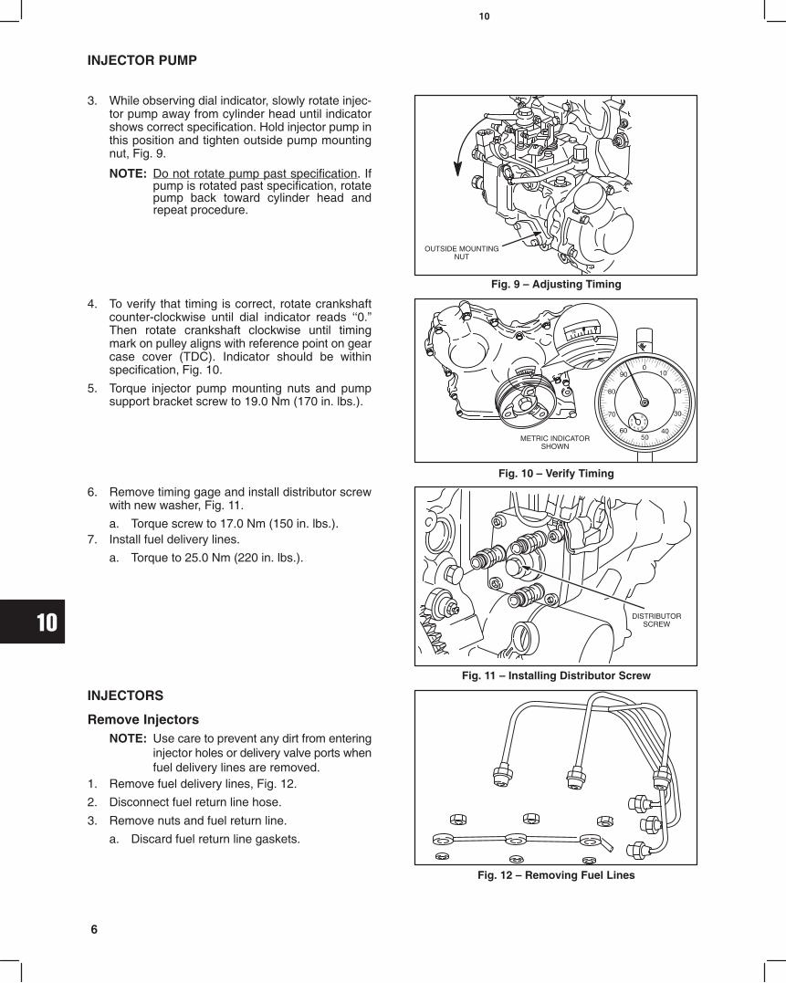
10
6
INJECTOR PUMP
3. While observing dial indicator, slowly rotate injec-tor pump away from cylinder head until indicatorshows correct specification. Hold injector pump inthis position and tighten outside pump mountingnut, Fig. 9.
NOTE: Do not rotate pump past specification. Ifpump is rotated past specification, rotatepump back toward cylinder head andrepeat procedure.
Fig. 9 Adjusting Timing
OUTSIDE MOUNTINGNUT
4. To verify that timing is correct, rotate crankshaftcounter-clockwise until dial indicator reads 0.Then rotate crankshaft clockwise until timingmark on pulley aligns with reference point on gearcase cover (TDC). Indicator should be withinspecification, Fig. 10.
5. Torque injector pump mounting nuts and pumpsupport bracket screw to 19.0 Nm (170 in. lbs.).
Fig. 10 Verify Timing
METRIC INDICATORSHOWN
6. Remove timing gage and install distributor screwwith new washer, Fig. 11.
a. Torque screw to 17.0 Nm (150 in. lbs.).7. Install fuel delivery lines.
a. Torque to 25.0 Nm (220 in. lbs.).
Fig. 11 Installing Distributor Screw
DISTRIBUTORSCREW
INJECTORS
Remove InjectorsNOTE: Use care to prevent any dirt from entering
injector holes or delivery valve ports whenfuel delivery lines are removed.
1. Remove fuel delivery lines, Fig. 12.
2. Disconnect fuel return line hose.
3. Remove nuts and fuel return line.
a. Discard fuel return line gaskets.
Fig. 12 Removing Fuel Lines
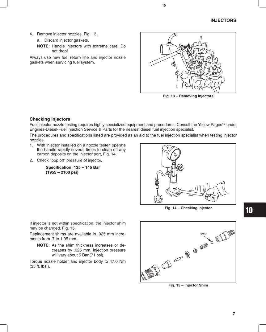
10
7
INJECTORS
4. Remove injector nozzles, Fig. 13.
a. Discard injector gaskets.NOTE: Handle injectors with extreme care. Do
not drop!
Always use new fuel return line and injector nozzlegaskets when servicing fuel system.
Fig. 13 Removing Injectors
Checking InjectorsFuel injector nozzle testing requires highly specialized equipment and procedures. Consult the Yellow Pages underEngines-Diesel-Fuel Injection Service & Parts for the nearest diesel fuel injection specialist.The procedures and specifications listed are provided as an aid to the fuel injection specialist when testing injectornozzles.1. With injector installed on a nozzle tester, operate
the handle rapidly several times to clean off anycarbon deposits on the injector port, Fig. 14.
2. Check pop off pressure of injector.
Specification: 135 145 Bar(1955 2100 psi)
Fig. 14 Checking Injector
If injector is not within specification, the injector shimmay be changed, Fig. 15.Replacement shims are available in .025 mm incre-ments from .7 to 1.95 mm.
NOTE: As the shim thickness increases or de-creases by .025 mm, injection pressurewill vary about 5 Bar (71 psi).
Torque nozzle holder and injector body to 47.0 Nm(35 ft. lbs.).
Fig. 15 Injector Shim
SHIM

10
8
INJECTORS
3. Check injector for leakage, Fig. 16.
Maintain injector pressure at approximately 120 Bar(1707 psi), for about 10 seconds. Make sure there is noleakage from nozzle or retaining nut area.
Fig. 16 Checking Leakage
4. Check spray pattern of nozzle, Fig. 17.
Operate tester handle rapidly while observing pattern.Spray pattern should be uniform and centered undernozzle.
NOTE: A buzzing or chattering sound should alsooccur while operating handle. Nozzleshould not drip between pump strokes.
Fig. 17 Checking Spray Pattern
Install InjectorsInstall injectors and fuel return line with new gaskets,Fig. 18. Install fuel delivery lines.
a. Torque injectors to 61.0 Nm (45 ft. lbs.).b. Torque fuel return line to 27.0 Nm (20 ft. lbs.).c. Torque fuel delivery lines to 25.0 Nm
(220 in. lbs.).
Fig. 18 Installing Injectors
FUEL FILTER GENERALThe fuel filter consists of a replaceable cartridge typefilter with a water level sensor and priming pump,Fig. 19.
Replace fuel filter cartridge every 800 hours of engineoperation.
The water collector contains a float type sensor thatactivates a warning lamp when it collects a minimum of80 ccs (2.5 fl. oz.) of water.
Fig. 19 Fuel Filter
DRAIN PLUG
FILTER
O-RING
FLOATVENT PLUG
PRIMER BUTTON

10
9
FUEL FILTER
Draining Water CollectorWhen warning lamp comes on, drain water collectoras follows:1. Stop engine.
2. Place a drain pan under filter and loosen vent plug.
3. Loosen drain plug approximately 1 turn and drainwater from filter until only fuel flows from filter.
4. Tighten drain plug and vent plug and wipe up anyspills.
5. Start engine, making sure warning lamp goes out.Check for leaks.
Change Fuel Filter1. Disconnect sensor wire and remove drain plug.
Discard O-ring.
2. Remove fuel filter with a filter wrench.
3. Screw new filter on by hand until gasket contactshousing. Then tighten 1/3 turn more.
4. Install drain plug with new O-ring and connectsensor wire.
5. Activate primer button until resistance is felt.
6. Start engine and check for leaks.
Checking Float SensorThe following test will be made with the meter in the
Diode Test Position .
Disconnect sensor wire from equipment harness andremove float sensor from fuel filter.1. Attach a meter test lead to each terminal in
connector.
2. While holding drain plug in vertical position, raisefloat to end of travel, Fig. 20.
a. Meter should make a continuous tone.3. Now lower float
a. Meter should display OL.
Replace drain plug and float sensor if not to specification.
Fig. 20 Checking Sensor
FLOAT
FUEL SHUT-OFF SOLENOIDWhen the ignition switch is turned to the On andStart position the fuel shut off solenoid valve opensallowing fuel to enter the fill port and pressurechamber. When the keyswitch is turned Off thesolenoid closes shutting off the the fuel supply and theengine, Fig. 21.
Solenoid is operating if a click is heard when keyswitchis turned On and Off.
If solenoid does not click, problem may be in equip-ment wiring to solenoid. Fig. 21 Fuel Shut-Off Solenoid
FUELSHUT-OFFSOLENOID
Checking Fuel Shut-Off Solenoid WiringThe following test will be made with the meter in the
(DC Volts position).
Turn keyswitch to Off position and disconnectequipment solenoid wire.1. Attach BLACK meter test lead to a good ground.
2. Attach RED meter test lead to connector in equip-ment solenoid wire and turn keyswitch to Onposition.
3. Meter should display battery voltage, Fig. 22.
a. If meter does not display battery voltage,check for broken solenoid wire, blown fuse (ifequipped) or defective keyswitch.
Fig. 22 Testing Solenoid Wiring
EQUIPMENTWIRING HARNESS
CONNECTOR
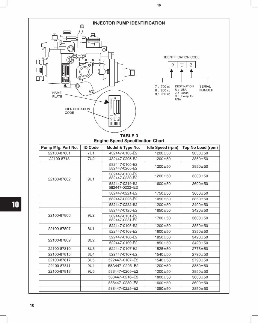
10
10
TABLE 3Engine Speed Specification Chart
Pump Mfg. Part No. ID Code Model & Type No. Idle Speed (rpm) Top No Load (rpm)22100-87801 7U1 432447-0105-E2 120050 385050
22100-8713 7U2 432447-0205-E2 120050 385050
582447-0105-E2582447-0205-E2 120050 385050
22100-87802 9U1582447-0130-E2582447-0230-E2 120050 330050
22100 87802 9U1582447-0219-E2582447-0222E2
160050 360050
582447-0221-E2 175050 360050
582447-0225-E2 105050 385050
582447-0232-E2 120050 340050
582447-0125-E2 185050 34205022100-87806 9U2 582447-0131-E2
582447-0231-E2 170050 360050
22100 87807 8U1522447-0105-E2 120050 385050
22100-87807 8U1522447-0108-E2 160050 335050
22100 87809 8U2522447-0106-E2 185050 342050
22100-87809 8U2522447-0109-E2 185050 342050
22100-87810 8U3 522447-0107-E2 152550 277550
22100-87815 8U4 522447-0107-E2 154050 279050
22100-87817 8U5 5224470107E2 154050 279050
22100-87811 9U4 58A4470205E2 120050 385050
22100-87818 9U5 5884470205E2 120050 385050
5884470216E2 180050 360050
5884470230E2 160050 360050
5884470225E2 105050 385050
NAMEPLATE
IDENTIFICATIONCODE
IDENTIFICATION CODE
7 : 700 cc8 : 850 cc9 : 950 cc
DESTINATIONU : USAJ : JapanX : Except forUSA
SERIALNUMBER
INJECTOR PUMP IDENTIFICATION
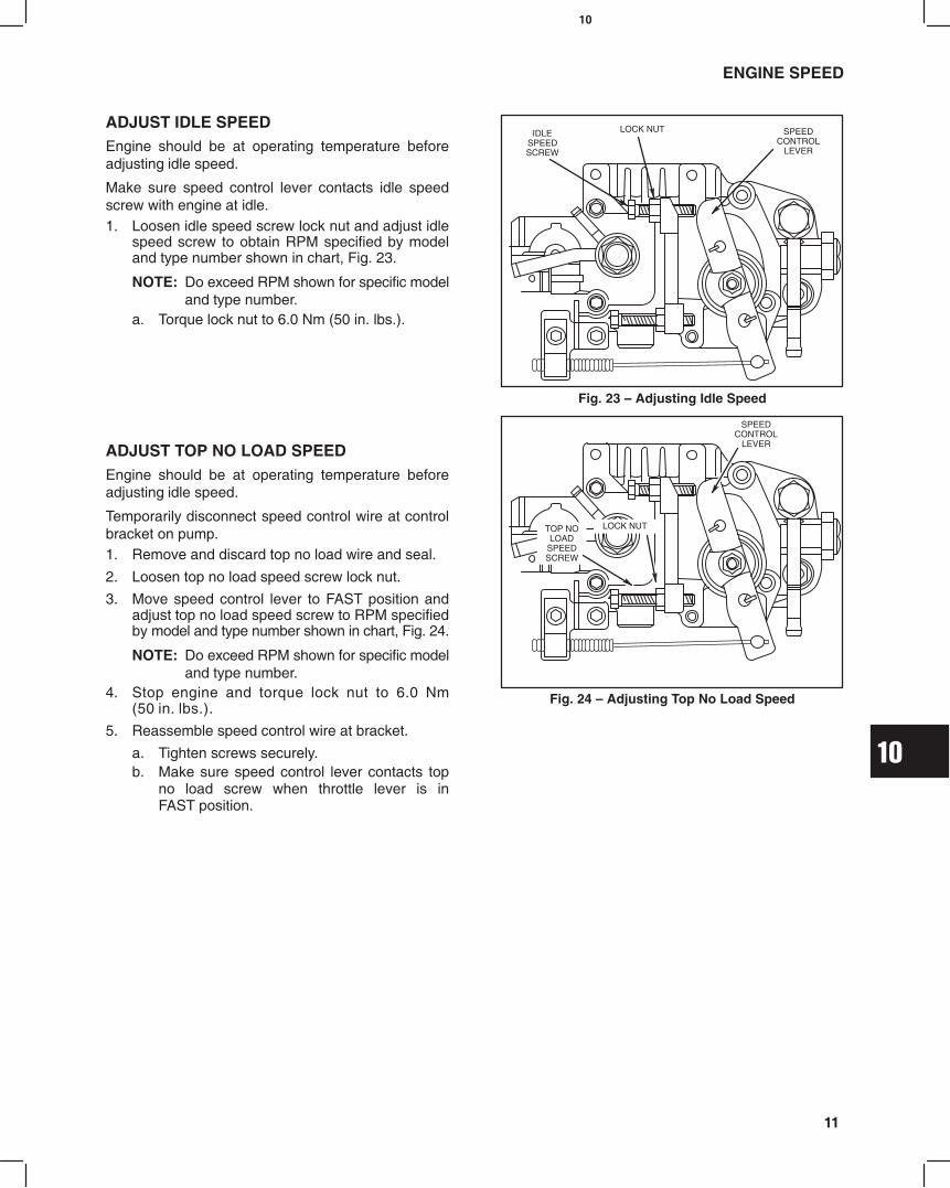
10
11
ENGINE SPEED
ADJUST IDLE SPEEDEngine should be at operating temperature beforeadjusting idle speed.
Make sure speed control lever contacts idle speedscrew with engine at idle.1. Loosen idle speed screw lock nut and adjust idle
speed screw to obtain RPM specified by modeland type number shown in chart, Fig. 23.
NOTE: Do exceed RPM shown for specific modeland type number.
a. Torque lock nut to 6.0 Nm (50 in. lbs.).
Fig. 23 Adjusting Idle Speed
IDLESPEEDSCREW
SPEEDCONTROL
LEVER
LOCK NUT
ÏÏÏÏÏÏÏÏÏÏÏÏ
ADJUST TOP NO LOAD SPEEDEngine should be at operating temperature beforeadjusting idle speed.
Temporarily disconnect speed control wire at controlbracket on pump.1. Remove and discard top no load wire and seal.
2. Loosen top no load speed screw lock nut.
3. Move speed control lever to FAST position andadjust top no load speed screw to RPM specifiedby model and type number shown in chart, Fig. 24.
NOTE: Do exceed RPM shown for specific modeland type number.
4. Stop engine and torque lock nut to 6.0 Nm(50 in. lbs.).
5. Reassemble speed control wire at bracket.
a. Tighten screws securely.b. Make sure speed control lever contacts top
no load screw when throttle lever is inFAST position.
ÏÏÏÏÏÏÏÏ
Fig. 24 Adjusting Top No Load Speed
TOP NOLOAD
SPEEDSCREW
SPEEDCONTROL
LEVER
LOCK NUT

11
MAY 2002 1
Section 11Electrical System
Section Contents
Page
ELECTRICAL SYSTEM COMPONENTS 3. . . . . . . . . . . . . . . . . . . . . . . . . . . . . . . . . . . . . . . . . . . . . . . . . . . . GLOW PLUG SYSTEM
Glow Plug Specifications 4. . . . . . . . . . . . . . . . . . . . . . . . . . . . . . . . . . . . . . . . . . . . . . . . . . . . . . . . . . . . . . . Remove Glow Plugs 4. . . . . . . . . . . . . . . . . . . . . . . . . . . . . . . . . . . . . . . . . . . . . . . . . . . . . . . . . . . . . . . . . . . Test Equipment 4. . . . . . . . . . . . . . . . . . . . . . . . . . . . . . . . . . . . . . . . . . . . . . . . . . . . . . . . . . . . . . . . . . . . . . . Testing Glow Plug 4. . . . . . . . . . . . . . . . . . . . . . . . . . . . . . . . . . . . . . . . . . . . . . . . . . . . . . . . . . . . . . . . . . . . .
PREHEAT TIMER AND GLOW RELAY 5. . . . . . . . . . . . . . . . . . . . . . . . . . . . . . . . . . . . . . . . . . . . . . . . . . . . . . Testing Preheat Timer 5. . . . . . . . . . . . . . . . . . . . . . . . . . . . . . . . . . . . . . . . . . . . . . . . . . . . . . . . . . . . . . . . . Testing Glow Relay 5. . . . . . . . . . . . . . . . . . . . . . . . . . . . . . . . . . . . . . . . . . . . . . . . . . . . . . . . . . . . . . . . . . . .
KEYSWITCHES 6. . . . . . . . . . . . . . . . . . . . . . . . . . . . . . . . . . . . . . . . . . . . . . . . . . . . . . . . . . . . . . . . . . . . . . . . . . 14 AMP CHARGING SYSTEM 7. . . . . . . . . . . . . . . . . . . . . . . . . . . . . . . . . . . . . . . . . . . . . . . . . . . . . . . . . . . . .
Test Equipment 7. . . . . . . . . . . . . . . . . . . . . . . . . . . . . . . . . . . . . . . . . . . . . . . . . . . . . . . . . . . . . . . . . . . . . . . Testing Alternator AC Output 8. . . . . . . . . . . . . . . . . . . . . . . . . . . . . . . . . . . . . . . . . . . . . . . . . . . . . . . . . . Testing Regulator-rectifier DC Output 8. . . . . . . . . . . . . . . . . . . . . . . . . . . . . . . . . . . . . . . . . . . . . . . . . . Charging Indicator Circuit 9. . . . . . . . . . . . . . . . . . . . . . . . . . . . . . . . . . . . . . . . . . . . . . . . . . . . . . . . . . . . . . Testing Charging Indicator Bulb And Wiring 9. . . . . . . . . . . . . . . . . . . . . . . . . . . . . . . . . . . . . . . . . . . . . . .
40 AMP CHARGING SYSTEM 10. . . . . . . . . . . . . . . . . . . . . . . . . . . . . . . . . . . . . . . . . . . . . . . . . . . . . . . . . . . . Test Equipment 10. . . . . . . . . . . . . . . . . . . . . . . . . . . . . . . . . . . . . . . . . . . . . . . . . . . . . . . . . . . . . . . . . . . . . . Testing Alternator DC Output 10. . . . . . . . . . . . . . . . . . . . . . . . . . . . . . . . . . . . . . . . . . . . . . . . . . . . . . . . Disassemble Alternator 11. . . . . . . . . . . . . . . . . . . . . . . . . . . . . . . . . . . . . . . . . . . . . . . . . . . . . . . . . . . . . . . . Checking Bearings 12. . . . . . . . . . . . . . . . . . . . . . . . . . . . . . . . . . . . . . . . . . . . . . . . . . . . . . . . . . . . . . . . . . . Install Ball Bearing 13. . . . . . . . . . . . . . . . . . . . . . . . . . . . . . . . . . . . . . . . . . . . . . . . . . . . . . . . . . . . . . . . . . . Checking Rotor 13. . . . . . . . . . . . . . . . . . . . . . . . . . . . . . . . . . . . . . . . . . . . . . . . . . . . . . . . . . . . . . . . . . . . . . Check Brushes 13. . . . . . . . . . . . . . . . . . . . . . . . . . . . . . . . . . . . . . . . . . . . . . . . . . . . . . . . . . . . . . . . . . . . . . Check Regulator 14. . . . . . . . . . . . . . . . . . . . . . . . . . . . . . . . . . . . . . . . . . . . . . . . . . . . . . . . . . . . . . . . . . . . . Check Rectifier 14. . . . . . . . . . . . . . . . . . . . . . . . . . . . . . . . . . . . . . . . . . . . . . . . . . . . . . . . . . . . . . . . . . . . . . Assemble Alternator 14. . . . . . . . . . . . . . . . . . . . . . . . . . . . . . . . . . . . . . . . . . . . . . . . . . . . . . . . . . . . . . . . . .
BRIGGS & STRATTON DAIHATSU 3 CYLINDERLIQUID-COOLED DIESEL ENGINE REPAIR MANUAL (MS-1055)

11
2
Section Contents (Continued)
Page
STARTER SYSTEM GENERAL INFORMATIONSTARTER CURRENT DRAW TEST INSTALLED 17. . . . . . . . . . . . . . . . . . . . . . . . . . . . . . . . . . . . . . . . . .
Test Equipment 17. . . . . . . . . . . . . . . . . . . . . . . . . . . . . . . . . . . . . . . . . . . . . . . . . . . . . . . . . . . . . . . . . . . . . . Testing Starter 18. . . . . . . . . . . . . . . . . . . . . . . . . . . . . . . . . . . . . . . . . . . . . . . . . . . . . . . . . . . . . . . . . . . . . . .
STARTER CURRENT DRAW TEST NO LOAD 18. . . . . . . . . . . . . . . . . . . . . . . . . . . . . . . . . . . . . . . . . . . . Testing Starter (No Load) 18. . . . . . . . . . . . . . . . . . . . . . . . . . . . . . . . . . . . . . . . . . . . . . . . . . . . . . . . . . . . .
STARTER SOLENOIDTest Equipment 19. . . . . . . . . . . . . . . . . . . . . . . . . . . . . . . . . . . . . . . . . . . . . . . . . . . . . . . . . . . . . . . . . . . . . . Testing Solenoid 19. . . . . . . . . . . . . . . . . . . . . . . . . . . . . . . . . . . . . . . . . . . . . . . . . . . . . . . . . . . . . . . . . . . . . Remove Solenoid 20. . . . . . . . . . . . . . . . . . . . . . . . . . . . . . . . . . . . . . . . . . . . . . . . . . . . . . . . . . . . . . . . . . . . Remove Pinion And Clutch Assembly 20. . . . . . . . . . . . . . . . . . . . . . . . . . . . . . . . . . . . . . . . . . . . . . . . . . . Check Pinion And Clutch Assembly 21. . . . . . . . . . . . . . . . . . . . . . . . . . . . . . . . . . . . . . . . . . . . . . . . . . . . Assemble Pinion And Clutch Assembly 21. . . . . . . . . . . . . . . . . . . . . . . . . . . . . . . . . . . . . . . . . . . . . . . . . Install Solenoid 22. . . . . . . . . . . . . . . . . . . . . . . . . . . . . . . . . . . . . . . . . . . . . . . . . . . . . . . . . . . . . . . . . . . . . . Install Solenoid Contacts And Plunger 22. . . . . . . . . . . . . . . . . . . . . . . . . . . . . . . . . . . . . . . . . . . . . . . . . .
DISASSEMBLE STARTER MOTOR 24. . . . . . . . . . . . . . . . . . . . . . . . . . . . . . . . . . . . . . . . . . . . . . . . . . . . . . . Inspect Armature Commutator 24. . . . . . . . . . . . . . . . . . . . . . . . . . . . . . . . . . . . . . . . . . . . . . . . . . . . . . . . . Inspect Brushes 24. . . . . . . . . . . . . . . . . . . . . . . . . . . . . . . . . . . . . . . . . . . . . . . . . . . . . . . . . . . . . . . . . . . . . Replace Brushes 25. . . . . . . . . . . . . . . . . . . . . . . . . . . . . . . . . . . . . . . . . . . . . . . . . . . . . . . . . . . . . . . . . . . . .
ASSEMBLE STARTER MOTOR 26. . . . . . . . . . . . . . . . . . . . . . . . . . . . . . . . . . . . . . . . . . . . . . . . . . . . . . . . . . . WIRING DIAGRAMS14 AMP WIRING DIAGRAMS 27. . . . . . . . . . . . . . . . . . . . . . . . . . . . . . . . . . . . . . . . . . . . . . . . . . . . . . . . . . . . . 40 AMP WIRING DIAGRAMS 28. . . . . . . . . . . . . . . . . . . . . . . . . . . . . . . . . . . . . . . . . . . . . . . . . . . . . . . . . . . . .

11
3
40 AMPALTERNATOR
Fig. 1
Electrical System Components(Typical 40 Amp Alternator Shown)
12 VOLT BATTERY
STARTER MOTOR
SOLENOID
INJECTION PUMP
GLOWLIGHT
PREHEATING TIMER
GLOWRELAY
FUEL FILTER
WATER INDICATORLIGHT
CHARGE INDICATORLIGHT
BTERMINAL
IGTERMINAL
3 4
5
6
7
1
2
8
IGTERMINAL
LTERMINAL
BTERMINAL
LTERMINAL
GLOW PLUGS
KEYSWITCH
2
4
5
ACCESSORY & PREHEAT TIMER
SOLENOID & PREHEAT TIMER
BATTERY
KEYSWITCHTERMINAL FUNCTION
6
3
5
4
2
1
NOTE: TERMINALS 1, 3, 6 NOT USED
PART NO.493625
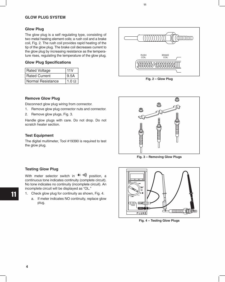
11
4
GLOW PLUG SYSTEM
Glow PlugThe glow plug is a self regulating type, consisting oftwo metal heating element coils; a rush coil and a brakecoil, Fig. 2. The rush coil provides rapid heating of thetip of the glow plug. The brake coil decreases current tothe glow plug by increasing resistance as the tempera-ture rises, regulating the temperature of the glow plug.
Glow Plug Specifications
Rated Voltage 11VRated Current 9.5ANormal Resistance 1.0 Ω
Fig. 2 Glow Plug
RUSHCOIL
BRAKE COIL
Remove Glow PlugDisconnect glow plug wiring from connector.1. Remove glow plug connector nuts and connector.
2. Remove glow plugs, Fig. 3.
Handle glow plugs with care. Do not drop. Do notscratch heater section.
Test EquipmentThe digital multimeter, Tool #19390 is required to testthe glow plug.
Fig. 3 Removing Glow Plugs
Testing Glow Plug
With meter selector switch in position, acontinuous tone indicates continuity (complete circuit).No tone indicates no continuity (incomplete circuit). Anincomplete circuit will be displayed as OL.1. Check glow plug for continuity as shown, Fig. 4.
a. If meter indicates NO continuity, replace glowplug.
Fig. 4 Testing Glow Plugs

11
5
GLOW PLUG SYSTEM
PREHEAT TIMER AND GLOW RELAYThe preheat timer and glow relay regulate current tothe glow plugs for preheating and starting. When thekeyswitch is turned to the On position, with the enginecold, the preheat timer activates the glow plugs. Anindicator light lights and remains on while the glowplugs are preheating the combustion chamber. Whenthe indicator light goes out, the engine may be started.When the keyswitch is in the Start position, the glowplugs and light are activated again as the engine iscranking.
See Fig. 5 for terminal positions of the preheat timerand glow relay. Fig. 5 Terminal Positions
PREHEAT TIMERGLOWRELAY
34
5
671
2
8
Testing Preheat TimerThe following test will be made with the meter in the
(DC Volts position), Fig. 6.
Turn keyswitch to Off position.1. Insert BLACK meter test lead probe into terminal
#4.
2. Insert RED meter test lead probe into terminal #3.
3. Turn keyswitch to On position.
a. Glow light should light. Meter should display1.5 volts maximum.
b. After 5 seconds (approximately), glow lightshould go out. Meter should display approxi-mately battery voltage.
4. Replace preheat timer if not to specification.
NOTE: If glow light does not light, replace bulb.Fig. 6 Testing Preheat Timer
3 4
1
2
Testing Glow RelayThe following test will be made with the meter in the
(DC Volts position), Fig. 7.
Turn keyswitch to Off position.1. Insert BLACK meter test lead probe into terminal
#8.
2. Insert RED meter test lead probe into terminal #7.
a. Meter should display battery voltage.3. Turn keyswitch to On position.
a. Glow light should light. Meter should display0.5 volts maximum.
b. After 5 seconds (approximately), glow lightshould go out. Meter should displayapproximate battery voltage.
4. Replace glow relay if not to specification.Fig. 7 Testing Glow Relay
5
67
8

11
6
GLOW PLUG SYSTEM
KEYSWITCHESTwo types of keyswitches may be used on Briggs &Stratton Daihatsu diesel engines.
Fixed Timer Preheat Keyswitch Part No. 493625Keyswitch, Part No. 493625, is used with a preheattimer and glow relay, Fig. 8. With the keyswitch in theOn and Start position, battery current is supplied tothe preheat timer and glow relay. See keyswitchterminal positions and functions, Fig. 8.
See Fig. 78 and Fig. 79 at end of section, for wiringdiagrams for keyswitch No. 493625.
Fig. 8 Keyswitch Fixed Timer Preheat
1 + 3 + 6 2 + 4 +5ON
OFF START
2 + 5
NOTUSED
6
3
5
4
2
1
2
4
5
Accessory & Preheat Timer
Solenoid & Preheat Timer
Battery
6
3
5
4
2
1
ON START
Test switch terminals for continuity with key-switch in positions shown
NOTE: Terminals 1, 3, 6 Not Used
Manual Preheat Keyswitch Part No. 825129The manual preheat keyswitch, Part No. 825129, isequipped with four positions and six terminals, Fig. 9.The G1 terminal provides current to the glow plugsonly when the switch is in the Heat position. When thekeyswitch is turned to the Start position the G2terminal provides current to the glow plugs while theengine is cranking. See keyswitch terminal positionsand functions, Fig. 10.Symbols are shown as they appear on rear ofkeyswitch. Note that B terminal is connected toterminal below it, Fig. 10. Keyswitch will not functionwithout connector.
Fig. 9 Keyswitch Manual Preheat
B+B+G1 B+B+MONHEAT
OFF
START
B+B
B+B+S+M+G2
See Fig. 80 and Fig. 81 for wiring diagrams forkeyswitch No. 825129.
S
G1
G2
M
BS
G1
G2
M
BS
G1
G2
M
BS
G1
G2
M
B
HEAT OFF ON START
B
S
G1
G2
M
Battery (2)
Solenoid
Glow Plug (Preheat)
Glow Plug (Cranking)
Accessory
Fig. 10 Terminal Positions And Functions
Test switch terminals for continuity with keyswitch in positions shown.
B+B+G1 B+B B+B+M B+B+S+M+G2
B B B B
Connector
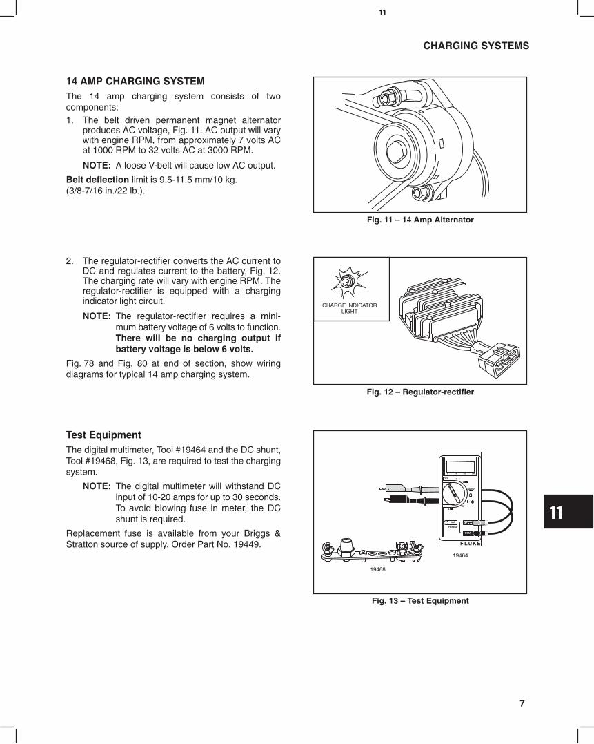
11
7
CHARGING SYSTEMS
14 AMP CHARGING SYSTEMThe 14 amp charging system consists of twocomponents:1. The belt driven permanent magnet alternator
produces AC voltage, Fig. 11. AC output will varywith engine RPM, from approximately 7 volts ACat 1000 RPM to 32 volts AC at 3000 RPM.
NOTE: A loose V-belt will cause low AC output.
Belt deflection limit is 9.5-11.5 mm/10 kg.(3/8-7/16 in./22 lb.).
Fig. 11 14 Amp Alternator
2. The regulator-rectifier converts the AC current toDC and regulates current to the battery, Fig. 12.The charging rate will vary with engine RPM. Theregulator-rectifier is equipped with a chargingindicator light circuit.
NOTE: The regulator-rectifier requires a mini-mum battery voltage of 6 volts to function.There will be no charging output ifbattery voltage is below 6 volts.
Fig. 78 and Fig. 80 at end of section, show wiringdiagrams for typical 14 amp charging system.
Fig. 12 Regulator-rectifier
CHARGE INDICATORLIGHT
Test EquipmentThe digital multimeter, Tool #19464 and the DC shunt,Tool #19468, Fig. 13, are required to test the chargingsystem.
NOTE: The digital multimeter will withstand DCinput of 10-20 amps for up to 30 seconds.To avoid blowing fuse in meter, the DCshunt is required.
Replacement fuse is available from your Briggs &Stratton source of supply. Order Part No. 19449.
Fig. 13 Test Equipment
19464
19468

11
8
CHARGING SYSTEMS
Testing Alternator AC OutputThe alternator output test will be performed with themeter in the V~ (AC volts) position, Fig. 14.
Disconnect alternator wires at connector.
Attach meter test leads to alternator output connectorsBEFORE starting engine, Fig. 14.1. With the engine running at 3300 RPM the output
should be no less than 28 volts AC.
a. If no output or low output is found, replacealternator.
b. If alternator output is within specification, re-connect alternator wires and test regulatorrectifier.
Fig. 14 Testing Alternator Output
Testing Regulator-Rectifier DC OutputThe DC Shunt must be installed on the negative (-)terminal of the battery, Fig. 15. All connections must beclean and tight for correct amperage readings.
Attach meter test leads BEFORE starting engine.
The regulator-rectifier test will be performed with the
meter in the position.1. Attach RED meter test lead to RED post terminal
on shunt.
2. Attach BLACK meter test lead to BLACK postterminal on shunt.
Fig. 15 DC Shunt Installation
BLACKLEAD
REDLEAD
NEGATIVEBATTERY
TERMINAL
ATTACH NEGATIVEBATTERY CABLE
3. With the engine running at 3300 RPM, the outputshould be:
* 4 14 Amps
* Depending upon battery voltage and/or current drawon system.4. If no or low output is found, be sure that regulator-
rectifier is grounded properly and all connectionsare clean and secure. If there is still no or lowoutput, replace the regulator-rectifier.
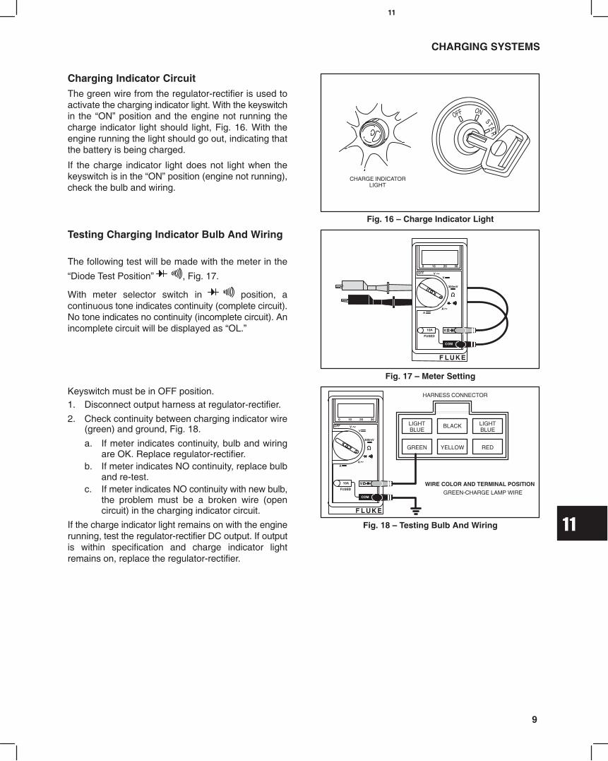
11
9
CHARGING SYSTEMS
Charging Indicator CircuitThe green wire from the regulator-rectifier is used toactivate the charging indicator light. With the keyswitchin the ON position and the engine not running thecharge indicator light should light, Fig. 16. With theengine running the light should go out, indicating thatthe battery is being charged.
If the charge indicator light does not light when thekeyswitch is in the ON position (engine not running),check the bulb and wiring.
Fig. 16 Charge Indicator Light
CHARGE INDICATORLIGHT
Testing Charging Indicator Bulb And Wiring
The following test will be made with the meter in the
Diode Test Position , Fig. 17.
With meter selector switch in position, acontinuous tone indicates continuity (complete circuit).No tone indicates no continuity (incomplete circuit). Anincomplete circuit will be displayed as OL.
Fig. 17 Meter Setting
Keyswitch must be in OFF position.1. Disconnect output harness at regulator-rectifier.
2. Check continuity between charging indicator wire(green) and ground, Fig. 18.
a. If meter indicates continuity, bulb and wiringare OK. Replace regulator-rectifier.
b. If meter indicates NO continuity, replace bulband re-test.
c. If meter indicates NO continuity with new bulb,the problem must be a broken wire (opencircuit) in the charging indicator circuit.
If the charge indicator light remains on with the enginerunning, test the regulator-rectifier DC output. If outputis within specification and charge indicator lightremains on, replace the regulator-rectifier.
Fig. 18 Testing Bulb And Wiring
HARNESS CONNECTOR
WIRE COLOR AND TERMINAL POSITION
GREEN-CHARGE LAMP WIRE
LIGHTBLUE
GREEN YELLOW
BLACK
RED
LIGHTBLUE
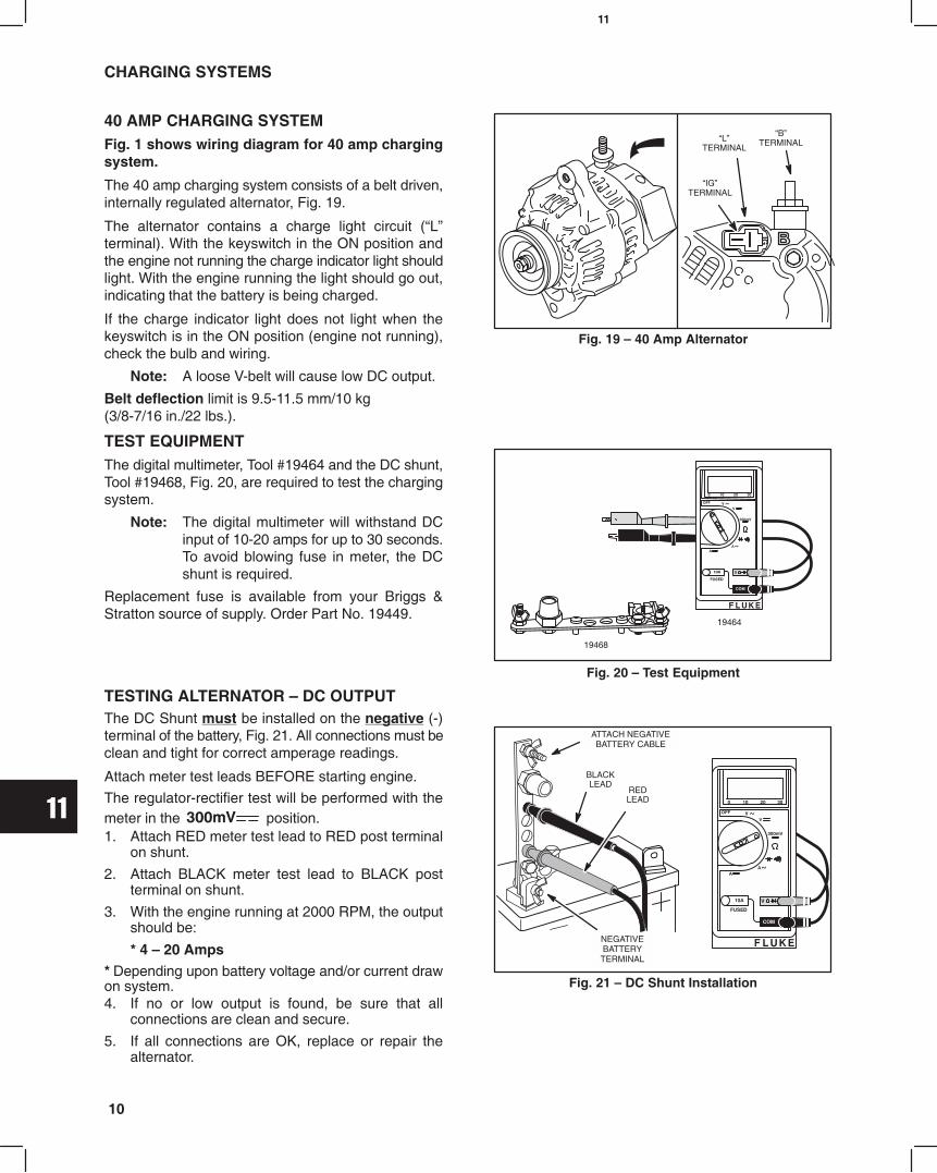
11
10
CHARGING SYSTEMS
40 AMP CHARGING SYSTEMFig. 1 shows wiring diagram for 40 amp chargingsystem.
The 40 amp charging system consists of a belt driven,internally regulated alternator, Fig. 19.
The alternator contains a charge light circuit (Lterminal). With the keyswitch in the ON position andthe engine not running the charge indicator light shouldlight. With the engine running the light should go out,indicating that the battery is being charged.
If the charge indicator light does not light when thekeyswitch is in the ON position (engine not running),check the bulb and wiring.
Note: A loose V-belt will cause low DC output.
Belt deflection limit is 9.5-11.5 mm/10 kg(3/8-7/16 in./22 lbs.).
Fig. 19 40 Amp Alternator
IGTERMINAL
LTERMINAL
BTERMINAL
TEST EQUIPMENTThe digital multimeter, Tool #19464 and the DC shunt,Tool #19468, Fig. 20, are required to test the chargingsystem.
Note: The digital multimeter will withstand DCinput of 10-20 amps for up to 30 seconds.To avoid blowing fuse in meter, the DCshunt is required.
Replacement fuse is available from your Briggs &Stratton source of supply. Order Part No. 19449.
Fig. 20 Test Equipment
19464
19468
TESTING ALTERNATOR DC OUTPUTThe DC Shunt must be installed on the negative (-)terminal of the battery, Fig. 21. All connections must beclean and tight for correct amperage readings.
Attach meter test leads BEFORE starting engine.
The regulator-rectifier test will be performed with themeter in the position.1. Attach RED meter test lead to RED post terminal
on shunt.
2. Attach BLACK meter test lead to BLACK postterminal on shunt.
3. With the engine running at 2000 RPM, the outputshould be:
* 4 20 Amps* Depending upon battery voltage and/or current drawon system.4. If no or low output is found, be sure that all
connections are clean and secure.
5. If all connections are OK, replace or repair thealternator.
Fig. 21 DC Shunt Installation
BLACKLEAD
REDLEAD
NEGATIVEBATTERY
TERMINAL
ATTACH NEGATIVEBATTERY CABLE

11
11
CHARGING SYSTEMS
DISASSEMBLE ALTERNATOR1. Remove pulley nut using tool #19491 and 10 mm
deep socket as shown in Fig. 22.
a. Remove pulley and spacer.Replace pulley if damaged or worn.
Fig. 22 Remove Pulley
2. Remove nut and insulator at B terminal.
3. Remove three screws and brush cover, Fig. 23.
Fig. 23 Remove Rear Cover
BTERMINAL
4. Remove two screws, then brush retainerassembly, Fig. 24.
Important: Length of brush retainer screws aredifferent. Do not mix. Screw A: 11.5 mmScrew B: 9.0 mm
Fig. 24 Remove Brush Retainer
A11.5 mm
B9.0 mm
5. Remove three screws and regulator, Fig. 25.
Fig. 25 Remove Regulator
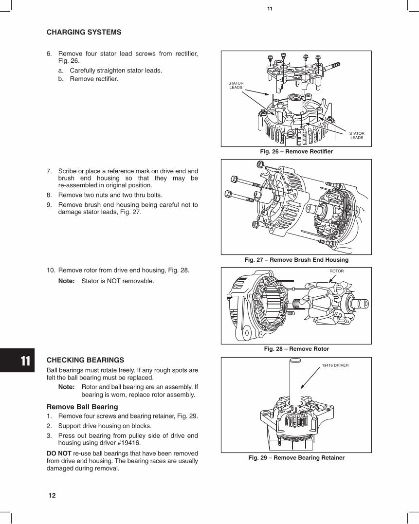
11
12
CHARGING SYSTEMS
6. Remove four stator lead screws from rectifier,Fig. 26.
a. Carefully straighten stator leads.b. Remove rectifier.
Fig. 26 Remove Rectifier
STATORLEADS
STATORLEADS
7. Scribe or place a reference mark on drive end andbrush end housing so that they may bere-assembled in original position.
8. Remove two nuts and two thru bolts.
9. Remove brush end housing being careful not todamage stator leads, Fig. 27.
Fig. 27 Remove Brush End Housing
10. Remove rotor from drive end housing, Fig. 28.
Note: Stator is NOT removable.
Fig. 28 Remove Rotor
ROTOR
CHECKING BEARINGSBall bearings must rotate freely. If any rough spots arefelt the ball bearing must be replaced.
Note: Rotor and ball bearing are an assembly. Ifbearing is worn, replace rotor assembly.
Remove Ball Bearing1. Remove four screws and bearing retainer, Fig. 29.
2. Support drive housing on blocks.
3. Press out bearing from pulley side of drive endhousing using driver #19416.
DO NOT re-use ball bearings that have been removedfrom drive end housing. The bearing races are usuallydamaged during removal.
Fig. 29 Remove Bearing Retainer
19416 DRIVER

11
13
CHARGING SYSTEMS
INSTALL BALL BEARING1. Lightly lubricate bearing O.D. with engine oil.
2. Press in new bearing using bearing driver #19226,Fig. 30.
3. Install retainer and four screws.
Fig. 30 Install Ball Bearing
19226 DRIVER
CHECKING ROTORThe following test will be made with the meter in the
Diode Test Position .1. Use digital multimeter and check for continuity
between slip rings as shown, Fig. 31.
a. Meter should make continuous tone(continuity).
b. If meter displays OL, (no continuity) replacerotor.
2. Check for continuity between slip ring and rotorshaft.
a. Meter should display OL, (no continuity). Fig. 31 Check Rotor
1
2
3. Measure slip ring diameter, Fig. 32.
STD: 14.4 mm (.567)Reject: 14.0 mm (.551)
Slip rings may be cleaned with fine sandpaper (#300 500 grit).
Fig. 32 Check Slip Ring
CHECK BRUSHESMeasure length of brushes protruding from brushholder, Fig. 33.
STD: 10.5 mm (.413)Reject: 8.0 mm (.315)
Fig. 33 Check Brushes

11
14
CHARGING SYSTEMS
CHECK REGULATORThe following test will be made with the meter in the
Diode Test Position .1. Attach BLACK meter test lead to terminal A as
shown, Fig. 34.
2. Contact terminal B with RED meter test lead,Fig. 34.
a. Meter should beep once.b. If meter displays OL or makes a continuous
tone, regulator is defective. Replace regulator.
Fig. 34 Check Regulator
B
A
CHECK RECTIFIERThe following test will be made with the meter in the
Diode Test Position .1. Attach BLACK meter test lead to B terminal,
Fig. 35. Leave attached through Step 3.
2. Contact #1 terminal with RED meter test lead,Fig. 35.
a. Meter should beep once.b. If meter displays OL or makes a continuous
tone, diode is defective. Replace rectifier.3. Repeat test at #2, #3 and #4 terminals.
a. Results must be the same. Fig. 35 Check Rectifier
#4
#3#2
#1
BTERMINAL
4. Attach RED test lead to one of the three rectifiermounting holes, Fig. 36. Leave attached throughStep 6.
5. Contact #1 terminal with BLACK meter test lead,Fig. 36.
a. Meter should beep once.b. If meter displays OL or makes a continuous
tone, diode is defective. Replace rectifier.6. Repeat test at #2, #3 and #4 terminals.
a. Results must be the same.
Fig. 36 Check Rectifier
#4
#3#2
#1
ASSEMBLE ALTERNATOR1. Assemble rotor to drive end housing, Fig. 37.
2. Assemble spacer, pulley and nut to rotor shaft.
a. Do not tighten nut at this time.b. Place pulley side down on work surface.
Fig. 37 Installing Rotor

11
15
CHARGING SYSTEMS
3. Assemble brush end housing to drive end housingwith reference marks aligned, Fig. 38.
Note: Do not damage stator leads.4. Install thru bolts and nuts.
a. Torque to 5.0 Nm (45 in. lbs.).
Fig. 38 Assemble Housings
5. Align stator wires with holes in rectifier andassemble rectifier to brush end housing, Fig. 39.
6. Carefully form a U bend in stator wires.
a. Install screws and tighten securely.
Fig. 39 Install Rectifier
RECTIFIER
7. Install regulator with three screws shown, Fig. 40.
Fig. 40 Install Regulator
8. Assemble cover to brush holder, Fig. 41.
Fig. 41 Install Brush Cover
COVER
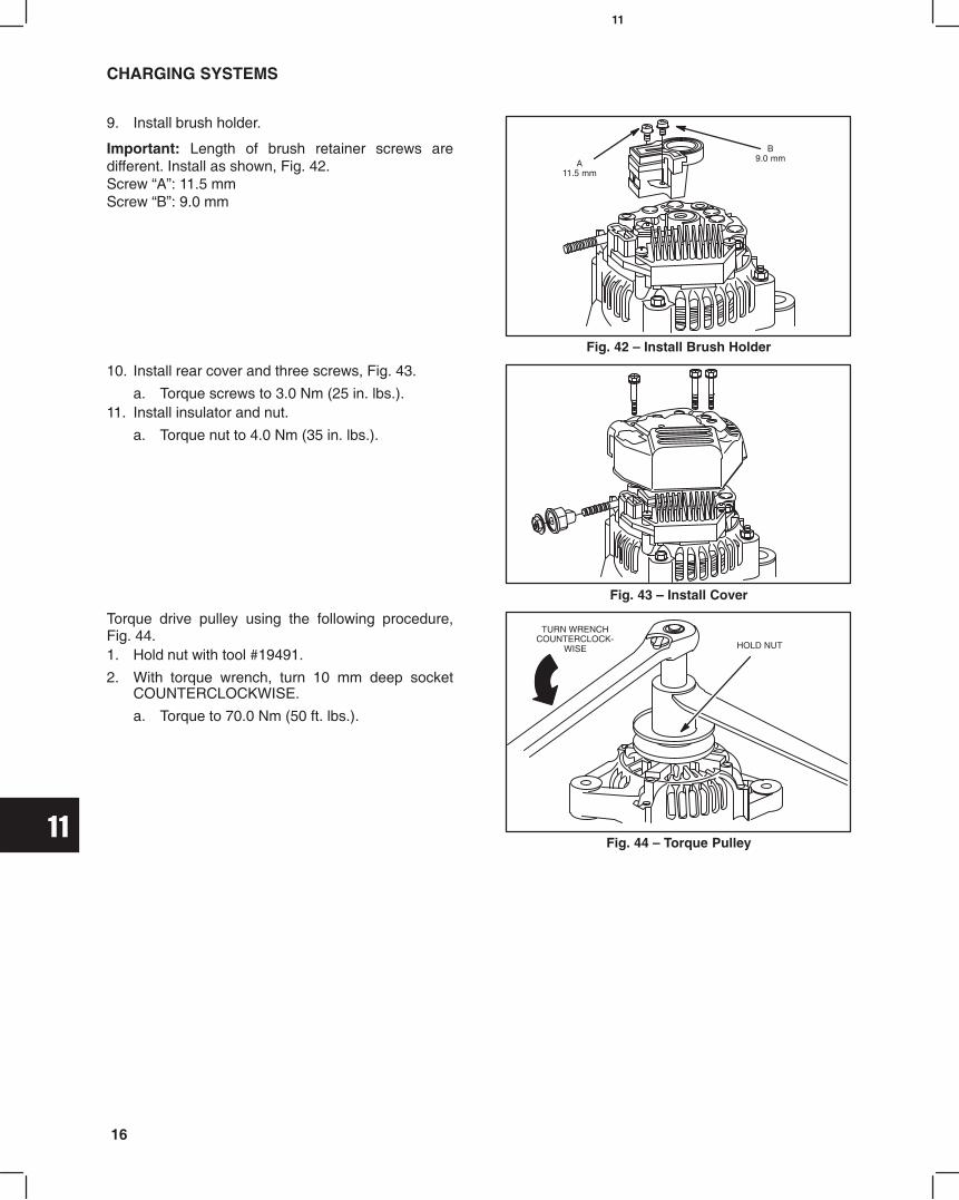
11
16
CHARGING SYSTEMS
9. Install brush holder.
Important: Length of brush retainer screws aredifferent. Install as shown, Fig. 42.Screw A: 11.5 mmScrew B: 9.0 mm
Fig. 42 Install Brush Holder
A11.5 mm
B9.0 mm
10. Install rear cover and three screws, Fig. 43.
a. Torque screws to 3.0 Nm (25 in. lbs.).11. Install insulator and nut.
a. Torque nut to 4.0 Nm (35 in. lbs.).
Fig. 43 Install Cover
Torque drive pulley using the following procedure,Fig. 44.1. Hold nut with tool #19491.
2. With torque wrench, turn 10 mm deep socketCOUNTERCLOCKWISE.
a. Torque to 70.0 Nm (50 ft. lbs.).
Fig. 44 Torque Pulley
TURN WRENCHCOUNTERCLOCK-
WISE HOLD NUT

11
17
STARTER SYSTEM
Fig. 45 1.0 Kw (Standard) Fig. 46 1.2 Kw (Optional)
IDENTIFICATION NUMBER IDENTIFICATION NUMBER
28100-87805 28100-87806
STARTER SYSTEM GENERAL INFORMATIONTwo different starter motors are used on Briggs & Stratton Daihatsu diesel engines. The standard motor is rated at 1.0Kw., Fig. 45. The optional starter is rated at 1.2 Kw., Fig. 46. The starters are identified by their identification numbers.The starters are similar enough that service procedures and specifications are the same. Where differences occur,they will be shown.
STARTER CURRENT DRAW TEST ALL(Starter Installed)Important: When making the starter current draw testmake sure that all parasitic load is removed from theengine and that engine has the correct viscosity oil.
Engine temperature should be at least 21° C (70° F).Make sure battery and solenoid connections are cleanand tight.
NOTE: Battery voltage must not be below 11.7volts.
Test EquipmentThe following equipment is required to test currentdraw of starter, Fig. 47.1. Digital multimeter, Tool #19464.
2. DC shunt, Tool #19468.
3. Two battery cables with alligator clips.
4. One jumper wire with alligator clips.
5. A fully charged 12 volt battery.
Fig. 47 Test Equipment
JUMPERWIRE
BATTERYCABLES
19390
19468
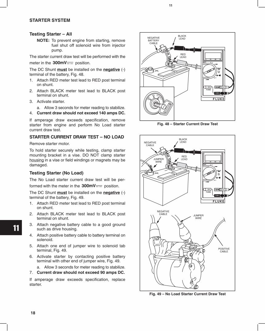
11
18
STARTER SYSTEM
Testing Starter AllNOTE: To prevent engine from starting, remove
fuel shut off solenoid wire from injectorpump.
The starter current draw test will be performed with the
meter in the position.
The DC Shunt must be installed on the negative (-)terminal of the battery, Fig. 48.1. Attach RED meter test lead to RED post terminal
on shunt.
2. Attach BLACK meter test lead to BLACK postterminal on shunt.
3. Activate starter.
a. Allow 3 seconds for meter reading to stabilize.4. Current draw should not exceed 140 amps DC.
If amperage draw exceeds specification, removestarter from engine and perform No Load startercurrent draw test.
Fig. 48 Starter Current Draw Test
NEGATIVEBATTERY
CABLE
BLACKLEAD
REDLEAD
STARTER CURRENT DRAW TEST NO LOADRemove starter motor.
To hold starter securely while testing, clamp startermounting bracket in a vise. DO NOT clamp starterhousing in a vise or field windings or magnets may bedamaged.
Testing Starter (No Load)The No Load starter current draw test will be per-
formed with the meter in the position.
The DC Shunt must be installed on the negative (-)terminal of the battery, Fig. 49.1. Attach RED meter test lead to RED post terminal
on shunt.
2. Attach BLACK meter test lead to BLACK postterminal on shunt.
3. Attach negative battery cable to a good groundsuch as drive housing.
4. Attach positive battery cable to battery terminal onsolenoid.
5. Attach one end of jumper wire to solenoid tabterminal, Fig. 49.
6. Activate starter by contacting positive batteryterminal with other end of jumper wire, Fig. 49.
a. Allow 3 seconds for meter reading to stabilize.7. Current draw should not exceed 90 amps DC.
If amperage draw exceeds specification, replacestarter.
Fig. 49 No Load Starter Current Draw Test
JUMPERWIRE
NEGATIVECABLE
BLACKLEAD
REDLEAD
NEGATIVECABLE JUMPER
WIRE
POSITIVECABLE

11
19
.
STARTER SYSTEM
STARTER SOLENOID
Test EquipmentThe starter solenoid test is performed with the starterremoved from the engine.
The following equipment is recommended to test thesolenoid.1. One battery cable with alligator clips. Fig. 50.
2. A jumper wire.
3. A fully charged 12 volt battery.Fig. 50 Test Equipment
JUMPERWIRE
BATTERYCABLE
Testing Starter Solenoid1. Attach one end of battery cable to negative battery
terminal and other end of cable to a good groundsuch as drive housing. Fig. 51.
2. Attach jumper wire to tab terminal on solenoid.
3. Activate solenoid by contacting positive batteryterminal with other end of jumper wire.
a. Pinion must move outward quickly (engage).4. Remove jumper wire from positive battery terminal.
a. Pinion must return quickly (disengage).
If pinion does not move, replace the solenoid.
Fig. 51 Testing Solenoid
JUMPERWIRE
DRIVE HOUSING
PINION AND DRIVE CLUTCH
DRIVE GEAR
RETAINER
ROLLER BEARINGS (5)
BALL
RETURN SPRING
SOLENOID
ARMATURE
STARTER HOUSING
BRUSH RETAINER
END CAP
3
4
5
6
7
2
8
12
11
10
9
1
2
3
45
6
78
9
10
11
12
1
EXPLODED VIEW OF STARTER TYPICAL

11
20
STARTER SYSTEM
Remove Solenoid1. Remove nut and field coil wire from stud terminal
on solenoid, Fig. 52.
Fig. 52 Removing Field Coil Wire
FIELD COIL WIRE
2. Remove through bolts and starter motor, Fig. 53.
DO NOT remove armature from starter housing or itwill be necessary to re-assemble brushes to armature.
Fig. 53 Removing Starter Motor
3. Remove two drive end cap screws. Hold starter invertical position with drive housing down andseparate solenoid housing from drive housing,Fig. 54. Note position of solenoid return springand ball.
NOTE: The solenoid must be replaced as anassembly.
Fig. 54 Removing Solenoid
DRIVEHOUSING
DOWN
Remove Pinion And Clutch Assembly1. Remove drive gear from bearing. Remove bearing
retainer and five roller bearings, Fig. 55.
2. Remove pinion and clutch assembly from drivehousing.
Fig. 55 Removing Pinion And Clutch
PINION AND CLUTCH
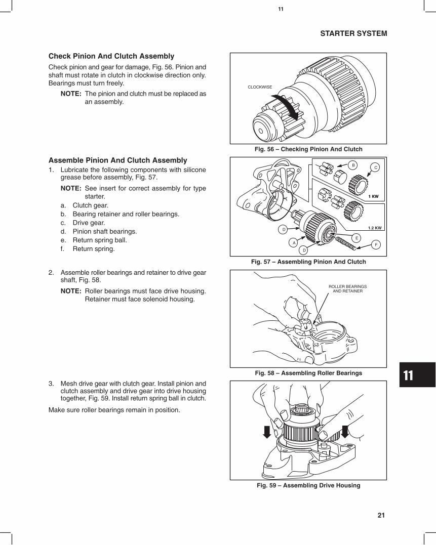
11
21
STARTER SYSTEM
Check Pinion And Clutch AssemblyCheck pinion and gear for damage, Fig. 56. Pinion andshaft must rotate in clutch in clockwise direction only.Bearings must turn freely.
NOTE: The pinion and clutch must be replaced asan assembly.
Fig. 56 Checking Pinion And Clutch
CLOCKWISE
Assemble Pinion And Clutch Assembly1. Lubricate the following components with silicone
grease before assembly, Fig. 57.
NOTE: See insert for correct assembly for typestarter.
a. Clutch gear.b. Bearing retainer and roller bearings.c. Drive gear.d. Pinion shaft bearings.e. Return spring ball.f. Return spring.
Fig. 57 Assembling Pinion And Clutch
E
F
D
A
BC
D
1 KW
1.2 KW
1 KW
2. Assemble roller bearings and retainer to drive gearshaft, Fig. 58.
NOTE: Roller bearings must face drive housing.Retainer must face solenoid housing.
Fig. 58 Assembling Roller Bearings
ROLLER BEARINGSAND RETAINER
3. Mesh drive gear with clutch gear. Install pinion andclutch assembly and drive gear into drive housingtogether, Fig. 59. Install return spring ball in clutch.
Make sure roller bearings remain in position.
Fig. 59 Assembling Drive Housing

11
22
STARTER SYSTEM
Install Solenoid1. Insert return spring into solenoid plunger.
2. Align pilot hole in solenoid with drive gear shaftand assemble solenoid to drive housing, Fig. 60.
a. Torque screws to 9.0 Nm (80 in. lbs.).
Fig. 60 Installing Solenoid
DRIVEHOUSING
DOWN
3. Assemble starter motor to drive housing. Align tabon starter with notch in drive housing, Fig. 61.
a. Torque screws to 9.0 Nm (80 in. lbs.).4. Install field coil wire.
a. Torque nut to 8 Nm (70 in. lbs.).
Fig. 61 Installing Starter Motor
Replace Solenoid Plunger And ContactsPlace starter in a vise with cover plate up.1. Remove three screws and cover plate.
a. Discard gasket.2. Remove plunger and spring.
Fig. 62 Remove Plunger
3. Replace contacts if burned or worn.
Note: Contacts and plunger must be replacedas an assembly.
4. Measure thickness of contact plates with calipers.
Reject Dimension: 0.9 mm (0.035).
Fig. 63 Checking Contacts
WEAR
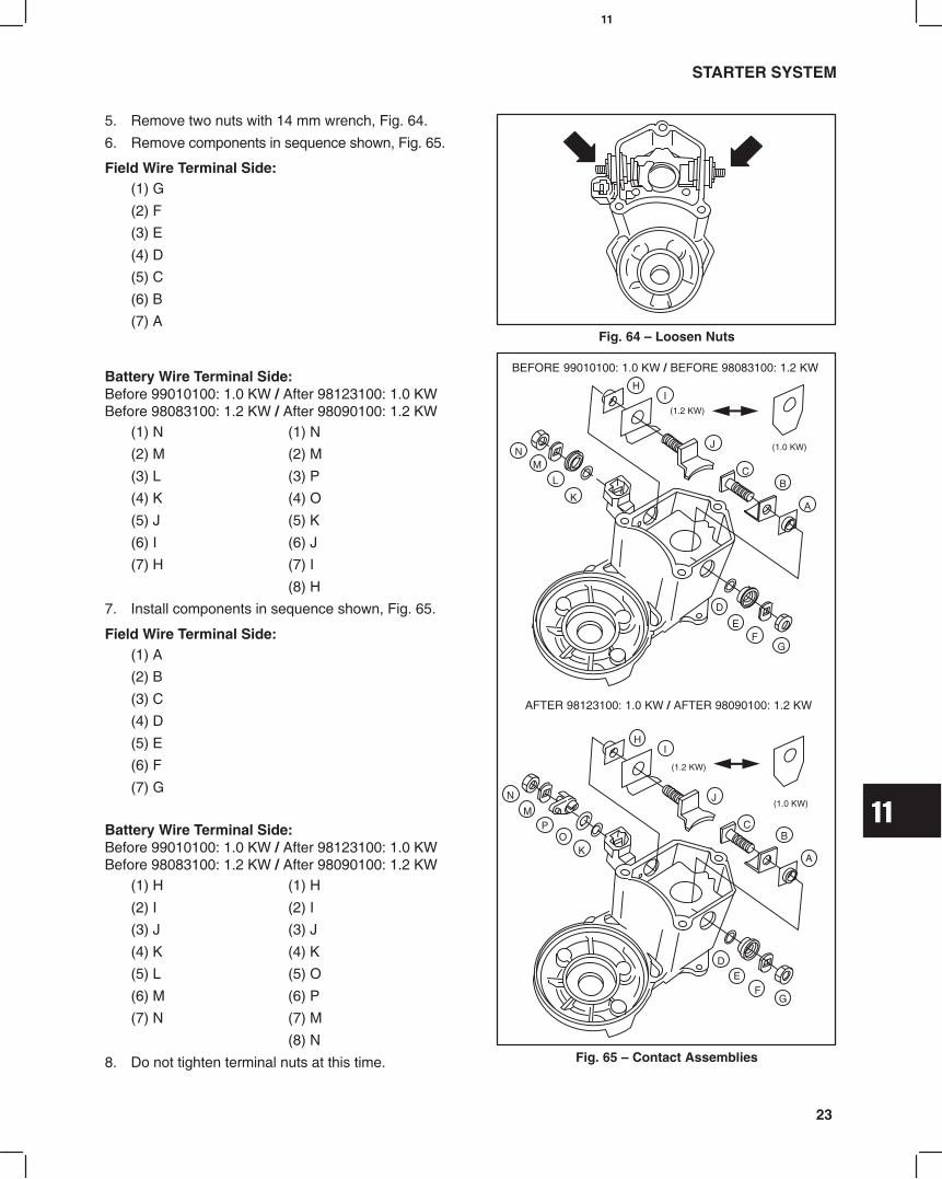
11
23
STARTER SYSTEM
5. Remove two nuts with 14 mm wrench, Fig. 64.
6. Remove components in sequence shown, Fig. 65.
Field Wire Terminal Side:(1) G
(2) F
(3) E
(4) D
(5) C
(6) B
(7) AFig. 64 Loosen Nuts
Battery Wire Terminal Side:Before 99010100: 1.0 KW / After 98123100: 1.0 KWBefore 98083100: 1.2 KW / After 98090100: 1.2 KW
(1) N (1) N
(2) M (2) M
(3) L (3) P
(4) K (4) O
(5) J (5) K
(6) I (6) J
(7) H (7) I
(8) H
7. Install components in sequence shown, Fig. 65.
Field Wire Terminal Side:(1) A
(2) B
(3) C
(4) D
(5) E
(6) F
(7) G
Battery Wire Terminal Side:Before 99010100: 1.0 KW / After 98123100: 1.0 KWBefore 98083100: 1.2 KW / After 98090100: 1.2 KW
(1) H (1) H
(2) I (2) I
(3) J (3) J
(4) K (4) K
(5) L (5) O
(6) M (6) P
(7) N (7) M
(8) N
8. Do not tighten terminal nuts at this time. Fig. 65 Contact Assemblies
BEFORE 99010100: 1.0 KW / BEFORE 98083100: 1.2 KW
AFTER 98123100: 1.0 KW / AFTER 98090100: 1.2 KW
A
BC
D
EF
G
HI
J
K
L
MN
(1.2 KW)
(1.0 KW)
A
BC
D
EF
G
HI
J
OP
M
N
(1.2 KW)
(1.0 KW)
K

11
24
STARTER SYSTEM
9. Install new plunger and spring.
10. Place bearing driver, Tool #19422 on plunger andcompress plunger to end of travel. Maintainpressure.
a. Torque nuts to 17 Nm (150 in. lbs.).Note: This provides proper contact alignment
with plunger and contact plates.11. Clean contact plates and plunger contacts.
12. Install cover plate with new gasket.
a. Torque screws to 4 Nm (35 in. lbs.).
Fig. 66 Aligning Contact Plates
DISASSEMBLE STARTER MOTOR1. Remove starter motor from drive housing.
2. Remove screws and end cap.
3. Remove armature from motor housing, Fig. 67.
If armature drive splines or armature bearings aredamaged or worn, replace armature.
Fig. 67 Disassemble Starter Motor
Inspect Armature CommutatorThe armature commutator may be cleaned with finesandpaper. DO NOT use emery cloth. Commutatormay be machined to no less than 29.0 mm (1.142),Fig. 68.
NOTE: Minimum depth of slots betweencommutator bars after machining is 0.2mm (.008).
The armature should be checked for shorts with agrowler.
Fig. 68 Commutator Specifications
29.0 mm
Inspect BrushesMinimum brush dimension is shown below Fig. 69.
1.0 KW Starter: 9 mm (.350).1.2 KW Starter: 10 mm (.400).
If brushes are worn less than specification, replace asfollows.1.0 KW Starter: Replace brush retainer and brushes
on starter housing.1.2 KW Starter: Starter housing and brush retainer
must be replaced as an assembly. Fig. 69 Minimum Brush Dimension
1.2 KW: 10 mm
1.0 KW: 9 mm

11
25
STARTER SYSTEM
Use digital multimeter and check for continuitybetween field coil wire and brushes shown, Fig. 70.
The following test will be made with the meter in the
Diode Test Position .1. Attach either meter test lead to field coil wire.
2. Contact first one positive brush, then oppositebrush with other test lead as shown.
a. Meter should make continuous tone(continuity).
b. If meter does not make a tone, (no continuity)replace starter housing.
Fig. 70 Checking Brushes
3. Attach either test lead to brush retainer, Fig. 71.
4. Contact first one negative brush, then oppositebrush with other test lead as shown.
a. Meter should make continuous tone(continuity).
b. If meter does not make a tone, (no continuity)replace brush retainer.
Fig. 71 Checking Brushes
Replace Brushes 1.0 KW Starter1. Cut off brush lead wires at terminals as shown.
2. Use a fine file and carefully remove remaining leadwire from terminals.
L: 2.3 2.7 mm (0.090 0.106)W: 6.5 7.5 mm (0.255 0.295)
Fig. 72 Clean Terminals
L
W
BRUSH
LEAD WIRE
CUT
3. Crimp replacement brushes over terminals so thatwires face in counterclockwise direction.
4. Solder brush lead wires to terminals.
5. Insert brushes into brush retainer.
Fig. 73 Install Brushes
COUNTERCLOCKWISE
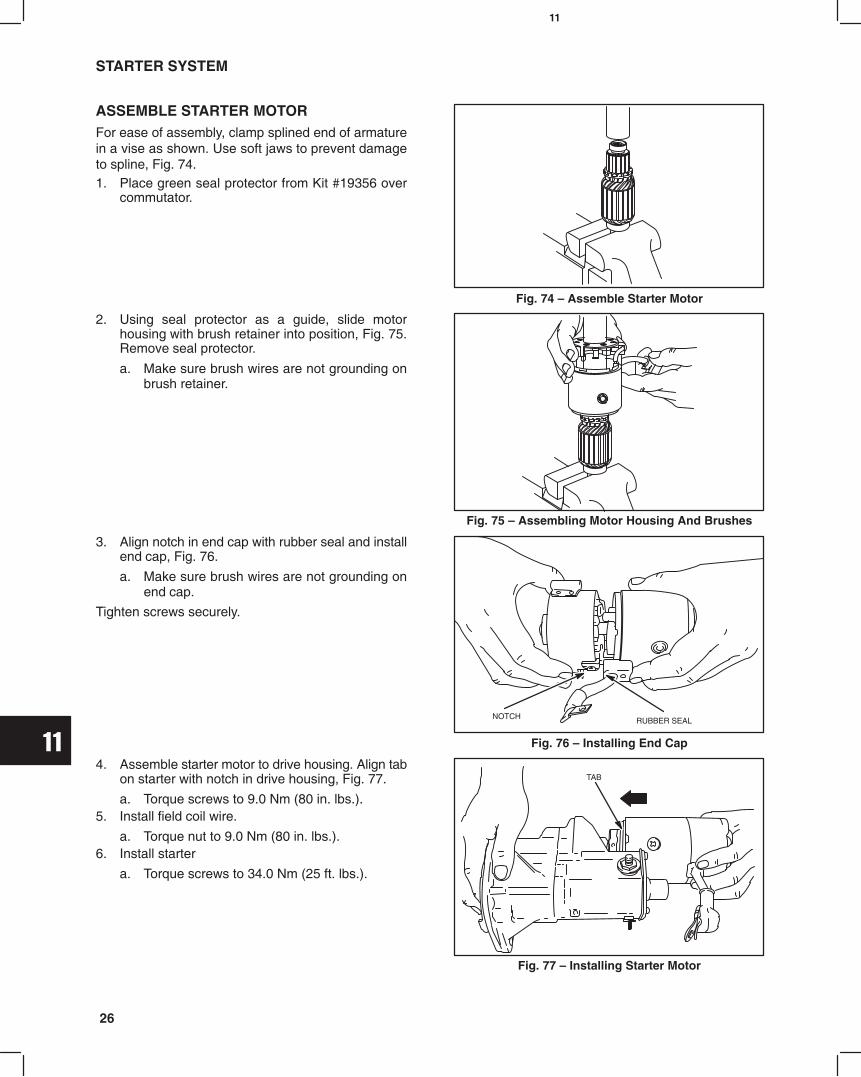
11
26
STARTER SYSTEM
ASSEMBLE STARTER MOTORFor ease of assembly, clamp splined end of armaturein a vise as shown. Use soft jaws to prevent damageto spline, Fig. 74.1. Place green seal protector from Kit #19356 over
commutator.
Fig. 74 Assemble Starter Motor
2. Using seal protector as a guide, slide motorhousing with brush retainer into position, Fig. 75.Remove seal protector.
a. Make sure brush wires are not grounding onbrush retainer.
Fig. 75 Assembling Motor Housing And Brushes
3. Align notch in end cap with rubber seal and installend cap, Fig. 76.
a. Make sure brush wires are not grounding onend cap.
Tighten screws securely.
Fig. 76 Installing End Cap
RUBBER SEALNOTCH
4. Assemble starter motor to drive housing. Align tabon starter with notch in drive housing, Fig. 77.
a. Torque screws to 9.0 Nm (80 in. lbs.).5. Install field coil wire.
a. Torque nut to 9.0 Nm (80 in. lbs.).6. Install starter
a. Torque screws to 34.0 Nm (25 ft. lbs.).
Fig. 77 Installing Starter Motor
TAB

11
27
STARTER SYSTEM
Fig. 78
Wiring Diagram 14 Amp Alternator (Typical)493625 Keyswitch With Fixed Preheat Timer and Glow Relay
12 VOLT BATTERY
REGULATORRECTIFIER
STARTER MOTOR
BLACK
LT. BLUE
CHARGE INDICATORLIGHT
RED
GREENYELLOW
SOLENOID
FUEL FILTER
WATER INDICATORLIGHT
INJECTION PUMP
GLOW PLUGS
GLOWLIGHT
PREHEATING TIMER
GLOWRELAYKEYSWITCH
LIGHTBLUE
GREEN YELLOW
BLACK
RED
LIGHTBLUE
Regulator Connector
3 4
5
6
7
1
2
8
2
4
5
ACCESSORY & PREHEAT TIMER
SOLENOID & PREHEAT TIMER
BATTERY
KEYSWITCHTERMINAL FUNCTION
6
3
5
4
2
1
NOTE: TERMINALS 1, 3, 6 NOT USED
PART NO.493625
14 AMPALTERNATOR

11
28
STARTER SYSTEM
40 AMPALTERNATOR
Fig. 79
12 VOLT BATTERY
STARTER MOTOR
SOLENOID
INJECTION PUMP
GLOWLIGHT
PREHEATING TIMER
GLOWRELAY
FUEL FILTER
WATER INDICATORLIGHT
CHARGE INDICATORLIGHT
BTERMINAL
IGTERMINAL
Wiring Diagram 40 Amp Alternator (Typical)493625 Keyswitch With Fixed Preheat Timer and Glow Relay
3 4
5
6
7
1
2
8
IGTERMINAL
LTERMINAL
BTERMINAL
LTERMINAL
GLOW PLUGS
KEYSWITCH
2
4
5
ACCESSORY & PREHEAT TIMER
SOLENOID & PREHEAT TIMER
BATTERY
KEYSWITCHTERMINAL FUNCTION
6
3
5
4
2
1
NOTE: TERMINALS 1, 3, 6 NOT USED
PART NO.493625

11
29
STARTER SYSTEM
14 AMPALTERNATOR
Fig. 80
SG1
G2
M
B
B
12 VOLT BATTERY
REGULATORRECTIFIER
STARTER MOTOR
BLACK
LT. BLUE
CHARGE INDICATORLIGHT
RED
GREENYELLOW
SOLENOID
FUEL FILTER
WATER INDICATORLIGHT
INJECTION PUMP
GLOW PLUGS
GLOWLIGHT
Wiring Diagram 14 Amp Alternator (Typical)825129 Keyswitch Manual Preheat
LIGHTBLUE
GREEN YELLOW
BLACK
RED
LIGHTBLUE
Regulator Connector
B
S
G1
G2
M
BATTERY
SOLENOID
GLOW PLUG (PREHEAT)
GLOW PLUG (CRANKING)
ACCESSORY
KEYSWITCHTERMINAL FUNCTION
KEYSWITCHPART NO.
825129
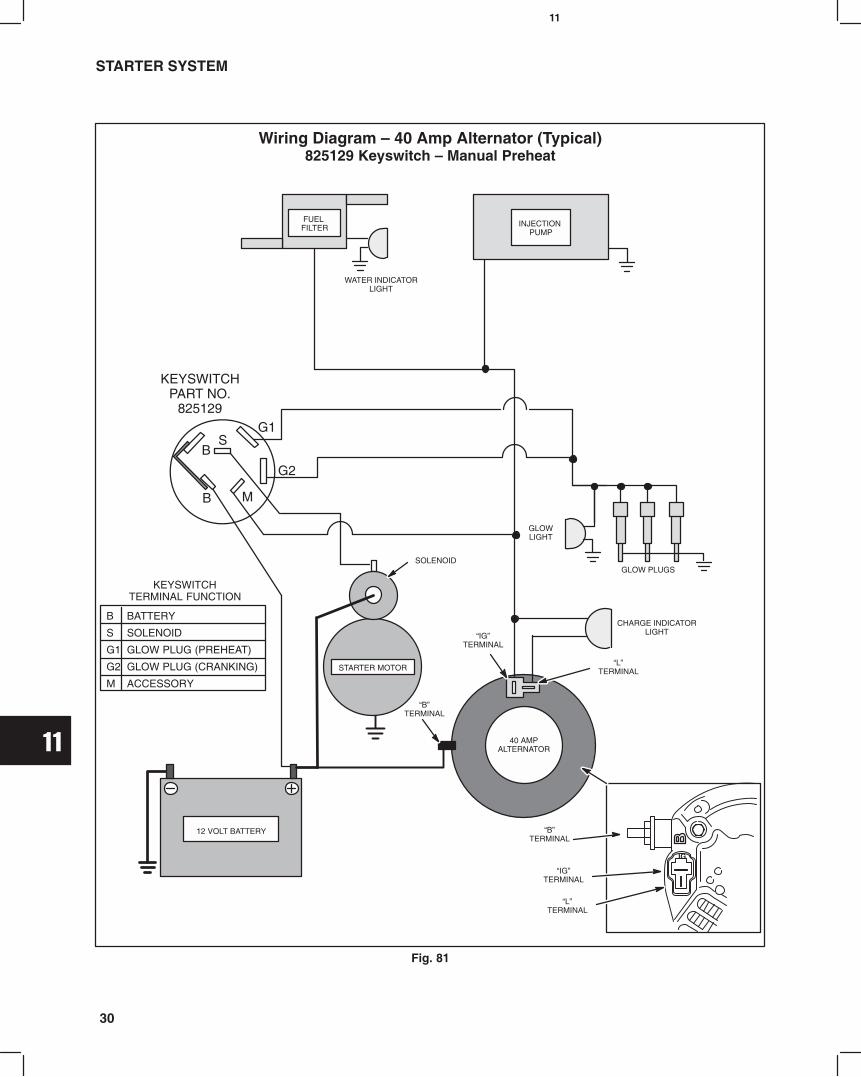
11
30
STARTER SYSTEM
40 AMPALTERNATOR
Fig. 81
Wiring Diagram 40 Amp Alternator (Typical)825129 Keyswitch Manual Preheat
12 VOLT BATTERY
STARTER MOTOR
SOLENOID
INJECTION PUMP
GLOWLIGHT
FUEL FILTER
WATER INDICATORLIGHT
CHARGE INDICATORLIGHT
BTERMINAL
IGTERMINAL
IGTERMINAL
LTERMINAL
BTERMINAL
LTERMINAL
GLOW PLUGS
B
S
G1
G2
M
BATTERY
SOLENOID
GLOW PLUG (PREHEAT)
GLOW PLUG (CRANKING)
ACCESSORY
KEYSWITCHTERMINAL FUNCTION
SG1
G2
M
B
B
KEYSWITCHPART NO.
825129
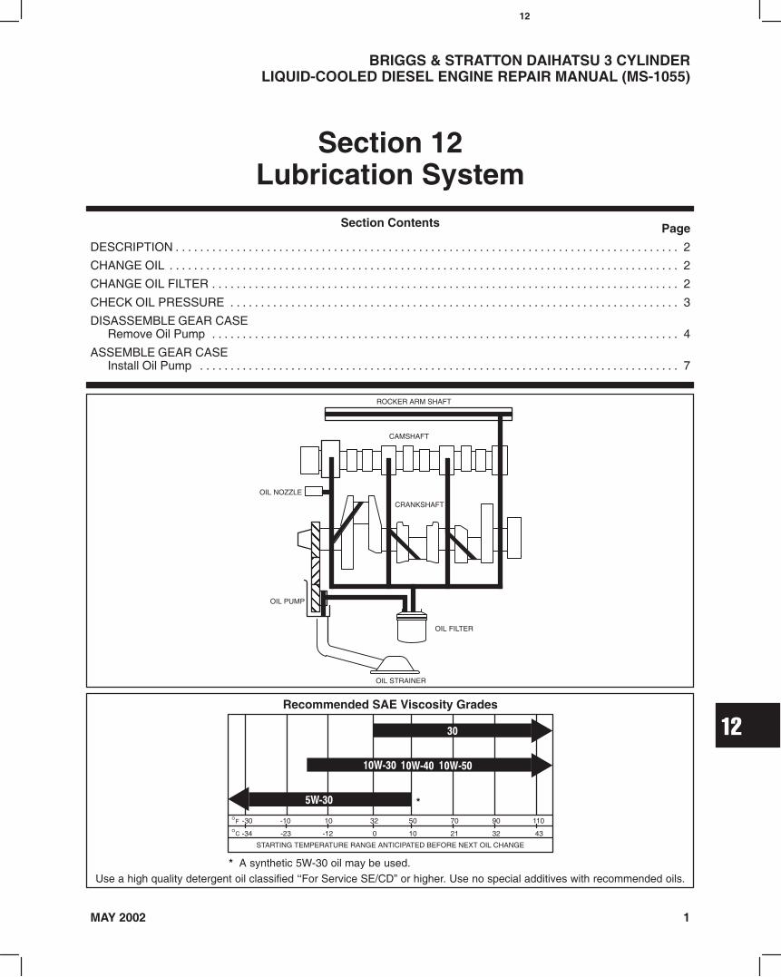
12
1MAY 2002
BRIGGS & STRATTON DAIHATSU 3 CYLINDERLIQUID-COOLED DIESEL ENGINE REPAIR MANUAL (MS-1055)
Section 12Lubrication System
Page
DESCRIPTION 2. . . . . . . . . . . . . . . . . . . . . . . . . . . . . . . . . . . . . . . . . . . . . . . . . . . . . . . . . . . . . . . . . . . . . . . . . . . . . . . . . . .
CHANGE OIL 2. . . . . . . . . . . . . . . . . . . . . . . . . . . . . . . . . . . . . . . . . . . . . . . . . . . . . . . . . . . . . . . . . . . . . . . . . . . . . . . . . . . .
CHANGE OIL FILTER 2. . . . . . . . . . . . . . . . . . . . . . . . . . . . . . . . . . . . . . . . . . . . . . . . . . . . . . . . . . . . . . . . . . . . . . . . . . . . .
CHECK OIL PRESSURE 3. . . . . . . . . . . . . . . . . . . . . . . . . . . . . . . . . . . . . . . . . . . . . . . . . . . . . . . . . . . . . . . . . . . . . . . . . .
DISASSEMBLE GEAR CASERemove Oil Pump 4. . . . . . . . . . . . . . . . . . . . . . . . . . . . . . . . . . . . . . . . . . . . . . . . . . . . . . . . . . . . . . . . . . . . . . . . . . . . .
ASSEMBLE GEAR CASEInstall Oil Pump 7. . . . . . . . . . . . . . . . . . . . . . . . . . . . . . . . . . . . . . . . . . . . . . . . . . . . . . . . . . . . . . . . . . . . . . . . . . . . . . .
Section Contents
Recommended SAE Viscosity Grades
°C -34
STARTING TEMPERATURE RANGE ANTICIPATED BEFORE NEXT OIL CHANGE
°F -30 -10 10 50 70 90 110
-23 -12 0 10 21 32 43
32
*
* A synthetic 5W-30 oil may be used.Use a high quality detergent oil classified For Service SE/CD or higher. Use no special additives with recommended oils.
ROCKER ARM SHAFT
CAMSHAFT
OIL FILTER
OIL PUMP
CRANKSHAFT
OIL STRAINER
OIL NOZZLE
ÇÇÇÇÇÇÉÉÉÉÇÇÇÇÇÇ

12
2
LUBRICATION SYSTEM
DESCRIPTIONBriggs & Stratton Daihatsu gasoline and diesel engines use a full pressure lubrication system with an oil filter.The gear driven oil pump draws oil from a screened oil pickup in the oil pan and pumps the oil through the oil filter.The filtered oil flows through oil galleries in the cylinder block and is distributed to the main bearings, connecting rodbearings, camshaft bearings and rocker arm shaft.A pressure relief valve limits the maximum oil pressure in the system.
CHANGE OILChange oil and filter after first 50 hours of operation.Thereafter, change oil every 100 hours of operation.Change oil filter every 200 hours of operation.Change oil and filter more often if engine is operatedin dusty or dirty conditions or if engine is operatedunder heavy loads or high ambient air temperatures.Remove oil drain plug and drain oil while engine is stillwarm, Fig. 1. Check oil drain plug gasket and replace ifnecessary. Install and torque drain plug to 24.8 Nm(220 in. lbs.).
Fig. 1 Oil Drain Plug
DRAIN PLUG
OIL FILTER
Remove oil fill cap and refill with oil of recommendedgrade and viscosity. See Page 1.Oil Capacity: 3.3 liters (3.5 quarts)Fill to FULL mark on dipstick.
Fig. 2 Oil Fill Cap
OIL FILL CAP
CHANGE OIL FILTERChange oil filter every 200 hours of operation.Before installing new filter, lightly oil filter gasket withfresh clean engine oil.
NOTE: Hand tighten 1/2 turn after gasketcontacts mounting surface.
Fig. 3 Replacing Oil Filter
1/2 TURN

12
3
LUBRICATION SYSTEM
CHECK OIL PRESSURE1. Oil level should be between the LOW and FULL
marks on dipstick. If oil level is low, check for leaksand add to FULL mark.
Fig. 4 Oil Level
OIL LEVELSHOULD BEBETWEEN F
AND LMARKS ONDIPSTICK.
2. Remove oil pressure switch.3. Install oil pressure gauge.4. Start the engine and allow it to reach normal
operating temperature.5. Check oil pressure at 3000 RPM.Oil Pressure: 2.0 ~ 5.0 Bar (28 ~ 70 psi)See charts below for troubleshooting guide.
Low Oil PressureEngine RPM Too LowWrong Viscosity or Diluted OilLow Oil LevelBroken Pressure Relief Spring
Missing Pressure Relief PlungerWorn BearingsDamaged Or Defective Oil Pump
Fig. 5 Checking Oil Pressure
OIL PRESSURESWITCH
High Oil Pressure
Wrong Viscosity Oil
Plugged Oil Galleries
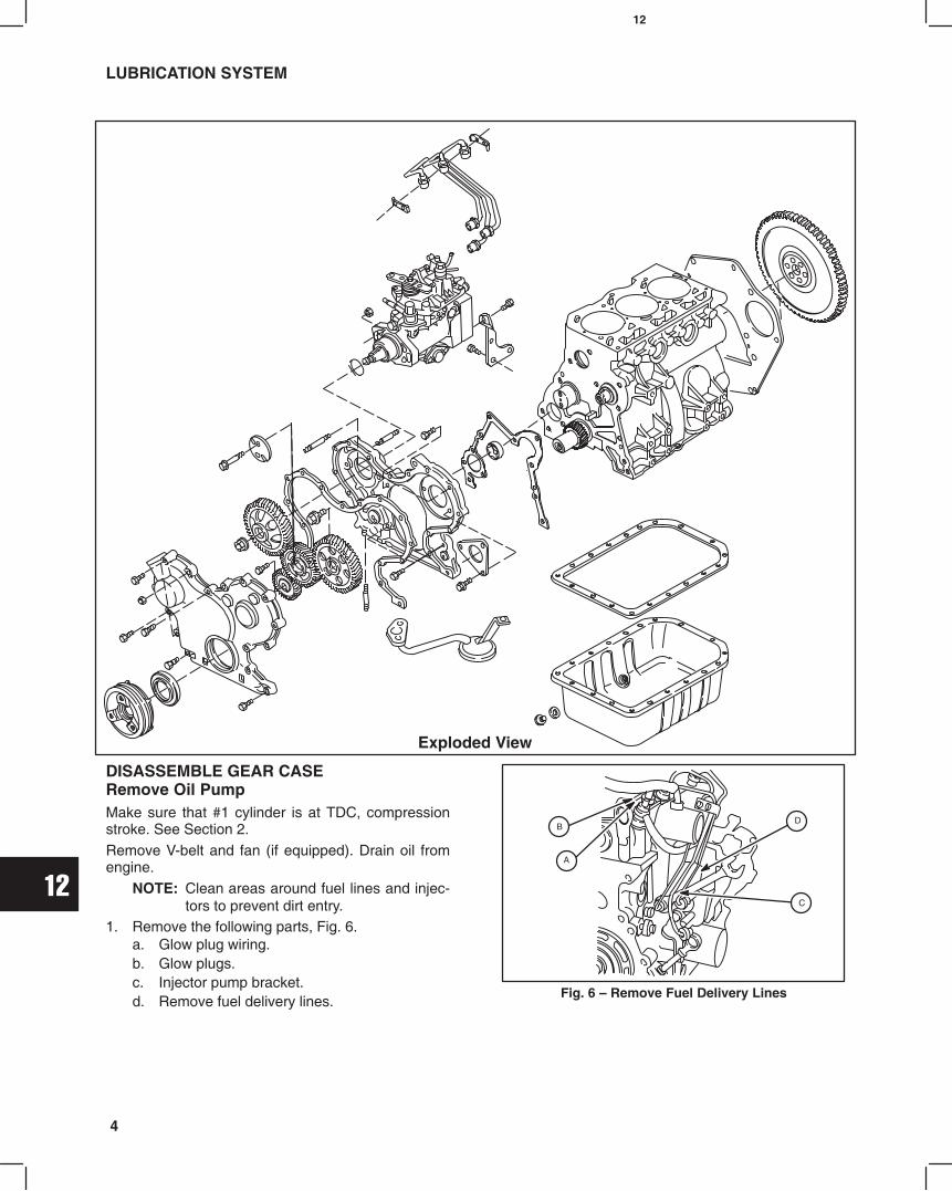
12
4
LUBRICATION SYSTEM
Exploded View
DISASSEMBLE GEAR CASERemove Oil PumpMake sure that #1 cylinder is at TDC, compressionstroke. See Section 2.Remove V-belt and fan (if equipped). Drain oil fromengine.
NOTE: Clean areas around fuel lines and injec-tors to prevent dirt entry.
1. Remove the following parts, Fig. 6.a. Glow plug wiring.b. Glow plugs.c. Injector pump bracket.d. Remove fuel delivery lines.
Fig. 6 Remove Fuel Delivery Lines
B
A
C
D

12
5
LUBRICATION SYSTEM
2. Remove oil pan screws and nuts.a. Remove oil pan and discard gasket.b. Remove oil pick-up tube and strainer. Discard
gasket, Fig. 7.
Fig. 7 Removing Oil Pan
OIL PICK-UPTUBE
3. Remove bell housing adapter screw if equipped.and install flywheel holder, Tool #19418.
LEAVE TOOL INSTALLED.a. Remove crankshaft pulley using Tool # 19420,
Fig. 8.
Fig. 8 Removing Crankshaft Pulley
FLYWHEELHOLDER
4. Remove timing gear cover, Fig. 9.a. Discard timing gear cover gasket.
Fig. 9 Removing Timing Gear Cover
5. Remove the following parts, Fig. 10.a. Camshaft timing gear.b. Oil pump gear.c. Injector pump nut.d. Idler gear.
Fig. 10 Removing Gears
C A
D
B

12
6
LUBRICATION SYSTEM
6. Remove injector pump timing gear with a threejaw puller, Fig. 11.a. Remove 2 nuts and injector pump. Discard
O-ring.
Fig. 11 Removing Injector Pump
ORING
7. Remove parts in sequence shown, Fig. 12.a. Remove 3 screws and camshaft retainer.b. Remove remaining 5 screws.c. Remove timing gear case and discard gasket.
Fig. 12 Removing Timing Gear Case
AB
B
8. Inspect rotors for wear or damage, Fig. 13.NOTE: If pump rotors are worn or damaged,
replace the gear case.
Fig. 13 Inspect Rotors
OIL PUMPROTORS
9. Remove and check pressure relief valveassembly, Fig. 14.a. Make sure plunger has no nicks or burrs.b. Check pressure relief valve spring free length.
10. Spring free length: 35.5 mm ± (1.400 ± .040)
Fig. 14 Checking Pressure Relief Valve
SCREW
SPRING
WASHER
PLUNGER
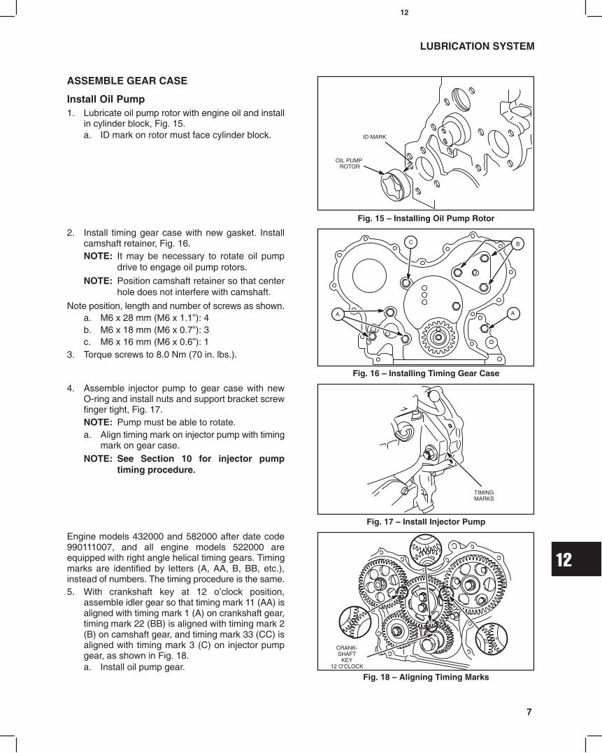
12
7
LUBRICATION SYSTEM
ASSEMBLE GEAR CASE
Install Oil Pump1. Lubricate oil pump rotor with engine oil and install
in cylinder block, Fig. 15.a. ID mark on rotor must face cylinder block.
Fig. 15 Installing Oil Pump Rotor
OIL PUMP ROTOR
ID MARK
2. Install timing gear case with new gasket. Installcamshaft retainer, Fig. 16.NOTE: It may be necessary to rotate oil pump
drive to engage oil pump rotors.
NOTE: Position camshaft retainer so that centerhole does not interfere with camshaft.
Note position, length and number of screws as shown.a. M6 x 28 mm (M6 x 1.1): 4b. M6 x 18 mm (M6 x 0.7): 3c. M6 x 16 mm (M6 x 0.6): 1
3. Torque screws to 8.0 Nm (70 in. lbs.).
Fig. 16 Installing Timing Gear Case
B
A
C
A
4. Assemble injector pump to gear case with newO-ring and install nuts and support bracket screwfinger tight, Fig. 17.NOTE: Pump must be able to rotate.a. Align timing mark on injector pump with timing
mark on gear case.NOTE: See Section 10 for injector pump
timing procedure.
Fig. 17 Install Injector Pump
TIMINGMARKS
Engine models 432000 and 582000 after date code990111007, and all engine models 522000 areequipped with right angle helical timing gears. Timingmarks are identified by letters (A, AA, B, BB, etc.),instead of numbers. The timing procedure is the same.5. With crankshaft key at 12 oclock position,
assemble idler gear so that timing mark 11 (AA) isaligned with timing mark 1 (A) on crankshaft gear,timing mark 22 (BB) is aligned with timing mark 2(B) on camshaft gear, and timing mark 33 (CC) isaligned with timing mark 3 (C) on injector pumpgear, as shown in Fig. 18.a. Install oil pump gear.
Fig. 18 Aligning Timing Marks
CRANK-SHAFT
KEY12 OCLOCK

12
8
LUBRICATION SYSTEM
6. Torque screws as shown, Fig. 19.a. Camshaft gear:
41.0 Nm (30 ft. lbs.)b. Idler gear:
25.0 Nm (220 in. lbs.)c. Injector pump gear:
61.0 Nm (45 ft. lbs.)d. Oil pump gear:
19.0 Nm (170 in. lbs.)
Fig. 19 Torque Screws
C
D
B
A
7. Install timing gear cover with new gasket. Noteposition, length and number of screws as shown,Fig. 20.a. M6 x 55 mm (M6 x 2.5): 3b. M6 x 45 mm (M6 x 2.1): 2c. M6 x 30 mm (M6 x 1.1): 9d. M6 nut: 2
8. Torque screws and nuts to 8.0 Nm (70 in. lbs.).
Fig. 20 Installing Timing Gear Cover
B
CA
A
B DCD
C
C
9. Install crankshaft pulley with timing mark at12 oclock position (#1 cylinder), Fig. 21.NOTE: Be sure alignment pin in crankshaft gear
is seated in hole in pulley.a. Torque screw to 88.0 Nm (65 ft. lbs.).b. Remove flywheel holder.
Fig. 21 Installing Crankshaft Pulley10. Install oil pick-up tube and strainer with new
gasket. Torque to 8.0 Nm (70 in. lbs.).a. Apply a small bead of Permatex No. 2 or
similar sealant to crankcase areas shown,Fig. 22.
b. Install oil pan with new gasket.c. Torque screws and nuts to 8.0 Nm (70 in. lbs.).
Fig. 22 Installing Oil Pan
SEALANT

12
9
LUBRICATION SYSTEM
11. Install Glow plugs, wiring and fuel delivery lines.a. Torque glow plugs to 17.0 Nm (150 in. lbs.).b. Torque fuel delivery lines to 25.0 Nm
(220 in. lbs.), Fig. 23.
Fig. 23 Installing Fuel Delivery Lines
12. Install V-belt, Fig. 24.
13. Install alternator bolts A and B .
Belt deflection limit is 1012 mm/10 kg(3/81/2 in/22 lbs.).
a. Torque bolt A to 19.0 Nm (170 in. lbs.).
b. Torque bolt B to 61.0 Nm (45 ft. lbs.).
Fig. 24 Adjusting V-belt
3/8 1/2 Inch(10 12 mm)
BELT MOVEMENT B
A
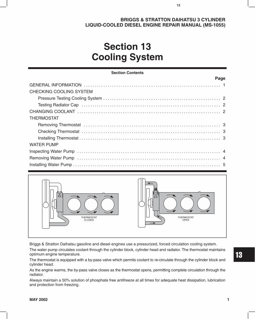
13
1MAY 2002
Section ContentsPage
GENERAL INFORMATION 1. . . . . . . . . . . . . . . . . . . . . . . . . . . . . . . . . . . . . . . . . . . . . . . . . . . . . . . . . . . . . . .
CHECKING COOLING SYSTEM
Pressure Testing Cooling System 2. . . . . . . . . . . . . . . . . . . . . . . . . . . . . . . . . . . . . . . . . . . . . . . . . . . . . .
Testing Radiator Cap 2. . . . . . . . . . . . . . . . . . . . . . . . . . . . . . . . . . . . . . . . . . . . . . . . . . . . . . . . . . . . . . . .
CHANGING COOLANT 2. . . . . . . . . . . . . . . . . . . . . . . . . . . . . . . . . . . . . . . . . . . . . . . . . . . . . . . . . . . . . . . . . .
THERMOSTAT
Removing Thermostat 3. . . . . . . . . . . . . . . . . . . . . . . . . . . . . . . . . . . . . . . . . . . . . . . . . . . . . . . . . . . . . . .
Checking Thermostat 3. . . . . . . . . . . . . . . . . . . . . . . . . . . . . . . . . . . . . . . . . . . . . . . . . . . . . . . . . . . . . . . .
Installing Thermostat 3. . . . . . . . . . . . . . . . . . . . . . . . . . . . . . . . . . . . . . . . . . . . . . . . . . . . . . . . . . . . . . . . .
WATER PUMP
Inspecting Water Pump 4. . . . . . . . . . . . . . . . . . . . . . . . . . . . . . . . . . . . . . . . . . . . . . . . . . . . . . . . . . . . . . . . . .
Removing Water Pump 4. . . . . . . . . . . . . . . . . . . . . . . . . . . . . . . . . . . . . . . . . . . . . . . . . . . . . . . . . . . . . . . . . .
Installing Water Pump 5. . . . . . . . . . . . . . . . . . . . . . . . . . . . . . . . . . . . . . . . . . . . . . . . . . . . . . . . . . . . . . . . . . . .
BRIGGS & STRATTON DAIHATSU 3 CYLINDERLIQUID-COOLED DIESEL ENGINE REPAIR MANUAL (MS-1055)
Section 13Cooling System
Briggs & Stratton Daihatsu gasoline and diesel engines use a pressurized, forced circulation cooling system.The water pump circulates coolant through the cylinder block, cylinder head and radiator. The thermostat maintainsoptimum engine temperature.The thermostat is equipped with a by-pass valve which permits coolant to re-circulate through the cylinder block andcylinder head.As the engine warms, the by-pass valve closes as the thermostat opens, permitting complete circulation through theradiator.Always maintain a 50% solution of phosphate free antifreeze at all times for adequate heat dissipation, lubricationand protection from freezing.
THERMOSTATCLOSED
THERMOSTATOPEN
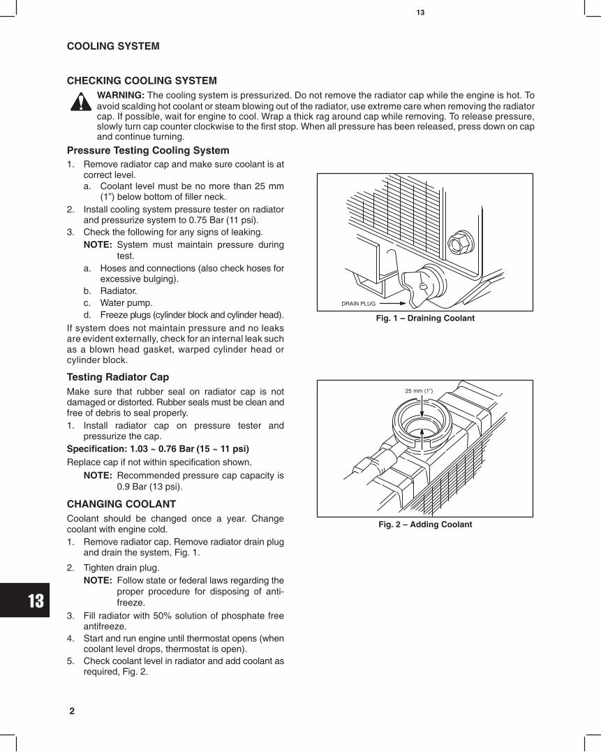
13
2
COOLING SYSTEM
CHECKING COOLING SYSTEMWARNING: The cooling system is pressurized. Do not remove the radiator cap while the engine is hot. Toavoid scalding hot coolant or steam blowing out of the radiator, use extreme care when removing the radiatorcap. If possible, wait for engine to cool. Wrap a thick rag around cap while removing. To release pressure,slowly turn cap counter clockwise to the first stop. When all pressure has been released, press down on capand continue turning.
Pressure Testing Cooling System1. Remove radiator cap and make sure coolant is at
correct level.a. Coolant level must be no more than 25 mm
(1) below bottom of filler neck.2. Install cooling system pressure tester on radiator
and pressurize system to 0.75 Bar (11 psi).3. Check the following for any signs of leaking.
NOTE: System must maintain pressure duringtest.
a. Hoses and connections (also check hoses forexcessive bulging).
b. Radiator.c. Water pump.d. Freeze plugs (cylinder block and cylinder head).
If system does not maintain pressure and no leaksare evident externally, check for an internal leak suchas a blown head gasket, warped cylinder head orcylinder block.
Testing Radiator CapMake sure that rubber seal on radiator cap is notdamaged or distorted. Rubber seals must be clean andfree of debris to seal properly.1. Install radiator cap on pressure tester and
pressurize the cap.Specification: 1.03 ~ 0.76 Bar (15 ~ 11 psi)Replace cap if not within specification shown.
NOTE: Recommended pressure cap capacity is0.9 Bar (13 psi).
CHANGING COOLANTCoolant should be changed once a year. Changecoolant with engine cold.1. Remove radiator cap. Remove radiator drain plug
and drain the system, Fig. 1.
Fig. 1 Draining Coolant
DRAIN PLUG
Fig. 2 Adding Coolant
25 mm (1)
2. Tighten drain plug.NOTE: Follow state or federal laws regarding the
proper procedure for disposing of anti-freeze.
3. Fill radiator with 50% solution of phosphate freeantifreeze.
4. Start and run engine until thermostat opens (whencoolant level drops, thermostat is open).
5. Check coolant level in radiator and add coolant asrequired, Fig. 2.

13
3
COOLING SYSTEM
THERMOSTAT
Removing Thermostat Engine Cold1. Drain engine coolant.2. Remove screws and coolant outlet housing.3. Remove locating screw and thermostat, Fig. 3.4. Remove all traces of gasket material.
Fig. 3 Removing Thermostat
LOCATINGSCREW
COOLANTOUTLET
THERMOSTAT
Checking ThermostatA thermometer capable of reading 100° C (210° F) ormore is required.1. Check to make sure thermostat valve is fully closed.2. Immerse thermostat in water and heat water
gradually, Fig. 4.3. Note temperature when thermostat starts to open.
a. 81 ~ 84° C (178 ~ 183° F)4. Note temperature when thermostat is fully open.
a. 95° C (203° F)5. Remove thermostat from water and allow to cool.
a. Thermostat should close fully.
Fig. 4 Checking Thermostat
Installing Thermostat1. Insert thermostat in housing and install locating
screw, Fig. 5.2. Install coolant outlet housing with new gasket.3. Torque screws to 8.0 Nm (70 in. lbs.).Refill with coolant.
Fig. 5 Installing Thermostat
LOCATING SCREW
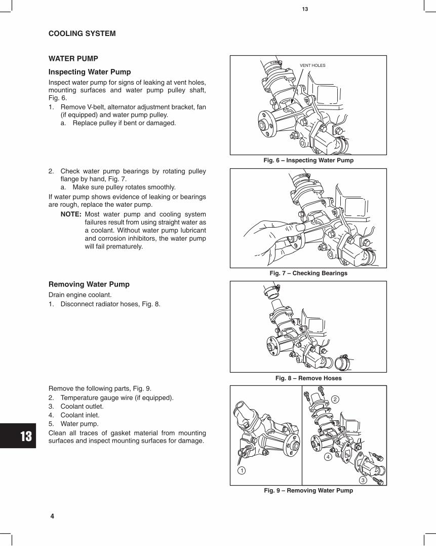
13
4
COOLING SYSTEM
WATER PUMP
Inspecting Water PumpInspect water pump for signs of leaking at vent holes,mounting surfaces and water pump pulley shaft,Fig. 6.1. Remove V-belt, alternator adjustment bracket, fan
(if equipped) and water pump pulley.a. Replace pulley if bent or damaged.
Fig. 6 Inspecting Water Pump
VENT HOLES
2. Check water pump bearings by rotating pulleyflange by hand, Fig. 7.a. Make sure pulley rotates smoothly.
If water pump shows evidence of leaking or bearingsare rough, replace the water pump.
NOTE: Most water pump and cooling systemfailures result from using straight water asa coolant. Without water pump lubricantand corrosion inhibitors, the water pumpwill fail prematurely.
Fig. 7 Checking Bearings
Removing Water PumpDrain engine coolant.1. Disconnect radiator hoses, Fig. 8.
Fig. 8 Remove Hoses
Remove the following parts, Fig. 9.2. Temperature gauge wire (if equipped).3. Coolant outlet.4. Coolant inlet.5. Water pump.Clean all traces of gasket material from mountingsurfaces and inspect mounting surfaces for damage.
Fig. 9 Removing Water Pump
3
4
1
2
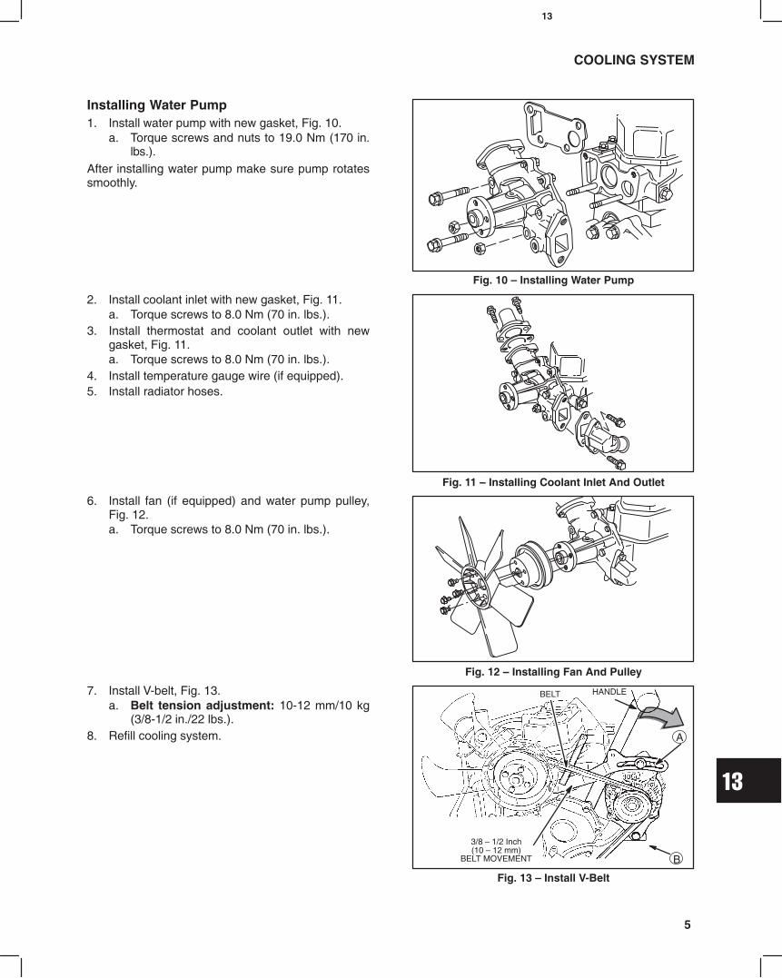
13
5
COOLING SYSTEM
Installing Water Pump1. Install water pump with new gasket, Fig. 10.
a. Torque screws and nuts to 19.0 Nm (170 in.lbs.).
After installing water pump make sure pump rotatessmoothly.
Fig. 10 Installing Water Pump
2. Install coolant inlet with new gasket, Fig. 11.a. Torque screws to 8.0 Nm (70 in. lbs.).
3. Install thermostat and coolant outlet with newgasket, Fig. 11.a. Torque screws to 8.0 Nm (70 in. lbs.).
4. Install temperature gauge wire (if equipped).5. Install radiator hoses.
Fig. 11 Installing Coolant Inlet And Outlet
6. Install fan (if equipped) and water pump pulley,Fig. 12.a. Torque screws to 8.0 Nm (70 in. lbs.).
Fig. 12 Installing Fan And Pulley
7. Install V-belt, Fig. 13.a. Belt tension adjustment: 10-12 mm/10 kg
(3/8-1/2 in./22 lbs.).8. Refill cooling system.
3/8 1/2 Inch(10 12 mm)
BELT MOVEMENT
HANDLEBELT
A
B
Fig. 13 Install V-Belt

14
1MAY 2002
BRIGGS & STRATTON DAIHATSU 3 CYLINDER
LIQUID-COOLED DIESEL ENGINE REPAIR MANUAL (MS-1055)
Section 14Turbocharger
Section ContentsPage
GENERAL INFORMATION 2. . . . . . . . . . . . . . . . . . . . . . . . . . . . . . . . . . . . . . . . . . . . . . . . . . . . . . . . . . . . . . . . . . . . . . . .
Turbocharger Lubrication System 2. . . . . . . . . . . . . . . . . . . . . . . . . . . . . . . . . . . . . . . . . . . . . . . . . . . . . . . . . . . . . . .
Turbocharger Cooling System 3. . . . . . . . . . . . . . . . . . . . . . . . . . . . . . . . . . . . . . . . . . . . . . . . . . . . . . . . . . . . . . . . . .
Turbocharger Waste Gate 4. . . . . . . . . . . . . . . . . . . . . . . . . . . . . . . . . . . . . . . . . . . . . . . . . . . . . . . . . . . . . . . . . . . . . .
Turbocharger Pressure Control System 4. . . . . . . . . . . . . . . . . . . . . . . . . . . . . . . . . . . . . . . . . . . . . . . . . . . . . . . . . .
Crankcase Blow-by Recirculating System 5. . . . . . . . . . . . . . . . . . . . . . . . . . . . . . . . . . . . . . . . . . . . . . . . . . . . . . . .
CHECKING WASTE GATE ACTUATOR 5. . . . . . . . . . . . . . . . . . . . . . . . . . . . . . . . . . . . . . . . . . . . . . . . . . . . . . . . . . . . .
SERVICING AND OPERATING INFORMATION 6. . . . . . . . . . . . . . . . . . . . . . . . . . . . . . . . . . . . . . . . . . . . . . . . . . . . . .
REMOVE TURBOCHARGER 7. . . . . . . . . . . . . . . . . . . . . . . . . . . . . . . . . . . . . . . . . . . . . . . . . . . . . . . . . . . . . . . . . . . . . .
CHECKING TURBOCHARGER 10. . . . . . . . . . . . . . . . . . . . . . . . . . . . . . . . . . . . . . . . . . . . . . . . . . . . . . . . . . . . . . . . . . .
INSTALL TURBOCHARGER 11. . . . . . . . . . . . . . . . . . . . . . . . . . . . . . . . . . . . . . . . . . . . . . . . . . . . . . . . . . . . . . . . . . . . . .
INSTALLATION OF COOLANT INLET TUBE 14. . . . . . . . . . . . . . . . . . . . . . . . . . . . . . . . . . . . . . . . . . . . . . . . . . . . . . . .

14
2
950 CC DIESEL TURBOCHARGED ENGINE
General InformationModels 588447 and 58A447 are turbocharged equipped diesel engines.
Turbocharger Lubrication SystemLubricating oil for the turbocharger is supplied from the rear of the cylinder head to the turbocharger via the oil inlet line.The oil supply is regulated by the inlet port diameter of the oil inlet line. The oil inlet line is installed with union screws atthe cylinder head and the turbocharger.Oil returns to the cylinder block via the oil outlet line.
Fig. 1 Lubricating System of Turbocharger
OILINLET LINE
UNION SCREW (M12)AT CYLINDER HEAD
UNION SCREW(M8) AT TURBOCHARGER
OILOUTLET LINE
Full Floating BearingThe turbine shaft for the turbocharger is equipped with a full floating bearing lubricated by engine oil.
Fig. 2 Full Floating Bearing
TURBINE SIDE
OIL
COMPRESSOR SIDE
FLOATINGBEARING
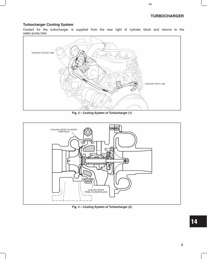
14
3
TURBOCHARGER
Turbocharger Cooling SystemCoolant for the turbocharger is supplied from the rear right of cylinder block and returns to thewater pump inlet.
Fig. 3 Cooling System of Turbocharger (1)
COOLANT INLET LINE
COOLANT OUTLET LINE
Fig. 4 Cooling System of Turbocharger (2)
COOLING WATER TO WATERPUMP INLET
COOLING WATERFROM CYLINDER BLOCK
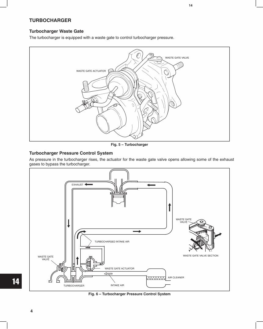
14
4
TURBOCHARGER
Turbocharger Waste GateThe turbocharger is equipped with a waste gate to control turbocharger pressure.
Fig. 5 Turbocharger
WASTE GATE ACTUATOR
WASTE GATE VALVE
Turbocharger Pressure Control SystemAs pressure in the turbocharger rises, the actuator for the waste gate valve opens allowing some of the exhaustgases to bypass the turbocharger.
Fig. 6 Turbocharger Pressure Control System
WASTE GATEVALVE
TURBOCHARGER
TURBOCHARGED INTAKE AIR
WASTE GATE ACTUATOR
INTAKE AIR
AIR CLEANER
WASTE GATEVALVE
WASTE GATE VALVE SECTION
EXHAUST

14
5
TURBOCHARGER
Crankcase Blow-by Recirculating SystemCrankcase blow-by is recirculated as shown in Fig. 7
Fig. 7 Crankcase Blow-by Recirculating System
FRESH AIR
BLOW-BY GASES
EXHAUST GASES
CRANKCASEBREATHER TUBE
T/C
A/C
EXIN
CHECKING WASTE GATE ACTUATOR1. Disconnect the waste gate actuator hose at the
actuator.2. Connect pressure/vacuum pump, Tool #19493.3. Apply pressure of 14.2 psi (0.9 bar) and ensure
that the rod and link operate.4. When pressure is released rod and link must
return to original position.NOTE: DO NOT apply pressure more than 21.3
psi (1.5 bar) to the waste gate actuator orthe diaphragm will be damaged.
5. If the actuator hose is damaged or cracked it mustbe replaced. Fig. 8 Checking Waste Gate Valve
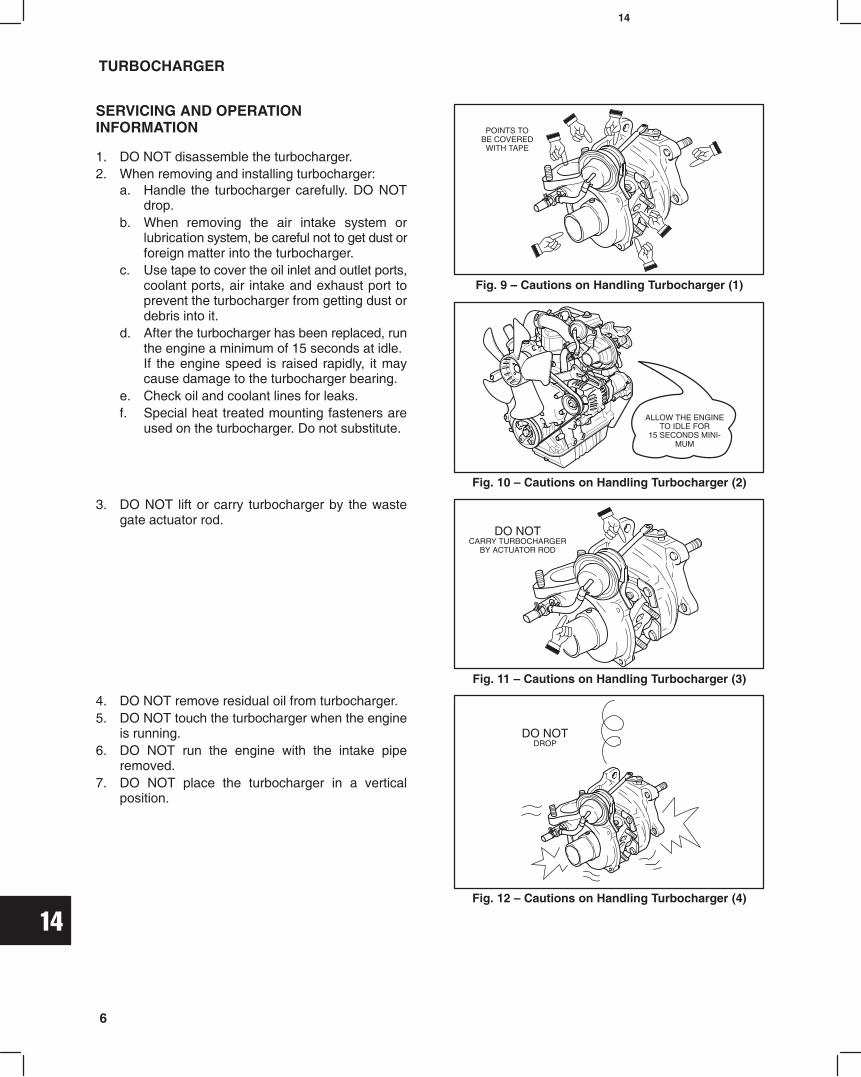
14
6
TURBOCHARGER
SERVICING AND OPERATIONINFORMATION
1. DO NOT disassemble the turbocharger.2. When removing and installing turbocharger:
a. Handle the turbocharger carefully. DO NOTdrop.
b. When removing the air intake system orlubrication system, be careful not to get dust orforeign matter into the turbocharger.
c. Use tape to cover the oil inlet and outlet ports,coolant ports, air intake and exhaust port toprevent the turbocharger from getting dust ordebris into it.
d. After the turbocharger has been replaced, runthe engine a minimum of 15 seconds at idle.If the engine speed is raised rapidly, it maycause damage to the turbocharger bearing.
e. Check oil and coolant lines for leaks.f. Special heat treated mounting fasteners are
used on the turbocharger. Do not substitute.
Fig. 9 Cautions on Handling Turbocharger (1)
POINTS TOBE COVERED
WITH TAPE
Fig. 10 Cautions on Handling Turbocharger (2)
ALLOW THE ENGINETO IDLE FOR
15 SECONDS MINI-MUM
3. DO NOT lift or carry turbocharger by the wastegate actuator rod.
Fig. 11 Cautions on Handling Turbocharger (3)
DO NOTCARRY TURBOCHARGER
BY ACTUATOR ROD
4. DO NOT remove residual oil from turbocharger.5. DO NOT touch the turbocharger when the engine
is running.6. DO NOT run the engine with the intake pipe
removed.7. DO NOT place the turbocharger in a vertical
position.
Fig. 12 Cautions on Handling Turbocharger (4)
DO NOTDROP

14
7
TURBOCHARGER
REMOVE TURBOCHARGER1. Remove the muffler or exhaust pipe from the
turbocharger.2. Lift tab on tie strap and remove tie strap. Then
remove crankcase breather tube at air intake tube.
Fig. 13 Remove Clamp
TIESTRAP
TAB
3. Disconnect the air intake tube at the turbocharger.4. Disconnect the air intake tube from the air intake
pipe.
AIR INTAKETUBE
Fig. 14 Disconnecting Air Intake Tube
5. Remove the two nuts, and remove the air intakepipe from turbocharger.
Fig. 15 Removing Air Intake Pipe
AIR INTAKE PIPE
6. Remove the coolant inlet hose from coolant inletline.
Fig. 16 Removing Coolant Hose
COOLANT HOSE

14
8
TURBOCHARGER
7. Remove coolant outlet hose.
Fig. 17 Disconnect Coolant Hose
OUTLET HOSE
8. Remove coolant inlet line bracket screw.
Fig. 18 Remove Clamp
BRACKET
9. Remove two nuts, then remove coolant lineassembly from turbocharger .
Fig. 19 Removing Coolant Line
10. Remove oil inlet line union screw at turbo-charger. Discard the washer.
Fig. 20 Removing Union Screw
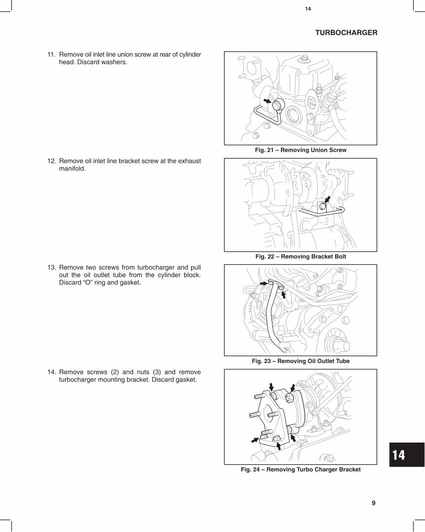
14
9
TURBOCHARGER
11. Remove oil inlet line union screw at rear of cylinderhead. Discard washers.
Fig. 21 Removing Union Screw
12. Remove oil inlet line bracket screw at the exhaustmanifold.
Fig. 22 Removing Bracket Bolt
13. Remove two screws from turbocharger and pullout the oil outlet tube from the cylinder block.Discard O ring and gasket.
Fig. 23 Removing Oil Outlet Tube
14. Remove screws (2) and nuts (3) and removeturbocharger mounting bracket. Discard gasket.
Fig. 24 Removing Turbo Charger Bracket
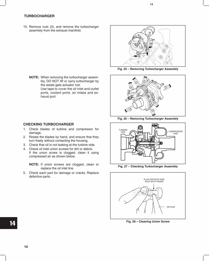
14
10
TURBOCHARGER
15. Remove nuts (3), and remove the turbochargerassembly from the exhaust manifold.
NOTE: When removing the turbocharger assem-bly, DO NOT lift or carry turbocharger bythe waste gate actuator rod.Use tape to cover the oil inlet and outletports, coolant ports, air intake and ex-haust port.
Fig. 25 Removing Turbocharger Assembly
Fig. 26 Removing Turbocharger Assembly
CHECKING TURBOCHARGER1. Check blades of turbine and compressor for
damage.2. Rotate the blades by hand, and ensure that they
turn freely without contacting the housing.3. Check that oil is not leaking at the turbine side.4. Check oil inlet union screws for dirt or debris.
If the union screw is clogged, clean it usingcompressed air as shown below.
NOTE: If union screws are clogged, clean orreplace the oil inlet line.
5. Check each part for damage or cracks. Replacedefective parts.
Fig. 27 Checking Turbocharger Assembly
Fig. 28 Cleaning Union Screw
TURBINESIDE COMPRESSOR
SIDE
PLUG OPPOSITE SIDEHOLE WITH FINGER
AIR GUN

14
11
TURBOCHARGER
INSTALL TURBOCHARGER
1. Install the turbocharger assembly with newgasket.a. Torque nuts (3) to 25 Nm (18.0 ft.-lb).
Fig. 29 Installing Turbocharger Assembly
2. Install the turbocharger bracket with new gasket.a. Temporarily tighten the nuts and bolts
until the flange surfaces of the turbocharger,exhaust manifold and turbocharger stay incontact each other.
b. First torque nuts to 34.0 Nm (25.0 ft.-lb)c. Then torque screws to 29.0 Nm (20.0 ft.-lb)
Fig. 30 Installing Turbocharger Bracket
3. Install oil outlet line.a. Insert the oil outlet tube into the cylinder block
with new O ring.b. Assemble to turbocharger with new gasket.c. Torque screws to 8.0 Nm (70.0 in-lb).
Fig. 31 Installing Oil Outlet Tube
OILOUTLET
LINE

14
12
TURBOCHARGER
4. Install oil inlet line.a. Temporarily install the union screw with
washers at the cylinder head.b. Temporarily install the union screw with
washer at the turbocharger.c. Temporarily install the inlet line bracket screw.d. Then torque union screws and bracket screw.
Union screws:Cylinder head side Turbocharger side 44.0 Nm 18.0 Nm (170 in-lb)(32.0 ft.-lb)
Bracket screw:19.0 Nm (170. in-lb)
Fig. 32 Installing Oil Inlet Line
Fig. 33 Installing Bracket Screw
5. Install Coolant Line at turbocharger with newgasket.a. Torque nuts to 8.0 Nm (70 in. lbs.).
Fig. 34 Installing Coolant Line
6. Install bracket screw.a. Torque screw to 19.0 Nm (170 in. lbs.).
TURBO WATERPIPE CLAMP
Fig. 35 Install Bracket Screw
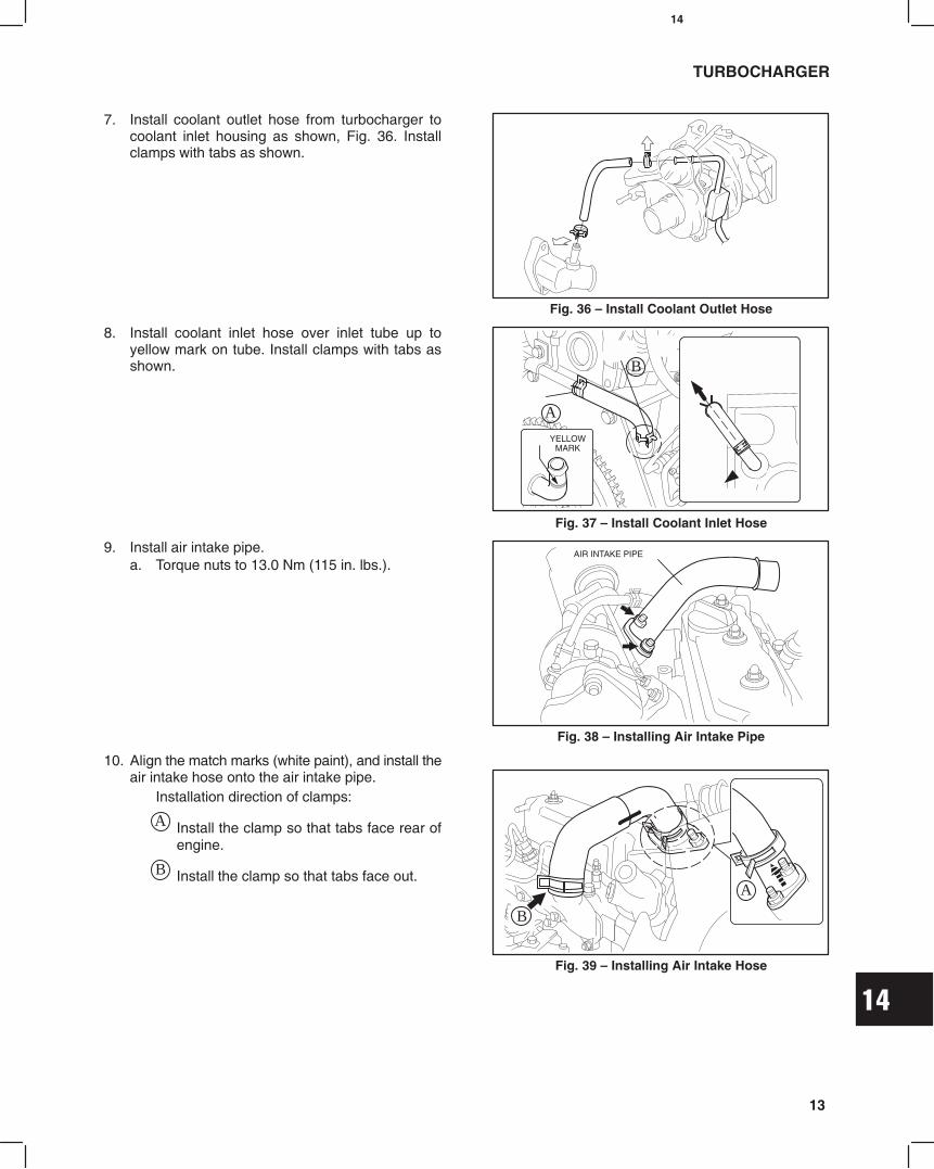
14
13
TURBOCHARGER
7. Install coolant outlet hose from turbocharger tocoolant inlet housing as shown, Fig. 36. Installclamps with tabs as shown.
Fig. 36 Install Coolant Outlet Hose
8. Install coolant inlet hose over inlet tube up toyellow mark on tube. Install clamps with tabs asshown.
Fig. 37 Install Coolant Inlet Hose
A
YELLOWMARK
B
9. Install air intake pipe.a. Torque nuts to 13.0 Nm (115 in. lbs.).
Fig. 38 Installing Air Intake Pipe
AIR INTAKE PIPE
10. Align the match marks (white paint), and install theair intake hose onto the air intake pipe.
Installation direction of clamps:
A Install the clamp so that tabs face rear ofengine.
B Install the clamp so that tabs face out.
Fig. 39 Installing Air Intake Hose
B
A
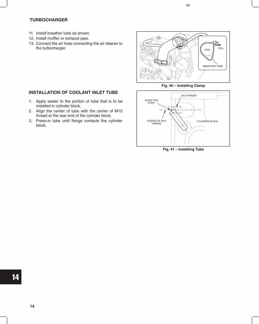
14
14
TURBOCHARGER
11. Install breather tube as shown.12. Install muffler or exhaust pipe.13. Connect the air hose connecting the air cleaner to
the turbocharger. PULL
Fig. 40 Installing Clamp
PIPE
BREATHER TUBE
INSTALLATION OF COOLANT INLET TUBE
1. Apply sealer to the portion of tube that is to beinstalled in cylinder block.
2. Align the center of tube with the center of M10thread at the rear end of the cylinder block.
3. Press-in tube until flange contacts the cylinderblock.
Fig. 41 Installing Tube
ALIGN THISPOINT
M10 THREAD
CYLINDER BLOCKCENTER OF M10THREAD
Related Documents