ACI 550.1R-01 became effective September 14, 2001. Copyright 2001, American Concrete Institute. All rights reserved including rights of reproduction and use in any form or by any means, including the making of copies by any photo process, or by electronic or mechanical device, printed, written, or oral, or recording for sound or visual reproduc- tion or for use in any knowledge or retrieval system or device, unless permission in writing is obtained from the copyright proprietors. ACI Committee Reports, Guides, Standard Practices, and Commentaries are intended for guidance in planning, designing, executing, and inspecting construction. This document is intended for the use of individuals who are competent to evaluate the significance and limitations of its content and recommendations and who will accept re- sponsibility for the application of the material it contains. The American Concrete Institute disclaims any and all re- sponsibility for the stated principles. The Institute shall not be liable for any loss or damage arising therefrom. Reference to this document shall not be made in con- tract documents. If items found in this document are de- sired by the Architect/Engineer to be a part of the contract documents, they shall be restated in mandatory language for incorporation by the Architect/Engineer. 550.1R-1 Emulating Cast-in-Place Detailing in Precast Concrete Structures ACI 550.1R-01 This report provides engineers with a practical guide for detailing precast concrete structures that should meet building code requirements in all seis- mic regions by emulating cast-in-place reinforced concrete design. This report also provides information that shows how emulative precast con- crete structures can address any or all of the provisions in accordance with ACI 318-99, including those of Chapter 21, if special attention is directed to detailing the joints and splices between precast components. Keywords: ductility; elastic design; emulation; flexural strength; joint; precast concrete; precast detailing; reinforcement. CONTENTS Chapter 1—Introduction, p. 550.1R-2 Chapter 2—General design procedures, p. 550.1R-2 2.1—Selecting a structural system 2.1.1—Shear walls 2.1.2—Box structures 2.1.3—Moment-resisting frames 2.1.4—Dual systems—frames and shear walls 2.2—Ductility and hinges 2.3—Design and analysis procedures 2.3.1—Moment frames 2.3.2—Shear walls Chapter 3—System components, p. 550.1R-6 Chapter 4—Connection of precast elements, p. 550.1R-7 4.1—Connections in wall systems 4.2—Connections in frame systems 4.3—Other connections—floor diaphragms 4.4—Special materials and devices Chapter 5—Guidelines for fabrication, transportation, erection, and inspection, p. 550.1R-14 Chapter 6—Examples of emulative precast concrete structures, p. 550.1R-15 Chapter 7—Summary and conclusions, p. 550.1R-15 Reported by Joint ACI-ASCE Committee 550 Robert Austin John T. Guthrie Cliff Ohlwiler * Donald Buettner Neil M. Hawkins Michael G. Oliva Clinton Calvert Mohammad Iqbal * Victor F. Pizano-Thomen Te-Lin “Terry” Chung Francis J. Jacques ‡ Sami H. Rizkalla Ned Cleland * L. S. Paul Johal Khaled A. Soudki Thomas J. D’Arcy Ken Luttrell John F. Stanton * Alvin C. Ericson *† Rafael Magana P. Jeffrey Wang Melvyn Galinat Lesile D. Martin C. E. Warnes * Michael Goff Vilas Mujumdar * Chair The committee acknowledges C. E. Warnes’ contribution for providing the initial information on emulation to the committee. * Members of ACI 550 subcommittee who prepared this report. † Subcommittee chair. ‡ Deceased.

Welcome message from author
This document is posted to help you gain knowledge. Please leave a comment to let me know what you think about it! Share it to your friends and learn new things together.
Transcript
Emulating Cast-in-Place Detailing in Precast Concrete Structures
ACI 550.1R-01
Reported by Joint ACI-ASCE Committee 550
Robert Austin John T. Guthrie Cliff Ohlwiler*
Donald Buettner Neil M. Hawkins Michael G. Oliva
Clinton Calvert Mohammad Iqbal* Victor F. Pizano-Thomen
Te-Lin “Terry” Chung Francis J. Jacques‡ Sami H. Rizkalla
Ned Cleland* L. S. Paul Johal Khaled A. Soudki
Thomas J. D’Arcy Ken Luttrell John F. Stanton*
Alvin C. Ericson*† Rafael Magana P. Jeffrey Wang
Melvyn Galinat Lesile D. Martin C. E. Warnes*
Michael Goff
Vilas Mujumdar*
Chair
The committee acknowledges C. E. Warnes’ contribution for providing the initial information on emulation to the committee.*Members of ACI 550 subcommittee who prepared this report.†Subcommittee chair.‡Deceased.
ACI Committee Reports, Guides, Standard Practices,and Commentaries are intended for guidance in planning,designing, executing, and inspecting construction. Thisdocument is intended for the use of individuals who arecompetent to evaluate the significance and limitations ofits content and recommendations and who will accept re-sponsibility for the application of the material it contains.The American Concrete Institute disclaims any and all re-sponsibility for the stated principles. The Institute shallnot be liable for any loss or damage arising therefrom.
Reference to this document shall not be made in con-tract documents. If items found in this document are de-sired by the Architect/Engineer to be a part of the contractdocuments, they shall be restated in mandatory languagefor incorporation by the Architect/Engineer.
This report provides engineers with a practical guide for detailing precastconcrete structures that should meet building code requirements in all seis-mic regions by emulating cast-in-place reinforced concrete design. Thisreport also provides information that shows how emulative precast con-crete structures can address any or all of the provisions in accordance withACI 318-99, including those of Chapter 21, if special attention is directedto detailing the joints and splices between precast components.
Keywords: ductility; elastic design; emulation; flexural strength; joint;precast concrete; precast detailing; reinforcement.
CONTENTSChapter 1—Introduction, p. 550.1R-2
Chapter 2—General design procedures, p. 550.1R-22.1—Selecting a structural system
550.1
ACI 550.1R-01 became effective September 14, 2001.Copyright 2001, American Concrete Institute.All rights reserved including rights of reproduction and use in any form or by any
means, including the making of copies by any photo process, or by electronic ormechanical device, printed, written, or oral, or recording for sound or visual reproduc-tion or for use in any knowledge or retrieval system or device, unless permission inwriting is obtained from the copyright proprietors.
2.1.1—Shear walls2.1.2—Box structures2.1.3—Moment-resisting frames2.1.4—Dual systems—frames and shear walls
2.2—Ductility and hinges2.3—Design and analysis procedures
2.3.1—Moment frames2.3.2—Shear walls
Chapter 3—System components, p. 550.1R-6
Chapter 4—Connection of precast elements,p. 550.1R-7
4.1—Connections in wall systems4.2—Connections in frame systems4.3—Other connections—floor diaphragms4.4—Special materials and devices
Chapter 5—Guidelines for fabrication, transportation, erection, and inspection, p. 550.1R-14
Chapter 6—Examples of emulative precast concrete structures, p. 550.1R-15
Chapter 7—Summary and conclusions, p. 550.1R-15
R-1

550.1R-2 ACI COMMITTEE REPORT
Chapter 8—References, p. 550.1R-158.1—Referenced standards and reports8.2—Cited references8.3—Other references
CHAPTER 1—INTRODUCTIONEmulative detailing is defined as designing connection
systems in a precast concrete structure so that its structuralperformance is equivalent to that of a conventionally designed,cast-in-place, monolithic concrete structure (Ericson andWarnes 1990).
Emulative detailing is different than jointed design whereprecast elements are separated from each other but areconnected with special jointing details like welded orbolted plates. As commonly applied, the term “emulation”refers to the design of the vertical or horizontal elementsof the lateral-force-resisting system of a building. Emulativedetailing of precast concrete structures is applicable to anystructural system where monolithic reinforced concretewould also be appropriate, regardless of seismic region(Precast/Prestressed Concrete Institute 1999).
Design practice in some countries with a high seismic risk,such as New Zealand and Japan, follow design codes thataddress precast concrete designed by emulation of cast-in-place concrete design. Performance of joints and relateddetails of emulative precast concrete structural conceptshave been extensively tested in Japan. Because emulativeprecast concrete structures have been constructed there forover three decades, emulative methods for seismic designare widely accepted. Until recently, this practice has notbeen formally followed in the U.S.
Typical details showing proportional dimensions, as wellas reinforcing steel, are schematic only and are provided solelyto demonstrate the interactivity of the jointing essentials. Allconnection details will be subject to structural analysis andcompliance with contemporary code requirements. At thetime of this writing, splicing reinforcing bars by welding orlapping was not permitted by code whenever the bars weresubjected to stresses beyond the actual yield points of thereinforcing steel being used. According to certain tests ofmechanical splices reported by the California Department ofTransportation (Noureddine, Richards, and Grottkau 1996),concern was expressed about staggering of mechanical splicesof reinforcing bars. Staggering is not required by current anddeveloping codes.
Only reinforcing bar details essential to make the illustra-tion more understandable are shown to avoid congestion andprovide clarity. Other reinforcing steel that would typicallybe incorporated into a conventional design is intentionallynot shown. The specification and delineation of reinforcingbars or strand sizes and locations, layers, types, and numbersis the responsibility of the designer.
CHAPTER 2—GENERAL DESIGN PROCEDURESA large body of technical information is available for the
design of cast-in-place reinforced concrete structures, andextensive research and development is on-going for alltypes of cast-in-place concrete technology. Numerous text-
books have been written about the behavior and design ofcast-in-place reinforced concrete. Design procedures and ex-amples for cast-in-place reinforced concrete are available(Cole/Yee/Schubert and Associates 1993). Building codesare regularly revised to reflect new research and technologydevelopments, and the results are incorporated into teachingand working practice (Uniform Building Code; ACI 318).This knowledge for designing reinforced cast-in-place con-crete structures is readily applicable to the design of emula-tive precast concrete.
The analysis and design of cast-in-place reinforced con-crete structures is based on the premise that the entire systembehaves monolithically as a unit. A cast-in-place concretestructure is actually built section by section with joints be-tween the concrete placements because of limitations in con-crete placing, construction procedures, or both. Due to thecontinuity of the reinforcement and specific requirements forconstruction joints, the structure performs as a unit. Theprincipal element of the emulative detailing of precast con-crete is to detail a precast structure that will exhibit structuralbehavior similar to that of a cast-in-place structure.
Construction joints, whether in prefabricated or cast-in-place concrete structures, should be located and detailed toensure transmission of induced forces and loads in both theconcrete and reinforcing steel. For precast concrete, emula-tive construction joints will likely occur at the same loca-tions as dry joints in the structural elements. Joints willusually be located at the ends of beams and columns, at boththe ends and sides of floor elements, and at the joints be-tween wall elements.
The essential differences between cast-in-place reinforcedconcrete and emulative, reinforced, precast concrete relate tofield connections and assembly of the prefabricated elements.Prefabricated elements have additional design requirementfor stripping, transportation, and erection loads imposedon them, but the structural analysis and element design isessentially the same for both types of construction.
Using emulative methods for connecting precast concreteelements, the detailing process will follow three general steps:
1. The desired structural system for resisting gravity andlateral loads is selected. A separate gravity-load-resistingframe can be combined with lateral-load-resisting shearwalls, or both functions can be accomplished with moment-resisting frames. System selection is often controlled by theheight of the building and the span of the components as wellas architectural requirements.
2. Design and detail the structure to meet the requirementsof the applicable building code as if it is to be constructed ofmonolithic cast-in-place reinforced concrete, keeping inmind that the structure will be divided into structural elementsof sizes and shapes that:
• Are suitable for plant fabrication;• Are capable of being transported; and• Can be erected by cranes available to the contractor.
3. Organize the structure on paper into typical precast ele-ments of appropriate sizes and shapes to meet the foregoingcriteria. Then design and detail the appropriate connectionsto satisfy the requirements of the applicable building code to
EMULATING CAST-IN-PLACE DETAILING IN PRECAST CONCRETE STRUCTURES 550.1R-3
allow the precast elements to be reconnected in a way thatemulates a monolithic system.
The manufacture and construction of precast structureswill normally follow five steps:
1. Manufacture the precast structural elements with code-compliant mechanisms for splicing the structural reinforcingbars to provide continuity of the reinforcement throughoutthe structure;
2. Transport the prefabricated elements to the project siteif they are cast offsite;
3. Erect and temporarily secure each individual precastelement;
4. Connect the reinforcing bars between the precast con-crete elements by completing the splices;
5. Connect the precast concrete elements with grout orconcrete closures; and
6. Reshore horizontal elements as required.
2.1—Selecting a structural systemSelecting an appropriate structural system, such as shear
walls, box structures, moment-resisting frames, and dualsystems for both lateral and gravity loads, can be the mostimportant step in achieving an economical, structurallysound design. Essentially, four types of structural elementsaddressed in model codes are used in combination to formcomplete building systems. Horizontal elements includebeams and slabs. Vertical structural elements include wallsand columns or combinations of both horizontal and verticalelements, such as cruciform elements. These elements can becombined in various configurations to form commonlyrecognized lateral-load-resisting systems, such as shearwalls and moment-resisting frames. Emulative detailingprinciples apply to all of them.
With precast concrete, the designer has the option to selectonly those frames or walls necessary to resist loads under thecode requirements. For seismic conditions, the elements of thegravity load frame need only meet the requirements of ACI318-99, Section 21.9 (frame members not proportioned to re-sist forces induced by earthquake motions) and the require-ment that each precast member be connected to adjacentmembers. This requirement can impose additional engineer-ing considerations even when using emulation detailing.
2.1.1 Shear walls—Shear walls resist forces in the struc-ture parallel to the plane of the wall. Because of the relativelylarge depth of the wall members in-plane, significant lateralstiffness is provided. Structures that have shear walls as theprincipal lateral-load-resisting elements usually perform betterunder earthquake loading than moment frame structures. Therewere failures in various degrees in six structures of Northridge.Three parking garage structures used precast elements. Theother three were in cast-in-place concrete. Shear walls wereintact in both systems (Iverson and Hawkins 1994).
There were failures in various degrees in six concretestructures at Northridge. Three of the parking structures usedprecast elements.
Three were cast-in-place concrete. Two parking garagesusing PCI-recommended jointing details for double tee floor
systems suffered floor diaphragm failures. Shear walls wereintact on both.
The International Building Code, IBC 2000, based on theNational Earthquake Hazards Reduction Program (NEHRP)(Building Seismic Safety Council 1997) recommended pro-visions, recognizes two classifications of shear walls. “Ordi-nary shear walls” are walls designed in accordance with ACI318 Chapters 1 through 18. This includes Chapter 16 on pre-cast concrete with provisions for structural integrity. Ordi-nary shear walls are permitted in buildings in seismicperformance categories: A, B, and C. These requirements donot include the seismic detailing provisions of Chapter 21.Systems braced with ordinary shear walls are assigned a re-sponse modification factor, R, of 4.5 for load-bearing wallsystems, and 5 for shear walls bracing a vertical frame.
The second classification of shear walls in the IBC 2000 is“Special Shear Walls.” These walls meet the requirementsfor ductile detailing included in ACI 318-99, Section 21.6,“Special reinforced concrete structural walls and couplingbeams.” Systems braced with special shear walls are assigneda response modification factor of 5.5 for load-bearing wallsystems, and 6 for shear walls bracing a vertical frame.Special shear walls are used in buildings in seismic performancecategories: D, E, and F. Although not required for regions oflower seismic risk, engineers can design special shear wallsfor these conditions for their increased integrity, strength,and ductility, and for the reduction of base shears afforded bythe higher R factors.
For ordinary precast shear walls, emulation does not pro-vide specific benefit. The level of strength and ductility re-flected by the R factors only requires the standard details usedwith precast and tilt-up construction. For special shear walls,however, only those walls that meet the ACI 318 Chapter 21requirements are recognized. Precast walls, then, need to em-ulate the performance and detailing of monolithic cast-in-place walls using the rules that were developed for cast-in-place construction. At this time, the only alternative to emu-lation for special shear walls is the general provision of ACI318-99 Section 21.2.1.5, which allows alternative systems ifthe proposed system is demonstrated by experimental evi-dence and analysis to have strength and toughness equivalentto cast-in-place reinforced concrete. For moment frames, theengineer can refer to ACI ITG/T1.1-99, “Acceptance Criteriafor Moment Frames Based on Structural Testing.” However,this is not considered emulation, but rather a special proce-dure to allow newly-developed jointed frame systems.
Although not prescribed explicitly in the codes, provisionsdo allow for the consideration of soil-structure interaction.NEHRP (Building Seismic Safety Council 1997) includesrequirements that permit the consideration of soil-structureinteraction in design. These considerations reflect the increasedflexibility and damping due to interaction between thefoundation and soil continuum. Such interaction may decreasethe design values of base shear, lateral forces, and overturningmoments, but they may increase the values of the lateral dis-placements and the secondary forces associated with P-deltaeffects. When using stiff wall elements, however, the in-creased displacements may have minimal effect on overall

550.1R-4 ACI COMMITTEE REPORT
stability. Although the primary mode of inelastic behavior isat the soil/foundation interface, the prescriptive provisionsfor detailing the structure, which include increased ductilityin regions of high seismic risk, are not relaxed.
The desired primary ductile behavior of shear walls emu-lating cast-in-place detailing is flexural yielding at the wallbase and wall joints (Fig. 1). Providing ductility is the intentof the detailing requirements imposed by ACI 318-99, Sec-tion 21.6. These include:• Minimum web reinforcement ratio of 0.0025, unless
the design shear force does not exceed (whereAcv is the gross area of concrete section bounded by web
Acv f ′c
Fig. 1—Dual building with rotation of the shear wall ateach floor.
Fig. 2—Dual building, ductile yielding of partially debondedbars between foundation and shear wall boundary elements.
Fig. 3—Precast shear tower using mechanical splices andcast-in-place closure connections between elements.
thickness and length of section in the direction of shearforce considered, in.2; and fc
′ is the specified compres-sive strength of concrete, psi). Even if this low shearlimit is met, the minimum web steel still has to meet theminimum steel requirements of Chapter 14 for walls;
• Maximum reinforcement spacing of 18 in. (457 mm);• At least two curtains of reinforcement need to be used
in the wall and in the wall-to-foundation interface if theshear force exceeds ; and
• Continuous reinforcement in walls needs to beanchored or spliced as tension steel.
Because a small rotation in a wall will create a large demandfor bar elongation, the ductility at the base is important. Duc-tility can be increased significantly by debonding bars into andout of the foundation so that they can deform inelastically overa longer length (Soudki, Rizkalla, and LeBlanc 1995), thus re-sulting in greater nonlinear elongation and rotational ductility(Fig. 2). Reinforcing steel specified for special walls should beductile and have controlled strength properties. ACI 318-99,Section 21.2.5, requires that reinforcement resisting earth-quake forces meet ASTM A 706 with some exceptions.
2.1.2 Box structures—Box structures are a special type ofbuilding and may fall under the category of walls. Familiar ex-amples of box or cellular structures, shown in Fig. 3 and 4, in-clude stairwells, elevator cores, and panel-type multistoryresidential buildings. The overlapping corners shown in Fig. 4provide a strong shear component when completed. In partic-ular cases, when the boxes include integral floors, ceilings, orboth, they have been called cells. Even though a large numberand variety of buildings falling under this category have beenconstructed in North America, it has been primarily the Archi-tectural Institute of Japan (AIJ) that has formalized the classi-fication of box structures as a structural system forearthquake-resistant buildings (Suenga 1974).
A box is a three-dimensional cell. Monolithic cells can be em-ulated by constructing with three-dimensional modules or byassembling with separately manufactured floor and wall panels.
2Acv f ′c
Fig. 4—Use of mechanical connections and interlockingprecast wall elements to create a monolithic shear tower.Note: Erection sequencing must be coordinated.
EMULATING CAST-IN-PLACE DETAILING IN PRECAST CONCRETE STRUCTURES 550.1R-5
2.1.3 Moment-resisting frames—Moment-resisting frames(both steel and reinforced concrete) are used for buildings overa wide range of heights.
There is no technical reason why high-rise, reinforcedconcrete moment-resisting frames cannot be designed,even to resist large earthquakes, with the intention of havingthe structure remain elastic. When structures are required toremain elastic, however, elastic design procedures requirelarger structural members to resist stresses resulting fromearthquake loads. This leads to increased material costs aswell as higher lateral forces on nonstructural elements, andprobable loss of some floor and window opening space dueto bulkier columns. Under elastic design provisions, beamsmay require greater depth, resulting in increased storyheights and, consequently, resulting in taller buildings. Inregions where relatively minor earthquake loads are expected,elastic design methods can be appropriate when it may not beeconomical to detail for ductility. The NEHRP-based codeprovisions permit the use of ordinary moment frames forseismic performance categories A and B.
In June 1978, NEHRP was created. The NEHRP Recom-mended Provisions for the Development of Seismic Regula-tions for New Buildings was first published in 1985 andsubsequently updated on a 3-year cycle. These provisions haveincluded not only recommendations for the evaluations ofloads and general building details, but also material-specificparameters and detailing provisions that are consistent withthose general recommendations.
The 1994 edition of the Recommended Provisions wasused in making major changes to the Internal Conference ofBuilding Officials (ICBO) Uniform Building Code (UBC)1997. The 1997 edition became the basis for the newlymerged International Code Council (ICC) InternationalBuilding Code 2000 model code seismic provisions.
Ductility is an important factor in the design of framebuildings for more severe earthquake regions, such as thoseconstructed in UBC Zones 3 and 4. Buildings in NEHRPseismic performance category C require intermediate momentframes. Buildings of seismic performance categories D, E, andF require special moment-resistant frames (SMRF).
Concrete frames can be readily designed to perform in aductile manner. Full-scale tests of reinforced concrete beam-column connections have shown that such connections areductile and can perform effectively under earthquake load-ing. Plastic hinging of beam-end connections is highly depen-dent upon the type and amount of reinforcement used in theintended ductile hinge region, usually at or near beam ends.
Chapter 21 of ACI 318-99 provides prescriptive require-ments for special moment frames intended to ensure strongcolumn-weak beam behavior.
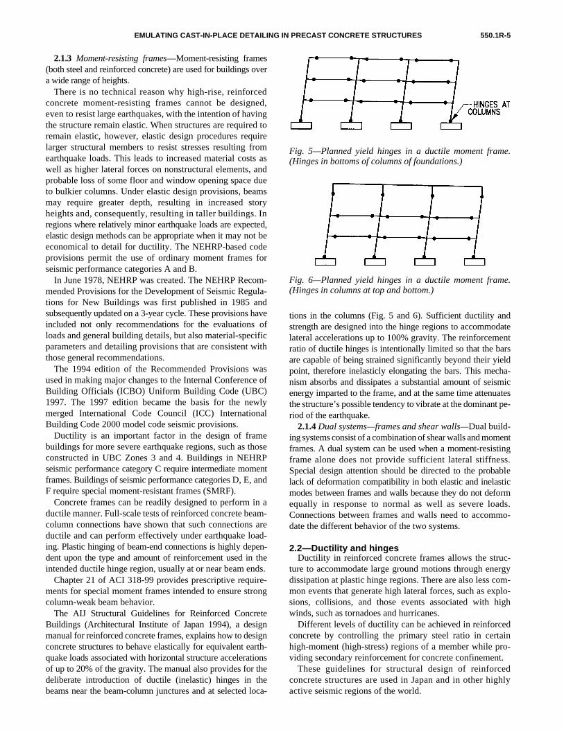
The AIJ Structural Guidelines for Reinforced ConcreteBuildings (Architectural Institute of Japan 1994), a designmanual for reinforced concrete frames, explains how to designconcrete structures to behave elastically for equivalent earth-quake loads associated with horizontal structure accelerationsof up to 20% of the gravity. The manual also provides for thedeliberate introduction of ductile (inelastic) hinges in thebeams near the beam-column junctures and at selected loca-
tions in the columns (Fig. 5 and 6). Sufficient ductility andstrength are designed into the hinge regions to accommodatelateral accelerations up to 100% gravity. The reinforcementratio of ductile hinges is intentionally limited so that the barsare capable of being strained significantly beyond their yieldpoint, therefore inelasticly elongating the bars. This mecha-nism absorbs and dissipates a substantial amount of seismicenergy imparted to the frame, and at the same time attenuatesthe structure’s possible tendency to vibrate at the dominant pe-riod of the earthquake.
2.1.4 Dual systems—frames and shear walls—Dual build-ing systems consist of a combination of shear walls and momentframes. A dual system can be used when a moment-resistingframe alone does not provide sufficient lateral stiffness.Special design attention should be directed to the probablelack of deformation compatibility in both elastic and inelasticmodes between frames and walls because they do not deformequally in response to normal as well as severe loads.Connections between frames and walls need to accommo-date the different behavior of the two systems.
2.2—Ductility and hingesDuctility in reinforced concrete frames allows the struc-
ture to accommodate large ground motions through energydissipation at plastic hinge regions. There are also less com-mon events that generate high lateral forces, such as explo-sions, collisions, and those events associated with highwinds, such as tornadoes and hurricanes.
Different levels of ductility can be achieved in reinforcedconcrete by controlling the primary steel ratio in certainhigh-moment (high-stress) regions of a member while pro-viding secondary reinforcement for concrete confinement.
These guidelines for structural design of reinforcedconcrete structures are used in Japan and in other highlyactive seismic regions of the world.
Fig. 5—Planned yield hinges in a ductile moment frame.(Hinges in bottoms of columns of foundations.)
Fig. 6—Planned yield hinges in a ductile moment frame.(Hinges in columns at top and bottom.)

550.1R-6 ACI COMMITTEE REPORT
The AIJ standard requires a structure to have a minimumlateral-load-resisting carrying capacity to limit the responsedeformation during an earthquake. It also requires the formationof a ductile yield mechanism to dissipate energy from the earth-quake; that is, a structural designer should plan a desirableyield mechanism for a structure expected to undergo a designearthquake and then generate such a yield mechanism in thebeams during a strong earthquake. Yield mechanisms inmoment frames should also be provided between founda-tions and the base of columns and, under circumstancesrelating to the amount of acceptable damage to the roofsystem, at the tops of columns.
Under the AIJ approach, the designer first plans a desirableyield mechanism to give both the required strength to thestructure and sufficient ductility to the planned yield hinges(yield-mechanism-design). Next, the designer providesnonyielding regions and members with sufficient elasticstrength to encourage the formation of the planned yield mech-anism in the intended location of the structure (yield-mecha-nism-assuring-design). Another feature is a new approach inshear design of members based on a plasticity theorem, inwhich shear is designed to be resisted by concrete arch andtruss mechanisms. This shear design method can be used forbeams, columns, and structural walls.
The earthquake resistance of this design approach relies onthe energy-dissipation capacity at the planned yield hinges,usually located in beams adjacent to the column faces and incolumns and walls at the foundation. Therefore, applyingthis method is limited to those parts of structures that can de-velop clearly-defined yield mechanisms.
Because ductility in ordinary (not prestressed) reinforcedconcrete is mostly a function of the mild steel bars used for re-inforcing, a yield mechanism is established in the reinforce-ment at an intended hinge location to be high enough to exceedthe yield point of the steel. This is accomplished by deliberatelylimiting the cross-sectional area As of the steel reinforcement inthe intended hinge region, forcing inelastic deformation.
When the natural vibration period of a building, or a har-monic of it, is close to the frequency of seismic waves, thevibration amplitude of the building is reinforced, somethinglike continuously striking a tuning fork. This causes thebuilding to sway back and forth at an ever-increasing exten-sion during the length of time the earthquake continues, theeffect being to magnify the intensity of forces. When yieldhinges are incorporated into the structure, the yielding of thereinforcement in the hinges dissipates a large amount ofenergy. This attenuates the natural vibration period of thebuilding so that it cannot resonate in sympathy with thefrequency of the earthquake.
2.3—Design and analysis procedures In general, a building will be classified as a shear-wall
structure, moment-frame, or dual system. Preliminary designloads, including seismic-equivalent static-lateral loads, arecalculated according to codes and assume the structure to bemonolithic cast-in-place concrete. Once the structural elementsare preliminarily proportioned, more accurate calculationsusing Rayleigh’s method or a finite-element analysis will
frequently result in smaller design loads than those obtainedfrom an initial application of the “equivalent static load”method. The more-accurate loads are then applied to thestructural model and the internal design forces are calculated.
2.3.1 Moment frames—Analysis of an emulative precastconcrete structure follows the same structural analysis pro-cedure as that used for analysis of a cast-in-place reinforcedconcrete structure.
The required strength of the various components of a lateral-force-resisting system will be determined by the analysis of alinearelastic model of the system. For frames, elastic analysisis used to determine the flexural strength required at the endsof the beams as they frame into the column. To ensure ductilebehavior, the steel reinforcement ratio within a ductilehinge region is limited by code to a maximum of 0.025.The positive moment capacity of strength in the beam at thecolumn face has to be at least 50% of the negative momentcapacity to resist reversals due to cyclic loading. The balanceof the design of the special moment frame, then, is based onmaking this area the weak link in the frame system.
Columns above and below a joint should have a total flexuralcapacity Mc that is 20% greater than the sum of the flexural ca-pacity Mg of the beams framing into the joint as provided byACI 318-99, Eq. (21-1).
ΣMc ≥ (6/5)ΣMg
The requirements for transverse reinforcement in bothbeams and columns are intended to ensure that the shearstrength does not limit the frame capacity and that the areasof yielding are well confined for stable behavior beyondflexural yielding.
2.3.2 Shear walls—For walls, simplified analysis methodsthat rely on the relative shear and flexural stiffness of the wallsare available (Precast/Prestressted Concrete Institute 1997).Analysis should consider the effects of shear deformations forwalls with aspect ratios lower than 3-to-1. The effects of theeccentricity of the center of mass differing from the center ofstiffness of the wall system should be considered along withthe code requirement to include 5% eccentricity for accidentaltorsion. For most precast systems, the stiffness contributionmade by connecting the floor to the walls is usually largeenough to create moment reversals or fixity in the wall at thefloors. Precast walls, then—even those that emulate monolith-ic construction—should be designed as cantilevered from thefoundation.
CHAPTER 3—SYSTEM COMPONENTSPrecast concrete elements are usually produced in a man-
ufacturing plant and then transported to their assigned posi-tions in the building. When detailing the monolithicallydesigned structural elements into discrete precast components,the designer should consider transportation and erection limi-tations. These limitations include weight (pavement andbridge capacities), height (bridge, tunnel, and underpass clear-ance), length (maneuverability and state laws), width (permits,escorts, and state laws), and available crane capacities.
EMULATING CAST-IN-PLACE DETAILING IN PRECAST CONCRETE STRUCTURES 550.1R-7
For shear-wall structures, highway bridge-clearance gener-ally restricts panel dimensions. Clearance limitations usuallyrestrict box module heights to approximately one building sto-ry. Floor planks and panels are usually narrower than wallpanels and a number of pieces can be shipped on each truck.
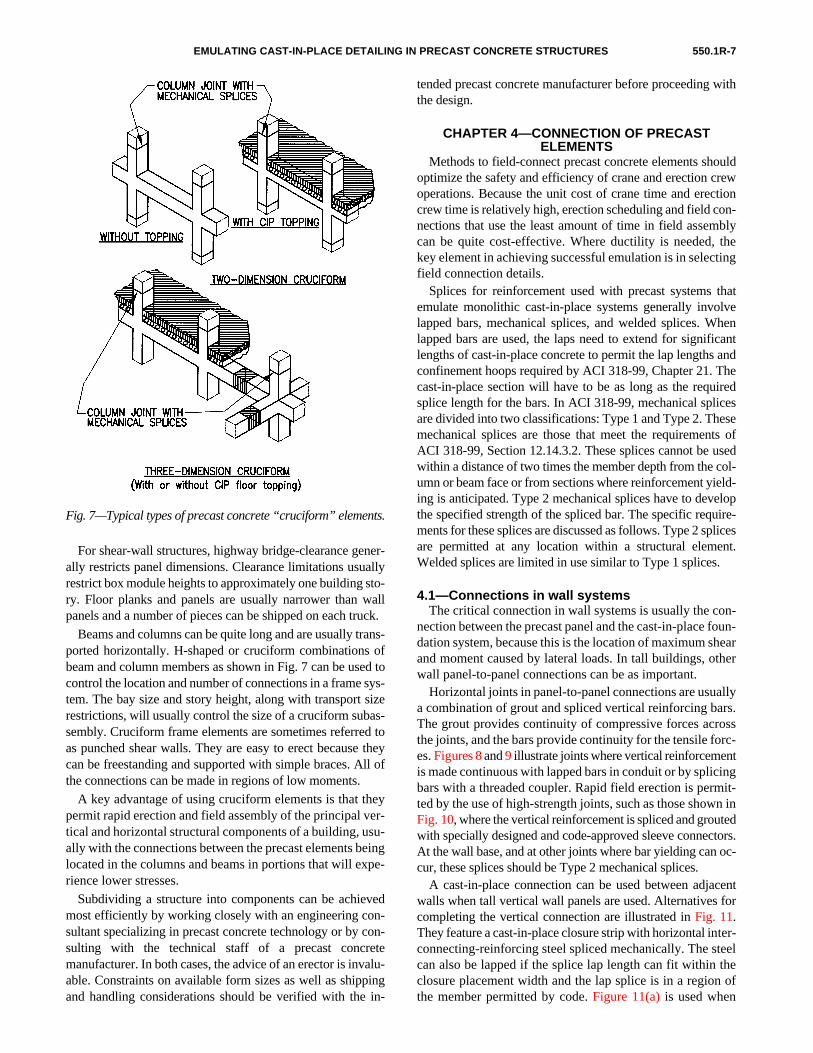
Beams and columns can be quite long and are usually trans-ported horizontally. H-shaped or cruciform combinations ofbeam and column members as shown in Fig. 7 can be used tocontrol the location and number of connections in a frame sys-tem. The bay size and story height, along with transport sizerestrictions, will usually control the size of a cruciform subas-sembly. Cruciform frame elements are sometimes referred toas punched shear walls. They are easy to erect because theycan be freestanding and supported with simple braces. All ofthe connections can be made in regions of low moments.
A key advantage of using cruciform elements is that theypermit rapid erection and field assembly of the principal ver-tical and horizontal structural components of a building, usu-ally with the connections between the precast elements beinglocated in the columns and beams in portions that will expe-rience lower stresses.
Subdividing a structure into components can be achievedmost efficiently by working closely with an engineering con-sultant specializing in precast concrete technology or by con-sulting with the technical staff of a precast concretemanufacturer. In both cases, the advice of an erector is invalu-able. Constraints on available form sizes as well as shippingand handling considerations should be verified with the in-
Fig. 7—Typical types of precast concrete “cruciform” elements.
tended precast concrete manufacturer before proceeding withthe design.
CHAPTER 4—CONNECTION OF PRECAST ELEMENTS
Methods to field-connect precast concrete elements shouldoptimize the safety and efficiency of crane and erection crewoperations. Because the unit cost of crane time and erectioncrew time is relatively high, erection scheduling and field con-nections that use the least amount of time in field assemblycan be quite cost-effective. Where ductility is needed, thekey element in achieving successful emulation is in selectingfield connection details.
Splices for reinforcement used with precast systems thatemulate monolithic cast-in-place systems generally involvelapped bars, mechanical splices, and welded splices. Whenlapped bars are used, the laps need to extend for significantlengths of cast-in-place concrete to permit the lap lengths andconfinement hoops required by ACI 318-99, Chapter 21. Thecast-in-place section will have to be as long as the requiredsplice length for the bars. In ACI 318-99, mechanical splicesare divided into two classifications: Type 1 and Type 2. Thesemechanical splices are those that meet the requirements ofACI 318-99, Section 12.14.3.2. These splices cannot be usedwithin a distance of two times the member depth from the col-umn or beam face or from sections where reinforcement yield-ing is anticipated. Type 2 mechanical splices have to developthe specified strength of the spliced bar. The specific require-ments for these splices are discussed as follows. Type 2 splicesare permitted at any location within a structural element.Welded splices are limited in use similar to Type 1 splices.
4.1—Connections in wall systemsThe critical connection in wall systems is usually the con-
nection between the precast panel and the cast-in-place foun-dation system, because this is the location of maximum shearand moment caused by lateral loads. In tall buildings, otherwall panel-to-panel connections can be as important.
Horizontal joints in panel-to-panel connections are usuallya combination of grout and spliced vertical reinforcing bars.The grout provides continuity of compressive forces acrossthe joints, and the bars provide continuity for the tensile forc-es. Figures 8 and 9 illustrate joints where vertical reinforcement
is made continuous with lapped bars in conduit or by splicingbars with a threaded coupler. Rapid field erection is permit-ted by the use of high-strength joints, such as those shown inFig. 10, where the vertical reinforcement is spliced and grouted with specially designed and code-approved sleeve connectors.At the wall base, and at other joints where bar yielding can oc-cur, these splices should be Type 2 mechanical splices.A cast-in-place connection can be used between adjacentwalls when tall vertical wall panels are used. Alternatives forcompleting the vertical connection are illustrated in Fig. 11.
They feature a cast-in-place closure strip with horizontal inter-connecting-reinforcing steel spliced mechanically. The steelcan also be lapped if the splice lap length can fit within theclosure placement width and the lap splice is in a region ofthe member permitted by code. Figure 11(a) is used when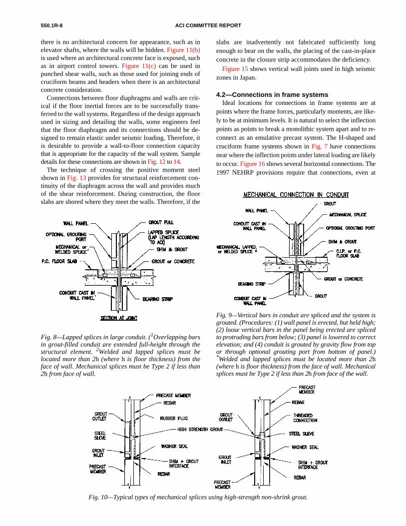
550.1R-8 ACI COMMITTEE REPORT
Fig. 8—Lapped splices in large conduit. (1Overlapping barsin grout-filled conduit are extended full-height through thestructural element. 2Welded and lapped splices must belocated more than 2h (where h is floor thickness) from theface of wall. Mechanical splices must be Type 2 if less than2h from face of wall.
Fig. 9—Vertical bars in conduit are spliced and the system isgrouted. (Procedures: (1) wall panel is erected, but held high;(2) loose vertical bars in the panel being erected are splicedto protruding bars from below; (3) panel is lowered to correctelevation; and (4) conduit is grouted by gravity flow from topor through optional grouting port from bottom of panel.)*Welded and lapped splices must be located more than 2h(where h is floor thickness) from the face of wall. Mechanicalsplices must be Type 2 if less than 2h from face of the wall.
Fig. 10—Typical types of mechanical splices using high-strength non-shrink grout.
there is no architectural concern for appearance, such as inelevator shafts, where the walls will be hidden. Figure 11(b)is used where an architectural concrete face is exposed, suchas in airport control towers. Figure 11(c) can be used inpunched shear walls, such as those used for joining ends ofcruciform beams and headers when there is an architecturalconcrete consideration.
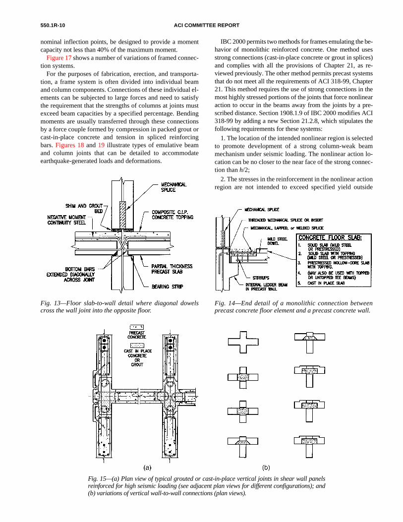
Connections between floor diaphragms and walls are crit-ical if the floor inertial forces are to be successfully trans-ferred to the wall systems. Regardless of the design approachused in sizing and detailing the walls, some engineers feelthat the floor diaphragm and its connections should be de-signed to remain elastic under seismic loading. Therefore, itis desirable to provide a wall-to-floor connection capacitythat is appropriate for the capacity of the wall system. Sampledetails for these connections are shown in Fig. 12 to 14.
The technique of crossing the positive moment steelshown in Fig. 13 provides for structural reinforcement con-tinuity of the diaphragm across the wall and provides muchof the shear reinforcement. During construction, the floorslabs are shored where they meet the walls. Therefore, if the
slabs are inadvertently not fabricated sufficiently longenough to bear on the walls, the placing of the cast-in-placeconcrete in the closure strip accommodates the deficiency.
Figure 15 shows vertical wall joints used in high seismic
zones in Japan.4.2—Connections in frame systemsIdeal locations for connections in frame systems are at
points where the frame forces, particularly moments, are like-ly to be at minimum levels. It is natural to select the inflectionpoints as points to break a monolithic system apart and to re-connect as an emulative precast system. The H-shaped andcruciform frame systems shown in Fig. 7 have connectionsnear where the inflection points under lateral loading are likelyto occur. Figure 16 shows several horizontal connections. The1997 NEHRP provisions require that connections, even at

EMULATING CAST-IN-PLACE DETAILING IN PRECAST CONCRETE STRUCTURES 550.1R-9
Fig. 11—Variations of splices and cast-in-place closure placements to create vertical jointsbetween precast concrete elements.
Fig. 12—Various types of mechanical splice for connection various configurations of pre-cast walls and floors. *Welded and lapped splices must be located more than 2h (where his floor thickness) from the face of the wall. Mechanical splices must be Type 2 if less than2h from face of wall.
550.1R-10 ACI COMMITTEE REPORT
Fig. 13—Floor slab-to-wall detail where diagonal dowelscross the wall joint into the opposite floor.
Fig. 14—End detail of a monolithic connection betweenprecast concrete floor element and a precast concrete wall.
Fig. 15—(a) Plan view of typical grouted or cast-in-place vertical joints in shear wall panelsreinforced for high seismic loading (see adjacent plan views for different configurations); and(b) variations of vertical wall-to-wall connections (plan views).
nominal inflection points, be designed to provide a momentcapacity not less than 40% of the maximum moment.
Figure 17 shows a number of variations of framed connec-
tion systems.For the purposes of fabrication, erection, and transporta-tion, a frame system is often divided into individual beamand column components. Connections of these individual el-ements can be subjected to large forces and need to satisfythe requirement that the strengths of columns at joints mustexceed beam capacities by a specified percentage. Bendingmoments are usually transferred through these connectionsby a force couple formed by compression in packed grout orcast-in-place concrete and tension in spliced reinforcingbars. Figures 18 and 19 illustrate types of emulative beamand column joints that can be detailed to accommodateearthquake-generated loads and deformations.
IBC 2000 permits two methods for frames emulating the be-havior of monolithic reinforced concrete. One method usesstrong connections (cast-in-place concrete or grout in splices)and complies with all the provisions of Chapter 21, as re-viewed previously. The other method permits precast systemsthat do not meet all the requirements of ACI 318-99, Chapter21. This method requires the use of strong connections in themost highly stressed portions of the joints that force nonlinearaction to occur in the beams away from the joints by a pre-scribed distance. Section 1908.1.9 of IBC 2000 modifies ACI318-99 by adding a new Section 21.2.8, which stipulates thefollowing requirements for these systems:
1. The location of the intended nonlinear region is selectedto promote development of a strong column-weak beammechanism under seismic loading. The nonlinear action lo-cation can be no closer to the near face of the strong connec-tion than h/2;
2. The stresses in the reinforcement in the nonlinear actionregion are not intended to exceed specified yield outside

EMULATING CAST-IN-PLACE DETAILING IN PRECAST CONCRETE STRUCTURES 550.1R-11
Fig. 16—Horizontal connections between beam or girderends at locations other than column faces.
Fig. 17—Various configurations of precast frame elements.
Fig. 18—Column-to-column connection through conduitsinstalled in a beam.
Fig. 19—Connection at beams and columns with a cast-in-place closure.
both the strong connection region and the nonlinear actionregion. Noncontinuous reinforcement of the strong connec-tion is to be developed between the connection and the be-ginning of the nonlinear action region. Lapped and weldedsplices are prohibited as connection hardware adjacent to ajoint, the general area where the connection occurs;
3. The design strength of the strong connections is greaterthan a dynamic amplification factor Θ times the moment,shear, or axial force at the connection location based onthe probable strength at the nonlinear action location. Forcolumn-to-column connections, Θ is 0.4. At these columns,transverse reinforcement for columns at joints is required
full-height. If the column-to-column splice is midheight,these requirements are subject to an exception that permitsthe moment strength of the connection to be 0.4 times themaximum probable flexural moment strength Mpr and thedesign shear strength to meet the requirements of ACI 318-99, Section 21.4.5.1; and
4. A strong connection located outside the middle half of abeam is to be a wet connection unless the dry connection canbe substantiated by approved test results. A mechanical splicelocated within such a column-face strong connection (the con-nection at the surface or face of the column as opposed to beingfurther back in the beam) is to be a Type 2 mechanical splice.
Other methods for seismic detailing of precast concrete arepermitted by IBC 2000, but do not qualify under the defini-tion of emulation.
4.3—Other connections—floor diaphragmsSatisfactory floor diaphragm connections are essential for
obtaining acceptable diaphragm behavior and transferring

550.1R-12 ACI COMMITTEE REPORT
Fig. 20—Typical end connections of precast concrete floor slab elements.
the building’s inertial forces to the lateral-load-resisting-sys-tem. A floor diaphragm can be a cast-in-place topping slabover precast floor elements or interconnected precast con-crete floor elements. Figures 20 and 21 show a series of floor
connections, between floor panels or between floors andsupporting beams, that can be achieved by combining pourstrips and spliced reinforcing bars.Diaphragms using cast-in-place concrete topping are per-mitted by ACI 318-99 and as a modification to ACI 318-99,Chapter 21 made in Chapter 19 of the IBC 2000. The toppingslab can be designed either as composite or noncomposite.Where mechanical splices are used to connect reinforcementbetween the diaphragm and the lateral system, the splicemust develop 1.4 times the specified yield strength of the re-inforcement. Currently, codes do not allow diaphragms com-posed of interconnected untopped precast elements inregions of high seismic risk.
The model building codes require the diaphragm to bedesigned for similar lateral forces as derived for verticallateral-load-resisting elements. Ductility in the diaphragm isnot preferred as it may result in the yielding and failure in theload path before the vertical elements experience the yieldingforces or displacements they are intended to sustain.
Cast-in-place concrete diaphragms have added protectionfailure due to the uniform distribution of temperature steel inslabs (ACI 318-99, Section 7.12.2.1). With jointed diaphragmsthat are partially or totally formed with precast concrete,this inherent protection is not available. In the case of precastconcrete systems, specific design considerations are needed toovercome the deficiencies in code provisions.
A detailed study of the behavior of precast concrete dia-phragms has been reported (Nakaki 1998).
There has been a general tendency in reaction to the poorperformance of some precast diaphragms in the Northridgeearthquake to impose additional limitations on diaphragms inprecast systems, including those on the diaphragm aspect ratio.This tendency may be misguided in an attempt to address thesymptoms from poor design rather than to develop a rationalprotocol that ensures an effective system.
A significant difference between the cast-in-place slab andthe precast floor with cast-in-place topping is the jointing. Thejointing in the precast supporting the diaphragm slab tends toreflect as cracks in the cast-in-place. This discrete crackingcan place a high strain demand on whatever reinforcing orconnections cross these joints. ACI 318-99 has addressed thisstrain demand by setting a minimum spacing for wires in

EMULATING CAST-IN-PLACE DETAILING IN PRECAST CONCRETE STRUCTURES 550.1R-13
Fig. 21—Longitudinal joint between precast concrete partial thickness slabs with acast-in-place topping.
welded-wire fabric in diaphragms of 10 in. (254 mm) for re-gions of high seismic risk. Similarly, mechanical connectorsdesigned as part of the load transfer across joints should becapable of sustaining their design capacity under the concen-trated strains that can accumulate at a joint. Connections in-tended for shear transfer only cannot be permitted to lose thiscapacity when the joint widens as an effect of flexure. Theflexural (chord) reinforcing in the diaphragm should controldiaphragm deformation not only to limit drift, but also toprotect these elements from yielding.
Detailed design of precast diaphragms is beyond the scopeof this report on emulation. A future report to address this needis under development within ACI Committee 550. Connec-tions in box systems can be similar to wall and floor systems.In addition, where seismic conditions dictate a rigorous con-nection detail, those shown in Fig. 15 have been used. Theoverall concepts used in box systems are shown in Fig. 3 and4. Details of the actual joint sections can be adopted as refer-enced on the diagrams.
4.4—Special materials and devicesIn reinforced concrete, building codes allow splicing of re-
inforcing bars by means of lapping (except #14 and #18 bars),welding, and by use of mechanical splices. Neither weldingnor lapping is permitted within potential plastic hinge regions.Reinforcing bars can be made continuous throughout the crit-ical stress regions of precast concrete elements in much thesame manner as they are for cast-in-place concrete and withthe same restrictions as to type of splices permitted.
Structural ductility depends upon the inelastic (plastic)strain characteristics of the reinforcing bars and the concreteintegrity within the plastic hinge. ASTM A 706 bars orequivalent should be specified when greater bar ductility isdesired because the elongation capacity is approximately50% greater than that of A615 steel. In Japan, reinforcingsteels are used that have an elongation capacity about twiceas high as ASTM A 706.
Figure 22 shows the generally available mechanical splices
used in concrete construction. Some are readily adaptable foruse in connecting precast concrete elements. Others areappropriate for splicing bars only in cast-in-place applica-tions. Grout-filled splices are generally used with verticalreinforcing steel because they can be embedded completelyinside the precast element without the need for an opening toaccess the splice during erection. Other types may be used inhorizontal applications with cast-in-place closure place-ments. Because most splices are proprietary, the engineershould investigate the requirements and tolerances neededfor a product under consideration as bars to be connectedmay be embedded and thereby impossible to turn or difficultto bend.Most mechanical splicing devices are recognized by a modelcode body and may have formal conditions for acceptance in astructure. One of these conditions may be a requirementfor special inspection.
To maintain the integrity of an emulative structure, groutspecified as part of mechanical splicing devices should bemixed and installed according to the grout manufacturer’s rec-

550.1R-14 ACI COMMITTEE REPORT
Fig. 22—Typical types of reinforcing bar splices.
ommendations. Grout or mortar used in sleeves, sheaths, con-duit, bedding, and any other opening or void between or in thestructural concrete elements should be carefully prepared andinstalled, with full attention paid to achieving the strength in-tended by the designer. The grout venting system should en-sure complete placement throughout the connection.
Grouts or mortars used in the interfaces between precastconcrete elements should be engineered. Grout strengthshould be specified and confirmed by the design engineer.Under no circumstances should interface grout be formulat-ed or mixed at the job site by untrained persons or by usinginappropriate equipment, such as a hoe and wheelbarrow,without proper means to measure and mix components with-out mixture proportion.
Grout field sample specimens should be made and curedaccording to ASTM C 109, C 942, or both, prescribed proce-dures, and tested by a recognized testing laboratory to ensurethat the specimens meet specifications. For grout used in me-chanical splices, a quality control program following the rec-ommendations of the splice manufacturer is needed.
Conventional concrete mixtures can be used for closureplacements to join precast concrete elements. The minimumstrength of the concrete in closures should be the strengthused in the precast elements.
For emulative purposes, most common connections includesome form of reinforcement splicing, as reviewed previously.ACI 318-99, Type 2 mechanical splices need to be capable ofsustaining a minimum of 100% of the specified ultimatestrength of the rebar, which translates to 150% of specifiedyield strength. Research performed at the California Depart-ment of Transportation (Noureddine, Richards, and Grottkau1996) shows that a minimum stress in the inelastic range in ex-cess of 160% of the specified yield strength of the reinforcing
steel is indicated to achieve 4% strain. Under the UBC-97, forhighly active seismic regions, Type 2 mechanical splices inplastic hinging areas are required to develop at least 160% ofthe specified bar yield capacity.
CHAPTER 5—GUIDELINES FOR FABRICATION, TRANSPORTATION, ERECTION, AND INSPECTION
Fabrication of precast concrete elements for use in emula-tive precast concrete structures is little different than formost precast structural products. The primary difference is inthe choice of connections for the reinforcing bars. To meetcode requirements for cast-in-place concrete reinforcing barsshould be made continuous and concentric through joints. Tomeet this requirement, bars may need to project through amember’s end bulkheads. This may require modification ofthe bulkhead forms.
Transportation of emulative precast elements is similar tothat for traditional precast concrete elements.
The type of connections used can speed erection. Whenerection is carefully planned for maximum efficiency, totalcrane time for a complete cycle of picking a wall panel, rais-ing it, fixing it in place, and returning the slings back for thenext element can be appreciably reduced. Precast cruciformelements were installed under optimum conditions at the up-per stories of the 30-story MGM Grand Hotel in Las Vegasat the rate of 8 min. crane time per piece.
Inspection should focus on the connection system. MostICBO evaluation reports for splices require that they be in-stalled according to the manufacturer’s instructions and un-der the special inspection requirement of the UBC. Designengineers will want to check that regional building code ac-ceptance numbers have been issued for proprietary splicingdevices.

EMULATING CAST-IN-PLACE DETAILING IN PRECAST CONCRETE STRUCTURES 550.1R-15
The American Concrete Institute publishes numerousguidelines for quality control such as ACI 117-90. The Pre-cast/Prestressed Concrete Institute (PCI) publishes a practi-cal manual relating to erection practice (1999).
CHAPTER 6—EXAMPLES OF EMULATIVE PRECAST CONCRETE STRUCTURES
Many precast concrete structures using emulative technol-ogy have been constructed in the U.S. and Japan. Several sig-nificant examples are mentioned.
Because of its immense size and record-time assembly, the30-story MGM Grand Hotel in Las Vegas, completed in1994, is an interesting example of the use of emulative de-tailing. The exterior elements in the longitudinal frameswere assembled from precast concrete frame cruciformmembers called trees. In the transverse direction, precastshear walls were used. The floors were precast, prestressed,untopped hollow core elements.
The 37-story Ohkawabata residential tower in Tokyo wasconstructed of precast concrete cruciform frames (Warnes1990). Tokyo is located in one of the most severe seismicregions in the world. Simple beams and nonbearing partitionwalls between apartments were also fabricated of precastconcrete. Balconies and floors were also constructed withhalf-thickness precast elements and cast-in-place floor top-ping. This method not only eliminates the need to erect andshore forms but also provides space for installing electricalconduit. More importantly, the topping ensures that a posi-tive horizontal diaphragm is provided for each floor. Floorinstallation work proceeded directly behind the erection offrames, permitting follow-on trades to work on floors direct-ly below the erection floor.
The standard design for FAA high-level (over 200 ft [61 m])air traffic control towers use precast emulative detailing.Several of the towers are over 300 ft tall, including those atairports in Miami, Denver, and Dallas/Fort Worth. Recently,towers were built in Salt Lake City and Portland in high seis-mic zones. While they appear to be shear walls, the conceptis actually a special moment-resisting frame to meet the1997 Uniform Building Code restrictions (160 ft [49 m]) onthe height of shear wall structures.
None of the cast-in-place concrete frame and shear wallstructures constructed in the zone of influence of the 1995Kobe earthquake, which were designed under the AIJ codeprovisions of 1971 and 1981, collapsed. Those built accord-ing to the 1981 AIJ code suffered only minor damage. A re-port (Architectural Institute of Japan 1996) on theperformance of concrete structures during the Hyogoken-Nanbu (Kobe) Earthquake in 1995 illustrated the effect ofimproved code requirements. A significant number of cast-in-place reinforced concrete frame structures constructed un-der Japanese building code requirements in effect before1971 collapsed or were severely damaged. A Japanese codechange of 1971 consisted primarily of significantly increas-ing the amount of lateral reinforcement of columns by re-quiring additional column ties (hoops). None of thereinforced concrete building frame structures within thezone of strong motion influence of the Kobe event construct-
ed under the provisions of the post 1971 code requirementscollapsed, though there was severe damage to some.
A significant Japanese code change in 1981 introduced acode requirement for deliberately installing ductile hinges inbeams at beam-column joints. This was done to ensure thatplastic hinges would occur in beams at locations where theywere desired. None of the post-1981 concrete frame build-ings built under this code requirement, situated within thezone of influence of the strong seismic forces at Kobe, col-lapsed or experienced significant damage.
At Kobe, over 100 precast concrete box-frame (panel-type) structures located at 37 project sites within the zone ofstrong motion influence of the earthquake were not damagedand were approved for immediate occupancy after that seis-mic event (Ghosh 1995).
CHAPTER 7—SUMMARY AND CONCLUSIONSAll of the jointing details illustrated herein have been used
in one form or another in the construction of emulative precastconcrete structures. Many of these details, when experimentalevidence of performance has been required by building offi-cials as a condition for approval, have been tested for structur-al performance in laboratories in the U.S. and Japan. Buildingofficials in Japan require that all proposed new jointing detailsbe tested in a laboratory as a condition of approval. Somebuilding officials in the U.S. also require testing verification ofnew joint details before approving their use.
Concrete structures using these connections can be de-signed according to contemporary standard reinforced con-crete practice and current applicable building codes forreinforced concrete. Because the designs conform to the re-quirements of building codes for cast-in-place concrete, lo-cal building officials should recognize that emulative precastconcrete structures meet the conditions of building codes forcast-in-place concrete and are not experimental.
CHAPTER 8—REFERENCES8.1—Referenced standards and reports
The standards and reports listed as follows were the latesteditions at the time this document was prepared. Becausethese documents are revised frequently, the reader is advisedto contact the proper sponsoring group if it is desired to referto the latest version.
American Concrete Institute (ACI International)117 Standard Specifications for Tolerances for Con-
crete Construction and Materials318 Building Code Requirements for Structural
Concrete
American Society for Testing and Materials (ASTM)A706/ Standard Specification for Low-Alloy SteelA706M Deformed and Plain Bars for Concrete
ReinforcementC 109/ Standard Test Method for compressive StrengthC 109M of Hydraulic Cement Mortars (Using 2-in. [50-
mm] Cube Specimen)

550.1R-16 ACI COMMITTEE REPORT
C 942 Standard Test Method for Compressive Strengthof Grouts for Preplaced—Aggregate Concrete inthe Laboratory
International Conference of Building Officials (ICBO)Uniform Building Code™ 1997
These publications may be obtained from the followingorganizations:
American Concrete InstituteP.O. Box 9094Farmington Hills, MI 48333-9094
American Society for Testing and Materials (ASTM)100 Barr Harbor DriveWest Conshohocken, PA 19428-2959
International Conference of Building Officials5360 Workman Mill RoadWhittier, CA 90601-2298
8.2—Cited referencesAd Hoc Earthquake Reconnaissance Committee, 1989,
Reflections on the Loma Prieta Earthquake, Structural Engi-neers Association of California.
Architectural Institute of Japan, 1994, “AIJ StructuralGuidelines for Reinforced Concrete Buildings,” Tokyo, Japan.
Architectural Institute of Japan, 1996, Preliminary Recon-naissance Report of the 1995 Hyogoken-Nanbu Earthquake(Kobe, Japan).
Building Seismic Safety Council of the National Instituteof Building Sciences, 1997, “National Earthquake HazardReductions Program (NEHRP) Recommended Provisionsfor Seismic Regulations for New Buildings and Other Struc-tures,” Building Seismic Safety Council of the National In-stitute of Building Sciences, Washington, D.C.
Cole/Yee/Schubert and Associates, 1993, Seismic DesignExamples of Two 7-Story Reinforced Concrete Buildings inSeismic Zones 4 and 2A of the Uniform Building Code, Con-crete Reinforcing Steel Institute, Schaumburg, Ill.
Concrete Reinforcing Steel Institute, 1990, “Pacific ParkPlaza, Emeryville CA: A 30-Story Special Moment Resis-tant Frame Reinforced Concrete Building: Case History Re-port,” Bulletin No. 39-25.
Ericson, A. C., and Warnes, C. E., 1990, “Seismic Tech-nology for Precast Concrete Systems,” Concrete IndustryBulletin, Concrete Industry Board, Inc., Spring.
Ghosh, S. K., 1995, “Observations on the Performance ofStructures in the Kobe Earthquake of January 17, 1995,” PCIJournal, V. 40, No. 2, Mar.-Apr., pp. 14-22.
International Code Council, Inc., 2000, “InternationalBuilding Code,” International Code Council, Inc., FallsChurch, Va.
International Conference of Building Officials, “UniformBuilding Code,” V. 2—Structural Engineering Design Pro-visions, International Conference of Building Officials,Whittier, Calif.
Iverson, J. K. and Hawkins, N. M. 1994, “Performance ofPrecast/Prestressed Concrete Building Structures DuringNorthridge Earthquake,” PCI Journal, V. 39, No. 2, Mar.-Apr., pp. 38-55.
Noureddine, I.; Richards, W.; and Grottkau, W., 1996,Plastic Energy Absorption Capacity of #18 Reinforcing BarSplices under Monotonic Loading, California Department ofTransportation, Division of New Technology, Materials andResearch, Office of Structural Materials.
Precast/Prestressed Concrete Institute, 1997, “Design forLateral Resistance with Precast Concrete Shear Walls,” PCIJournal, V. 42, No. 5, Sept.-Oct., pp. 44-64.
Precast/Prestressed Concrete Institute, 1999, ErectorsManual, Precast/Prestressed Concrete Institute, Chicago,Ill., MNL-127-99.
Soudki, K.; Rizkalla, S.; and LeBlanc, B., 1995, “Horizon-tal Connections for Precast Concrete Shear Walls Subjectedto Cyclic Deformations—Part 1: Mild Steel Connections,”PCI Journal, V. 40, No. 3., pp. 78-96.
Suenaga, Y., 1974, Box-Frame-Type Precast ReinforcedConcrete Construction of Five, Six and Seven-Story Apart-ment Type Buildings, Yokohama National University, Yoko-hama, Japan.
Warnes, C. E., 1990, Precast Concrete Moment Frames,Seminar Presentation to Consulting Engineers, Western Ca-nadian Prestressed Concrete Institute.
8.3—Other referencesCleland, N. M., 1997, “Seismic Design of Precast Sys-
tems,” Seminar notes, Precast/Prestressed Concrete Insti-tute, New England Region, Watertown, Mass., May 13.
Ericson, A. C., 1994, “Emulation Design of Precast Concrete,”The Construction Specifier, V. 47, No. 10, Oct., pp. 96-103.
McDermott, J. F., 1969, “Effect of Steel Strength and ofReinforcement Ratio on the Mode of Failure and Strain En-ergy Capacity of Reinforced Concrete Beams,” ACI JOUR-
NAL, Proceedings V. 66, No. 3, Mar., pp. 165-173.Okada, T, 1993, Earthquake Resistance of Reinforced
concrete Structures, University of Tokyo Press, Nov. 25.Warnes, C. E., 1989, “Emulation of Cast-in-Place Mono-
lithic Design,” Seismic Committee Report, Precast/Pre-stressed Concrete Institute, Chicago, Ill., 5 pp.
Warnes, C. E., 1990, “Precast Concrete Moment Frames,”Paper presented to Structural Engineers Association of Cen-tral California, Mar., 10 pp.
Warnes, C. E., 1992, “Precast Concrete Connection De-tails for All Seismic Zones,” Concrete International, V. 14,No. 11, Nov., pp. 36-44.
Warnes, C. E., 1990, Design and Construction Features ofa 37-Story Precast concrete Reinforced Concrete MomentFrame Building in Tokyo, Structural Engineers Associationof California Annual Convention; Precast/Prestressed Con-crete Annual Convention.
Yee, A. A., 1991, “Design Considerations for Precast Pre-stressed Concrete Building Structures in Seismic Areas,”PCI Journal, V. 36, No. 3, May-June.
Yee, A. A., 1973, “New Precast Prestressed System SavesMoney in Hawaii Hotel,” PCI Journal, V. 18, No. 3, May-June.
Related Documents