Manual Pipe and Bolt Threading Machine OPERATOR’S MANUAL 535 WARNING! Read this Operator’s Manual carefully before using this tool. Failure to understand and follow the contents of this manual may result in electri- cal shock, fire and/or serious personal injury. • Français – 21 • Castellano – pág. 45

Welcome message from author
This document is posted to help you gain knowledge. Please leave a comment to let me know what you think about it! Share it to your friends and learn new things together.
Transcript

ManualPipe and BoltThreading Machine
OPERATOR’S MANUAL
535
WARNING!Read this Operator’s Manualcarefully before using thistool. Failure to understandand follow the contents of thismanual may result in electri-cal shock, fire and/or seriouspersonal injury.
• Français – 21
• Castellano – pág. 45
535 Manual Pipe and Bolt Threading Machine
Ridge Tool Companyii
Table of ContentsGeneral Safety Information
Work Area Safety........................................................................................................................................................2Electrical Safety ..........................................................................................................................................................2Personal Safety ..........................................................................................................................................................2Tool Use and Care......................................................................................................................................................3Service........................................................................................................................................................................3
Specific Safety InformationFoot Switch Safety......................................................................................................................................................3Machine Safety ..........................................................................................................................................................3
Description, Specifications and Standard EquipmentDescription..................................................................................................................................................................4Specifications..............................................................................................................................................................4Standard Equipment ..................................................................................................................................................4
Machine AssemblyMounting Machine to Stand ........................................................................................................................................5Mounting Machine to Bench ......................................................................................................................................5
Machine Inspection ......................................................................................................................................................6
Machine and Work Area Set-Up ..................................................................................................................................6
Operation Using Machine-Mounted ToolsInstalling Pipe In Threading Machine..........................................................................................................................7Cutting Pipe with No. 820 Cutter ................................................................................................................................8Reaming Pipe with No. 341 Reamer ..........................................................................................................................8Threading Pipe or Rod with Quick-Opening, Self-Opening or Semi-Automatic Die Head..........................................9Removing Pipe From the Threading Machine ............................................................................................................9Left Hand Threading ..................................................................................................................................................9Installing Dies in Quick-Opening Die Head (Right Hand & Left Hand) ......................................................................9Installing Dies in Self-Opening Die Head (Right Hand Only)....................................................................................10Installing Dies in Model 816/817 Die Heads ............................................................................................................11Checking Thread Length ..........................................................................................................................................11Priming Oil Pump......................................................................................................................................................11
Operation Instructions Using Geared ThreadersAdjusting Nos. 141 & 161 Geared Threaders ..........................................................................................................12Thread Size Adjustment Procedure..........................................................................................................................12Changing Posts for Straight or Tapered Threads ....................................................................................................12Changing Die Set......................................................................................................................................................13Installing No. 141 Geared Threader (Closed-Coupled Method) ..............................................................................13Threading Pipe Using No. 141 Geared Threader (Close Coupled Method) ............................................................15Installing Nos. 141 &161 Geared Threaders Using No. 840A Universal Drive Shaft ..............................................15Threading Pipe Using Nos. 141 & 161 Geared Threaders with No. 840A Universal Drive Shaft ............................15
No. 819 Nipple ChuckShort or Close Nipple Threading Procedure ............................................................................................................16
AccessoriesAccessories For Threading Machine ........................................................................................................................17Die Heads and Dies..................................................................................................................................................18
Maintenance InstructionsLubrication ................................................................................................................................................................18Oil System Maintenance ..........................................................................................................................................18Jaw Insert Replacement ..........................................................................................................................................19Motor Brush Replacement ........................................................................................................................................19Machine Storage ......................................................................................................................................................19
Service and Repair ......................................................................................................................................................19
Wiring Diagrams ........................................................................................................................................................20
Lifetime Warranty ........................................................................................................................................Back Cover

535 Manual Pipe and Bolt Threading MachineRecord Serial Number below and retain product serial number which is located on nameplate.
SerialNo.
535 ManualPipe and Bolt Threading Machine

535 Manual Pipe and Bolt Threading Machine
• Do not abuse cord. Never use the cord to carry thetools or pull the plug from an outlet. Keep cordaway from heat, oil, sharp edges or moving parts.Replace damaged cords immediately. Damagedcords increase the risk of electrical shock.
• When operating a power tool outside, use an out-door extension cord marked “W-A” or “W”. Thesecords are rated for outdoor use and reduce the risk ofelectrical shock.
• Use only three-wire extension cords which havethree-prong grounding plugs and three-pole recep-tacles which accept the tool’s plug. Use of otherextension cords will not ground the tool and increasethe risk of electrical shock.
• Use proper extension cords. (See chart.) Insuf-ficient conductor size will cause excessive voltagedrop and loss of power.
• Keep all electric connections dry and off theground. Do not touch plugs or tool with wet hands.Reduces the risk of electrical shock.
Personal Safety
• Stay alert, watch what you are doing and usecommon sense when operating a power tool. Donot use tool while tired or under the influence ofdrugs, alcohol, or medications. A moment of inat-tention while operating power tools may result in seri-ous personal injury.
• Dress properly. Do not wear loose clothing orjewelry. Contain long hair. Keep your hair, clothing,and gloves away from moving parts. Loose clothes,jewelry, or long hair can be caught in moving parts.
• Avoid accidental starting. Be sure switch is OFFbefore plugging in. Carrying tools with your finger onthe switch or plugging in tools that have the switch ONinvites accidents.
• Remove adjusting keys before turning the toolON. A wrench or a key that is left attached to a rotat-ing part of the tool may result in personal injury.
• Do not overreach. Keep proper footing and bal-
Ridge Tool Company2
General Safety InformationWARNING! Read and understand all instructions. Failure
to follow all instructions listed below mayresult in electric shock, fire, and/or seriouspersonal injury.
SAVE THESE INSTRUCTIONS!
Work Area Safety• Keep your work area clean and well lit. Cluttered
benches and dark areas invite accidents.
• Do not operate power tools in explosive atmos-pheres, such as in the presence of flammable liq-uids, gases, or dust. Tools create sparks which mayignite the dust or fumes.
• Keep bystanders, children, and visitors away whileoperating a tool. Distractions can cause you to losecontrol.
• Keep floors dry and free of slippery materialssuch as oil. Slippery floors invite accidents.
• Guard or barricade the area when work pieceextends beyond machine. A guard or barricade thatprovides a minimum of three (3) feet clearance aroundthe work piece will reduce the risk of entanglement.
Electrical Safety
• Grounded tools must be plugged into an outlet,properly installed and grounded in accordancewith all codes and ordinances. Never remove thegrounding prong or modify the plug in any way. Donot use any adapter plugs. Check with a quali-fied electrician if you are in doubt as to whether theoutlet is properly grounded. If the tool should elec-trically malfunction or break down, grounding pro-vides a low resistance path to carry electricity awayfrom the user.
• Avoid body contact with grounded surfaces. Thereis an increased risk of electrical shock if your body isgrounded.
• Don’t expose electrical tools to rain or wet condi-tions. Water entering a tool will increase the risk ofelectrical shock.
Grounding prong
Cover ofgroundedoutlet box
Grounding prong
Minimum Wire Gauge for Extension CordNameplate
AmpsTotal Length (in feet)
0 – 25 26 – 50 51 – 1000 – 6 18 AWG 16 AWG 16 AWG6 – 10 18 AWG 16 AWG 14 AWG
10 – 12 16 AWG 16 AWG 14 AWG12 – 16 14 AWG 12 AWG NOT RECOMMENDED
16 – 20 12 AWG 10 AWG NOT RECOMMENDED

Ridge Tool Company 3
ance at all times. Proper footing and balance enablesbetter control of the tool in unexpected situations.
• Use safety equipment. Always wear eye protection.Dust mask, non-skid safety shoes, hard hat, or hearingprotection must be used for appropriate conditions.
Tool Use and Care
• Do not use tool if switch does not turn it ON orOFF. Any tool that cannot be controlled with the switchis dangerous and must be repaired.
• Disconnect the plug from the power source beforemaking any adjustments, changing accessories,or storing the tool. Such preventive safety mea-sures reduce the risk of starting the tool accidentally.
• Store idle tools out of the reach of children andother untrained persons. Tools are dangerous inthe hands of untrained users.
• Check for misalignment or binding of movingparts, breakage of parts, and any other conditionthat may affect the tool's operation. If damaged,have the tool serviced before using. Many acci-dents are caused by poorly maintained tools.
• Use only accessories that are recommended foryour tool. Accessories that may be suitable for one toolmay become hazardous when used on another tool.
• Keep handles dry and clean; free from oil andgrease. Allows for better control of the tool.
Service
• Tool service must be performed only by qualifiedrepair personnel. Service or maintenance performedby unqualified repair personnel could result in injury.
• When servicing a tool, use only identical replace-ment parts. Follow instructions in the MaintenanceSection of this manual. Use of unauthorized parts orfailure to follow maintenance instructions may create arisk of electrical shock or injury.
Specific Safety Information
WARNINGRead this operator’s manual carefully before usingthe 535 Threading Machine. Failure to understandand follow the contents of this manual may result inelectrical shock, fire and/or serious personal injury.
Call the Ridge Tool Company, Technical ServiceDepartment at (800) 519-3456 if you have any questions.
Foot Switch SafetyUsing a threading machine without a foot switchincreases the risk of serious injury. A foot switchprovides better control by letting you shut off themotor by removing your foot. If clothing shouldbecome caught in the machine, it will continue towind up, pulling you into the machine. Because themachine has high torque, the clothing itself can bindaround your arm or other body parts with enoughforce to crush or break bones.
Machine Safety
• Threading Machine is made to thread and cutpipe or bolt and to power roll grooving equip-ment. Follow instructions on proper use of thismachine. Do not use for other purposes suchas drilling holes or turning winches. Other uses ormodifying this power drive for other applications mayincrease the risk of serious injury.
• Secure machine to bench or stand. Support longheavy pipe with pipe supports. This practice willprevent tipping.
• Do not wear gloves or loose clothing when oper-ating machine. Keep sleeves and jackets buttoned.Do not reach across the machine or pipe. Clothingcan be caught by the pipe or machine resulting inentanglement and serious injury.
• Operate machine from side with REV/OFF/FORswitch. Eliminates need to reach over the machine.
• Do not use this machine if the foot switch is bro-ken or missing. Foot switch is a safety device toprevent serious injury.
• Keep hands away from rotating pipe and fittings.Stop the machine before wiping pipe threads orscrewing on fittings. Allow the machine to come toa complete stop before touching the pipe ormachine chucks. This practice will prevent entan-glement and serious injury.
• Do not use this machine to make or break fittings.This practice is not an intended use of the machine andcan result in serious injury.
• Tighten chuck handwheel and engage rear cen-tering device on the pipe before turning on themachine. Prevents oscillation of the pipe.
• Keep covers in place. Do not operate the machinewith covers removed. Exposure to moving parts mayresult in entanglement and serious injury.
• Lock foot switch when machine is not in use(Figure 1). Avoids accidental starting.
535 Manual Pipe and Bolt Threading Machine
WARNING

Ridge Tool Company4
Figure 1 – Locked Foot Switch
Description, Specifications andStandard EquipmentDescriptionThe RIDGID Model 535 Threading Machine is an elec-tric motor-driven machine which centers and chuckspipe, conduit and rod (bolt stock) and rotates it whilethreading, cutting and reaming operations are per-formed. Left-hand or right-hand rotation can be selectedwith the FOR/OFF/REV switch. Threading dies aremounted in self-opening or quick-opening die heads.Anautomatic oiling system is provided to flood the work withthread cutting oil during threading operations. GearedThreaders can also be used with the Threading Machineto thread larger diameter pipe.
The RIDGID Model 535 Threading Machine can also beused as a power source for roll grooving equipment.Designed to attach to the carriage rail of the ThreadingMachine, the roll grooving equipment forms standard rollgrooves on a variety of pipe sizes and materials.
Specifications
Threading Capacity .......Pipe 1/8″ through 2″Bolt 1/4″ through 2″Geared Threaders:Pipe 21/2″ through 6″
Chuck ............................Speed Grip Chuck withReplaceable Jaw Inserts
Rear Centering Device....Scroll Operated, Rotates withChuck
Operating Speed ............36 RPM or 54 RPM
Motor:Type ............................Universal Horsepower.................1/2 HPVolts ............................120V Single Phase AC
25-60 Hz (230V Available On Request)
Amps...........................15 Amps (36 RPM)18 Amps (54 RPM)
Controls .........................Rotary Type FOR/OFF/REVSwitch & ON/OFF Foot Switch
Pump.............................Gerotor-Type
Cutter ............................No. 820 - Roll-Type Cut-Off,Self-Centering, Full Floating,Pipe – 1/8″ through 2″,Bolt – 1/4″ through 1″
orNo. 821 - Blade-Type Cut-Off,Self-Centering, Full Floating,Pipe – 1/2″ through 2″,Dovetail-Type Cut-Off andChamfering Tool.
Reamer..........................No. 341 - Positive-Locking, 5-Flute Cone, Right Hand, 1/8″ through 2″
Weight............................260 lbs. (Less Die Head &Dies)
Standard EquipmentModel No. 535 Manual Threading Machine with FootSwitch
1 - No. 811-A Universal Quick-Opening Die Head1 - No. 341 Reamer1 - No. 820 Cutter1 - Set 1/2″ - 3/4″ Universal Alloy Dies1 - Set 1″ - 2″ Universal Alloy Dies1 - Gallon Premium Oil4 - Hex Wrenches1 - Spare E-1032 Cutter Wheel
Machines listed as 1/2″ - 2″ include Standard Equipment. MachineOnly includes Standard Equipment less all Die Heads and Dies. Allmachines have 25-60 Hz Universal 1/2 HP single-phase motors.
NOTE! NPT Dies are for NPT Die heads only. BSPTDies are for BSPT Die Heads only. Please useCatalog Item Nos. when ordering. High-SpeedDies are recommended for use with machineshaving an RPM of 54 or more.
535 Manual Pipe and Bolt Threading Machine
Standard MachinesCatalog Model Description Cutter
No. No. 115V 25-60 Hz Model RPM Volt
93787 535 1/2″ - 2″ NPT 820 36 115V96497 535 Machine Only 820 36 115V96502 535 1/2″ - 2″ NPT 820 54 115V
230V 25-60 Hz96507 535 1/2″ - 2″ NPT 820 36 230V
Ridge Tool Company 5
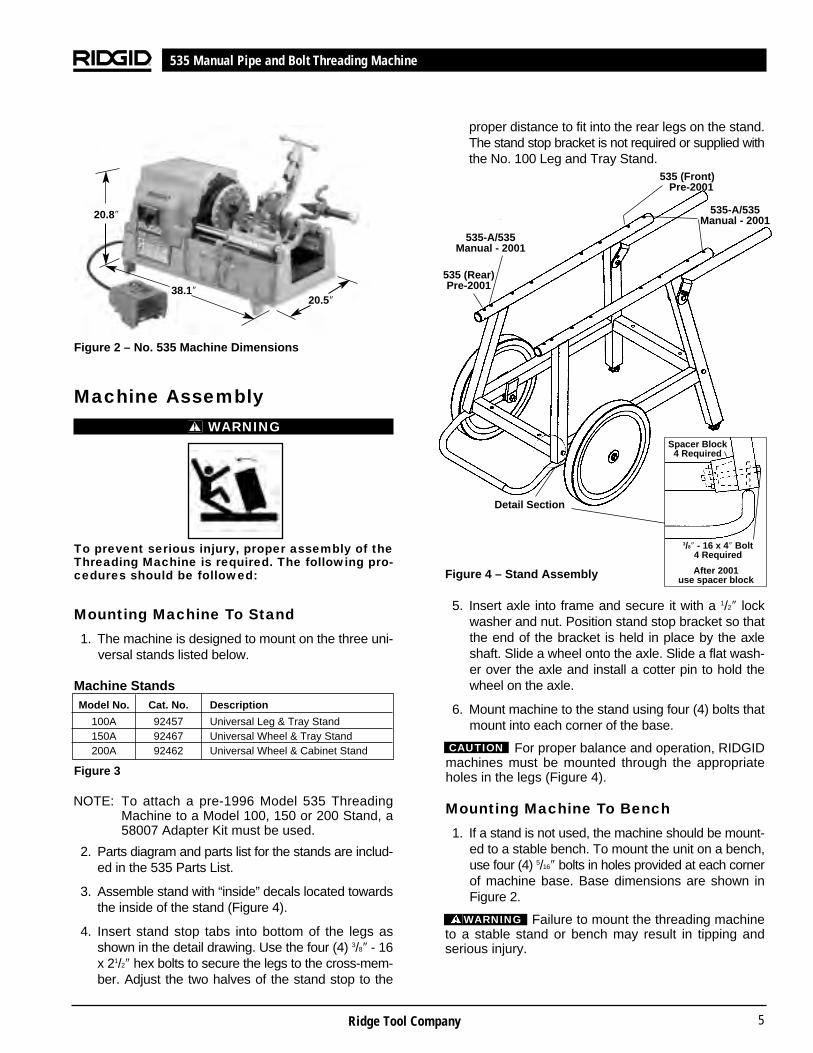
Figure 2 – No. 535 Machine Dimensions
Machine AssemblyWARNING
To prevent serious injury, proper assembly of theThreading Machine is required. The following pro-cedures should be followed:
Mounting Machine To Stand
1. The machine is designed to mount on the three uni-versal stands listed below.
Figure 3
NOTE: To attach a pre-1996 Model 535 ThreadingMachine to a Model 100, 150 or 200 Stand, a58007 Adapter Kit must be used.
2. Parts diagram and parts list for the stands are includ-ed in the 535 Parts List.
3. Assemble stand with “inside” decals located towardsthe inside of the stand (Figure 4).
4. Insert stand stop tabs into bottom of the legs asshown in the detail drawing. Use the four (4) 3/8″ - 16x 21/2″ hex bolts to secure the legs to the cross-mem-ber. Adjust the two halves of the stand stop to the
proper distance to fit into the rear legs on the stand.The stand stop bracket is not required or supplied withthe No. 100 Leg and Tray Stand.
Figure 4 – Stand Assembly
5. Insert axle into frame and secure it with a 1/2″ lockwasher and nut. Position stand stop bracket so thatthe end of the bracket is held in place by the axleshaft. Slide a wheel onto the axle. Slide a flat wash-er over the axle and install a cotter pin to hold thewheel on the axle.
6. Mount machine to the stand using four (4) bolts thatmount into each corner of the base.
For proper balance and operation, RIDGIDmachines must be mounted through the appropriateholes in the legs (Figure 4).
Mounting Machine To Bench
1. If a stand is not used, the machine should be mount-ed to a stable bench. To mount the unit on a bench,use four (4) 5/16″ bolts in holes provided at each cornerof machine base. Base dimensions are shown inFigure 2.
Failure to mount the threading machineto a stable stand or bench may result in tipping andserious injury.
535 Manual Pipe and Bolt Threading Machine
CAUTION
WARNING
Machine StandsModel No. Cat. No. Description
100A 92457 Universal Leg & Tray Stand150A 92467 Universal Wheel & Tray Stand200A 92462 Universal Wheel & Cabinet Stand
535 (Front)Pre-2001
Detail Section
535-A/535Manual - 2001
535-A/535Manual - 200120.8″
38.1″20.5″
535 (Rear)Pre-2001
3/8″ - 16 x 4″ Bolt 4 Required
Spacer Block4 Required
After 2001 use spacer block

7. Lubricate the Threading Machine if necessary accord-ing to the Maintenance Instructions.
8. Use tools and accessories that are designed for yourThreading Machine and meet the needs of yourapplication. The correct tools and accessories allowyou to do the job successfully and safely. Accessoriesdesigned for use with other equipment may be haz-ardous when used with this Threading Machine.
9. Clean any oil, grease or dirt from all handles andcontrols. This reduces the risk of injury due to a tool orcontrol slipping from your grip.
Inspect the cutting edges of your tools and dies. Ifnecessary, have them replaced prior to using theThreading Machine. Dull or damaged cutting tools anddies can lead to binding, tool breakage and poorquality threads.
10. Clean metal shavings and other debris from the chiptray of the Threading Machine. Check the level andquality of the thread cutting oil. Replace or add oil ifnecessary. Reservoir in the base will hold approxi-mately seven (7) quarts of thread cutting oil.
NOTE! Thread cutting oil lubricates and cools the threadsduring the threading operation. A dirty or poorgrade cutting oil can result in poor thread quality.
NOTE! To drain dirty oil and properly maintain the oilsystem, refer to the “Maintenance Instructions”.
Machine and Work Area Set-UpWARNING
To prevent serious injury, proper set-up of the machineand work area is required. The following proceduresshould be followed to set-up the machine:
1. Locate a work area that has the following:
• Adequate lighting.
• No flammable liquids, vapors or dust that may ignite.
• Grounded electrical outlet.
• Clear path to the electrical outlet that does notcontain any sources of heat or oil, sharp edges ormoving parts that may damage electrical cord.
• Dry place for machine and operator. Do not usethe machine while standing in water.
• Level ground.
Ridge Tool Company6
Machine InspectionWARNING
To prevent serious injury, inspect your ThreadingMachine. The following inspection proceduresshould be performed on a daily basis:
1. Make sure Threading Machine is unplugged and thedirectional switch is set to the OFF position (Figure 5).
Figure 5 – No. 535 Pipe and Bolt Threading Machine
2. Clean the speed chuck jaws with a wire brush.
3. Inspect the jaw inserts for excessive wear. Refer to theMaintenance Instructions if they need to be replaced.
4. Make sure the foot switch is present and attached tothe Threading Machine (Figure 5).
Do not operate the Threading Machinewithout a foot switch.
5. Inspect the power cord and plug for damage. If theplug has been modified, is missing the groundingpin or if the cord is damaged, do not use theThreading Machine until the cord has been replaced.
6. Inspect the Threading Machine for any broken, miss-ing, misaligned or binding parts as well as any otherconditions which may affect the safe and normaloperation of the machine. If any of these conditionsare present, do not use the Threading Machine untilany problem has been repaired.
535 Manual Pipe and Bolt Threading Machine
CenteringDevice
(Not Shown)
Chuck Handwheel
Quick or Self-Opening
Die Head
No. 820Cutter
(Standard)
No. 341Reamer
ChipPan
REV/OFF/FORSwitch
Foot Switch Carriage HandwheelLength Gauge
WARNING

9. Check the Threading Machine to insure it is operatingproperly.
• Flip the directional switch to FOR (Forward). Pressand release the foot switch. Check that the Thread-ing Machine rotates in a counterclockwise directionas you are facing the front chuck. Have the Thread-ing Machine serviced if it rotates in the wrongdirection or if the foot switch does not control itsstopping or starting.
• Depress and hold the foot switch. Inspect the mov-ing parts for misalignment, binding, odd noises orany other unusual conditions that may affect the safeand normal operation of the machine. If such con-ditions are present, have the power drive serviced.
• Flip the directional switch to REV (Reverse). Pressand release the foot switch. Check that that Thread-ing Machine rotates in a clockwise direction asyou are facing the chuck.
• Release the foot switch and flip the directionalswitch to OFF.
Operation Using Machine-Mounted Tools
WARNING
Do not wear gloves or loose clothing when operat-ing Threading Machine. Keep sleeves and jacketsbuttoned. Do not reach across the machine or pipe.
Do not use this Threading Machine if the foot switchis broken or missing. Always wear eye protection toprotect eyes from dirt and other foreign objects.
Keep hands away from rotating pipe and fittings.Stop the machine before wiping pipe threads orscrewing on fittings. Allow the machine to come toa complete stop before touching the pipe ormachine chucks.
Do not use this machine to “make-on” or “breakoff” fittings. This practice is not an intended use ofthis Threading Machine.
Installing Pipe In Threading Machine:
1. Check to insure the cutter, reamer and die head areswung to UP position.
2. Mark the pipe at the desired length if it is being cut tolength.
3. Insert the pipe into the Threading Machine so that the
Ridge Tool Company 7
2. Clean up the work area prior to setting up any equip-ment. Always wipe up any oil that may have splashedor dripped from the machine to prevent slips and falls.
3. If the workpiece extends more than four (4) feet beyondthe Threading Machine, use one or more pipe standsto prevent tipping and the oscillation of the pipe.
4. If the workpiece extends beyond the ThreadingMachine, set-up guards or barricades to create aminimum of three (3) feet of clearance around theThreading Machine and workpiece. This “safety zone”prevents others from accidentally contacting themachine or workpiece and either causing the equip-ment to tip or becoming entangled in the rotatingparts.
5. If necessary, fill the reservoir with RIDGID ThreadCutting Oil.
6. Make sure FOR/OFF/REV switch is in the OFF position.
7. Position the foot switch so that the operator cansafely control the machine, tools and workpiece. Itshould allow the operator to do the following:
• Stand facing the directional switch.
• Use the foot switch with his left foot.
• Have convenient access to the directional switch,tools and chucks without reaching across themachine.
Machine is designed for one person operation.
8. Plug the Threading Machine into the electrical outletmaking sure to position the power cord along the clearpath selected earlier. If the power cord does not reachthe outlet, use an extension cord in good condition.
WARNINGTo avoid electrical shock and electrical fires, never usean extension cord that is damaged or does not meet thefollowing requirements:
• The cord has a three-prong plug similar to shownin Electrical Safety section.
• The cord is rated as “W” or “W-A” if being usedoutdoors.
• The cord has sufficient wire thickness (14 AWGbelow 25′/12 AWG 25′ - 50′). If the wire thickness istoo small, the cord may overheat, melting the cord’sinsulation or causing nearby objects to ignite.
To reduce risk of electrical shock, keepall electrical connections dry and off the ground. Donot touch plug with wet hands.
535 Manual Pipe and Bolt Threading Machine
WARNING

Ridge Tool Company8
end to be worked or the cutting mark is located about12 inches to the front of the speed chuck jaws.
4. Insert workpieces less than 2 feet long from the frontof the machine. Insert longer pipes through eitherend so that the longer section extends out beyond therear of the Threading Machine.
To avoid equipment tip-overs, positionthe pipe supports under the workpiece.
NOTE! For plastic and coated work pieces, special jawinserts (No. 97365) should be used to preventdamaging the workpiece.
5. Tighten the rear centering device around the pipe byusing a counterclockwise rotation of the handwheel atthe rear of the Threading Machine. This prevents move-ment of the pipe that can result in poor thread quality.
6. Secure the pipe by using repeated and forceful coun-terclockwise spins of the speed chuck handwheelat the front of the Threading Machine. This action“hammers” the jaws tightly around the pipe.
Cutting Pipe with No. 820 Cutter
1. Swing reamer and die head to UP position.
2. Move pipe cutter DOWN onto pipe and move car-riage with handwheel to line up cutter wheel withmark on pipe.
NOTE! If using length gauge on machine carriage, placecutter wheel against end of stock and set point to“0”. Raise cutter to clear stock and turn carriagehandwheel until pointer is at length desired.
3. Tighten cutter feed screw handle on pipe keepingwheel aligned with the pipe. (Figure 6)
Figure 6 – Cutting Pipe with 820 Cutter
4. Assume the correct operating posture.
This will allow you to maintain proper bal-ance and to safely keep control of the machine and tools.
• Be sure you can quickly remove your foot fromthe foot switch.
• Stand facing the directional switch.
• Be sure you have convenient access to directionalswitch, tools and chucks.
• Do not reach across the machine or workpiece.
5. Flip the directional switch to FOR (Forward).
6. Grasp the pipe cutter’s feedscrew handle with bothhands.
7. Depress and hold down the foot switch with the left foot.
8. Tighten the feedscrew handle slowly and continuouslyuntil the pipe is cut. Do not force the cutter into theworkpiece.
9. Release the foot switch and remove your foot fromthe housing.
10. Swing pipe cutter back to the UP position.
Reaming Pipe with No. 341 Reamer 1. Move reamer arm into DOWN position.
2. Extend reamer by pressing latch and sliding knobtoward pipe until latch engages bar.
3. Check the directional switch to insure it is in theFOR (Forward) position. Depress and hold the footswitch down with left foot.
4. Position reamer into pipe and complete reaming byexerting pressure on handwheel. (Figure 7)
5. Retract reamer bar and return reamer to UP position.
6. Release foot switch and remove your foot from thehousing.
Figure 7 – Reaming with 341 Reamer
535 Manual Pipe and Bolt Threading Machine
WARNING
WARNING

Ridge Tool Company 9
Threading Pipe or Rod with Quick-Opening, Self-Opening or Semi-Automatic Die Head
1. Install die set. Refer to die installation procedure.
2. Swing cutter and reamer to UP position.
3. Swing die head to DOWN position with throwoutlever set to CLOSE position.
4. Check directional switch to insure it is in the FOR(Forward) position. Depress and hold the foot switchdown with left foot.
NOTE! Current 535 Machines have an automatic oilingsystem that brings oil to the work through the diehead. Machines made prior to June 1, 1996have an oil spout which must be swung to thedown position to flood dies with oil.
5. Turn carriage handwheel to bring dies against end ofpipe. Slight pressure on handwheel will start dies.(Figure 8)
Figure 8 – Threading with 535 Manual Threading Machine
6. Quick-Opening 811A Die Head (Figure 9) – Whenthread is completed, rotate throwout lever to OPENposition, retracting dies.
Self-Opening 815A Die Head (Figure 10) – When diehead trigger contacts end of pipe, throwout lever isautomatically opened.
Semi-Automatic Die Head (Figure 11) – When theend of the pipe being threaded is flush with the end ofthe number 1 die, tap the handle for the dies to re-lease the pipe.
7. Turn carriage handwheel to back die head off pipe.
8. Release the foot switch and remove your foot fromthe housing.
9. Swing die head back to UP position.
Removing Pipe From The ThreadingMachine
1. Use repeated and forceful clockwise spins of thespeed chuck handwheel at the front of the ThreadingMachine to release the workpiece from the speedchuck jaws.
2. If necessary, loosen the rear centering device usinga clockwise rotation of the handwheel at the rear ofthe Threading Machine.
3. Slide the workpiece out of the Threading Machine,keeping a firm grip on the workpiece as it clears theThreading Machine.
To avoid injury from falling parts or equip-ment tip-overs when handling long workpieces, makesure that the end farthest from the Threading Machine issupported prior to removal.
4. Clean up any oil spills or splatter on the ground sur-rounding the Threading Machine.
Left Hand Threading
An optional pump kit along with a special pipe or bolt diehead is required for left hand threading. These optionalaccessories consists of the following:Pump Kit:Model MJ-1 PumpBracket Fitting
Model 842 Quick-Opening NPT Die HeadModel 531 and 532 Quick-Opening Bolt Die Head
NOTE! Pump Kit not required on all pre-2001 535machines.
Installing Dies in Quick-Opening DieHead (Right Hand and Left Hand)
The No. 811A Universal Die Head (Figure 9) for righthand threads requires four sets of dies to thread piperanging from 1/8″ through 2″. One set of dies is requiredfor each of the following pipe size ranges: (1/8″), (1/4″and 3/8″), (1/2″ and 3/4″) and (1″ through 2″). Bolt threadingrequires a separate set of dies for each bolt size. No boltdies are available for left hand universal die heads.
1. Lay die head on bench with numbers face up.
2. Flip throwout lever to OPEN position.
3. Loosen clamp lever approximately three turns.
4. Lift tongue of clamp washer up and out of slot undersize bar. Slide throwout lever all the way to end of slotin the change die direction indicated on cam plate.
5. Remove dies from die head.
535 Manual Pipe and Bolt Threading Machine
WARNING
6. Insert new dies to mark on side of dies. Numbers 1through 4 on the dies must match numbers on thedie head.
7. Slide throwout lever back so that tongue of clamplever washer will drop in slot under size bar.
8. Adjust die head size bar until index line on link isaligned with proper size mark on size bar. For boltthreads, align underline with bolt line on size bar.
9. Tighten clamp lever.
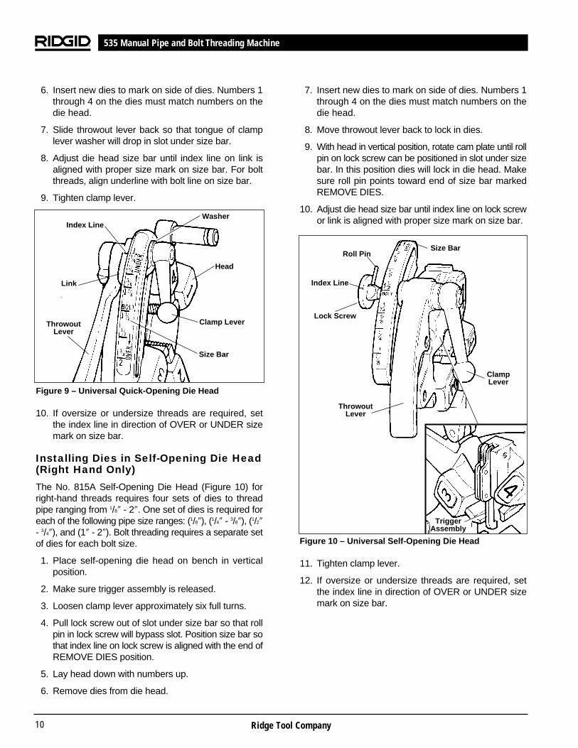
Figure 9 – Universal Quick-Opening Die Head
10. If oversize or undersize threads are required, setthe index line in direction of OVER or UNDER sizemark on size bar.
Installing Dies in Self-Opening Die Head (Right Hand Only)
The No. 815A Self-Opening Die Head (Figure 10) forright-hand threads requires four sets of dies to threadpipe ranging from 1/8″ - 2″. One set of dies is required foreach of the following pipe size ranges: (1/8″), (1/4″ - 3/8″), (1/2″- 3/4″), and (1″ - 2″). Bolt threading requires a separate setof dies for each bolt size.
1. Place self-opening die head on bench in verticalposition.
2. Make sure trigger assembly is released.
3. Loosen clamp lever approximately six full turns.
4. Pull lock screw out of slot under size bar so that rollpin in lock screw will bypass slot. Position size bar sothat index line on lock screw is aligned with the end ofREMOVE DIES position.
5. Lay head down with numbers up.
6. Remove dies from die head.
Ridge Tool Company10
7. Insert new dies to mark on side of dies. Numbers 1through 4 on the dies must match numbers on thedie head.
8. Move throwout lever back to lock in dies.
9. With head in vertical position, rotate cam plate until rollpin on lock screw can be positioned in slot under sizebar. In this position dies will lock in die head. Makesure roll pin points toward end of size bar markedREMOVE DIES.
10. Adjust die head size bar until index line on lock screwor link is aligned with proper size mark on size bar.
Figure 10 – Universal Self-Opening Die Head
11. Tighten clamp lever.
12. If oversize or undersize threads are required, setthe index line in direction of OVER or UNDER sizemark on size bar.
535 Manual Pipe and Bolt Threading Machine
Roll Pin
Index Line
Size Bar
Lock Screw
ThrowoutLever
ClampLever
TriggerAssembly
Index Line
Link
ThrowoutLever
Washer
Head
Clamp Lever
Size Bar

Installing Dies in Model 816/817 Die Heads
The Semi-Automatic Die Head (Figure 11) for right handthreads requires four sets of dies to thread pipe rangingfrom 1/8″ through 2″. One set of dies is required for eachof the following pipe size ranges: (1/8″), (1/4″ and 3/8″), (1/2″and 3/4″) and (1″ through 2″). Bolt threading requires aseparate set of of dies for each bolt size.
1. Depress handle so that camplate rests (Figure 8 –Model 816/817 Die Head) against the stop. (Asshown).
2. Lay the Die Head down flat on a table or benchwith the numbers facing up.
3. Pull up on the plunger knob and push the handle allthe way to the left.
4. Select the correct dies for the size desired. (Sizemarked on the back end or face of the dies.)
5. Numbers on the Dies must correspond with those onthe Die Head Slots. Insert Dies to the line marked onthe Dies – numbered edge up.
6. Rotate the handle back to the right so that the plungerknob pops back down flush against the Die Head.
7. To set or adjust for desired depth of cut, loosenthe screw for the desired position block size, movethe block to the right to make it Under-Size and tothe left to make it Over- Sized. When setting blocksfor new dies start with the position block on themiddle mark and adjust from there.
Figure 11 – Semi-Automatic Die Head
Ridge Tool Company 11
Checking Thread Length
(Figure 12)
1. Thread is cut to proper length when end of pipe isflush with edge of dies (Figure 12).
2. Die head is adjustable to obtain proper thread diam-eter. If possible, threads should be checked with athread ring gage (Figure 12). A proper thread is cutwhen end of pipe is plus or minus one turn of beingflush with face of ring gage.
Figure 12 – Checking Thread Length
NOTE! If a ring gage is not available, a fitting can beused. This fitting should be representative ofthose being used on the job. The pipe threadshould be cut to obtain 2 or 3 turns hand tightengagement with fitting. If pipe thread is not prop-er diameter the index line should be moved in thedirection of the OVER or UNDER size mark onsize bar. (Refer to “Installing Dies In Die Heads”).
Priming Oil Pump
Current 535 Machines have a self-priming gerotor-typepump. Machines made prior to June 1, 1996 have aModel A vane-type pump that may require priming.
WARNINGAll 535 Threading Machines made prior to June 1, 1996should have a tube extension on the oil pump primingport, as well as a top cover access hole, so the pump canbe primed without removing the top cover of the machine.This will prevent the operator from contacting the internalgearing of the machine which could result in serious injury.
If your older-style machine has a Model A Vane-Type pumpand does not have a priming port, contact the Ridge ToolCompany at 1-800-519-3456 or e-mail [email protected] regarding a retrofit policy.
535 Manual Pipe and Bolt Threading Machine
W W
D D D
Die
Pipe
Die
Pipe
A - Full Width Die Thread
Starting to Cut Thread
Flush(Basic Size)
One Turn Large(Maximum Size)
One Turn Small(Minimum Size)
Thin RingGage
Completed Thread
Die FlushWith End
of Pipe
B - Checking Threads Within Pipe Gage
Handle
Plunger Knob
Size Block
Ridge Tool Company12
To prime the Model A Pump, the following procedureshould be followed:
1. Remove button plug located on cover.
2. Remove primer screw through opening with allenwrench.
3. Fill pump with oil.
4. Replace primer screw and button plug before startingmachine or pump will drain itself immediately.
NOTE! If machine must be primed on a frequent basis,it is an indication the pump is in need of repair.
Operation Instructions UsingGeared Threaders
WARNING
Do not wear gloves or loose clothing when oper-ating Threading Machine. Keep sleeves and jack-ets buttoned. Do not reach across the machine,geared threader or drive shaft.
Do not use this Threading Machine if the foot switchis broken or missing. Always wear eye protection toprotect eyes from dirt and other foreign objects.
To prevent tipping, proper set-up of the ThreadingMachine and Geared Threader is required. Followinstructions carefully.
Geared Threaders weigh 95 to 160 pounds. Two (2)persons should be used to lift these threaders.
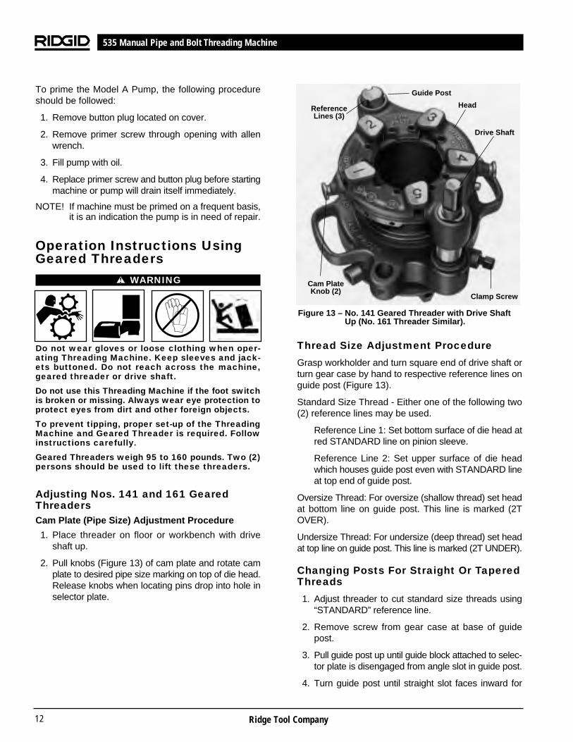
Adjusting Nos. 141 and 161 GearedThreadersCam Plate (Pipe Size) Adjustment Procedure
1. Place threader on floor or workbench with driveshaft up.
2. Pull knobs (Figure 13) of cam plate and rotate camplate to desired pipe size marking on top of die head.Release knobs when locating pins drop into hole inselector plate.
Thread Size Adjustment Procedure
Grasp workholder and turn square end of drive shaft orturn gear case by hand to respective reference lines onguide post (Figure 13).
Standard Size Thread - Either one of the following two(2) reference lines may be used.
Reference Line 1: Set bottom surface of die head atred STANDARD line on pinion sleeve.
Reference Line 2: Set upper surface of die headwhich houses guide post even with STANDARD lineat top end of guide post.
Oversize Thread: For oversize (shallow thread) set headat bottom line on guide post. This line is marked (2TOVER).
Undersize Thread: For undersize (deep thread) set headat top line on guide post. This line is marked (2T UNDER).
Changing Posts For Straight Or TaperedThreads
1. Adjust threader to cut standard size threads using“STANDARD” reference line.
2. Remove screw from gear case at base of guidepost.
3. Pull guide post up until guide block attached to selec-tor plate is disengaged from angle slot in guide post.
4. Turn guide post until straight slot faces inward for
535 Manual Pipe and Bolt Threading Machine
Guide Post
Head
Drive Shaft
Clamp Screw
Cam PlateKnob (2)
ReferenceLines (3)
Figure 13 – No. 141 Geared Threader with Drive ShaftUp (No. 161 Threader Similar).

535 Manual Pipe and Bolt Threading Machine
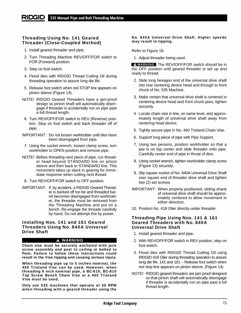
Installing No. 141 Geared Threader(Close-Coupled Method)
Threading pipe with a No. 141 Geared Threader (closed-coupled method) requires a Drive Bar cat. #42405, aRIDGID Support Stand, and a Drive Link Assembly Kit cat.#42415 (Old Style Carriage) or cat. #16723 (High Clear-ance Carriage).
The REV/OFF/FOR switch should be inthe OFF position until geared threader is installed andready to thread.
1. Remove die head from machine.
2. Raise cutter and reamer out of way and move car-riage to front.
3. Open front chuck jaws and workholder jaws.
4. Install No. 844 Drive Bar (Figure 16) onto 141 GearedThreader Drive Shaft and tighten two (2) set screwsusing 5/16″ socket head wrench.
Figure 15 – No. 844 Drive Bar and Drive Link Installed
5. Insert Drive Link into loop hole on 141 GearedThreader. Using a 1/4″ socket head wrench, tightenSet Screw only enough to retain Drive Link, allowingit to swing freely.
NOTE! On 535s with high clearance carriage a levelingsaddle (included with cat. #16723) must beused in conjunction with Model 141 GearedThreader. (Figure 17 A and B)
6. Using two persons, Raise 141 Geared Threader and seton carriage. Resting 141 Geared Threader on car-riage, move carriage rearward and engage No. 844Drive Bar in 535 front chuck and rear centering device.
7. Align grooves on No. 844 Drive Bar with front chuckjaws and grip securely using chuck handwheel andworkholder centering head.
Ridge Tool Company 13
straight thread, or tapered slot inward for taperedthread. Figure 14 shows guide post set to cut taperedthread.
5. Engage guide block in slot and push guide postdown into position.
6. Replace guide post screw.
Unit is now set to cut straight threads (NPSM or BSPP)or taper threads (NPT or BSPT).
Changing Die Set
1. Remove stop screw (Figure 14) from selector plate.
2. Pull Knobs (Figure 13) and rotate cam plate to CDmark on top of die head.
3. Remove worn die set (Figure 14) and insert new die set.
IMPORTANT: Be sure to replace complete die set.Die numbers must correspond with slotnumbers.
4. Rotate cam plate to original position and replacestop screw.
NOTE! If it becomes necessary to remove or replace theguide block, the stamped number E-1997 onguide block must be AGAINST selector plate. Ifstamped number is visible you will cut an UN-DERSIZE thread.
Figure 14 – No. 141 Geared Threader showing Pinion Sleeve and Guide Post Reference Lines
Die (Set of 5)GuideBlock
2T UnderLine
StandardLIne
2T OverLine
Screw
Guide Post
Gear Case
SelectorPlate
Die Head
StopScrew
Red StopLine
StandardLine
PinionSleeve
WARNING
141 Geared Threader
Set Screw (2) No. 844 Drive Bar
Drive Shaft
Set Screw
Drive Link

535 Manual Pipe and Bolt Threading Machine
Be sure that No. 844 Drive Bar is prop-erly engaged and secured.
8. Supporting 141 Geared Threader, move carriageand fully engage Drive Link Assembly in die headmounting hole on carriage. Tighten Set Screw.
9. Attach multiposition oil spout to drive link (Figure16A and 16B).
If pipe extends beyond machine bed, itshould have a pipe support. Be sure that adjusting col-lar on pipe support stand is locked securely.
10. Support pipe with a pipe support. Position supportapproximately 21/2 feet from threader.
11. Insert pipe in threader and center end of pipe inthroat of dies. Tighten workholder with socket wrench.
12. Tighten clamp screw securely with socket wrench.
Figure 16A – 141 Geared Threader Close-Coupled ToNew-Style 535 using Drive Link. Note OilSpout Attached To Link.
Ridge Tool Company14
Figure 16B – 141 Geared Threader Closed-Coupled toNew-Style 535 Showing Position Of OilSpout On Workpiece.
Figure 17A – Geared Threader Saddle Adapter
Figure 17B – Saddle Adapted Mounted on 535 Carriage
WARNING
WARNING
Ridge Tool Company 15
535 Manual Pipe and Bolt Threading Machine
Threading Using No. 141 GearedThreader (Close-Coupled Method)
1. Install geared threader and pipe.
2. Turn Threading Machine REV/OFF/FOR switch toFOR (Forward) position.
3. Step on foot switch.
4. Flood dies with RIDGID Thread Cutting Oil duringthreading operation to assure long die life.
5. Release foot switch when red STOP line appears onpinion sleeve (Figure 14).
NOTE! RIDGID Geared Threaders have a jam-proofdesign so pinion shaft will automatically disen-gage if threader is accidentally run on pipe pasta full thread length.
6. Turn REV/OFF/FOR switch to REV (Reverse) posi-tion. Step on foot switch and back threader off ofpipe.
IMPORTANT: Do not loosen workholder until dies havebeen disengaged from pipe.
7. Using the socket wrench, loosen clamp screw, turnworkholder to OPEN position and remove pipe.
NOTE!: Before threading next piece of pipe, run thread-er head beyond STANDARD line on pinionsleeve and then back to STANDARD line. Thismovement takes up slack in gearing for imme-diate response when cutting next thread.
8. Turn REV/OFF/FOR switch to OFF position.
IMPORTANT: If, by accident, a RIDGID Geared Thread-er is backed off too far and threaded bar-rel becomes disengaged from workhold-er, the threader must be removed fromthe Threading Machine and put on abench. Re-engage the threads carefullyby hand. Do not attempt this by power.
Installing Nos. 141 and 161 GearedThreaders Using No. 840A UniversalDrive Shaft
WARNINGChain vise must be securely anchored with jackscrew assembly and post to ceiling or bolted tofloor. Failure to follow these instructions couldresult in the Vise tipping and causing serious injury.
When threading pipe up to 5 inches nominal, the450 Tristand Vise can be used. However, whenthreading 6 inch nominal pipe, a BC-610, BC-810Top Screw Bench Chain Vise or a 460 TristandVise must be used.
Only use 535 machines that operate at 36 RPMwhen threading with a geared threader using the
No. 840A Universal Drive Shaft. Higher speedsmay result in tipping.
Refer to Figure 18.
1. Adjust threader being used.
The REV/OFF/FOR switch should be inthe OFF position until geared threader is set up andready to thread.
2. Slide long hexagon end of the universal drive shaftinto rear centering device head and through to frontchuck of No. 535 Machine.
3. Make certain that universal drive shaft is centered incentering device head and front chuck jaws; tightensecurely.
4. Locate chain vise in line, on same level, and approx-imately length of universal drive shaft away fromcentering head device.
5. Tightly secure pipe in No. 460 Tristand Chain Vise.
6. Support long piece of pipe with Pipe Support.
7. Using two persons, position workholder so that ajaw is on top center and slide threader onto pipe.Carefully center end of pipe in throat of dies.
8. Using socket wrench, tighten workholder clamp screw(Figure 13) securely.
9. Slip square socket of No. 840A Universal Drive Shaftover square end of threader drive shaft and tightentwo (2) set screws.
IMPORTANT: When properly positioned, sliding shankof universal drive shaft should be approx-imately centered to allow movement ineither direction.
10. Position No. 418 Oiler directly under threader.
Threading Pipe Using Nos. 141 & 161Geared Threaders with No. 840AUniversal Drive Shaft1. Install geared threader and pipe.
2. With REV/OFF/FOR switch in REV position, step onfoot switch.
3. Flood dies with RIDGID Thread Cutting Oil usingRIDGID 418 Oiler during threading operation to assurelong die life. 141 and 161 – Release foot switch whenred stop line appears on pinion sleeve. (Figure 14)
NOTE! RIDGID geared threaders are jam proof designedso that pinion shaft will automatically disengageif threader is accidentally run on pipe past a fullthread length.
WARNING

No. 819 Nipple ChuckThe RIDGID No. 819 Nipple Chuck is a quick and easytool for holding short and close nipples or studs forthreading.
Capacity: 1/8″ to 2″ Standard Pipe (NPT) 1/4″ to 2″ Bolts or Studs UNC or UNF
Short or Close Nipple ThreadingProcedure
The REV/OFF/FOR switch should be inthe OFF position until nipple chuck is set up and readyto thread.
1. Grip pipe in machine chuck. Thread and ream oneend and cut nipple to desired length.
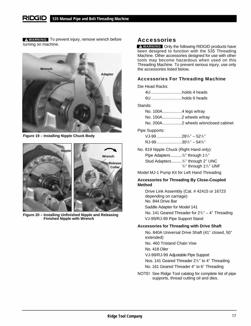
2. Place nipple chuck body (Figure 19) in ThreadingMachine chuck, gripping jaw grooves. Tighten chuckwith snap spin of handwheel.
3. Position insert with small end toward chuck body for1/8″ to 3/4″ pipe; large end toward chuck body for 1″pipe; no insert required for 11/4″ pipe and up.
4. Select proper size nipple chuck adapter and screwinto nipple chuck (Figure 19) by hand. Tighten withwrench provided with nipple chuck.
To prevent injury, remove wrench beforeturning on machine.
5. Screw nipple (Figure 20) threaded on one end intoadapter by hand. Turn directional switch to ON andpress down on foot switch. Ream and thread otherend.
6. Insert pin on end of wrench (Figure 20) into one ofholes in nipple chuck release collar and turn. Removethreaded nipple by hand.
Ridge Tool Company16
535 Manual Pipe and Bolt Threading Machine
4. Turn REV/OFF/FOR switch to FOR (forward) positionto back geared threader off pipe.
NOTE! Do not loosen workholder until dies have beendisengaged from pipe.
141 and 161 – Step on foot switch and reversethreader one or two revolutions. Pull knobs (Figure13) and rotate cam plate as far as it will go towardsCD mark on head to disengage dies.
5. Turn REV/OFF/FOR switch to OFF position.
6. Loosen two (2) set screws (Figure 18) and removeuniversal drive shaft from threader.
NOTE! Do not loosen workholder until dies have beendisengaged from pipe.
141 and 161 – Loosen jaw clamp screw (Figure 13)and turn workholder to OPEN position. Removethreader.
7. Loosen chain vise and remove pipe.
8. Open centering device head to release No. 840AUniversal Drive Shaft.
NOTE! If by accident, a RIDGID Geared Threader isbacked off too far and threaded barrel becomesdisengaged from workholder, the threader mustbe put on a bench and the threads re-engagedcarefully by hand. Do not attempt this by power.
Figure 18 – Threading Pipe using No. 840A UniversalDrive Shaft
WARNING
WARNING
Pipe Adapters Stud Adapters1/8″, 1/4″, 3/8″, 1/2″, 1/4″ to 2″ UNC
3/4″, 1″, 11/4″, 11/2″ 1/4″ to 11/2″ UNF
No. 418 Oiler
No. 141Geared Threader
No. 840ADrive Shaft
No. 460 TristandChain Vise
SetScrew (2)
Foot Switch
Centering Head
Ridge Tool Company 17
AccessoriesOnly the following RIDGID products have
been designed to function with the 535 ThreadingMachine. Other accessories designed for use with othertools may become hazardous when used on thisThreading Machine. To prevent serious injury, use onlythe accessories listed below.
Accessories For Threading Machine
Die Head Racks:4U ...........................holds 4 heads6U ...........................holds 6 heads
Stands:No. 100A.................4 legs w/trayNo. 150A.................2 wheels w/trayNo. 200A...................2 wheels w/enclosed cabinet
Pipe Supports:VJ-99 ......................281/4″ – 521/2″
RJ-99 ......................301/2″ – 543/4″
No. 819 Nipple Chuck (Right Hand only):Pipe Adapters...........1/8″ through 11/2″
Stud Adapters..........1/4″ through 2″ UNC1/4″ through 11/2″ UNF
Model MJ-1 Pump Kit for Left Hand Threading
Accessories for Threading By Close-CoupledMethod
Drive Link Assembly (Cat. # 42415 or 16723depending on carriage) No. 844 Drive Bar Saddle Adapter for Model 141No. 141 Geared Threader for 21/2″ – 4″ ThreadingVJ-99/RJ-99 Pipe Support Stand
Accessories for Threading with Drive Shaft
No. 840A Universal Drive Shaft (41″ closed, 50″extended)No. 460 Tristand Chain ViseNo. 418 OilerVJ-99/RJ-99 Adjustable Pipe SupportNos. 141 Geared Threader 21/2″ to 4″ ThreadingNo. 161 Geared Threader 4″ to 6″ Threading
NOTE! See Ridge Tool catalog for complete list of pipesupports, thread cutting oil and dies.
535 Manual Pipe and Bolt Threading Machine
To prevent injury, remove wrench beforeturning on machine.
Figure 19 – Installing Nipple Chuck Body
Figure 20 – Installing Unfinished Nipple and ReleasingFinished Nipple with Wrench
Nipple
ReleaseCollar
Wrench
Adapter
Wrench
WARNING
WARNING

Ridge Tool Company18
535 Manual Pipe and Bolt Threading Machine
Maintenance InstructionsWARNING
Make sure machine is unplugged from powersource before performing maintenance or mak-ing any adjustment.
Lubrication
Proper lubrication is essential to trouble-free operationand long life of Power Drive.
1. Remove four (4) cover mounting screws and removethe cover.
2. Use grease gun to apply grease to the shaft bearinggrease fittings every 2 to 6 months, depending uponfrequency of machine use.
3. Apply moderate coat of lubricating grease on largegear each time bearings are lubricated.
Do not operate the threading machinewith cover off. Always replace cover immediately afterlubricating machine.
Oil System Maintenance
To help assure proper operation of threading machine,keep oil system clean, as follows:
1. Replace thread cutting oil when it becomes dirty orcontaminated. To drain the oil, position a containerunder drain plug and remove plug.
2. Keep oil filter screen clean to assure proper flow orclean oil to work. Oil filter screen is located in the bot-tom of oil reservoir. To clean filter screen, loosenthe screw that secures filter to base and pull filter from
Die Heads and DiesPipe Bolt
Model Capacity Capacity Dies Opening Operation811A NPT 1/8″ - 2″ 1/4″ - 2″ Universal Quick R.H.815A NPT 1/8″ - 2″ 1/4″ - 2″ Universal Self R.H.842 NPT 1/4″ - 2″ — Universal Quick L.H.816 NPT 1/8″ - 3/4″ 1/4″ - 2″ Universal TAP R.H.817 NPT 1″ - 2″ 1/4″ - 2″ Universal TAP R.H.
811A BSPT 1/8″ - 2″ 1/4″ - 2″ Universal Quick R.H.815A BSPT 1/8″ - 2″ 1/4″ - 2″ Universal Self R.H.
531 Bolt — 1/4″ - 1″ 500B Quick R.H./L.H.532 Bolt — 11/8″ - 2″ 500B Quick R.H./L.H.
Universal Pipe Die NPT NPSM(Catalog Numbers) 1/8″ 1/4″ - 3/8″ 1/2″ - 3/4″ 1″ - 2″ 1/8″ 1/4″ - 3/8″ 1/2″ - 3/4″ 1″ - 2″H.S. R.H. 47755 47760 47765 47770 47845 47850 47855 47860H.S. L.H. — 47810 47815 47820 — — — 70775H.S. for S.S. R.H. 47775 47780 47785 47790 — — — —H.S. for C.I. R.H. — — — 70740 — — — —H.S. for PVC R.H. — — 70745 70750 — — — —H.S. for Coated R.H. — — — 31822 — — — —
Universal Pipe Die BSPT BSPP(Catalog Numbers) 1/8″ 1/4″ - 3/8″ 1/2″ - 3/4″ 1″ - 2″ 1/8″ 1/4″ - 3/8″ 1/2″ - 3 /4″ 1″ - 2″H.S. R.H. 66750 66755 66760 66765 66795 66800 66805 66810H.S. L.H. — 66840 66845 66850 — — 66870 66875H.S. for S.S. R.H. 66770 66775 66780 66785 66815 66820 66825 66830H.S. for S.S. L.H. — 66855 66860 66865 — — — —H.S. for PVC R.H. — — 70755 70760 — — 70765 70770H.S. for Coated R.H. — — — 31837 — — — —
Note: BSPT and BSPP Dies require a British Model Die HeadNote: L.H. operation of the 1822-I requires special set upNote: High Speed Dies are recommended for threading 1″ - 2″ pipe at 45 RPMUniversal Bolt Dies for 811A, 815A, 816 and 817 Die Heads
Over 90 sets available from 1/4″ to 2″, Alloy or High Speed.Right Hand only in UNC, UNF and BSW thread forms.
500B Bolt Dies for 531 and 532 Die HeadsOver 200 sets for the 531 Bolt Die HeadOver 150 sets for the 532 Bolt Die Head
Mono Dies for Mono (A Series) Die Heads
WARNING

Service and RepairWARNING
Service and repair work on this Threading Machine mustbe performed by qualified repair personnel. Machineshould be taken to a RIDGID Independent AuthorizedService Center or returned to the factory. All repairsmade by Ridge service facilities are warranted againstdefects in material and workmanship.
When servicing this machine, only identical replacementparts should be used. Failure to follow these instructionsmay create a risk of electrical shock or other seriousinjury.
If you have any questions regarding the service or repairof this machine, call or write to:
Ridge Tool CompanyTechnical Service Department400 Clark StreetElyria, Ohio 44035-6001Tel: (800) 519-3456E-Mail: [email protected]
For name and address of your nearest IndependentAuthorized Service Center, contact the Ridge ToolCompany at (800) 519-3456 or http://www.ridgid.com
oil line. Clean filter screen in solvent and blow out withcompressed air if available. Do not operate machinewith oil filter screen removed.
NOTE! RIDGID Thread Cutting Oil produces high qualitythreads and maximizes die life. For informationconcerning its use and handling, refer to the labelson the oil containers. Disposal of the oil should bein accordance with government regulations.
Jaw Insert Replacement NOTE! When teeth on jaw inserts become worn and fail
to hold pipe or rod during operation, replaceentire set of jaw inserts. Clean teeth of jaw in-serts daily with wire brush.
1. Place screwdriver in insert slot and turn 90 degreesin either direction.
2. Place insert sideways on locking pin and pressdown as far as possible.
3. Hold insert down firmly with screwdriver, turn so teethface up.
Figure 21 – Jaw Insert Replacement
Motor Brush Replacement
Check motor brushes every six (6) months and replacebrushes when they are worn to less than 1/2″. If com-mutator is worn, turn outer dimensions of commutatorand undercut mica before replacing brushes.
Machine Storage
Motor-driven equipment must be keptindoors or well covered in rainy weather. Store themachine in a locked area that is out of reach of childrenand people unfamiliar with threading machines. Thismachine can cause serious injury in the hands of un-trained users.
Ridge Tool Company 19
535 Manual Pipe and Bolt Threading Machine
WARNING
To Remove To Replace
Screw Driver
InsertLocking
PinTeeth
PRESSDOWN➔

Ridge Tool Company20
535 Manual Pipe and Bolt Threading Machine
1101 Motor (115V)2301 Motor (230V)1101A Motor (115V)
European Wiring Diagram
White (Blue)Black (Brown)
Green (Green/Yellow)
115V25-60 Hz IEC Standard
Black
Gre
en
Wh
ite
Bla
ckG
reen
/Yel
low
Bla
ck
Suppressor
Yellow
WhiteRed
Blue
OFF
FWD
REV
Foot Switch
Wiring Diagrams
MARRON
ROJOBLANCO
Related Documents