315 E 2.905.3.0/02.14 5 5.3 HEAVY DUTY SERIES SIZE 2/3/6 CONTENTS PGI102 Ordering Code 5.3.1 Heavy Duty Series Technical Information 5.3.2 Specifications 5.3.3 Hydraulic fluids 5.3.4 Viscosity range 5.3.5 Temperature range 5.3.6 Seals 5.3.7 Filtration 5.3.8 Installation notes 5.3.9 Multiple pumps Performance Data 5.3.10 PGI102 Dimensions 5.3.11 PGI102-2 5.3.12 PGI102-3 5.3.13 PGI102-6 5.3.14 Double pump PGI102-2 + PGI102-2 5.3.15 Double pump PGI102-3 + PGI102-3 Double pump PGI102-2 + PGI102-2 5.3.16 Double pump PGI102-6 + PGI102-6 Double pump PGI102-6 + PGI102-3 Double pump PGI102-6 + PGI102-2

Welcome message from author
This document is posted to help you gain knowledge. Please leave a comment to let me know what you think about it! Share it to your friends and learn new things together.
Transcript

315
E 2
.905
.3.0
/02.
14
5
5.3 HEAVY DUTY SERIES SIZE 2/3/6
CONTENTS PGI102
Ordering Code 5.3.1 Heavy Duty Series
Technical Information 5.3.2 Specifications
5.3.3 Hydraulic fluids
5.3.4 Viscosity range
5.3.5 Temperature range
5.3.6 Seals
5.3.7 Filtration
5.3.8 Installation notes
5.3.9 Multiple pumps
Performance Data 5.3.10 PGI102
Dimensions 5.3.11 PGI102-2
5.3.12 PGI102-3
5.3.13 PGI102-6
5.3.14 Double pump PGI102-2 + PGI102-2
5.3.15 Double pump PGI102-3 + PGI102-3
Double pump PGI102-2 + PGI102-2
5.3.16 Double pump PGI102-6 + PGI102-6
Double pump PGI102-6 + PGI102-3
Double pump PGI102-6 + PGI102-2

316
E 2
.905
.3.0
/02.
14
PGI102 – 2 – 004 – R K 0 3 – 10 – XXXX
Heavy Duty Series
Size
Displacement PGI102-2- PGI102-3- PGI102-6-004 3.8 cm³/rev 014 14.6 cm³/rev 040 40.8 cm³/rev005 5.4 cm³/rev 016 16.0 cm³/rev 050 50.6 cm³/rev006 6.4 cm³/rev 020 20.0 cm³/rev 064 65.3 cm³/rev008 7.9 cm³/rev 025 24.8 cm³/rev 080 80.0 cm³/rev011 10.9 cm³/rev 032 32.1 cm³/rev 100 101.2 cm³/rev013 13.3 cm³/rev 040 40.1 cm³/rev 125 125.7 cm³/rev016 15.8 cm³/rev 050 50.3 cm³/rev 160 160.1 cm³/rev019 19.3 cm³/rev 064 64.6 cm³/rev 200 200.9 cm³/rev022 22.2 cm³/rev 250 249.9 cm³/rev025 25.2 cm³/rev
Shaft rotation (viewed from shaft end) R Clockwise L Anti-clockwise
Shaft A Parallel shaft with key (only PGI102-3-064) K Keyed shaft with through drive (not PGI102-3-064) P Splined shaft with through drive (only for multiple pumps)
Mounting flange 0 SAE J744 82-2 A - Ø 82.55 mm (size 2) 2 SAE J744 101-2 B - Ø 101.6 mm (size 3) SAE J744 152-2 D - Ø 152.4 mm (size 6) 3 Direct mounting (only on multiple pumps) 5 VDMA (on request)
Ports 3 SAE flange 0 Suction port sealed (only on multiple pumps)
Series
Modification number XXXX Determined by manufacturer
ORDERING CODE5.3.1 Heavy Duty Series
317
E 2
.905
.3.0
/02.
14
5
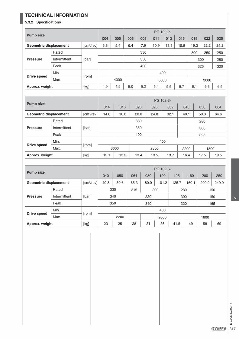
TECHNICAL INFORMATION5.3.2 Specifications
Pump sizePGI102-2-
004 005 006 008 011 013 016 019 022 025
Geometric displacement [cm3/rev] 3.8 5.4 6.4 7.9 10.9 13.3 15.8 19.3 22.2 25.2
Pressure
Rated
[bar]
330 300 250 250
Intermittent 350 300 280
Peak 400 325 300
Drive speedMin.
[rpm]400
Max. 4000 3600 3000
Approx. weight [kg] 4.9 4.9 5.0 5.2 5.4 5.5 5.7 6.1 6.3 6.5
Pump sizePGI102-3-
014 016 020 025 032 040 050 064
Geometric displacement [cm3/rev] 14.6 16.0 20.0 24.8 32.1 40.1 50.3 64.6
Pressure
Rated
[bar]
330 280
Intermittent 350 300
Peak 400 325
Drive speedMin.
[rpm]400
Max. 3600 2800 2200 1800
Approx. weight [kg] 13.1 13.2 13.4 13.5 13.7 16.4 17.5 19.5
Pump sizePGI102-6-
040 050 064 080 100 125 160 200 250
Geometric displacement [cm3/rev] 40.8 50.6 65.3 80.0 101.2 125.7 160.1 200.9 249.9
Pressure
Rated
[bar]
330 315 300 280 150
Intermittent 340 330 300 150
Peak 350 340 320 165
Drive speedMin.
[rpm]400
Max. 2200 2000 1800
Approx. weight [kg] 23 25 28 31 36 41.5 49 58 69
318
E 2
.905
.3.0
/02.
14
5.3.3 Hydraulic fluids
The pump series is designed for use with
HLP Hydraulic oil
Before using synthetic fluids, please contact HYDAC:
HEES, HETG Environmentally-friendly operating fluids
HFC Water glycol
HFD-U Fire-resistant fluids based on polyolester
HFD-R Fire-resistant fluids based on phosphate ester
5.3.5 Temperature range
Temperature range -20 to 100 °CMaximum ambient temperature -40 to 80 °CMaximum fluid temperature -40 to 120 °C
Before using synthetic fluids, please contact HYDAC.
5.3.4 Viscosity range
cSt (mm2/s)
Minimum viscosity: 10
Normal operating viscosity:
10 - 300
Maximum viscosity: 2,000
5.3.7 Filtration
For maximum service life of the pump and system components, the system should be protected from contamination by effective filtration.
Cleanliness class:
20/ 18/ 15 to ISO 4406:1999 or Class 9 to NAS 1638 or cleaner.To ensure a longer service life, cleanliness class:
18/16/13 to ISO 4406:1999 or Class 9 to NAS 1638.
5.3.9 Multiple pumps
Internal gear pumps in the PGI102 series can be combined to form double or triple gear pumps (for larger units please contact HYDAC). The performance characteristics for single pumps generally applies but the following points must be taken into consideration:
• It is recommended that the pump with the largest load be placed on the drive side.
• The maximum drive speed of the multiple pump is limited to the lowest speed of the individual pumps.
• The maximum drive and through drive torques must be checked for each stage.• The torques generated by the pump unit can be calculated using the following formula:
Mmax =∆p1 • V1 +
∆p2 • V2 +∆p3 • V3
20 • π•ηmh 20 • π•ηmh 20 • π•ηmh
Maximum drive and through drive torques
Size Drive torque Though drive torque
Rated Max. Rated Max.
2 160 Nm 200 Nm 120 Nm 130 Nm
3 325 Nm 400 Nm 230 Nm 240 Nm
6 1100 Nm 1300 Nm 850 Nm 900 Nm
• Common suction port, separate drain ports
• There is no sealing between the individual pump stages
• PGI101 and PGI102 can be combined to form multiple units.
If a double internal gear pump combination is installed vertically in V1 arrangement and there is no guarantee that the primary stage is completely submerged in the oil in the tank under all operating conditions, we recommend that only the suction port of the primary stage is used to supply the oil to the double internal gear pump combination.
In this case the common suction port of the double internal gear pump combination and the suction port of the secondary stage must be plugged.
In addition, the suction port of the primary stage must be fitted with an anti-siphon to ensure the fluid remains in the double internal gear pump combination after a lengthy stoppage.
For triple and multiple internal gear pump combinations, please contact HYDAC.
5.3.8 Installation notes
A. MountingThe pump can be installed horizontally or vertically with the shaft at the top. If the pump is installed on the tank or above the oil level, the distance between the pump inlet and the oil level should not exceed 1 metre.
When installing a HYDAC pump always ensure that the fluid remains in the pump during stoppages.
B. Suction pipeIf the pump is installed above the oil level, particular attention must be paid to the suction pressure. The cross-section of the suction pipe must be equal to or larger than the cross-section of the pump port. The suction pressure must be kept within the values specified.
Minimum suction pressure: 0.8 bar abs.
Maximum suction pressure: 2.0 bar abs.
- When installing a HYDAC pump always ensure that the fluid remains in the pump during stoppages.. C. DriveUse a flexible coupling whenever possible. There must not be any radial or axial forces on the pump shaft. The maximum misalignment of the shafts is 0.2 mm and the angular deviation must be less than 0.2°.
5.3.6 Seals
The pump series is equipped with FPM (Viton) seals. Before using synthetic fluids, please contact HYDAC.

319
E 2
.905
.3.0
/02.
14
5
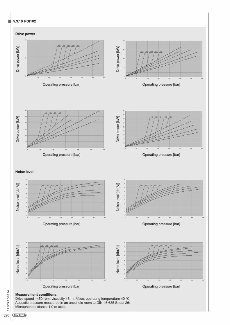
PERFORMANCE DATA5.3.10 PGI102
Out
put fl
ow [l
/min
]
Operating pressure [bar]
Operating pressure [bar]
Operating pressure [bar]
Operating pressure [bar]
Out
put fl
ow [l
/min
]
Effi
cien
cy [%
]
Effi
cien
cy [%
]
Output flow
Efficiency
50
100
150
0 50 100 150 200 250 300 350
040 050 064 080 100
100
200
300
400
003052002051001050
250 200 160 125
70%
80%
90%
100%
0 50 100 150 200 250 300 350
100 080 064 050 040
100 080 064 050 040
70%
80%
90%
100%
0 50 100 150 200 250 300
250 200 160 125
250 200 160 125
Measurement conditions: Drive speed 1450 rpm, viscosity 46 mm²/sec, operating temperature 40 °C Acoustic pressure measured in an anechoic room to DIN 45 635 Sheet 26; Microphone distance 1.0 m axial.
Out
put fl
ow [l
/min
]
Operating pressure [bar]
Operating pressure [bar]
Operating pressure [bar]
Operating pressure [bar]
Out
put fl
ow [l
/min
]
Effi
cien
cy [%
]
Effi
cien
cy [%
]
15
20
25
30
35
40
0 50 100 150 200 250 300 350
013 016 019 022 025
0
5
10
15
20
0 50 100 150 200 250 300 350
004 005 006 008 011
70%
80%
90%
100%
0 50 100 150 200 250 300 350
013 016 019 022 025
013 016 019 022 025
70%
80%
90%
100%
0 50 100 150 200 250 300 350
004 005 006 008 011
004 005 006 008 011
320
E 2
.905
.3.0
/02.
14
5.3.10 PGI102
Operating pressure [bar]
Operating pressure [bar]
Measurement conditions: Drive speed 1450 rpm, viscosity 46 mm²/sec, operating temperature 40 °C Acoustic pressure measured in an anechoic room to DIN 45 635 Sheet 26; Microphone distance 1.0 m axial.
Operating pressure [bar]
Operating pressure [bar]
Driv
e po
wer
[kW
]
Driv
e po
wer
[kW
]
Noi
se le
vel [
db(A
)]
Noi
se le
vel [
db(A
)]
Drive power
Noise level
0
5
10
15
20
0 50 100 150 200 250 300 350
016013 019 022 025
0
5
10
0 50 100 150 200 250 300 350
004 005 006 008 011
47
49
51
53
55
57
59
61
63
65
0 50 100 150 200 250 300 350
013 016 019 022 025
44
46
48
50
52
54
56
58
60
0 50 100 150 200 250 300 350
004 005 006 008 011
Operating pressure [bar]
Operating pressure [bar]
Operating pressure [bar]
Operating pressure [bar]
Driv
e po
wer
[kW
]
Driv
e po
wer
[kW
]
Noi
se le
vel [
db(A
)]
Noi
se le
vel [
db(A
)]
0
10
20
30
40
50
60
70
80
90
0 50 100 150 200 250 300 350
040 050 064 080 100
0
20
40
60
80
100
120
003052002051001050
125 160 200 250
60
62
64
66
68
70
72
74
76
0 50 100 150 200 250 300 350
040 050 064 080 100
62
64
66
68
70
72
74
76
003052002051001050
125 160 200 250
321
E 2
.905
.3.0
/02.
14
5
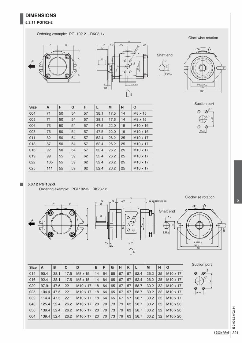
DIMENSIONS5.3.11 PGI102-2
Ordering example: PGI 102-2-...RK03-1x
5.3.12 PGI102-3 Ordering example: PGI 102-3-...RK23-1x
bei NG 064: 76 mm
Clockwise rotation
Clockwise rotation
Shaft end
Shaft end
Suction port
Suction portSize A B C D E F G H K L M N O
014 90.4 38.1 17.5 M8 x 15 14 64 65 67 57 52.4 26.2 25 M10 x 17
016 92.4 38.1 17.5 M8 x 15 14 64 65 67 57 52.4 26.2 25 M10 x 17
020 97.9 47.5 22 M10 x 17 18 64 65 67 57 58.7 30.2 32 M10 x 17
025 104.4 47.5 22 M10 x 17 18 64 65 67 57 58.7 30.2 32 M10 x 17
032 114.4 47.5 22 M10 x 17 18 64 65 67 57 58.7 30.2 32 M10 x 17
040 125.4 52.4 26.2 M10 x 17 20 70 73 79 63 58.7 30.2 32 M10 x 20
050 139.4 52.4 26.2 M10 x 17 20 70 73 79 63 58.7 30.2 32 M10 x 20
064 139.4 52.4 26.2 M10 x 17 20 70 73 79 63 58.7 30.2 32 M10 x 20
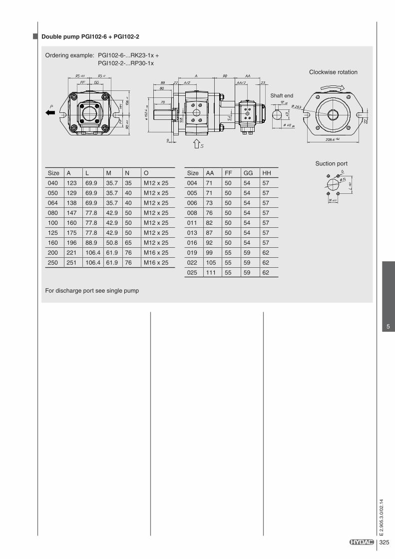
Size A F G H L M N O
004 71 50 54 57 38.1 17.5 14 M8 x 15
005 71 50 54 57 38.1 17.5 14 M8 x 15
006 73 50 54 57 47.5 22.0 19 M10 x 16
008 76 50 54 57 47.5 22.0 19 M10 x 16
011 82 50 54 57 52.4 26.2 25 M10 x 17
013 87 50 54 57 52.4 26.2 25 M10 x 17
016 92 50 54 57 52.4 26.2 25 M10 x 17
019 99 55 59 62 52.4 26.2 25 M10 x 17
022 105 55 59 62 52.4 26.2 25 M10 x 17
025 111 55 59 62 52.4 26.2 25 M10 x 17

322
E 2
.905
.3.0
/02.
14
Clockwise rotation
Shaft end
Size A F G H
004 71 50 54 57
005 71 50 54 57
006 73 50 54 57
008 76 50 54 57
011 82 50 54 57
013 87 50 54 57
016 92 50 54 57
019 99 55 59 62
022 105 55 59 62
025 111 55 59 62
For discharge port see single pump
5.3.13 PGI102-6
Ordering example: PGI102-6-...RK23-1x
5.3.14 Double pump PGI102-2 + PGI102-2 Ordering example: PGI102-2-...RK00-1x+ PGI102-2-...RP30-1x
Suction port NG 004-016
Suction port NG 019-025
Clockwise rotation
Suction port
Shaft end
Size A B C D E L M N O
040 123 57.2* 27.8* M12 x 22 20 69.9 35.7 35 M12 x 25
050 129 57.2* 27.8* M12 x 22 20 69.9 35.7 40 M12 x 25
064 138 57.2* 27.8* M12 x 22 20 69.9 35.7 40 M12 x 25
080 147 66.7* 31.8* M14 x 25 30 77.8 42.9 50 M12 x 25
100 160 66.7* 31.8* M14 x 25 30 77.8 42.9 50 M12 x 25
125 175 66.7* 31.8* M14 x 25 30 77.8 42.9 50 M12 x 25
160 196 66.7* 31.8* M14 x 25 30 88.9 50.8 65 M12 x 25
200 221 79.4* 36.5* M16 x 28 38 106.4 61.9 76 M16 x 25
250 251 79.4* 36.5* M16 x 28 38 106.4 61.9 76 M16 x 25
* Discharge port: SAE 518C, High pressure range (code 62)
323
E 2
.905
.3.0
/02.
14
5
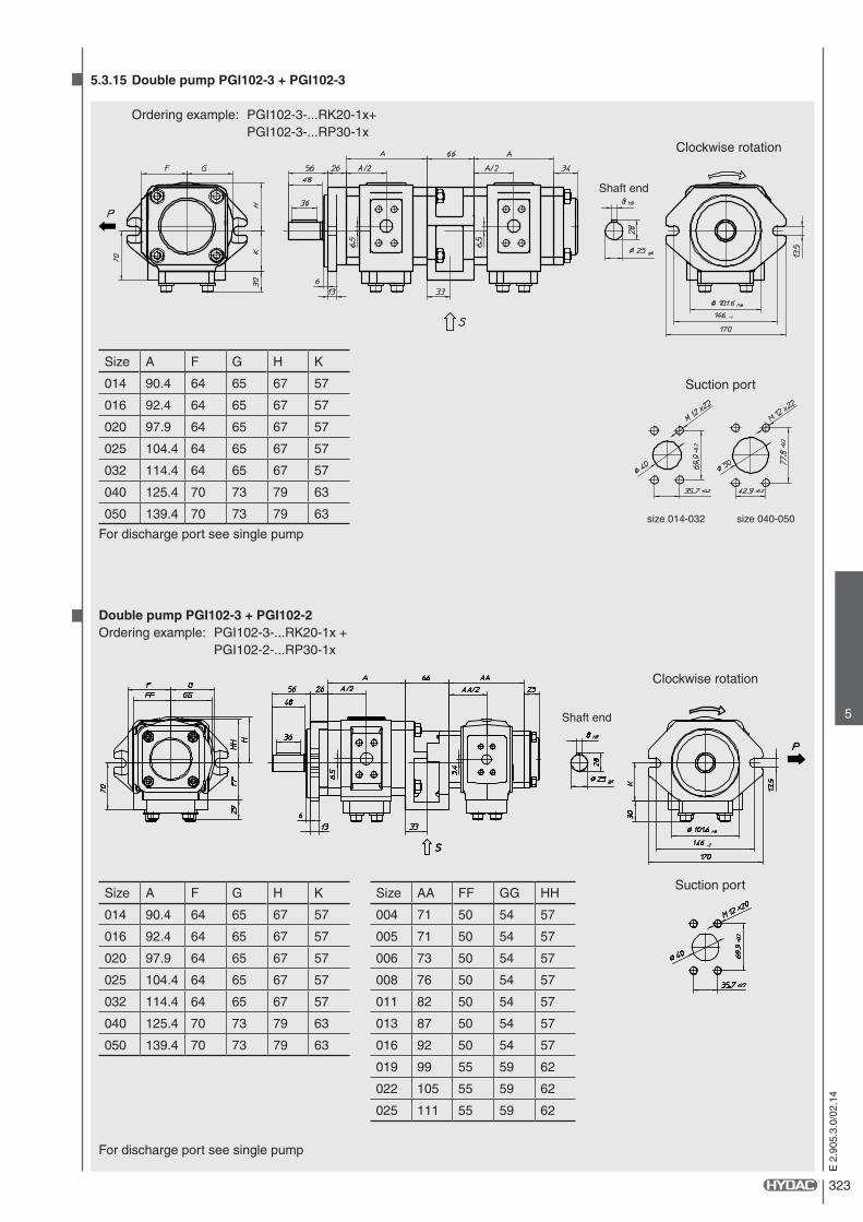
Double pump PGI102-3 + PGI102-2Ordering example: PGI102-3-...RK20-1x + PGI102-2-...RP30-1x
Size A F G H K
014 90.4 64 65 67 57
016 92.4 64 65 67 57
020 97.9 64 65 67 57
025 104.4 64 65 67 57
032 114.4 64 65 67 57
040 125.4 70 73 79 63
050 139.4 70 73 79 63
For discharge port see single pump
5.3.15 Double pump PGI102-3 + PGI102-3
Ordering example: PGI102-3-...RK20-1x+ PGI102-3-...RP30-1x
Suction port
Suction port
size 014-032 size 040-050
Clockwise rotation
Clockwise rotation
Shaft end
Shaft end
Size A F G H K Size AA FF GG HH
014 90.4 64 65 67 57 004 71 50 54 57
016 92.4 64 65 67 57 005 71 50 54 57
020 97.9 64 65 67 57 006 73 50 54 57
025 104.4 64 65 67 57 008 76 50 54 57
032 114.4 64 65 67 57 011 82 50 54 57
040 125.4 70 73 79 63 013 87 50 54 57
050 139.4 70 73 79 63 016 92 50 54 57
019 99 55 59 62
022 105 55 59 62
025 111 55 59 62
For discharge port see single pump

324
E 2
.905
.3.0
/02.
14
Clockwise rotation
Clockwise rotation
Suction port
Suction port
Shaft end
Shaft end
Size A
040 123
050 129
064 138
080 147
100 160
125 175
160 196
200 221
250 251
For discharge port see single pump
Double pump PGI102-6 + PGI102-3Ordering example: PGI102-6-...RK20-1x + PGI102-3-...RP30-1x
Size A Size AA FF GG HH KK
040 123 014 90.4 64 65 67 57
050 129 016 92.4 64 65 67 57
064 138 020 97.9 64 65 67 57
080 147 025 104.4 64 65 67 57
100 160 032 114.4 64 65 67 57
125 175 040 125.4 70 73 79 63
160 196 050 139.4 70 73 79 63
200 221
250 251
For discharge port see single pump
5.3.16 Double pump PGI102-6 + PGI102-6
Ordering example: PGI102-6-...RK20-1x+ PGI102-6-...RP30-1x
325
E 2
.905
.3.0
/02.
14
5
Clockwise rotation
Suction port
Shaft end
Size A L M N O Size AA FF GG HH
040 123 69.9 35.7 35 M12 x 25 004 71 50 54 57
050 129 69.9 35.7 40 M12 x 25 005 71 50 54 57
064 138 69.9 35.7 40 M12 x 25 006 73 50 54 57
080 147 77.8 42.9 50 M12 x 25 008 76 50 54 57
100 160 77.8 42.9 50 M12 x 25 011 82 50 54 57
125 175 77.8 42.9 50 M12 x 25 013 87 50 54 57
160 196 88.9 50.8 65 M12 x 25 016 92 50 54 57
200 221 106.4 61.9 76 M16 x 25 019 99 55 59 62
250 251 106.4 61.9 76 M16 x 25 022 105 55 59 62
025 111 55 59 62
For discharge port see single pump
Double pump PGI102-6 + PGI102-2
Ordering example: PGI102-6-...RK23-1x + PGI102-2-...RP30-1x

326
E 2
.905
.3.0
/02.
14
Related Documents