Journal of Mechanical Engineering and Sciences ISSN (Print): 2289-4659; e-ISSN: 2231-8380 Volume 13, Issue 3, pp. 5212-5227, September 2019 © Universiti Malaysia Pahang, Malaysia DOI: https://doi.org/10.15282/jmes.13.3.2019.01.0427 5212 A new type of magnetic pump with coupled mechanical vibration and electromagnetic force Hiroyuki Yaguchi 1* , Toshiki Mishina 1 and Kazumi Ishikawa 1 1 Faculty of Mechanical Engineering, Tohoku Gakuin University, 1-13-1 Chuo, Tagajo, Miyagi, Japan * Email: [email protected] Phone: +81 22368710; Fax: +81 223687070 ABSTRACT There is a demand for intravenous drips for medical sites and for liquid delivery of microfluidic chips in the field of chemical analysis. Furthermore, in these chemical analysis and medical pumps, disposable is often required. In this paper, a new pump capable of disposable having a size of 19 mm in outer diameter and 56 mm in length combining electromagnetic force and mechanical vibration was proposed. In the experiment, optimization of casing and discharge valve of this pump was examined and tested. Next, by attaching an iron plate to the iron core of the electromagnet, a method of increasing the strength of the magnetic field at one pole of the electromagnet without changing the magnetic circuit of the pump was suggested. Due to optimized design and utilization of asymmetric magnetic field, the maximum efficiency of the pump was 10.7 %. Furthermore, it was shown that this pump can deliver water to the pumping head exceeding 1000 mm. Keywords: magnetic pump; vibration; pumping head; efficiency; mass flow; asymmetric magnetic field. INTRODUCTION Pumps with high power and efficiency are highly demanded in various industrial fields and numerous researches have been conducted. Among them, for axial flow pumps [1], centrifugal pumps [2-4], mixed-flow pump [5-6], positive displacement pumps [7-8] and rotary pumps [9-12], the operating principle of these preexisting pumps is almost completely established. Improvements in the output and efficiency characteristics of these pumps depend on the built-in electromagnetic motors. By development of the electromagnetic motor with high efficiency in recent years, the centrifugal pump having the efficiency of about 90 % have been studied [13-14]. On the other hand, there is a demand for intravenous drips at medical sites and for liquid delivery of microfluidic chips in the field of chemical analysis. Furthermore, in these chemical analysis and medical pumps, disposable is often required. Based on the above considerations, many studies with regard to a new type of the pump have investigated. Previously proposed typical methods include the following: electromagnet [15-16], solenoid [17] electrostatic[18], piezoelectric [19-22], super magnetostriction [23-26], type using external magnetic field [27-29], type using elasticity of shape memory alloy [30-31], and

Welcome message from author
This document is posted to help you gain knowledge. Please leave a comment to let me know what you think about it! Share it to your friends and learn new things together.
Transcript
Journal of Mechanical Engineering and Sciences
ISSN (Print): 2289-4659; e-ISSN: 2231-8380
Volume 13, Issue 3, pp. 5212-5227, September 2019
© Universiti Malaysia Pahang, Malaysia
DOI: https://doi.org/10.15282/jmes.13.3.2019.01.0427
5212
A new type of magnetic pump with coupled mechanical vibration and electromagnetic
force
Hiroyuki Yaguchi1*, Toshiki Mishina1 and Kazumi Ishikawa1
1Faculty of Mechanical Engineering, Tohoku Gakuin University,
1-13-1 Chuo, Tagajo, Miyagi, Japan *Email: [email protected]
Phone: +81 22368710; Fax: +81 223687070
ABSTRACT
There is a demand for intravenous drips for medical sites and for liquid delivery of
microfluidic chips in the field of chemical analysis. Furthermore, in these chemical analysis
and medical pumps, disposable is often required. In this paper, a new pump capable of
disposable having a size of 19 mm in outer diameter and 56 mm in length combining
electromagnetic force and mechanical vibration was proposed. In the experiment,
optimization of casing and discharge valve of this pump was examined and tested. Next, by
attaching an iron plate to the iron core of the electromagnet, a method of increasing the
strength of the magnetic field at one pole of the electromagnet without changing the magnetic
circuit of the pump was suggested. Due to optimized design and utilization of asymmetric
magnetic field, the maximum efficiency of the pump was 10.7 %. Furthermore, it was shown
that this pump can deliver water to the pumping head exceeding 1000 mm.
Keywords: magnetic pump; vibration; pumping head; efficiency; mass flow; asymmetric
magnetic field.
INTRODUCTION
Pumps with high power and efficiency are highly demanded in various industrial fields and
numerous researches have been conducted. Among them, for axial flow pumps [1],
centrifugal pumps [2-4], mixed-flow pump [5-6], positive displacement pumps [7-8] and
rotary pumps [9-12], the operating principle of these preexisting pumps is almost completely
established. Improvements in the output and efficiency characteristics of these pumps depend
on the built-in electromagnetic motors. By development of the electromagnetic motor with
high efficiency in recent years, the centrifugal pump having the efficiency of about 90 %
have been studied [13-14].
On the other hand, there is a demand for intravenous drips at medical sites and for
liquid delivery of microfluidic chips in the field of chemical analysis. Furthermore, in these
chemical analysis and medical pumps, disposable is often required. Based on the above
considerations, many studies with regard to a new type of the pump have investigated.
Previously proposed typical methods include the following: electromagnet [15-16], solenoid
[17] electrostatic[18], piezoelectric [19-22], super magnetostriction [23-26], type using
external magnetic field [27-29], type using elasticity of shape memory alloy [30-31], and
Hiroyuki et. al / Journal of Mechanical Engineering and Sciences 13(3) 2019 5212-5227
5213
type using electro-hydrodynamic [32]. For the above-mentioned new type pumps, the flow
rate characteristics have been elucidated in detail. However, its efficiency has not been
clarified. No pumps with efficiencies exceeding 10 % are found in these studies. Furthermore,
the pump having a size of about 20 mm in outer diameter and 50 mm in length and capable
of disposable has not yet been developed. Considering recent high performance of permanent
magnets, development of a new pump of electromagnetic-mechanical vibration type is an
important problem.
In this paper, a new small size pump combining electromagnetic force and mechanical
vibration was proposed. The small size pump of vibration type with an outer diameter of 19
mm and a height of 56 mm was prototyped, and the optimum design of the pump shape was
carried out. This pump demonstrated a maximum efficiency of 6.0 % with a pumping head
of 200 mm. By attaching an iron plate to the iron core of an electromagnet, a method of
increasing the strength of the magnetic field at one pole of the electromagnet without
changing the magnetic circuit was suggested. By the generation of an asymmetric magnetic
field due to the addition of the iron material, the maximum efficiency of the pump was
10.7 %. In addition, this small size pump has a very simple structure and can deliver water
to the pumping head exceeding 1000 mm.
STRUCTURE OF MAGNETIC PUMP
Figure 1 shows a diagram of the magnetic pump prototyped for liquid delivery of various
fluids. This pump is divided into a head part and a propulsion part. The head part is made of
an acrylic material having an outer diameter of 19 mm, an inner diameter of 15 mm and a
height of 18 mm. This head part has a discharge port with an outer diameter of 6 mm. In the
propulsion part, a vibration component is inserted in an acrylic pipe having an outer diameter
of 19 mm and an inner diameter of 15 mm, a height of 37 mm and a discharge valve is attached
to the upper part. The propulsion part has a suction port with an outer diameter of 6 mm at a
position 9 mm from the bottom. Thus, the magnetic pump consists of a permanent magnet and
a translational spring constituting the vibration component, the discharge valve and the acrylic
casing with a support base. The permanent magnet is cylindrical NdFeB and is magnetized in
the axial direction. The permanent magnet was 12 mm in diameter and 5 mm in height. The
surface magnetic flux density measured using a tesla meter was 358 mT. The translational
spring was a stainless steel compression coil type having an outer diameter of 12 mm, a free
length of 25 mm, and a spring constant k of 2,691 N/m.
The vibration component was constructed of the translational spring and the
permanent magnet. An electromagnet was inserted in the translational spring. The
electromagnet consists of an iron core having a diameter of 3.4 mm and a length of 21 mm
with 1130 turns of 0.12-mm-diameter copper wire. The electrical resistance of the
electromagnet is 12.4 Ω. The gap between the electromagnet and the permanent magnet in the
static condition is 3 mm.
A new type of magnetic pump with coupled mechanical vibration and electromagnetic force
5214
19 mm
56 m
m
36 m
m18
mm
1 m
mΦ
NS
Suction
Valve
DischargeHead
part
Bottom
part
Acrylic
casing
15 mmΦ
NS
Electro-
magnet
Permanent
magnet
Support base
Spring
Vibration
(a) Outline (Cross section) (b) Vibration component
Figure 1. Structure of magnetic pump.
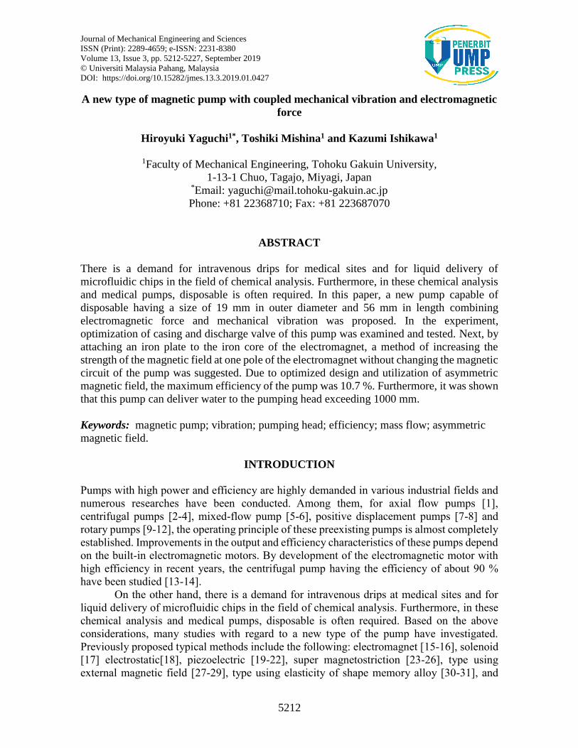
Figure 2. Detail of valve part.
h m
m d mm
1 mm 1.5 mm 2 m
m
6.5 mm
Acrylic plate
Triangular acrylic support
10.5 mm
8 m
m
Hole
Silicon Rubber
Φ
Hiroyuki et. al / Journal of Mechanical Engineering and Sciences 13(3) 2019 5212-5227
5215
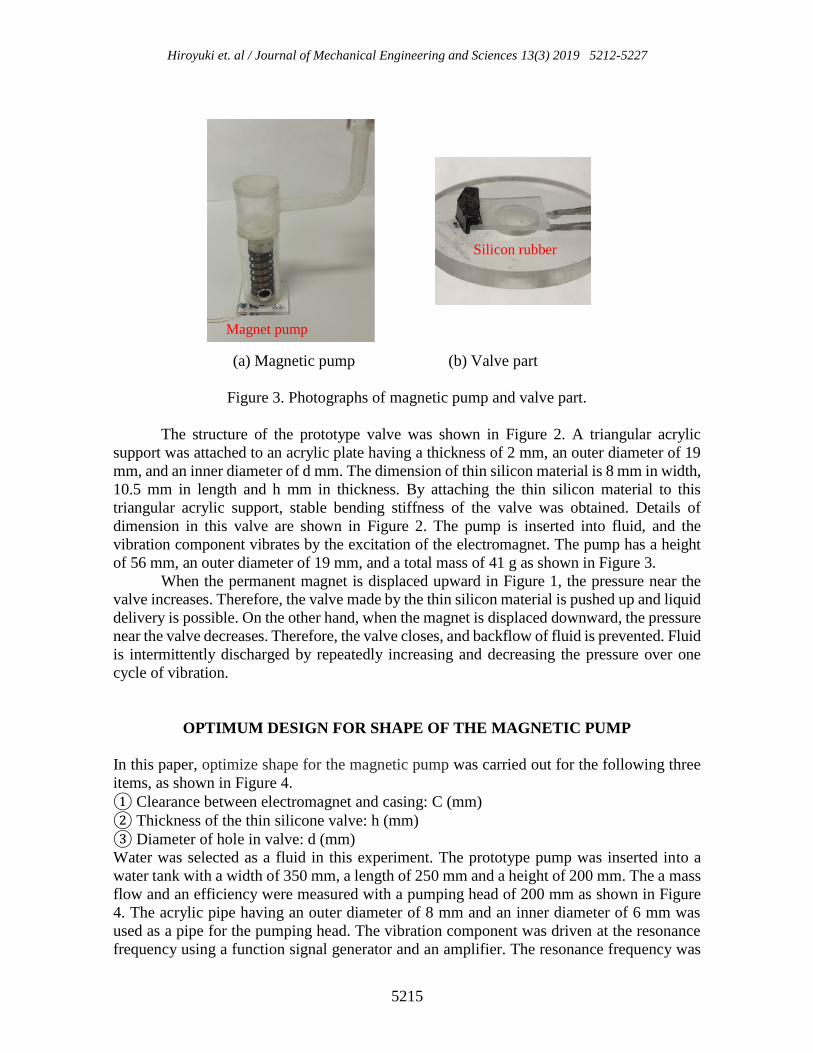
(a) Magnetic pump (b) Valve part
Figure 3. Photographs of magnetic pump and valve part.
The structure of the prototype valve was shown in Figure 2. A triangular acrylic
support was attached to an acrylic plate having a thickness of 2 mm, an outer diameter of 19
mm, and an inner diameter of d mm. The dimension of thin silicon material is 8 mm in width,
10.5 mm in length and h mm in thickness. By attaching the thin silicon material to this
triangular acrylic support, stable bending stiffness of the valve was obtained. Details of
dimension in this valve are shown in Figure 2. The pump is inserted into fluid, and the
vibration component vibrates by the excitation of the electromagnet. The pump has a height
of 56 mm, an outer diameter of 19 mm, and a total mass of 41 g as shown in Figure 3.
When the permanent magnet is displaced upward in Figure 1, the pressure near the
valve increases. Therefore, the valve made by the thin silicon material is pushed up and liquid
delivery is possible. On the other hand, when the magnet is displaced downward, the pressure
near the valve decreases. Therefore, the valve closes, and backflow of fluid is prevented. Fluid
is intermittently discharged by repeatedly increasing and decreasing the pressure over one
cycle of vibration.
OPTIMUM DESIGN FOR SHAPE OF THE MAGNETIC PUMP
In this paper, optimize shape for the magnetic pump was carried out for the following three
items, as shown in Figure 4.
① Clearance between electromagnet and casing: C (mm)
② Thickness of the thin silicone valve: h (mm)
③ Diameter of hole in valve: d (mm)
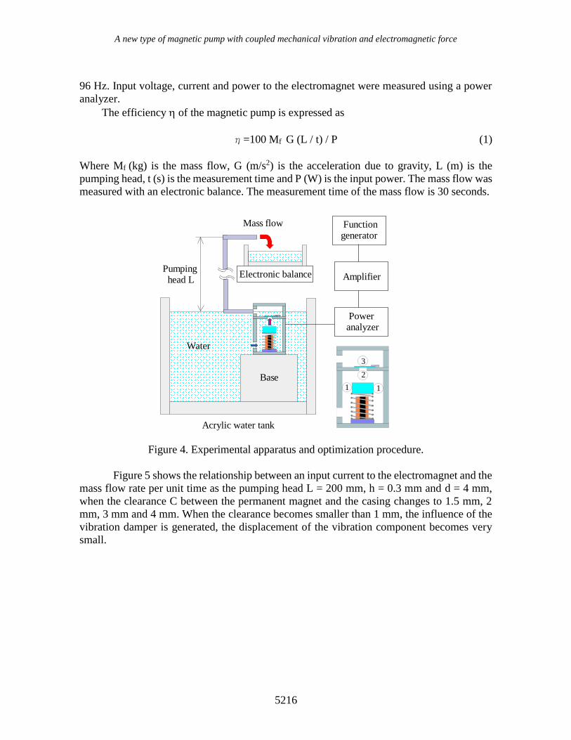
Water was selected as a fluid in this experiment. The prototype pump was inserted into a
water tank with a width of 350 mm, a length of 250 mm and a height of 200 mm. The a mass
flow and an efficiency were measured with a pumping head of 200 mm as shown in Figure
4. The acrylic pipe having an outer diameter of 8 mm and an inner diameter of 6 mm was
used as a pipe for the pumping head. The vibration component was driven at the resonance
frequency using a function signal generator and an amplifier. The resonance frequency was
Silicon rubber
Magnet pump
A new type of magnetic pump with coupled mechanical vibration and electromagnetic force
5216
96 Hz. Input voltage, current and power to the electromagnet were measured using a power
analyzer.
The efficiency of the magnetic pump is expressed as
η=100 Mf G (L / t) / P (1)
Where Mf (kg) is the mass flow, G (m/s2) is the acceleration due to gravity, L (m) is the
pumping head, t (s) is the measurement time and P (W) is the input power. The mass flow was
measured with an electronic balance. The measurement time of the mass flow is 30 seconds.
Figure 4. Experimental apparatus and optimization procedure.
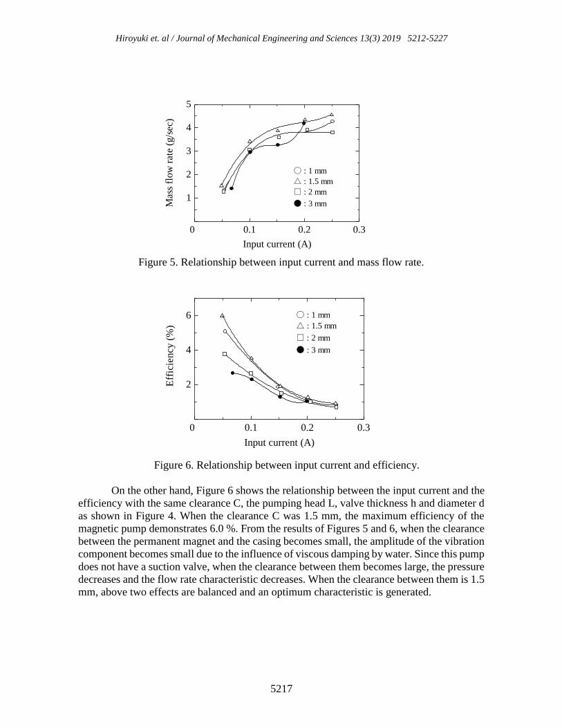
Figure 5 shows the relationship between an input current to the electromagnet and the
mass flow rate per unit time as the pumping head L = 200 mm, h = 0.3 mm and d = 4 mm,
when the clearance C between the permanent magnet and the casing changes to 1.5 mm, 2
mm, 3 mm and 4 mm. When the clearance becomes smaller than 1 mm, the influence of the
vibration damper is generated, the displacement of the vibration component becomes very
small.
Acrylic water tank
Electronic balance
Mass flow
Water
Pumping head L
Base
Functiongenerator
Amplifier
Poweranalyzer
1 1
2
3
Hiroyuki et. al / Journal of Mechanical Engineering and Sciences 13(3) 2019 5212-5227
5217
Figure 5. Relationship between input current and mass flow rate.
Figure 6. Relationship between input current and efficiency.
On the other hand, Figure 6 shows the relationship between the input current and the
efficiency with the same clearance C, the pumping head L, valve thickness h and diameter d
as shown in Figure 4. When the clearance C was 1.5 mm, the maximum efficiency of the
magnetic pump demonstrates 6.0 %. From the results of Figures 5 and 6, when the clearance
between the permanent magnet and the casing becomes small, the amplitude of the vibration
component becomes small due to the influence of viscous damping by water. Since this pump
does not have a suction valve, when the clearance between them becomes large, the pressure
decreases and the flow rate characteristic decreases. When the clearance between them is 1.5
mm, above two effects are balanced and an optimum characteristic is generated.
0.1 0.2 0.3
1
2
3
4
5
0
Input current (A)
Mas
s fl
ow
rat
e (g
/sec
)
● : 3 mm
〇 : 1 mm
△ : 1.5 mm
□ : 2 mm
0.1 0.2 0.3
2
4
6
0
Input current (A)
Eff
icie
ncy
(%
)
〇 : 1 mm
△ : 1.5 mm
□ : 2 mm
● : 3 mm
A new type of magnetic pump with coupled mechanical vibration and electromagnetic force
5218
Figure 7. Relationship between input current and mass flow rate.
Figure 8. Relationship between input current and efficiency.
Figure 9. Relationship between input current and mass flow rate.
0.1 0.2 0.3
2
4
6
8
0
Input current (A)
Mass
flo
w r
ate
(g/s
ec)
〇 : 4 mm, 0.3 mm
△ : 4 mm, 0.5 mm
□ : 6 mm, 0.3 mm
▽ : 6 mm, 0.5 mm
× : 8 mm, 0.3 mm+ : 8 mm, 0.5 mm
0.1 0.2 0.3
2
4
6
0
Input current (A)
Eff
icie
ncy
(%
)
〇 : 4 mm, 0.3 mm
△ : 4 mm, 0.5 mm
□ : 6 mm, 0.3 mm
▽ : 6 mm, 0.5 mm
× : 8 mm, 0.3 mm
+ : 8 mm, 0.5 mm
0.1 0.2 0.3
1
2
3
4
0
Input current (A)
Mass
flo
w r
ate
(g/s
ec)
〇 : 0.1 mm △ : 0.2 mm
□ : 0.3 mm × : 0.5 mm
Hiroyuki et. al / Journal of Mechanical Engineering and Sciences 13(3) 2019 5212-5227
5219
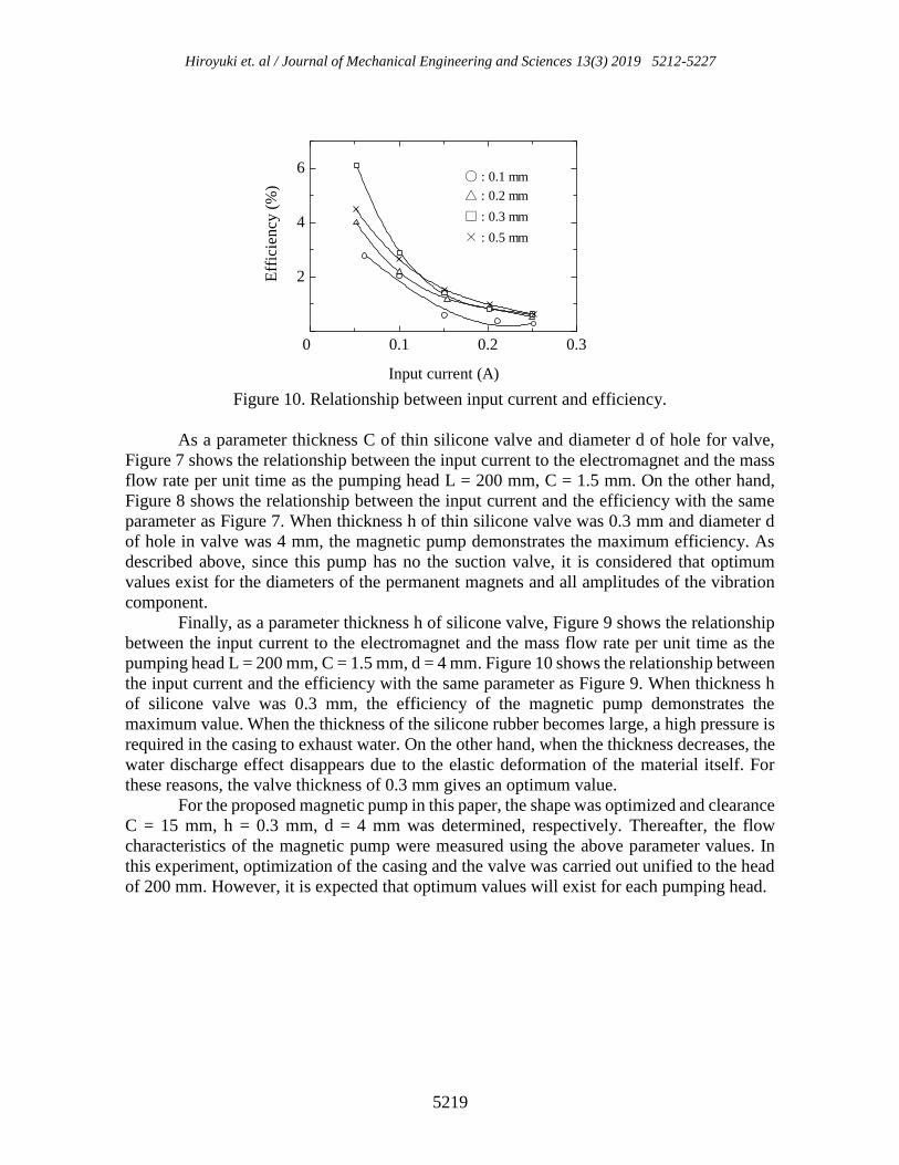
Figure 10. Relationship between input current and efficiency.
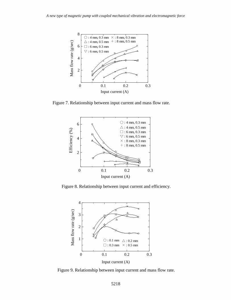
As a parameter thickness C of thin silicone valve and diameter d of hole for valve,
Figure 7 shows the relationship between the input current to the electromagnet and the mass
flow rate per unit time as the pumping head L = 200 mm, C = 1.5 mm. On the other hand,
Figure 8 shows the relationship between the input current and the efficiency with the same
parameter as Figure 7. When thickness h of thin silicone valve was 0.3 mm and diameter d
of hole in valve was 4 mm, the magnetic pump demonstrates the maximum efficiency. As
described above, since this pump has no the suction valve, it is considered that optimum
values exist for the diameters of the permanent magnets and all amplitudes of the vibration
component.
Finally, as a parameter thickness h of silicone valve, Figure 9 shows the relationship
between the input current to the electromagnet and the mass flow rate per unit time as the
pumping head L = 200 mm, C = 1.5 mm, d = 4 mm. Figure 10 shows the relationship between
the input current and the efficiency with the same parameter as Figure 9. When thickness h
of silicone valve was 0.3 mm, the efficiency of the magnetic pump demonstrates the
maximum value. When the thickness of the silicone rubber becomes large, a high pressure is
required in the casing to exhaust water. On the other hand, when the thickness decreases, the
water discharge effect disappears due to the elastic deformation of the material itself. For
these reasons, the valve thickness of 0.3 mm gives an optimum value. For the proposed magnetic pump in this paper, the shape was optimized and clearance
C = 15 mm, h = 0.3 mm, d = 4 mm was determined, respectively. Thereafter, the flow
characteristics of the magnetic pump were measured using the above parameter values. In
this experiment, optimization of the casing and the valve was carried out unified to the head
of 200 mm. However, it is expected that optimum values will exist for each pumping head.
0.1 0.2 0.3
2
4
6
0
Input current (A)
Eff
icie
ncy
(%
)
〇 : 0.1 mm
△ : 0.2 mm
□ : 0.3 mm
× : 0.5 mm
A new type of magnetic pump with coupled mechanical vibration and electromagnetic force
5220
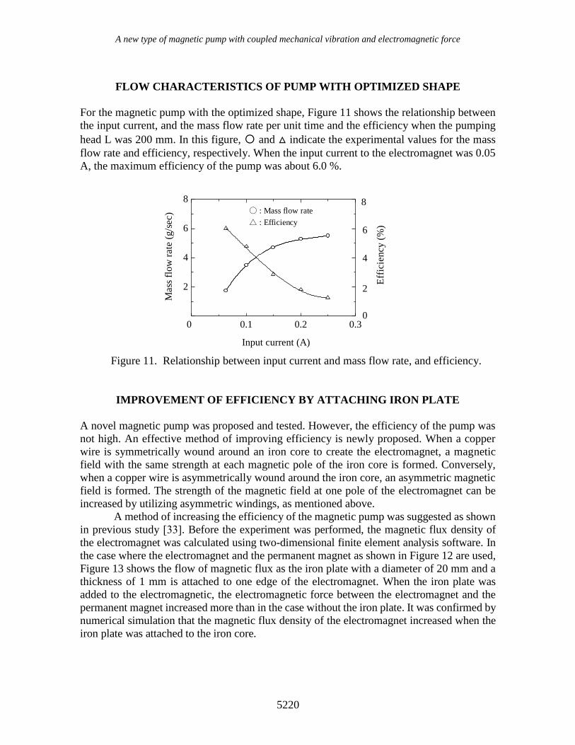
FLOW CHARACTERISTICS OF PUMP WITH OPTIMIZED SHAPE
For the magnetic pump with the optimized shape, Figure 11 shows the relationship between
the input current, and the mass flow rate per unit time and the efficiency when the pumping
head L was 200 mm. In this figure, 〇 and △ indicate the experimental values for the mass
flow rate and efficiency, respectively. When the input current to the electromagnet was 0.05
A, the maximum efficiency of the pump was about 6.0 %.
Figure 11. Relationship between input current and mass flow rate, and efficiency.
IMPROVEMENT OF EFFICIENCY BY ATTACHING IRON PLATE
A novel magnetic pump was proposed and tested. However, the efficiency of the pump was
not high. An effective method of improving efficiency is newly proposed. When a copper
wire is symmetrically wound around an iron core to create the electromagnet, a magnetic
field with the same strength at each magnetic pole of the iron core is formed. Conversely,
when a copper wire is asymmetrically wound around the iron core, an asymmetric magnetic
field is formed. The strength of the magnetic field at one pole of the electromagnet can be
increased by utilizing asymmetric windings, as mentioned above.
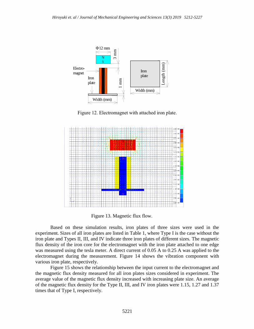
A method of increasing the efficiency of the magnetic pump was suggested as shown
in previous study [33]. Before the experiment was performed, the magnetic flux density of
the electromagnet was calculated using two-dimensional finite element analysis software. In
the case where the electromagnet and the permanent magnet as shown in Figure 12 are used,
Figure 13 shows the flow of magnetic flux as the iron plate with a diameter of 20 mm and a
thickness of 1 mm is attached to one edge of the electromagnet. When the iron plate was
added to the electromagnetic, the electromagnetic force between the electromagnet and the
permanent magnet increased more than in the case without the iron plate. It was confirmed by
numerical simulation that the magnetic flux density of the electromagnet increased when the
iron plate was attached to the iron core.
0.1 0.2 0.3
2
4
6
8
0
8
6
4
2
0
Input current (A)
Mass
flo
w r
ate
(g
/sec) 〇 : Mass flow rate
△ : Efficiency
Eff
icie
ncy
(%
)
Hiroyuki et. al / Journal of Mechanical Engineering and Sciences 13(3) 2019 5212-5227
5221
Figure 12. Electromagnet with attached iron plate.
Figure 13. Magnetic flux flow.
Based on these simulation results, iron plates of three sizes were used in the
experiment. Sizes of all iron plates are listed in Table 1, where Type I is the case without the
iron plate and Types II, III, and IV indicate three iron plates of different sizes. The magnetic
flux density of the iron core for the electromagnet with the iron plate attached to one edge
was measured using the tesla meter. A direct current of 0.05 A to 0.25 A was applied to the
electromagnet during the measurement. Figure 14 shows the vibration component with
various iron plate, respectively.
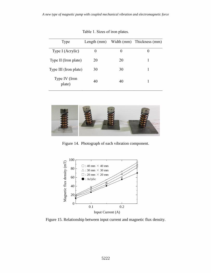
Figure 15 shows the relationship between the input current to the electromagnet and
the magnetic flux density measured for all iron plates sizes considered in experiment. The
average value of the magnetic flux density increased with increasing plate size. An average
of the magnetic flux density for the Type II, III, and IV iron plates were 1.15, 1.27 and 1.37
times that of Type I, respectively.
12 mm
Ironplate
Electro-magnet
3 m
m
1 m
m
Width (mm)
Width (mm)
Len
gth
(m
m)
NS
Iron plate
Φ
A new type of magnetic pump with coupled mechanical vibration and electromagnetic force
5222
Table 1. Sizes of iron plates.
Type Length (mm) Width (mm) Thickness (mm)
Type I (Acrylic) 0 0 0
Type II (Iron plate) 20 20 1
Type III (Iron plate) 30 30 1
Type IV (Iron
plate) 40 40 1
Figure 14. Photograph of each vibration component.
Figure 15. Relationship between input current and magnetic flux density.
0.1 0.20
20
40
60
80
100
Input Current (A)
Magneti
c f
lux d
ensi
ty (
mT
)
〇 : 40 mm × 40 mm
△ : 30 mm × 30 mm
□ : 20 mm × 20 mm
● : Aclylic
Hiroyuki et. al / Journal of Mechanical Engineering and Sciences 13(3) 2019 5212-5227
5223
Figure 16. Relationship between input current and efficiency.
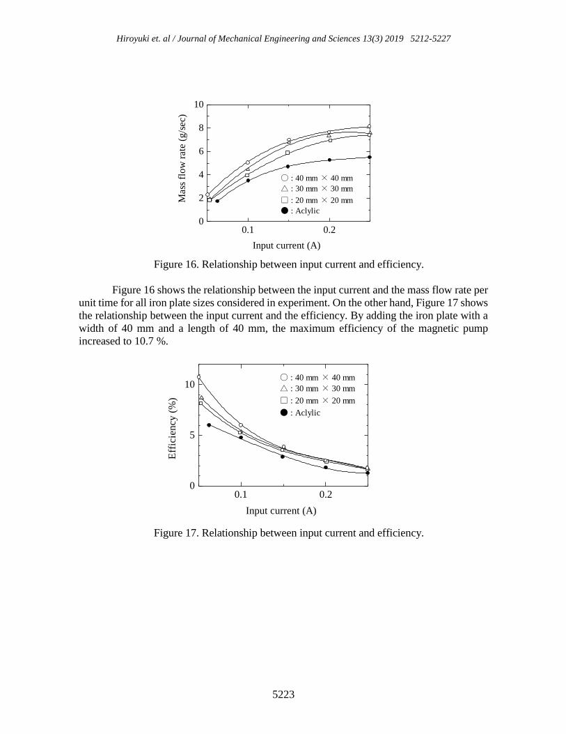
Figure 16 shows the relationship between the input current and the mass flow rate per
unit time for all iron plate sizes considered in experiment. On the other hand, Figure 17 shows
the relationship between the input current and the efficiency. By adding the iron plate with a
width of 40 mm and a length of 40 mm, the maximum efficiency of the magnetic pump
increased to 10.7 %.
Figure 17. Relationship between input current and efficiency.
0.1 0.20
2
4
6
8
10
Mass
flo
w r
ate
(g
/sec)
Input current (A)
〇 : 40 mm × 40 mm
△ : 30 mm × 30 mm
□ : 20 mm × 20 mm
● : Aclylic
0.1 0.20
5
10
Eff
icie
ncy
(%
)
Input current (A)
〇 : 40 mm × 40 mm
△ : 30 mm × 30 mm
□ : 20 mm × 20 mm
● : Aclylic
A new type of magnetic pump with coupled mechanical vibration and electromagnetic force
5224
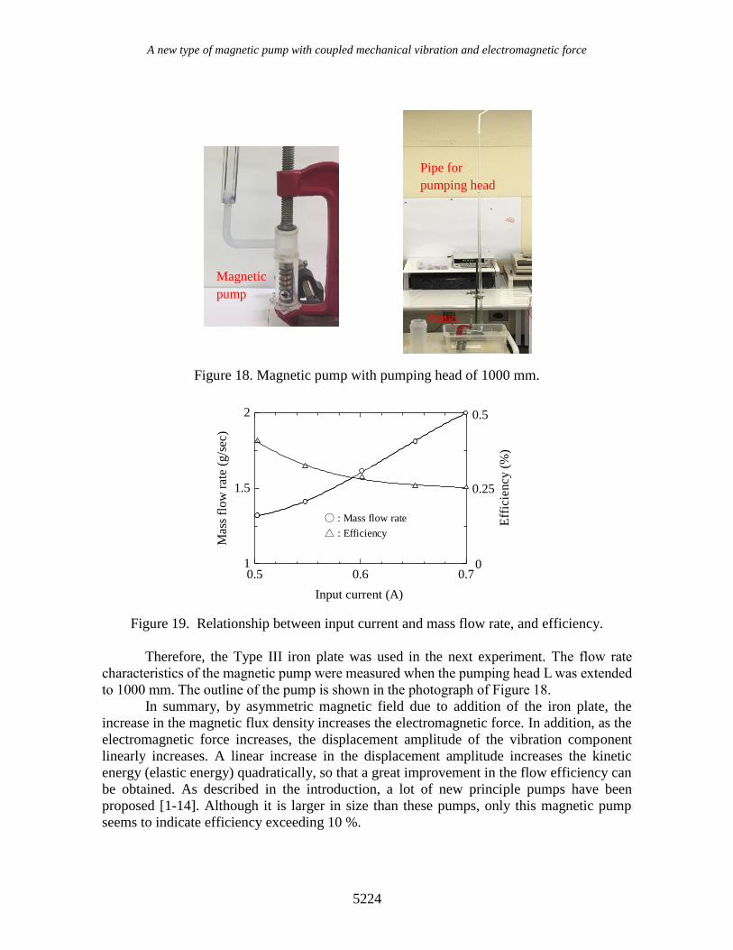
Figure 18. Magnetic pump with pumping head of 1000 mm.
Figure 19. Relationship between input current and mass flow rate, and efficiency.
Therefore, the Type III iron plate was used in the next experiment. The flow rate
characteristics of the magnetic pump were measured when the pumping head L was extended
to 1000 mm. The outline of the pump is shown in the photograph of Figure 18.
In summary, by asymmetric magnetic field due to addition of the iron plate, the
increase in the magnetic flux density increases the electromagnetic force. In addition, as the
electromagnetic force increases, the displacement amplitude of the vibration component
linearly increases. A linear increase in the displacement amplitude increases the kinetic
energy (elastic energy) quadratically, so that a great improvement in the flow efficiency can
be obtained. As described in the introduction, a lot of new principle pumps have been
proposed [1-14]. Although it is larger in size than these pumps, only this magnetic pump
seems to indicate efficiency exceeding 10 %.
Magnetic
pump
Pipe for
pumping head
Pump
0.5 0.6 0.71
1.5
2
Mass
flo
w r
ate
(g
/sec)
Eff
icie
ncy
(%
)
Input current (A)
0.5
0.25
0
〇 : Mass flow rate
△ : Efficiency
Hiroyuki et. al / Journal of Mechanical Engineering and Sciences 13(3) 2019 5212-5227
5225
CONCLUSION
A novel magnetic pump combining electromagnetic force and mechanical vibration has been
proposed and the optimum design of the pump shape was carried out. The magnetic pump
with optimized shape demonstrated a maximum efficiency of 6.0 %.
On the other hand, based on the fact that an asymmetric electromagnet produces an
asymmetric magnetic field, a method of increasing the magnetic field strength at one pole of
the electromagnet by attaching an iron plate was proposed. By the generation of an
asymmetric magnetic field due to the addition of the iron material, the maximum efficiency
of the pump was 10.7 %. In addition, this small size pump has a very simple structure and
can deliver water to the pumping head exceeding 1000 mm.
REFERENCES
[1] Momosaki S, Usami S, Watanabe S, Furukawa A, Okuma K. Experimental Study on
Rotational Speed Control of Contra-Rotating Axial Flow Pump. Journal of TSJ.
2011;39:119-25.
[2] Yasuyuki N, Junichiro F. Effect of Impeller Outlet Width on Radial Thrust of Single-
Blade Centrifugal Pump with a Helical Spiral Suction Flow Channel. Journal of TSJ.
2011;39:47-56.
[3] Benra FK. Experimental Investigation of Hydrodynamic Forces for Different
Configurations of Single-Blade Centrifugal Pumps. The 11International Symposium
on Transport Phenomena and Dynamics of Rotating Machinery (ISROMAC-11).
2011;2011:24-30.
[4] Shigemitsu T, Fukutomi J, Takumi M, Masahiro S. Unsteady Flow Condition of
Centrifugal Pump for Low Viscous Fluid Food. International Journal of Fluid
Machinery and Systems. 2017;10:432-38.
[5] Nishi Y, Fukutomi J, Shigemitsu T, Higashide S. Improvement of Instability
Characteristics in a Mixed-Flow Pump Based on Flow near Blade Tip. The Japan
Society of Mechanical Engineers. 2011;77:1484-92.
[6] Day IJ. Active Suppression of Rotating Stall and Surge in Axial Compressors. ASME
Journal of Turbomachinery. 1993;115:40-7.
[7] Houzeaux G, Codina R. A finite element method for the solution of rotary pumps.
Comput. Fluids. 2007;36:667-79.
[8] Voorde JV, Vierendeels J, Dick E. Flow simulations in rotary volumetric pumps and
compressors with the fictitious domain method. Comput. Method Appl. Math.
2004;168:491-9.
[9] Kang YH, Vu HH. A newly developed rotor profile for lobe pumps. Journal of
Mechanical Science and Technology. 2014;28:915-26.
[10] Kang YH, Vu HH, Hsu CH. Factors impacting on performance of lobe pumps. A
numerical evaluation (J. Mech). 2012;28:229-38.
[11] Houzeaux G, Codina R. A finite element method for the solution of rotary pumps.
Comput. Fluids. 2007;36:667-79.
A new type of magnetic pump with coupled mechanical vibration and electromagnetic force
5226
[12] Voorde JV, Vierendeels J, Dick E. Flow simulations in rotary volumetric pumps and
compressors with the fictitious domain method. Comput. Method Appl. Math.
2004;168:491-9.
[13] Kurita H. Pump design for the next generation. Journal of the JIME. 2015;50:97-
100.
[14] Ohshima M. Efficiency Increase and Input Power Decrease of Converted Prototype
Pump Performance. Turbomachinery Society of Japan. 2011;39:712-21.
[15] Yin H, Huang H, Fang Y, Hsieh W. A novel electromagnetic elastomer membrane
actuator with a semi-embedded coil. Sensor and Actuator. 2007;139:194-202.
[16] Lee GH, Kim HR. Design analysis of DC electromagnetic pump for liquid sodium
CO2 reaction experimental characterization. Annals of Nuclear Energy.
2017;109:490-7.
[17] Guo S, Wang J, Guo J. A Novel Type of Micropump Using Solenoid Actuator for
Biomedical Applications. 2007 IEEE International Conference on Robotics and
Automation. 2007;2007:654-9.
[18] Ebrahim M. Design and simulation of a novel electrostatic peristaltic micromachined
pump for drug delivery applications. Sensor and Actuator. 2005;117:222-9.
[19] Kim J, Kang C, Kim Y. A disposable polydimethylsiloxane-based diffuser
micropump actuated by piezoelectric-disc. Microelectron Eng. 2004;71:119-124.
[20] Nguyen N, White RM. Design and optimization of an ultrasonic flexural plate wave
micropump using numerical simulation. Sensor and Actuator. 1999;77:229-36.
[21] Sateesh1 J, Rao K, Sravani1 K, Guha K, Kumar R. Design and Optimization of
MEMS Based Piezo-ElectroMicro Pump. 4th International Conference on
Microelectronics. 2017;2017:1200-6.
[22] Leng X, Zhang J, Zhao C. A spiral-tube-type valveless piezoelectric pump with
gyroscopic effect. Chinese Science Bulletin. 2014;59:1885-9.
[23] Claeyssen F, Lhermet N. Actuators Based on Giant Magnetostrictive Materials. 8th
International Conference on New Actuators. 2002;2002:10-2.
[24] Lu Q, Nie Q. Research on New Type of Giant Magnetostrictive PrecisionFlow Pump.
International Symposium on Material. Energy and Environment Engineering.
2005;2005:DOI: 10.2991/ism3e-15.
[25] Zhu Z, Liu F, Tao Z. A Novel Magnetostrictive Piston Pump and Its Working
Performance. IEEE International Conference on Applied System Innovation.
2018;2018:DOI: 10.1109/ICASI.2018.8394341.
[26] Quan L, Zhao Y, Nie Q. Design and Experiment of Rare Earth Giant Magnetostrictive
Piston Pump. Materials Science Forum. 2016;852:943-51.
[27] Kim SH, Hashi S, Ishiyama K. A Method for Acquiring the Torque of a Magnetic
Pump. IEEE Transaction on magnetics. 2011;47:3971-4.
[28] Kim SH, Yu CH, Ishiyama K. Tiny magnetic wireless pump: Fabrication of magnetic
impeller and magnetic wireless manipulation for blood circulation in legs. Journal of
Applied Physics. 2015;117:https://doi.org/10.1063/1.4916026.
[29] Song MK, Kim SH. Wireless Magnetic Pump, Characteristics of Magnetic Impellers
and Medical Application. Journal of Magnetics. 2017;22:344-51.
[30] Guo S, Asaka K. Polymer-based New Type of Micropump for Bio-medical
Application. Proceedings of 2003 IEEE International Conf. on Robotics and
Automation. 2003;2003:987-92.
Hiroyuki et. al / Journal of Mechanical Engineering and Sciences 13(3) 2019 5212-5227
5227
[31] Sagar SN, Sreekumar M. Miniaturized Flexible Flow Pump using SMA Actuator.
Procedia Engineering. 2013;64:896-906.
[32] Homsy A, Linder V, Lucklum F, Rooij NF. Magnetohydrodynamic pumping in
nuclear magnetic resonance environments. Sensor and Actuator. 2007;123:636-46.
[33] Yaguch H, Sakuma S. Vibration Actuator Capable of Movement on Magnetic
Substance Based on New Motion Principle. Journal of Vibroengineering.
2017;19:1494-1508.
Related Documents