Publication 520-IN009C-EN-P - July 2014 Installation Instructions PowerFlex 525 Incremental Encoder Input Catalog Number: 25-ENC-1 1 L1 L2 L3 O I 2 DC+ DC– 0V 0V Control Module Back Cover Incremental Encoder Input Wait three minutes after shutdown for capacitors to discharge to safe voltage levels. Voltage DIP switch 3 4 Mount the Incremental Encoder onto the Control Module Back Cover Lock the Incremental Encoder onto the Control Module Back Cover Mounting catch Locking tab Note: Incremental Encoder Input is for PowerFlex 525 only. You can install both the communication adapter and optional Incremental Encoder Input on the same Control Module Back Cover.

Welcome message from author
This document is posted to help you gain knowledge. Please leave a comment to let me know what you think about it! Share it to your friends and learn new things together.
Transcript
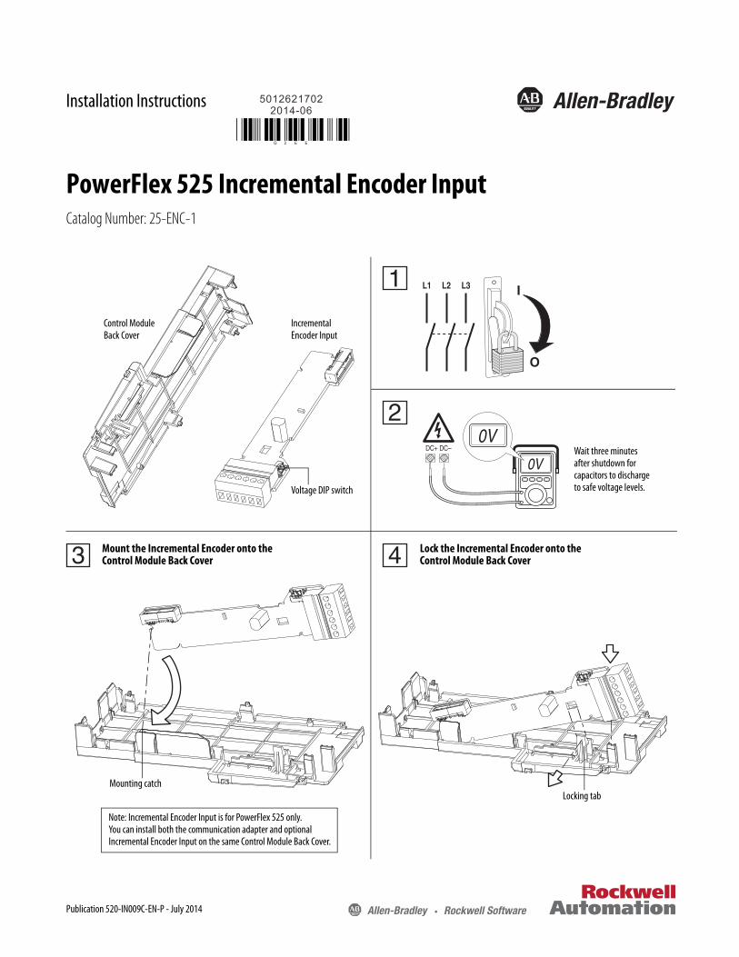
Installation Instructions
PowerFlex 525 Incremental Encoder InputCatalog Number: 25-ENC-1
1 L1 L2 L3
O
I
2DC+ DC–
0V
0V
Control Module Back Cover
Incremental Encoder Input
Wait three minutes after shutdown for capacitors to discharge to safe voltage levels.Voltage DIP switch
3 4Mount the Incremental Encoder onto theControl Module Back Cover
Lock the Incremental Encoder onto theControl Module Back Cover
Mounting catchLocking tab
Note: Incremental Encoder Input is for PowerFlex 525 only.You can install both the communication adapter and optional Incremental Encoder Input on the same Control Module Back Cover.
Publication 520-IN009C-EN-P - July 2014
PowerFlex 525 Incremental Encoder Input
+VCmB-BA-A12V 5V
�
5
6
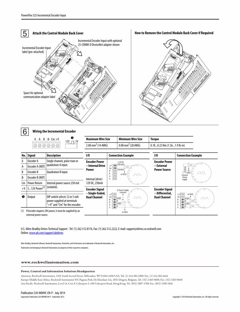
No. Signal Description
A Encoder A Single channel, pulse train or quadrature A input.A- Encoder A (NOT)
B Encoder B Quadrature B input.
B- Encoder B (NOT)
Cm Power Return Internal power source 250 mA (isolated).+V 5...12V Power(1)
(1) If Encoder requires 24V power, it must be supplied by an external power source.
Output DIP switch selects 12 or 5 volt power supplied at terminals “+V” and “Cm” for the encoder.
I/O Connection Example I/O Connection Example
Encoder Power– Internal Drive Power
Internal (drive) 12V DC, 250mA
Encoder Power– External Power Source
Encoder Signal– Single-Ended, Dual Channel
Encoder Signal – Differential, Dual Channel
Common
+12V DC(250 mA)
AA-BB-Cm+V
to SHLD
+ Comm
on
ExternalPowerSupply
toSHLD
A NOTA
BB NOT
to SHLD
to Power SupplyCommon
AA-BB-Cm+V to SHLD
A NOTB
A
B NOT
AA-BB-Cm+V
Wiring the Incremental Encoder
Attach the Control Module Back Cover How to Remove the Control Module Back Cover if Required
Maximum Wire Size Minimum Wire Size Torque
2.08 mm2 (14 AWG) 0.08 mm2 (28 AWG) 0.18...0.22 Nm (1.56...1.9 lb-in)
Incremental Encoder Input with optional 25-COMM-D DeviceNet adapter shown
Incremental Encoder Input label (pre-attached)
Space for optional communication adapter label
Publication 520-IN009C-EN-P - July 2014Supersedes Publication 520-IN009B-EN-P - September 2013 Copyright © 2014 Rockwell Automation, Inc. All rights reserved.
Allen-Bradley, Rockwell Software, Rockwell Automation, PowerFlex, and TechConnect are trademarks of Rockwell Automation, Inc.
Trademarks not belonging to Rockwell Automation are property of their respective companies.
U.S. Allen-Bradley Drives Technical Support - Tel: (1) 262.512.8176, Fax: (1) 262.512.2222, E-mail: [email protected]: www.ab.com/support/abdrives
Related Documents