
Welcome message from author
This document is posted to help you gain knowledge. Please leave a comment to let me know what you think about it! Share it to your friends and learn new things together.
Transcript

The Kid Charge ControllerInstruction Manual
MidNite Solar
1 7722 - 67th Ave NE
Arlington, Wa 98223
www.midnitesolar.com
Features● MPPT charge control ler gives maximum yield for solar, wind and hydro
● Standard model can wall or flush mount
● Marine model includes mounting bracket
● Backlit LCD display
● Works as a load control ler / Charge control ler
● Menu driven system control
● Can be input paral leled for a true 60 Amp single control ler
● Conformal coated circuit board for harsh environments

2 | Page 1 0-268-1 REV P1 0
The Kid Charge Controller Instructions
Preliminary
IMPORTANT SAFETY INSTRUCTIONSSAVE THESE INSTRUCTIONS - These instructions contain important safety and operatinginstructions for The Kid Charge Control ler.
I f you do not ful ly understand any of the concepts, terminology, or hazards outl ined in theseinstructions, please refer instal lation to a qualified dealer, electrician or instal ler. These instructionsare not meant to be a complete explanation of a renewable energy system.
GENERAL PRECAUTIONSWORKING WITH OR IN THE VICINITY OF A LEAD ACID BATTERY, SEALED OR VENTED ISDANGEROUS. VENTED BATTERIES GENERATE EXPLOSIVE GASES DURING NORMALOPERATION. FOR THIS REASON, IT IS VERY IMPORTANT THAT BEFORE SERVICINGEQUIPMENT IN THE VICINITY OF LEAD-ACID BATTERIES YOU REVIEW AND FOLLOW THESEINSTRUCTIONS CAREFULLY.
If service or repair should become necessary, contact MidNite Solar Inc. Improper servicing mayresult in a risk of shock, fire or explosion. To reduce these risks, disconnect al l wiring beforeattempting any maintenance or cleaning. Turning off the inverter wil l not reduce these risks. Solarmodules produce power when exposed to l ight. When it is not possible to disconnect the powercoming from the Photovoltaics by an external means such as a combiner, cover the modules with anopaque material before servicing any connected equipment.
Do not work alone. Someone should be in the range of your voice or close enough to come to youraid when you work with or near electrical equipment.
Remove rings, bracelets, necklaces, watches etc. when working with batteries, photovoltaic modulesor other electrical equipment. Power from an il luminated photovoltaic array makes a very effectivearc welder with dire consequences if one of the welded pieces is on your person.
To reduce the risk of injury, connect only deep cycle lead acid type rechargeable batteries. Othertypes of batteries may leak or burst, causing personal injury or damage.
This equipment is NOT intended for use with l ife support equipment or other medical equipment ordevices.
I t is the responsibi l ity of the instal ler to verify compliance with al l applicable codes.Before making any connections verify that the circuit breakers are in the off position including theinverter breaker. Double check all wiring before applying power.

3 | Page
The Kid Charge Controller Instructions
1 0-268-1 REV P1 0Preliminary
INSTRUCTIONS DE SÉCURITÉ IMPORTANTESCONSERVER CES INSTRUCTIONS Ces instructions contiennent des informations importantes pour
uti l iser le Midnite Solar The Kid Charge Control ler en toute sécurité.
1 . Avant l ’uti l isez cet appareil l is et comprends toutes les instructions et avertissements.
2. Si vous ne comprenez pas l’une des concepts ou des instructions contenu dans cette manuel
consulter un agent spécial isé.
3. Si des réparations sont nécessaires contactez MidNite Solar pour plus des informations. Danger de
choc électrique et de risque de brulure. Rien à dépanner à l 'intérieure du cette appareil . Ne pas ouvrir le
couver. Pour toute réparation ou service d'entretien, consulter un agent spécial isé. I l y’a peut-être
plusieurs sources d’al imentation dans cette system. Débrancher toutes les interrupteurs avant toute
d'entretien où nettoyage.
4. Ne travail lez pas seul. Quelqu'un devrait toujours être à proximité pour aider en cas d'une situation
d'urgence.
5. Retirer bagues, bracelets, col l iers, montres, et quelles choses comme ça. I l y’a risque des blessures
graves s’i l y’a un court-circuit. Cela pourrait ruiner votre journée entière.
6. Le câblage doit être fait en conformité avec le National Electrical Code ANSI / NFPA 70. Uti l iser des
méthodes de câblage de catégorie 1 pour les connexions de câblage sur .des terminaux d'un circuit de
classe 2. Uti l isez uniquement des fi ls de AWM de calibre 1 4-1 /0. Sélectionnez le type de câble uti l isé
sur la base de la protection prévue par les disjoncteurs / fusibles.
4 | Page 1 0-268-1 REV P1 0
The Kid Charge Controller Instructions
Preliminary
IMPORTANT SAFETY INSTRUCTIONSSAVE THESE INSTRUCTIONS - These instructions contain important safety and operatinginstructions for The Kid Charge Control ler.
I f you do not ful ly understand any of the concepts, terminology, or hazards outl ined in theseinstructions, please refer instal lation to a qualified dealer, electrician or instal ler. These instructionsare not meant to be a complete explanation of a renewable energy system.
GENERAL PRECAUTIONSWORKING WITH OR IN THE VICINITY OF A LEAD ACID BATTERY, SEALED OR VENTED ISDANGEROUS. VENTED BATTERIES GENERATE EXPLOSIVE GASES DURING NORMALOPERATION. FOR THIS REASON, IT IS VERY IMPORTANT THAT BEFORE SERVICINGEQUIPMENT IN THE VICINITY OF LEAD-ACID BATTERIES YOU REVIEW AND FOLLOW THESEINSTRUCTIONS CAREFULLY.
If service or repair should become necessary, contact MidNite Solar Inc. Improper servicing mayresult in a risk of shock, fire or explosion. To reduce these risks, disconnect al l wiring beforeattempting any maintenance or cleaning. Turning off the inverter wil l not reduce these risks. Solarmodules produce power when exposed to l ight. When it is not possible to disconnect the powercoming from the Photovoltaics by an external means such as a combiner, cover the modules with anopaque material before servicing any connected equipment.
Do not work alone. Someone should be in the range of your voice or close enough to come to youraid when you work with or near electrical equipment.
Remove rings, bracelets, necklaces, watches etc. when working with batteries, photovoltaic modulesor other electrical equipment. Power from an il luminated photovoltaic array makes a very effectivearc welder with dire consequences if one of the welded pieces is on your person.
To reduce the risk of injury, connect only deep cycle lead acid type rechargeable batteries. Othertypes of batteries may leak or burst, causing personal injury or damage.
This equipment is NOT intended for use with l ife support equipment or other medical equipment ordevices.
I t is the responsibi l ity of the instal ler to verify compliance with al l applicable codes.Before making any connections verify that the circuit breakers are in the off position including theinverter breaker. Double check all wiring before applying power.
Warnings. . . . . . . . . . . . . . . . . . . . . . . . . . . . . . . . . . . . . . . . . . . . . . . . . . . . . . . . . . . . . . . . . . . . . . . . . . . . . . . . . . . . . . . . . . . . . . 2The Kid Dimensions. . . . . . . . . . . . . . . . . . . . . . . . . . . . . . . . . . . . . . . . . . . . . . . . . . . . . . . . . . . . . . . . . . . . . . . . . . . . . 5Mounting The Kid. . . . . . . . . . . . . . . . . . . . . . . . . . . . . . . . . . . . . . . . . . . . . . . . . . . . . . . . . . . . . . . . . . . . . . . . . . . . . . . . . 5Wiring. . . . . . . . . . . . . . . . . . . . . . . . . . . . . . . . . . . . . . . . . . . . . . . . . . . . . . . . . . . . . . . . . . . . . . . . . . . . . . . . . . . . . . . . . . . . . . . . . . . 8Load Circuit. . . . . . . . . . . . . . . . . . . . . . . . . . . . . . . . . . . . . . . . . . . . . . . . . . . . . . . . . . . . . . . . . . . . . . . . . . . . . . . . . . . . . . . . . . 9Aux Input / Output. . . . . . . . . . . . . . . . . . . . . . . . . . . . . . . . . . . . . . . . . . . . . . . . . . . . . . . . . . . . . . . . . . . . . . . . . . . . . . . . 1 0MNBTS Battery Temperature Sensor. . . . . . . . . . . . . . . . . . . . . . . . . . . . . . . . . . . . . . . . . . . . . . . . . . . 1 2Stacking The Kid. . . . . . . . . . . . . . . . . . . . . . . . . . . . . . . . . . . . . . . . . . . . . . . . . . . . . . . . . . . . . . . . . . . . . . . . . . . . . . . . . . 1 2Set-Up and Use. . . . . . . . . . . . . . . . . . . . . . . . . . . . . . . . . . . . . . . . . . . . . . . . . . . . . . . . . . . . . . . . . . . . . . . . . . . . . . . . . . . 1 3Menus. . . . . . . . . . . . . . . . . . . . . . . . . . . . . . . . . . . . . . . . . . . . . . . . . . . . . . . . . . . . . . . . . . . . . . . . . . . . . . . . . . . . . . . . . . . . . . . . . . 1 3L.E.D. Legend. . . . . . . . . . . . . . . . . . . . . . . . . . . . . . . . . . . . . . . . . . . . . . . . . . . . . . . . . . . . . . . . . . . . . . . . . . . . . . . . . . . . . . 22Firmware Update. . . . . . . . . . . . . . . . . . . . . . . . . . . . . . . . . . . . . . . . . . . . . . . . . . . . . . . . . . . . . . . . . . . . . . . . . . . . . . . . . 22Wiring Diagrams. . . . . . . . . . . . . . . . . . . . . . . . . . . . . . . . . . . . . . . . . . . . . . . . . . . . . . . . . . . . . . . . . . . . . . . . . . . . . . . . . . 23HyperVOC.. . . . . . . . . . . . . . . . . . . . . . . . . . . . . . . . . . . . . . . . . . . . . . . . . . . . . . . . . . . . . . . . . . . . . . . . . . . . . . . . . . . . . . . . . . . 27Power Graph. . . . . . . . . . . . . . . . . . . . . . . . . . . . . . . . . . . . . . . . . . . . . . . . . . . . . . . . . . . . . . . . . . . . . . . . . . . . . . . . . . . . . . . . 28Accessories. . . . . . . . . . . . . . . . . . . . . . . . . . . . . . . . . . . . . . . . . . . . . . . . . . . . . . . . . . . . . . . . . . . . . . . . . . . . . . . . . . . . . . . . . . 28Whiz Bang Jr. Current Monitoring. . . . . . . . . . . . . . . . . . . . . . . . . . . . . . . . . . . . . . . . . . . . . . . . . . . . . . . . 31Warranty Information. . . . . . . . . . . . . . . . . . . . . . . . . . . . . . . . . . . . . . . . . . . . . . . . . . . . . . . . . . . . . . . . . . . . . . . . . . . . 33Specifications. . . . . . . . . . . . . . . . . . . . . . . . . . . . . . . . . . . . . . . . . . . . . . . . . . . . . . . . . . . . . . . . . . . . . . . . . . . . . . . . . . . . . . . 34Wall Mount Template. . . . . . . . . . . . . . . . . . . . . . . . . . . . . . . . . . . . . . . . . . . . . . . . . . . . . . . . . . . . . . . . . . . . . . . . . . . . 35
Table of Contents

5 | Page 1 0-268-1 REV P1 0
The Kid Charge Controller Instructions
Preliminary
Warnings. . . . . . . . . . . . . . . . . . . . . . . . . . . . . . . . . . . . . . . . . . . . . . . . . . . . . . . . . . . . . . . . . . . . . . . . . . . . . . . . . . . . . . . . . . . . . . 2The Kid Dimensions. . . . . . . . . . . . . . . . . . . . . . . . . . . . . . . . . . . . . . . . . . . . . . . . . . . . . . . . . . . . . . . . . . . . . . . . . . . . . 5Mounting The Kid. . . . . . . . . . . . . . . . . . . . . . . . . . . . . . . . . . . . . . . . . . . . . . . . . . . . . . . . . . . . . . . . . . . . . . . . . . . . . . . . . 5Wiring. . . . . . . . . . . . . . . . . . . . . . . . . . . . . . . . . . . . . . . . . . . . . . . . . . . . . . . . . . . . . . . . . . . . . . . . . . . . . . . . . . . . . . . . . . . . . . . . . . . 8Load Circuit. . . . . . . . . . . . . . . . . . . . . . . . . . . . . . . . . . . . . . . . . . . . . . . . . . . . . . . . . . . . . . . . . . . . . . . . . . . . . . . . . . . . . . . . . . 9Aux Input / Output. . . . . . . . . . . . . . . . . . . . . . . . . . . . . . . . . . . . . . . . . . . . . . . . . . . . . . . . . . . . . . . . . . . . . . . . . . . . . . . . 1 0MNBTS Battery Temperature Sensor. . . . . . . . . . . . . . . . . . . . . . . . . . . . . . . . . . . . . . . . . . . . . . . . . . . 1 2Stacking The Kid. . . . . . . . . . . . . . . . . . . . . . . . . . . . . . . . . . . . . . . . . . . . . . . . . . . . . . . . . . . . . . . . . . . . . . . . . . . . . . . . . . 1 2Set-Up and Use. . . . . . . . . . . . . . . . . . . . . . . . . . . . . . . . . . . . . . . . . . . . . . . . . . . . . . . . . . . . . . . . . . . . . . . . . . . . . . . . . . . 1 3Menus. . . . . . . . . . . . . . . . . . . . . . . . . . . . . . . . . . . . . . . . . . . . . . . . . . . . . . . . . . . . . . . . . . . . . . . . . . . . . . . . . . . . . . . . . . . . . . . . . . 1 3L.E.D. Legend. . . . . . . . . . . . . . . . . . . . . . . . . . . . . . . . . . . . . . . . . . . . . . . . . . . . . . . . . . . . . . . . . . . . . . . . . . . . . . . . . . . . . . 22Firmware Update. . . . . . . . . . . . . . . . . . . . . . . . . . . . . . . . . . . . . . . . . . . . . . . . . . . . . . . . . . . . . . . . . . . . . . . . . . . . . . . . . 22Wiring Diagrams. . . . . . . . . . . . . . . . . . . . . . . . . . . . . . . . . . . . . . . . . . . . . . . . . . . . . . . . . . . . . . . . . . . . . . . . . . . . . . . . . . 23HyperVOC.. . . . . . . . . . . . . . . . . . . . . . . . . . . . . . . . . . . . . . . . . . . . . . . . . . . . . . . . . . . . . . . . . . . . . . . . . . . . . . . . . . . . . . . . . . . 27Power Graph. . . . . . . . . . . . . . . . . . . . . . . . . . . . . . . . . . . . . . . . . . . . . . . . . . . . . . . . . . . . . . . . . . . . . . . . . . . . . . . . . . . . . . . . 28Accessories. . . . . . . . . . . . . . . . . . . . . . . . . . . . . . . . . . . . . . . . . . . . . . . . . . . . . . . . . . . . . . . . . . . . . . . . . . . . . . . . . . . . . . . . . . 28Whiz Bang Jr. Current Monitoring. . . . . . . . . . . . . . . . . . . . . . . . . . . . . . . . . . . . . . . . . . . . . . . . . . . . . . . . 31Warranty Information. . . . . . . . . . . . . . . . . . . . . . . . . . . . . . . . . . . . . . . . . . . . . . . . . . . . . . . . . . . . . . . . . . . . . . . . . . . . 33Specifications. . . . . . . . . . . . . . . . . . . . . . . . . . . . . . . . . . . . . . . . . . . . . . . . . . . . . . . . . . . . . . . . . . . . . . . . . . . . . . . . . . . . . . . 34Wall Mount Template. . . . . . . . . . . . . . . . . . . . . . . . . . . . . . . . . . . . . . . . . . . . . . . . . . . . . . . . . . . . . . . . . . . . . . . . . . . . 35
Mounting the KID:
There are three methods of mounting available for the KID:
1 . In wall mounting.This is very useful for RV’s, some boats and cabins or just about anywhere you want a built in look.You wil l need to insure that the wall is not so thick as to obstruct the wiring that enters through thebottom surface of the KID. The conduit wire holes in the bottom of the casting are 0.28” (7mm awayfrom the back mounting flange. So if your wall is more than 0.25” (6.35mm) thick, this may interferewith accessing the wiring behind the wall . The conduit nut or adapter also takes away from thisnarrow wall al lowance. You may be able to remove some material from the back surface of the wallto increase clearance.Mounting holes are designed for #1 0 (5mm) screws.
The hole cut into the wall must be very accurate. A template is provided at the end of this manual.The casting on the KID is 8.65” (21 9mm) x 4.54” (11 5mm) with a .400 (1 0mm) radii on each corner.Mounting holes are designed for a #1 0 (5mm) screw. The center to center dimensions are 8.763”(222mm) x 4.5” (1 1 4mm) The KID has a depth of 1 .45” (37mm) from the mounting flange to theback surface.
A template is provided at the back of this manual.

6 | Page
The Kid Charge Controller Instructions
1 0-268-1 REV P1 0Preliminary
2. Surface mount.
The Kid can be mounted on a wall using the supplied wall mount adapter. As a minimum you wil l
need to supply ½” strain rel iefs to secure the wires to the casting. Regular metal strain rel iefs are
available at any hardware or electrical store. Metal Romex strain rel iefs are designed to clamp
down on Romex shielded cable. You wil l most l ikely be using individual 1 0AWG conductors and
therefore the outer sheath to protect the conductors wil l not be there. Be aware that excessive
clamping pressure from the strain rel ief wil l bite through the wire insulation and short the conductors
to the case. Not only can this cause fires, it is very hard to trouble shoot.
Make the wire connections to the terminal block inside the KID, replace the back plate and thenassemble the KID to the wall mount adapter. Use the #1 0 x ¾” Plastite screws provided to securethe KID to the wall mount adapter. Black units get black stainless steel screws and white units getnatural stainless steel screws.
Warnings. . . . . . . . . . . . . . . . . . . . . . . . . . . . . . . . . . . . . . . . . . . . . . . . . . . . . . . . . . . . . . . . . . . . . . . . . . . . . . . . . . . . . . . . . . . . . . 2The Kid Dimensions. . . . . . . . . . . . . . . . . . . . . . . . . . . . . . . . . . . . . . . . . . . . . . . . . . . . . . . . . . . . . . . . . . . . . . . . . . . . . 5Mounting The Kid. . . . . . . . . . . . . . . . . . . . . . . . . . . . . . . . . . . . . . . . . . . . . . . . . . . . . . . . . . . . . . . . . . . . . . . . . . . . . . . . . 5Wiring. . . . . . . . . . . . . . . . . . . . . . . . . . . . . . . . . . . . . . . . . . . . . . . . . . . . . . . . . . . . . . . . . . . . . . . . . . . . . . . . . . . . . . . . . . . . . . . . . . . 8Load Circuit. . . . . . . . . . . . . . . . . . . . . . . . . . . . . . . . . . . . . . . . . . . . . . . . . . . . . . . . . . . . . . . . . . . . . . . . . . . . . . . . . . . . . . . . . . 9Aux Input / Output. . . . . . . . . . . . . . . . . . . . . . . . . . . . . . . . . . . . . . . . . . . . . . . . . . . . . . . . . . . . . . . . . . . . . . . . . . . . . . . . 1 0MNBTS Battery Temperature Sensor. . . . . . . . . . . . . . . . . . . . . . . . . . . . . . . . . . . . . . . . . . . . . . . . . . . 1 2Stacking The Kid. . . . . . . . . . . . . . . . . . . . . . . . . . . . . . . . . . . . . . . . . . . . . . . . . . . . . . . . . . . . . . . . . . . . . . . . . . . . . . . . . . 1 2Set-Up and Use. . . . . . . . . . . . . . . . . . . . . . . . . . . . . . . . . . . . . . . . . . . . . . . . . . . . . . . . . . . . . . . . . . . . . . . . . . . . . . . . . . . 1 3Menus. . . . . . . . . . . . . . . . . . . . . . . . . . . . . . . . . . . . . . . . . . . . . . . . . . . . . . . . . . . . . . . . . . . . . . . . . . . . . . . . . . . . . . . . . . . . . . . . . . 1 3L.E.D. Legend. . . . . . . . . . . . . . . . . . . . . . . . . . . . . . . . . . . . . . . . . . . . . . . . . . . . . . . . . . . . . . . . . . . . . . . . . . . . . . . . . . . . . . 22Firmware Update. . . . . . . . . . . . . . . . . . . . . . . . . . . . . . . . . . . . . . . . . . . . . . . . . . . . . . . . . . . . . . . . . . . . . . . . . . . . . . . . . 22Wiring Diagrams. . . . . . . . . . . . . . . . . . . . . . . . . . . . . . . . . . . . . . . . . . . . . . . . . . . . . . . . . . . . . . . . . . . . . . . . . . . . . . . . . . 23HyperVOC.. . . . . . . . . . . . . . . . . . . . . . . . . . . . . . . . . . . . . . . . . . . . . . . . . . . . . . . . . . . . . . . . . . . . . . . . . . . . . . . . . . . . . . . . . . . 27Power Graph. . . . . . . . . . . . . . . . . . . . . . . . . . . . . . . . . . . . . . . . . . . . . . . . . . . . . . . . . . . . . . . . . . . . . . . . . . . . . . . . . . . . . . . . 28Accessories. . . . . . . . . . . . . . . . . . . . . . . . . . . . . . . . . . . . . . . . . . . . . . . . . . . . . . . . . . . . . . . . . . . . . . . . . . . . . . . . . . . . . . . . . . 28Whiz Bang Jr. Current Monitoring. . . . . . . . . . . . . . . . . . . . . . . . . . . . . . . . . . . . . . . . . . . . . . . . . . . . . . . . 31Warranty Information. . . . . . . . . . . . . . . . . . . . . . . . . . . . . . . . . . . . . . . . . . . . . . . . . . . . . . . . . . . . . . . . . . . . . . . . . . . . 33Specifications. . . . . . . . . . . . . . . . . . . . . . . . . . . . . . . . . . . . . . . . . . . . . . . . . . . . . . . . . . . . . . . . . . . . . . . . . . . . . . . . . . . . . . . 34Wall Mount Template. . . . . . . . . . . . . . . . . . . . . . . . . . . . . . . . . . . . . . . . . . . . . . . . . . . . . . . . . . . . . . . . . . . . . . . . . . . . 35
Secure the plastic wall mount adapter to the wallusing appropriate screws (not provided). Makesure the screws are adequate for the weight ofthe KID. The wall mount adapter is intended touse #1 0 (5mm) screws.
RIGHT: The Kid surface mounted.
Locate and twist out thewire knockouts in thebottom section of the wallmount adapter.
7 | Page 1 0-268-1 REV P1 0
The Kid Charge Controller Instructions
Preliminary
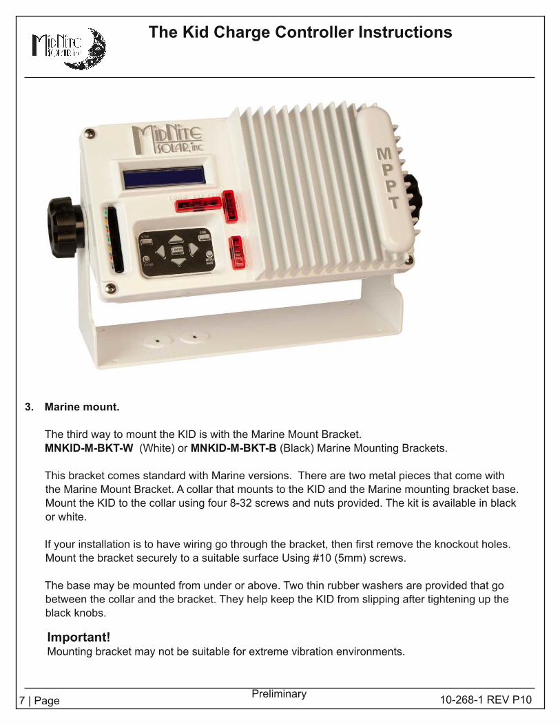
3. Marine mount.
The third way to mount the KID is with the Marine Mount Bracket.
MNKID-M-BKT-W (White) or MNKID-M-BKT-B (Black) Marine Mounting Brackets.
This bracket comes standard with Marine versions. There are two metal pieces that come with
the Marine Mount Bracket. A collar that mounts to the KID and the Marine mounting bracket base.
Mount the KID to the collar using four 8-32 screws and nuts provided. The kit is available in black
or white.
I f your instal lation is to have wiring go through the bracket, then first remove the knockout holes.
Mount the bracket securely to a suitable surface Using #1 0 (5mm) screws.
The base may be mounted from under or above. Two thin rubber washers are provided that go
between the collar and the bracket. They help keep the KID from slipping after tightening up the
black knobs.
Warnings. . . . . . . . . . . . . . . . . . . . . . . . . . . . . . . . . . . . . . . . . . . . . . . . . . . . . . . . . . . . . . . . . . . . . . . . . . . . . . . . . . . . . . . . . . . . . . 2The Kid Dimensions. . . . . . . . . . . . . . . . . . . . . . . . . . . . . . . . . . . . . . . . . . . . . . . . . . . . . . . . . . . . . . . . . . . . . . . . . . . . . 5Mounting The Kid. . . . . . . . . . . . . . . . . . . . . . . . . . . . . . . . . . . . . . . . . . . . . . . . . . . . . . . . . . . . . . . . . . . . . . . . . . . . . . . . . 5Wiring. . . . . . . . . . . . . . . . . . . . . . . . . . . . . . . . . . . . . . . . . . . . . . . . . . . . . . . . . . . . . . . . . . . . . . . . . . . . . . . . . . . . . . . . . . . . . . . . . . . 8Load Circuit. . . . . . . . . . . . . . . . . . . . . . . . . . . . . . . . . . . . . . . . . . . . . . . . . . . . . . . . . . . . . . . . . . . . . . . . . . . . . . . . . . . . . . . . . . 9Aux Input / Output. . . . . . . . . . . . . . . . . . . . . . . . . . . . . . . . . . . . . . . . . . . . . . . . . . . . . . . . . . . . . . . . . . . . . . . . . . . . . . . . 1 0MNBTS Battery Temperature Sensor. . . . . . . . . . . . . . . . . . . . . . . . . . . . . . . . . . . . . . . . . . . . . . . . . . . 1 2Stacking The Kid. . . . . . . . . . . . . . . . . . . . . . . . . . . . . . . . . . . . . . . . . . . . . . . . . . . . . . . . . . . . . . . . . . . . . . . . . . . . . . . . . . 1 2Set-Up and Use. . . . . . . . . . . . . . . . . . . . . . . . . . . . . . . . . . . . . . . . . . . . . . . . . . . . . . . . . . . . . . . . . . . . . . . . . . . . . . . . . . . 1 3Menus. . . . . . . . . . . . . . . . . . . . . . . . . . . . . . . . . . . . . . . . . . . . . . . . . . . . . . . . . . . . . . . . . . . . . . . . . . . . . . . . . . . . . . . . . . . . . . . . . . 1 3L.E.D. Legend. . . . . . . . . . . . . . . . . . . . . . . . . . . . . . . . . . . . . . . . . . . . . . . . . . . . . . . . . . . . . . . . . . . . . . . . . . . . . . . . . . . . . . 22Firmware Update. . . . . . . . . . . . . . . . . . . . . . . . . . . . . . . . . . . . . . . . . . . . . . . . . . . . . . . . . . . . . . . . . . . . . . . . . . . . . . . . . 22Wiring Diagrams. . . . . . . . . . . . . . . . . . . . . . . . . . . . . . . . . . . . . . . . . . . . . . . . . . . . . . . . . . . . . . . . . . . . . . . . . . . . . . . . . . 23HyperVOC.. . . . . . . . . . . . . . . . . . . . . . . . . . . . . . . . . . . . . . . . . . . . . . . . . . . . . . . . . . . . . . . . . . . . . . . . . . . . . . . . . . . . . . . . . . . 27Power Graph. . . . . . . . . . . . . . . . . . . . . . . . . . . . . . . . . . . . . . . . . . . . . . . . . . . . . . . . . . . . . . . . . . . . . . . . . . . . . . . . . . . . . . . . 28Accessories. . . . . . . . . . . . . . . . . . . . . . . . . . . . . . . . . . . . . . . . . . . . . . . . . . . . . . . . . . . . . . . . . . . . . . . . . . . . . . . . . . . . . . . . . . 28Whiz Bang Jr. Current Monitoring. . . . . . . . . . . . . . . . . . . . . . . . . . . . . . . . . . . . . . . . . . . . . . . . . . . . . . . . 31Warranty Information. . . . . . . . . . . . . . . . . . . . . . . . . . . . . . . . . . . . . . . . . . . . . . . . . . . . . . . . . . . . . . . . . . . . . . . . . . . . 33Specifications. . . . . . . . . . . . . . . . . . . . . . . . . . . . . . . . . . . . . . . . . . . . . . . . . . . . . . . . . . . . . . . . . . . . . . . . . . . . . . . . . . . . . . . 34Wall Mount Template. . . . . . . . . . . . . . . . . . . . . . . . . . . . . . . . . . . . . . . . . . . . . . . . . . . . . . . . . . . . . . . . . . . . . . . . . . . . 35
Important!Mounting bracket may not be suitable for extreme vibration environments.

8 | Page 1 0-268-1 REV P1 0
The Kid Charge Controller Instructions
Preliminary
+ - + -+ -
The Kid Terminal Block
PV/windInput
Load/Clipper
BatteryOut
The Kid Main Electrical Connections
The fol lowing pages contain wiring diagrams and system images.
Remove the back cover.
Remove the screw on the middle right of the back cover and gently remove the back cover.
The connections for PV/Wind input, Load/Clipper and Battery out are available on the terminal blockshown below, located inside The Kid on the backside of the circuit board.Observe polarity on all connections.
PV/Wind Input: Connections from the solar panels, wind or other AE sources go here.
Load/Clipper: Connections to the control led load (load control function) or dump load (ClipperFunction).
Battery Out: Connections to the battery bank go here.
Torque all connections to 7-9 inch pounds (0.80 - 1 .0 Nm).
Rear View of The Kid with the back cover removed.

9 | Page
The Kid Charge Controller Instructions
1 0-268-1 REV P1 0Preliminary
Wiring to the KID
Centered directly above the ½” conduit holes you wil l find the main 30 amp 6 position terminal block.
This is where you wil l connect PV input, loads (if any) and the battery bank. The battery bank should
use 1 0AWG wire (5.26mm2). On the included wiring diagrams you wil l notice an external 30 amp circuit
breaker in series with the battery plus wire. This is very important and is a requirement to meet NECguidel ines for overcurrent and disconnect devices. The battery overcurrent device regardless whether it
is a circuit breaker or fuse must be rated for the DC voltage rating of the battery bank. Fuses
incorporated into the KID are not to be used as these NEC required overcurrent devices. The internal
KID fuses are for internal KID operation only. MidNite Solar manufactures numerous circuit breaker
boxes for this use.
PV input overcurrent devices should fol low the NEC guidel ines of 1 .56 times short circuit current.
Therefore two 250 watt modules in series results in 8.87 amps of short circuit current (Isc) X 1 .56 =
1 3.83 amps. The NEC allows 1 5 amps through most 1 4AWG wire, so in this case 1 4AWG wire is
sufficient. Long distances (over 30 feet / 9 meters) may want to use larger wire to minimize voltage
drop. Now let’s take those same two solar panels and put them in paral lel . This configuration wil l result
in 1 7.7 Isc amps. Multiply this by 1 .56 = 27.6 amps. 1 0AWG wire is rated for 30 amps, so you would
need to switch to 1 0AWG wire for paral leled operation. The NEC requires a disconnect and overcurrent
protection on the PV input. Overcurrent protection can be a fuse or circuit breaker. Thermal circuit
breakers require the same 1 .56 times Isc, but MidNite solar hydraul ic/magnetic breakers require only
1 .25 times Isc. All MidNite din rai l and panel mount breakers are hydraul ic/magnetic and are rated to
hold 1 00% current. The use of a breaker is typical because you also get the required disconnect at the
same time. MidNite Solar manufactures Baby, Big Baby and Quad boxes to help comply with these
requirements.
The wiring diagrams included in these instructions also include another breaker in series with the PV
input breaker. This additional device is a DC-GFP. (ground fault protector). The NEC mandates the use
of DC-GFP’s in al l solar systems to help el iminate fires caused from faulty wiring. We find that the best
use for these devices is to find wiring errors made during the initial instal lation. MidNite Solar
manufactures the MNDC-GFP63 that fits in the Baby and Big Baby box along with a MNPV30 input
breaker. The Big Baby can also hold the battery breaker as discussed above. So one Big Baby box,
one MNDC-GFP63, and two MNEPV30 breakers fit the bil l for al l NEC required disconnects and
overcurrent devices.
Load circuit:
The load circuit is a multi-function circuit. Wiring of the loads if instal led wil l depend on the loads. There
is no de-rating of the overcurrent device, so if running a 20 amp load. You can use a 20 amp breaker and
1 2AWG wire. You can run a larger load such as a 400 watt inverter by using a 30 amp breaker and
1 0AWG wire. The overcurrent device for the loads can be housed in a Baby, big Baby or Quad box. See
the wiring diagrams at the end of this manual for more detai ls.
1 0 | Page 1 0-268-1 REV P1 0
The Kid Charge Controller Instructions
Preliminary
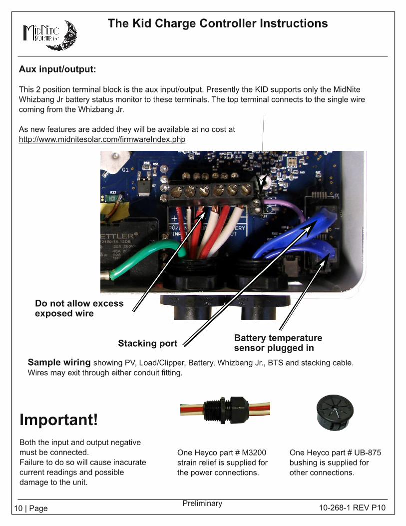
Aux input/output:
This 2 position terminal block is the aux input/output. Presently the KID supports only the MidNite
Whizbang Jr battery status monitor to these terminals. The top terminal connects to the single wire
coming from the Whizbang Jr.
As new features are added they wil l be available at no cost at
http: //www.midnitesolar.com/firmwareIndex.php
Stacking portBattery temperaturesensor plugged in
Do not allow excessexposed wire
Sample wiring showing PV, Load/Clipper, Battery, Whizbang Jr. , BTS and stacking cable.
Wires may exit through either conduit fitting.
One Heyco part # M3200
strain rel ief is supplied for
the power connections.
Important!Both the input and output negative
must be connected.
Failure to do so wil l cause inacurate
current readings and possible
damage to the unit.
One Heyco part # UB-875
bushing is supplied for
other connections.

11 | Page
The Kid Charge Controller Instructions
1 0-268-1 REV P1 0Preliminary
Chassis Ground connection
The screw, nut and terminal for grounding the chassis are included on all models.
The chassis ground (equipment ground) is required in an NEC compliant system. The chassis of the
KID is isolated from all internal KID circuitry.
Wiring the rest of the system :
Under the “Wiring diagrams” section of this manual there are seven different system configurations.
1 2, 24 and 48VDC systems are shown. These diagrams are based on common solar panels rated
between 230 and 250 watts each, and a VOC of about 37 volts. (60 cell modules). These diagrams
cover 95% of all combinations that wil l be used with the KID. Other solar panels are available and can
certainly be used with the KID. Study the wiring diagrams to find the one that best suits your needs.
You wil l see from 2 to 6 solar panels depending on system design and battery voltage. In a 1 2V
system you wil l be l imited to just two of these solar panels. The reason is that the KID has an absolute
maximum output of 30 amps. Power is amps X voltage, so 30 amps output times 1 4 volts (charge
voltage) = 420 watts. A 500 watt PV array would be a good match for a 1 2V system. You can always
start with a smaller PV array and add to it at a later date. Keep in mind that PV voltage and current
need to be matched closely in most cases. See the power graph at the end of this section. Battery
voltage for the KID can be 1 2, 24 or 48 volts, so that means when you jump to a 24V battery bank, the
KID can process twice the power than if it were connected to a 1 2V battery. In the case of a 48V
battery, the KID can process 4 times the power of a 1 2V battery. Twelve volt batteries are used in
marine and RV and very small Renewable Energy systems. When possible, it is better to go with a
higher voltage battery bank, but that is usually not possible in a mobile application.

1 2 | Page 1 0-268-1 REV P1 0
The Kid Charge Controller Instructions
Preliminary
MNBTS Battery Temperature sensor
Standard on Marine versions, optional on All others. The published ratings of batteries are all made at
77 degrees F (25C). Mother nature as well as man doesn’t always allow the ambient temperature to
hover around 25C while charging batteries. Battery temperature sensors are employed on many
sophisticated chargers in order to compensate the charge voltage based on temperature. I f you are in
an area where the ambient temperature is relatively stable at this temperature, you do not need a BTS
(Battery Temp Sensor). I f you l ive in Alaska or in the Sahara desert, you wil l want a BTS. I t wil l prolong
the l ife of your batteries. The BTS raises the charge voltage when colder than 77 degrees C and
decreases the charge voltage above 77 degrees F.
Temp comp is set for lead acid batteries, but is adjustable for other types in the Battery menu.
Stack port:
The KID stacking port is a special jack used for two things. When your power requirements grow and
more charging current is required, you can add a second KID and have it act l ike a 60 amp control ler.
This requires that the PV input and battery output be paral leled, You accomplish this outside of the
KID in a suitable junction box. Programming is required to tel l the KID that it is now stacked. Make
sure to use wire and breakers of suitable size for each KID. Since you wil l now have a 60 amp output
capabil ity, you might think that a single 60 amp breaker after combining the output is acceptable?
However, each KID accepts 1 0AWG wire max. A 60 amp breaker does not protect 1 0AWG wire, so
two 30 amp breakers wil l be required. The same situation exists for the PV input. Make sure that
wires are not too small for the overcurrent devices.
1 4AWG = 1 5 amp breaker
1 2AWG = 20 amp breaker
1 0AWG = 30 amp breaker
8AWG = 50 amp breaker
6 AWG = 60 amp breaker

1 3 | Page
The Kid Charge Controller Instructions
1 0-268-1 REV P1 0Preliminary
Set-Up and Use
Serial communications from the stack port:
In the future you wil l be able to get serial data from the stack port. You cannot have a stacked pair of
KIDS and serial data at the same time however. Firmware can be downloaded to upgrade the KID
features at http: //www.midnitesolar.com/firmwareIndex.php.
Now that your KID is al l wired up, solar panels in place and connected, battery bank instal led and any
loads connected, it is time to turn things on.
Get a digital meter. They can be had for as low as $4.00 at Harbor freight, so there is no excuse to not
have one. You wil l need one if support is ever required.
Check list:
Make sure all breakers are off. You didn’t have them turned on while wiring did you?
Measure the battery voltage to insure you don’t have a bad battery or bad connections. Read from
Battery plus to battery minus to get your nominal voltage. A 1 2V battery should read between 11 .5 and
1 3.00. By the way if it does read below 1 2V, that is not a good sign! Then measure it again at the KID
terminals. I t should be the same as at the battery.
Measure the output of the PV array from the PV minus to the PV plus at the point of connection at the
PV input breaker. Then turn the PV input breaker on and measure at the KID terminal block PV+ to PV
-. A 60 cell module should read about 37VDC. Two in series wil l read about 74. Three in series should
read about 111 . Don’t worry if you are off by 1 0% or so.
Please do make sure that the panels are pointed at the sun, that the sun is completely on each panel
with no shading and you are not inside of a garage. The sun must be il luminating the entire solar panel
(s). You would be surprised how many people don’t understand this concept. Our tech support people
talk to them all the time. I t is easy to avoid this situation.
Leave your Load breaker off for the moment.
Turn on the battery breaker. I f this is the first time it has been turned on, you wil l see this:
I f your battery voltage is 1 2V, then hit the right arrow key to advance to the next set up selection. I f you
have a different battery voltage than what is displayed, then hit the up or down arrow key unti l the desired
nominal battery voltage is displayed. Once the correct voltage is displayed, hit the right arrow key.

1 4 | Page 1 0-268-1 REV P1 0
The Kid Charge Controller Instructions
Preliminary
The next set of screens are where you select battery type. Selecting the applicable battery type sets
some important parameters that are specific to different battery chemistries. The first choice is
Lithium. Use the up arrow to see all the choices. Listed below.
Stop on the correct battery type and then hit the right arrow
key. I t then takes you to the absorb voltage screen.

1 5 | Page
The Kid Charge Controller Instructions
1 0-268-1 REV P1 0Preliminary
When the absorb screen appears, use the up/down arrow to adjust absorb voltage. Consult your battery
manufacturer for their recommended settings. There is no such thing as one setting that fits al l flooded
or AGM etc. batteries. Different manufacturers have different requirements. Differences may be subtle,
but the KID is capable of very fine adjustment. There is no reason to guess as to these important
settings. When done, hit the right arrow key to go to the Float settings screen.
Setting the Float voltage is accomplished exactly the same as the previous Absorb voltage. Use the up
down arrows to adjust the float voltage according to your battery manufacturer’s recommendations.
When done, hit the right arrow key to bring you to the Equalize screen.
Default is 1 5.0 volts. This is not high enough to EQ a flooded battery, but not so high that it would hurt
a Gel or AGM style battery which is why the EQ default setting is intentional ly set low. Flooded
batteries require periodic Equalizing to reduce sulfation. Consult your battery manufacturers
specifications for a correct EQ setting. I f your type of battery does not want to ever be EQ’d, then
simply set the voltage to the Absorb voltage.
When done, hit the right arrow key to bring you to the Input Function screen.
This screen is where you select what type of charge control ler you wil l configure the KID for. Solar
is the most common. Use the up /down arrow keys to select Solar, Wind or Hydro, then hit the right
arrow key. The screen changes to say DATA HAS BEEN SAVED and then switches to a status
screen.

1 6 | Page 1 0-268-1 REV P1 0
The Kid Charge Controller Instructions
Preliminary
Your KID is now set up for al l the required settings. There are sti l l two more things to do before it can
start charging.
1 . Turn on the PV input breaker so the KID has PV array voltage applied.
2. The KID is not yet turned on, so you wil l need to turn it on. To turn the KID on, you wil l need to get
to the INPUT Main Menu. Use the right arrow key to go to the INPUT menu and push enter.
Assuming this is a solar control ler and assuming that it booted up in the off position, hit the right
arrow key. You wil l hear the relay cl ick and turn on. Hit the save button. The KID is now on, so hit
the status button and see what it is doing. Use the right/left arrow keys to scrol l through the
different status screens.
MAIN MENUS:
The KID has 7 MAIN MENU headings. This section deals with the MAIN MENU headings only.
See INSIDE THE MAIN MENUS for what is inside each of the 7 menus.
Hit the MENU/BACK key. This button takes you to all of the Main Menus. Main menus are something
you want to become famil iar with. No matter where you are at in any menu, you can always get to the
Main Menus by hitting this button once or twice.
You scrol l through Main Menus from left to right. The left most Main Menu is as fol lows.
Notice the word BATTERY is in brackets. That means the BATTERY menu wil l be activated if the
ENTER button is pushed. The BATTERY menu allows you to set al l battery charging parameters just
l ike what was done in the initial set up.
The BATTERY menu has additional adjustments beyond what the initial set up had. After the first time
activating the KID, this is the way to change Battery charging parameters.
The adjustment and settings available inside the BATTERY menu are:
Absorb voltage settings
Float voltage settings
Equalize voltage settings
Amp limits for battery charging and load draw
Temperature compensation adjustabil ity
Temp comp during EQ
1 7 | Page
The Kid Charge Controller Instructions
1 0-268-1 REV P1 0Preliminary
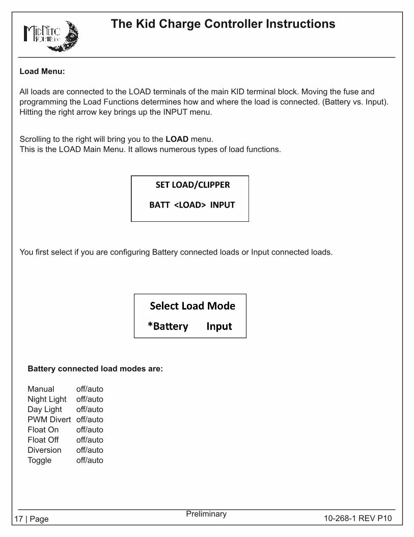
Scrol l ing to the right wil l bring you to the LOAD menu.
This is the LOAD Main Menu. I t al lows numerous types of load functions.
Battery connected load modes are:
Manual off/auto
Night Light off/auto
Day Light off/auto
PWM Divert off/auto
Float On off/auto
Float Off off/auto
Diversion off/auto
Toggle off/auto
Load Menu:
All loads are connected to the LOAD terminals of the main KID terminal block. Moving the fuse and
programming the Load Functions determines how and where the load is connected. (Battery vs. Input).
Hitting the right arrow key brings up the INPUT menu.
You first select if you are configuring Battery connected loads or Input connected loads.

1 8 | Page 1 0-268-1 REV P1 0
The Kid Charge Controller Instructions
Preliminary
Clipper Mode:
The INPUT selection wil l al low the input to be connected to a voltage limiter cal led a CLIPPER.
This special CLIPPER mode is used in conjunction with wind turbines. The special CLIPPER
Diversion load is connected up to the input of the KID when the fuse is moved from the LOAD position
to the CLIPPER position.
This fuse is located directly underneath of the LCD display. The CLIPPER diversion load is more than
a simple resistor.
The MidNite Solar Clipper Diversion load must be used with wind turbines or overvoltage damage to
the KID may result.
Input connected loads:
Low Battery Disconnect:
The kid includes an adjustable Low battery Disconnect function which allows the user to set an
absolute discharge limit when using a daily function such as Night Light and the l ife of the batteries
doesn't want to be compromised, it also includes a reconnect voltage set point or it could be
reconnected when Float has been reached, ensuring that the batteries have been ful ly charged after
a LBD (Low Battery Disconnect).
I f a LBD state has occurred the blue LED wil l bl ink slowly.
To set up these parameters:
-Press Main Menu button
-Scrol l to the right and select <Load> and press Enter
-Press the Setup button
-I f OFF appears under the names Lowbatt and Reconn it means the feature is currently disabled.
-Press the Right button to enable the function, now two numbers wil l appear under the names
-Press the Left, Right, Up and Down keys to adjust the voltages as needed for your battery type
-To enable reconnect on Float stage go to Reconn and Press the Right key again and the word
FLOAT wil l appear under Reconn (Float voltage can be configured in the Battery menu).
-Press the Save button to keep the changes on non volati le memory of The Kid.
Refer to the battery manufacturers recommended settings.

1 9 | Page 1 0-268-1 REV P1 0
The Kid Charge Controller Instructions
Preliminary
The INPUT MENU is where you turn the KID on and off. There are 1 0 different selections for how
the KID wil l track your Solar, Wind or Hydro system. Selections are below:
Solar Learn off/on The main Solar algorithm
Wind Track* off/on Wind mode for known turbines
Micro Hydro* off/on Slight variation of tracking specifical ly for small hydro systems
Wind Learn* off/on A learning program that learns over time an unknown turbine
Legacy P&O off/on The old tried and true perturb and observe. Not fast, but good
U-SET Voc off/on Allows you to pick the PWM percentage of Voc. Good for testing
Solar1 O&P off/on The opposite of P&O
* Future feature
Hit the right arrow to advance to the AUX MAIN MENU .
The AUX menu is where you set up various auxil iary input and output functions such as the
Whizbang Jr. Battery status monitor.
Hit the right arrow key to advance to the MISC menu.
The MISC menu allows adjustment for:
LCD Backlight and contrast controls can be adjusted with the up/down buttons
Temp Status of CPU, FET and Battery in degrees C
LED MODE BCM (battery capacity meter) Rick mode (minimal l ights) and Off
Timer Shows time accrued.
Input Menu:
20 | Page
The Kid Charge Controller Instructions
1 0-268-1 REV P1 0Preliminary
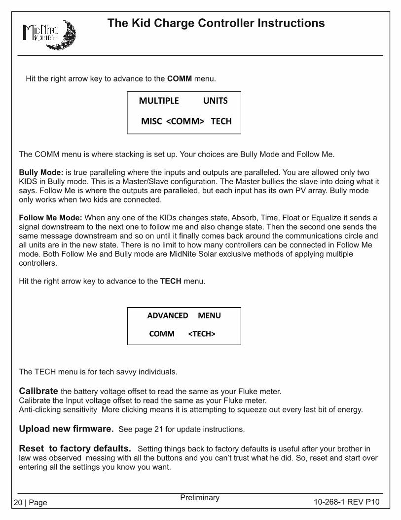
Hit the right arrow key to advance to the COMM menu.
The COMM menu is where stacking is set up. Your choices are Bully Mode and Follow Me.
Bully Mode: is true paral lel ing where the inputs and outputs are paral leled. You are allowed only twoKIDS in Bully mode. This is a Master/Slave configuration. The Master bul l ies the slave into doing what itsays. Follow Me is where the outputs are paral leled, but each input has its own PV array. Bul ly modeonly works when two kids are connected.
Follow Me Mode: When any one of the KIDs changes state, Absorb, Time, Float or Equalize it sends asignal downstream to the next one to fol low me and also change state. Then the second one sends thesame message downstream and so on unti l i t final ly comes back around the communications circle andall units are in the new state. There is no limit to how many control lers can be connected in Follow Memode. Both Follow Me and Bully mode are MidNite Solar exclusive methods of applying multiplecontrol lers.
Hit the right arrow key to advance to the TECH menu.
The TECH menu is for tech savvy individuals.
Calibrate the battery voltage offset to read the same as your Fluke meter.Calibrate the Input voltage offset to read the same as your Fluke meter.Anti-cl icking sensitivity More clicking means it is attempting to squeeze out every last bit of energy.
Upload new firmware. See page 21 for update instructions.
Reset to factory defaults. Setting things back to factory defaults is useful after your brother inlaw was observed messing with al l the buttons and you can’t trust what he did. So, reset and start overentering al l the settings you know you want.

21 | Page 1 0-268-1 REV P1 0
The Kid Charge Controller Instructions
Preliminary
STATUS BUTTON: There are a few status screens available at the touch of the Status button.
The first (left) screen shows:
The 9.5a as depicted above represents the PV array output current.
BULKMPPT shows the state that the charger is in. BULKMPPT means the KID is going all out to put al l
available energy into the batteries.
Other states are:
RESTING This is what happens when the PV array voltage is too low to do any charging.
The 1 2.7V represents battery voltage.
The SOLAR shows it is in Solar mode as opposed to Wind or Hydro.
The 257W shows the instantaneous wattage going into the battery.
push the right arrow key to bring up the second status screen shown below.
This second status screen is showing the PV array voltage and battery voltage. The PV array voltage
corresponds to the Max power voltage from the PV array for the present conditions.
Push the right arrow key to bring up the third status screen.
This third status screen is showing.
Note: Some features l isted in this manual are not yet functional. Keep your eye onwww.midnitesolar.com for updates in KID firmware.

22 | Page
The Kid Charge Controller Instructions
1 0-268-1 REV P1 0Preliminary
The Kid's L.E.D.s.
RFC - Received Full Charge. Thebattery has received a ful l charge.
1WK - One Week. I t has been oneweek since a ful l charge.
2WK - Two Weeks. I t has been twoweeks since a ful l charge.
FLT - Float. The battery is in floatcharge.
OVR - Over Voltage.The kid hasdetected an overvoltage.
ERR - Error.The kid has stoppeddue to an error.
CLP - Clipper.The kid is in ClipperMode.
The Kid has several L.E.D.s to indicate
modes and errors.
Not al l L.E.D.s are implemented at this
time.
Firmware Update
To do a firmware update on the kid you wil l need the fol lowing:
- A laptop or PC with Windows 7 (Windows 7 only at this time )
- A USB Mini-A cable (not included).
Procedure:
- Go to http: //www.midnitesolar.com/firmwareIndex.php and download the latest firmware fi le.
- Save the fi le to a known location on your PC (eg. Desktop \).
- Plug in the USB cable to the Kid connector located on the bottom of the unit.
- Plug the other end into an available USB port on the PC.
- Go to MAIN Menu on the Kid And scrol l to the right to the TECH menu and press Enter.
- Press the down arrow key unti l Firmware Update is selected and press Enter.
- After 5 sec the unit wil l turn off and display FIRMWARE UPDATE.
- A new empty drive wil l appear in your PC open it.
- Drag the downloaded fi le to this empty drive.
- The first green light should start bl inking on the Kid and "UPDATING.. . ' should appear on the
second line.
- I t wil l take up to 2 minutes to update the kid.
- The unit wil l reboot with new updated firmware.
- Unplug the USB cable.

23 | Page
The Kid Charge Controller Instructions
1 0-268-1 REV P1 0Preliminary
Wiring Diagrams
1 2 Volt Systemwith two solarpanels in series
1 2 Volt Systemwith two solarpanels inparal lel
Importan
t!Boththeinputandoutputnegativemustbe
connected.
Failuretodosowillcauseinacuratecurrent
readingsandpossibledamagetotheunit.
Importan
t!Boththeinputandoutputnegativemustbe
connected.
Failuretodosowillcauseinacuratecurrent
readingsandpossibledamagetotheunit.

24 | Page 1 0-268-1 REV P1 0
The Kid Charge Controller Instructions
Preliminary
24 Volt Systemwith two solarpanels in series
24 Volt Systemwith three solarpanels inSeries
Importan
t!Boththeinputandoutputnegativemustbe
connected.
Failuretodosowillcauseinacuratecurrent
readingsandpossibledamagetotheunit.
Importan
t!Boththeinputandoutputnegativemustbe
connected.
Failuretodosowillcauseinacuratecurrent
readingsandpossibledamagetotheunit.
25 | Page
The Kid Charge Controller Instructions
1 0-268-1 REV P1 0Preliminary
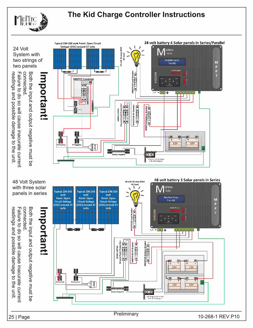
24 VoltSystem withtwo strings oftwo panels
48 Volt Systemwith three solarpanels in series
Importan
t!Boththeinputandoutputnegativemustbe
connected.
Failuretodosowillcauseinacuratecurrent
readingsandpossibledamagetotheunit.
Importan
t!Boththeinputandoutputnegativemustbe
connected.
Failuretodosowillcauseinacuratecurrent
readingsandpossibledamagetotheunit.

26 | Page 1 0-268-1 REV P1 0
The Kid Charge Controller Instructions
Preliminary
48 Volt Systemwith two stringsof three panels
Two Kidsparal leled withstacking cable
The string sizing tool is atwww.midnitesolar.com
Importan
t!Boththeinputandoutputnegativemustbe
connected.
Failuretodosowillcauseinacuratecurrent
readingsandpossibledamagetotheunit.
Importan
t!Boththeinputandoutputnegativemustbe
connected.
Failuretodosowillcauseinacuratecurrent
readingsandpossibledamagetotheunit.

27 | Page
The Kid Charge Controller Instructions
1 0-268-1 REV P1 0Preliminary
HyperVOCThe Kid includes HyperVOC
a non-operative VOC safety zone over and
above the maximum input voltage
Why do you need HyperVOC?
On cold mornings PV panels wil l put out ful l voltage even before you can see the
sun. Ambient l ight may not have much current behind it but it does have voltage
thay may exceed the operating voltage limit of the control ler, resulting in damage to the control ler.
The fact that there is no power behind the output voltage means that the control ler wil l not be able to
turn on and drag the panels down from VOC to max power voltage.
The control ler requires a few watts of power coming in from the PV panels to overcome
its internal power requirements. While the control ler is waiting for enough power to
wake up, the PV array is at its highest output voltage. This is very dangerous if the
maximum operating voltage of the control ler is exceeded.
TheKidSolar control ler gives you bonus headroom for those cold mornings that
would potential ly destroy any other control ler. We have advised thousands of customers
to play it safe in conditions l ike our example above. MidNite has a unique characteristic
of the circuitry that al lows it to go beyond the maximum operating voltage for
these conditions, it’s cal led HyperVOC.
Do not abuse the HyperVOC zone though. For example, let’s take a Kid configured
with 4 modules in series that have 36.9 VOC, 4 x 36.9 = 1 47.6. In Alberta with a
-32°C temperature, the max VOC wil l reach 1 81 .54. This is well within the HyperVOC
zone on a 48V battery bank.
Above: HyperVOC voltage limits above normal
operating voltage.
Right: Solar Panel VOC adjustments by
temperature.
28 | Page
The Kid Charge Controller Instructions
1 0-268-1 REV P1 0Preliminary
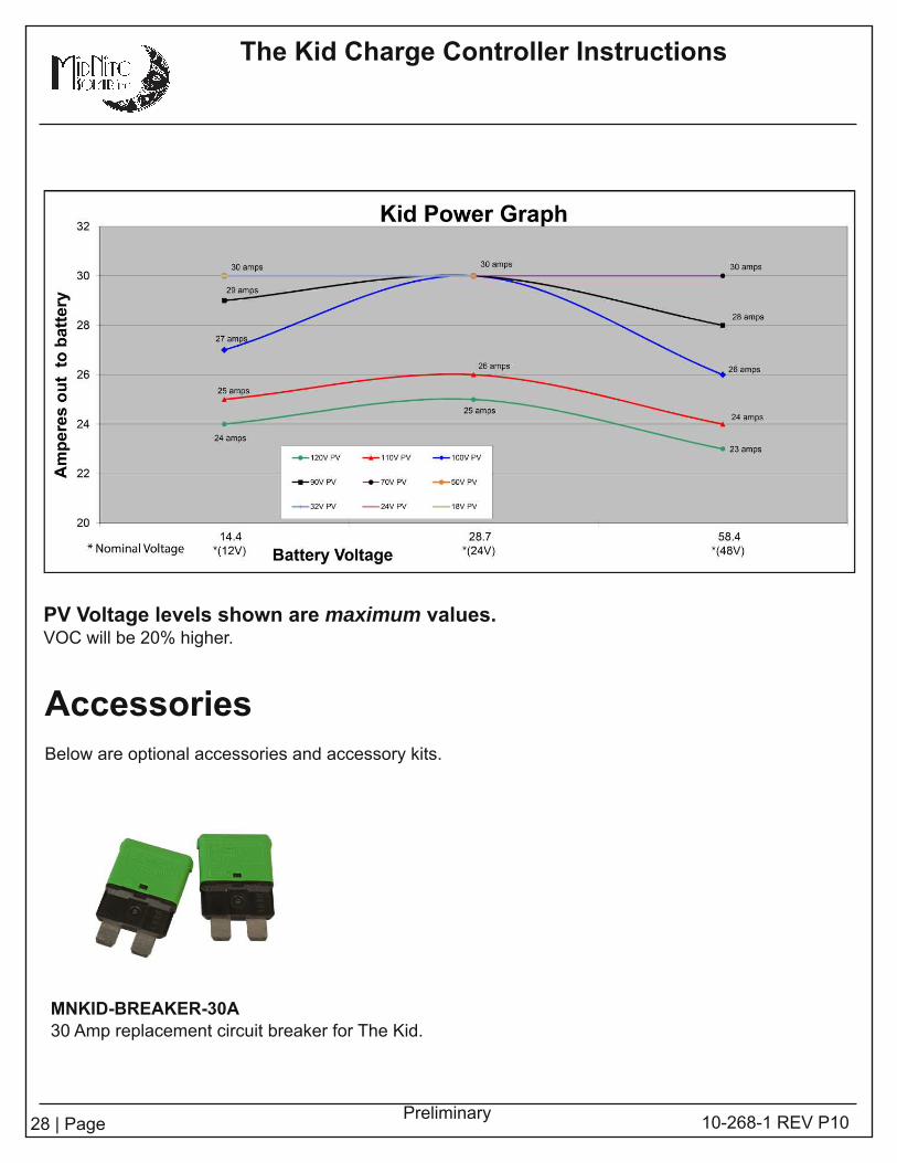
PV Voltage levels shown are maximum values.VOC wil l be 20% higher.
AccessoriesBelow are optional accessories and accessory kits.
MNKID-BREAKER-30A30 Amp replacement circuit breaker for The Kid.

29 | Page 1 0-268-1 REV P1 0
The Kid Charge Controller Instructions
Preliminary
MNKID-ASSY-KIT-B (Black) or MNKID-ASSY-KIT-W (White) Accessory kit
Kit includes:
Black or white mounting bracket
Flexible conduit
Straight and 90° Conduit fittings
MNBTS Battery temperature sensor
Hardware to attach mounting bracket to The Kid
MNKID-WMB-B (Black) or MNKID-WMB-W (White) Wall Mount kit
Kit includes:
Black wall mounting bracket
Hardware to attach mounting bracket to The Kid.
Accessories Continued

30 | Page
The Kid Charge Controller Instructions
1 0-268-1 REV P1 0Preliminary
Accessories Continued
MNBCM / MNBCMS : Battery Status Monitor
1 . LEDs that correspond to battery voltage
2. Voltage accuracy +- .05%
3. Auto sensing for 1 2, 24, 36, and 48 volt batteries
4. LED indicators show if batteries have received a ful l charge recently, longer than one week or
longer than two weeks
5. Ideal for "at a glance" readings - golf carts, forkl ifts, etc.
Description: Battery Capacity Meter
Size 4.5"L x 3.75"W x 1 "D
Box Size 5"L x 4"W x 2"D
Weight 1 Lb.
MNHydrometer
Easy to use battery hydrometer for checking the
specific gravity on all "Flooded" style batteries.
Size: 5.25"L x 4.25"W x 1 .5"D

31 | Page 1 0-268-1 REV P1 0
The Kid Charge Controller Instructions
Preliminary
Whiz Bang Jr.:
The Whiz Bang Jr. is designed to work with The Kid to give accurate battery status.
The Whiz Bang Jr. keeps track of Amp-Hours going into and out of the battery.
Simple one-wire instal lation.
Shunt not included.
The Whiz Bang Jr can provide shunt access for co-operative products.
Accessories Continued

32 | Page
The Kid Charge Controller Instructions
1 0-268-1 REV P1 0Preliminary
Big Baby Quad
MNDCGFP-63
MNEPVBreaker MNEDC
Breaker
Optional Circuit Breakers and Accessories
The Big Baby is an aluminumpowder coated breaker enclosurethat holds four DINRail breakers.
The Quad is an aluminum powdercoated breaker enclosure that holdsfour panel mount breakers.
63 amp 1 50VDC din rai l mount DCground fault protector (NRTL listedbreaker assy).NEC2008 requires DC-GFP’s on allsolar instal lations
1 50VDC din rai l mount breaker (1 3mm wide).MNEPV evaluated by ETL to 1 50VDC.1 50VDC ETL listed in the US and Canada1 0,000 AIC.
DC Panel mount breaker availableup to 1 00 amps.
More circuit breakers and
accessories available at
www.midnitesolar.com
MNEACBreaker
1 20V AC DINrail breaker availablein a wide range of Amperages.

33 | Page
The Kid Charge Controller Instructions
1 0-268-1 REV P1 0Preliminary
MidNite Solar Inc. warrants to the original customer that its products shall be free fromdefects in materials and workmanship. This warranty wil l be valid for a period of two (2) years.
At its option, MidNite Solar wil l repair or replace at no charge any MidNite product thatproves to be defective within such warranty period. This warranty shall not apply if theMidNite Solar product has been damaged by unreasonable use, accident, negl igence,service or modification by anyone other than MidNite Solar, or by any other causesunrelated to materials and workmanship. The original consumer purchaser must retainoriginal purchase receipt for proof of purchase as a condition precedent to warrantycoverage. To receive in-warranty service, the defective product must be received no laterthan two (2) weeks after the end of the warranty period. The product must be accompaniedby proof of purchase and Return Authorization (RMA) number issued by MidNite Solar.For an RMA number contact MidNite Solar Inc. , 1 7722 67th Ave NE, Arl ington, WA98223 (360) 403-7207.
Purchasers must prepay all del ivery costs or shipping charges to return any defectiveMidNite Solar product under this warranty policy. Except for the warranty that the productsare made in accordance with, the specifications therefore supplied or agreed to bycustomer:
MIDNITE SOLAR MAKES NO WARRANTY EXPRESSED OR IMPLIED, AND ANYIMPLIED WARRANTY OF MERCHANTABILITY OR FITNESS FOR A PARTICULARPURPOSE WHICH EXCEEDS THE FOREGOING WARRANTY IS HEREBY DISCLAIMEDBY MIDNITE SOLAR AND EXCLUDED FROM ANY AGREEMENT MADE BYACCEPTANCE OF ANY ORDER PURSUANT TO THIS QUOTATION. MIDNITE SOLARWILL NOT BE LIABLE FOR ANY CONSEQUENTIAL DAMAGES, LOSS OR EXPENSEARISING IN CONNECTION WITH THE USE OF OR THE INABILITY TO USE ITS GOODSFOR ANY PURPOSE WHATSOEVER. MIDNITE SOLAR’S MAXIMUM LIABILITY SHALLNOT IN ANY CASE EXCEED THE CONTRACT PRICE FOR THE GOODS CLAIMED TOBE DEFECTIVE OR UNSUITABLE.
Products wil l be considered accepted by customer unless written notice to the contrary isgiven to MidNite Solar within ten (1 0) days of such delivery to customer. MidNite Solar shallnot in any case be liable for any event occurring or defect discovered with regard to saidproduct unless written notice thereof is given to MidNite Solar within one hundred eighty(1 80) days of such product del ivery to customer. MIDNITE SOLAR is not responsible forloss or damage to products owned by customer and located on MIDNITE SOLAR’Spremises caused by fire or other casualties beyond MIDNITE SOLAR’s control. Thiswarranty is in l ieu of al l other warranties expressed or implied.
MIDNITE SOLAR INC. 1 7722 67TH AVE NE ARLINGTON, WA 98223Email : [email protected]: 360-403-7207 FAX: 360-691 -6862
Warranty

34 | Page 1 0-268-1 REV P1 0
The Kid Charge Controller Instructions
Preliminary

35 | Page
The Kid Charge Controller Instructions
1 0-268-1 REV P1 0Preliminary
Wall Mounting Template
Tousethistemplate:
Removetemplatefromthemanualandsecuretothewallwith
alowtacktapesuchasscotchormaskingtape.
Othertapesaremorelikelytosticktothepaintwhentheyareremoved.Removealltapewithin24hours.
Makesurethatthetemplateisflatandnotcrooked.
Usealargedrill
insidethecut-outareatocreateanentry
pointforthesaw.Useadrywallorjig
sawandcutalongthedottedlines
usingcautionespeciallyaroundthecorners.
Drill
thefourcornerholeswith
thesmallestdrill
thatwillworkwith
yourhardware.Usecautiontoavoidbreakingthroughtothelarge
cut-outarea.
PutTheKidinplaceandsecurewith
appropriatehardware.
Photocopiesofthetemplatemaynotbeaccurateandshouldbeavoided.
4.54
8.675
9.275
8.763
5.01 0
4.50
Related Documents


