USER'S MANUAL IM-EESIFLO-5000V1-EN ULTRASONIC FLOWMETER 165 ø 4,50 10 11 12 13 14 1 2 3 4 5 6 7 8 9 PE N(-) L(+) EESIFLO 5000 SERIES FLOWMETER www.eesiflo.com BRK CLR ENTER RESET MARKED OR WHITE CABLE TRANSDUCER PROCESS OUTPUTS BINARY B1 INIT POWER SUPPLY OBSERVE LABEL! LINE FUSE PE BINARY B2 CURRENT l1 RS485

Welcome message from author
This document is posted to help you gain knowledge. Please leave a comment to let me know what you think about it! Share it to your friends and learn new things together.
Transcript

USER'S MANUAL IM-EESIFLO-5000V1-EN
ULTRASONIC FLOWMETER
165ø 4,50
10 11 12 13 14 1 2 3 4 5 6 7 8 9 PE N(-) L(+)
EESIFLO 5000 SERIES FLOWMETER
www.eesiflo.com
BRK CLR ENTER
RESET
MARKED OR WHITE CABLE
TRANSDUCER PROCESS OUTPUTS
BINARYB1
INIT
POWER SUPPLYOBSERVE LABEL!
LINE FUSEPEBINARY
B2CURRENT
l1RS485

EESIFLO 5000 Firmware V5.xx

USER'S MANUAL IM-EESIFLO-5000V1-EN
Remarks:
IBM is a protected trademark of International Business Machines Corporation.
MS-DOS, Excel, Windows are trademarks of Microsoft Corporation.

EESIFLO can be operated in the language of your choice. Please refer to chapter 5.6.
EESIFLO blendet seine Anzeigen in einer durch Sie zu
wählenden Sprache ein. (Siehe Kapitel 5.6).
Il est possible de sélectionner la langue utilisée par EESIFLO à
l'écran. Veuillez consulter le chapitre 5.6.
EESIFLO puede ser manejado en el idioma de su elección. Consulte el
capítulo 5.6.


IM-EESIFLO-5000V1-EN, 02.03.03 1
Table of Contents1 Introduction 3
1.1 Regarding this Manual 3 1.2 Safety Precautions 3 1.3 Warranty 3
2 The Flowmeter 5 2.1 Overview 5 2.2 Measuring Principle 5 2.3 Applications 6 2.4 Description of the Flowmeter 7 2.5 The Transducers 8 2.6 Serial Number 8
3 Handling 9 3.1 Scope of Delivery 9 3.2 General Precautions 9 3.3 Maintenance 9 3.4 Cleaning 9
4 Installation of EESIFLO 5000 11 4.1 Location 11 4.2 Mounting 11 4.3 Wiring 11
5 Getting Started 15 5.1 Instrument Start-Up 15 5.2 The Keyboard 15 5.3 The Menus 16 5.4 Command Execution during
Measurement 17 5.5 HotCodes 17 5.6 Selecting the Language 18 5.7 Interruption of Power Supply 18
6 Selection of the Measuring Point 21 6.1 Acoustic Propagation 21 6.2 Undisturbed Flow Profile 21 6.3 Points to Avoid 23
7 Basic Measurement 25 7.1 Input of the Pipe's Parameter 25 7.2 Input of the Medium's Parameters 27 7.3 Other Parameters 29 7.4 Selection of the Sound Path Factor 29 7.5 Mounting and Positioning
the Transducers 30 7.6 Starting the Measurement 34 7.7 Recognition of Flow Direction 34 7.8 Stopping the Measurement 34
8 Displaying the Measured Values 35 8.1 Selection of the Physical Quantity and
of the Unit of Measurement 35 8.2 Configuration of the Display 35 8.3 Transducer Distance 36
9 Advanced Measuring Functions 37 9.1 Command Execution during
Measurement 37 9.2 The Damping Factor 37 9.3 Flow Totalizers 37 9.4 Upper Limit for Flow Velocities 39 9.5 Cut-off Flow 39 9.6 Uncorrected Flow Velocity 40 9.7 Limit Values for the
Transducer Parameters 41 9.8 Protection against Interruption 41
10 Libraries 43 10.1 Editing the Selection Lists 43 10.2 Defining New Materials and Media 45
11 Settings 53 11.1 Setting the Internal Clock 53 11.2 Settings for the Dialogues and Menus 54 11.3 Measurement Settings 56 11.4 Setting the Contrast 57 11.5 Instrument Information 57
12 SuperUser Mode 59 12.1 Activating/Deactivating 59 12.2 Transducer Parameters 59 12.3 Malfunctions in SuperUser Mode 60
13 Measuring the Sound Velocity of the Medium 61
13.1 Displayed Information 62 14 Process Outputs 65
14.1 Installation of a Process Output 65 14.2 Defining the Error Value Delay 69 14.3 Activation of an Analogue Output 69 14.4 Activation of a Pulse Output 70 14.5 Activation of an Alarm Output 71 14.6 Operation of the Alarm Outputs 73 14.7 Deactivating the Outputs 75
15 Troubleshooting 77 15.1 Problems with the Measurement 78 15.2 Correct Selection of the
Measuring Point 78 15.3 Maximal Acoustic Contact 79 15.4 Application Specific Problems 79 15.5 Measurement Data Substantially Differ
from the Expected Value 79 15.6 Problem with the Totalizers 80
A Specifications 81 B Overview of the Firmware 85
C Reference 87

2 IM-EESIFLO-5000V1-EN, 02.03.03
IM-EESIFLO-5000V1-EN, 02.03.03 3
1 Introduction
1.1 Regarding this Manual This manual has been written for the personnel operating an EESIFLO flowmeter.It contains very important information about the instrument, how to handle it correctly, how to avoid damaging it and how to avoid injury. Always keep this manual at hand. Get acquainted with the safety rules and the handling precautions. Make sure you have read and understood this manual before using the instrument. The basic functions of the instrument are explained in chapter 5.
All reasonable effort has been made to ensure the correctness of the content of this manual. Should you however find some erroneous information, please inform us.
Please note that we shall be grateful for any suggestions and comments regarding the EESIFLO concept and your experience working with the instrument. This will ensure that we can further develop our products for the benefit of our customers and in the interest of technological progress.
Furthermore, should you have any suggestions about improving the documentation and particularly this User's Manual, please let us know so that we can consider your comments for future reprints.
We also provide special customer solutions and will be pleased to advise you in using EESIFLO for specific applications and finding the most appropriate solution for your measurement problem.
The content of this manual may be changed without prior notice. All rights reserved. No part of this manual may be reproduced in any form without EESIFLO's written permission.
1.2 Safety Precautions You will find in this manual the following safety information:
Note: The notes contain important information which help you use your instrument in an optimal way.
Attention! This text gives you important instructions which should be respected in order to avoid to damage or destroy the instrument. Proceed with attention!
This text denotes an action which could result in injury or death of personal. Proceed cautiously!
Respect these safety precautions!
1.3 Warranty The EESIFLO flowmeter is guaranteed for the term and to the conditions specified in the sales contract provided the equipment has been used for the purpose for which it has been designed and operated according to the instructions given in the present User's Manual. Misuse of the EESIFLO will immediately revoke any warranty given or implied. This includes:
• the replacement of a component of the EESIFLO by a component that was not authorized by EESIFLO,
• unsuitable or insufficient maintenance,
• repair of EESIFLO by unauthorized personnel.
EESIFLO assumes no responsibility for injury to the customer or third persons proximately caused by the material owing to defects in the product which were not predictable or for any indirect damages.

4 IM-EESIFLO-5000V1-EN, 02.03.03
EESIFLO is a very reliable instrument. It is manufactured under strict quality control, using modern production techniques. If installed correctly, in an appropriate location and as recommended, used cautiously and taken care of conscientiously, no troubles should appear. If any problem appears which cannot be solved with the help of this manual (see chapter 15), please contact our sales office, giving a precise description of the problem. Don't forget to specify the model, serial number and firmware version of your instrument.

IM-EESIFLO-5000V1-EN, 02.03.03 5
2 The Flowmeter
2.1 Overview EESIFLO 5000 is a flowmeter that uses ultrasonic signals to measure the flow in pipes or conduits. It can measure the following quantities:
- the flow velocity,
- the volume and mass flow rate and their totalization,
- the sound velocity of a medium,
The transducers can be operated at temperatures from -30°C to 70°C (130 opt) Measurement can be made on all commonly used pipe materials such as steel, synthetic , glass or copper. Pipe diameters may range from 10 up to 2500 millimeters depending on transducer type. The two clamp-on transducers allow for non-invasive measurement that do not affect the pipework or the liquid to be measured. They are small, lightweight and easy to install.
EESIFLO 5000 is a measuring instrument for wall mounting. The unit operates with an external power supply of 24 VDC or 100...240 VAC. EESIFLO 5000 has protection degree IP66 and is therefore suitable for monitoring tasks under difficult environmental conditions. 12 VDC units are optional.
EESIFLO 5000 can be operated in different languages. A backlit display shows input data and measurements results as well as operational errors. The menus guide the user through the parameter setup and the measurement.
An internal data bank contains the properties of many current materials and media. It is possible to select which of those materials and media will be offered in the selection lists of the program branches and the order in which they will appear. An integrated coefficient storage which can be partitioned according to your needs keeps self-defined properties of materials and media.
2.2 Measuring Principle EESIFLO uses ultrasonic signals for the measurement of liquid flow, employing the so-called transit time method. Ultrasonic signals are emitted by a first transducer installed on one side of a pipe, reflected on the opposite side and received by a second transducer. These signals are emitted alternatively in the direction of flow and against it.
Fig. 2.1: Transit path of the ultrasonic signals

6 IM-EESIFLO-5000V1-EN, 02.03.03
t0 t1 t2
∆t
Fig. 2.2: Transit-time difference ∆T
Because the medium in which the signals propagate is flowing, the transit time of the sound signals propagating in the direction of flow is shorter than the transit time of the signal propagating against the direction of flow.
The transit-time difference ∆T is measured and allows the determination of the average flow velocity on the propagation path of the ultrasonic signals. A profile correction is then performed to obtain the average flow velocity on the cross-section of the pipe, which is proportional to the volume flow rate.
EESIFLO tests with its special electronics the incoming ultrasonic signals for their usefulness for the measurement and evaluates the plausibility of the measured values. The integrated microprocessors control the complete measuring cycle, eliminating disturbance signals by statistical signal processing techniques.
2.3 Applications EESIFLO can be used everywhere where the pipe wall and the liquid to be measured are sonically conductive. This is true for pipe walls consisting of homogeneous material, and for liquids which carry only small amounts of solid particles or gas bubbles. Since ultrasonic waves also propagate in solid materials, the transducers can be mounted outside the pipe, allowing for non-invasive measurement.
The transit time difference effect can be observed over the complete range of flow velocities found in technical applications. Furthermore, it is independent of the electrical parameters of the fluid (conductivity, dielectric constant, etc.). EESIFLO is thus a very versatile instrument.
Advantages:
• Non-invasive methods permits safe measurement on aggressive or high temperature media flowing in closed conduits.
• Flow values can be measured without interruption of the process.
• The installation does not require any alterations to the pipe system.

IM-EESIFLO-5000V1-EN, 02.03.03 7
2.4 Description of the Flowmeter 2.4.1 Command Panel of EESIFLO 5000 The front plate has to be removed (4 M4 screws) to access the command panel.
Attention! The protective degree IP66 of EESIFLO 5000 is given only if the front plate is tightly screwed on the housing.
2 x 16 digit LCD display, backlit
165ø 4,50
10 11 12 13 14 1 2 3 4 5 6 7 8 9 PE N(-) L(+)
EESIFLO 5000 SERIES FLOWMETER
www.eesiflo.com
BRK CLR ENTER
RESET
MARKEDOR WHITECABLE
TRANSDUCER PROCESS OUTPUTS
BINARYB1
INIT
POWER SUPPLYOBSERVE LABEL!
LINE FUSEPEBINARY
B2CURRENT
l1RS485
Fig. 2.3: Front panel of EESIFLO 5000
Terminals for transducer connection
Terminals for output connection
Terminals for power supply connection
Keyboard (see section 5.2)

8 IM-EESIFLO-5000V1-EN, 02.03.03
2.5 The Transducers There is a different engraving on the top of each transducer. The transducers are mounted correctly if the engravings on the two transducers are forming an arrow together. The transducer cables should then show in opposite directions.
Later, the arrow, in conjunction with the displayed measured value, will help you to determine the direction of flow.
Fig. 2.4: Correct positioning of the transducers
Note: The engravings should also form an arrow if the two transducers are mounted on opposite sides of the pipe wall.
2.6 Serial Number Model and serial number are given on the data plate on the side of the flowmeter. When contacting EESIFLO, always have both numbers at hand as well as the number of the firmware version (see section 11.5).
IM-EESIFLO-5000V1-EN, 02.03.03 9
3 Handling
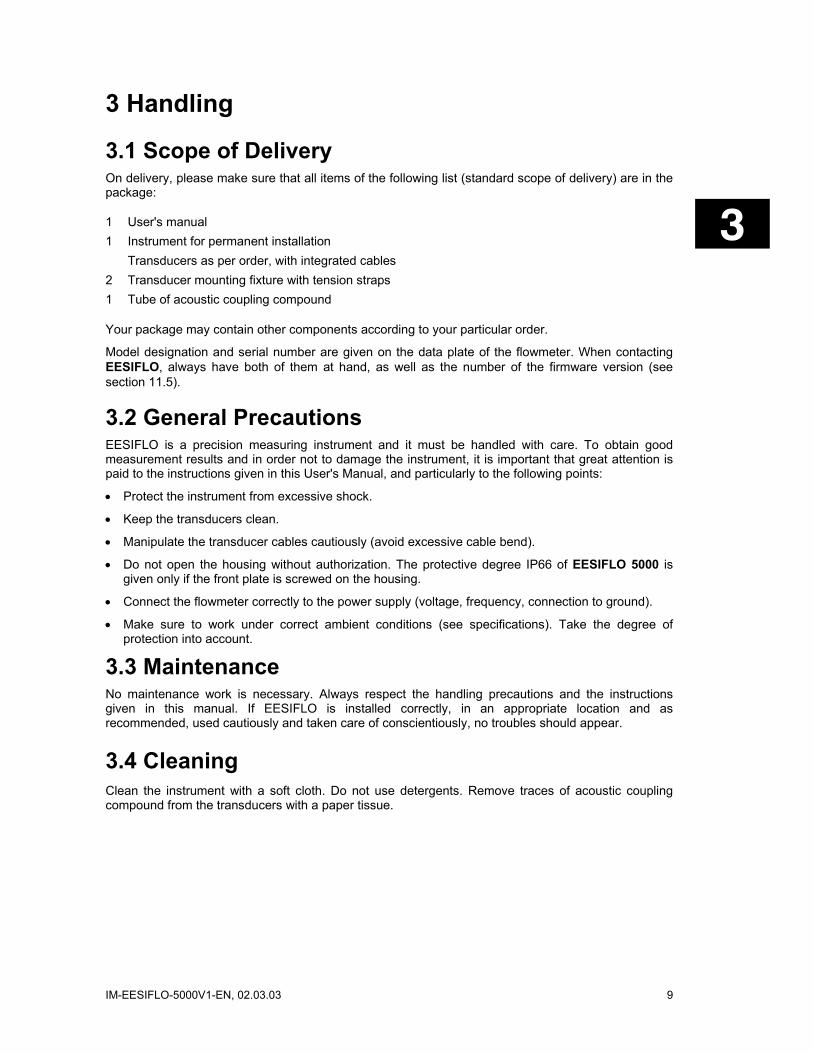
3.1 Scope of Delivery On delivery, please make sure that all items of the following list (standard scope of delivery) are in the package:
1 User's manual 1 Instrument for permanent installation Transducers as per order, with integrated cables 2 Transducer mounting fixture with tension straps 1 Tube of acoustic coupling compound
Your package may contain other components according to your particular order.
Model designation and serial number are given on the data plate of the flowmeter. When contacting EESIFLO, always have both of them at hand, as well as the number of the firmware version (see section 11.5).
3.2 General Precautions EESIFLO is a precision measuring instrument and it must be handled with care. To obtain good measurement results and in order not to damage the instrument, it is important that great attention is paid to the instructions given in this User's Manual, and particularly to the following points:
• Protect the instrument from excessive shock.
• Keep the transducers clean.
• Manipulate the transducer cables cautiously (avoid excessive cable bend).
• Do not open the housing without authorization. The protective degree IP66 of EESIFLO 5000 is given only if the front plate is screwed on the housing.
• Connect the flowmeter correctly to the power supply (voltage, frequency, connection to ground).
• Make sure to work under correct ambient conditions (see specifications). Take the degree of protection into account.
3.3 Maintenance No maintenance work is necessary. Always respect the handling precautions and the instructions given in this manual. If EESIFLO is installed correctly, in an appropriate location and as recommended, used cautiously and taken care of conscientiously, no troubles should appear.
3.4 Cleaning Clean the instrument with a soft cloth. Do not use detergents. Remove traces of acoustic coupling compound from the transducers with a paper tissue.

10 IM-EESIFLO-5000V1-EN, 02.03.03
IM-EESIFLO-5000V1-EN, 02.03.03 11
4 Installation of EESIFLO 5000 4.1 Location In a first step, select the measuring point according to the recommendations given in chapter 6, making sure that the temperature at the selected location is within the operating temperature range of the transducers (see technical data in appendix A).
Select afterward the location of the instrument within cable reach of the measuring point. Make sure that the temperature at the selected location is within the operating temperature range of the transmitter (see technical data in appendix A).
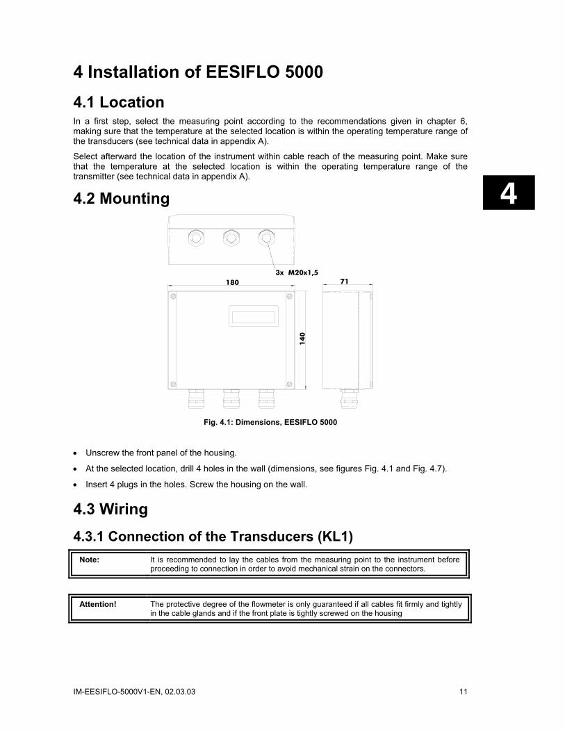
4.2 Mounting
180
14
0
3x M20x1,571
Fig. 4.1: Dimensions, EESIFLO 5000
• Unscrew the front panel of the housing.
• At the selected location, drill 4 holes in the wall (dimensions, see figures Fig. 4.1 and Fig. 4.7).
• Insert 4 plugs in the holes. Screw the housing on the wall.
4.3 Wiring 4.3.1 Connection of the Transducers (KL1)
Note: It is recommended to lay the cables from the measuring point to the instrument before proceeding to connection in order to avoid mechanical strain on the connectors.
Attention! The protective degree of the flowmeter is only guaranteed if all cables fit firmly and tightly in the cable glands and if the front plate is tightly screwed on the housing
12 IM-EESIFLO-5000V1-EN, 02.03.03
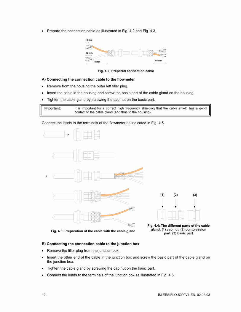
• Prepare the connection cable as illustrated in Fig. 4.2 and Fig. 4.3.
70 mm
20 mm
10 mm
40 mm
Fig. 4.2: Prepared connection cable
A) Connecting the connection cable to the flowmeter
• Remove from the housing the outer left filler plug.
• Insert the cable in the housing and screw the basic part of the cable gland on the housing.
• Tighten the cable gland by screwing the cap nut on the basic part.
Important: It is important for a correct high frequency shielding that the cable shield has a good contact to the cable gland (and thus to the housing).
Connect the leads to the terminals of the flowmeter as indicated in Fig. 4.5.
Fig. 4.3: Preparation of the cable with the cable gland
(1) (2) (3)
Fig. 4.4: The different parts of the cable
gland: (1) cap nut, (2) compression part, (3) basic part
B) Connecting the connection cable to the junction box
• Remove the filler plug from the junction box.
• Insert the other end of the cable in the junction box and screw the basic part of the cable gland on the junction box.
• Tighten the cable gland by screwing the cap nut on the basic part.
• Connect the leads to the terminals of the junction box as illustrated in Fig. 4.6.

IM-EESIFLO-5000V1-EN, 02.03.03 13
10 11 12 13 14
Fig. 4.5: Connection of the connection cable
43
5GN
6
VSV
RSR
Fig. 4.6: Terminals of the junction box
4.3.2 Connection of the Power Supply (KL3) • Connect the power cable with a M20 cable gland.
• Remove the outer right filler plug from the housing.
• Screw the rubber sleeve side of the basic part of the cable gland in the housing.
• Insert the leads in the housing through the basic part.
• Connect the leads to the terminals of the flowmeter as indicated in Table 4.1.
165ø 4,50
10 11 12 13 14 1 2 3 4 5 6 7 8 9 PE N(-) L(+)
EESIFLO 5000 SERIES FLOWMETER
www.eesiflo.com
BRK CLR ENTER
RESET
MARKEDOR WHITECABLE
TRANSDUCER PROCESS OUTPUTS
BINARYB1
INIT
POWER SUPPLYOBSERVE LABEL!
LINE FUSEPEBINARY
B2CURRENT
l1RS485
Fig. 4.7: Front plate of EESIFLO 5000
Table 4.1: Connection of the power supply
AC DC Terminal Connection Terminal Connection PE Earth PE Earth N(-) Neutral N(-) - DC L(+) Phase 100...230 VAC, 50/60 Hz L(+) + DC

14 IM-EESIFLO-5000V1-EN, 02.03.03
4.3.3 Connection of the Process Outputs (KL2) • Confection the output cables with a M20 cable gland.
• Remove the middle filler plug from the housing.
• Screw the rubber sleeve side of the basic part of the cable gland in the housing.
• Insert the leads in the housing through the basic part.
• Connect the leads to the terminals of the flowmeter as indicated in Table 4.2.
• Close the instrument by screwing the cover on the housing.
Attention! The protective degree of the flowmeter is only guaranteed if the cover is tightly screwed on the housing.
Table 4.2: Terminals for the connection of the process outputs
Terminal Connection 1, 2 Binary output B1 3, 4 Binary output B2 5, 6 Current loop I1 7 RS485 B- (optional) 8 RS485 A+ (optional) 9 RS485 shield (optional)
Table 4.3: Circuits of the process outputs
OUTPUT EESIFLO CIRCUIT Current loop
(active)
+ -
mA
+ -
RLOAD < 500 Ω
Binary output (Open-
Collector)
+
- UH
V
+
-
RC
UH = (5 to 24) V
RC[kΩ] = UH / Ic [mA]
Ic = (1 to 4) mA
Binary output (Reed-
Contact Relay)
a
b
UMAX = 24 V
IMAX = 150 mA
RS485 +A
B
(one 120Ω termination resistor)
(* RLOAD is the sum of all ohmic resistances in the circuit (resistance of the conductors, resistance of the amperemeter/voltmeter, etc.).)
IM-EESIFLO-5000V1-EN, 02.03.03 15
5 Getting Started
5.1 Instrument Start-Up
As soon as voltage is connected, a message will appear indicating which transducers were detected. The serial number of the instrument is then displayed for a second or two.
Note! No data can be entered while the serial number is displayed.
>PAR< mea opt sf Parameter
After initialization, the main menu appears in the actually selected language version
EESIFLO can be operated in the language of your choice (see section 5.6).
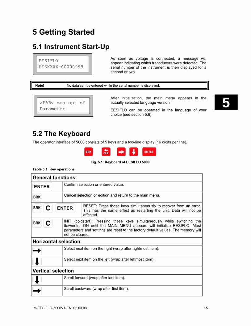
5.2 The Keyboard The operator interface of 5000 consists of 5 keys and a two-line display (16 digits per line).
BRK CLR ENTER
Fig. 5.1: Keyboard of EESIFLO 5000
Table 5.1: Key operations
General functions
ENTER
Confirm selection or entered value.
BRK
Cancel selection or edition and return to the main menu.
BRK
ENTER
RESET: Press these keys simultaneously to recover from an error. This has the same effect as restarting the unit. Data will not be affected.
BRK
INIT (coldstart): Pressing these keys simultaneously while switching the flowmeter ON until the MAIN MENU appears will initialize EESIFLO. Most parameters and settings are reset to the factory default values. The memory will not be cleared.
Horizontal selection
Select next item on the right (wrap after rightmost item).
Select next item on the left (wrap after leftmost item).
Vertical selection
Scroll forward (wrap after last item).
Scroll backward (wrap after first item).
EESIFLO EESXXXX-00000999

16 IM-EESIFLO-5000V1-EN, 02.03.03
Input of numerical values
Move cursor to the right.
Scroll digit above cursor.
Move cursor to the left. When the cursor is on the left margin: - an already edited value will be reset to previously saved value - an unedited value will be deleted. If the entered value is not valid, an error message will be displayed. Press any key and enter a correct value.
Input of text
Move cursor to the right (wrap after rightmost item).
Scroll through character set above cursor.
Reset all characters to last saved entry.
5.3 The Menus 5.3.1 The Main Menu
>PAR< mea opt sf Parameter
After switching on and initialization, the main menu appears on the first line of the display. The main menu has following entries: PAR (parameter), MEA (measuring), OPT (output options) and SF (special functions), corresponding to the four different program branches. The actually selected program branch is displayed in capital letters between arrows. The full name of the program branch is displayed on the second line.
Use keys and to select a program branch. Confirm your selection by pressing ENTER.
5.3.2 The Program Branches In the PARAMETER program branch, you can enter the parameters of the pipe and of the medium.
The MEASURING program branch leads you through the different steps of the measuring process.
In the OUTPUT OPTIONS branch, you can set all output relevant parameters, such as the physical quantity to be displayed during measurement and the measurement unit used for display for example.
The SPECIAL FUNCTION branch contains all functions that are not directly related with the basic measurement.

IM-EESIFLO-5000V1-EN, 02.03.03 17
Parameter For Channel A:
If a vertical arrow ( ) is displayed beside a menu option, this menu option contains a scroll list. This list is displayed on the second line.
Use the arrow keys and to scroll through the list, then confirm your selection by pressing ENTER.
Lining no >YES<
EESIFLO sometimes requests a selection on the second line. The actually selected option is displayed in capital letters and between arrows.
Use keys and to select one of the options, then confirm your selection by pressing ENTER.
R1=FUNC<typ mode Function: MAX
EESIFLO sometimes requests a horizontal selection between different menus on the upper line of the display. The selected menu is displayed in capital letters and between arrows. The actually selected options of the menus are displayed on the second line.
Use key to select one of the menus.
Use the arrow key to scroll through the selected menu.
Note: You can return to the main menu at any time by pressing key BRK.
Note: In this manual, all program entries and keys will appear in capital letters. Program entries are in typewriter characters ("PARAMETER"). Submenus are separated from the main menu entry by a backslash.
5.4 Command Execution during Measurement Commands that can be executed during measurement are shown on the upper line of the display. A command line always begins with a . Scroll on the upper line of the display with key until the needed command is displayed. Confirm your selection with ENTER. Depending on the instrument's settings, an authorization code might have to be entered. A list of the commands available during measurement is given in chapter 9.
5.5 HotCodes A HotCode is a specific key sequence which has to be entered to activate some settings.
SYSTEM settings Miscellaneous
To enter a HotCode, select the program branch SPECIAL FUNCTIONS\SYSTEM SETTINGS\MISCELLANEOUS.
Input a HOTCODE no >YES<
Select YES to enter a HotCode.

18 IM-EESIFLO-5000V1-EN, 02.03.03
Please input a HOTCODE: 000000
Enter the desired HotCode. Confirm with ENTER.
INVALID HOTCODE HOTCODE: 000000
If an invalid code is entered, an error message is displayed. Press any key to continue.
Input a HOTCODE no >YES<
Select YES to continue or NO to go back to the MISCELLANEOUS menu.
5.6 Selecting the Language EESIFLO can be operated in one of the languages listed below. The language can be selected with the following HotCodes. Depending on the specific technical characteristics of your instrument, some of the languages listed below might not be implemented.
Table 5.2: Language HotCodes
909031 Dutch 909045 Danish 909033 French 909047 Norwegian 909034 Spanish 909048 Polish 909042 Czech 909049 German 909044 English 909090 Turkish
When the last digit has been entered, the main menu appears in the selected language and EESIFLO greets accordingly. The selected language remain activated even after switching the unit OFF and ON again. A language selection can be made as often as required.
Note: After initialization of the instrument (BRK+ C while starting), the display will appear in the factory preset language version.
5.7 Interruption of Power Supply EESIFLO stores all actual measuring parameters in a non-volatile coldstart resistant EPROM as soon as the measurement begins. Any power failure interrupts the operation of EESIFLO. All input data, measuring parameters are preserved.
After return of the power supply, the serial number of the instrument appears on the display for a few seconds.
EESIFLO automatically continues the measurement which was interrupted by power failure. All selected output options are still active.
The flowmeter does not continue the measurement after return of the power supply if a coldstart was performed.
EESIFLO EESXXXX-00000999

IM-EESIFLO-5000V1-EN, 02.03.03 19
To perform a coldstart, press BRK, C and ENTER simultaneously, then let the BRK and C keys pressed and release only the ENTER key. The instrument will be restarted. Do not release BRK and C before the main menu is displayed.

20 IM-EESIFLO-5000V1-EN, 02.03.03

IM-EESIFLO-5000V1-EN, 02.03.03 21
6 Selection of the Measuring Point The correct selection of the measuring point is crucial for achieving reliable measurements and a high accuracy. Basically, measurement must take place on a pipe
• in which sound can propagate (see section 6.1)
• and in which a fully developed rotationally symmetrical flow profile is observed (see section 6.2).
The correct positioning of the transducers is an essential condition for error-free measurement. It guarantees that the sound signal will be received under optimal conditions and evaluated correctly. Because of the variety of applications and the different factors influencing measurement, there can be no standard solution for the positioning of the transducers. The correct position of the transducers will be influenced by the following factors:
• the diameter, material, lining, wall thickness and form of the pipe
• the medium flowing in the pipe
• the presence of gas bubbles in the medium.
Avoid the locations described in section 6.3.
Make sure that the temperature at the selected location is within the operating temperature range of the transducers (see Specifications in Appendix A).
Select afterward the location of the instrument within cable reach of the measuring point. Make sure that the temperature at the selected location is within the operating temperature range of the transmitter (see Specifications in Appendix A).
6.1 Acoustic Propagation Acoustic propagation can be assumed when pipe and medium do not attenuate the sound so strongly that the signals get completely absorbed before reaching the second transducer. How strong the sound attenuation is in a specific system depends on:
• the kinematic viscosity of the liquid,
• the proportion of gas bubbles and solid particles in the liquid,
• the presence of deposits on the inner pipe wall,
• the wall material.
Make sure that following conditions are respected at the measuring point:
• the pipe is always filled,
• no material deposits are building,
• no bubbles accumulate (even bubble-free liquids can form gas pockets at places where the liquid expands, e.g. especially behind pumps and where the cross-sectional area of the pipe extends considerably).
6.2 Undisturbed Flow Profile Many flow elements (elbows, slide valves, valves, pumps, T-sections, reducers, diffusers, etc.) distort the flow profile in their vicinity. The axi-symmetrical flow profile needed for correct measurement is no longer given. A careful selection of the measuring point makes it possible to reduce the impact of disturbance sources.
It is most important that the measuring point is chosen at a sufficient distance from any disturbance sources. Only then can it be assumed that the flow profile in the pipe is fully developed.
However, EESIFLO will give you meaningful measuring results even under non-ideal measuring conditions, with a liquid containing a certain proportion of gas bubbles or solid particles or if the
22 IM-EESIFLO-5000V1-EN, 02.03.03
recommended distances to disturbance sources can not be observed for practical reasons for example.
In the following examples, recommended straight inlet and outlet pipe lengths are given for different types of flow disturbance sources to assist you in selecting the correct measuring point.
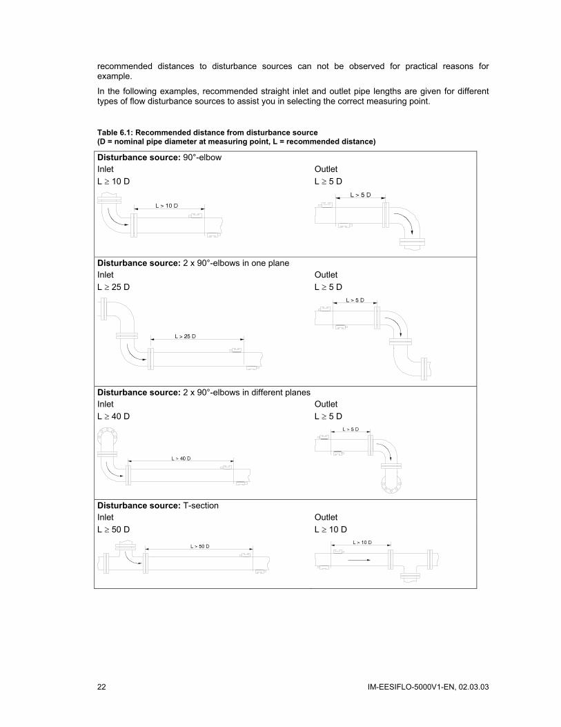
Table 6.1: Recommended distance from disturbance source (D = nominal pipe diameter at measuring point, L = recommended distance)
Disturbance source: 90°-elbow Inlet Outlet L ≥ 10 D L ≥ 5 D
Disturbance source: 2 x 90°-elbows in one plane Inlet Outlet L ≥ 25 D L ≥ 5 D
Disturbance source: 2 x 90°-elbows in different planes Inlet Outlet L ≥ 40 D L ≥ 5 D
Disturbance source: T-section Inlet Outlet L ≥ 50 D L ≥ 10 D

IM-EESIFLO-5000V1-EN, 02.03.03 23
Table 6.1 (cont'd)
Disturbance source: diffuser Inlet Outlet L ≥ 30 D L ≥ 5 D
Disturbance source: reducer Inlet Outlet L ≥ 10 D L ≥ 5 D
Disturbance source: valve Inlet Outlet L ≥ 40 D L ≥ 10 D
Disturbance source: pump Inlet L ≥ 50 D
6.3 Points to Avoid Try to avoid measuring locations:
• in the vicinity of deformations and defects of the pipe
• or in the vicinity of weldings.
Avoid locations where deposits are building in the pipe.
Respect the recommendations given in Table 6.2.
24 IM-EESIFLO-5000V1-EN, 02.03.03
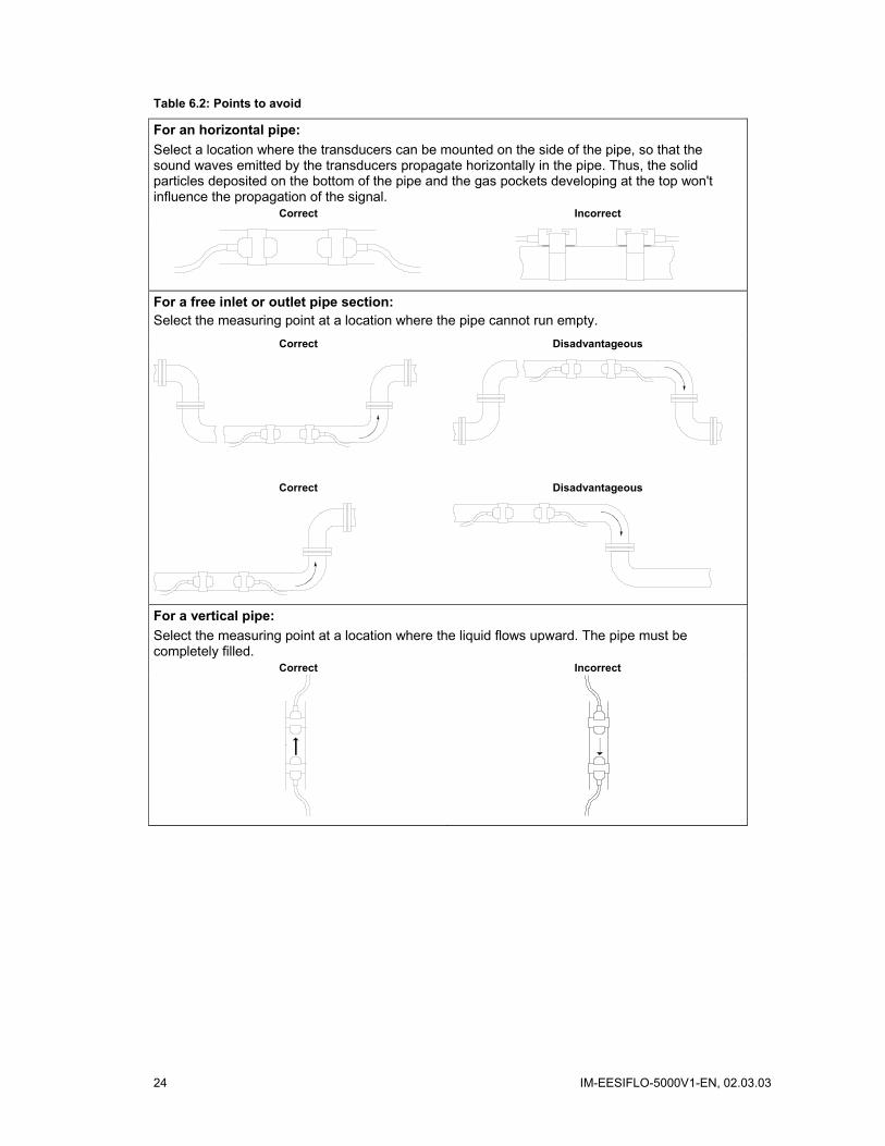
Table 6.2: Points to avoid
For an horizontal pipe: Select a location where the transducers can be mounted on the side of the pipe, so that the sound waves emitted by the transducers propagate horizontally in the pipe. Thus, the solid particles deposited on the bottom of the pipe and the gas pockets developing at the top won't influence the propagation of the signal.
Correct Incorrect
For a free inlet or outlet pipe section: Select the measuring point at a location where the pipe cannot run empty.
Correct Disadvantageous
Correct Disadvantageous
For a vertical pipe: Select the measuring point at a location where the liquid flows upward. The pipe must be completely filled.
Correct Incorrect
IM-EESIFLO-5000V1-EN, 02.03.03 25
7 Basic Measurement Once the measuring point has been selected (see chapter 6), the parameters of the pipe and of the medium can be entered. They can be modified at any time later by calling the program branch PARAMETER again.
7.1 Input of the Pipe's Parameter The parameters of the pipe now have to be entered for every measuring point.
Outer Diameter 1100.0 MAXIMUM
(Example)
The values that can be given to the parameters of pipe and medium are limited by the characteristics of transmitter and transducers. EESIFLO will warn you if the entered values do not respect these limits (MINIMUM and MAXIMUM plausibility check).
In this example, the entered outer diameter was too big. EESIFLO displays the maximal possible value for this parameter (1100.0 mm in the case of transducers of type Q and a pipe with a wall thickness of 50 mm).
Note: EESIFLO only accepts the parameters if the program branch PARAMETER has been gone through completely once.
The pipe parameters that you will now enter can be modified at any time later by calling the program branch PARAMETER again.
>PAR< mea opt sf Parameter
In the main menu, select the program branch PARAMETER and press ENTER.
7.1.1 Pipe Outer Diameter / Circumference
Outer Diameter 100.0 mm
Enter the outer diameter of the pipe.
Confirm your entry or the displayed value by pressing ENTER.
If the entered outer diameter is bigger than 4000 mm, measuring in reflection mode won't be possible (see section 7.4).
It is possible to change this menu in order to enter the pipe circumference instead of the diameter. This setting is coldstart resistant and can be made in the program branch SPECIAL FUNCTION (see section 11.2.1).
If the input of the pipe circumference is activated and you inadvertently enter a 0 (zero) in the OUTER DIAMETER display, EESIFLO will switch to the PIPE CIRCUMFER. display. If you do not wish to enter the pipe circumference, press BRK to return to the main menu and start the parameter input again.
26 IM-EESIFLO-5000V1-EN, 02.03.03
7.1.2 Wall Thickness
Wall Thickness 3.0 mm
Enter the pipe wall thickness. The range of possible values depends on the transducer specifications. Default value for this parameter is 3.0 mm.
Confirm by pressing ENTER.
Note: EESIFLO calculates the inner diameter (outer diameter - 2 x wall thickness) and checks if this value is within the specified inner diameter range for the transducers used. An error message is displayed if this is not the case. It is possible to modify the value of the minimal pipe inner diameter accepted by EESIFLO for a certain type of transducer. See section 9.7.
7.1.3 Pipe Material The pipe material now has to be selected in order to determine its sound velocity. The sound velocities of the materials of the selection list are already programmed in the instrument. When the pipe material is selected, EESIFLO sets the sound velocity automatically.
Pipe Material Carbon Steel
Select the pipe material in the pipe material selection list. If the correct material is not listed, select the entry OTHER MATERIAL.
Confirm by pressing ENTER.
Note: It is possible to select which materials are to be displayed in the material selection list. See section 10.1.
c-Material 3230.0 m/s
If you have selected OTHER MATERIAL, EESIFLO requests the entry of the sound velocity. Enter the sound velocity of the pipe material. Values between 600.0 and 6553.5 m/s are accepted. Confirm by pressing ENTER.
(Table B . 1 in Appendix B gives the sound velocity of some selected materials.)
Important! Enter here that sound velocity of the material (longitudinal velocity or transversal velocity) which is nearer to 2500 m/s.
7.1.4 Pipe Lining
Lining no >YES<
The instrument asks if the pipe is lined. If this is the case, select YES and confirm by pressing ENTER.
If you select NO, EESIFLO will ask for the next parameter (section 7.1.5).
Lining Bitumen
Select the lining material or the entry OTHER MATERIAL if the lining material is not listed.
Confirm by pressing ENTER.

IM-EESIFLO-5000V1-EN, 02.03.03 27
Note: It is possible to select which materials are to be displayed in the material selection list. See section 10.1.
c-Material 3200.0 m/s
If you have selected OTHER MATERIAL, EESIFLO requests the entry of the sound velocity. Enter the sound velocity for the liner material. Values between 600.0 and 6553.5 m/s are accepted.
Confirm by pressing ENTER.
(Table B . 3 in Appendix B gives the sound velocity of some selected materials.)
Liner Thickness 3.0 mm
Enter the pipe liner thickness. Default value for this parameter is 3.0 mm.
Confirm by pressing ENTER.
Note: EESIFLO checks the correlation between the entered outer diameter, the pipe wall and liner thickness. The inner diameter (outer diameter - 2 x wall thickness - 2 x liner thickness) should be within the specified inner diameter range for the transducers used. An error message is displayed if this is not the case.
7.1.5 Pipe Roughness The roughness of the inner pipe wall influences the flow profile of the liquid and is used for the calculation of the profile correction factor. In most cases, the pipe roughness cannot be exactly determined, but must be estimated. For your convenience, we have compiled a list of roughness factors for a number of materials, based on experience and measurements (Table B . 2 in Appendix B). The display ROUGHNESS requests the input of a value for the selected pipe or lining material.
Roughness 0.4 mm
Change the suggested value according to the condition of the inner pipe wall. Values between 0.0 mm and 5.0 mm are accepted. Default value is 0.1 mm.
Confirm by pressing ENTER.
7.2 Input of the Medium's Parameters After you have finished entering the pipe parameters, EESIFLO asks for the medium parameters.
The medium parameters required for measurement are:
• the minimum and maximum sound velocity for the medium, • the kinematic viscosity of the medium, • the density of the medium (only if the output option MASS FLOW is activated), • the temperature of the medium.
Table B . 3 in Appendix B gives an overview of the pre-programmed parameters for common media.
Medium Water
Select the medium or the entry OTHER MEDIUM if the medium you want to measure is not listed.
Confirm by pressing ENTER.
If the medium has been selected, EESIFLO jumps straight to the display for entering the medium temperature (section 7.2.4). If you have selected OTHER MEDIUM, EESIFLO requests the entry of the minimal and maximal sound velocity, the kinematic viscosity and the density of the medium.

28 IM-EESIFLO-5000V1-EN, 02.03.03
Note: It is possible to select which media are to be displayed in the medium selection list. See section 10.1.
7.2.1 Sound Velocity EESIFLO uses the sound velocity of the medium for the calculation of the distance between the transducers at the beginning of the measurement. However, the sound velocity does not influence the measuring result directly. Often, the accurate value of the sound velocity for a given medium is un-known. A range of possible values for the sound velocity must therefore be entered.
c-Medium MIN 1400.0 m/s
Enter the minimum and maximum values of the sound velocity for the medium you want to measure (in m/s).
Values between 800.0 m/s and 3500.0 m/s are accepted.
Confirm your entries by pressing ENTER.
7.2.2 Kinematic Viscosity The kinematic viscosity influences the flow profile of the liquid. EESIFLO uses the value of the kinematic viscosity as well as other parameters for the profile correction.
Kinem.Viscosity 1.00 mm2/s
Enter the kinematic viscosity of the medium. Values between 0.01 and 30,000.00 mm2/s are accepted.
Confirm by pressing ENTER.
7.2.3 Density EESIFLO now asks for the density of the medium. This value is needed for calculating the mass flow rate (= volume flow rate multiplied with the entered density).
Note: If you are not interested in measuring the mass flow rate, just confirm the displayed value by pressing ENTER. This will not influence your results.
Density 1.00 g/cm3
Enter the density of the medium. Values between 0.10 g/cm3 and 20.00 g/cm3 are accepted.
Confirm by pressing ENTER.
7.2.4 Medium Temperature EESIFLO needs the medium temperature for the calculation of the distance between the transducers (distance suggested at the beginning of measurement) and for correcting the sound velocity and the viscosity which both depend on temperature.
Medium Temperat. 20 C
Enter the medium temperature. The value must be within the operating range of the transducer. The default value is 20°C.
Confirm by pressing ENTER.
Note: The range of possible medium temperature depends on the operating range of the selected transducers.
IM-EESIFLO-5000V1-EN, 02.03.03 29
7.3 Other Parameters 7.3.1 Transducer Parameters If no transducers are connected, if you have connected special transducers which EESIFLO cannot automatically recognize, or if the connected transducers are defective, following display will appear at the end of parameter input:
TransducerType Standard
Select STANDARD to work with standard transducer parameters or SPECIAL VERSION to edit the transducer parameters (manufacturer's data must be available).
Confirm by pressing ENTER.
Attention! EESIFLO cannot guarantee for the precision of values obtained when working with standard parameters. Measurement might be impossible.
Transd. Data 1 35.99
If you have selected SPECIAL VERSION, EESIFLO will ask for the transducer data. Enter the value of the 6 transducer parameters as given by the manufacturer, confirming each entry by pressing ENTER.
7.3.2 Cable length
Additional cable 65.0 m
EESIFLO then asks for the length of additional transducer cable used (not the total length of the transducer cable!). Enter the additional cable length and confirm by pressing ENTER.
7.4 Selection of the Sound Path Factor
par >MEA< opt sf Measuring
In the main menu, select the program branch MEASURING, then press ENTER.
par >MEA< opt sf NO DATA !
If this error message appears, no complete parameter set exists. Return to the program branch PARAMETER and enter the missing parameters.
EESIFLO now asks for the sound path factor, which is the number of transits of the ultrasonic waves through the medium in the pipe.
A sound path factor of "0" (zero) is nonsense in terms of physics.
An odd number of transits (diagonal mode) requires mounting of the transducers on opposite sides of the pipe (see illustration below).
An even number of transits (reflection mode) requires mounting of the transducers on the same side of the pipe (see illustration below).
30 IM-EESIFLO-5000V1-EN, 02.03.03
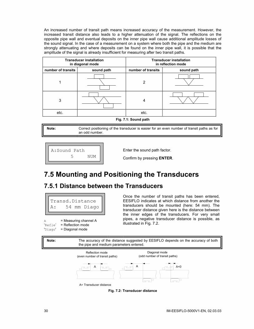
An increased number of transit path means increased accuracy of the measurement. However, the increased transit distance also leads to a higher attenuation of the signal. The reflections on the opposite pipe wall and eventual deposits on the inner pipe wall cause additional amplitude losses of the sound signal. In the case of a measurement on a system where both the pipe and the medium are strongly attenuating and where deposits can be found on the inner pipe wall, it is possible that the amplitude of the signal is already insufficient for measuring after two transit paths.
Transducer installation in diagonal mode
Transducer installation in reflection mode
number of transits sound path number of transits sound path
1
2
3
4
etc. etc.
Fig. 7.1: Sound path
Note: Correct positioning of the transducer is easier for an even number of transit paths as for an odd number.
A:Sound Path 5 NUM
Enter the sound path factor.
Confirm by pressing ENTER.
7.5 Mounting and Positioning the Transducers 7.5.1 Distance between the Transducers
Transd.Distance A: 54 mm Diago
A = Measuring channel A ‘Refle’ = Reflection mode 'Diago' = Diagonal mode
Once the number of transit paths has been entered, EESIFLO indicates at which distance from another the transducers should be mounted (here: 54 mm). The transducer distance given here is the distance between the inner edges of the transducers. For very small pipes, a negative transducer distance is possible, as illustrated in Fig. 7.2.
Note: The accuracy of the distance suggested by EESIFLO depends on the accuracy of both the pipe and medium parameters entered.
A A A<0
A= Transducer distance
Reflection mode(even number of transit paths)
Diagonal mode(odd number of transit paths)
Fig. 7.2: Transducer distance
IM-EESIFLO-5000V1-EN, 02.03.03 31
7.5.2 Mounting the Transducers
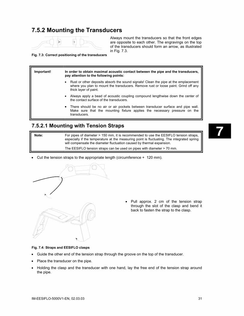
Fig. 7.3: Correct positioning of the transducers
Always mount the transducers so that the front edges are opposite to each other. The engravings on the top of the transducers should form an arrow, as illustrated in Fig. 7.3.
Important! In order to obtain maximal acoustic contact between the pipe and the transducers, pay attention to the following points:
• Rust or other deposits absorb the sound signals! Clean the pipe at the emplacement where you plan to mount the transducers. Remove rust or loose paint. Grind off any thick layer of paint.
• Always apply a bead of acoustic coupling compound lengthwise down the center of the contact surface of the transducers.
• There should be no air or air pockets between transducer surface and pipe wall. Make sure that the mounting fixture applies the necessary pressure on the transducers.
7.5.2.1 Mounting with Tension Straps Note: For pipes of diameter > 150 mm, it is recommended to use the EESIFLO tension straps,
especially if the temperature at the measuring point is fluctuating. The integrated spring will compensate the diameter fluctuation caused by thermal expansion. The EESIFLO tension straps can be used on pipes with diameter > 70 mm.
• Cut the tension straps to the appropriate length (circumference + 120 mm).
Fig. 7.4: Straps and EESIFLO clasps
• Pull approx. 2 cm of the tension strap through the slot of the clasp and bend it back to fasten the strap to the clasp.
• Guide the other end of the tension strap through the groove on the top of the transducer.
• Place the transducer on the pipe.
• Holding the clasp and the transducer with one hand, lay the free end of the tension strap around the pipe.
32 IM-EESIFLO-5000V1-EN, 02.03.03
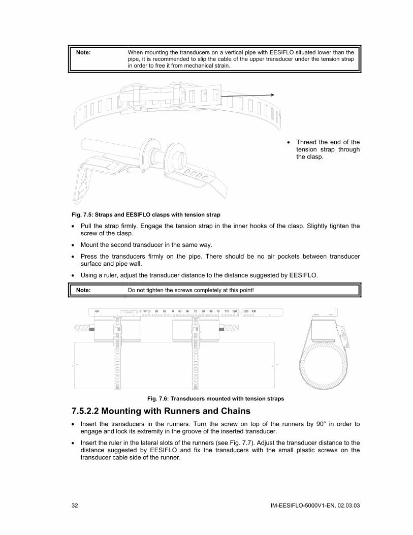
Note: When mounting the transducers on a vertical pipe with EESIFLO situated lower than the pipe, it is recommended to slip the cable of the upper transducer under the tension strap in order to free it from mechanical strain.
Fig. 7.5: Straps and EESIFLO clasps with tension strap
• Thread the end of the tension strap through the clasp.
• Pull the strap firmly. Engage the tension strap in the inner hooks of the clasp. Slightly tighten the screw of the clasp.
• Mount the second transducer in the same way.
• Press the transducers firmly on the pipe. There should be no air pockets between transducer surface and pipe wall.
• Using a ruler, adjust the transducer distance to the distance suggested by EESIFLO.
Note: Do not tighten the screws completely at this point!
-60 0 0302010mm 80706050 110 1201090 330320
Fig. 7.6: Transducers mounted with tension straps
7.5.2.2 Mounting with Runners and Chains • Insert the transducers in the runners. Turn the screw on top of the runners by 90° in order to
engage and lock its extremity in the groove of the inserted transducer.
• Insert the ruler in the lateral slots of the runners (see Fig. 7.7). Adjust the transducer distance to the distance suggested by EESIFLO and fix the transducers with the small plastic screws on the transducer cable side of the runner.

IM-EESIFLO-5000V1-EN, 02.03.03 33
-60 0 0302010mm 80706050 110 1201090 330320
Fig. 7.7: Transducers mounted with runners and chains
• Place the runners/ruler assembly on the pipe at the measuring point.
• Take the spring end of one of the ball chains, insert the last ball in the slot on the top of one of the runner.
• Lay the chain around the pipe (if the chain is not long enough, refer to section 7.5.2.3).
Note: When mounting the transducers on a vertical pipe with EESIFLO situated lower than the pipe, it is recommended to slip the cable of the upper transducer under the tension strap in order to free it from mechanical strain.
• Pull the chain firmly and insert it in the second slot on the top of the runner.
• Fix the other transducer in the same way.
7.5.2.3 Extension of the Ball Chain To extend the chain, insert the last ball of the spring end of the extension in the fastening clip of the ball chain.
The spare fastening clips supplied with the chain can be used to repair a broken chain.
7.5.3 Positioning the Transducers
Transd.Distance A: 54 mm !
When the transducers are mounted, confirm the transducer distance by pressing ENTER. The positioning procedure of the transducers is started.
S= A: < > =54 mm!
A bar graph ("S=") informs you of the amplitude of the received signal.
Adjust the transducers by moving them slightly in order to obtain a maximal length of the bar graph.
S= Q=
Press key to switch on the lower line between the display of the transducer distance and the bar graph of the quality of the signal ("Q="). If the signal is not sufficient for measurement, UNDEF is displayed.
34 IM-EESIFLO-5000V1-EN, 02.03.03
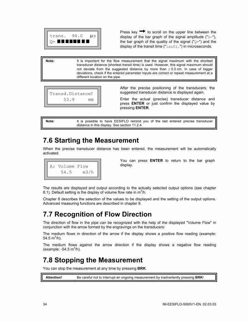
trans. 94.0 µs Q=
Press key to scroll on the upper line between the display of the bar graph of the signal amplitude ("S="), the bar graph of the quality of the signal ("Q=") and the display of the transit time ("laufz.") in microseconds.
Note: It is important for the flow measurement that the signal maximum with the shortest transducer distance (shortest transit time) is used. However, this signal maximum should not deviate from the suggested distance by more than ± 0.5 cm. In case of bigger deviations, check if the entered parameter inputs are correct or repeat measurement at a different location on the pipe.
Transd.Distance? 53.9 mm
After the precise positioning of the transducers, the suggested transducer distance is displayed again.
Enter the actual (precise) transducer distance and press ENTER or just confirm the displayed value by pressing ENTER.
Note: It is possible to have EESIFLO remind you of the last entered precise transducer distance in this display. See section 11.2.4.
7.6 Starting the Measurement When the precise transducer distance has been entered, the measurement will be automatically activated.
A: Volume Flow 54.5 m3/h
You can press ENTER to return to the bar graph display.
The results are displayed and output according to the actually selected output options (see chapter 8.1). Default setting is the display of volume flow rate in m3/h.
Chapter 8 describes the selection of the values to be displayed and the setting of the output options. Advanced measuring functions are described in chapter 9.
7.7 Recognition of Flow Direction The direction of flow in the pipe can be recognized with the help of the displayed "Volume Flow" in conjunction with the arrow formed by the engravings on the transducers:
The medium flows in direction of the arrow if the display shows a positive flow reading (example: 54.5 m3/h).
The medium flows against the arrow direction if the display shows a negative flow reading (example: -54.5 m3/h).
7.8 Stopping the Measurement You can stop the measurement at any time by pressing BRK.
Attention! Be careful not to interrupt an ongoing measurement by inadvertently pressing BRK!
IM-EESIFLO-5000V1-EN, 02.03.03 35
8 Displaying the Measured Values The physical quantity to be measured and used for storage and output can be set in the OUTPUT OPTIONS program branch as described in section 8.1. Default display setting is that the designation of the quantity of measurement selected in the OUTPUT OPTIONS is displayed on the first line and its value on the second line. It is possible to temporary adapt the display to your requirements by selecting which quantity should be shown on the first and second line of the display (see section 8.2).
8.1 Selection of the Physical Quantity and of the Unit of Measurement
EESIFLO can measure the following quantities:
• flow velocity
• volume flow rate
• mass flow rate
EESIFLO measures the flow velocity directly. The volume flow is calculated by multiplying the flow velocity with the cross-sectional area of the pipe, the mass flow by multiplying the volume flow with the density of the medium.
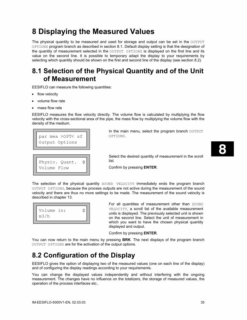
par mea >OPT< sf Output Options
In the main menu, select the program branch OUTPUT OPTIONS.
Physic. Quant. Volume Flow
Select the desired quantity of measurement in the scroll list.
Confirm by pressing ENTER.
The selection of the physical quantity SOUND VELOCITY immediately ends the program branch OUTPUT OPTIONS, because the process outputs are not active during the measurement of the sound velocity and there are thus no more settings to be made. The measurement of the sound velocity is described in chapter 13.
Volume in: m3/h
For all quantities of measurement other than SOUND VELOCITY, a scroll list of the available measurement units is displayed. The previously selected unit is shown on the second line. Select the unit of measurement in which you want to have the chosen physical quantity displayed and output.
Confirm by pressing ENTER.
You can now return to the main menu by pressing BRK. The next displays of the program branch OUTPUT OPTIONS are for the activation of the output options.
8.2 Configuration of the Display EESIFLO gives the option of displaying two of the measured values (one on each line of the display) and of configuring the display readings according to your requirements.
You can change the displayed values independently and without interfering with the ongoing measurement. The changes have no influence on the totalizers, the storage of measured values, the operation of the process interfaces etc..

36 IM-EESIFLO-5000V1-EN, 02.03.03
Following information can be displayed on the first line of the display:
• Designation of the quantity of measurement actually being measured and recorded
• Totalizer values (if activated)
• the date and time at which the memory will be full
• the measuring mode
• the transducer distance (see section 8.3)
• the calculation function if activated
• the time remaining until the automatic stop of a programmed measurement
• the state of the alarms if any alarm outputs are activated and the display of the alarms' state is enabled (see section 14.6.6).
Following information can be displayed on the second line in addition to the selected quantity of measurement:
• Flow velocity
• Mass flow rate
• Volume flow rate
Use key to scroll through the different displays of the first line while measurement is going on.
Use key to scroll through the different displays of the second line while measurement is going on.
A: Volume Flow * 2.47 m/s
The asterisk "*" indicates that the displayed value (here: the flow velocity) is not the selected quantity of measurement (here: the volume flow).
8.3 Transducer Distance
L=(51.2) 50.8 mm 54.5 m3/h
During measurement, it is possible to scroll to the display of the transducer distance by pressing the key
.
The actual optimal transducer distance is given first in parenthesis (here: 51.2 mm), then the entered transducer distance (here: 50.8 mm). The optimal transducer distance might change during measurement due to temperature fluctuations for example. An eventual mispositioning of the transducers (here: -0.4 mm) will be internally compensated by EESIFLO.
Attention! Never change the transducer distance during measurement!

IM-EESIFLO-5000V1-EN, 02.03.03 37
9 Advanced Measuring Functions
9.1 Command Execution during Measurement Commands that can be executed during measurement are shown on the upper line of the display. A command line always begins with a .
Scroll on the upper line of the display with key until the needed command is displayed. Confirm your selection with ENTER. Depending on the instrument's settings, an authorization code might have to be entered. The commands available are the following:
Table 9.1: Commands that can be executed during measurement
COMMAND ACTION ADJUST SENSORS
S= A: < > =54 mm!
Switch to the sensor positioning mode. If a program code is activated, measuring will be automatically continued 8 seconds after the last keyboard action.
CLEAR TOTALIZER A: 32.5 m3 54.5 m3/h
All totalizer values will be reset to zero.
BREAK MEASURE Stop measuring and return to main menu. If a program code is activated, you have to enter the 6 digit BREAK-CODE first.
9.2 The Damping Factor Each measured value displayed by the instrument is actually the average of the measured values of the last x seconds, where x is the damping factor. A damping factor of 1 s means that the measured values are not averaged, since the measuring rate is of approx 1 value per second. The default value is 10 s. This is appropriate for normal flow conditions. Strongly fluctuating readings caused by high flow dynamics require a larger damping factor.
Select the OUTPUT OPTIONS program branch. Work yourself through the scroll list, confirming the already selected options by pressing ENTER, until you reach the DAMPING option.
Damping 30 s
Enter the damping factor. Values between 1 s and 100 s are accepted.
Confirm by pressing ENTER.
You can now return to the main menu by pressing BRK.
9.3 Flow Totalizers EESIFLO totalizes the volume or the mass of medium passing through the pipe at the measuring point.
• There are two built-in flow totalizers, one for totalizing in positive flow direction, the other for totalizing in negative flow direction.
38 IM-EESIFLO-5000V1-EN, 02.03.03
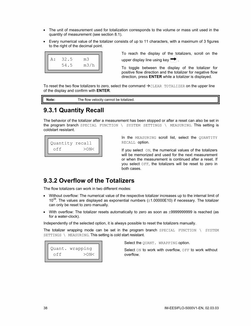
• The unit of measurement used for totalization corresponds to the volume or mass unit used in the quantity of measurement (see section 8.1).
• Every numerical value of the totalizer consists of up to 11 characters, with a maximum of 3 figures to the right of the decimal point.
A: 32.5 m3 54.5 m3/h
To reach the display of the totalizers, scroll on the
upper display line using key .
To toggle between the display of the totalizer for positive flow direction and the totalizer for negative flow direction, press ENTER while a totalizer is displayed.
To reset the two flow totalizers to zero, select the command CLEAR TOTALIZER on the upper line of the display and confirm with ENTER.
Note: The flow velocity cannot be totalized.
9.3.1 Quantity Recall The behavior of the totalizer after a measurement has been stopped or after a reset can also be set in the program branch SPECIAL FUNCTION \ SYSTEM SETTINGS \ MEASURING. This setting is coldstart resistant.
Quantity recall off >ON<
In the MEASURING scroll list, select the QUANTITY RECALL option.
If you select ON, the numerical values of the totalizers will be memorized and used for the next measurement or when the measurement is continued after a reset. If you select OFF, the totalizers will be reset to zero in both cases.
9.3.2 Overflow of the Totalizers The flow totalizers can work in two different modes:
• Without overflow: The numerical value of the respective totalizer increases up to the internal limit of 1038. The values are displayed as exponential numbers (±1.00000E10) if necessary. The totalizer can only be reset to zero manually.
• With overflow: The totalizer resets automatically to zero as soon as ±9999999999 is reached (as for a water-clock).
Independently of the selected option, it is always possible to reset the totalizers manually.
The totalizer wrapping mode can be set in the program branch SPECIAL FUNCTION \ SYSTEM SETTINGS \ MEASURING. This setting is cold start resistant.
Quant. wrapping off >ON<
Select the QUANT. WRAPPING option.
Select ON to work with overflow, OFF to work without overflow.

IM-EESIFLO-5000V1-EN, 02.03.03 39
Note: • The output of sum of both totalizer (the throughput ‘ΣQ’) via a process output will not be valid after the first overflow (wrapping) of one of the respective totalizers.
• To signalize the overflow of a totalizer, activate an alarm output with the switching condition QUANTITY and the type HOLD.
9.4 Upper Limit for Flow Velocities A single outlier caused by heavily disturbed surroundings can appear in flow measured values. Such a measured value will, when not ignored, affect all derived quantities, which will then be unsuitable for integration (pulse outputs, e.g.).
It is possible for the instrument to ignore all measured flow velocities bigger than a preset upper limit and mark them as outlier ("invalid measured value"). This upper limit for the flow velocity can be set in the program branch SPECIAL FUNCTION \ SYSTEM SETTINGS \ MEASURING. This setting is cold start resistant.
Velocity limit 0.0 m/s
In the program branch SPECIAL FUNCTION \SYSTEM SETTINGS \ MEASURING, select the VELOCITY LIMIT option. Enter the upper velocity limit. Values between 0.1 and 25.5 m/s are accepted. Entering "0" switches off the test for outliers.
Confirm by pressing ENTER.
When the test is activated (velocity limit > 0.0 m/s), every measured flow velocity will be compared with the entered upper velocity limit. If the flow velocity is bigger than the limit:
• The flow velocity is marked as "invalid"; the measuring quantity cannot be determined..
• The display shows a ‘!’ behind the unit of measurement. (In case of a ‘normal’ error, a ‘?’ appears.)
Attention! If the defined velocity limit is too small, measurement might be impossible - most measured values are declared invalid.
9.5 Cut-off Flow The cut-off flow function automatically sets all measured flow velocities falling below a certain value to zero. All values derived from this flow velocity are equally set to zero. The cut-off can depend on the sign identifying the direction of flow or not. The default cut-off value is 5 cm/s. The largest cut-off value which can be set is 12.7 cm/s.
The cut-off value can be set in the program branch SPECIAL FUNCTION \ SYSTEM SETTINGS \ MEASURING. This setting is cold start resistant.
Cut-off Flow absolute >SIGN<
If you select ABSOLUTE, the user defined cut-off value will not depend on the sign identifying the direction of flow. There is only one limit to be set. The absolute value of the measured value will be compared with the cut-off value.
If you select SIGN, the user defined cut-off value will depend on the sign identifying the direction of flow. Two independent limits can be entered for positive and negative flow velocities.
40 IM-EESIFLO-5000V1-EN, 02.03.03
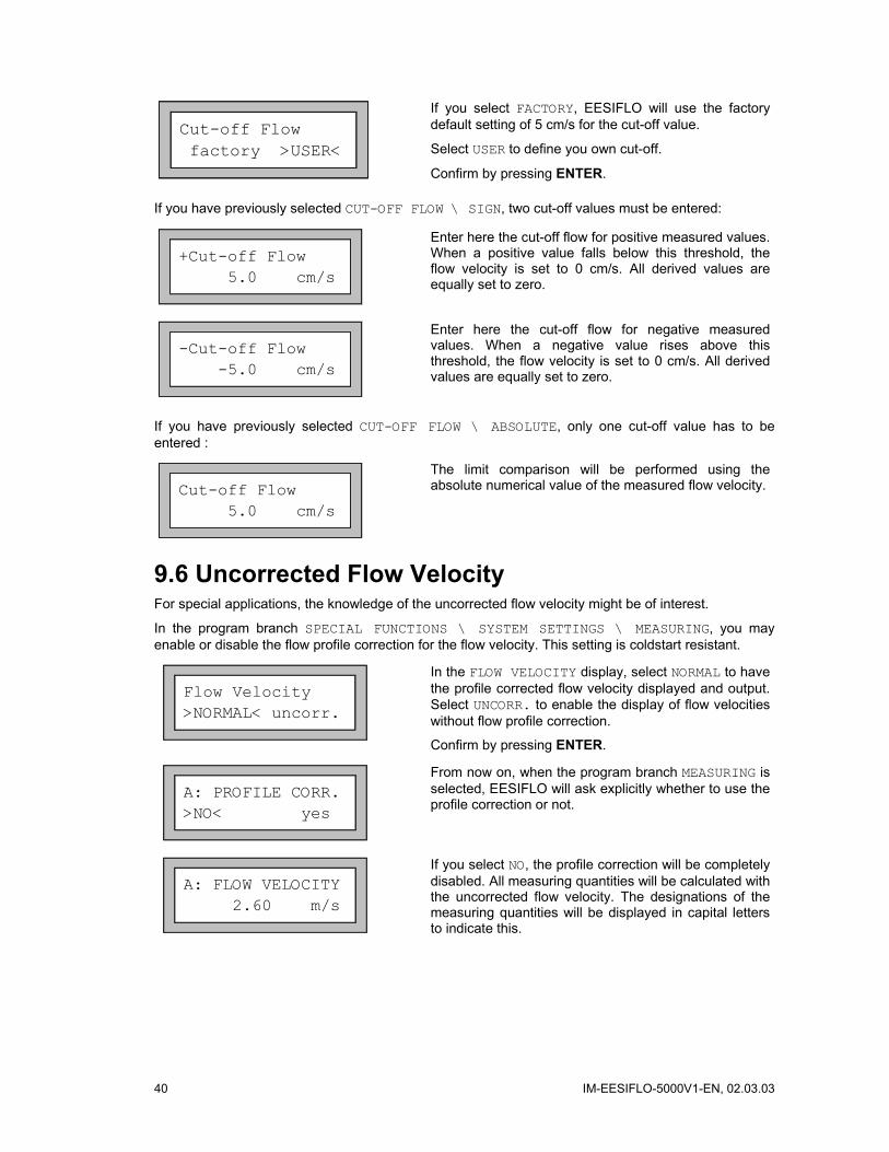
Cut-off Flow factory >USER<
If you select FACTORY, EESIFLO will use the factory default setting of 5 cm/s for the cut-off value.
Select USER to define you own cut-off.
Confirm by pressing ENTER.
If you have previously selected CUT-OFF FLOW \ SIGN, two cut-off values must be entered:
+Cut-off Flow 5.0 cm/s
Enter here the cut-off flow for positive measured values. When a positive value falls below this threshold, the flow velocity is set to 0 cm/s. All derived values are equally set to zero.
-Cut-off Flow -5.0 cm/s
Enter here the cut-off flow for negative measured values. When a negative value rises above this threshold, the flow velocity is set to 0 cm/s. All derived values are equally set to zero.
If you have previously selected CUT-OFF FLOW \ ABSOLUTE, only one cut-off value has to be entered :
Cut-off Flow 5.0 cm/s
The limit comparison will be performed using the absolute numerical value of the measured flow velocity.
9.6 Uncorrected Flow Velocity For special applications, the knowledge of the uncorrected flow velocity might be of interest.
In the program branch SPECIAL FUNCTIONS \ SYSTEM SETTINGS \ MEASURING, you may enable or disable the flow profile correction for the flow velocity. This setting is coldstart resistant.
Flow Velocity >NORMAL< uncorr.
In the FLOW VELOCITY display, select NORMAL to have the profile corrected flow velocity displayed and output. Select UNCORR. to enable the display of flow velocities without flow profile correction.
Confirm by pressing ENTER.
A: PROFILE CORR. >NO< yes
From now on, when the program branch MEASURING is selected, EESIFLO will ask explicitly whether to use the profile correction or not.
A: FLOW VELOCITY 2.60 m/s
If you select NO, the profile correction will be completely disabled. All measuring quantities will be calculated with the uncorrected flow velocity. The designations of the measuring quantities will be displayed in capital letters to indicate this.
IM-EESIFLO-5000V1-EN, 02.03.03 41
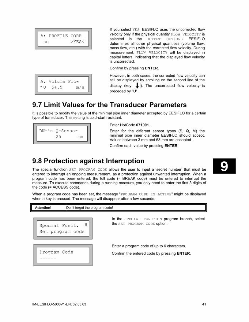
A: PROFILE CORR. no >YES<
If you select YES, EESIFLO uses the uncorrected flow velocity only if the physical quantity FLOW VELOCITY is selected in the OUTPUT OPTIONS. EESIFLO determines all other physical quantities (volume flow, mass flow, etc.) with the corrected flow velocity. During measurement, FLOW VELOCITY will be displayed in capital letters, indicating that the displayed flow velocity is uncorrected.
Confirm by pressing ENTER.
A: Volume Flow *U 54.5 m/s
However, in both cases, the corrected flow velocity can still be displayed by scrolling on the second line of the display (key ). The uncorrected flow velocity is preceded by "U".
9.7 Limit Values for the Transducer Parameters It is possible to modify the value of the minimal pipe inner diameter accepted by EESIFLO for a certain type of transducer. This setting is cold-start resistant.
DNmin Q-Sensor 25 mm
Enter HotCode 071001. Enter for the different sensor types (S, Q, M) the minimal pipe inner diameter EESIFLO should accept. Values between 3 mm and 63 mm are accepted. Confirm each value by pressing ENTER.
9.8 Protection against Interruption The special function SET PROGRAM CODE allows the user to input a ‘secret number’ that must be entered to interrupt an ongoing measurement, as a protection against unwanted interruption. When a program code has been entered, the full code (= BREAK code) must be entered to interrupt the measure. To execute commands during a running measure, you only need to enter the first 3 digits of the code (= ACCESS code).
When a program code has been set, the message "PROGRAM CODE IS ACTIVE" might be displayed when a key is pressed. The message will disappear after a few seconds.
Attention! Don't forget the program code!
Special Funct. Set program code
In the SPECIAL FUNCTION program branch, select the SET PROGRAM CODE option.
Program Code ------
Enter a program code of up to 6 characters.
Confirm the entered code by pressing ENTER.

42 IM-EESIFLO-5000V1-EN, 02.03.03
INVALID CODE ! 909049
This error message warns you if you have entered a reserved number (a HotCode for language selection for example).
The previous program code, as far as existing, is valid until you enter another code correctly or deactivate the program code.
9.8.1 Interruption of Measurement When a program code has been set, ADM 8027 will ask for it when you select a command line or press key BRK during measurement.
INPUT BREAK_CODE CODE: 000000
INP. ACCESS CODE CODE: 000000
Enter the program code (ACCESS or BREAK code depending on what you want to do) using keys
and .
With key C, you can cancel the code input and return to the measure.
The program code "000000" is always displayed first in the program code input display. If you enter a program code beginning with "000", you will have a nearly immediate access to measure related commands.
INPUT BREAK_CODE INVALID CODE
If the entered code is not the current program code, an error message is displayed for a few seconds. If the entered code is valid, the command will be executed or the measurement will be interrupted.
9.8.2 Deactivating a Program Code
Program Code ------
A program code can be canceled by entering "------" in the PROGRAM CODE display (SPECIAL FUNCTION \SET PROGRAM CODE). Confirm with ENTER.
If you enter "-" less than six times, EESIFLO reads your entry as a new program code!
IM-EESIFLO-5000V1-EN, 02.03.03 43
10 Libraries The internal data bank of the instrument contains the properties of more than 20 different materials (pipe material, lining) and more than 40 different media. It is possible to select the materials and fluids displayed in the selection lists of the program branch PARAMETER (pipe material, lining, medium). You can thus adapt the list to your specific measuring tasks and the shorter selection lists make your work more efficient (see section 10.1).
An integrated coefficient storage (user area) allows you to define new materials and media. If necessary, the properties of these new materials and media can be defined as temperature-depen-dent or pressure-dependent polynomials. The coefficient storage can be partitioned as you like. For more information about user materials and media, see section 10.2.
10.1 Editing the Selection Lists The procedures for the edition of the material and of the media selection list are the same. We describe here the edition of the material selection list.
Note: User materials and media are always displayed in the selection lists of the program branch PARAMETER.
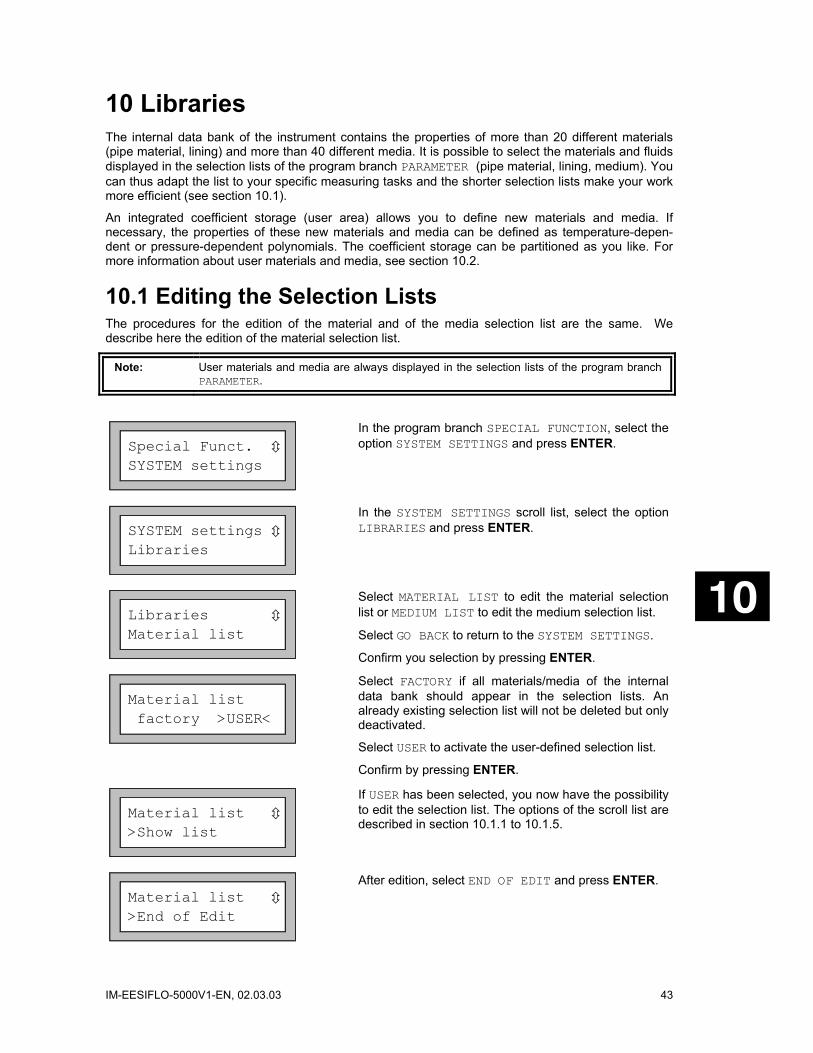
Special Funct. SYSTEM settings
In the program branch SPECIAL FUNCTION, select the option SYSTEM SETTINGS and press ENTER.
SYSTEM settings Libraries
In the SYSTEM SETTINGS scroll list, select the option LIBRARIES and press ENTER.
Libraries Material list
Select MATERIAL LIST to edit the material selection list or MEDIUM LIST to edit the medium selection list.
Select GO BACK to return to the SYSTEM SETTINGS.
Confirm you selection by pressing ENTER.
Material list factory >USER<
Select FACTORY if all materials/media of the internal data bank should appear in the selection lists. An already existing selection list will not be deleted but only deactivated.
Select USER to activate the user-defined selection list.
Confirm by pressing ENTER.
Material list >Show list
If USER has been selected, you now have the possibility to edit the selection list. The options of the scroll list are described in section 10.1.1 to 10.1.5.
Material list >End of Edit
After edition, select END OF EDIT and press ENTER.

44 IM-EESIFLO-5000V1-EN, 02.03.03
Save list ? no >YES<
Select YES to save all changes made in the selection list or NO to leave the edition menu without saving.
Confirm by pressing ENTER.
Note: If you quit the edition menu with BRK before saving, all changes will be lost.
10.1.1 Displaying a Selection List
Material list >Show list
Select SHOW LIST and press ENTER to display the selection list as it would appear in the program branch PARAMETER.
Current list= >Carbon Steel
The current selection list is displayed as a scroll list on the second line of the screen. User materials/media are always part of the current user-defined selection list.
Current list= >Other Material
Press ENTER to leave the current selection list and return to the selection list edition menu.
10.1.2 Adding a Material/Medium to the Current List
Material list >Add Material
To add a material/medium to the current selection list, select ADD MATERIAL or ADD MEDIUM.
Confirm by pressing ENTER.
>Add Material Rubber
EESIFLO displays as a scroll list on the second line all materials/media which are not in the current selection list.
Select the material/medium to be added and press ENTER. The material/medium is added to the selection list.
Note: The materials/media will appear in the list in the order in which they have been added.
10.1.3 Deleting a Material/Medium from the Current List
Material list >Remove Material
To remove a material or a medium from the selection list, select REMOVE MATERIAL or REMOVE MEDIUM.

IM-EESIFLO-5000V1-EN, 02.03.03 45
>Remove Materia Rubber
EESIFLO displays as a scroll list on the second line all materials/media of the current selection list.
Select the material/medium to be removed and press ENTER. The material/medium is deleted from the selection list.
Note: User materials/media are always part of the current user-defined selection list. They cannot be deleted.
10.1.4 Deleting all Materials/Media from the Current List
Material list >Remove all
Select REMOVE ALL and press ENTER to remove all materials/media from the current selection list. Used-defined materials and media will not be removed.
Note: User materials/media are always part of the current user-defined selection list. They cannot be deleted.
10.1.5 Adding all Materials/Media to the Current List
Material list >Add all
Select ADD ALL and press ENTER to add all materials/media of the internal data bank to the current selection list.
10.2 Defining New Materials and Media It is possible to add self-defined materials or media ("user materials" or "user media") to the internal data bank. These entries are stored in the coefficient storage ("user area").
The number of user materials/media that can be defined depends on the partitioning of the user area (see section 10.2.1). The user materials/media will appear in the selection lists of the program branch PARAMETER. The storage of user defined materials and media is cold-start resistant and remains active even if the unit has been switched off.
The basic properties of a medium are its maximal and minimal sound velocities, its viscosity and its density. The basic properties of a material are its transversal and longitudinal sound velocities and its typical roughness. If the Extended Library function is activated, you can additionally define temperature or pressure dependent properties for materials or media. You will find more information about the Extended Library function in section 10.2.2.
Note: The user area must be partitioned before any data can be stored.
10.2.1 Partitioning the User Area The capacity of the user area can be parted as you like among the following data set types:
• Basic data of a material (sound velocity, typical roughness)
• Basic data of a medium (sound velocities, kinematic viscosity, density)
The maximal number of data sets for each of these categories are given in Table 10.1.
46 IM-EESIFLO-5000V1-EN, 02.03.03
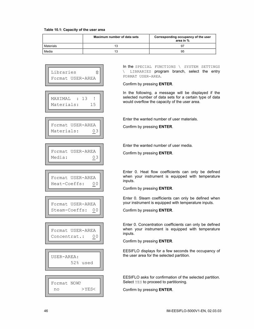
Table 10.1: Capacity of the user area
Maximum number of data sets Corresponding occupancy of the user area in %
Materials 13 97
Media 13 95
Libraries Format USER-AREA
In the SPECIAL FUNCTIONS \ SYSTEM SETTINGS \ LIBRARIES program branch, select the entry FORMAT USER-AREA.
Confirm by pressing ENTER.
MAXIMAL : 13 !Materials: 15
In the following, a message will be displayed if the selected number of data sets for a certain type of data would overflow the capacity of the user area.
Format USER-AREA Materials: 03
Enter the wanted number of user materials.
Confirm by pressing ENTER.
Format USER-AREA Media: 03
Enter the wanted number of user media.
Confirm by pressing ENTER.
Format USER-AREA Heat-Coeffs: 00
Enter 0. Heat flow coefficients can only be defined when your instrument is equipped with temperature inputs.
Confirm by pressing ENTER.
Format USER-AREA Steam-Coeffs: 00
Enter 0. Steam coefficients can only be defined when your instrument is equipped with temperature inputs.
Confirm by pressing ENTER.
Format USER-AREA Concentrat.: 00
Enter 0. Concentration coefficients can only be defined when your instrument is equipped with temperature inputs.
Confirm by pressing ENTER.
USER-AREA: 52% used
EESIFLO displays for a few seconds the occupancy of the user area for the selected partition.
Format NOW? no >YES<
EESIFLO asks for confirmation of the selected partition. Select YES to proceed to partitioning.
Confirm by pressing ENTER.

IM-EESIFLO-5000V1-EN, 02.03.03 47
FORMATTING... ...
EESIFLO formats the user area according to your inputs. This procedure takes a few seconds.
Libraries Format USER-AREA
Once the formatting is finished, EESIFLO will return to the FORMAT USER-AREA display.
Keeping Data during Formatting of the User Area When reformatting the user area, EESIFLO can keep up to 8 data sets of each type.
Example 1: You reduce the number of user materials from 5 to 3. The data sets #01 to #03 are kept. The last two data sets #04 and #05 are deleted. Example 2: You increase the number of user materials from 5 to 6. All 5 data sets are kept.
10.2.2 Extended Library Function The Extended Library function allows you to enter temperature or pressure dependent properties. The function has to be activated in the SPECIAL FUNCTIONS program branch before defining a material or medium with such properties.
Table 10.2 gives an overview of the properties that can be entered and what they are needed for.
Table 10.2: Medium and material properties that can be stored
Property Property is necessary for...
Basic data of a medium
sound velocity (MIN and MAX) start of measurement
viscosity profile correction of the flow velocity
density mass flow rate calculation
Basic data of a material
transversal sound velocity flow measurement
longitudinal sound velocity wall thickness measurement and/or flow measurement
type of sound wave to be used flow measurement
typical roughness profile correction of the flow velocity
Enter only those properties which are relevant for your measuring task.
Example: The density of a medium is unknown. If the mass flow rate is not of interest, you may set the density to any constant value. The measurement of flow velocity and volume flow is not affected by this. However, the value of the mass flow rate will be wrong.
The dependency of certain properties on process quantities (temperature, pressure) can be described by polynomials of grade 0 to 4 or by other specialized interpolation functions. In most cases although, constant values or a linear dependency are quite sufficient. For instance, if the temperature fluctuations at the measuring point are small compared with the temperature dependencies of the properties, considering a linear dependency or completely neglecting the temperature dependency will not result in a considerable additional measuring error. If the process conditions fluctuate strongly and the properties of the involved materials/media have a pronounced temperature dependency (as the viscosity of hydraulic oils for example), polynomials or other specialized functions should be used for the interpolation.
In case of doubt, consult EESIFLO to find the best solution for your specific measuring task.
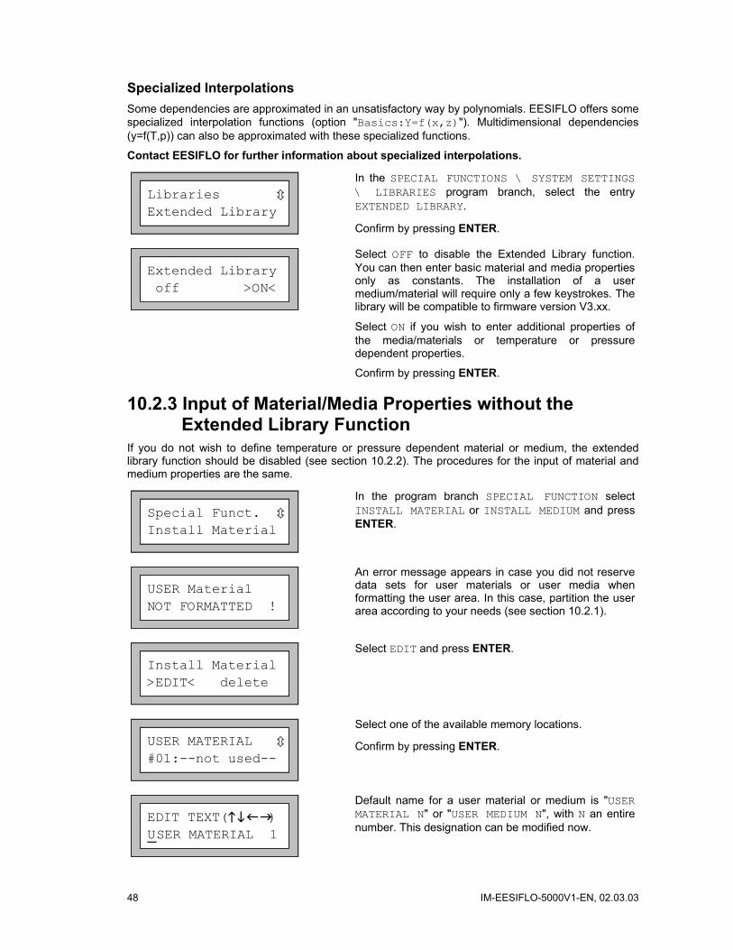
48 IM-EESIFLO-5000V1-EN, 02.03.03
Specialized Interpolations Some dependencies are approximated in an unsatisfactory way by polynomials. EESIFLO offers some specialized interpolation functions (option "Basics:Y=f(x,z)"). Multidimensional dependencies (y=f(T,p)) can also be approximated with these specialized functions.
Contact EESIFLO for further information about specialized interpolations.
Libraries Extended Library
In the SPECIAL FUNCTIONS \ SYSTEM SETTINGS \ LIBRARIES program branch, select the entry EXTENDED LIBRARY.
Confirm by pressing ENTER.
Extended Library off >ON<
Select OFF to disable the Extended Library function. You can then enter basic material and media properties only as constants. The installation of a user medium/material will require only a few keystrokes. The library will be compatible to firmware version V3.xx.
Select ON if you wish to enter additional properties of the media/materials or temperature or pressure dependent properties.
Confirm by pressing ENTER.
10.2.3 Input of Material/Media Properties without the Extended Library Function
If you do not wish to define temperature or pressure dependent material or medium, the extended library function should be disabled (see section 10.2.2). The procedures for the input of material and medium properties are the same.
Special Funct. Install Material
In the program branch SPECIAL FUNCTION select INSTALL MATERIAL or INSTALL MEDIUM and press ENTER.
USER Material NOT FORMATTED !
An error message appears in case you did not reserve data sets for user materials or user media when formatting the user area. In this case, partition the user area according to your needs (see section 10.2.1).
Install Material >EDIT< delete
Select EDIT and press ENTER.
USER MATERIAL #01:--not used--
Select one of the available memory locations.
Confirm by pressing ENTER.
EDIT TEXT( ) USER MATERIAL 1
Default name for a user material or medium is "USER MATERIAL N" or "USER MEDIUM N", with N an entire number. This designation can be modified now.
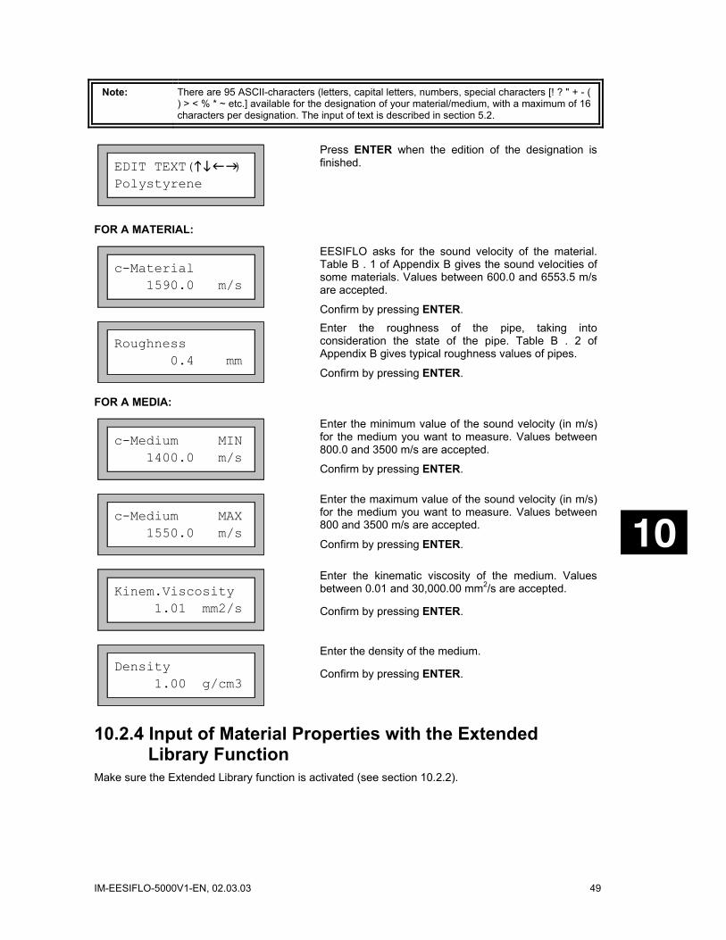
IM-EESIFLO-5000V1-EN, 02.03.03 49
Note: There are 95 ASCII-characters (letters, capital letters, numbers, special characters [! ? " + - ( ) > < % * ~ etc.] available for the designation of your material/medium, with a maximum of 16 characters per designation. The input of text is described in section 5.2.
EDIT TEXT( ) Polystyrene
Press ENTER when the edition of the designation is finished.
FOR A MATERIAL:
c-Material 1590.0 m/s
EESIFLO asks for the sound velocity of the material. Table B . 1 of Appendix B gives the sound velocities of some materials. Values between 600.0 and 6553.5 m/s are accepted.
Confirm by pressing ENTER.
Roughness 0.4 mm
Enter the roughness of the pipe, taking into consideration the state of the pipe. Table B . 2 of Appendix B gives typical roughness values of pipes.
Confirm by pressing ENTER.
FOR A MEDIA:
c-Medium MIN 1400.0 m/s
Enter the minimum value of the sound velocity (in m/s) for the medium you want to measure. Values between 800.0 and 3500 m/s are accepted.
Confirm by pressing ENTER.
c-Medium MAX 1550.0 m/s
Enter the maximum value of the sound velocity (in m/s) for the medium you want to measure. Values between 800 and 3500 m/s are accepted.
Confirm by pressing ENTER.
Kinem.Viscosity 1.01 mm2/s
Enter the kinematic viscosity of the medium. Values between 0.01 and 30,000.00 mm2/s are accepted.
Confirm by pressing ENTER.
Density 1.00 g/cm3
Enter the density of the medium.
Confirm by pressing ENTER.
10.2.4 Input of Material Properties with the Extended Library Function
Make sure the Extended Library function is activated (see section 10.2.2).
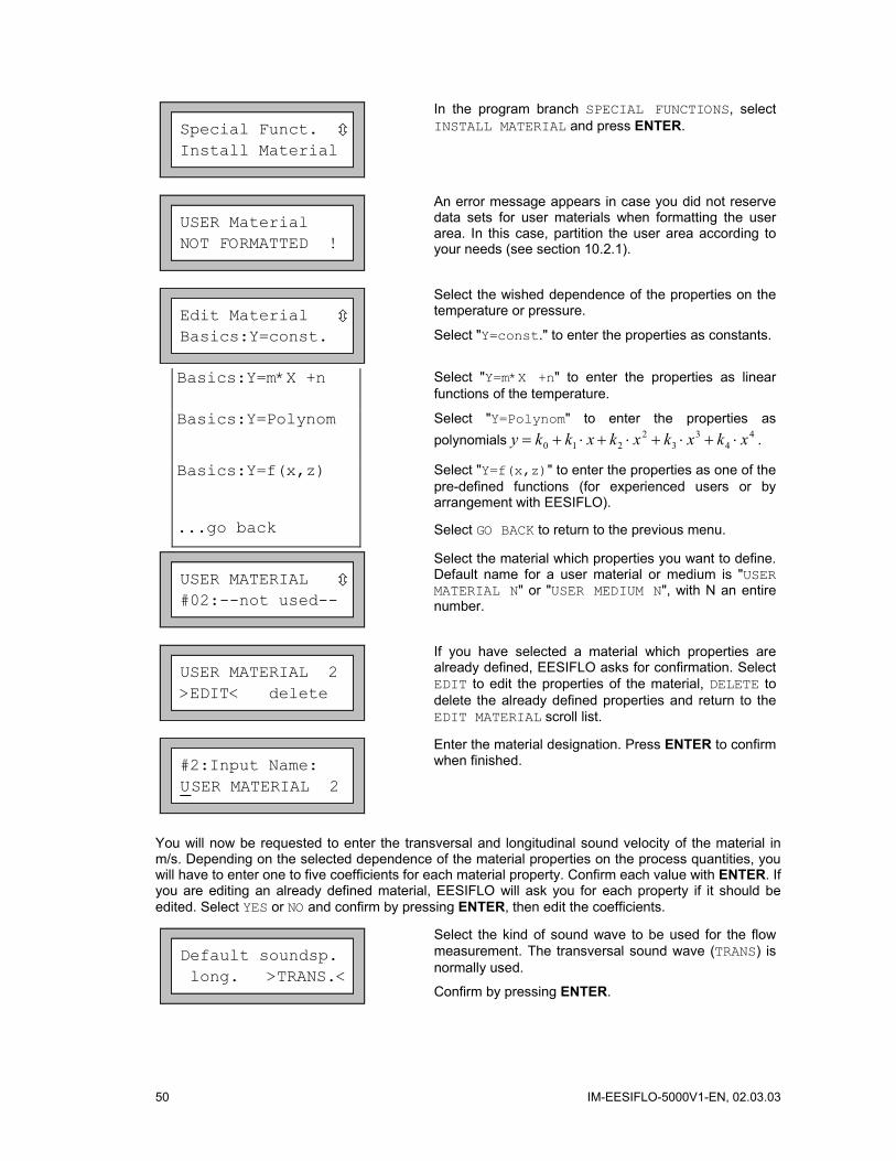
50 IM-EESIFLO-5000V1-EN, 02.03.03
Special Funct. Install Material
In the program branch SPECIAL FUNCTIONS, select INSTALL MATERIAL and press ENTER.
USER Material NOT FORMATTED !
An error message appears in case you did not reserve data sets for user materials when formatting the user area. In this case, partition the user area according to your needs (see section 10.2.1).
Edit Material Basics:Y=const.
Select the wished dependence of the properties on the temperature or pressure.
Select "Y=const." to enter the properties as constants.
Basics:Y=m*X +n Select "Y=m*X +n" to enter the properties as linear functions of the temperature.
Basics:Y=Polynom Select "Y=Polynom" to enter the properties as polynomials 4
43
32
210 xkxkxkxkky ⋅+⋅+⋅+⋅+= .
Basics:Y=f(x,z) Select "Y=f(x,z)" to enter the properties as one of the pre-defined functions (for experienced users or by arrangement with EESIFLO).
...go back Select GO BACK to return to the previous menu.
USER MATERIAL #02:--not used--
Select the material which properties you want to define. Default name for a user material or medium is "USER MATERIAL N" or "USER MEDIUM N", with N an entire number.
USER MATERIAL 2 >EDIT< delete
If you have selected a material which properties are already defined, EESIFLO asks for confirmation. Select EDIT to edit the properties of the material, DELETE to delete the already defined properties and return to the EDIT MATERIAL scroll list.
#2:Input Name: USER MATERIAL 2
Enter the material designation. Press ENTER to confirm when finished.
You will now be requested to enter the transversal and longitudinal sound velocity of the material in m/s. Depending on the selected dependence of the material properties on the process quantities, you will have to enter one to five coefficients for each material property. Confirm each value with ENTER. If you are editing an already defined material, EESIFLO will ask you for each property if it should be edited. Select YES or NO and confirm by pressing ENTER, then edit the coefficients.
Default soundsp. long. >TRANS.<
Select the kind of sound wave to be used for the flow measurement. The transversal sound wave (TRANS) is normally used.
Confirm by pressing ENTER.
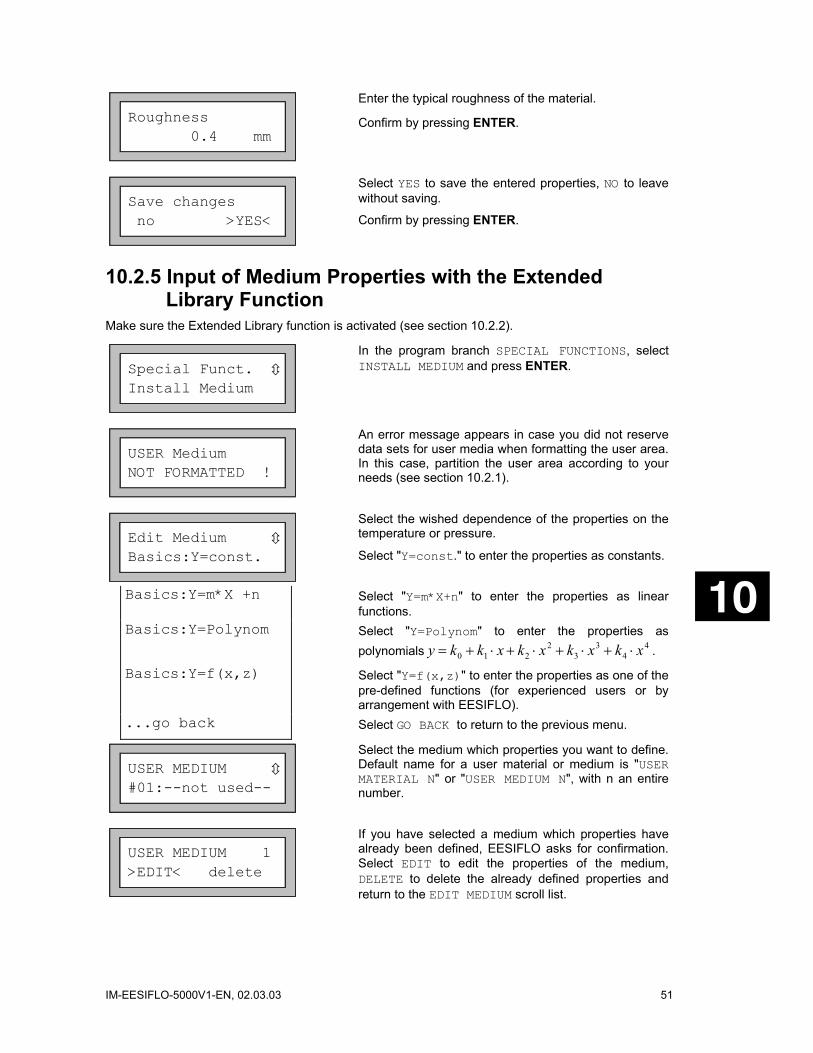
IM-EESIFLO-5000V1-EN, 02.03.03 51
Roughness 0.4 mm
Enter the typical roughness of the material.
Confirm by pressing ENTER.
Save changes no >YES<
Select YES to save the entered properties, NO to leave without saving.
Confirm by pressing ENTER.
10.2.5 Input of Medium Properties with the Extended Library Function
Make sure the Extended Library function is activated (see section 10.2.2).
Special Funct. Install Medium
In the program branch SPECIAL FUNCTIONS, select INSTALL MEDIUM and press ENTER.
USER Medium NOT FORMATTED !
An error message appears in case you did not reserve data sets for user media when formatting the user area. In this case, partition the user area according to your needs (see section 10.2.1).
Edit Medium Basics:Y=const.
Select the wished dependence of the properties on the temperature or pressure.
Select "Y=const." to enter the properties as constants.
Basics:Y=m*X +n Select "Y=m*X+n" to enter the properties as linear functions.
Basics:Y=Polynom Select "Y=Polynom" to enter the properties as polynomials 4
43
32
210 xkxkxkxkky ⋅+⋅+⋅+⋅+= .
Basics:Y=f(x,z) Select "Y=f(x,z)" to enter the properties as one of the pre-defined functions (for experienced users or by arrangement with EESIFLO).
...go back Select GO BACK to return to the previous menu.
USER MEDIUM #01:--not used--
Select the medium which properties you want to define. Default name for a user material or medium is "USER MATERIAL N" or "USER MEDIUM N", with n an entire number.
USER MEDIUM 1 >EDIT< delete
If you have selected a medium which properties have already been defined, EESIFLO asks for confirmation. Select EDIT to edit the properties of the medium, DELETE to delete the already defined properties and return to the EDIT MEDIUM scroll list.

52 IM-EESIFLO-5000V1-EN, 02.03.03
#1:Input Name: USER MEDIUM 1
Enter the medium designation. Press ENTER to confirm when finished.
You will now be requested to enter the longitudinal sound velocity (in m/s), the kinematic viscosity (in mm2/s) and the density (in g/mm3) of the medium. Depending on the selected dependence of the medium properties on the process quantities, you will have to enter one to five coefficients for each medium property. Confirm each value by pressing ENTER. If you are editing an already defined medium, EESIFLO will ask you for each property if it should be edited. Select YES or NO and confirm by pressing ENTER, then edit the coefficients.
Save changes no >YES<
Select YES to save the entered properties, NO to leave without saving.
Confirm by pressing ENTER.
10.2.6 Deleting a User Material or User Medium To delete a user material or medium, proceed as follows:
Install Material edit >DELETE<
In the program branch SPECIAL FUNCTION, select INSTALL MATERIAL or INSTALL MEDIUM and press ENTER.
Select DELETE and confirm by pressing ENTER.
USER MATERIAL #01:Polystyrene
Select the user material or medium to be deleted.
Confirm by pressing ENTER.
Really Delete? no >YES<
EESIFLO asks for confirmation. Select YES or NO.
Confirm your selection by pressing ENTER.

IM-EESIFLO-5000V1-EN, 02.03.03 53
11 Settings
11.1 Setting the Internal Clock EESIFLO features a battery buffered clock. During measurement, the data are automatically stamped with date and time.
11.1.1 Setting the Time
SYSTEM settings Set Clock
In the program branch SPECIAL FUNCTION, select the SYSTEM SETTINGS option.
Confirm by pressing ENTER.
TIME 11:00 ok >NEW<
The actual time is displayed. Select OK to confirm or NEW to set the time.
Confirm by pressing ENTER.
TIME 11:0 0 Set Time !
Use key to select the digit to be edited. See section 5.2 for more information on the numeric input mode.
Use keys and to edit the selected digit.
Confirm your setting by pressing ENTER.
TIME 11:11 >OK< new
The next display shows the newly set time. Select OK to confirm or NEW to set the time again.
Confirm by pressing ENTER.
11.1.2 Setting the Date
DATE 25.01.2002 ok >NEW<
After the time has been set, the DATE display will appear. Select OK to confirm or NEW to set the date.
Confirm by pressing ENTER.
DATE 25.01.2002 Set Date !
Use key to select the digit to be edited. See section 5.2 for more information on the numeric input mode.
Use keys and to edit the selected digit.
Confirm your setting by pressing ENTER.
DATE 26.01.2002 >OK< new
The next display shows the newly set date and asks for confirmation. Select OK to confirm or NEW to set the date again.
Confirm by pressing ENTER.
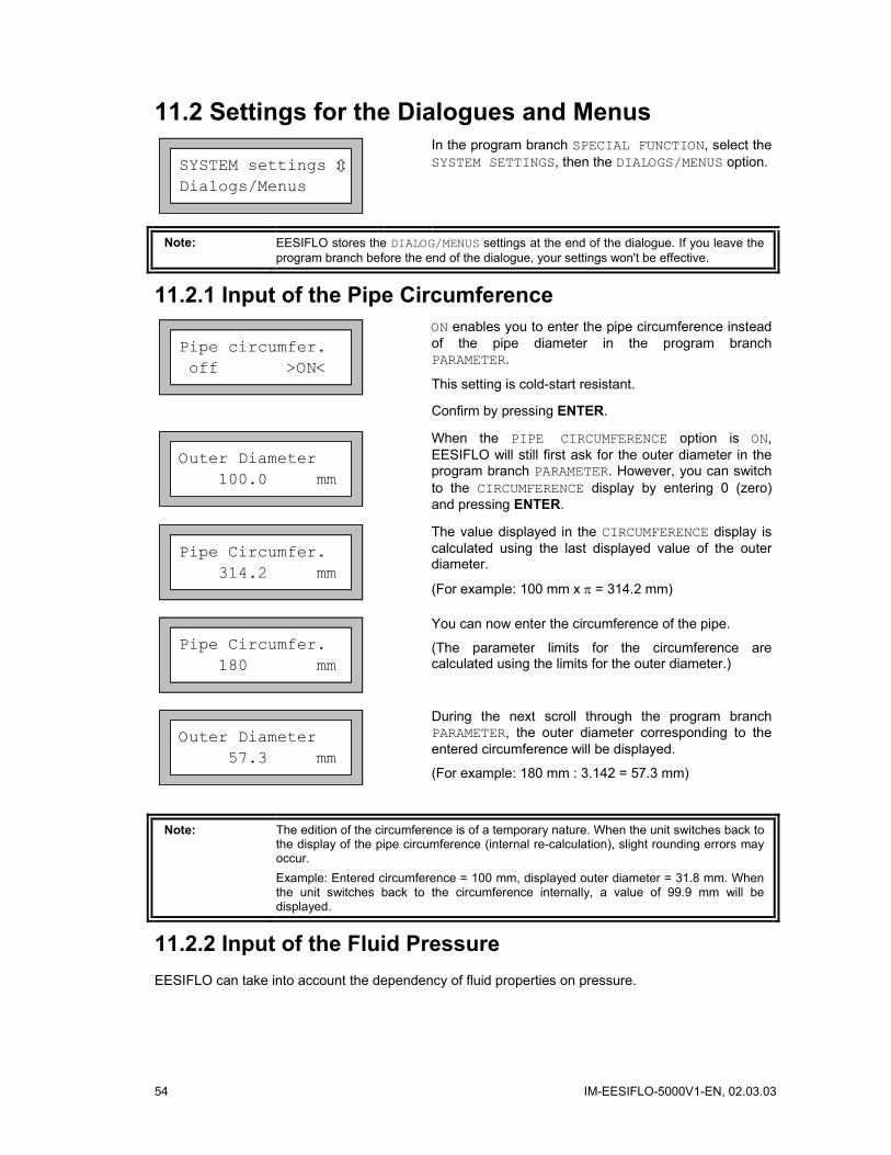
54 IM-EESIFLO-5000V1-EN, 02.03.03
11.2 Settings for the Dialogues and Menus
SYSTEM settings Dialogs/Menus
In the program branch SPECIAL FUNCTION, select the SYSTEM SETTINGS, then the DIALOGS/MENUS option.
Note: EESIFLO stores the DIALOG/MENUS settings at the end of the dialogue. If you leave the program branch before the end of the dialogue, your settings won't be effective.
11.2.1 Input of the Pipe Circumference
Pipe circumfer. off >ON<
ON enables you to enter the pipe circumference instead of the pipe diameter in the program branch PARAMETER.
This setting is cold-start resistant.
Confirm by pressing ENTER.
Outer Diameter 100.0 mm
When the PIPE CIRCUMFERENCE option is ON, EESIFLO will still first ask for the outer diameter in the program branch PARAMETER. However, you can switch to the CIRCUMFERENCE display by entering 0 (zero) and pressing ENTER.
Pipe Circumfer. 314.2 mm
The value displayed in the CIRCUMFERENCE display is calculated using the last displayed value of the outer diameter.
(For example: 100 mm x π = 314.2 mm)
Pipe Circumfer. 180 mm
You can now enter the circumference of the pipe.
(The parameter limits for the circumference are calculated using the limits for the outer diameter.)
Outer Diameter 57.3 mm
During the next scroll through the program branch PARAMETER, the outer diameter corresponding to the entered circumference will be displayed.
(For example: 180 mm : 3.142 = 57.3 mm)
Note: The edition of the circumference is of a temporary nature. When the unit switches back to the display of the pipe circumference (internal re-calculation), slight rounding errors may occur. Example: Entered circumference = 100 mm, displayed outer diameter = 31.8 mm. When the unit switches back to the circumference internally, a value of 99.9 mm will be displayed.
11.2.2 Input of the Fluid Pressure EESIFLO can take into account the dependency of fluid properties on pressure.

IM-EESIFLO-5000V1-EN, 02.03.03 55
Fluid pressure off >ON<
In the FLUID PRESSURE display, select ON if you wish to activate the fluid pressure query in the program branch PARAMETER. The fluid pressure must lie between 1 and 600 bar.
If you select OFF, EESIFLO uses a fluid pressure of 1.0 bar in all calculations.
11.2.3 Input mode for the Measuring Point Designation
Meas.Point No.: - ( )
Select "1234" if you wish to identify the measuring points using only numbers, point and dash.
Select " " if you wish to enter the measuring point designations using the ASCII-editor (see section 5.2).
11.2.4 Display of the Last Entered Transducer Distance
Transd. Distance auto >USER<
If you select TRANSDUCER DISTANCE \ USER, EESIFLO will display the last precise transducer distance you have entered after positioning of the transducers.
Transd.Distance? (50.8) 50.0 mm
If the suggested transducer distance and the entered distance are not identical, the suggested value is then displayed in parenthesis on the left, followed by the last precise transducer distance entered. This setting is recommended if you always measure at the same measuring point.
Transd.Distance? 50.8 mm
If you select TRANDUCER DISTANCE \ AUTO, EESIFLO will only display the suggested transducer distance after the positioning of the transducers. This setting is recommended if the measuring point changes often.
11.2.5 Error-Value Delay
Error-val. delay damping >EDIT<
EDIT enables you to enter an error-value delay. The error-value delay is the time after which a special error value will be sent to an output when no valid measured values are available. If you select DAMPING, EESIFLO uses the value of the damping as error-value delay.
See section 14.1.2 and 14.2 for more information on the behavior of EESIFLO in case no measured values can be obtained.
11.2.6 Display of the Alarms' State
SHOW RELAIS STAT off >ON<
ON activates the display of the alarms' state during measurement.
See section 14.5 for more information on the alarm outputs.

56 IM-EESIFLO-5000V1-EN, 02.03.03
Note: EESIFLO stores all changes now at the end of the configuration dialogue.
11.3 Measurement Settings
SYSTEM settings Measuring
In the program branch SPECIAL FUNCTION, select the SYSTEM SETTINGS, then the MEASURING option.
Note: EESIFLO stores the MEASURING settings at the end of the dialogue. If you leave the program branch before the end of the dialogue, your settings won't be effective.
SKYDROL Korrect >OFF< on
Select OFF and confirm by pressing ENTER.
Flow Velocity >NORMAL< uncorr.
Select NORMAL to always have the profile corrected flow values displayed and output, UNCORR. to obtain flow values without flow profile correction for output and data storage. This setting is cold-start resistant. See section 9.6 for more information about this option.
Confirm by pressing ENTER.
Cut-off Flow >ABSOLUTE< sign
Cut-off Flow factory >USER<
You can define here a lower limit for the flow velocity. See section 9.5.
Velocity limit 24.0 m/s
You can enter here an upper limit for the flow velocity (see section 9.4). Values between 0.1 and 25.5 m/s are accepted. Entering "0" switches off the flow velocity control.
Quant. wrapping off >ON<
Select here the overflow option of the totalizers. See section 9.3.2.
Quantity recall off >ON<
In the QUANTITY RECALL display, select ON if you wish that the previous numerical values of the total-izers are kept after restart of the measurement. Select OFF if you wish the totalizers to be reset to zero after restart of the measurement.
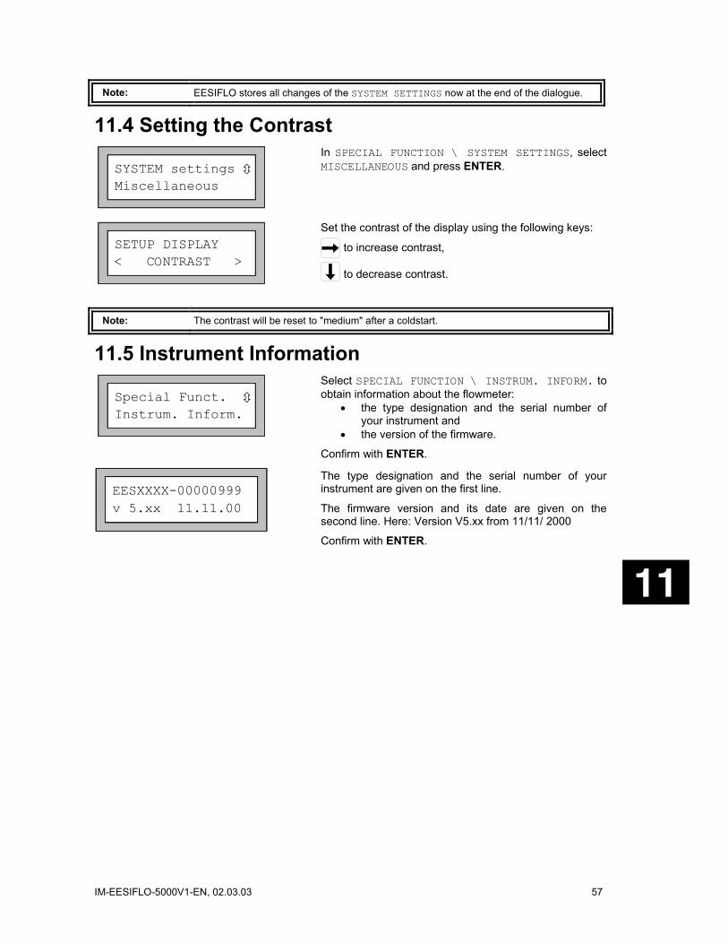
IM-EESIFLO-5000V1-EN, 02.03.03 57
Note: EESIFLO stores all changes of the SYSTEM SETTINGS now at the end of the dialogue.
11.4 Setting the Contrast
SYSTEM settings Miscellaneous
In SPECIAL FUNCTION \ SYSTEM SETTINGS, select MISCELLANEOUS and press ENTER.
SETUP DISPLAY < CONTRAST >
Set the contrast of the display using the following keys:
to increase contrast,
to decrease contrast.
Note: The contrast will be reset to "medium" after a coldstart.
11.5 Instrument Information
Special Funct. Instrum. Inform.
Select SPECIAL FUNCTION \ INSTRUM. INFORM. to obtain information about the flowmeter:
• the type designation and the serial number of your instrument and
• the version of the firmware.
Confirm with ENTER.
The type designation and the serial number of your instrument are given on the first line.
The firmware version and its date are given on the second line. Here: Version V5.xx from 11/11/ 2000
Confirm with ENTER.
EESXXXX-00000999 v 5.xx 11.11.00

58 IM-EESIFLO-5000V1-EN, 02.03.03

IM-EESIFLO-5000V1-EN, 02.03.03 59
12 SuperUser Mode The SuperUser mode gives you the opportunity for experimental work.
Features of the SuperUser mode:
• The flowmeter operates without observing pre-set standard parameters
• There are no plausibility checks when parameters are being entered.
• EESIFLO does not control if the entered values respect the limits given by physical laws and specifications.
• The cut-off flow velocity is not active.
• The sound path factor must always be entered numerically.
It is possible to modify the value of the minimal pipe inner diameter accepted by EESIFLO for a certain type of transducer without entering the SuperUser mode. Refer to section 9.7.
12.1 Activating/Deactivating Enter the HotCode 071049 to activate the SuperUser mode.
SUPERUSER MODE *IS ACTIVE NOW *
EESIFLO indicates that the SuperUser mode is activated.
Confirm by pressing ENTER. The main menu will appear again.
Enter the HotCode 071049 again to deactivate the SuperUser mode.
SUPERUSER MODE IS PASSIVE NOW
EESIFLO then indicates that the SuperUser mode is deactivated.
Confirm by pressing ENTER. The main menu will appear again.
You can also deactivate the SuperUser mode by switching EESIFLO off.
12.2 Transducer Parameters In SuperUser mode, the TRANSDUCER TYPE display will appear at the end of parameter input even though the transducers were detected and recognized by the instrument.
Transducer Type Q2E-314
Confirm the displayed transducer type (here: Q2E-314) or select a transducer type in the scroll list. If you wish to edit the transducer parameters, select the option SPECIAL VERSION. Confirm by pressing ENTER.
Transd. Data 1 35.99
If you have selected SPECIAL VERSION, EESIFLO will ask for the transducer data. Enter the value of the 6 transducer parameters as given on the transducer data card, confirming each entry with ENTER.
60 IM-EESIFLO-5000V1-EN, 02.03.03
12.3 Malfunctions in SuperUser Mode Since the SuperUser mode operates without any plausibility checks, nonsensical entries may result in an automatic switching-off of the instrument or in a crash of the internal software. This would occur, for example, if you enter 0 (zero) as the number of sound paths or if you specify an outer diameter of 0.1 mm.
In such a case, switch the flowmeter ON again and reactivate the SuperUser mode.
If necessary, RESET the instrument by pressing keys BRK, C and ENTER simultaneously.
Note: Switching OFF and resetting both deactivate the SuperUser mode.
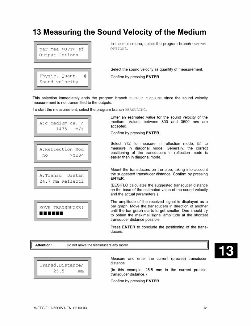
IM-EESIFLO-5000V1-EN, 02.03.03 61
13 Measuring the Sound Velocity of the Medium
par mea >OPT< sf Output Options
In the main menu, select the program branch OUTPUT OPTIONS.
Physic. Quant. Sound velocity
Select the sound velocity as quantity of measurement.
Confirm by pressing ENTER.
This selection immediately ends the program branch OUTPUT OPTIONS since the sound velocity measurement is not transmitted to the outputs.
To start the measurement, select the program branch MEASURING.
A:c-Medium ca. ? 1475 m/s
Enter an estimated value for the sound velocity of the medium. Values between 800 and 3500 m/s are accepted.
Confirm by pressing ENTER.
A:Reflection Mod no >YES<
Select YES to measure in reflection mode, NO to measure in diagonal mode. Generally, the correct positioning of the transducers in reflection mode is easier than in diagonal mode.
A:Transd. Distan 24.7 mm Reflecti
Mount the transducers on the pipe, taking into account the suggested transducer distance. Confirm by pressing ENTER.
(EESIFLO calculates the suggested transducer distance on the base of the estimated value of the sound velocity and the actual parameters.)
MOVE TRANSDUCER!
The amplitude of the received signal is displayed as a bar graph. Move the transducers in direction of another until the bar graph starts to get smaller. One should try to obtain the maximal signal amplitude at the shortest transducer distance possible.
Press ENTER to conclude the positioning of the trans-ducers.
Attention! Do not move the transducers any more!
Transd.Distance? 25.5 mm
Measure and enter the current (precise) transducer distance.
(In this example, 25.5 mm is the current precise transducer distance.)
Confirm by pressing ENTER.
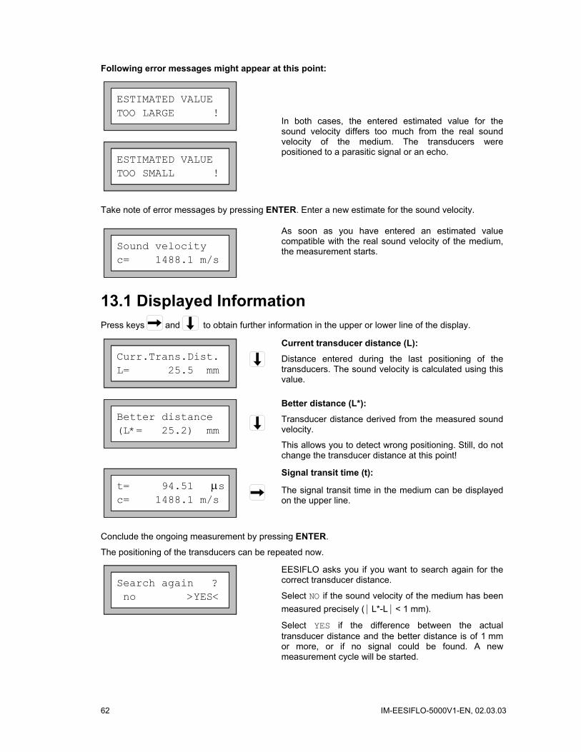
62 IM-EESIFLO-5000V1-EN, 02.03.03
Following error messages might appear at this point:
ESTIMATED VALUE TOO LARGE !
ESTIMATED VALUE TOO SMALL !
In both cases, the entered estimated value for the sound velocity differs too much from the real sound velocity of the medium. The transducers were positioned to a parasitic signal or an echo.
Take note of error messages by pressing ENTER. Enter a new estimate for the sound velocity.
Sound velocity c= 1488.1 m/s
As soon as you have entered an estimated value compatible with the real sound velocity of the medium, the measurement starts.
13.1 Displayed Information Press keys and to obtain further information in the upper or lower line of the display.
Curr.Trans.Dist. L= 25.5 mm
Current transducer distance (L):
Distance entered during the last positioning of the transducers. The sound velocity is calculated using this value.
Better distance (L*= 25.2) mm
Better distance (L*):
Transducer distance derived from the measured sound velocity.
This allows you to detect wrong positioning. Still, do not change the transducer distance at this point!
t= 94.51 µs c= 1488.1 m/s
Signal transit time (t):
The signal transit time in the medium can be displayed on the upper line.
Conclude the ongoing measurement by pressing ENTER.
The positioning of the transducers can be repeated now.
Search again ? no >YES<
EESIFLO asks you if you want to search again for the correct transducer distance.
Select NO if the sound velocity of the medium has been measured precisely ( | L*-L | < 1 mm).
Select YES if the difference between the actual transducer distance and the better distance is of 1 mm or more, or if no signal could be found. A new measurement cycle will be started.
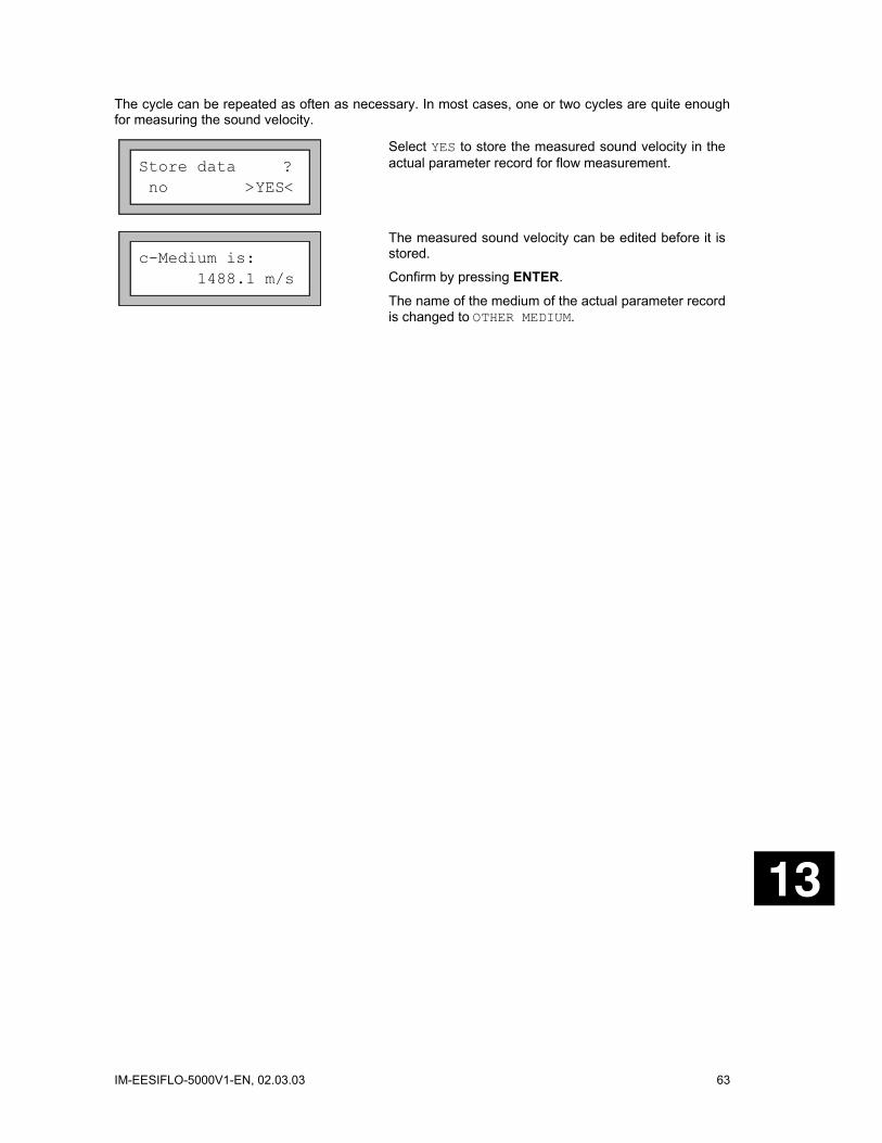
IM-EESIFLO-5000V1-EN, 02.03.03 63
The cycle can be repeated as often as necessary. In most cases, one or two cycles are quite enough for measuring the sound velocity.
Store data ? no >YES<
Select YES to store the measured sound velocity in the actual parameter record for flow measurement.
c-Medium is: 1488.1 m/s
The measured sound velocity can be edited before it is stored.
Confirm by pressing ENTER.
The name of the medium of the actual parameter record is changed to OTHER MEDIUM.

64 IM-EESIFLO-5000V1-EN, 02.03.03

IM-EESIFLO-5000V1-EN, 02.03.03 65
14 Process Outputs If your instrument is equipped with process outputs, these outputs must be installed and activated before they can be used.
To install an output, you must:
• Define the measured value that should transmitted to the output (source item) and the properties of the signal.
• Define the behavior of the output in case no valid measured values are available.
Afterward, the installed output must be activated (program branch OUTPUT OPTIONS). Only after this procedure has been gone through will measured values be available at the outputs.
14.1 Installation of a Process Output The installation of the process outputs takes place in the SPECIAL FUNCTION \ SYSTEM SETTINGS \ PROCESS OUTPUTS program branch.
Note: EESIFLO stores the configuration of an output at the end of the installation dialogue. If you leave the installation dialogue by pressing BRK, changes won't be saved.
SYSTEM settings Proc. outputs
In the SPECIAL FUNCTION \ SYSTEM SETTINGS program branch, select the PROCESS OUTPUTS option. Confirm by pressing ENTER.
Install Output Current I1
Select the output you want to install. The scroll list contains all the actually available process outputs. A tick ( ) after an item of the list means that this output has already been installed. Confirm by pressing ENTER.
I1 enable no >YES<
This display will appear if the selected output was not already enabled.
Select YES and confirm by pressing ENTER.
I1 disable >NO< yes
If the selected output was already enabled, select NO to reconfigurate it, or YES to go back to the previous menu and select another output.
Confirm by pressing ENTER.
I1 Source item Flow
Select the measuring quantity that should be transmitted to the output (source item). The available source items and their configuration option are described in the table below. If you are configurating a binary output, only the options LIMIT and IMPULSE are offered.
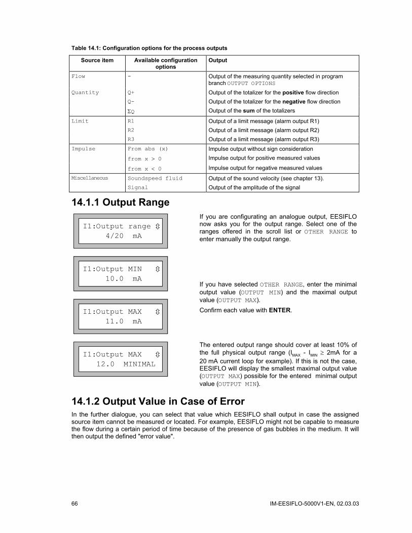
66 IM-EESIFLO-5000V1-EN, 02.03.03
Table 14.1: Configuration options for the process outputs
Source item Available configuration options
Output
Flow - Output of the measuring quantity selected in program branch OUTPUT OPTIONS
Quantity Q+ Output of the totalizer for the positive flow direction Q- Output of the totalizer for the negative flow direction ΣQ Output of the sum of the totalizers
Limit R1 Output of a limit message (alarm output R1) R2 Output of a limit message (alarm output R2) R3 Output of a limit message (alarm output R3) Impulse From abs (x) Impulse output without sign consideration from x > 0 Impulse output for positive measured values
from x < 0 Impulse output for negative measured values
Miscellaneous Soundspeed fluid Output of the sound velocity (see chapter 13). Signal Output of the amplitude of the signal
14.1.1 Output Range
I1:Output range 4/20 mA
If you are configurating an analogue output, EESIFLO now asks you for the output range. Select one of the ranges offered in the scroll list or OTHER RANGE to enter manually the output range.
I1:Output MIN 10.0 mA
I1:Output MAX 11.0 mA
If you have selected OTHER RANGE, enter the minimal output value (OUTPUT MIN) and the maximal output value (OUTPUT MAX). Confirm each value with ENTER.
I1:Output MAX 12.0 MINIMAL
The entered output range should cover at least 10% of the full physical output range (IMAX - IMIN ≥ 2mA for a 20 mA current loop for example). If this is not the case, EESIFLO will display the smallest maximal output value (OUTPUT MAX) possible for the entered minimal output value (OUTPUT MIN).
14.1.2 Output Value in Case of Error In the further dialogue, you can select that value which EESIFLO shall output in case the assigned source item cannot be measured or located. For example, EESIFLO might not be capable to measure the flow during a certain period of time because of the presence of gas bubbles in the medium. It will then output the defined "error value".

IM-EESIFLO-5000V1-EN, 02.03.03 67
Table 14.2: Error value options
Error value option Result Minimum Output of the lowest possible value (lower limit of the output range) Hold last value Output of the last measured value Maximum Output of the highest possible value (upper limit of the output range) Other value Output of a value to be defined within the physical limits of the output.
Example:
The flow volume was selected as source item for the current loop, the current loop range was set to 4/20 mA, the error value delay td to a value greater as zero.
The measurement of the volume flow rate is impossible during the time interval t0...t1.
What signal should be output during this time interval?
???v [m3/h]
tt0 t1
Fig. 14.1: Error value delay
Table 14.3: Error value options
Selected error value option Output signal
Error-value Minimum (4.0mA)
I [mA]
20
4t
td
Error-value Hold last value
I [mA]
20
4t
Error-value Maximum (20.0mA)
I [mA]
20
4
t
td
Error-value Other value ...
Error-Value = 2.00 mA
I [mA]
20
4
t
td

68 IM-EESIFLO-5000V1-EN, 02.03.03
Error-value Minimum (4.0mA)
Select an error value in the scroll list.
Confirm by pressing ENTER.
Error-value: ...
If you have selected OTHER VALUE, enter an error value now. The value must be within the physical limits of the process output.
Confirm by pressing ENTER.
Note: EESIFLO stores your settings now at the end of the dialogue.
I1 active loop Terminal:P1+,P1-
The terminals to be used for the connection of the output are now displayed (here: P1+ and P1- for the active current loop).
Confirm by pressing ENTER.
14.1.3 Function Check Finally, you can test the function of the installed output. Connect the terminals assigned to the output you have installed to a multimeter.
Test of analogue outputs
I1:Output Test 4 mA
Enter a test value (in our example, the current output is tested). The test value should be in the selected output range. Confirm by pressing ENTER.
I1= 4.0 mA Again? no >YES<
The input functions correctly if the measuring instrument displays the entered value. Select YES to repeat the test, NO to return to the SYSTEM SETTINGS. Confirm by pressing ENTER.
Test of binary outputs
B1:Output Test Reed-Relais OFF
In the OUTPUT TEST scroll list, select OFF to test the de-energized state of the output. Confirm by pressing ENTER. No current should be flowing at the output now.
B1= OFF Again? no >YES<
Select YES. Confirm by pressing ENTER.

IM-EESIFLO-5000V1-EN, 02.03.03 69
B1:Output Test Reed-Relais ON
In the OUTPUT TEST scroll list, select ON to test the energized state of the output. Confirm by pressing ENTER. A current should be flowing now.
B1= ON Again? no >YES<
Select YES to repeat the test, NO to return to the SYSTEM SETTINGS. Confirm by pressing ENTER.
14.2 Defining the Error Value Delay The error value delay is the time interval after which EESIFLO will transmit the error value to the output in case no valid measured values are available.
The error value delay can be entered in the OUTPUT OPTIONS program branch if this inquiry has been previously activated in the program branch SPECIAL FUNCTION. If you don't enter a specific value for the delay, EESIFLO will use the damping value.
Error-val.delay >DAMPING< edit
In the SPECIAL FUNCTION \ SYSTEM SETTINGS \DIALOGS/MENUS program branch, select the ERROR-VAL. DELAY option.
Error-val.delay 10 s
Select DAMPING if you wish the damping factor to be used as error-value delay (default setting). Select EDIT to activate the error value delay inquiry. From now on, EESIFLO will ask for the error value delay in the program branch OUTPUT OPTIONS.
This setting is coldstart resistant.
14.3 Activation of an Analogue Output Note: An output can only be activated in the program branch OUTPUT OPTIONS if it has been
previously installed.
par mea >OPT< sf Output Options
In the main menu, select the program branch OUTPUT OPTIONS.
Current Loop I1: no >YES<
Select YES in the display of the output to be activated.
Confirm by pressing ENTER.
14.3.1 Scale Values for the Analogue Outputs After you have activated an analogue output in the program branch OUTPUT OPTIONS, EESIFLO will ask for the scale values for the source item.
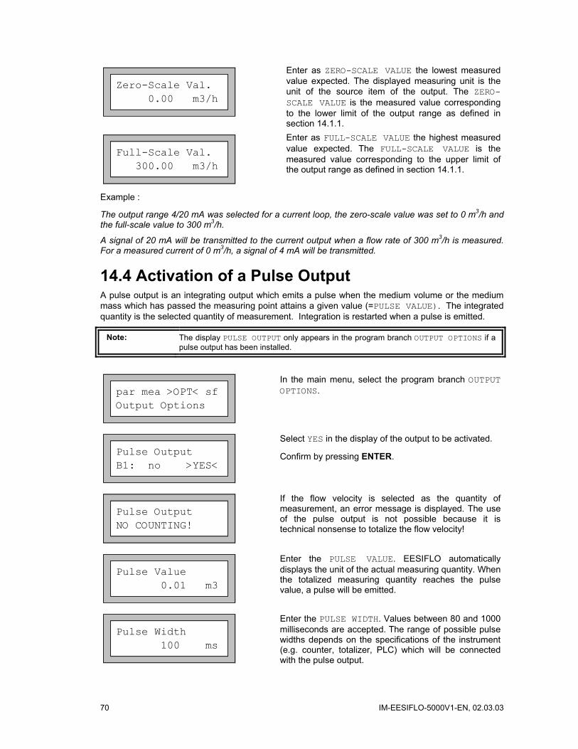
70 IM-EESIFLO-5000V1-EN, 02.03.03
Zero-Scale Val. 0.00 m3/h
Enter as ZERO-SCALE VALUE the lowest measured value expected. The displayed measuring unit is the unit of the source item of the output. The ZERO-SCALE VALUE is the measured value corresponding to the lower limit of the output range as defined in section 14.1.1.
Full-Scale Val. 300.00 m3/h
Enter as FULL-SCALE VALUE the highest measured value expected. The FULL-SCALE VALUE is the measured value corresponding to the upper limit of the output range as defined in section 14.1.1.
Example :
The output range 4/20 mA was selected for a current loop, the zero-scale value was set to 0 m3/h and the full-scale value to 300 m3/h.
A signal of 20 mA will be transmitted to the current output when a flow rate of 300 m3/h is measured. For a measured current of 0 m3/h, a signal of 4 mA will be transmitted.
14.4 Activation of a Pulse Output A pulse output is an integrating output which emits a pulse when the medium volume or the medium mass which has passed the measuring point attains a given value (=PULSE VALUE). The integrated quantity is the selected quantity of measurement. Integration is restarted when a pulse is emitted.
Note: The display PULSE OUTPUT only appears in the program branch OUTPUT OPTIONS if a pulse output has been installed.
par mea >OPT< sf Output Options
In the main menu, select the program branch OUTPUT OPTIONS.
Pulse Output B1: no >YES<
Select YES in the display of the output to be activated.
Confirm by pressing ENTER.
Pulse Output NO COUNTING!
If the flow velocity is selected as the quantity of measurement, an error message is displayed. The use of the pulse output is not possible because it is technical nonsense to totalize the flow velocity!
Pulse Value 0.01 m3
Enter the PULSE VALUE. EESIFLO automatically displays the unit of the actual measuring quantity. When the totalized measuring quantity reaches the pulse value, a pulse will be emitted.
Pulse Width 100 ms
Enter the PULSE WIDTH. Values between 80 and 1000 milliseconds are accepted. The range of possible pulse widths depends on the specifications of the instrument (e.g. counter, totalizer, PLC) which will be connected with the pulse output.
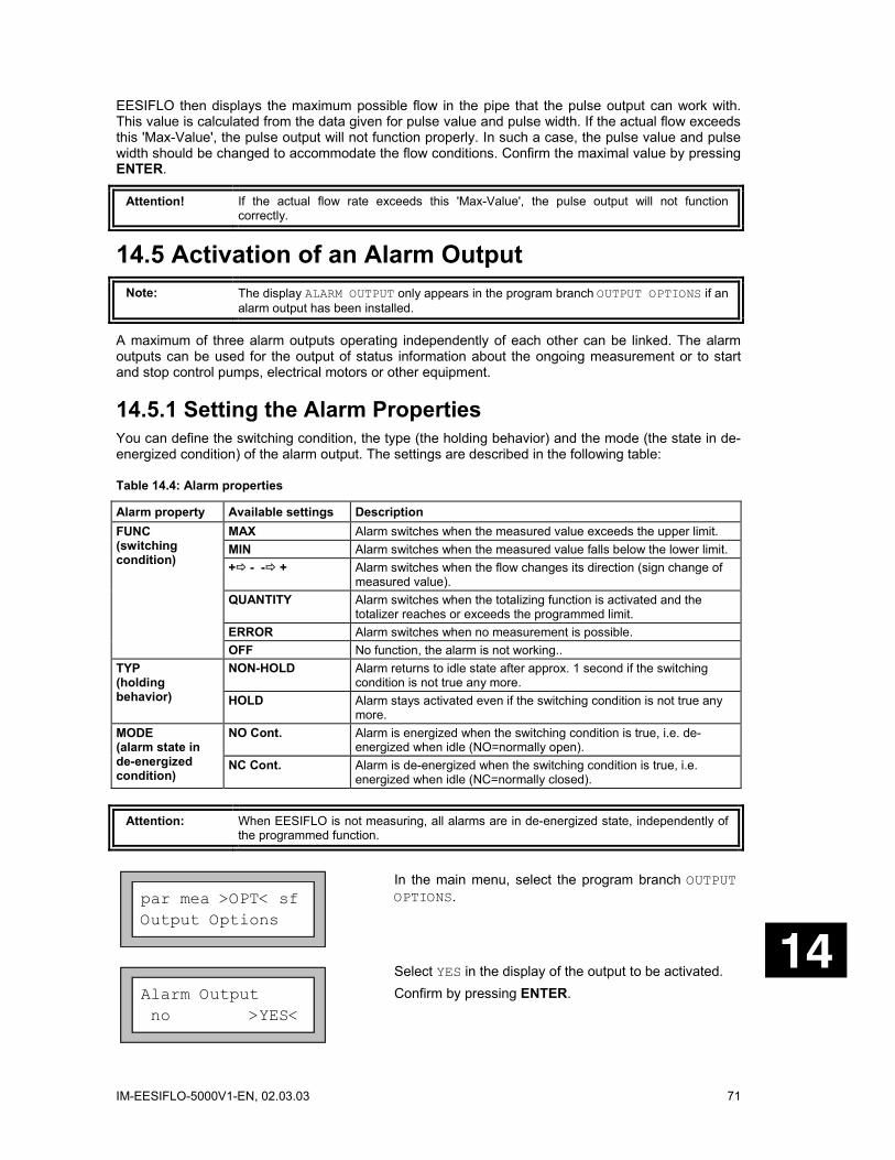
IM-EESIFLO-5000V1-EN, 02.03.03 71
EESIFLO then displays the maximum possible flow in the pipe that the pulse output can work with. This value is calculated from the data given for pulse value and pulse width. If the actual flow exceeds this 'Max-Value', the pulse output will not function properly. In such a case, the pulse value and pulse width should be changed to accommodate the flow conditions. Confirm the maximal value by pressing ENTER.
Attention! If the actual flow rate exceeds this 'Max-Value', the pulse output will not function correctly.
14.5 Activation of an Alarm Output Note: The display ALARM OUTPUT only appears in the program branch OUTPUT OPTIONS if an
alarm output has been installed.
A maximum of three alarm outputs operating independently of each other can be linked. The alarm outputs can be used for the output of status information about the ongoing measurement or to start and stop control pumps, electrical motors or other equipment.
14.5.1 Setting the Alarm Properties You can define the switching condition, the type (the holding behavior) and the mode (the state in de-energized condition) of the alarm output. The settings are described in the following table:
Table 14.4: Alarm properties
Alarm property Available settings Description MAX Alarm switches when the measured value exceeds the upper limit. MIN Alarm switches when the measured value falls below the lower limit. + - - + Alarm switches when the flow changes its direction (sign change of
measured value). QUANTITY Alarm switches when the totalizing function is activated and the
totalizer reaches or exceeds the programmed limit. ERROR Alarm switches when no measurement is possible.
FUNC (switching condition)
OFF No function, the alarm is not working.. NON-HOLD Alarm returns to idle state after approx. 1 second if the switching
condition is not true any more. TYP (holding behavior) HOLD Alarm stays activated even if the switching condition is not true any
more. NO Cont. Alarm is energized when the switching condition is true, i.e. de-
energized when idle (NO=normally open). MODE (alarm state in de-energized condition)
NC Cont. Alarm is de-energized when the switching condition is true, i.e. energized when idle (NC=normally closed).
Attention: When EESIFLO is not measuring, all alarms are in de-energized state, independently of the programmed function.
par mea >OPT< sf Output Options
In the main menu, select the program branch OUTPUT OPTIONS.
Alarm Output no >YES<
Select YES in the display of the output to be activated. Confirm by pressing ENTER.
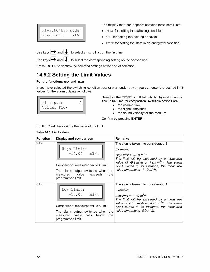
72 IM-EESIFLO-5000V1-EN, 02.03.03
R1=FUNC<typ mode Function: MAX
The display that then appears contains three scroll lists:
• FUNC for setting the switching condition,
• TYP for setting the holding behavior,
• MODE for setting the state in de-energized condition.
Use keys and to select an scroll list on the first line.
Use keys and to select the corresponding setting on the second line.
Press ENTER to confirm the selected settings at the end of selection.
14.5.2 Setting the Limit Values For the functions MAX and MIN
If you have selected the switching condition MAX or MIN under FUNC, you can enter the desired limit values for the alarm outputs as follows:
R1 Input: Volume Flow
Select in the INPUT scroll list which physical quantity should be used for comparison. Available options are:
• the volume flow, • the signal amplitude, • the sound velocity for the medium.
Confirm by pressing ENTER.
EESIFLO will then ask for the value of the limit.
Table 14.5: Limit values
Function Display and comparison Remarks MAX
High Limit: -10.00 m3/h
Comparison: measured value > limit
The alarm output switches when the measured value exceeds the programmed limit.
The sign is taken into consideration!
Example:
High limit = -10.0 m3/h The limit will be exceeded by a measured value of -9.9 m3/h or +2.5 m3/h. The alarm won't switch if, for instance, the measured value amounts to -11.0 m3/h.
MIN
Low Limit: -10.00 m3/h
Comparison: measured value < limit
The alarm output switches when the measured value falls below the programmed limit.
The sign is taken into consideration!
Example:
Low limit = -10.0 m3/h The limit will be exceeded by a measured value of -11.0 m3/h or -22.5 m3/h. The alarm won't switch if, for instance, the measured value amounts to -9.9 m3/h.
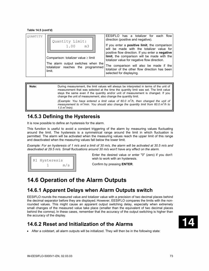
IM-EESIFLO-5000V1-EN, 02.03.03 73
Table 14.5 (cont'd)
QUANTITY
Quantity Limit: 1.00 m3
Comparison: totalizer value ≥ limit
The alarm output switches when the totalalizer reaches the programmed limit.
EESIFLO has a totalizer for each flow direction (positive and negative).
If you enter a positive limit, the comparison will be made with the totalizer value for positive flow direction. If you enter a negative limit, the comparison will be made with the totalizer value for negative flow direction.
The comparison will also be made if the totalizer of the other flow direction has been selected for displaying.
Note: During measurement, the limit values will always be interpreted in terms of the unit of measurement that was selected at the time the quantity limit was set. The limit value stays the same even if the quantity and/or unit of measurement is changed. If you change the unit of measurement, also change the quantity limit. (Example: You have entered a limit value of 60.0 m3/h, then changed the unit of measurement to m3/min. You should also change the quantity limit from 60.0 m3/h to 1.0 m3/min).
14.5.3 Defining the Hysteresis It is now possible to define an hysteresis for the alarm.
This function is useful to avoid a constant triggering of the alarm by measuring values fluctuating around the limit. The hysteresis is a symmetrical range around the limit in which fluctuation is permitted. The alarm will be activated when the measuring values reach the upper limit of this range and deactivated when the measuring values fall below the lower limit.
Example: For an hysteresis of 1 m/s and a limit of 30 m/s, the alarm will be activated at 30.5 m/s and deactivated at 29.5 m/s. Small fluctuations around 30 m/s won't have any effect on the alarm.
R1 Hysteresis 1 m/s
Enter the desired value or enter "0" (zero) if you don't wish to work with an hysteresis.
Confirm by pressing ENTER.
14.6 Operation of the Alarm Outputs 14.6.1 Apparent Delays when Alarm Outputs switch EESIFLO rounds the measured value and totalizer value with a precision of two decimal places behind the decimal separator before they are displayed. However, EESIFLO compares the limits with the non-rounded values. This might cause an apparent output switching delay, especially when extremely small changes of the measured value take place (smaller than the equivalent of two decimal places behind the comma). In these cases, remember that the accuracy of the output switching is higher than the accuracy of the display.
14.6.2 Reset and Initialization of the Alarms • After a coldstart, all alarm outputs will be initialized. They will then be in the following state:

74 IM-EESIFLO-5000V1-EN, 02.03.03
Table 14.6: State of the output after initialization
FUNC: OFF TYPE: NON HOLD MODE: NO CONT. LIMIT: 0.00
• (only in firmware version 5.42 and higher) During measurement, pressing key C three times will switch all alarms to their idle state. However, all alarms which switching condition is still met will switch back into their active state after 1 second. Use this function to reset an alarm of type HOLD when the switching condition is not met anymore.
• Pressing BRK stops measurement and brings you back to the main menu. All alarms are switched to their de-energized state, independently of their programmed idle state.
14.6.3 Alarm Outputs in the Parameter Record The configuration of the alarm outputs will be stored with the current parameter record (program branch SPECIAL FUNCTION). Thus, the configuration of the alarm outputs will also be loaded when a stored parameter record is loaded.
14.6.4 Alarm Outputs during Transducer Positioning When the positioning of the transducers begins (bar graph display), all alarms outputs switch to their programmed idle state.
If you return to the bar graph display during measurement, the alarms will switch back to their programmed idle state. An alarm output of the type HOLDING which has switched during the previous measurement will remain in its programmed idle state after completion of the transducer positioning if the switching condition is not met any more.
You can obtain the same result by pressing key C three times during measurement. The switching of the alarms into their programmed idle state is not indicated on the display.
14.6.5 Alarm Output during Measurement Alarms with switching condition MAX or MIN will be updated once per second at most in order to avoid 'humming' (a permanently fluctuating measured value around the limit constantly triggering the alarm).
Alarms of type NON-HOLD will switch in their activated state for about 1 second when the switching condition is met.
Alarms with switching condition QUANTITY will immediately switch in their activated state when the totalizer value reaches or exceeds the limit.
Alarms with switching condition ERROR will only switch in their activated state after several unsuccessful measuring attempts. Therefore, typical short-term disturbances of the measurement as, for example, air bubble caused by pumps being switched on, will not activate the alarm. If the alarms are of type NON-HOLD, they will switch back as soon as a valid measured value is obtained.
If there is an internal adaptation to changing measuring conditions, e.g. to a considerable rise of the medium temperature, the alarm will not switch.
Alarms with the switching condition OFF will automatically be set to the mode NO CONT. The alarm is de-energized.

IM-EESIFLO-5000V1-EN, 02.03.03 75
Flow+
-
0Alarms with switching condition + - - + (sign change) and type NON-HOLD will switch in their activated state for about 1 second with any change of flow direction.
Alarm Type: NON HOLDING
approx. 1 s
Alarms with switching condition + - - + (sign change) and type HOLD will switch in their activated state with the first change of flow direction and stay in this state. They can be switched back by pressing the key C three times.
Alarm Type: HOLDING
C Manual deactivationof the alarm
Fig. 14.2: Behavior of a relay when the flow direction changes
14.6.6 Alarms' State Note: There are no visual or acoustic indication of alarm switching or resetting.
It is possible to have the state of the alarms displayed during measurement. This function can be activated in program branch SPECIAL FUNCTION \ SYSTEM SETTINGS \ DIALOGS/MENUS. This setting is coldstart resistant.
SHOW RELAIS STAT off >ON<
Select the SHOW RELAIS STAT option. Select ON to activate the display of the alarms' state.
During measurement, press key to scroll on the first line of the display until you reach the alarm's state display.
The alarm's state is displayed in the following form:
RX = , where represents a pictogram (R1 = for example).
The signification of the pictograms is explained in Table 14.7.
14.7 Deactivating the Outputs If you no longer require a programmed output, it can be deactivated. The configuration of the deactivated output is stored and will be available when the output is re-activated.
Alarm Output >NO< yes
Deactivate the outputs by selecting NO in the respective display of the program branch OUTPUT OPTIONS.
Confirm by pressing ENTER.
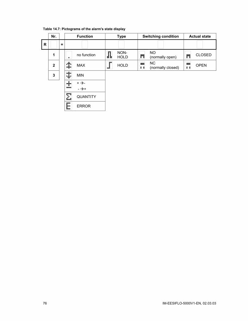
76 IM-EESIFLO-5000V1-EN, 02.03.03
Table 14.7: Pictograms of the alarm's state display
Nr. Function Type Switching condition Actual state
R =
1 no function NON-HOLD
NO (normally open) CLOSED
2 MAX HOLD NC (normally closed) OPEN
3 MIN
+ - - +
QUANTITY
ERROR
IM-EESIFLO-5000V1-EN, 02.03.03 77
15 Troubleshooting First Step: Which of the followings describes the best your problem?
a) The display does not work at all or always goes out.
Make sure that the correct voltage is available at the terminals. The necessary voltage is indicated on the metal plate under the terminal strip where the power supply is connected.
If the power supply is ok, the transducers or an internal component of the transmitter are defective. Send the transmitter and the transducers to EESIFLO for reparation.
b) The message "System Error" is displayed.
Press BRK to return to the main menu.
If this happens several times, note the code displayed on the lower line of the display, write down in which situation the error occurred and contact EESIFLO.
c) The flowmeter doesn't react when BRK is pressed during measurement.
A program code has been defined. Press key C and enter the program code.
d) The backlight of the display does not light on, but everything else works.
The backlight is defective. Send the instrument to EESIFLO for repair. This problem has no influence on the other functions of the display..
e) The date and time displayed are wrong and measured values are deleted when the flowmeter is switched off.
The data backup battery must be replaced. Send the instrument to EESIFLO.
f) A process output doesn't work.
Make sure that the outputs are configurated correctly. Control the function of the output as described in section 14.1.3. If the output is defective, contact EESIFLO.
g) Measurement is impossible or the measured values substantially differ from the expected values.
See section 15.1.
h) The totalizer values are wrong.
See section 15.6.
If any problem appears which cannot be solved with the help of this chapter, please contact EESIFLO, giving a precise description of the problem. Don't forget to specify the model, serial number and firmware version of your instrument.
Calibration
EESIFLO is a very reliable instrument. It is manufactured under strict quality control, using modern production techniques. If installed as recommended in an appropriate location, used cautiously and taken care of conscientiously, no troubles should appear. The instrument has been calibrated at the factory and usually, a re-calibration of the flowmeter won't be necessary.
However, a new calibration might be advisable if
• the surface of the transducers show visible wear
• or if the transducer were used for a prolonged period at a high temperature (many months at a temperature of more than 130°C for normal transducers or of more than 200°C for high temperature transducers).
In this case, the instrument will have to be sent to EESIFLO for calibration under reference conditions.
78 IM-EESIFLO-5000V1-EN, 02.03.03
15.1 Problems with the Measurement a) Measurement is impossible because no signal can be detected. A question mark appears at
the right side of the lower display line.
• First of all, make sure that the entered parameter are correct, especially the outer diameter of the pipe, the wall thickness and the sound velocity.
(Typical errors: the circumference or the radius was entered instead of the diameter. The inner diameter was entered instead of the outer diameter).
• Make sure that the transducer distance recommended by EESIFLO was respected when mounting the transducers.
• Make sure that the selected measuring point is adequate. See section 15.2.
• Try to obtain better acoustic contact between the pipe and the transducers. See section 15.3.
• Try to measure with a smaller number of transit paths. The signal attenuation might be too high because of a high fluid viscosity or of the presence of deposits on the inner pipe wall.
• See section 15.4 "Application Specific Problems".
b) The measuring signal was found but no measuring value can be obtained.
If an exclamation mark "!" is displayed at the right of the measuring units, the measured values are greater than the velocity limit and are thus invalid. The velocity limit should be adapted to the measuring situation or the velocity check should be deactivated (velocity limit = 0).
If no exclamation mark "!" is displayed: Measurement is fundamentally impossible at the selected measuring point.
c) Loss of Signal during Measurement
• Did the pipe run empty and then filled up again? In this case, consult EESIFLO.
Wait a little while until the acoustic contact is established again. There might be a temporary higher proportion of gaseous or solid particles in the flowing medium. If measurement does not resume, proceed as described in a).
d) Measuring values substantially differ from the expected values.
Wrong measuring values are often caused by false parameters. Make sure the parameters entered are correct for the point at which you are measuring.
If the parameters are OK, refer to section 15.5. It describes some typical situations in which wrong measuring values are obtained.
15.2 Correct Selection of the Measuring Point • Make sure that the recommended straight pipe run to any disturbance source is respected. See
Table 6.1.
• When measuring on horizontal pipes, the transducers should be mounted on the side of the pipes. Avoid locations where deposits are building in the pipe.
• The pipe should always be filled at the measuring point, and the liquid must flow upward.
• No bubbles should accumulate (even bubble-free liquids can form gas pockets at places where the liquid expands, e.g. especially behind pumps and where the cross-sectional area of the pipe extends considerably).
• Avoid measuring points in the vicinity of deformations and defects of the pipe or in the vicinity of weldings.
• Measure the temperature at the measuring point and make sure that the transducer used are adequate for this temperature.
IM-EESIFLO-5000V1-EN, 02.03.03 79
Note: If the temperature at the measuring point is fluctuating, it is very important that the two inner hooks of the clasp are engaged in the tension strap. Otherwise, the pressure on the transducer will be insufficient when the temperature goes down. In case of strong temperature fluctuations, it is recommended to work with the special EESIFLO tensions straps with integrated spring which will compensate the diameter fluctuation caused by thermal expansion.
• Make sure that the pipe diameter is in the measuring range of the transducers.
15.3 Maximum Acoustic Contact In order to obtain maximum acoustic contact between the pipe and the transducers, pay attention to the following points:
• The pipe must be clean and free of loose paint or corrosion.
Rust or other deposits absorb the acoustic signals. Clean the pipe at the selected measuring point. Remove rust or loose paint.
• Grind off any thick layer of paint.
• Always apply a bead of acoustic coupling compound lengthwise down the center of the contact surface of the transducers.
• Make sure that the mounting fixtures applies the necessary pressure on the transducers. There should be no air pockets between transducer surface and pipe wall.
15.4 Application Specific Problems Possible problem: The entered sound velocity might be wrong. The sound velocity is used by the flowmeter to determine the transducer distance and is therefore very important for transducer positioning. The sound velocities programmed in the flowmeter should only serve as orientation values. It might be necessary to have the sound velocity of the medium measured.
Possible problem: The value entered for the pipe roughness might be inappropriate. Reconsider the entered value, taking into account the state of the pipe.
Possible problem: Measurements on porous pipe materials (e.g. concrete or cast iron) are only possible under certain conditions. Consult EESIFLO.
Possible problem: Lined pipes might cause problem if the lining is not bonded correctly to the pipe wall or consists of a material which has bad acoustic characteristics. Try measuring on a linerfree section of the pipework.
Possible problem: Media with high viscosity strongly attenuate the ultrasonic signals. Measurements on media with viscosity higher than 1000 mm2/s are only possible under certain conditions.
Possible problem: Particles scatter and absorb ultrasounds and therefore attenuate the signal. Measurement is hardly possible if the proportion of solid particles or gas bubbles is of 10% or more. If the latter is high, but less than 10%, measurements might be possible under certain conditions.
Possible problem: The flow might be in the transition range between laminar and turbulent flow where flow measurement is problematic. Check the Reynolds number of the flow at the measuring point using FluxFlow and consult EESIFLO.
15.5 Measurement Data Substantially Differs from the Expected Value
Possible causes for wrong measured values:
• A wrong sound velocity for the medium.
A wrong value of the sound velocity could lead the user to identify the ultrasonic signal that was reflected on the pipe wall and did not cross the medium as the measuring signal. The measured flow rate will then be very small or fluctuate around zero.

80 IM-EESIFLO-5000V1-EN, 02.03.03
• There is gas in the pipe.
If there is gas in the pipe, the measured volume flow rate will always be too high, since both the gas volume and the medium volume are being measured.
• The upper limit for the flow velocity is too low.
The measured flow velocities that are greater than the defined upper limit are ignored and marked as outlier. All quantities derived from the flow velocity are equally ignored. If a certain number of correct measuring values are higher than the limit, the totalized values (the volume flow rate for example) will be too small.
• The defined cut-off flow is too high.
All flow velocities below the cut-off are set to zero, as well as all quantities derived from these flow velocities. To measure small flow velocities, the cut-off flow (default value 5 cm/s) must be set to an appropriate value.
• The pipe roughness is inappropriate.
• The flow velocity to be measured is outside the measuring range of the transducers.
• The measuring point is inadequate.
Try measuring somewhere else on the pipework and see if the results are better. Pipes are never perfectly round and this influences the flow profile. Try modifying the position of the transducers relative to the deformation of the pipe.
15.6 Problem with the Totalizers • If the totalizer values are too big:
Check SPECIAL FUNCTIONS\SYSTEM SETTINGS\MEASURING\QUANTITY RECALL.
If this option is activated, the totalizer value of a measurement is saved. The totalizer will take this value at the start of the next measurement.
• If the totalizer values are too small:
One of the totalizers might have reached the internal limit. It must be reset to zero manually.
• If the output of the sum of the totalizers is not correct:
Check SPECIAL FUNCTIONS\SYSTEM SETTINGS\MEASURING\QUANT. WRAPPING.
The output of the sum of both totalizers via a process output is not valid after the first overflow (wrapping) of one of the respective totalizers.
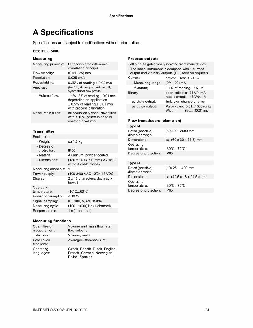
Specifications
IM-EESIFLO-5000V1-EN, 02.03.03 81
A Specifications Specifications are subject to modifications without prior notice.
EESIFLO 5000
Measuring Measuring principle: Ultrasonic time difference
correlation principle Flow velocity: (0.01...25) m/s Resolution: 0.025 cm/s Repeatability: 0.25% of reading ± 0.02 m/s Accuracy (for fully developed, rotationally
symmetrical flow profile) - Volume flow: ± 1% ..3% of reading ± 0.01 m/s
depending on application ± 0.5% of reading ± 0.01 m/s with process calibration
Measurable fluids: all acoustically conductive fluids with < 10% gaseous or solid content in volume
Transmitter Enclosure - Weight: ca 1.5 kg - Degree of protection:
IP66
- Material: Aluminum, powder coated - Dimensions: (180 x 140 x 71) mm (WxHxD)
without cable glands Measuring channels: 1 Power supply: (100-240) VAC 12/24/48 VDC Display: 2 x 16 characters, dot matrix,
backlit Operating temperature:
-10°C...60°C
Power consumption: < 10 W Signal damping: (0...100) s, adjustable Measuring cycle: (100...1000) Hz (1 channel) Response time: 1 s (1 channel) Measuring functions Quantities of measurement:
Volume and mass flow rate, flow velocity
Totalizers: Volume, mass Calculation functions:
Average/Difference/Sum
Operating languages:
Czech, Danish, Dutch, English, French, German, Norwegian, Polish, Spanish
Process outputs - all outputs galvanically isolated from main device - The basic instrument is equipped with 1 current
output and 2 binary outputs (OC, reed on request). Current active: Rext < 500 Ω - Measuring range: (0/4...20) mA - Accuracy: 0.1% of reading ± 15 µA Binary open collector: 24 V/4 mA
reed contact: 48 V/0.1 A as state output: limit, sign change or error as pulse output: Pulse value: (0.01...1000) units
Width: (80...1000) ms Flow transducers (clamp-on) Type M Rated (possible) diameter range:
(50)100...2500 mm
Dimensions: ca. (60 x 30 x 33.5) mm Operating temperature:
-30°C...70°C
Degree of protection: IP65 Type Q Rated (possible) diameter range:
(10) 25 ... 400 mm
Dimensions: ca. (42.5 x 18 x 21.5) mm Operating temperature:
-30°C...70°C
Degree of protection: IP65
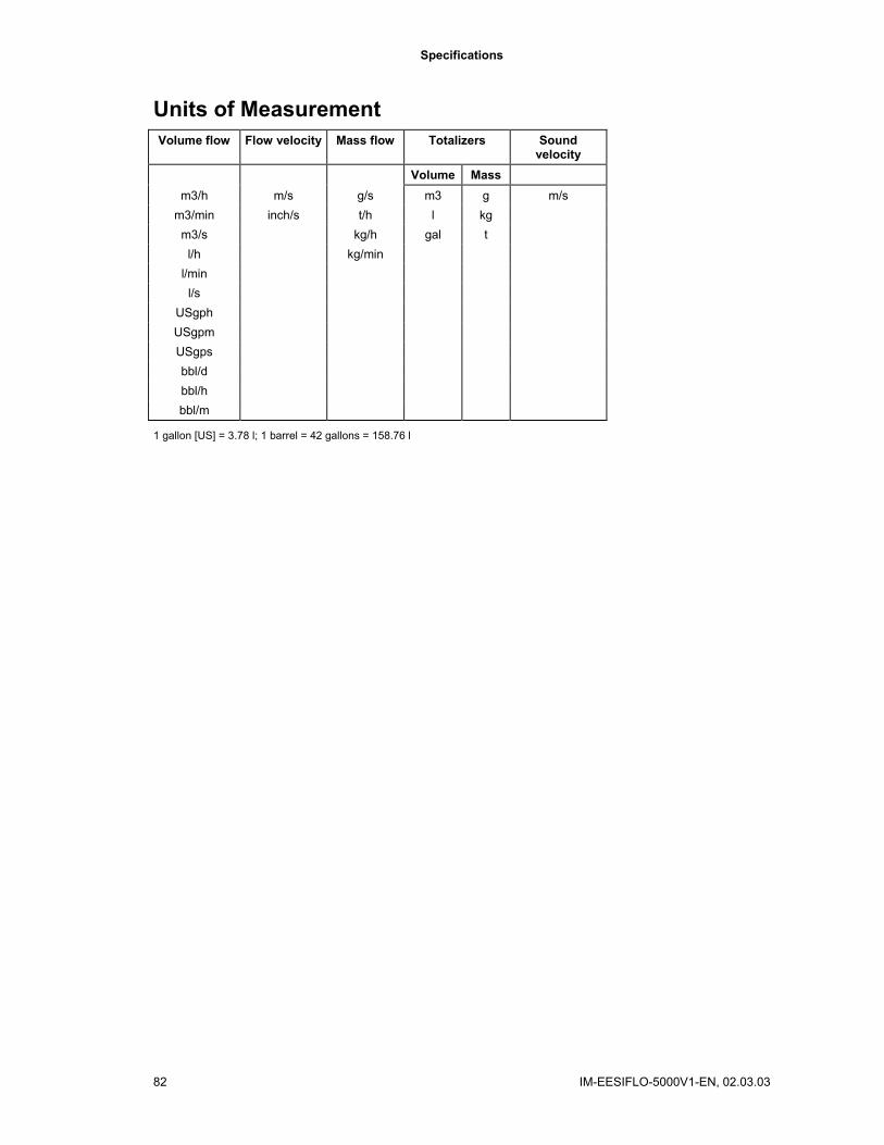
Specifications
82 IM-EESIFLO-5000V1-EN, 02.03.03
Units of Measurement Volume flow Flow velocity Mass flow Totalizers Sound
velocity Volume Mass
m3/h m/s g/s m3 g m/s m3/min inch/s t/h l kg
m3/s kg/h gal t l/h kg/min
l/min l/s
USgph USgpm USgps bbl/d bbl/h bbl/m
1 gallon [US] = 3.78 l; 1 barrel = 42 gallons = 158.76 l
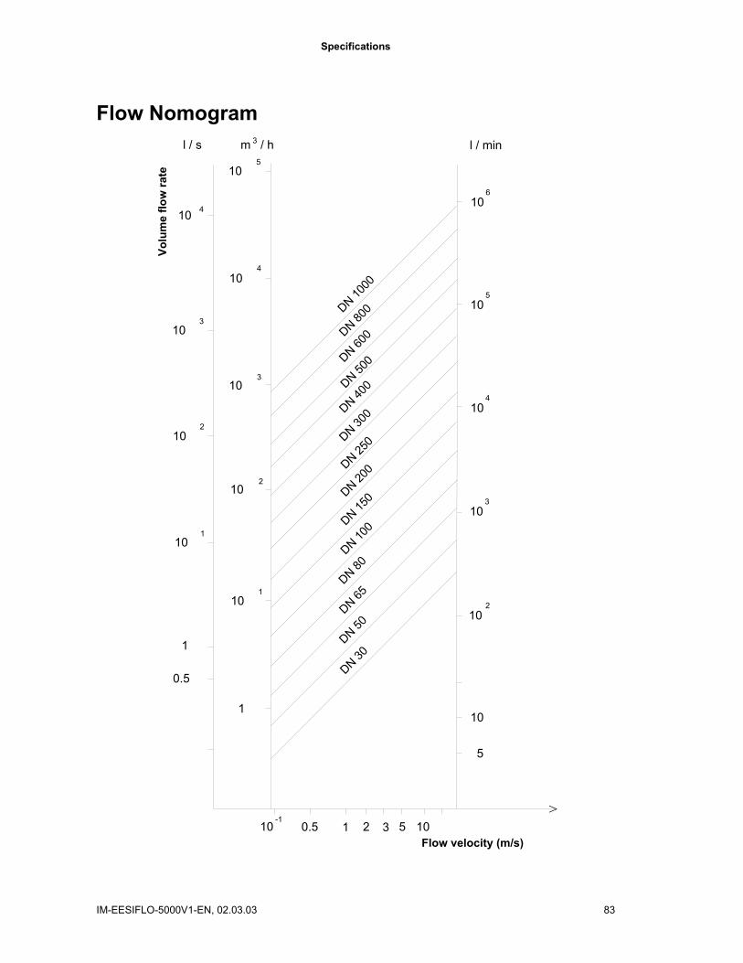
Specifications
IM-EESIFLO-5000V1-EN, 02.03.03 83
Flow Nomogram
10
5
1
1
0.5
l / minl / s
Flow velocity (m/s)
DN 800DN 10
00
DN 600
DN 500
DN 300DN 40
0
DN 200DN 25
0
DN 100DN 15
0
DN 50DN 65
DN 80DN 30
0.5 3 1052110-1
3m / h
>
10 4
310
10 2
10 1
10 5
10 4
310
10 2
10 1
106
10 5
104
103
102
Volu
me
flow
rate

Specifications
84 IM-EESIFLO-5000V1-EN, 02.03.03

Overview of the Firmware
IM-EESIFLO-5000V1-EN, 02.03.03 85
B Overview of the Firmware
Spec
ial F
unct
ion
(con
t'd)
Dialogs/Menus
Pipe Circumfer. On/Off
Fluid Pressure On/Off
Meas. Point No. 1234/<-->
Sound Path Auto/User
Transd. Distance Auto/User
Steam in inlet On/Off
Time-progr. Meas. On/Off
Error-val. delay Edit/Damp.
Show relais stat On/Off
Measuring
Flow Velocity Normal/Uncor
Cut-Off Flow Sign/Absolute
Cut-Off Flow User/Factory
Cut-Off Flow
Velocity limit
Heat Quantity
Heat+flow quant. On/Off
Quant. wrapping On/Off
Quantity recall On/Off
Spec
ial F
unct
ion
System Settings
Proc. Outputs
Install Output
Source channel
Source item
Output range
Output MIN
Output MAX
Error-value
Storing
Storage Mode sample/average
Quantity Storage one/both
Store Amplitude on/off
Store c-Medium on/off
Serial Transmiss.
kill spaces
decimalpoint
col-separat.
Libraries
Material list factory/user
Medium list factory/user
Format USER-AREA
Materials:
Media:
Heat-Coeffs:
Steam-Coeffs:
Concentrat:
Extended Library On/Off
Out
put O
ptio
ns
Channel
Physical Quantity
Unit
Temperature T1
Temperature T2
Damping
Store Meas. Data No/Yes
Serial Output No/Yes
Storage Rate
Current Loop I#
Zero-Scale Val.
Full-Scale Val.
Error-value delay
Voltage Output U#
Zero-Scale Val.
Full-Scale Val.
Error-value delay
Frequency Output F1
Zero-Scale Val.
Full-Scale Val.
Error-value delay
Alarm Output R#
FUNC:
TYPE:
MODE:
R1 Input
High Limit
Low Limit
Quantity limit
Hysterese
Pulse Output
Pulse Value
Pulse Width
Mea
surin
g
Time-prog. Meas.
Meas. Point No.
Profile corr.?
Sound Path
Transd. Distance
Para
met
er
Channel
Parameter from:
Outer diameter
Wall Thickness
Pipe material
c-Material
Liner
Liner material
c-Material
Liner thickness
Roughness
Medium
c-Medium MIN
c-Medium MAX
Kin. viscosity
Density
Temperature
Pressure
TransducerType
Transd. data
Additional cable
Ove
rvie
w o
f the
Firm
war
e (V
5.XX
) A
ttent
ion:
The
men
u op
tions
des
crib
ed in
gra
y ce
lls a
re n
ot n
eces
saril
y ac
tivat
ed!

Overview of the Firmware
86 IM-EESIFLO-5000V1-EN, 02.03.03
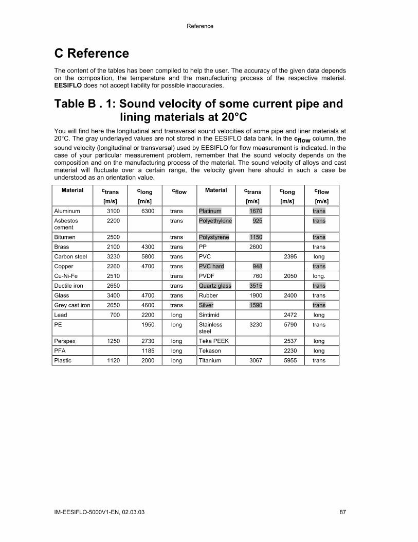
Reference
IM-EESIFLO-5000V1-EN, 02.03.03 87
C Reference The content of the tables has been compiled to help the user. The accuracy of the given data depends on the composition, the temperature and the manufacturing process of the respective material. EESIFLO does not accept liability for possible inaccuracies.
Table B . 1: Sound velocity of some current pipe and lining materials at 20°C
You will find here the longitudinal and transversal sound velocities of some pipe and liner materials at 20°C. The gray underlayed values are not stored in the EESIFLO data bank. In the cflow column, the sound velocity (longitudinal or transversal) used by EESIFLO for flow measurement is indicated. In the case of your particular measurement problem, remember that the sound velocity depends on the composition and on the manufacturing process of the material. The sound velocity of alloys and cast material will fluctuate over a certain range, the velocity given here should in such a case be understood as an orientation value.
Material ctrans [m/s]
clong
[m/s]
cflow
Material ctrans [m/s]
clong [m/s]
cflow
[m/s] Aluminum 3100 6300 trans Platinum 1670 trans
Asbestos cement
2200 trans Polyethylene 925 trans
Bitumen 2500 trans Polystyrene 1150 trans
Brass 2100 4300 trans PP 2600 trans
Carbon steel 3230 5800 trans PVC 2395 long
Copper 2260 4700 trans PVC hard 948 trans
Cu-Ni-Fe 2510 trans PVDF 760 2050 long.
Ductile iron 2650 trans Quartz glass 3515 trans
Glass 3400 4700 trans Rubber 1900 2400 trans
Grey cast iron 2650 4600 trans Silver 1590 trans
Lead 700 2200 long Sintimid 2472 long
PE 1950 long Stainless steel
3230 5790 trans
Perspex 1250 2730 long Teka PEEK 2537 long
PFA 1185 long Tekason 2230 long
Plastic 1120 2000 long Titanium 3067 5955 trans

Reference
88 IM-EESIFLO-5000V1-EN, 02.03.03
Table B . 2: Typical roughness coefficients for pipes For your convenience, we have already pre-programmed common roughness coefficients for pipe materials. The data are based upon experience with measurements performed with these pipe materials.
Pipe wall material Absolute roughness [µm]
Pipe wall material Absolute roughness [µm]
Drawn pipes of non-ferrous metal, glass, plastics and light metal
0 ... 1.5 Cast iron pipes
Drawn steel pipes 10 ... 50 • bitumen lining 120 ... fine-planed, polished surface up to ... 10 • new, without lining 250 ... 1000
planed surface 10 ... 40 • rusted 1000 ... 1500 rough-planed surface 50 ... 100 • encrusted 1500 ... 3000
Welded steel pipes, new 50 ... 100 long usage, cleaned 150 ... 200 lightly and evenly rusted up to ... 400 heavily encrusted up to ... 3,000
Table B . 3: Typical properties of media at T=20°C and p=1 bar
Medium Sound velocity [m/s] Kinematic viscosity [mm2/s]
Density [g/cm3]
30% Glycol / H2O 1671 4.0 1.045 50% Glycol / H2O 1704 6.0 1.074 80% Sulphuric acid 1500 3.0 1.700 96% Sulphuric acid 1500 4.0 1.840 Acetone 1190 0.4 0.790 Ammonia 1660 1.0 0.800 Petrol 1295 0.7 0.880 BP Transcal LT 1415 13.9 0.740 BP Transcal N 1420 73.7 0.750 CaCl2 -15 C 1900 3.2 1.170 CaCl2 -45 C 2000 19.8 1.200 Cerium solution 1570 1.0 1.000 Ethyl ether 1600 0.3 0.716 Glycol 1540 17.7 1.260 H2O-Ethan.-Glyc. 1703 6.0 1.000 HLP32 1487 77.6 0.869 HLP46 1487 113.8 0.873 HLP68 1487 168.2 0.875 ISO VG 22 1487 50.2 0.869 ISO VG 32 1487 78.0 0.869 ISO VG 46 1487 126.7 0.873 ISO VG 68 1487 201.8 0.875 ISO VG 100 1487 314.2 0.869 ISO VG 150 1487 539.0 0.869 ISO VG 220 1487 811.1 0.869 Copper sulphate 1550 1.0 1.000 Methanol 1121 0.8 0.791

Reference
IM-EESIFLO-5000V1-EN, 02.03.03 89
Medium Sound velocity [m/s] Kinematic viscosity [mm2/s]
Density [g/cm3]
Milk 0.3% fat 1511 1.5 1.030 Milk 1.5% fat 1511 1.6 1.030 Milk 3.5% fat 1511 1.7 1.030 Oil 1740 344.8 0.870 Quintolubric 200 1487 69.9 0.900 Quintolubric 300 1487 124.7 0.920 R134 Freon 526 1.0 1.000 R22 Freon 563 1.0 1.000 Hydrochloride acid 37% 1520 1.7 1.200 Sour cream 1550 50.0 1.000 Shell Thermina B 1458 74.5 0.863 SKYDROL 500-B4 1387 21.9 1.057 Toluene 1305 0.6 0.861 Vinyl chloride 900 --- 0.970 Water 1482 1.0 0.999 Zinc powder suspension 1580 1.0 1.000 Tin chloride suspension 1580 1.0 1.000
Table B . 4: Chemical resistance of Autotex (keypad) Autotex is resistant (acc. to DIN 42 115, part 2) to following chemicals for a contact time of more than 24 hours without visible modification:
Ethanol Formaldehyde 37%-42% 1,1,1-Trichlorethane Cyclohexanol Acetaldehyde Ethyl acetate Diacetone alcohol Aliphatic hydrocarbons Diethyl ether Glycol Toluol N-butyl acetate Isopropanol Xylol Amyl acetate Glycerine Diluent (white spirit) Butylcellosolve Methanol Ether Triacetin Dowandol DRM/PM Acetone Formic acid <50% Chlornatron <20% Methyl-ethyl-ketone Acetic acid <50% Hydrogen peroxide<25% Dioxan Phosphoric acid <30% Potash soft soap Cyclohexanone Hydrochloric acid <36% Detergent MIBK Nitric acid <10% Tensides Isophorone Trichloroacetic acid <50% Softener Sulphuric acid <10% Iron chlorides (FeCl2) Ammonia <40% Drilling emulsion Plane fuel Iron chlorides (FeCl3) Soda lye <40% Diesel oil Gasoline Dibutyl Phthalat Potassium hydroxide <30% Varnish Water Dioctyl Phthalat Alcalicarbonate Paraffin oil Salted water Sodium carbonate Bichromate Castor oil Potassium hexacyanoferrates Silicone oil Acetonitrile Turpentine oil
substitute
Sodium bisulfate Dccon
Autotex is resistant (acc. to DIN 42 115, part 2) to acetic acid for a contact time of less than 1 hour without visible damage.
Autotex is not resistant to following chemicals:
Concentrated mineral acids Benzyl alcohol Concentrated alkaline solutions Methylene chloride High pressure steam over 100°C

Reference
90 IM-EESIFLO-5000V1-EN, 02.03.03
Table B . 5: Properties of water with pressure p = 1 bar and saturation
T (°C) p (bar) ρ (kg m-3) cP (kJ kg-1 K-1)
0 1 999.8 4.218 10 1 999.7 4.192 20 1 998.3 4.182 30 1 995.7 4.178 40 1 992.3 4.178 50 1 988.0 4.181 60 1 983.2 4.184 70 1 977.7 4.190 80 1 971.6 4.196 90 1 965.2 4.205
100 1.013 958.1 4.216 120 1.985 942.9 4.245 140 3.614 925.8 4.285 160 6.181 907.3 4.339 180 10.027 886.9 4.408 200 15.55 864.7 4.497 220 23.20 840.3 4.613 240 33.48 813.6 4.769 260 46.94 784.0 4.983 280 64.20 750.5 5.290 300 85.93 712.2 5.762 320 112.89 666.9 6.565 340 146.05 610.2 8.233 360 186.75 527.5 14.58 374.15 221.20 315.5 ∞
T Temperature p Pressure
ρ Density
cp Specific heat at constant pressure

IM-EESIFLO-5000V1-EN, 02.03.03 91
Index Access code........................................................... 41 Alarm outputs ......................................................... 71
limit values......................................................... 72 Alarms' state .......................................................... 75 Applications.............................................................. 6 Cleaning ................................................................... 9 Clock, setting.......................................................... 53 Coefficient storage ................................................. 45 Coldstart................................................................. 15 Contrast, setting..................................................... 57 Cut-off flow............................................................. 39 Damping factor....................................................... 37 Date, setting ........................................................... 53 Density of the medium ........................................... 28 Description of the flowmeter ................................ 5, 7 Display ................................................................... 35 Disturbances .......................................................... 21 Error value.............................................................. 66 Error value delay.................................................... 69 Extended library function ....................................... 47 Firmware ................................................................ 85 Firmware version ................................................... 57 Flow direction......................................................... 34 Flow profile............................................................. 21 Flow velocity
lower limit........................................................... 39 upper limit .......................................................... 39
Handling precautions ............................................... 9 Hot Codes .............................................................. 17 Initialization ............................................................ 15 Input of numerical values....................................... 16 Input of text ............................................................ 16 Instrument information ........................................... 57 Keyboard................................................................ 15 Kinematic viscosity................................................. 28 Language selection................................................ 18 Libraries ................................................................. 43 Main menu ............................................................. 16 Maintenance............................................................. 9 Material list ............................................................. 43 Materials
defining .............................................................. 45 deleting .............................................................. 52 input of the properties.................................. 48, 49
Measurement starting ............................................................... 34 stopping ............................................................. 34
Measuring point examples ........................................................... 23 selection............................................................. 21
Measuring principle.................................................. 5 Media
defining .............................................................. 45 deleting .............................................................. 52 input of the properties.................................. 48, 51
Medium list ............................................................. 43 Medium parameters, input ..................................... 27 Multiplexer.............................................................. 34 Output range .......................................................... 66 Outputs................................................................... 65 Pipe circumference ................................................ 25
Pipe lining ...............................................................26 Pipe lining thickness...............................................27 Pipe material...........................................................26 Pipe outer diameter ................................................25 Pipe parameters, input ...........................................25 Pipe roughness.......................................................27 Process outputs......................................................65
activating a pulse output ....................................70 activating an alarm output..................................71 activating an analogue output............................69 alarms' state.......................................................75 circuits ................................................................14 configuration.......................................................65 error value ..........................................................66 error value delay ................................................69 function check ....................................................68 output range .......................................................66 output value in case of error ..............................66
Program branches..................................................16 Program code .........................................................41 Protection against interruption ...............................41 Quantity of measurement, selection ......................35 Reference ...............................................................87 Reset ......................................................................15 Safety precautions....................................................3 Scope of delivery......................................................9 Selection lists, edition.............................................43 Serial number .....................................................8, 57 Settings
dialogues and menus.........................................54 measurement .....................................................56
Sound path factor ...................................................29 Sound velocity measurement..................................61 Sound velocity of the material ................................27 Sound velocity of the medium................................28 Specifications .........................................................81 Start-up ...................................................................15 SuperUser mode ....................................................59 Tables .....................................................................87 Temperature of the medium...................................28 Text, input ...............................................................16 Time, setting ...........................................................53 Totalizer ..................................................................37 Totalizers
overflow..............................................................38 Transducer distance, display .................................36 Transducer parameters ..........................................29 Transducers..............................................................8
distance between transducers...........................30 positioning ..........................................................33
Transit path.............................................................29 Troubleshooting......................................................77 Uncorrected flow velocity .......................................40 Unit of measurement ..............................................35 User area, partitioning ............................................45 User materials ........................................................45 User media .............................................................45 Velocity limit............................................................39 Wall thickness.........................................................26 Warranty ...................................................................3

1
Certificate No. SG06/00724
EESIFLO International Pte Ltd 60 Kaki Bukit Place #02-19 Eunos TechPark Singapore 415979
65-6748-6911 65-6748-6912 Website: www.eesiflo.com
Measuring Worldwide Certificate No. US06/0478.2
LIMITED WARRANTY This Limited Warranty gives the buyer specific legal rights that vary from country to country. For a period of three hundred sixty-five (365) days from the date of shipment, EESIFLO (hereinafter Seller) warrants the goods manufacture by Seller to be free from defect in material and workmanship to the original purchaser. For a period of ninety (90) days from the date of shipment, Seller warrants the soft goods (seals) installed in Seller’s manufactured equipment to be free from detects and workmanship to the original purchaser. During the warranty period, Seller agrees to repair or replace defective goods or parts without charge for material and labour*. Buyer’s exclusive remedy is repair or replacement of defective goods or, at Seller’s option, return of the goods and credit toward next purchase of the original purchase price. Seller excludes and disclaims any liability for lost profits, personal injury, interruption of service, or for consequential, incidental or special damages arising out of, resulting from, or relating in any manner to these goods. This Limited Warranty does not cover defects, damage or nonconformity resulting from abuse, misuse (operating conditions beyond design scope), neglect, misapplication (failure of Buyer to disclose all service specifications relevant to application), lack of reasonable care, modification or the attachment of improper devices to the goods. This Limited Warranty does not cover goods manufactured by others and incorporated in goods manufactured by Seller. This Limited Warranty does not cover incorporation of future product developments. This warranty is VOID when repairs are performed by a non-authorised service centre or representative. If you have any problems locating an authorised service centre or representative, please call or write to: Eesiflo International Pte Ltd Customer Service Centre No. 60 Kaki Bukit Place #02-19 Eunos Techpark Singapore 415979 Tel: (+65) 6748 6911 Fax: (+65) 6748 6912 At Seller’s option, repair or replacements will be made on site or at factory. If repairs or replacements are to be made at the factory, Buyer shall return the goods prepaid and bear all risks of loss until delivered to the factory. If Seller returns the goods, they will be delivered prepaid and Seller will bear all risk of loss until delivered to Buyer. This Limited Warranty shall be governed by and constructed in accordance with the laws of the State of Singapore. The warranties contained in this agreement are in lieu of all other warranties expressed or implied, including the warranties of merchantability and fitness of a particular purpose. This Limited Warranty supersedes all prior proposals, representations or agreements, oral or written, regarding warranties, and constitutes the entire understanding regarding the warranties made by Seller to Buyer. This Limited Warranty may not be expanded or modified except by a written agreement signed by the Seller. * Labour, defined as in-house labour cost.
Action Policy As related to the EESIFLO Limited Warranty
• Prior to any work or action on EESIFLO manufactured equipment, the warranty claim must be reported to
EESIFLO • The EESIFLO warranty is responsibility of EESIFLO, and EESIFLO will not be responsible for action taken
by any party without EESIFLO’s advice and/or confirmation. Any actions taken without advice and/or confirmation will VIOD the warranty.
• Any warranty action taken without EESIFLO’s direction shall be the sole responsibility and risk of the party taking the action.
• If shipment of any goods under warranty is necessary, EESIFLO will be responsible for normal shipping costs. All expedited shipping costs are the customer’s responsibility unless confirmed in writing by EESIFLO.
• EESIFLO may, at its discretion, direct warranty work for EESIFLO manufactured equipment to a facility other than its factory. This action can only be authorised and directed by EESIFLO.
• EESIFLO reserves the right to replace a defective item or part, rather than repairing the original item or part.
• EESIFLO does not warrant goods manufactured by other companies. Those items carry warranty coverage from the manufacturer, and claims must be made to those companies directly by the purchaser.
Related Documents