PL-TR-95-1114 PL-TR- 95-1114 500 WATT SOLAR AMTEC POWER SYSTEM FOR SMALL SPACECRAFT Joseph F. Ivanenok, III Robert K. Sievers Advanced Modular Power Systems, Inc. 4667 Freedom Drive Ann Arbor, MI 48108 March 1995 Final Report WARNING - This document contains technical data whose iexport is restricted by the Arms Export Control Act (Title -biato March 1995, Other requests for this document 2.U.C.Se271 .)oThExrtAmntaio InUbrfo r edtonCST Act of 1979, as amended (Title 50, U.S.C.. App. 2401, et g4 Violations of these export laws are subject to severe criminal penalties. Disseminate lAW the provisions of DoD Directive 5230.25 and AFi t 61204. DES"TRUITON NOTICE.- For classified documents, follow the procedures in DoD) 5200.22-M, Industrial Security Manual, 'Section 11-19 or Dot) 5200.1-P, Information Security Program Regulation, Chapter TX, For unclassified, limited documents,1 dJestroy by any method that will prevent disclosure of contents or reconstruction of the document 19961029 063 PHILLIPS LABORATORY Space and Missiles Technology Directorate AIR FORCE MATERIEL COMMAND KIRTLAND AIR FORCE BASE, NM 87117-5776

Welcome message from author
This document is posted to help you gain knowledge. Please leave a comment to let me know what you think about it! Share it to your friends and learn new things together.
Transcript
PL-TR-95-1114 PL-TR-95-1114
500 WATT SOLAR AMTEC POWER SYSTEM FORSMALL SPACECRAFT
Joseph F. Ivanenok, IIIRobert K. Sievers
Advanced Modular Power Systems, Inc.4667 Freedom DriveAnn Arbor, MI 48108
March 1995
Final Report
WARNING - This document contains technical data whoseiexport is restricted by the Arms Export Control Act (Title
-biato March 1995, Other requests for this document 2.U.C.Se271 .)oThExrtAmntaioInUbrfo r edtonCST Act of 1979, as amended (Title 50, U.S.C.. App. 2401, etg4 Violations of these export laws are subject to severe
criminal penalties. Disseminate lAW the provisions of DoDDirective 5230.25 and AFi t 61204.
DES"TRUITON NOTICE.- For classified documents, follow the procedures in DoD) 5200.22-M, Industrial Security Manual,'Section 11-19 or Dot) 5200.1-P, Information Security Program Regulation, Chapter TX, For unclassified, limited documents,1
dJestroy by any method that will prevent disclosure of contents or reconstruction of the document
19961029 063PHILLIPS LABORATORYSpace and Missiles Technology DirectorateAIR FORCE MATERIEL COMMANDKIRTLAND AIR FORCE BASE, NM 87117-5776
U IN CLASII- ILL)
AD NUMBER
NEW LIMITATION CHANGETO DISTRIBUTION STATEMENT A -
Approved for public release; Distri-bution unlimited.
Limitation Code: 1
FROMDISTRIBUTION STATEMENT -
Limitation Code:
AUTHORITY
Jc_.4- L. KMopsVr Ph,1I1p Lab/A, K,_ivaiond u,
THIS PAGE IS UNCLASSIFIED
PL-TR-95-1114
Using Government drawings, specifications, or other data included in this document for anypurpose-other than Government procurement does not in any way obligate the U.S. Government.The fact that the Government formulated or supplied the drawings, specifications, or other data,does not license the holder or any other person or corporation; or convey any rights or permissionto manufacture, use, or sell any patented invention that may relate to them.
This report contains proprietary information and shall not be either released outside thegovernment, or used, duplicated or disclosed in whole or in part for manufacture orprocurement, without the written permission of the contractor. This legend shall be markedon any reproduction hereof in whole or in part.
If'you change your address, wish to be removed from this mailing list, or your organization nolonger employs the addressee, please notify PL/VTP, 3550 Aberdeen Ave SE, Kirtland AFB, NM87117-5776.
Do not return copies of this report unless contractual obligations or notice on a specific documentrequires its return.
This report has been approved for publication.
MICHAEL SCHULLER, GS-13
Project Manager
FOR THE COMMANDER
PAUL L. THEE, Maj, USAF CHRISTINE M. ANDERSONChief, Space Power & Thermal Director, Space and Missiles TechnologyManagement Division Directorate
The following notice applies to any unclassified (including originally classifiedand now declassified) technical reports released to "qualified U.S. contractors"under the provisions of DoD Directive 5230.25, Withholding of UnclassifiedTechnical Data From Public Disclosure.
NOTICE TO ACCOMPANY THE DISSEMINATION OF EXPORT-CONTROLLED TECHNICAL DATA
1. Export of information contained herein, which includes, in somecircumstances, release to foreign nationals within the United States, withoutfirst obtaining approva, or license from the Department of State for itemscontrolled by the International Traffic in Arms Regulations (ITAR), or theDepartment of Commerce for items controlled by the Export AdministrationRegulations (EAR), may constitute a violation of law.
2. Under 22 U.S.C. 2778 the penalty for unlawful export of items or informationcontrolled under the ITAR is up to two years imprisonment, or a fine of $100,000,or both. Under 50 U.S.C., Appendix 2410, the penalty for unlawful export ofitems or information controlled under the EAR is a fine of up to $1,000,000, orfive times the value of the exports, whichever is greater; or for an individual,imprisonment of up to 10 years, or a fine f up to $250,000, or both.
3. In accordance with your certification that establishes you as a "qualifiedU.S. Contractor", unauthorized dissemination of this information is prohibitedand may result in disqualification as a qualified U.S. contractor, and may beconsidered in determining your eligibility for future contracts with theDepartment of Defense.
4. The U.S. Government assumes no liability for direct patent infringement, orcontributory patent infringement or misuse of technical data.
5. The U.S. Government does not warrant the adequacy, accuracy, currency, orcompleteness of the technical data.
6. The U.S. Government assumes no liability for loss, damage, or injuryresulting from manufacture or use for any purpose of any product, article,system, or material involving reliance upon any or all technical data furnishedin response to the request for technical data.
7. If the technical data furnished by the Government will be used for commercialmanufacturing or other profit potential, a license for such use may be necessary.Any payments made in support of the request for data do not include or involveany license rights.
8. A copy of this notice shall be provided with any partial or completereproduction of these data that are provided to qualified U.S. contractors.
DESTRUCTION NOTICE
For classified documents, follow the procedures in DoD 5200.22-M, IndustrialSecurity Manual, Section 11-19 or DoD 5200.-R, Information Security ProgramRegulation, Chapter IX. For unclassified, limited documents, destroy by anymethod that will prevent disclosure of contents or reconstruction of thedocument.
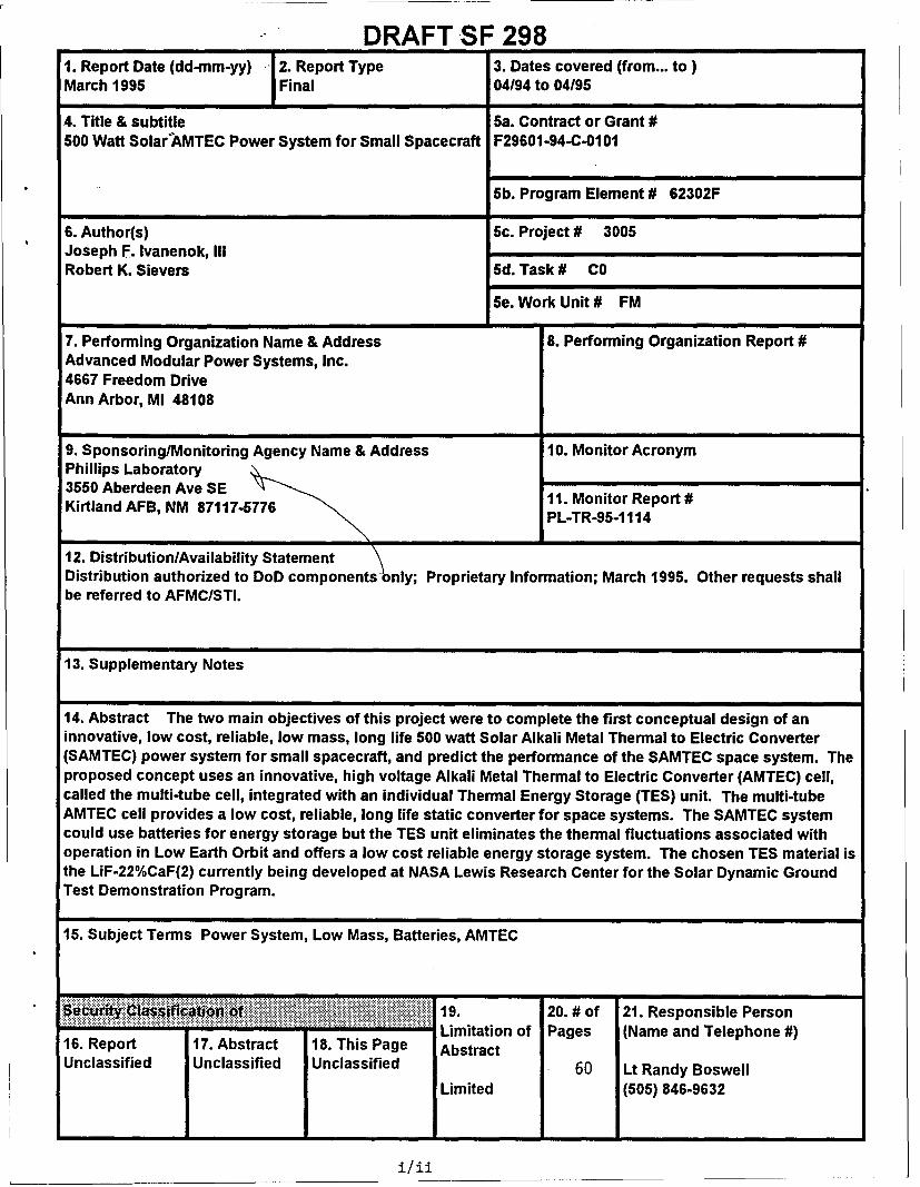
DRAFT SF 2981. Report Date (dd-mm-yy) 2. Report Type 3. Dates covered (from... to)March 1995 Final 04/94 to 04/95
4. Title & subtitle 5a. Contract or Grant #500 Wait Solar-AMTEC Power System for Small Spacecraft F29601-94-C-0101
5b. Program Element # 62302F
6. Author(s) 5c. Project# 3005Joseph F. Ivanenok, IIIRobert K. Sievers 6d. Task # CO
5e. Work Unit # FM
7. Performing Organization Name & Address 8. Performing Organization Report #Advanced Modular Power Systems, Inc.4667 Freedom DriveAnn Arbor, MI 48108
9. Sponsoring/Monitoring Agency Name & Address 10. Monitor AcronymPhillips Laboratory3550 Aberdeen Ave SE 11. Monitor Report #Kirtland AFB, NM 87117-5776 PL-TR-95-1 114
12. Distribution/Availability StatementDistribution authorized to DoD components nly; Proprietary Information; March 1995. Other requests shallbe referred to AFMC/STI.
13. Supplementary Notes
14. Abstract The two main objectives of this project were to complete the first conceptual design of aninnovative, low cost, reliable, low mass, long life 500 waft Solar Alkali Metal Thermal to Electric Converter(SAMTEC) power system for small spacecraft, and predict the performance of the SAMTEC space system. Theproposed concept uses an innovative, high voltage Alkali Metal Thermal to Electric Converter (AMTEC) cell,called the multi-tube cell, integrated with an individual Thermal Energy Storage (TES) unit. The multi-tubeAMTEC cell provides a low cost, reliable, long life static converter for space systems. The SAMTEC systemcould use batteries for energy storage but the TES unit eliminates the thermal fluctuations associated withoperation in Low Earth Orbit and offers a low cost reliable energy storage system. The chosen TES material isthe LiF-22%CaF(2) currently being developed at NASA Lewis Research Center for the Solar Dynamic GroundTest Demonstration Program.
15. Subject Terms Power System, Low Mass, Batteries, AMTEC
ssitio i i of 19. 20. # of 21. Responsible PersonLimitation of Pages (Name and Telephone #)16. Report 17. Abstract 18. This Page Abstract
Unclassified Unclassified Unclassified 60 Lt Randy Boswell
Limited (505) 846-9632
I i/i
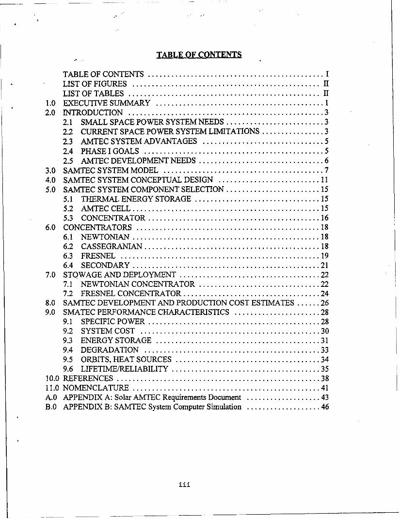
TABLE OF CONTENTS
TABLE OF CONTENTS ............................................. ILIST OF FIGURES ................................................ IILIST OF TABLES ................................................. II
1.0 EXECUTIVE SUMMARY ........................................... 12.0 INTRODUCTION .................................................. 3
2.1 SMALL SPACE POWER SYSTEM NEEDS ......................... 32.2 CURRENT SPACE POWER SYSTEM LIMITATIONS ................ 32.3 AMTEC SYSTEM ADVANTAGES ............................... 52.4 PHASE I GOALS .............................................. 52.5 AMTEC DEVELOPMENT NEEDS ................................ 6
3.0 SAMTEC SYSTEM MODEL ......................................... 74.0 SAMTEC SYSTEM CONCEPTUAL DESIGN .......................... 115.0 SAMTEC SYSTEM COMPONENT SELECTION ........................ 15
5.1 THERMAL ENERGY STORAGE ................................ 155.2 AM TEC CELL ................................................ 155.3 CONCENTRATOR ............................................ 16
6.0 CONCENTRATORS ............................................... 186.1 NEW TONIAN ................................................ 186.2 CASSEGRANIAN ............................................. 186.3 FRESNEL ................................................... 196.4 SECONDARY ................................................ 21
7.0 STOWAGE AND DEPLOYMENT .................................... 227.1 NEWTONIAN CONCENTRATOR ............................... 227.2 FRESNEL CONCENTRATOR ................................... 24
8.0 SAMTEC DEVELOPMENT AND PRODUCTION COST ESTIMATES ...... 269.0 SMATEC PERFORMANCE CHARACTERISTICS ...................... 28
9.1 SPECIFIC POW ER ............................................ 289.2 SYSTEM COST .............................................. 309.3 ENERGY STORAGE .......................................... 319.4 DEGRADATION ............................................. 339.5 ORBITS, HEAT SOURCES ..................................... 349.6 LIFETIME/RELIABILITY ....................................... 35
10.0 REFERENCES .................................................... 3811.0 NOMENCLATURE ................................................ 41A.0 APPENDIX A: Solar AMTEC Requirements Document ................... 43B.0 APPENDIX B: SAMTEC System Computer Simulation ................... 46
iii
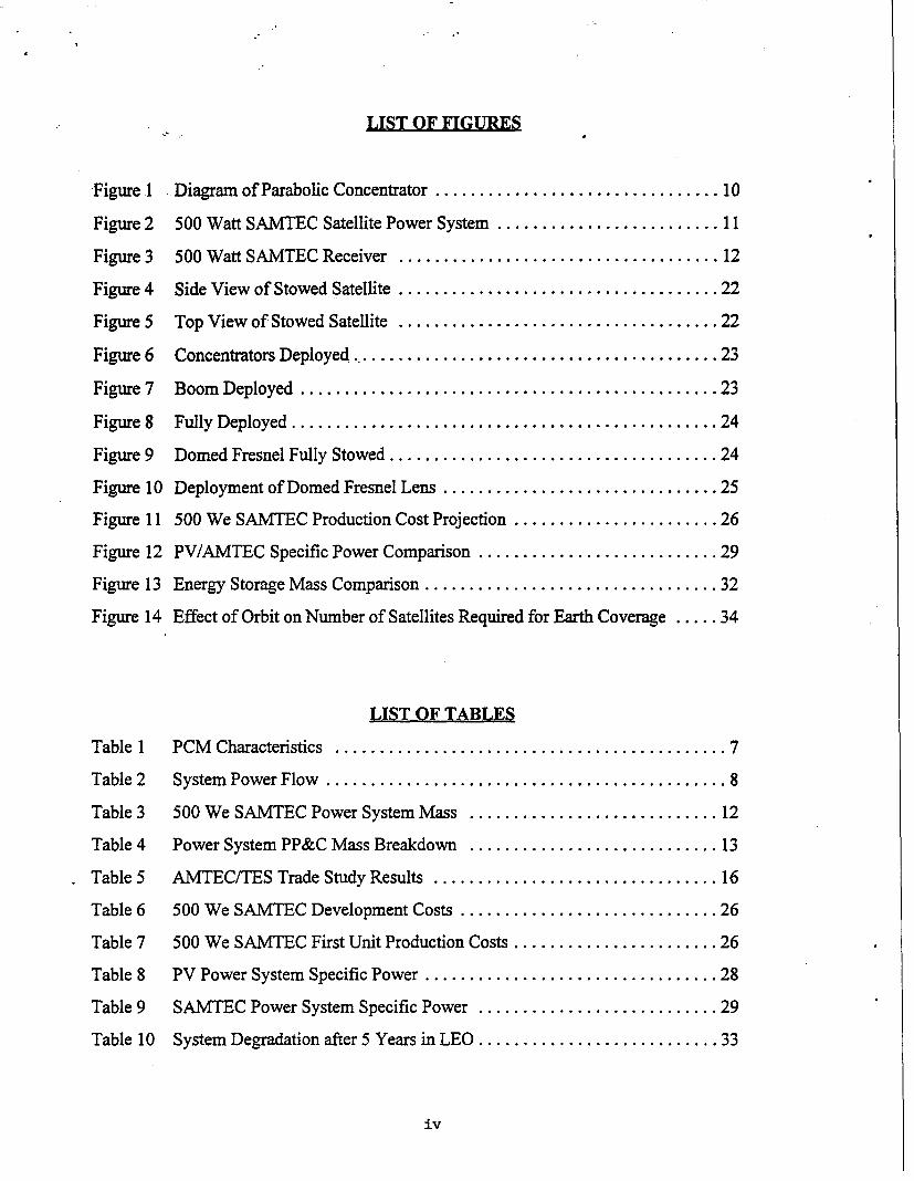
LIST OF FIGURES
Figure 1 Diagram of Parabolic Concentrator ................................ 10
Figure 2 500 Watt SAMTEC Satellite Power System ......................... 11
Figure 3 500 Watt SAMTEC Receiver .................................... 12
Figure 4 Side View of Stowed Satellite .................................... 22
Figure 5 Top View of Stowed Satellite .................................... 22
Figure 6 Concentrators Deployed ..................... 23
Figure 7 Boom Deployed ............................................... 23
Figure 8 Fully Deployed ................................................ 24
Figure 9 Domed Fresnel Fully Stowed ..................................... 24
Figure 10 Deployment of Domed Fresnel Lens ............................... 25
Figure 11 500 We SAMTEC Production Cost Projection ....................... 26
Figure 12 PV/AMTEC Specific Power Comparison ........................... 29
Figure 13 Energy Storage Mass Comparison ................................. 32
Figure 14 Effect of Orbit on Number of Satellites Required for Earth Coverage ..... 34
LIST OF TABLES
Table 1 PCM Characteristics ............................................ 7
Table 2 System Power Flow ............................................. 8
Table 3 500 We SAMTEC Power System Mass ............................ 12
Table 4 Power System PP&C Mass Breakdown ............................ 13
Table 5 AMTEC/TES Trade Study Results ................................ 16
Table 6 500 We SAMTEC Development Costs ............................. 26
Table 7 500 We SAMTEC First Unit Production Costs ....................... 26
Table 8 PV Power System Specific Power ................................. 28
Table 9 SAMTEC Power System Specific Power ........................... 29
Table 10 System Degradation after 5 Years in LEO ........................... 33
iv
1.0 EXECUTIVE SUMMARY
The two main objectives of this project were to complete the first conceptual design of an innovative,
low cost, reliable, low mass, long life 500 watt Solar Alkali Metal Thermal to Electric Converter
(SAMTEC) power system for small spacecraft, and predict the performance of the SAMTEC space
system. The proposed concept uses an innovative, high voltage Alkali Metal Thermal to Electric
Converter (AMTEC) cell, called the multi-tube cell, integrated with an individual Thermal Energy
Storage (TES) unit. The multi-tube AMTEC cell provides a low cost, reliable, long life static
converter for space systems. The SAMTEC system could use batteries for energy storage but the
TES unit eliminates the thermal fluctuations associated with operation in Low Earth Orbit (LEO)
and offers a low cost reliable energy storage system. The chosen TES material is the LiF-22%CaF2
currently being developed at NASA Lewis Research Center (LeRC) for the Solar Dynamic Ground
Test Demonstration (SDGTD) Program.
The conceptual design is based on a set of Phillips Laboratory-furnished design requirements. The
system was required to provide 500 watts electrical power at 28 volts to the payload in Low Earth
Orbit (800 kin, 28.5' inclination) for 5 years. Based on the optical and thermal analyses, the Phase
I effort showed that the conceptual design met or exceeded all of the design requirements that could
be addressed during Phase I.
The SAMTEC power system is predicted to have a specific power of 5.3 to 8.9 We/kg (including
the concentrator, receiver, AMTEC cells, gimbals and drives, structure, power processing and
control, and a 30% mass contingency) at the 500 watt power level, and 12 to 17 We/kg (including
all of the components listed above) at the 5,000 watt power level. The SAMTEC system, including
all of the components listed above, is anticipated to cost $1,000/We once development is complete
and production begins. The SAMTEC system provides 92% of its Beginning of Life (BOL) power
after a 5 year period in LEO, and SAMTEC systems should provide 10 to 15 years of life in LEO.
Current AMTEC cells have demonstrated 18% efficiency in the laboratory and have been heated
radiatively, with propane flames and electrical resistance heaters.
I
The SAITEC system has certain unique performance characteristics. AMTEC cells can be operated
using any heat source (solar, combustion, nuclear, etc.). Radioisotope power system designs have
been completed (currently AMTEC is the conversion technology of choice for the Pluto Express
mission at the Jet Propulsion Laboratory), and the several combustion heated AMTEC systems are
currently in conceptual design stages (including auxiliary electric power supplies and hybrid electric
vehicles). A SAMTEC power system can be made to operate in high radiation environments, like
that encountered in the Van Allen belts. These unique capabilities will lead to a wide range of
applications, and take advantage of greater economies of scale. This will lower the cost of space
systems.
The Phase I produced a significant milestone for AMTEC technology - the first detailed system
design and performance prediction of a solar powered AMTEC space power system. There are
several key steps that need to be completed to successfully develop AMTEC cells and systems for
space and terrestrial applications. The first is to fully develop the multi-tube AMTEC cells and
integrate them with the TES units. The first multi-tube AMTEC cell was successfully tested in
February of 1995, the first AMITEC/TES cell will be tested in summer of 1995, and multi-tube cell
development will continue in Phase 2 of this Small Business Innovative Research (SBIR) program.
The second is to complete a detailed system design, and spacecraft integration of the SAMTEC
space power system, which will also be completed during Phase 2. The third step is a flight test of
the AMTEC cells, which has been proposed (and is currently under review) to NASA under the In
Space Technology Experiment Program (InSTEP). The final step is to fabricate and test a system
prototype in the relevant environment, high vacuum, which will also be completed at the end of
Phase 2. Once these steps have been completed, SAMTEC will have the necessary background to
begin convincing satellite users to adopt AMTEC technology.
2
2.0 INTRODUCTION
2.1 SMALL SPACE POWER SYSTEM NEEDS
There is a strong drive to reduce the cost of both government and commercial space operations. This
reduction in system cost must not be made at the expense of mission performance, lifetime, and
reliability. Since the electrical power system and related components in today's state-of-the-art,
small spacecraft account for 30%-60% of the total spacecraft mass and 10%-20% of the cost, a
smaller, less expensive power system would help satisfy this need. The challenge of Phase I was
to provide the desired performance increase at a lower cost and acceptable technical risk, while
maintaining or improving system lifetime, durability, and reliability. The results of the Phase I effort
show that this is feasible, if AMTEC cells are combined with TES units.
2.2 CURRENT SPACE POWER SYSTEM LIMITATIONS
For spacecraft operating on solar input in earth orbit, normal operation requires a power supply that
can function throughout the orbit, in spite of the frequent eclipse periods experienced due to passage
through the earth's solar shadow. Provision of the energy storage to maintain operation during
eclipse periods is a critical element in power systems for such applications.
Current approaches to providing electrical power for spacecraft in earth orbit rely primarily on
PhotoVoltaic (PV) cells with batteries for eclipse periods. Current PV power systems have a specific
power of approximately 4-5 We/kg, at the 500 We power level, and cost approximately $5,000-
$10,000/We for the entire power system (system includes PMAD, batteries, PV arrays, etc.). The
large mass, and resulting low specific power, can be attributed to both the mass of the required
energy storage and the need to oversize the system, to compensate for the degradation of PV output
with time.
Current space solar power systems rely heavily on batteries for storing the energy required during
3
eclipse periods. With current and projected near term battery technology, a high number of cycles
is required in long term, low to middle earth orbits. Therefore, the batteries satellites must use for
-energy storage have a shallow depth of discharge. This results in a massive energy storage system;
approximately 20 kg for a 500 We power system (NiH2, 50 W hr.Ikg, 30 % Depth of Discharge).
The time dependent degradation mechanisms for PV systems can be classified into four main types:
1) charged particle degradation of the active cell; 2) Ultra-Violet (UV) darkening of the adhesive
used to hold the cover glass; 3) natural and man-made debris damage and 4) power losses through
random failure of cells, connections, circuits, etc. According to Kimber and Goodbody (1994) PV
arrays typically retain 75%-85% of their BOL power after 5 years in LEO. The array degradation
due to charged particle/radiation levels in the "middle" Van Allen belt orbits is so severe that it
makes long term PV operation difficult. Japan's ETS-6 satellite is an example of how radiation can
severely degrade the performance of PV arrays. The ETS-6 satellite produced 5.8 kWe on
September 3, 1994 and 10 days later produced only 5.3 kWe. The satellite was accidentally placed
in an elliptical orbit (4,800 x 24,000 mile, through the Van Allen belts) when its apogee kick motor
failed to achieve proper pressure. The power is predicted to be below 2 kWe in approximately 12
months making the satellite unusable (Ref. 2).
Because the PV's proposed for space systems can use only direct solar energy, they do not easily
lend themselves to numerous large scale terrestrial applications. Many terrestrial PV systems must
use a fuel fired system, or batteries, as a backup to the PV's to produce electricity in the absence of
solar insolation. The reduced ability of PV systems to be utilized in some of the high volume
terrestrial markets reduces cell production volume and reduces the cost advantages attributed to high
volume production. This, indirectly, sustains the high cost of space power systems. The results of
the Phase I effort show that the AMTEC conceptual design has the potential for eliminating all of
the current space power limitations, and has numerous commercial space and terrestrial applications.
Commercial interest in AMTEC has been demonstrated by industrial corporations such as, Arthur
D. Little, Teledyne Brown, Global Thermoelectric, and Rocketdyne.
4
2.3 AMTEC SYSTEM ADVANTAGES
The results of the Phase I effort show that combining an innovative AMTEC generator concept with
a fully integrated TES system produces a small, high performance, and inexpensive power system
that maintains or improves lifetime, durability, and reliability of the satellite.. The conceptual design
of the 500 We SAMTEC system was completed during the Phase I effort. The results indicate that
the SAMTEC power system is predicted to have a specific power of 5.3 to 8.9 We/kg (including the
concentrator, receiver, AMTEC cells, gimbals and drives, structure, power processing and control,
and a 30% mass contingency) at the 500 watt power level, and 12 to 17 We/kg (including all of the
components listed above) at the 5,000 watt power level. The SAMTEC system, including all of the
components listed above, is predicted to cost $1,000/We once development is complete and
production begins. The SAMTEC system provides 92% of its Beginning of Life (BOL) power after
a 5 year period in LEO, and SAMTEC systems should provide 10 to 15 years of life in LEO. The
SAMTEC system's resistance to radiation also allows operation in Middle Earth Orbits (MEO)
where it encounters the Van Allen radiation belts. Operation in such orbits can significantly reduce
the number of satellites required for global coverage, thus reducing the overall cost of a global
communications satellite constellation. The AMTEC cells designed and used for the solar system
can also be used in systems heated with a reactor, radioisotope, or combustor for other space or
terrestrial applications. This capability will lead to a large markets for AMTEC cells and thus to
large economies of scale in production.
2.4 PHASE I GOALS
The two main goals of the Phase I program were to complete the conceptual design of an innovative,
low cost, reliable, low mass, long life 500 watt solar power system for small spacecraft, and predict
the performance of the SAMTEC space power system. Sections 4.0 describes the conceptual design
of the 500 We SAMTEC system, and section 5.0 describes the components selected for the system
design. Section 8.0 shows the predicted performance of the SAMTEC system, and compares it to
the performance of current PV systems. The Phase I program provided the proof-of-principle
5
necessary.for a SAMTEC system by producing the first detailed system design and performance
predictions. The results of the Phase I effort demonstrate SAMTEC's ability to provide high system
performance at a low system cost while maintaining or improving system lifetime, durability, and
reliability.
2.5 AMTEC DEVELOPMENT NEEDS
There are several key steps that need to be completed to successfully develop AMTEC cells and
systems for space and terrestrial applications. The multi-tube AMTEC cell needs to be developed
to a level consistent with the single tube AMTEC cell now being produced at Advanced Modular
Power Systems, Inc. (AMPS), and it needs to be integrated with the TES. The first is to fully
develop the multi-tube AMTEC cells and integrate them with the TES units. The first multi-tube
AMTEC cell was successfully tested in February of 1995, the first AMTEC/TES cell will be tested
in summer of 1995, and multi-tube cell development will continue in Phase 2 of this Small Business
Innovative Research (SBIR) program. System design and performance models should be refined in
order to determine, with a very high confidence level, the performance of the proposed AMTEC
technology in comparison with the established space power systems. A detailed system design, and
spacecraft integration of the SAMTEC space power system is also necessary, and will be completed
during Phase 2. The cell and system development can then converge to produce a working system
prototype in the relevant environment, high vacuum, which will also be completed at the end of
Phase 2. The final step is a flight test of the AMTEC cells, which has been proposed (and is
currently under review) to NASA under the In Space Technology Experiment Program (InSTEP).
Once these steps have been completed, SAMTEC will have the necessary background to begin
convincing satellite users to adopt AMTEC technology.
6
3.0 SAMTEC SYSTEM MODEL
The SAMTEC system model was developed to predict conservative estimates of the mass and
performance for several receiver, AMTEC cell, TES, and concentrator design options. Receiver
design options include single and multi-tube AMTEC cells, LiF and LiF-22%CaF2 Phase Change
Material (PCM) for TES, and overall receiver configuration/geometry. The system model does not
calculate individual cell performance. The cell performance is calculated with independent AMTEC
cell models developed at Advanced Modular Power Systems, Inc. (AMPS) and then used as input
to the system model. This allows several different AMTEC cell designs to be evaluated in the
system without changing the entire system model. The system model requires the following
information about the AMTEC cells used in the system: Outside Diameter, Length, Mass, Power,
Efficiency.
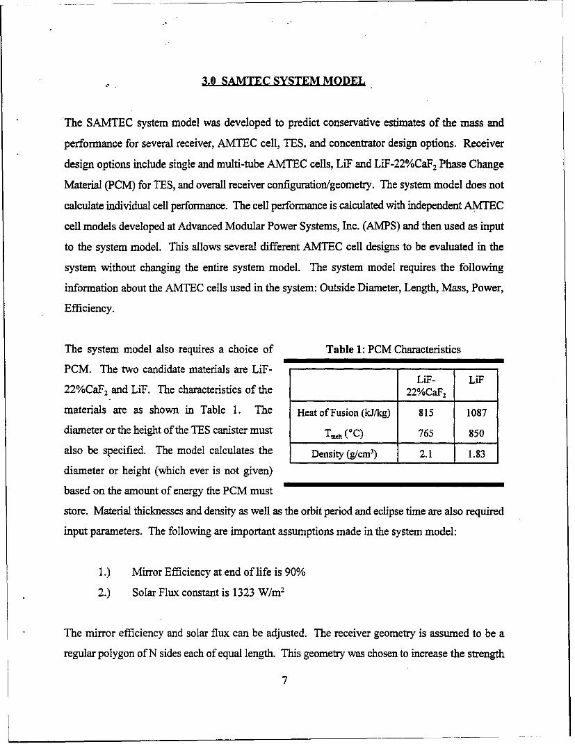
The system model also requires a choice of Table 1: PCM Characteristics
PCM. The two candidate materials are LiF-LiF- LiF
22%CaF2 and LiF. The characteristics of the 22%CaF 2
materials are as shown in Table 1. The Heat of Fusion (kJ/kg) 815 1087
diameter or the height of the TES canister must Tmc11 (0C) 765 850
also be specified. The model calculates the Density (g/cm3) 2.1 1.83
diameter or height (which ever is not given)
based on the amount of energy the PCM must
store. Material thicknesses and density as well as the orbit period and eclipse time are also required
input parameters. The following are important assumptions made in the system model:
1.) Mirror Efficiency at end of life is 90%
2.) Solar Flux constant is 1323 W/m2
The mirror efficiency and solar flux can be adjusted. The receiver geometry is assumed to be a
regular polygon of N sides each of equal length. This geometry was chosen to increase the strength
7
of the receiver and simplify the integration of the cells with the receiver walls. The number of sides
of the receiver is chosen so that each side can be connected in series to form a single string the
required voltage. For example, if the cells are 3.5 volts and the requirement is 28 volts the receiver
would have 8 sides. The number of cells per side is then increased to provide the desired output
power. This allows a number of different cell voltages to be analyzed.
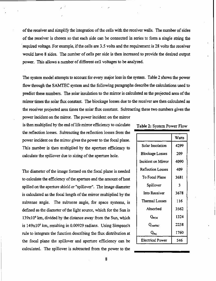
The system model attempts to account for every major loss in the system. Table 2 shows the power
flow through the SAMTEC system and the following paragraphs describe the calculations used to
predict these numbers. The solar insulation to the mirror is calculated as the projected area of the
mirror times the solar flux constant. The blockage losses due to the receiver are then calculated as
the receiver projected area times the solar flux constant. Subtracting these two numbers gives the
power incident on the mirror. The power incident on the mirror
is then multiplied by the end of life mirror efficiency to calculate Table 2: System Power Flow
the reflection losses. Subtracting the reflection losses from the
power incident on the mirror gives the power to the focal plane. WattsSolar Insolation 4299
This number is then multiplied by the aperture efficiency to
calculate the spillover due to sizing of the aperture hole. Blockage Losses 209Incident on Mirror 4090
The diameter of the image formed on the focal plane is needed Reflection Losses 409
to calculate the efficiency of the aperture and the amount of heat To Focal Plane 3681
spilled on the aperture shield or "spillover". The image diameter Spillover 3
is calculated as the focal length of the mirror multiplied by the Into Receiver 3678
subtense angle. The subtense angle, for space systems, is Thermal Losses 116
defined as the diameter of the light source, which for the Sun is Absorbed 3562
139x10 4 kin, divided by the distance away from the Sun, which QKM 1324
is 149xl06 km, resulting in 0.00929 radians. Using Simpson's QAMC 2238
rule to integrate the function describing the flux distribution at QRj. 1760
the focal plane the spillover and aperture efficiency can be Electrical Power 546
calculated. The spillover is subtracted from the power to the
8
focal plane giving the power into the receiver. The heat loss through the multi-layer heat shields is
then calculated. Determan et al (1989) gives the following equation, determined experimentally, for
the heat loss through Multi-Layer Insulation (MLI):
Al. 06E-8 (T 4 -T 4 )Q 1 2
(0.788N+1. 11E-2 N 2 )
where A is the area normal to the heat flux, T, and T2 are the boundary temperatures, and N is the
number of layers of heat shields. The loss out the aperture hole is calculated as blackbody radiation
to space. These two losses combine to give the total thermal losses out the receiver. Subtracting
these losses from te power into the receiver yields the power absorbed by the PCM and AMTEC
subsystems. The heat that the PCM requires to keep the system running during the eclipse period
is calculated as follows:
te (P.O. +Q ej +Qoh )
ti
where te is the eclipse time, ti is the insolation time, Pt,, is the system power output, Qoh is the heat
radiated out the aperture hole, and Q,,j is the heat rejected from the system to space and is calculated
as follows:
Ptot
Qrej =E tPtot + Qthssys
where ESYS is the AMTEC cell efficiency, g, is the system output power, andQ is the losses
through the heat shields as described earlier. The final power flow calculation is the power required
by the AMTEC cells which is the cell output power over the cell efficiency. The system model also
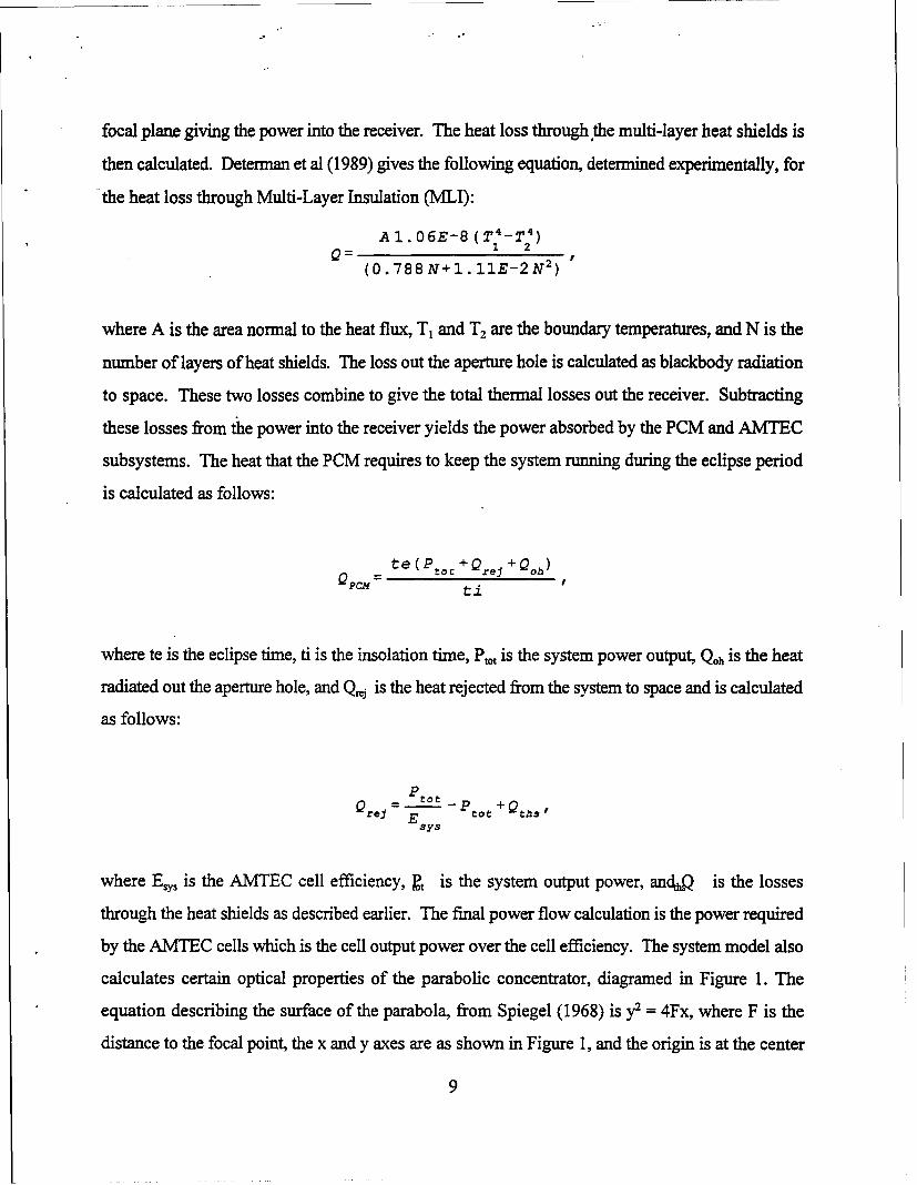
calculates certain optical properties of the parabolic concentrator, diagramed in Figure 1. The
equation describing the surface of the parabola, from Spiegel (1968) is y2 = 4Fx, where F is the
distance to the focal point, the x and y axes are as shown in Figure 1, and the origin is at the center
9
of the parabola. The rim angle, shown
in Figure 1, is defined as the angle
between an incoming light ray, at the Y-01,1 Tangent LinenoigL ightl Ray
rim, which is parallel to the focal plane Rim Angle
(AplhoI
and a line tangent to the parabola at the 1,0-2.Alph
rim. The slope of the tangent line is
equal to the tangent of the rim angle andX-ax is
also equal to the derivative, at the rim,
of the equation describing the parabolic
surface. Taking the required derivative
and substituting the tangent of the rim
angle for dy/dx gives the following
equation for calculating the focal length: Figure 1 Diagram of Parabolic Concentrator
F = Y/2*TAN(alpha), where alpha is the
rim angle, and Y is the radius of the concentrator determined by the area required to intercept the
desired solar flux. Once the focal length and radius of the concentrator have been determined they
can be used, by substituting into the equation describing a parabola, to calculate the depth, or x
coordinate corresponding to the radius, of the concentrator. These equations produce reasonable
calculations of the optical properties of a parabolic concentrator which help in sizing the system and
its integration with the satellite.
The final unknown in this system of equations is the radiator area or temperature. If the radiator area
is assumed to be the surface area of the receiver then these equations can be iteratively solved based
on the radiator temperature. If the area is assumed to be a variable then the desired radiator
temperature is specified and the equations iteratively solve around the radiator area. A sample copy
of the model inputs, outputs, and equations is included at the end of this report in Appendix B. The
model described here was used to complete the trade studies and component selection described in
section 4.0 and 5.0 of this report.
10
4.0 SAMTEC SYSTEM CONCEPTUAL DESIGN
The two main goals of the Phase I program were to complete the conceptual design of an innovative,
low cost, reliable, low mass, long life 500 watt solar power system for small spacecraft, and predict
the performance of the SAMTEC space power system. The conceptual design is based on a set of
Phillips Laboratory-furnished design requirements which can be found in Appendix A. The system
was designed to provide 500 watts electrical power at 28 volts to the payload in Low Earth Orbit
(800 1am, 28.5* inclination) for 5 years. Based on the optical and thermal analyses, a conceptual
design of a 500 watt solar AMTEC space
power system has been recommended.
The Phase I effort showed that the CONCENTRTORS
conceptual design met or exceeded all of
the design requirements that could be
addressed during the project. Section 5 /
describes the trade studies used to select
the system components, and Section 4
describes the conceptual design of the
500 We SAMTEC system. Section 8
shows the predicted performance of the RECEERS
SAMTEC system and compares it to
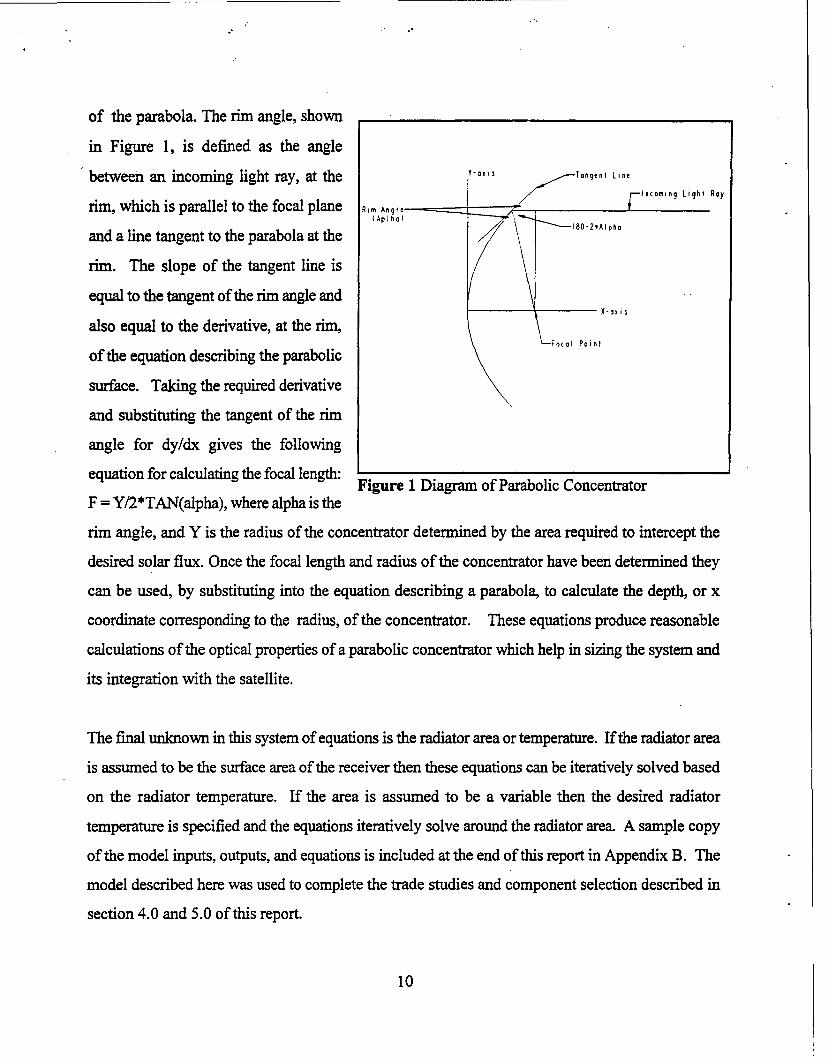
current PV arrays. Figure 2: 500 Watt SAMTEC Satellite Power System
Figure 2 shows the conceptual design of a 500 watt SAMTEC, integrated with the GPS Block IR
spacecraft. The GPS Block IIR was used only as a concrete example of a spacecraft bus. This power
system was designed during Phase I to provide a low cost, reliable, low mass, long life power system
for small spacecraft. The SAMTEC system consists of the following four main sub-systems:
1.) Concentrator (Fresnel, Newtonian, or Cassegranian, Fresnel shown)
2.) Multi-Tube AMTEC cells
11
3.) LiF-22%CaF 2 Thermal Energy Storage (TES)
4.) State-of-the-art Power Management and Distribution (PMAD)
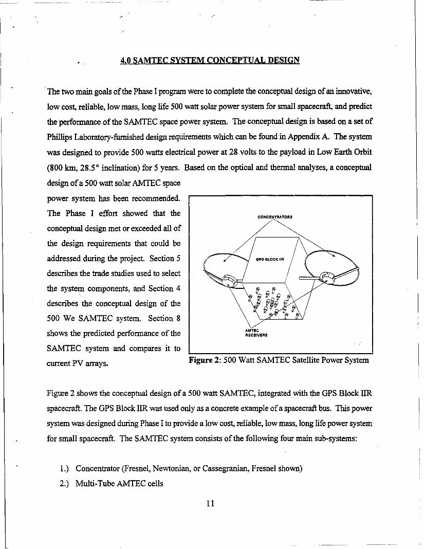
The receiver, shown in Figure 3, is comprised of the required number of AMTEC/TES units to
produce the desired voltage and power. Each AMTEC/TES unit contains a single LiF-22%CaF2 TES
unit and a single multi-tube AMTEC cell.
A regular octagon configuration was used
Housing
Table 3: 500 We SAMTEC Power ThermalEnergySystem Mass Mounting Stud Storage (TES)
and Nut\ '
Electrical Power (W) 500
Specific Power (W/kg) 8.2 CellsCell Eff. (%) 24.4
Net System Eff. (%) 19.8
Component Mass (kg) Cell Holder
Electrical Insulation 0.39 Note: Multi-Layer Insulation Not Shown
Receiver 1.43
TES 9.32MLI 0.98
AMTEC Cells 3.31 Figure 3: 500 Watt SAMTEC ReceiverConcentrator 2.76
Aperture Shield 0.82
Gimbals and Drives 3.00 to increase the strength of the receiver and simplify the
Structure 3.00 integration of the cells with the receiver. The number ofPP&C 22.00
Mass Contingency 14.10 sides of the receiver is chosen so that each side can beIotal 61.11 connected in series to form a single string the required
voltage. In this design, each cell provides 3.5 volts at the
normal operating point, and the 28 volt requirement is
met with a receiver having a cell mounted on each of its 8 faces. The number of cells mounted to
each face is then increased to provide the desired output power. In this design, each cell provides
23 watts of electricity and each string can deliver 184 watts. Since the system requirement is 500
watts (500 watts to the payload and 52 to the PMAD system), three strings (3 cells per side) provide
the required power. The cells are connected in a series/parallel ladder arrangement to provide the
12
highest level of system reliability. Table 3 shows the estimated mass of the components in the 500
We SAMTEC pictured in Figure 2. The receiver housing is made from carbon-carbon composite
material to lower the mass of the system. The TES canisters are made form Haynes 188 alloy (the
material used for the SDGTD Program TES units), the multi-layer heat shields use molybdenum foil,
and the cell walls are Inconel. Mass could be saved by selecting different materials for these
components, but they account for only 15% of the system mass, and any mass savings would only
have a minimal effect on the overall system mass.
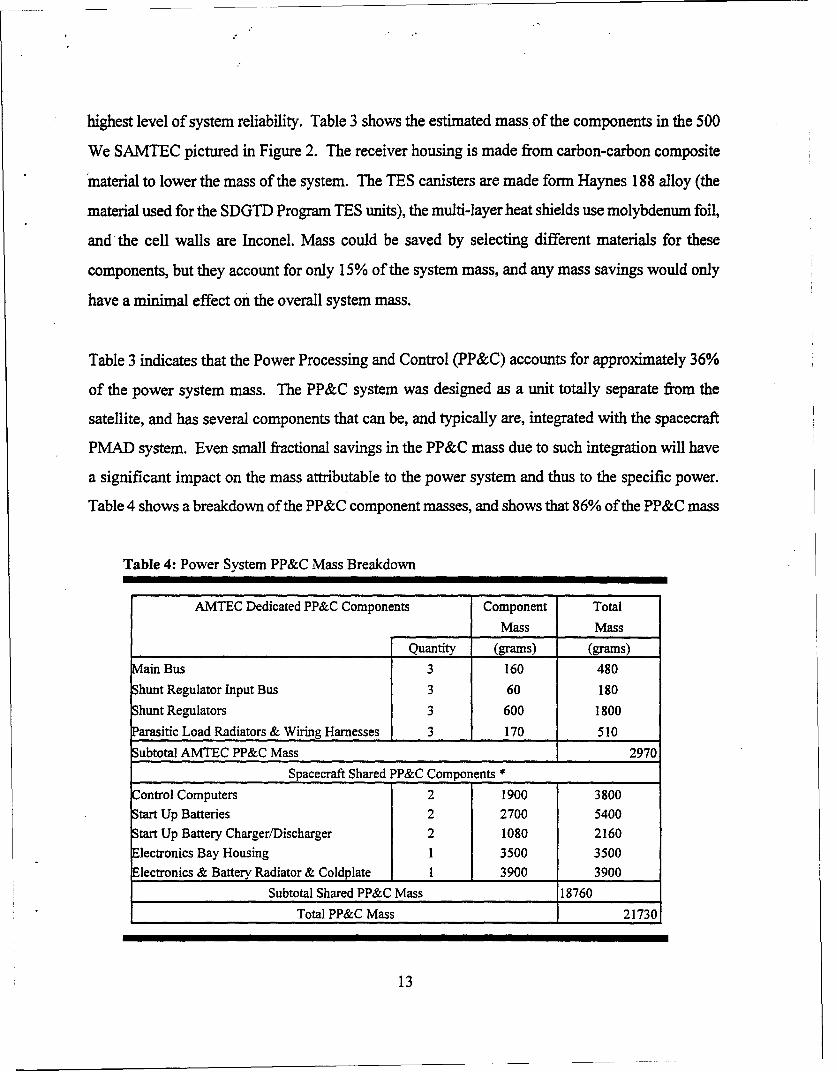
Table 3 indicates that the Power Processing and Control (PP&C) accounts for approximately 36%
of the power system mass. The PP&C system was designed as a unit totally separate from the
satellite, and has several components that can be, and typically are, integrated with the spacecraft
PMAD system. Even small fractional savings in the PP&C mass due to such integration will have
a significant impact on the mass attributable to the power system and thus to the specific power.
Table 4 shows a breakdown of the PP&C component masses, and shows that 86% of the PP&C mass
Table 4: Power System PP&C Mass Breakdown
AMTEC Dedicated PP&C Components Component TotalMass Mass
Quantity (grams) (grams)
ain Bus 3 160 480hunt Regulator Input Bus 3 60 180hunt Regulators 3 600 1800arasitic Load Radiators & Wiring Harnesses 3 170 510
Subtotal AMTEC PP&C Mass 2970Spacecraft Shared PP&C Components *
Control Computers 2 1900 3800Start Up Batteries 2 2700 5400Start Up Battery Charger/Discharger 2 1080 2160Electronics Bay Housing 1 3500 3500Electronics & Battery Radiator & Coldplate 1 3900 3900
Subtotal Shared PP&C Mass 18760
Total PP&C Mass 21730
13
is due to components that can be combined/shared with the existing spacecraft PMAD system. This
indicates that the system component with the largest mass is comprised mostly of components that
can be combined with the spacecraft, thus lowering the power system mass and increasing the
specific power. However, even without credit for any component sharing, the system pictured in
Figure 2 is predicted to have a specific power of 8.2 We/kg and a system efficiency of 19.8% based
on the intercepted solar radiation.
14
5.0 SAMTEC SYSTEM COMPONENT SELECTION
The following is a list of the recommended components for the 500 We SAMTEC power system and
a brief justification for the selection.
5.1 THERMAL ENERGY STORAGE
LiF-22%CaF 2 PCM - This material is chosen based on the results of the development funded under
the SDGTD Program at the NASA Lewis Research Center. The system trade study, results in Table
5, show that LiF provides only a modest increase in performance (specific power increases of only
0.7-1.0 We/kg) compared to the LiF-22%CaF2, with a substantial increase in receiver temperature
(765°C to 850°C). The higher temperature operation using LiF could require the use of refractory
materials, which could effect lifetime and would increase the cost for developing and producing the
system. Therefore, LiF-22%CaF2 is the PCM chosen for this system. The cell efficiency is higher
for the LiF PCM because the operating temperature is higher. The models used for this analysis
indicate that the gain in efficiency is small, but more detailed cell models, which are to be used
during Phase 2, may show a greater difference between the two operating temperatures.
5.2 AMTEC CELL
Multi-Tube AMTEC Cells - The system trade showed that the multi-tube AMTEC cells provide
a significant increase in system performance (efficiency increased from 17.6% to 24.4% and the
mass decreased by 34 kg for a specific power increase of 3 We/kg) compared to single tube AMTEC
cells. The increase in risk for selecting the multi-tube cell is minor (single-tube cells are NASA
Level 4 and multi-tube are NASA Level 3). However, all of the development that has gone into
single-tube cells is directly applicable to multi-tube cells. Table 5 shows the performance and mass
of several AMTEC cell/TES systems, predicted using the analytical system models developed during
Phase I and described in Section 3.0 of this report. The multi-tube AMTEC cell was chosen based
on its substantial increase in performance, compared to the single-tube, and only minor increase in
risk. However, it should be noted that even the off-the-shelf-system comprised of single-tube
15
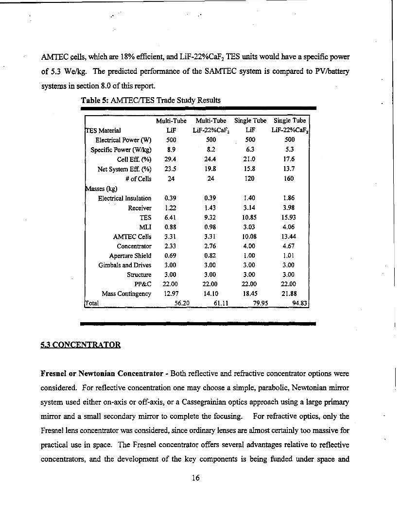
AMTEC cells, which are 18% efficient, and LiF-22%CaF2 TES units would have a specific power
of 5.3 We/kg. The predicted performance of the SAMTEC system is compared to PV/battery
systems in section 8.0 of this report.
Table 5: AMTEC/TES Trade Study Results
Multi-Tube Multi-Tube Single Tube Single Tube
TES Material LiF LiF-22%CaF2 LiF LiF-22%CaF2
Electrical Power (W) 500 500 500 500
Specific Power (W/kg) 8.9 8.2 6.3 5.3
Cell Eff. (%) 29.4 24.4 21.0 17.6
Net System Eff. (%) 23.5 19.8 15.8 13.7# of Cells 24 24 120 160
Masses (kg)Electrical Insulation 0.39 0.39 1.40 1.86
Receiver 1.22 1.43 3.14 3.98TES 6.41 9.32 10.85 15.93
MLI 0.88 0.98 3.03 4.06AMTEC Cells 3.31 3.31 10.08 13.44
Concentrator 2.33 2.76 4.00 4.67Aperture Shield 0.69 0.82 1.00 1.01
Gimbals and Drives 3.00 3.00 3.00 3.00Structure 3.00 3.00 3.00 3.00
PP&C 22.00 22.00 22.00 22.00
Mass Contingency 12.97 14.10 18.45 21.88fotal 56.20 61.11 79.95 94.83
5.3 CONCENTRATOR
Fresnel or Newtonian Concentrator - Both reflective and refractive concentrator options were
considered. For reflective concentration one may choose a simple, parabolic, Newtonian mirror
system used either on-axis or off-axis, or a Cassegrainian optics approach using a large primary
mirror and a small secondary mirror to complete the focusing. For refractive optics, only the
Fresnel lens concentrator was considered, since ordinary lenses are almost certainly too massive for
practical use in space. The Fresnel concentrator offers several advantages relative to reflective
concentrators, and the development of the key components is being funded under space and
16
terrestrial concentrated PV programs. A description of the advantages a Fresnel concentrator offers,
relative to various reflective concentrator options, is included below. The Phase I effort could not
provide the detail necessary to select the best concentrator. Based on the information gathered in
the Phase I effort the Fresnel has definite advantages over reflective concentrators and if the
materials issue has been solved should be the concentrator of choice. However, until a detailed
spacecraft integration analysis can be completed in Phase 2 the only recommendation is that
reflective and refractive concentrators should be further analyzed.
17
6.0 CONCENTRATORS
6.1 NEWTONIAN
The simple Newtonian mirror system requires high accuracy pointing and minimum slope errors in
order to achieve the concentration ratio required to reach AMTEC operating temperatures. A portion
of the reflecting area is blocked by the receiver, which must be located in front of the mirror surface.
A degradation of the reflectivity to about 90% is to be expected over a period of 10 years in orbit.
Of the reflective concentrators, this is probably the best choice for simplicity, mass, and minimal
degradation with exposure time.
6.2 CASSEGRANIAN
A Cassegranian concentrator was also evaluated and this approach was not chosen for several
reasons. The two-mirror configuration will have higher reflection losses simply due to the second
reflection required. If a single mirror is expected to be reduced to 90% reflectivity at the end of ten
years, Cassegranian optics would be expected to suffer a reduction to 81% over the same period.
Compensation for this would require a larger system and the added beginning of life power would
then have to be dissipated (larger PMAD system and larger concentrator area further complicating
stowage and deployment). Further, the Cassegranian optics tend to form a sharp solar image on the
back wall of the receiver increasing the local flux and temperature at this point relative to either
Newtonian or Fresnel optics. For high concentration ratios, the secondary mirror suffers from
another problem. A small fraction of the concentrated solar flux, intercepted by the primary mirror
and directed toward the secondary mirror, is absorbed by the secondary mirror. Methods to keep the
secondary mirror cool, must therefore be incorporated, to prevent undesirable optical distortions
and/or shortened mirror lifetimes, from occurring. While adjusting a small secondary mirror to fine
tune the collector pointing is possible in principle, achieving this in practice poses a difficult control
problem (i.e. pointing two mirrors instead of one) and this then lowers the overall system reliability.
These difficulties are not present in either Newtonian or Fresnel optics.
18
A parabolic concentrator has several disadvantages for space power applications-which use of a
domed Fresnel lens eliminates. The receiver, and any required radiator, and the structure of an on-
axis parabolic concentrator system must be located at or near the focal point of the dish. In this
location, these elements of the system shade the concentrator aperture and reduce the solar energy
collection efficiency of the concentrator. For a system using a domed Fresnel concentrator, all of
these elements are behind the lens, and thus do not interfere with the collection or concentration of
the sunlight.
In addition to shading problems, parabolic concentrators require precise shape maintenance for
reasonable performance. In operation under varying temperature conditions, precise shape control
of reflectors has proven to be exceptionally difficult even for relatively massive terrestrial
concentrators. The large temperature variations associated with the eclipse periods encountered
when operating in a LEO, will make precise shape control very difficult for the ultra-light
concentrators needed for space solar systems. A dome shaped Fresnel lens, using a unique optical
design, eliminates the precise shape control issue. These lenses are designed such that for each
individual prism the angle of incidence of the light at the smooth outer lens surface is equal to the
angle of emergence at the inner lens surface. This symmetrical refraction condition leads to the
lowest reflection losses for each prism, and thus maximizes the transmittance through the lens, and
hence the lens efficiency. In addition to the transmittance advantage, the symmetrical refraction
prism produces a much smaller solar image than non-symmetrical refraction prisms at the same total
turning angle when effects such as; finite solar disk size, chromatic aberration, prism manufacturing
inaccuracies, and orientation are considered. Prism orientation inaccuracies correspond directly to
concentrator slope errors which makes image defocussing, due to this inaccuracy, extremely
important. Compared to reflective solar concentrators, this Fresnel lens allows 200 times the slope
error for equivalent image defocussing. The greater slope error tolerance of the Fresnel lens means
that for good optical performance, the shape is less critical. The accuracy required for concentrator
manufacturing and deployment can be relaxed, and the allowable structural deformations are larger.
19
The slopeerror tolerance relates directly to lower concentrator mass, lower manufacturing cost, and
easier manufacturing techniques.
The domed Fresnel lens also provides the capability to tailor the radiant flux profile. The Fresnel
lens consists of thousands of microscopic prisms which individually produce an image on the focal
plane. This image can be directed to almost any desired location on the focal region by selecting the
prism apex angle accordingly. Since the flux profile on the focal plane is the sum of the
contributions of all of the prisms, the lens has several thousand degrees of freedom with which to
adjust the flux profile. This flux profile tailoring has been successfully accomplished for several
different versions of terrestrial solar concentrators of similar design. The flux intensity profile over
the absorption surfaces inside the receiver cavity, can also be designed to more closely match the
heat transfer requirements, by modifying the lens prism angles. The flux profile can thus be
designed to avoid the intensely focused spots at the center of the focal plane, associated with
parabolic concentrators, which can, and do cause safety problems if the sun-tracking system
malfunctions for any reason. There are limits and trade-offs associated with tailoring the flux, but
these can only be fully evaluated with detailed design and analysis.
There is a potential materials issue associated with the light weight Fresnel lens. These lenses are
made from silicone rubber which is attacked by ultra violet rays (UV) and atomic oxygen (AO). A
coating has recently been developed that appears to eliminate this problem. The durability of the
coating is currently being tested in space. Prototypic mini-dome Fresnel lenses are on a test satellite
in an elliptic orbit reaching a maximum of 1365 nautical miles (just inside the Van Allen belts). In
this orbit they are being exposed to UV, AO, and radiation at a greater rate than had been planned
since the satellite is a higher orbit than expected. According to Mike Piszczor of NASA Lewis, and
Mark O'Neill of ENTECH the lenses have shown no degradation after five months of operation.
While this data is still preliminary and of relatively short duration, the results look promising. All
of the information on the Fresnel lens presented here originated from discussions with Mike Piszczor
at NASA Lewis and Mark O'Neill at ENTECH and from a NASA Lewis technical report prepared
by ENTECH (Ref. 5).
20
6.4 SECONDARY
One of the key issues of a SAMTEC space power system is the required pointing and tracking
accuracy. The SAMTEC system with a single reflective or refractive concentrator is predicted to
require pointing precision in the range of <±I °, which is well within current state-of-the-art
technology. However, this may impose requirement on the spacecraft that designers will not accept,
but a secondary concentrator can "loosen" this requirement to <±5* (typical of PV systems). The
following advantages of using a secondary concentrator in conjunction with a primary mirror were
identified during the Phase I effort:
1) Primary mirrors generally require pointing errors of less than 0.25 degrees, to be
captured by a minimally oversized cavity aperture opening while the use of a
secondary concentrator will relax pointing and tracking error effects. A properly
designed secondary concentrator can typically accept ±1.0 to ± 5.0 degree pointing
errors, without any loss of solar flux into the cavity.
2) Use of a secondary concentrator can typically reduce cavity opening size by a factor
of 1.5 to 3.0, reducing re-radiation thermal losses by similar factors.
3) Secondary concentrators accept diffuse sunlight, such that any sunlight ray hitting
any surface (within the designed apex acceptance angle) will be 100% absorbed
without re-reflecting out.
4) Secondary concentrators can be fabricated with highly reflective, and low emissive
surface materials to virtually eliminate surface losses.
A detailed analysis would be needed to determine if the secondary concentrator would have to be
actively cooled, its mass penalty, and determine the magnitude of the performance gain with a
chosen primary concentrator. Based on the potential benefits of the secondary concentrator it should
be considered in any future effort.
21
7.0 STOWAGE AND DEPLOYMENT
The integration of the power system with the spacecraft is a major design consideration for a
satellite. The stowage and deployment of the satellite and power system is a critical element of the
integration. The SAMTEC space power system, once integrated with the spacecraft, must stow in
the same launch vehicle as the PV system it is replacing, and have a reasonable deployment scheme.
This section will show the conceptual stowage/deployment design for a SAMTEC system with a
Newtonian and a Fresnel concentrator. This will offer a proof-of-concept understanding associated
with these issues, and not a detailed design.
7.1 NEWTONIAN CONCENTRATOR
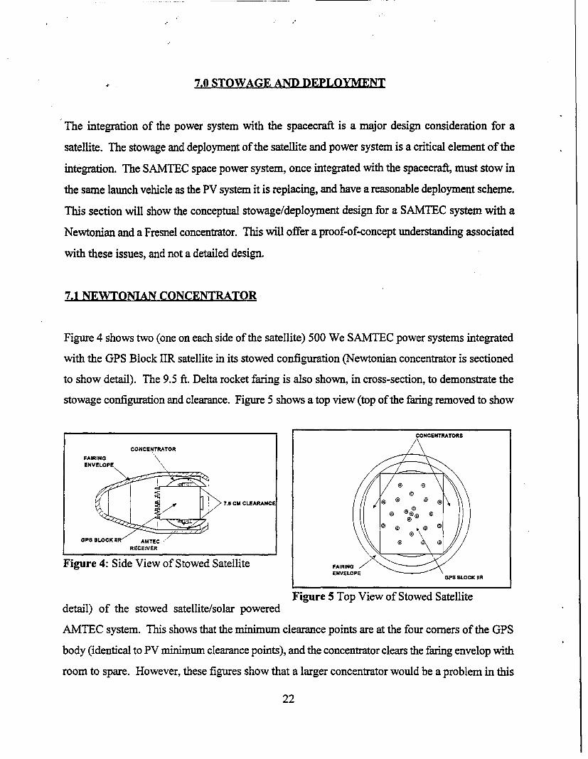
Figure 4 shows two (one on each side of the satellite) 500 We SAMTEC power systems integrated
with the GPS Block 1IR satellite in its stowed configuration (Newtonian concentrator is sectioned
to show detail). The 9.5 ft. Delta rocket faring is also shown, in cross-section, to demonstrate the
stowage configuration and clearance. Figure 5 shows a top view (top of the faring removed to show
CONCENTRATORS
CONCENTRATOR
FAIRINGENVELOPE \
OSBLOCK 11 AMTECZRECEIVER
Figure 4: Side View of Stowed Satellite FAIRINGENVELOPE
OPS BLOCK OR
Figure 5 Top View of Stowed Satellitedetail) of the stowed satellite/solar powered
AMTEC system. This shows that the minimum clearance points are at the four comers of the GPS
body (identical to PV minimum clearance points), and the concentrator clears the faring envelop with
room to spare. However, these figures show that a larger concentrator would be a problem in this
22
configuration and a different stowage/deployment scheme would be required. There are several
options such as; sunflower, spline radial, folding petal that could be looked at if the concentrator size
'increased.
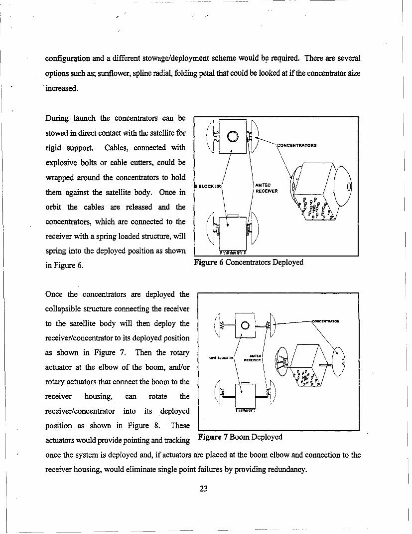
During launch the concentrators can be
stow ed in direct contact w ith the satellite for o-CO CENTA.O.rigid support. Cables, connected with CONcENTRToR
explosive bolts or cable cutters, could be
wrapped around the concentrators to holdBLOCK IIR AMTEC
them against the satellite body. Once in BO RCJR EIV
orbit the cables are released and the
concentrators, which are connected to the
receiver with a spring loaded structure, will
spring into the deployed position as shown I
in Figure 6. Figure 6 Concentrators Deployed
Once the concentrators are deployed the
collapsible structure connecting the receiver
to the satellite body will then deploy the oNCE--AT,receiver/concentrator to its deployed position
as shown in Figure 7. Then the rotary oo *LOC 11R AU
actuator at the elbow of the boom, and/or
rotary actuators that connect the boom to the
receiver housing, can rotate the
receiver/concentrator into its deployed
position as shown in Figure 8. These
actuators would provide pointing and tracking Figure 7 Boom Deployed
once the system is deployed and, if actuators are placed at the boom elbow and connection to the
receiver housing, would eliminate single point failures by providing redundancy.
23
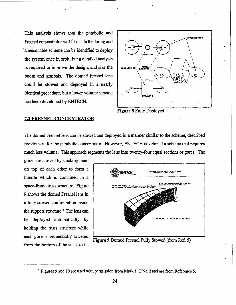
This analysis shows that the parabolic and
Fresnel concentrator will fit inside the faring and
a reasonable scheme can be identified to deploy
the system once in orbit, but a detailed analysis
is required to improve the design, and size the cpsLOc, l ECEIVER.
boom and gimbals. The domed Fresnel lens
could be stowed and deployed in a nearly "
identical procedure, but a lower volume scheme
has been developed by ENTECH.
Figure 8 Fully Deployed
7.2 FRESNEL CONCENTRATO
The domed Fresnel lens can be stowed and deployed in a manner similar to the scheme, described
previously, for the parabolic concentrator. However, ENTECH developed a scheme that requires
much less volume. This approach segments the lens into twenty-four equal sections or gores. The
gores are stowed by stacking them
on top of each other to form a * ncI,
bundle which is contained in a
space-frame truss structure. Figure_ . , , ,C. eeI , ."e TeL- o GE r r.... Pire
9 shows the domed Fresnel lens in
it fully stowed configuration inside
the support structure.2 The lens can
be deployed automatically by gr" ..
holding the truss structure while
each gore is sequentially loweredFigure 9 Domed Fresnel Fully Stowed (from Ref. 5)
from the bottom of the stack to its
2 Figures 9 and 10 are used with permission from Mark J. OrNeill and are from Reference 5.
24
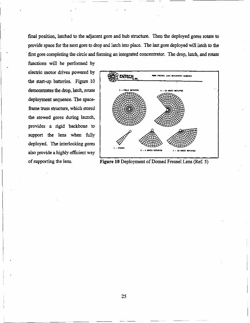
final position, latched to the adjacent gore and hub structure. Then the deployed gores rotate to
provide space for the next gore to drop and latch into place. The last gore deployed will latch to the
first gore completing the circle and forming an integrated concentrator. The drop, latch, and rotate
functions will be performed by
electric motor drives powered by FEESI. L,, .
the start-up batteries. Figure 10
demonstrates the drop, latch, rotate ,-F I,,'., 4, .- 10 G BC £4.1
deployment sequence. The space-
frame truss structure, which stored
the stowed gores during launch,
provides a rigid backbone to
support the lens when fyu
deployed. The interlocking gores 'O
also provide a highly efficient way - -6 O- 10 T,,
of supporting the lens. Figure 10 Deployment of Domed Fresnel Lens (Ref. 5)
25
&0 SAMTECDEVELOPMENT AND PRODUCTION COST ESTIMATES
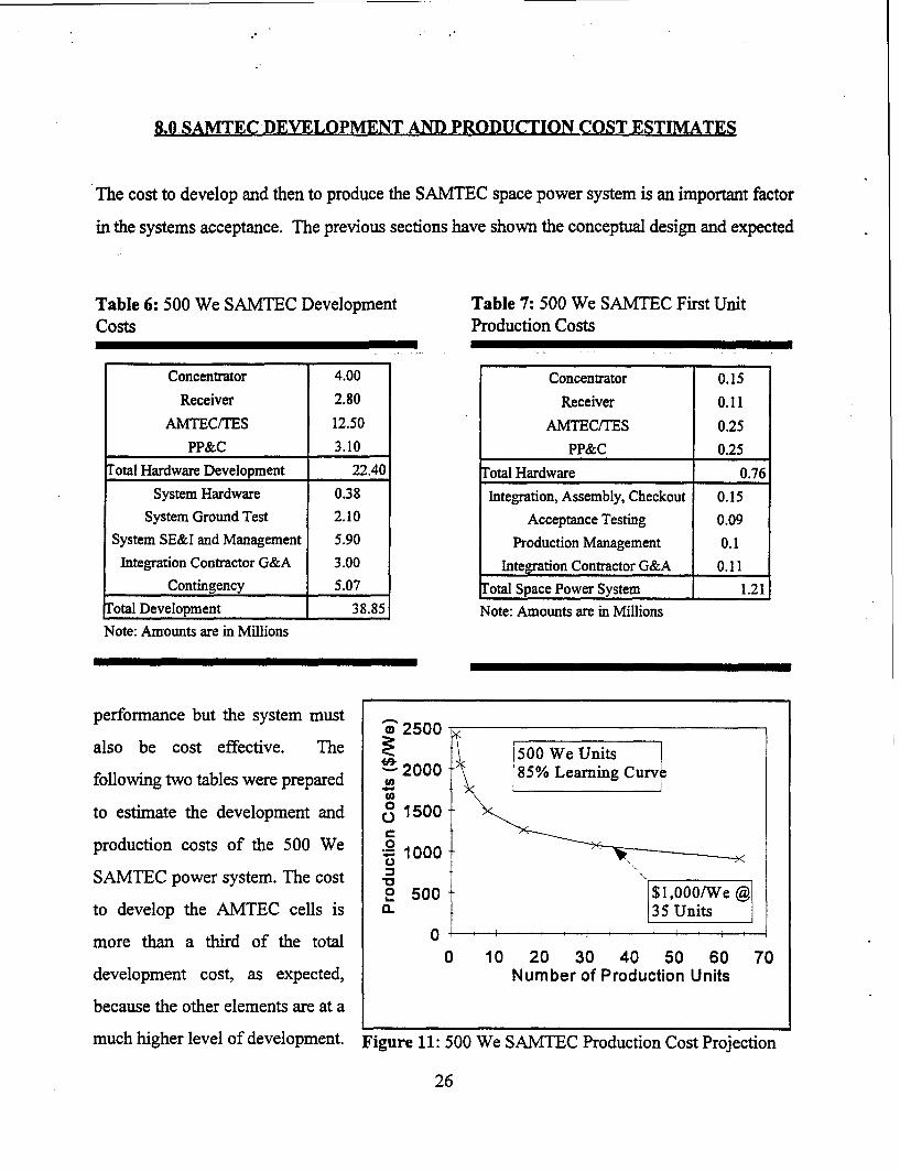
The cost to develop and then to produce the SAMTEC space power system is an important factor
in the systems acceptance. The previous sections have shown the conceptual design and expected
Table 6: 500 We SAMTEC Development Table 7: 500 We SAMTEC First UnitCosts Production Costs
Concentrator 4.00 Concentrator 0.15Receiver 2.80 Receiver 0.11
AMTEC/TES 12.50 AMTEC/TES 0.25PP&C 3.10 PP&C 0.25
Total Hardware Development 22.40 Total Hardware 0.76System Hardware 0.38 Integration, Assembly, Checkout 0.15
System Ground Test 2.10 Acceptance Testing 0.09System SE&I and Management 5.90 Production Management 0.1Integration Contractor G&A 3.00 Integration Contractor G&A 0.11
Contingency 5.07 kotal Space Power System 1.21Total Development 38.85 Note: Amounts are in MillionsNote: Amounts are in Millions
performance but the system must w"2500-
also be cost effective. The . 500 We Units2000 85% Learning Curve
following two tables were prepared £ 2
to estimate the development and 0 1500
production costs of the 500 We . 1000SAMTEC power system. The cost
2 500 $1,000/We @to develop the AMTEC cells is 0. 35 Units
more than a third of the total 0 i I0 10 20 30 40 50 60 70
development cost, as expected, Number of Production Units
because the other elements are at a
much higher level of development. Figure 11: 500 We SAMTEC Production Cost Projection
26
However, once the development is completed and production begins the AMTEC/TES should
conservatively cost $500/We. The initial system would costs $2,420/We and the goal of $1,000/We
will be reached at the 35 unit production level, assuming a learning curve of 85% as shown in Figure
10. At this level, the AMTEC system would be approximately a factor of 10 below PV systems with
comparable performance.
27
9.0 SAMTEC PERFORMANCE CHARACTERISTICS
The well established, conventional choice for LEO solar power is photovoltaic conversion with
batteries for energy storage. The Phase I program compared the predicted performance, cost, energy
storage mass, degradation, and lifetime/reliability of the SAMTEC system to PV/battery systems.
This section covers the comparisons made during the Phase I program.
9.1 SPECIFIC POWER
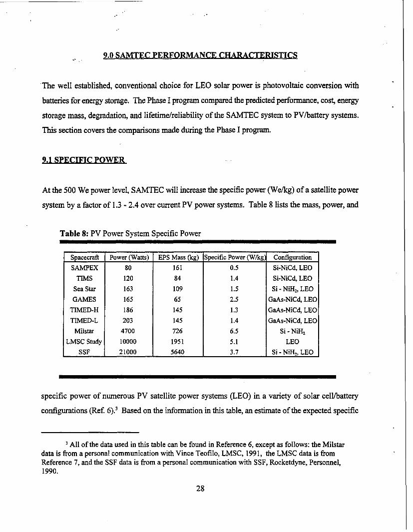
At the 500 We power level, SAMTEC will increase the specific power (We/kg) of a satellite power
system by a factor of 1.3 - 2.4 over current PV power systems. Table 8 lists the mass, power, and
Table 8: PV Power System Specific Power
Spacecraft Power (Watts) EPS Mass (kg) Specific Power (W/kg) Configuration
SAMPEX 80 161 0.5 Si-NiCd, LEO
TIMS 120 84 1.4 Si-NiCd, LEO
Sea Star 163 109 1.5 Si - NiH2, LEO
GAMES 165 65 2.5 GaAs-NiCd, LEO
TIMED-H 186 145 1.3 GaAs-NiCd, LEO
TIMED-L 203 145 1.4 GaAs-NiCd, LEO
Milstar 4700 726 6.5 Si - NiH2
LMSC Study 10000 1951 5.1 LEO
SSF 21000 5640 3.7 Si - NiH,, LEO
specific power of numerous PV satellite power systems (LEO) in a variety of solar cell/battery
configurations (Ref. 6).? Based on the information in this table, an estimate of the expected specific
3 All of the data used in this table can be found in Reference 6, except as follows: the Milstardata is from a personal communication with Vince Teofilo, LMSC, 1991, the LMSC data is fromReference 7, and the SSF data is from a personal communication with SSF, Rocketdyne, Personnel,1990.
28
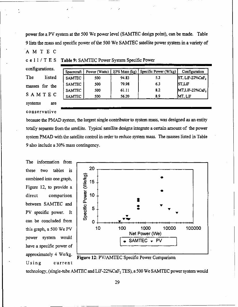
power for a PV system at the 500 We power level (SAMTEC design point), can be made. Table
9 lists the mass and specific power of the 500 We SAMTEC satellite power system in a variety of
AMTE C
c e 11 / T E S Table 9: SAMTEC Power System Specific Power
configurations. Spacecraft Power (Watts) EPS Mass (kg) Specific Power (W/kg) Configuration
The listed SAMTEC 500 94.83 5.3 ST, LiF-22%CaF2
masses for the SAMTEC 500 79.98 6.3 STLiFSAMTEC 500 61.11 8.2 MTLiF-22%CaF 2
S A M T E C SAMTEC 500 56.20 8.9 MT, LiF
systems are
conservative
because the PMAD system, the largest single contributor to system mass, was designed as an entity
totally separate from the satellite. Typical satellite designs integrate a certain amount of the power
system PMAD with the satellite control in order to reduce system mass. The masses listed in Table
9 also include a 30% mass contingency.
The information from
these two tables is 20
combined into one graph, 1 015
Figure 12, to provide a
direct comparison 1000-between SAMTEC and 0 5 •
PV specific power. It
can be concluded from Co 0 11 : i
this graph, a 500 We PV 10 100 1000 10000 100000Net Power (We)
power system would N PAMeC (WeV
have a specific power of
approximately 4 We/kg. Figure 12: PV/AMTEC Specific Power Comparison
Using current
technology, (single-tube AMTEC and LiF-22%CaF2 TES), a 500 We SAMTEC power system would
29
have a specific power of 5.3 We/kg, 1.3 times higher than that of the PV system. With the
improvements in the technology, (multi-tube AMTEC and LiF TES), the SAMTEC system would
have a specific power of 2.4 We/kg, a factor of 4 higher than the PV system, an overall mass saving
of-68 kg.
Using the models developed for analyzing the 500 We SAMTEC system (described in section 3 of
this report), an estimate of the specific power for larger SAMTEC systems was completed. Figure
12 shows that at the 5,000 We power level the SAMTEC system is estimated to be 12 We/kg (single-
tube LiF-22%CaF2) and 17 We/kg (multi-tube LiF). The Phase I results show that SAMTEC
systems offer high specific power at a low cost. The SAMTEC system also provides low
degradation, long lifetime, and access to all orbits (all of which will be discussed in detail later in
this section).
9.2 SYSTEM COST
AMTEC solar powered systems offer a low cost alternative to PV power systems, $1,000/We for
AMTEC compared to $5,000 - $10,000/We for PV, and the cost savings is inherent in the AMTEC
system. The overall cost for PV systems is not driven by the individual PV cell cost, but rather the
complexity of manufacturing the arrays (arrays are assemblies of modules, each comprised of a
number of parallel strings which are, in turn, sets of series connected individual cells). In spite of
this cost differential for GaAs cells, cost studies indicate that system costs are lowered by using the
more expensive, but higher efficiency, GaAs cells.' This indicates that the cost of individual PV
cells is not the driver of overall PV system cost, and that lowering cell cost will not substantially
reduce the overall system cost. The high system cost for PV cells can be attributed to the sheer
numbers required (300 - 400 for 500 We), the hand assembly (securing them to the structure with
adhesive and soldering the connections) of each individual cell into strings, modules and arrays to
'Discussions with Mike Piszczor at LeRC indicate that space qualified silicon PV cells cost
approximately $60/We, and GaAs cells are approximately $200-$300/We.
30
make a system, and the cost of qualifying each individual cell and its connections. The addition of
a cover glass to reduce the radiation degradation, and the use of cascaded cells to enhance efficiency
and reduce the number of cells required, also increases the mass and complexity; thus further
increasing the major cost factor and the specific power.
By understanding why PV systems cost so much, it can be seen why the AMTEC system will cost
significantly less. Given that the materials used to manufacture AMTEC cells are abundant and
inexpensive, (stainless steel and alumina), and that the manufacturing process can be relatively
simple (similar to vacuum or television tubes), the $1 00/We predicted for the production cost of
individual AMTEC cells appears to be reasonably conservative. Even though AMTEC cells, at
efficiencies equivalent to that of GaAs cells (19%), will cost 2 to 3 times less, this alone will not
provide a significant system cost savings because the individual cell cost is not the key to lower
system costs. Simply increasing the power/basic unit can reduce the assembly costs significantly.
The higher power of current single-tube AMTEC, compared to PV cells, reduces the required
number of cells from 300 to 400 - approximately 100. Even if equally complex manufacturing
techniques are used, the system cost would be lower by a factor of 3 to 4. If the advanced multi-tube
AMTEC cell designs are used, it would lower the module assembly cost by a factor of 12 to 15.
AMTEC cells should also be easier to integrate into a system than PV cells. AMTEC cells can bolt
into the system, with no adhesive as required for PV cells, and electrical connections that do not
require the delicate soldering of PV arrays. Taking all of these effects into account, we estimate that
a SAMTEC system (includes concentration, conversion, energy storage, and PMAD) should cost
less than $1,000/We.
9.3 ENERGY STORAGE
The most massive component in current space power systems is the energy storage subsystem. The
SAMTEC system has the ability to use either batteries or a Phase Change Material (PCM) to store
the energy needed for eclipse periods. The PCM uses the latent heat of the solid/liquid phase change
for storing the energy needed for eclipse periods. Figure 13 directly compares current stat-of-the-art
31
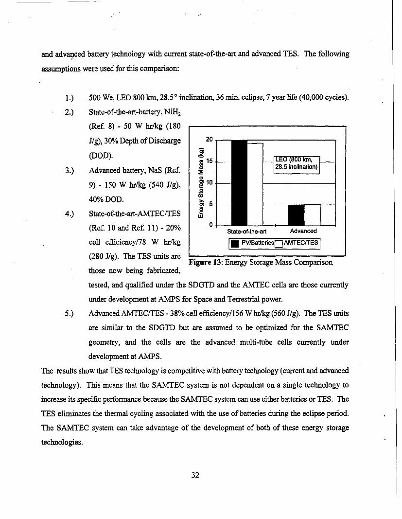
and advanced battery technology with current state-of-the-art and advanced TES. The following
assumptions were used for this comparison:
1.) 500 We, LEO 800 kin, 28.5 0 inclination, 36 min. eclipse, 7 year life (40,000 cycles).
2.) State-of-the-art-battery, NiH2
(Ref. 8) - 50 W hr/kg (180
J/g), 30% Depth of Discharge 20
(DOD). 15 -
28. ncinatin]h)3.) Advanced battery, NaS (Ref. 7-
09) - 150 W hr/kg (540 J/g), T l
40% DOD. >.-0
4.) State-of-the-art-AMTEC/TES t
(Ref. 10 and Ref. 11) - 20% State-of-the-art Advanced
cell efficiency/78 W hr/kg * PV/Battees[-] AMTEC/TES
(280 J/g). The TES units areFigure 13: Energy Storage Mass Comparison
those now being fabricated,
tested, and qualified under the SDGTD and the AMTEC cells are those currently
under development at AMPS for Space and Terrestrial power.
5.) Advanced AMTEC/TES - 38% cell efficiency/156 W hr/kg (560 J/g). The TES units
are similar to the SDGTD but are assumed to be optimized for the SAMTEC
geometry, and the cells are the advanced multi-tube cells currently under
development at AMPS.
The results show that TES technology is competitive with battery technology (current and advanced
technology). This means that the SAMTEC system is not dependent on a single technology to
increase its specific performance because the SAMTEC system can use either batteries or TES. The
TES eliminates the thermal cycling associated with the use of batteries during the eclipse period.
The SAMTEC system can take advantage of the development of both of these energy storage
technologies.
32
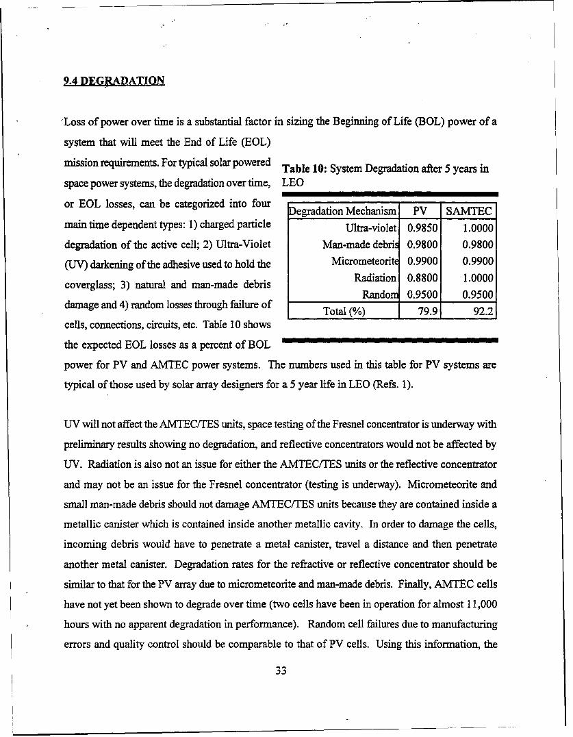
9.4 DEGRADATION
Loss of power over time is a substantial factor in sizing the Beginning of Life (BOL) power of a
system that will meet the End of Life (EOL)
mission requirements. For typical solar powered Table 10: System Degradation after 5 years in
space power systems, the degradation over time, LEO
or EOL losses, can be categorized into four egradation Mechanism PV SAMTEC
main time dependent types: 1) charged particle Ultra-violet 0.9850 1.0000
degradation of the active cell; 2) Ultra-Violet Man-made debris 0.9800 0.9800
(UV) darkening of the adhesive used to hold the Micrometeorite 0.9900 0.9900
coverglass; 3) natural and man-made debris Radiation 0.8800 1.0000Random 0.9500 0.9500
damage and 4) random losses through failure of Tod (. 92.2Total (%) 1 79.91 92.21
cells, connections, circuits, etc. Table 10 shows
the expected EOL losses as a percent of BOL
power for PV and AMTEC power systems. The numbers used in this table for PV systems are
typical of those used by solar array designers for a 5 year life in LEO (Refs. 1).
UV will not affect the AMTEC/TES units, space testing of the Fresnel concentrator is underway with
preliminary results showing no degradation, and reflective concentrators would not be affected by
UV. Radiation is also not an issue for either the AMTEC/TES units or the reflective concentrator
and may not be an issue for the Fresnel concentrator (testing is underway). Micrometeorite and
small man-made debris should not damage AMTEC/TES units because they are contained inside a
metallic canister which is contained inside another metallic cavity. In order to damage the cells,
incoming debris would have to penetrate a metal canister, travel a distance and then penetrate
another metal canister. Degradation rates for the refractive or reflective concentrator should be
similar to that for the PV array due to micrometeorite and man-made debris. Finally, AMTEC cells
have not yet been shown to degrade over time (two cells have been in operation for almost 11,000
hours with no apparent degradation in performance). Random cell failures due to manufacturing
errors and quality control should be comparable to that of PV cells. Using this information, the
33
degradation of SAMTEC can be compared to that of PV systems. The SAMTEC should retain 92%
of its power level over a 5 year life. This low degradation allows selection of a small power system
resulting in low direct and indirect costs, and/or may increase the life of the satellite by increasing
the amount of propellant that can be carried.
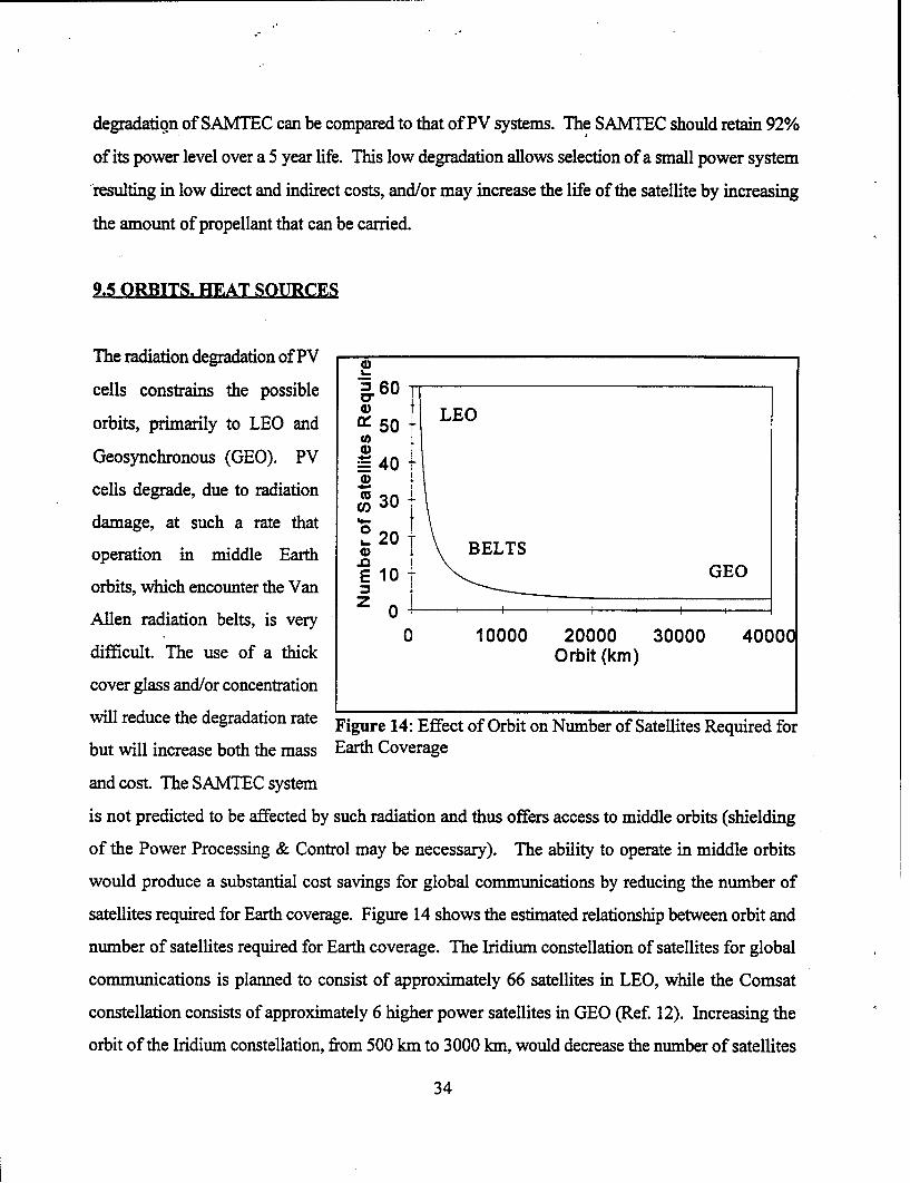
9.5 ORBITS. HEAT SOURCES
The radiation degradation of PV
cells constrains the possible =.60f LEO
orbits, primarily to LEO and X 50 tc)Geosynchronous (GEO). PV -4
cells degrade, due to radiation w 3 +damage, at such a rate that 0S-20 Tioperation in middle Earth BELTS
E 10orbits, which encounter the Vanz I
Allen radiation belts, is very 00 10000 20000 30000 40000
difficult. The use of a thick Orbit (kin)
cover glass and/or concentration
will reduce the degradation rate Figure 14: Effect of Orbit on Number of Satellites Required for
but will increase both the mass Earth Coverage
and cost. The SAMTEC system
is not predicted to be affected by such radiation and thus offers access to middle orbits (shielding
of the Power Processing & Control may be necessary). The ability to operate in middle orbits
would produce a substantial cost savings for global communications by reducing the number of
satellites required for Earth coverage. Figure 14 shows the estimated relationship between orbit and
number of satellites required for Earth coverage. The Iridium constellation of satellites for global
communications is planned to consist of approximately 66 satellites in LEO, while the Comsat
constellation consists of approximately 6 higher power satellites in GEO (Ref. 12). Increasing the
orbit of the Iridium constellation, from 500 km to 3000 kIn, would decrease the number of satellites
34
required for full coverage to approximately 16 satellites, 4 times lower. The cost of the satellites in
the higher orbit would be higher due to increased power requirements, complexity, etc. However,
even if the cost of the higher orbit satellites were twice that of the LEO units, the cost savings for
the constellation would still be approximately 50%, a significant net savings considering the cost of
a satellite constellation.
The total market volume and the cost reduction available from high volume production of space and
terrestrial PV systems is limited by the single, unreliable (insolation on the Earth is unreliable) heat
source required to operate the cells. AMTEC systems can operate with any heat source of sufficient
temperature (solar, combustion, nuclear, etc) which greatly increases the number of potential
commercial markets and makes AMTEC more cost effective (since costs are reduced for all
applications). Remote sites typically use combustion heated thermoelectric generators with an
overall system efficiency of approximately 2-5%. PV systems are also used for some remote site
power sites and offer substantial gains in efficiency over thermoelectric generators but cannot
operate during bad weather and at night, or require a supplemental fuel-fired generator system or
batteries. An AMTEC system could offer the best features of both systems by providing a single
system with efficiency comparable to, or better than, PV systems and the capability of operating
independently of the solar insolation with a single converter. According to Lamp and Donovan (Ref.
14), by doubling the efficiency of the converter in a propane-fired generator the United States Air
Force (USAF) would save approximately $3 million per year for just two remote sites. Considering
the total number of such sites operated by the USAF, the total savings could be in the hundreds of
millions of dollars per year. Current AMTEC cells, 18% efficiency, more than double the efficiency
of the thermoelectric units presently used in propane-fired generators (Ref. 11).
9.6 LIFETIME/RELIABILITY
The SAMTEC power system is expected to have a long life and high degree of reliability. The
AMTEC system uses a PCM, with an anticipated life of 10 years, for TES during eclipse periods
(but could use batteries). The selected TES modules are being developed under the SDGTD at
35
NASA LeRC and test specimens comprised of 24 TES canisters have been successfully tested in
vacuum. There are four lifetime issues associated with the TES system; 1) cyclic stress due to the
phase change (expansion and contraction); 2) rupture of the canister due to void formation and
ratcheting; 3) corrosion of the canister due to exposure to the PCM, and 4) canister material loss due
to operation at high temperature in a vacuum. The test specimens were successfully run for
approximately 1500 hr (1000 freeze/thaw cycles) at temperature (767°C) in a vacuum to demonstrate
the resistance to cyclic stress (Ref. 10). There were two separate heater locations used during this
test to simulate the extreme melt orientations of the receiver, and test the resistance and effect of
void formation on the TES. The canisters are designed with rounded edges to eliminate areas of
stress concentration where ratcheting could cause failure. Test results have also shown that
corrosion between the PCM and canister is not a life limiting issue and does not result in a
degradation mode. These studies included the compatibility of three materials (HA 188, HA 230,
and IN 617) with the LiF-22%CaF 2 in air at 1073 K for up to 22,000 hours and in vacuum for up to
10,000 hours (Ref. 13). The TES is projected to have a very high reliability, long lifetime, and no
long term degradation mode is anticipated.
There are no identified degradation mechanisms for the AMTEC cells, and two AMTEC cells,
currently being life tested at AMPS in air, have operated for approximately 11,000 hours with no
apparent degradation in performance. Consequently, the AMTEC cells are also expected to have a
very high reliability and long lifetime and no long term degradation is expected.
The reflective and refractive concentrators are expected to degrade with time due to the space
environment. This degradation will be in the form of damage to the reflective or refractive surfaces
with a reduction in the efficiency of the concentrator. The amount of degradation will be small,
approximately a 5% drop in performance over a 10 year lifetime.
The reliability and lifetime for the remainder of the system (structure, PP&C, and deployment) are
expected to be similar to that of a PV system. SAMTEC could have a finer pointing requirement
(pointing accuracy better than ± 1 0 if a secondary concentrator is not used) than PV systems but this
36
is well within the current state-of-the-art. A secondary concentrator could also be used to "loosen"
the pointing requirements to approximately ±5 * if necessary. The smaller planform area of the
SAMTEC system will also lower the aerodynamic drag in LEO thus reducing propellant
consumption and increasing satellite lifetime in orbit if propellant consumption and/or station
keeping are the limiting mechanisms.
37
10.0 REFERENCES
Conference Proceedings
1. Kimber, R., and C. Goodbody, "Acheiving the Optimum Solar Array Size for
Spacecraft", Proceedings of the 29 h Intersociety Energy Conversion Engineering
Conference, Vol 1, pp. 267-271, Aug 1994.
JornArtigle
2. "Solar Radiation Strikes another Blow to ETS-6", Aviation Week & Space Technology,
p. 66, October 3, 1994.
Conference Proceedings
3. Determan, W.R., J. Emmons, F.N. Huffman, J. Dunlay, D. Worthman, and G. Field,
"Multi-Foil Thermal Insulation for the Dynamic Isotope Power System", Proceeding of
the 2 4'h Intersociety Energy Conversion Engineering Conference, Vol. 2, pp. 1115-1120,
1989.
Reference Book
4. Spiegel, M.R., "Mathematical Handbook of Formulas and Tables", Schaum;s Outline
Series in Mathematics McGraw-Hill Book Company, 1968.
NASA Technical Report
5. O'Neill, M.J., A.J., McDanal, and Don H. Spears, "Conceptual Design of a 5 Kilowatt
Solar Dynamic Brayton Power System Using a Dome Fresnel Lens Solar Concentrator",
38
NASA Contractor Report 185134 prepared under Contract Number NAS3-24877.
Technical Workshop
6. Small Spacecraft Technology Workshop: Technical Presentations, NASA Conference
Publication 10125, Pasadena, California, September 21-24, 1993.
Technical Reprt
7. Space Surveillance and Tracking System, Nuclear Reactor Power Source Integration
Report, August 1988, LMSC-F065917.
Conference Proceedings
8. Coates, D.K., and C. L. Fox, "Current Status of Nickel-Hydrogen Battery Technology
Development", Proceedings of the 2 9 h Intersociety Energy Conversion Engineering
Conference, Vol. 1, pp. 75-80, 1994.
Conference Proceedings
9. Phone conservation with Jim DeGrusson (working on NaS battery development) of
Eagle-Pitcher.
Conference Proceedings
10. Strumpf, H.J., et al, "Fabrication and Testing of the Solar Dynamic Ground Test
Demonstrator Heat Receiver", Proceeding of the 29h Intersociety Energy Conversion
Engineering Conference, Vol. 1, pp. 372-129, 1994.
39
Conference Proceedings
11. Ivanenok III, J.F., R.K. Sievers, and C. J. Crowley, 1995, "Thermal Modeling of High
Efficiency AMTEC Cells," Proceedings of the 24th National Heat Transfer Conference.
Journal Article
12. SPACE NEWS, Oct 3-9, Vol 5, No 37, 1994.
Journal Article
13. Whittenburger, J.D., "Effect of Long-Term 1093 K Exposure to air and Vacuum on the
Structure of Several Wrought Super Alloys", JMEPEG (1993) 2:745-758.
Conference Proceedings
14. Lamp, T.R., and B.D. Donovan, "Unattended Power Sources for Remote, Harsh
Environments," Proceeding of the 29th Intersociety Energy Conversion Engineering
Conference, American Institute of Aeronautics and Astronautics, Washington, D.C.,
1994, Vol 2, pp. 688-693.
40
11.0 NOMENCLATURE
AMPS Advanced Modular Power Systems, Inc.
AMTEC Alkali Metal Thermal to Electric Conversion
AO Atomic Oxygen
BOL Beginning of Life
DOD Depth of Discharge
EOL End of Life
GaAs Gallium Arsenide PV cells
GEO Geosynchronous orbit
GPS Global Positioning Satellite
InSTEP In Space Technology Experiment Program
LEO Low Earth Orbit
LeRC NASA Lewis Research Center
MEO Middle Earth Orbit
MLI Multi-Layer Insulation
NaS Sodium Sulfur
NASA National Aeronautics and Space Administration
NiCd Nickel-Cadmium battery
NiH2 Nickel-Hydrogen battery
PCM Phase Change Material
PMAD Power Management and Distribution
PP&C Power Processing and Control
PV PhotoVoltaic cells
SAMTEC Solar AMTEC
SBIR Small Business Innovative Research
SDGTD Solar Dynamic Ground Test Demonstration
Si Silicon PV cells
TES Thermal Energy Storage
41
USAF United States Air Force
UV Ultra-Violet ray
We Watt Electric
42
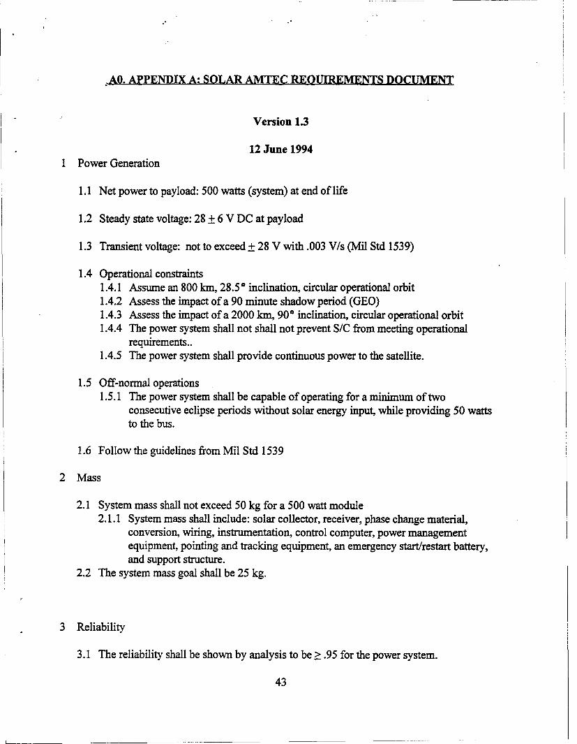
-AO. APPENDIX A: SOLAR AMTEC REQUIREMENTS DOCUMENT
Version 1.3
12 June 1994
1 Power Generation
1.1 Net power to payload: 500 watts (system) at end of life
1.2 Steady state voltage: 28 ± 6 V DC at payload
1.3 Transient voltage: not to exceed +28 V with .003 V/s (Mil Std 1539)
1.4 Operational constraints1.4.1 Assume an 800 1In, 28.5 * inclination, circular operational orbit1.4.2 Assess the impact of a 90 minute shadow period (GEO)1.4.3 Assess the impact of a 2000 km, 90 * inclination, circular operational orbit1.4.4 The power system shall not shall not prevent S/C from meeting operational
requirements..1.4.5 The power system shall provide continuous power to the satellite.
1.5 Off-normal operations1.5.1 The power system shall be capable of operating for a minimum of two
consecutive eclipse periods without solar energy input, while providing 50 wattsto the bus.
1.6 Follow the guidelines from Mil Std 1539
2 Mass
2.1 System mass shall not exceed 50 kg for a 500 watt module2.1.1 System mass shall include: solar collector, receiver, phase change material,
conversion, wiring, instrumentation, control computer, power managementequipment, pointing and tracking equipment, an emergency start/restart battery,and support structure.
2.2 The system mass goal shall be 25 kg.
3 Reliability
3.1 The reliability shall be shown by analysis to be > .95 for the power system.
43
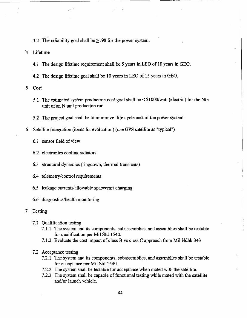
3.2 The reliability goal shall be > .98 for the power system.
4 Lifetime
4.1 The design lifetime requirement shall be 5 years in LEO of 10 years in GEO.
4.2 The design lifetime goal shall be 10 years in LEO of 15 years in GEO.
5 Cost
5.1 The estimated system production cost goal shall be < $1000/watt (electric) for the Nthunit of an N unit production run.
5.2 The project goal shall be to minimize life cycle cost of the power system.
6 Satellite Integration (items for evaluation) (use GPS satellite as "typical")
6.1 sensor field of view
6.2 electronics cooling radiators
6.3 structural dynamics (ringdown, thermal transients)
6.4 telemetry/control requirements
6.5 leakage currents/allowable spacecraft charging
6.6 diagnostics/health monitoring
7 Testing
7.1 Qualification testing7.1.1 The system and its components, subassemblies, and assemblies shall be testable
for qualification per Mil Std 1540.7.1.2 Evaluate the cost impact of class B vs class C approach from Mil Hdbk 343
7.2 Acceptance testing7.2.1 The system and its components, subassemblies, and assemblies shall be testable
for acceptance per Mil Std 1540.7.2.2 The system shall be testable for acceptance when mated with the satellite.7.2.3 The system shall be capable of functional testing while mated with the satellite
and/or launch vehicle.
44
8 Launch Segment
8.1 Shock and vibration
8.2 Launch vehicle integration8.2.1 Stowed volume and configuration8.2.2 Mating points
8.3 Launch operations
8.3.1 Hold on pad
9 Ground Handling
9.1 Transportation
9.2 Storage
9.3 Physical handling
10 Safety
10.1 Hazardous material containment
10.2 Flammable material containment
10.3 Personnel hazards10.3.1 Thermal10.3.2 Electrical
11 Physical Configuration
11.1 Stowed configuration11.1.1 compatible with MLV11.1.2 compatible with Pegasus/Taurus
11.2 Deployed Configuration
45
B.0 APPENDIX B: SAMTEC COM[PUTER CODE LISTING
46
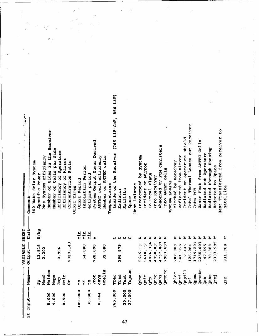
in
U 0p
>0
0 V in 4)0
4) 0 rj0 r-4 .-0 N H 00 4J p4 -4)
10 4) m 0 CJ2I 3 r. 00) Nq p 4 4 0 di-t4 0
A n >1.C2 w~ 0) 0 N4 UN) $4.)J 4-i ' $40.4 > al 0N p m W :
p m ( 0O 0 ~ -$40 4 4.) kNN 0 E-4 4i 0 20) 4 34 0~ N -- 000 0) 4N It) M $ dP JO M (U 04i. r -r 4 4)$44J V0 '-HC 0 >1 0 >) >--i U (a ONk0 0 0 4 -H (d 0 00 0 k - 0 4) AN U~ 044>1 -r M m 4 i-.U $4 N Wr4 0~ 4 m al03 14 44 0, NVj 44Wr >1 -H 0 u v-I 0 UEOEm c
w 'o t-4Qw w a) 00 4J 44 E-4 0) 9! NQ 4 0 0O~ N - 0 u20W z -r4)0 0 O p V~-r:34)0 A c0 U 0 wN (d 4-I-I NJ 4
rd 0 o U -"H 0 pNP 41 -> m 4 aS :J. 0 4
r 0 6 >1 >1 41 *r. 4)4.)-4 m 04 00~4 qkU a)>1 ONp 410 4.)111WO a 044 44 00 dM P0 P4 3-I 44 (D 4 0 41 0 W 0 .01 4 4-JO)U2C)4J 0 0 ~0g:p0 4 -H 0 )0O40N4O P 1 0-1 0-IUV -40 m J1 l .
-A a)d)4.) S 4 4)0 a) j 0 41 .' L 0 ( 0 W 0 10 U V)-J)-4C))000 -A.i 44 >1NN-r4-ri- g3o rj 0m N44J ()4J -H r-I 0 0 )u9 . 4 .. 0 0 0 0 4J 4.) 4.) ( r-
9: (dV -H ri r. 'rq -H ' NW-A 4 - - 4 E) C 0 -H N 0 00 S20 - -.4 4J O -q-,1 4) Ef4 0)(D 4 4 44449:4.)A e M -4F=0 0 4J C 4110r 4 4J Q) 0 4 U4-) 4. M 10--j 4
00 N Z W W1 0 00ZC dHH& Q0 - C91 X(
UU10 E-4
E-4
covq r t Hr.r Hr- r% l
rz w 0 0 0 0enM (n ci ~0 a oo w w m 012 - 1 W T-4 0 0 0 *- -I elC *% DH wco(4% hC 7
4Jr(i~ w~~i O 0
M Nl 10 CD Cli N 4llr mco rHUiwI L - c mi -4.1 fO 0 CD %D N m c% CC Go rD- (A 0~ qccq Z-0 E- . 1 . l
z n tn ('4 i ir v "t c N'1L r. r-4 Cq N' ch
> 0 -
0 -I d) 0 U r4I 4J.0) 4.IV Njw 4J M -4 4J.I 0 4J N 0 M 4) 0 44-,1r m0 Mis 4 H04jai 0 >10 0 U0 Q 9 4P44 4 4) 04 0jHULU(a 44 ()IU pa m m u 2Nc 0 -r4OWJ4J NNOO m -riS 4E4-JN( .0 N4WNW jr0 J k -Hz ~z z z ww 4 43 4JJO 0 Z E4 E-4 E-4 0'O00'0 oboiobotoo'i Of
4J 0 0O N n o~0 0 %0 0 C; (r('
47
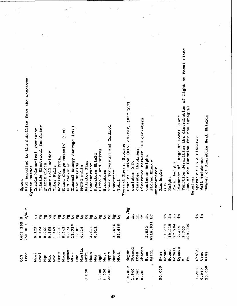
4J
4
0
4
E 0 (
0 -H 4040
444
E- 000$ ,q14-
fd i 0 0 0 0 $4 2
oo a)~0 Hn E-4 (d M r. S
4J Hr4r 040C ar :0 (*v. (a $4 .-) M CD m J 4.) V r
H 0.1.) ) 4) 1 > M d) MU Ar H 4J 44J ( uE -1. 10 OVm41 CJ4)m-HU(
-,q) $H H4 0d > a X 3 0 M .1 w 1 0 4 M i m 0~ 0 40 W0$ >,HE $4 0la(D 412 ui :9 0. 0 4$ 44 m > H , nM 0 0)11
-r n )4)4 M E4 )4) m rl0 V)1 4 ) 0 .0 .1J J 4 . . 0r- )a 2 4 r H r- 44 r ) P 0 4J w a 0a 0
04 M H r- W0- - dMW 4 - 0 $ )r j r ) 9 )E
w 1tom 4 :J. ) 04 C 4 '0$4 0J 02 -H 4H $4 4) 0 - WHO $4 )w q4 0 E Ii0 p 0 4 02 -I WMW J - 0 4J 0 0 'l )
o x roM $ 0 0 Dm 4 A- 4 d (d Cd 4. 0 -H 00f .Qd- -r 40 tl( -4 "1 4 4V HO : :S( 0 ) (d0PH 4 0 0 0CO( r- (d. 40 J U- -a 0 -'.4 0 040
CO 4$ 4MH00H090 4E4u0 H C )E)C .W :Z 054 IM Wl) 0 454 02
'.00J. 024G0~4C2 0 O04.4t0oH H JH 1JJ 0 1O4J 0$ 0V
S4 XE 0 l .9 9A x .i -4 -r 0 H -- -0102 frq 4H
C1 o ci v 0 cDc o4 wHJn% 00 r- w w. cl (7 -rI 00 " m .m H
>1 co r .N wH r 0 0 - C L - - mr ! c
0- E- Is 0U E )-
0 0
.-.- 0 0000000000 110 0 0 v 0101
LI)CH
a~o~ qoo M 48
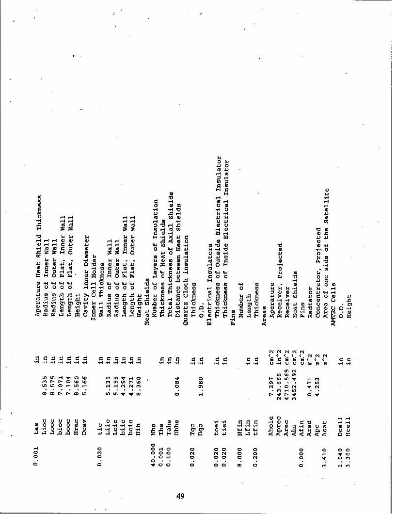
0 14
41 0
m H4)
0' r4V*-UC)~4 Hr-I 4H I COJ.
HH -IfI- HH H o 4 4J. CO ((- rIU r-4 H -H 4) V
E-4 2c z 0 HH O (a mUH 0 C)$4~s 1.) HH 5 I-H 0.v LVO 4. 4
,-0(0 0 09 4-i 0 44 04)CO -I 4 34J - 1 W -H mJJ 4) 140
to 1 .. .w.1 $44- 14 W0 gUd 0- . . 4
$4 -H 4 4$ 44 0 -3 I : 30)4Jd)4)4 4 I P $. 0~ 4) 4.) JJ..-l F)-14- 04 HCCH9: 4 Jx 0CH O CO r-0 M 0.40d O4 : . :
0 P4.4 44 0H).4-41- VI-1-r 5) 00 4 0) W 4) 900 000)$400Q I-I -r00 0 2. 0 HO Q 1-q 141 H0 00 -I-400 0 r- 0 00 0 m rC)H 0 000 04 40 04 $4JH
$4'4n l 1 -H wr- - H ) O A U COJ NC U 1 W )U yl05402.)M-r4C) U (2(L 0 V V. r H>4 01 -H -HV ~ 4J M J-H J.-4 -H r.-r4Wm 0C)0 U(dZro90 u "
Cd~~ ~ 0t HD V )-i.- d d4 )4) j. Hw40 d0 )0d -I 4W
(1 ( 4 e CV( 4~ C C 4(' C4 C4l
~v~'r4-l,4 .-- ,-,.v4-4-4 - -H. *r-H -4 -- i -r-I U H U u u ~ E r v4-
Ln c~4%D V ()
UnL riw oL l H 'vJ44rI 0 r- U HDL w -Mr r-0% %D mU*in Ln - % D C j% .~ r* C-nin in oHrILn r-i HHI feqNeN 0 (h4 *0 4 v Ne
CCCCC> C))CC m) -.*4-r4 4 HO) 4.) s-J HHm0200 00 0 ( " C-.-H -HI. m C)C 00 A *d.4 - 1 01 C0 w0)a0-- au d ato -10 -H0 w ) *Hv4,40 r4 0 -H 4 (a 0 0 04 4--W444 4 k 01 4 M 0 U
00
00* H 0 0 0 0o eq 0 m ~
49
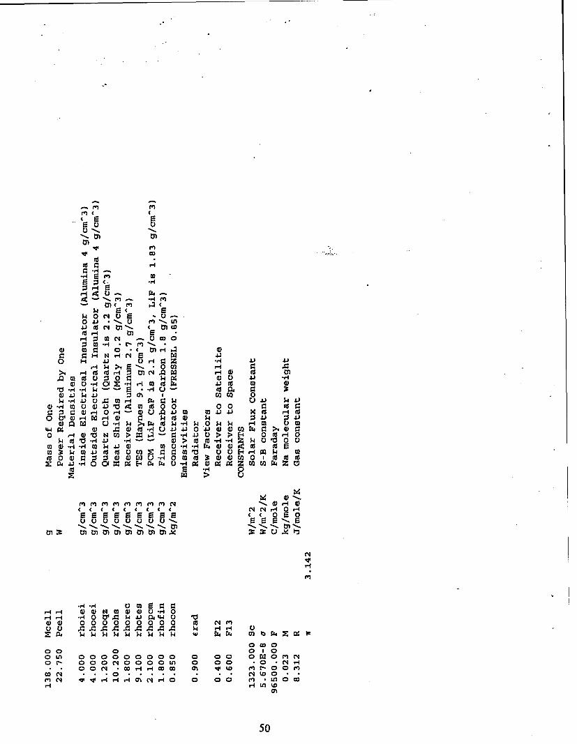
rn
.. 42 02
rzr0 4J - ME nIL
(D . 0' -0---r
-4 w 1 r: J0 c -
.0 m W ) 0 ( 2)i4 ~ 0 E 1
o J M 4.3 ;3 (~ 1.3 toc4- JU4 M1 40 $ E)5G 4 ) 02
.0 2d0 0 S.( E )43r ( 0 0 0 .3r.& C:( -4 0 Zr- 0) U .04J 4iJ42 cd 0- (
0 4J.4 0 I)02 0 - d 44 34W..4J,0r Qz~. W .UH 40w Hm0 3im E
4~4 X 04' 02 O 0L d-4U4 J04)W0 M 44 : i 2 :0 q01 / > 0A d . 0 54 )>> 0c -
0 r -r M E -4 0J d ) - I A ) 0 ( ( 4 2 r -4k M 2'..4. (d(dE M2:r 0 M 42(42E.4 r I m k.4 m
(a0 ( 0*, Z4025 4 ) U - 0 m (d 3:(L) 0) 0 1 to (a2Z ia,41 H 0 Ct =C4 - 0 )-H 0 X 9 ZM w N 0
N4 N 1.4 0 -
4(~ 0 s-0
M :MMMMeMOMMc4 2c : E r40
( ( ( ~( ( C C42r~40 N
222222 '- 020 m0
r-4 ,I4 0 N 0 t' 0W J 4 000W 000000000 (4 (14e00 U A 4A444 ri~ H0EE0j $4 4 W W W 4 4 .4. w aP4 r bC 1-
0 0 0 010o f3 00 0000 0 0 0 0 z0 MC N0~ 0 00 4000 o0fn 0 0 0 *0 N 'ri
0- 0 4 corI f c o hf
50
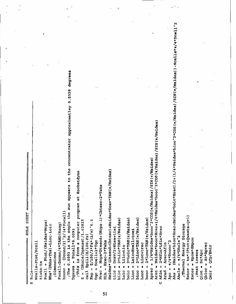
N(
..4
."4
L02
H
C;
>1=4)=
H
4.)4
02,-
Cd:s!
x0 02
'0
$4.
'0
In H
oto
O 0
H 'm0 W 0H2O
U 0
.4 0)m
0 .9'H3 0
Of X ca q
o - 0 4)
4) Ix 0- 1
O > ,-
0 ~ 0 $0 --- ,a €
111 544) NSi ) .0- m9
f o m Uro 4o p 0-
oi '00 Zn I H m m o 1
Cf) ~ ~ . 0 02 q C ) 4) 4 4rIz o
C.) tyl 44 i II 00 Ml f l vl f t l It n + l ,+ +l
r.2 0 4 r ~ . 1-- H -4 - - E)0 0 E H0
d)r 1,N N + d + Io = = = A IF= ° * 4.. ..
S-I
E514 0 4
11 * mrq 0 9 - 0 +W E9voElW'-4 4A P 0.U. 0r - =( - d +* 0* 1 -11 4 0* 4 )11 0 0 t)C * 0C4 0 J 04) )Z 0 In0p mU it
4JA MU 0 m 02 - , 1 m11- H+0+ 0 5H+E)d . 4
4J a m-i0 -0 m +- q' H.4 4)00 H* 0*0q* -ri4 n4III ~ ~ ~ W 020 al-'0- ,1 E 463.40 c 4C4 Z C, d n O
11 4J 02.11 I 0 0 0 3 : 1- 10 0- - ) y 1 1 0 0 It a 4 4 40d r
(1 1' fc . C02 4 Si 10 rir u9' )0 a ( ()L 0 r44 L .
P4 1 d)M U 0 E-4 M H 11 , ) 4 02- H H- 0 0 02 5 ) 4C 0 E-0 02 54' 0r-
0.4 , 1 ~1 M-I M IV ~ .. *4 "10 1r. 4- 4 4 1400 0 m Or .W.Z4)aZ N~r~ -.w 0 z.00 024 0 200 0 05.2444w fcn0 ~ * ~ ~ 04 Z ~ ~ 55 4 50
02 *. 0 EH-.'.. - 25i. Q.~~510
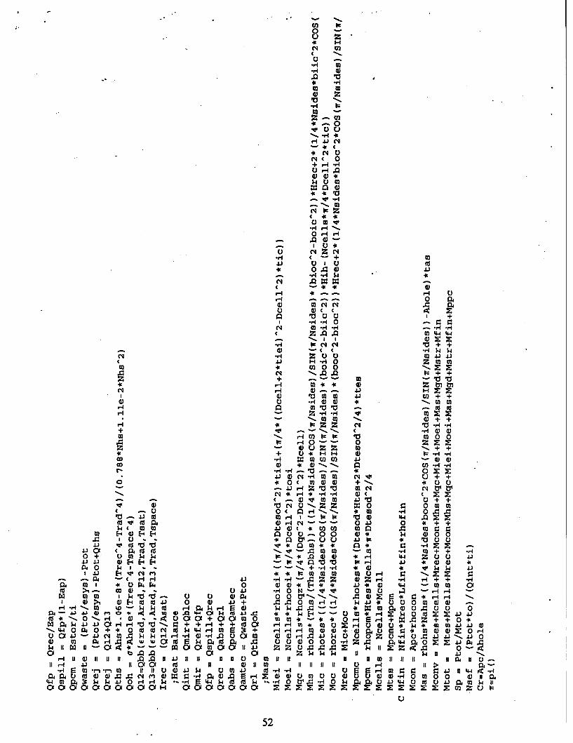
0 l
o M-H m
-H -
rI W
a) z
a,
* -0
(~ 0+. .rI -H
E) m
0~' 0
aa*
0 .- I *-I
A4)
0~ C0lC'
JJ 010
4~~ -* a
I 1 0 2 2a, W C4 1( ( - $ $
-i RI az m
Wr 4) (D1200m
H m 10 10 1.(a tdz H , vo Li (2 x
W, M *.0a .+ +~
+ -rl W, r 4)m 'w w I=I- 0m
t- - 0 2
r% 0~H a,
. r4.)4W -- mmU0 ( 0' 0) 4) +-. q U00
C4*~r4r E,) z ZE40 . 00 -* 0 -.. ,Io * H 0.
0 0 ) r4 N --- 01.) 0 *i + +
o E-4,-4 E-4 0 UE)-o 0U $ ) 4 D 0 01- I1 V '4 ~ ~ .* qt Q -iU 4
.).01 (a(av- .0W U3 *- M A ++ r40+ -) $44 k -,*4H - 4-4 zOUUO .
Ilio $4' 1 . ~+4 "1 a, I $4 w 4.
04 --( H- 1 .1- H W-HZ.0Z Z 0 ZH -i 1-+4 +~i I * 0i v 4 44 0 4) 0 E- ** 4 * ) 44I - wW 01GO WW) % $4 . E)0- 0 N VV 00-..-..- r- r-H '-
m a,> I w 10 V 0 a, 0 i+ 0 0 Ol0WHH S4 0.J S 0 0Wa a *--4) >4 W ED-4 004J 4 Hm4H a $4 --- H 4J 0 M 0 0
-jI. -r , m mQH 4 0A4. 0 E) $4 -''- E) HZ 04 Z j
Id . 0Q 0 00rl$ 4I W + HHH H4++a, o .4 Wa+a+ZOW O~i' 04 W4 4JH-- 4. C 0+ -I~ 00+ 0 a, a,-4 .L $400 oZ )2r- ) 0-- * w .3 .Aj 0)a, 40P40+ 0d~ ww0IUN2(d$4 4 rI M 3. + o o o-I .r- -oZZmv 8 z 4 )mo R4 . 4$ - -- )-4A E ~ )0 CII Z4 4 w U z $H 04J J - 4wI . 1100 11 II aU mIIaDUII zz 0 H I
Er rri 11i 4)s-$ 0o -1.-4.- 0SEW0 A4 If4) 1 11 0 m a m 1 1 111P 4E
" 00 Nm ZH 0H 00 U0 00010000m Z ZZZZZZZ0 0 U
52
DISTRIBUTION LIST
AUL/LSEBldg 1405 - 600 Chennault CircleMaxwell AFB, AL 36112-6424 1 C)'
DTIC/OCP8725 John J. Kingman Rd, Suite 0944Ft Belvoir, VA 22060-62 18 2 CYS
AFSAA/SAI1580 Air Force PentagonWashington, DC 20330-1580 1 C)'
PL/SULKirtland AFB, NM 871 17-5776 2 cys
PL/HOKirtland AFB, NM 87117-5776 1 C)'
Official Record CopyPL/VTP/Lt Randy Boswell 2 cys,Kirtland AFB, NM 87117-5776
PL/VT 1 cyDr WickKirtland AFB, NM 87117-5776
53/54
Related Documents