Welcome message from author
This document is posted to help you gain knowledge. Please leave a comment to let me know what you think about it! Share it to your friends and learn new things together.
Transcript

Chapter 3
Object-Oriented Design
A cursory explanation of object-oriented programming tends to emphasize thesyntactic features of languages such as C++ or Delphi, as opposed to their older,non object-oriented versions, C or Pascal. Thus, an explanation usually turnsrather quickly to issues such as classes and inheritance, message passing, andvirtual and static methods. But such a description will miss the most importantpoint of object-oriented programming, which has nothing to do with syntax.
Working in an object-oriented language (that is, one that supports inheri-tance, message passing, and classes) is neither a necessary nor su�cient condi-tion for doing object-oriented programming. As we emphasized in Chapters 1and 2, the most important aspect of OOP is the creation of a universe of largelyautonomous interacting agents. But how does one come up with such a system?The answer is a design technique driven by the determination and delegation ofresponsibilities. The technique described in this chapter is termed responsibility-
driven design.1
3.1 Responsibility Implies Noninterference
As anyone can attest who can remember being a child, or who has raised children,responsibility is a sword that cuts both ways. When you make an object (beit a child or a software system) responsible for speci�c actions, you expect acertain behavior, at least when the rules are observed. But just as important,responsibility implies a degree of independence or noninterference. If you tell achild that she is responsible for cleaning her room, you do not normally stand
1The past few years have seen a poli�eration of object-oriented design techniques. Seethe section on further reading at the end of this chapter for pointers to some of thealternatives. I have selected Responsibility-driven design, developed by Rebecca Wirfs-brock [Wirfs-Brock 1989b, Wirfs-Brock 1990] because it is one of the simplest, and it facilitatesthe transition from design to programming. Also in this chapter I introduce some of the nota-tional techniques made popular by the Uni�ed Modelling Language, or UML. However, spacedoes not permit a complete introduction to UML, nor is it necessary for an understanding ofsubsequent material in the book.
49

50 CHAPTER 3. OBJECT-ORIENTED DESIGN
over her and watch while that task is being performed{that is not the nature ofresponsibility. Instead, you expect that, having issued a directive in the correctfashion, the desired outcome will be produced.
Similarly, in the owers example from Chapter 1, when Chris gave the requestto the Florist to deliver owers to Robin, it was not necessary to stop to thinkabout how the request would be serviced. The orist, having taken on theresponsibility for this service, is free to operate without interference on the partof the customer Chris.
The di�erence between conventional programming and object-oriented pro-gramming is in many ways the di�erence between actively supervising a childwhile she performs a task, and delegating to the child responsibility for thatperformance. Conventional programming proceeds largely by doing somethingto something else{modifying a record or updating an array, for example. Thus,one portion of code in a software system is often intimately tied, by control anddata connections, to many other sections of the system. Such dependencies cancome about through the use of global variables, through use of pointer values, orsimply through inappropriate use of and dependence on implementation detailsof other portions of code. A responsibility-driven design attempts to cut theselinks, or at least make them as unobtrusive as possible.
This notion might at �rst seem no more subtle than the concepts of infor-mation hiding and modularity, which are important to programming even inconventional languages. But responsibility-driven design elevates informationhiding from a technique to an art. This principle of information hiding becomesvitally important when one moves from programming in the small to program-ming in the large.
One of the major bene�ts of object-oriented programming occurs when soft-ware subsystems are reused from one project to the next. For example, a sim-ulation manager (such as the one we will develop in Chapter 7) might work forboth a simulation of balls on a billiards table and a simulation of �sh in a �shtank. This ability to reuse code implies that the software can have almost nodomain-speci�c components; it must totally delegate responsibility for domain-speci�c behavior to application-speci�c portions of the system. The ability tocreate such reusable code is not one that is easily learned{it requires experience,careful examination of case studies (paradigms, in the original sense of the word),and use of a programming language in which such delegation is natural and easyto express. In subsequent chapters, we will present several such examples.
3.2 Programming in the Small and in the Large
The di�erence between the development of individual projects and of more siz-able software systems is often described as programming in the small versusprogramming in the large.
Programming in the small characterizes projects with the following attributes:
� Code is developed by a single programmer, or perhaps by a very small

3.3. WHY BEGIN WITH BEHAVIOR? 51
collection of programmers. A single individual can understand all aspectsof a project, from top to bottom, beginning to end.
� The major problem in the software development process is the design anddevelopment of algorithms for dealing with the problem at hand.
Programming in the large, on the other hand, characterizes software projectswith features such as the following:
� The software system is developed by a large team, often consisting of peoplewith many di�erent skills. There may be graphic artists, design experts, aswell as programmers. Individuals involved in the speci�cation or design ofthe system may di�er from those involved in the coding of individual com-ponents, who may di�er as well from those involved in the integration ofvarious components in the �nal product. No single individual can be con-sidered responsible for the entire project, or even necessarily understandsall aspects of the project.
� The major problem in the software development process is the managementof details and the communication of information between diverse portionsof the project.
While the beginning student will usually be acquainted with programmingin the small, aspects of many object-oriented languages are best understood asresponses to the problems encountered while programming in the large. Thus,some appreciation of the di�culties involved in developing large systems is ahelpful prerequisite to understanding OOP.
3.3 Why Begin with Behavior?
Why begin the design process with an analysis of behavior? The simple answeris that the behavior of a system is usually understood long before any otheraspect.
Earlier software development methodologies (those popular before the ad-vent of object-oriented techniques) concentrated on ideas such as characterizingthe basic data structures or the overall structure of function calls, often withinthe creation of a formal speci�cation of the desired application. But structuralelements of the application can be identi�ed only after a considerable amountof problem analysis. Similarly, a formal speci�cation often ended up as a docu-ment understood by neither programmer nor client. But behavior is somethingthat can be described almost from the moment an idea is conceived, and (oftenunlike a formal speci�cation) can be described in terms meaningful to both theprogrammers and the client.
Responsibility-Driven Design (RDD), developed by Rebecca Wirfs-Brock, isan object-oriented design technique that is driven by an emphasis on behaviorat all levels of development. It is but one of many alternative object-oriented

52 CHAPTER 3. OBJECT-ORIENTED DESIGN
'
&
$
%
Welcome
to the
IIKH
the
Interactive
Intelligent
Kitchen
Helper
Press Return
to begin
������
������
������22222222
222222222
2222222
HHHH
HHH
����
��
����
��PPP
PPP��PP
PPPP
HHHH
HHH
HHHH
HHH
��HH
HHHH
H��
�����
PPPP
PP
HHHH
HHH
HHHH
HHH
HHHH
HHH
HHHH
HHH
HHHH
HHH
HHHH
HHH
HHHH
HHH
HHHH
HHH
Figure 3.1: { View of the Interactive Intelligent Kitchen Helper.
design techniques. We will illustrate the application of Responsibility-DrivenDesign with a case study.
3.4 A Case Study in RDD
Imagine you are the chief software architect in a major computer �rm. One dayyour boss walks into your o�ce with an idea that, it is hoped, will be the nextmajor success in your product line. Your assignment is to develop the InteractiveIntelligent Kitchen Helper (Figure 3.1).
The task given to your software team is stated in very few words (writtenon what appears to be the back of a slightly-used dinner napkin, in handwritingthat appears to be your boss's).
3.4.1 The Interactive Intelligent Kitchen Helper
Brie y, the Interactive Intelligent Kitchen Helper (IIKH) is a PC-based appli-cation that will replace the index-card system of recipes found in the averagekitchen. But more than simply maintaining a database of recipes, the kitchenhelper assists in the planning of meals for an extended period, say a week. The
3.4. A CASE STUDY IN RDD 53
user of the IIKH can sit down at a terminal, browse the database of recipes,and interactively create a series of menus. The IIKH will automatically scale therecipes to any number of servings and will print out menus for the entire week,for a particular day, or for a particular meal. And it will print an integratedgrocery list of all the items needed for the recipes for the entire period.
As is usually true with the initial descriptions of most software systems,the speci�cation for the IIKH is highly ambiguous on a number of importantpoints. It is also true that, in all likelihood, the eventual design and developmentof the software system to support the IIKH will require the e�orts of severalprogrammers working together. Thus, the initial goal of the design team mustbe to clarify the ambiguities in the description and to outline how the projectcan be divided into components to be assigned for development to individualteam members.
The fundamental cornerstone of object-oriented programming is to charac-terize software in terms of behavior; that is, actions to be performed. We willsee this repeated on many levels in the development of the IIKH. Initially, theteam will try to characterize, at a very high level of abstraction, the behaviorof the entire application. This then leads to a description of the behavior ofvarious software subsystems. Only when all behavior has been identi�ed anddescribed will the software design team proceed to the coding step. In the nextseveral sections we will trace the tasks the software design team will perform inproducing this application.
3.4.2 Working through Scenarios
The �rst task is to re�ne the speci�cation. As we have already noted, initialspeci�cations are almost always ambiguous and unclear on anything except themost general points. There are several goals for this step. One objective isto get a better handle on the \look and feel" of the eventual product. Thisinformation can then be carried back to the client (in this case, your boss) to seeif it is in agreement with the original conception. It is likely, perhaps inevitable,that the speci�cations for the �nal application will change during the creation ofthe software system, and it is important that the design be developed to easilyaccommodate change and that potential changes be noted as early as possible.Equally important, at this point very high level decisions can be made concerningthe structure of the eventual software system. In particular, the activities to beperformed can be mapped onto components.
In order to uncover the fundamental behavior of the system, the design team�rst creates a number of scenarios. That is, the team acts out the running ofthe application just as if it already possessed a working system. An examplescenario is shown in Figure 3.2.

54 CHAPTER 3. OBJECT-ORIENTED DESIGN
Simple Browsing
Alice Smith sits down at her computer and starts the IIKH. When the programbegins, it displays a graphical image of a recipe box, and identi�es itself as theIIKH, product of IIKH incorporated. Alice presses the return button to begin.
In response to the key press, Alice is given a choice of a number of options. Sheelects to browse the recipe index, looking for a recipe for Salmon that she wishes toprepare for dinner the next day. She enters the keyword Salmon, and is shown inresponse a list of various recipes. She remembers seeing an interesting recipe thatused dill-weed as a avoring. She re�nes the search, entering the words Salmon anddill-weed. This narrows the search to two recipes.
She selects the �rst. This brings up a new window in which an attractive pictureof the �nished dish is displayed, along with the list of ingredients, preparation steps,and expected preparation time. After examining the recipe, Alice decides it is notthe recipe she had in mind. She returns to the search result page, and selects thesecond alternative.
Examining this dish, Alice decides this is the one she had in mind. She requestsa printing of the recipe, and the output is spooled to her printer. Alice selects\quit" from a program menu, and the application quits.
Figure 3.2: An Example Scenario
3.5. CRC CARDS{RECORDING RESPONSIBILITY 55
3.4.3 Identi�cation of Components
The engineering of a complex physical system, such as a building or an auto-mobile engine, is simpli�ed by dividing the design into smaller units. So, too,the engineering of software is simpli�ed by the identi�cation and developmentof software components. A component is simply an abstract entity that canperform tasks{that is, ful�ll some responsibilities. At this point, it is not nec-essary to know exactly the eventual representation for a component or how acomponent will perform a task. A component may ultimately be turned into afunction, a structure or class, or a collection of other components. At this levelof development there are just two important characteristics:
� A component must have a small well-de�ned set of responsibilities.
� A component should interact with other components to the minimal extentpossible.
We will shortly discuss the reasoning behind the second characteristic. For themoment we are simply concerned with the identi�cation of component responsi-bilities.
3.5 CRC Cards{Recording Responsibility
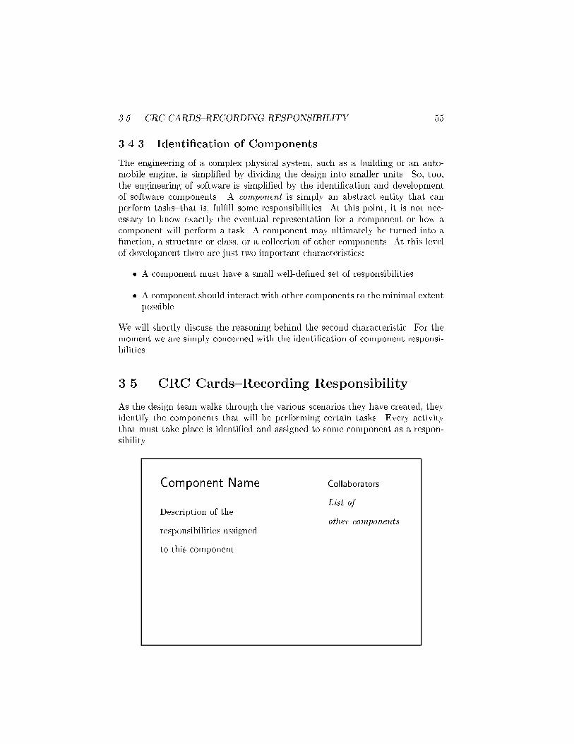
As the design team walks through the various scenarios they have created, theyidentify the components that will be performing certain tasks. Every activitythat must take place is identi�ed and assigned to some component as a respon-sibility.
Component Name Collaborators
List of
other componentsDescription of the
responsibilities assigned
to this component
56 CHAPTER 3. OBJECT-ORIENTED DESIGN
As part of this process, it is often useful to represent components using smallindex cards. Written on the face of the card is the name of the software compo-nent, the responsibilities of the component, and the names of other componentswith which the component must interact. Such cards are sometimes known asCRC (Component, Responsibility, Collaborator) cards, and are associated witheach software component. As responsibilities for the component are discovered,they are recorded on the face of the CRC card.
3.5.1 Give Components a Physical Representation
While working through scenarios, it is useful to assign CRC cards to di�erentmembers of the design team. The member holding the card representing a com-ponent records the responsibilities of the associated software component, andacts as the \surrogate" for the software during the scenario simulation. He orshe describes the activities of the software system, passing \control" to anothermember when the software system requires the services of another component.
An advantage of CRC cards is that they are widely available, inexpensive,and erasable. This encourages experimentation, since alternative designs can betried, explored, or abandoned with little investment. The physical separation ofthe cards encourages an intuitive understanding of the importance of the logicalseparation of the various components, helping to emphasize the cohesion andcoupling (which we will describe shortly). The constraints of an index card arealso a good measure of approximate complexity{a component that is expected toperform more tasks than can �t easily in this space is probably too complex, andthe team should �nd a simpler solution, perhaps by moving some responsibilitieselsewhere to divide a task between two or more new components.
3.5.2 The What/Who Cycle
As we noted at the beginning of this discussion, the identi�cation of componentstakes place during the process of imagining the execution of a working system.Often this proceeds as a cycle of what/who questions. First, the design teamidenti�es what activity needs to be performed next. This is immediately followedby answering the question of who performs the action. In this manner, designinga software system is much like organizing a collection of people, such as a club.Any activity that is to be performed must be assigned as a responsibility to somecomponent.
A popular bumper sticker states that phenomena can and will spontaneouslyoccur. (The bumper sticker uses a slightly shorter phrase.) We know, however,that in real life this is seldom true. If any action is to take place, there must bean agent assigned to perform it. Just as in the running of a club any action to beperformed must be assigned to some individual, in organizing an object-orientedprogram all actions must be the responsibility of some component. The secretto good object-oriented design is to �rst establish an agent for each action.

3.6. COMPONENTS AND BEHAVIOR 57
3.5.3 Documentation
At this point the development of documentation should begin. Two documentsshould be essential parts of any software system: the user manual and the systemdesign documentation. Work on both of these can commence even before the�rst line of code has been written.
The user manual describes the interaction with the system from the user'spoint of view; it is an excellent means of verifying that the development team'sconception of the application matches the client's. Since the decisions made increating the scenarios will closely match the decisions the user will be required tomake in the eventual application, the development of the user manual naturallydovetails with the process of walking through scenarios.
Before any actual code has been written, the mindset of the software teamis most similar to that of the eventual users. Thus, it is at this point that thedevelopers can most easily anticipate the sort of questions to which a noviceuser will need answers. A user manual is also an excellent tool to verify thatthe programming team is looking at the problem in the same way that the clientintended. A client seldom presents the programming team with a complete andformal speci�cation, and thus some reassurance and two-way communicationearly in the process, before actual programming has begun, can prevent majormisunderstandings.
The second essential document is the design documentation. The designdocumentation records the major decisions made during software design, andshould thus be produced when these decisions are fresh in the minds of thecreators, and not after the fact when many of the relevant details will have beenforgotten. It is often far easier to write a general global description of the softwaresystem early in the development. Too soon, the focus will move to the level ofindividual components or modules. While it is also important to document themodule level, too much concern with the details of each module will make itdi�cult for subsequent software maintainers to form an initial picture of thelarger structure.
CRC cards are one aspect of the design documentation, but many otherimportant decisions are not re ected in them. Arguments for and against anymajor design alternatives should be recorded, as well as factors that in uencedthe �nal decisions. A log or diary of the project schedule should be maintained.Both the user manual and the design documents are re�ned and evolve over timein exactly the same way the software is re�ned and evolves.
3.6 Components and Behavior
To return to the IIKH, the team decides that when the system begins, the userwill be presented with an attractive informative window (see Figure 3.1). Theresponsibility for displaying this window is assigned to a component called theGreeter. In some as yet unspeci�ed manner (perhaps by pull-down menus, button

58 CHAPTER 3. OBJECT-ORIENTED DESIGN
Greeter Collaborators
Database Manager
Plan ManagerDisplay Informative Initial Message
O�er User Choice of Options
Pass Control to either
Recipe Database Manager
Plan Manager for processing
Figure 3.3: { CRC card for the Greeter.
or key presses, or use of a pressure-sensitive screen), the user can select one ofseveral actions. Initially, the team identi�es just �ve actions:
1. Casually browse the database of existing recipes, but without reference toany particular meal plan.
2. Add a new recipe to the database.
3. Edit or annotate an existing recipe.
4. Review an existing plan for several meals.
5. Create a new plan of meals.
These activities seem to divide themselves naturally into two groups. The�rst three are associated with the recipe database; the latter two are associatedwith menu plans. As a result, the team next decides to create componentscorresponding to these two responsibilities. Continuing with the scenario, theteam elects to ignore the meal plan management for the moment and move onto re�ne the activities of the Recipe Database component. Figure 3.3 shows theinitial CRC card representation of the Greeter.
Broadly speaking, the responsibility of the recipe database component issimply to maintain a collection of recipes. We have already identi�ed threeelements of this task: The recipe component database must facilitate browsingthe library of existing recipes, editing the recipes, and including new recipes inthe database.

3.6. COMPONENTS AND BEHAVIOR 59
3.6.1 Postponing Decisions
There are a number of decisions that must eventually be made concerning howbest to let the user browse the database. For example, should the user �rstbe presented with a list of categories, such as \soups," \salads," \main meals,"and \desserts"? Alternatively, should the user be able to describe keywords tonarrow a search, perhaps by providing a list of ingredients, and then see all therecipes that contain those items (\Almonds, Strawberries, Cheese"), or a listof previously inserted keywords (\Bob's favorite cake")? Should scroll bars beused or simulated thumb holes in a virtual book? These are fun to think about,but the important point is that such decisions do not need to be made at thispoint (see Section 3.6.2, \Preparing for Change"). Since they a�ect only a singlecomponent, and do not a�ect the functioning of any other system, all that isnecessary to continue the scenario is to assert that by some means the user canselect a speci�c recipe.
3.6.2 Preparing for Change
It has been said that all that is constant in life is the inevitability of uncertaintyand change. The same is true of software. No matter how carefully one triesto develop the initial speci�cation and design of a software system, it is almostcertain that changes in the user's needs or requirements will, sometime duringthe life of the system, force changes to be made in the software. Programmersand software designers need to anticipate this and plan accordingly.
� The primary objective is that changes should a�ect as few componentsas possible. Even major changes in the appearance or functioning of anapplication should be possible with alterations to only one or two sectionsof code.
� Try to predict the most likely sources of change and isolate the e�ectsof such changes to as few software components as possible. The mostlikely sources of change are interfaces, communication formats, and outputformats.
� Try to isolate and reduce the dependency of software on hardware. Forexample, the interface for recipe browsing in our application may dependin part on the hardware on which the system is running. Future releasesmay be ported to di�erent platforms. A good design will anticipate thischange.
� Reducing coupling between software components will reduce the depen-dence of one upon another, and increase the likelihood that one can bechanged with minimal e�ect on the other.
� In the design documentation maintain careful records of the design processand the discussions surrounding all major decisions. It is almost certain

60 CHAPTER 3. OBJECT-ORIENTED DESIGN
that the individuals responsible for maintaining the software and designingfuture releases will be at least partially di�erent from the team producingthe initial release. The design documentation will allow future teams toknow the important factors behind a decision and help them avoid spendingtime discussing issues that have already been resolved.
3.6.3 Continuing the Scenario
Each recipe will be identi�ed with a speci�c recipe component. Once a recipe isselected, control is passed to the associated recipe object. A recipe must containcertain information. Basically, it consists of a list of ingredients and the stepsneeded to transform the ingredients into the �nal product. In our scenario, therecipe component must also perform other activities. For example, it will displaythe recipe interactively on the terminal screen. The user may be given the abilityto annotate or change either the list of ingredients or the instruction portion.Alternatively, the user may request a printed copy of the recipe. All of theseactions are the responsibility of the Recipe component. (For the moment, we willcontinue to describe the Recipe in singular form. During design we can think ofthis as a prototypical recipe that stands in place of a multitude of actual recipes.We will later return to a discussion of singular versus multiple components.)
Having outlined the actions that must take place to permit the user to browsethe database, we return to the recipe database manager and pretend the userhas indicated a desire to add a new recipe. The database manager somehowdecides in which category to place the new recipe (again, the details of how thisis done are unimportant for our development at this point), requests the name ofthe new recipe, and then creates a new recipe component, permitting the user toedit this new blank entry. Thus, the responsibilities of performing this new taskare a subset of those we already identi�ed in permitting users to edit existingrecipes.
Having explored the browsing and creation of new recipes, we return to theGreeter and investigate the development of daily menu plans, which is the PlanManager's task. In some way (again, the details are unimportant here) theuser can save existing plans. Thus, the Plan Manager can either be startedby retrieving an already developed plan or by creating a new plan. In thelatter case, the user is prompted for a list of dates for the plan. Each date isassociated with a separateDate component. The user can select a speci�c date forfurther investigation, in which case control is passed to the corresponding Datecomponent. Another activity of the Plan Manager is printing out the recipes forthe planning period. Finally, the user can instruct the Plan Manager to producea grocery list for the period.
The Date component maintains a collection of meals as well as any other an-notations provided by the user (birthday celebrations, anniversaries, reminders,and so on). It prints information on the display concerning the speci�ed date.By some means (again unspeci�ed), the user can indicate a desire to print allthe information concerning a speci�c date or choose to explore in more detail a
3.6. COMPONENTS AND BEHAVIOR 61
��
���
���
��
��
��
��
��
����
��
Plan Manager
Date
Greeter
Recipe Database
Meal Recipe
��
@@
HHH
HHHH
���
QQQQQ
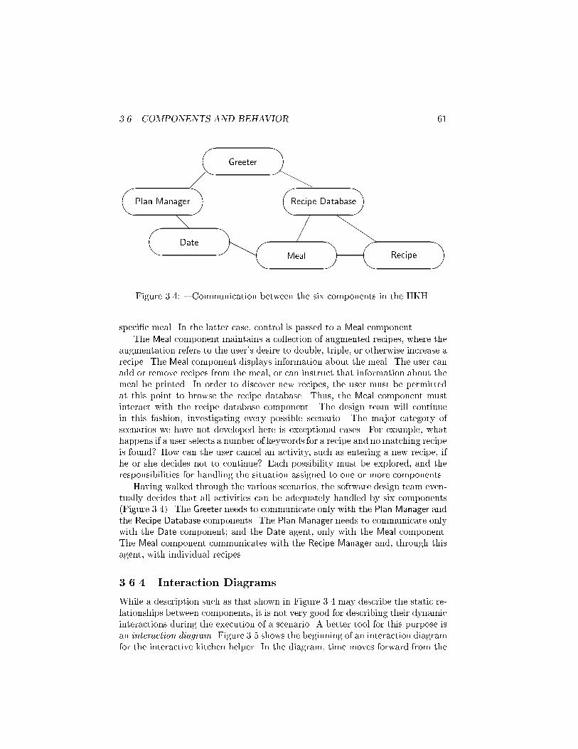
Figure 3.4: { Communication between the six components in the IIKH.
speci�c meal. In the latter case, control is passed to a Meal component.
The Meal component maintains a collection of augmented recipes, where theaugmentation refers to the user's desire to double, triple, or otherwise increase arecipe. The Meal component displays information about the meal. The user canadd or remove recipes from the meal, or can instruct that information about themeal be printed. In order to discover new recipes, the user must be permittedat this point to browse the recipe database. Thus, the Meal component mustinteract with the recipe database component. The design team will continuein this fashion, investigating every possible scenario. The major category ofscenarios we have not developed here is exceptional cases. For example, whathappens if a user selects a number of keywords for a recipe and no matching recipeis found? How can the user cancel an activity, such as entering a new recipe, ifhe or she decides not to continue? Each possibility must be explored, and theresponsibilities for handling the situation assigned to one or more components.
Having walked through the various scenarios, the software design team even-tually decides that all activities can be adequately handled by six components(Figure 3.4). The Greeter needs to communicate only with the Plan Manager andthe Recipe Database components. The Plan Manager needs to communicate onlywith the Date component; and the Date agent, only with the Meal component.The Meal component communicates with the Recipe Manager and, through thisagent, with individual recipes.
3.6.4 Interaction Diagrams
While a description such as that shown in Figure 3.4 may describe the static re-lationships between components, it is not very good for describing their dynamicinteractions during the execution of a scenario. A better tool for this purpose isan interaction diagram. Figure 3.5 shows the beginning of an interaction diagramfor the interactive kitchen helper. In the diagram, time moves forward from the

62 CHAPTER 3. OBJECT-ORIENTED DESIGN
Greeter Database Recipe Planner Comment
Message browse()-
Message display()-
Return from display()�
Return from browse()�
Message makePlan()-
Figure 3.5: { An Example interaction diagram.
top to the bottom. Each component is represented by a labeled vertical line. Acomponent sending a message to another component is represented by a hori-zontal arrow from one line to another. Similarly, a component returning controland perhaps a result value back to the caller is represented by an arrow. (Someauthors use two di�erent arrow forms, such as a solid line to represent messagepassing and a dashed line to represent returning control.) The commentary onthe right side of the �gure explains more fully the interaction taking place.
With a time axis, the interaction diagram is able to describe better the se-quencing of events during a scenario. For this reason, interaction diagrams canbe a useful documentation tool for complex software systems.
3.7 Software Components
In this section we will explore a software component in more detail. As is trueof all but the most trivial ideas, there are many aspects to this seemingly simpleconcept.
3.7.1 Behavior and State
We have already seen how components are characterized by their behavior, thatis, by what they can do. But components may also hold certain information.Let us take as our prototypical component a Recipe structure from the IIKH.One way to view such a component is as a pair consisting of behavior and state.
� The behavior of a component is the set of actions it can perform. Thecomplete description of all the behavior for a component is sometimes

3.7. SOFTWARE COMPONENTS 63
called the protocol. For the Recipe component this includes activities suchas editing the preparation instructions, displaying the recipe on a terminalscreen, or printing a copy of the recipe.
� The state of a component represents all the information held within itat a given point of time. For our Recipe component the state includes theingredients and preparation instructions. Notice that the state is not staticand can change over time. For example, by editing a recipe (a behavior)the user can make changes to the preparation instructions (part of thestate).
It is not necessary that all components maintain state information. For ex-ample, it is possible that the Greeter component will not have any state sinceit does not need to remember any information during the course of execution.However, most components will consist of a combination of behavior and state.
3.7.2 Instances and Classes
The separation of state and behavior permits us to clarify a point we avoidedin our earlier discussion. Note that in the real application there will probablybe many di�erent recipes. However, all of these recipes will perform in the samemanner. That is, the behavior of each recipe is the same; it is only the state{the individual lists of ingredients and instructions for preparation{that di�ersbetween individual recipes. In the early stages of development our interest is incharacterizing the behavior common to all recipes; the details particular to anyone recipe are unimportant.
The term class is used to describe a set of objects with similar behavior. Wewill see in later chapters that a class is also used as a syntactic mechanism inalmost all object-oriented languages. An individual representative of a class isknown as an instance. Note that behavior is associated with a class, not with anindividual. That is, all instances of a class will respond to the same instructionsand perform in a similar manner. On the other hand, state is a property of anindividual. We see this in the various instances of the class Recipe. They can allperform the same actions (editing, displaying, printing) but use di�erent datavalues.
3.7.3 Coupling and Cohesion
Two important concepts in the design of software components are coupling andcohesion. Cohesion is the degree to which the responsibilities of a single com-ponent form a meaningful unit. High cohesion is achieved by associating in asingle component tasks that are related in some manner. Probably the mostfrequent way in which tasks are related is through the necessity to access a com-mon data value. This is the overriding theme that joins, for example, the variousresponsibilities of the Recipe component.

64 CHAPTER 3. OBJECT-ORIENTED DESIGN
Coupling, on the other hand, describes the relationship between softwarecomponents. In general, it is desirable to reduce the amount of coupling asmuch as possible, since connections between software components inhibit ease ofdevelopment, modi�cation, or reuse.
In particular, coupling is increased when one software component must accessdata values{the state{held by another component. Such situations should almostalways be avoided in favor of moving a task into the list of responsibilities of thecomponent that holds the necessary data. For example, one might conceivably�rst assign responsibility for editing a recipe to the Recipe Database component,since it is while performing tasks associated with this component that the need toedit a recipe �rst occurs. But if we did so, the Recipe Database agent would needthe ability to directly manipulate the state (the internal data values representingthe list of ingredients and the preparation instructions) of an individual recipe.It is better to avoid this tight connection by moving the responsibility for editingto the recipe itself.
3.7.4 Interface and Implementation{Parnas's Principles
The emphasis on characterizing a software component by its behavior has oneextremely important consequence. It is possible for one programmer to knowhow to use a component developed by another programmer, without needing toknow how the component is implemented. For example, suppose each of the sixcomponents in the IIKH is assigned to a di�erent programmer. The programmerdeveloping the Meal component needs to allow the IIKH user to browse thedatabase of recipes and select a single recipe for inclusion in the meal. To dothis, the Meal component can simply invoke the browse behavior associated withthe Recipe Database component, which is de�ned to return an individual Recipe.This description is valid regardless of the particular implementation used by theRecipe Database component to perform the actual browsing action.
The purposeful omission of implementation details behind a simple interfaceis known as information hiding. We say the component encapsulates the behav-ior, showing only how the component can be used, not the detailed actions itperforms. This naturally leads to two di�erent views of a software system. Theinterface view is the face seen by other programmers. It describes what a soft-ware component can perform. The implementation view is the face seen by theprogrammer working on a particular component. It describes how a componentgoes about completing a task.
The separation of interface and implementation is perhaps the most impor-tant concept in software engineering. Yet it is di�cult for students to understand,or to motivate. Information hiding is largely meaningful only in the context ofmultiperson programming projects. In such e�orts, the limiting factor is oftennot the amount of coding involved, but the amount of communication requiredbetween the various programmers and between their respective software systems.As we will describe shortly, software components are often developed in parallelby di�erent programmers, and in isolation from each other.

3.8. FORMALIZE THE INTERFACE 65
There is also an increasing emphasis on the reuse of general-purpose softwarecomponents in multiple projects. For this to be successful, there must be minimaland well-understood interconnections between the various portions of the system.As we noted in the previous chapter, these ideas were captured by computerscientist David Parnas in a pair of rules, known as Parnas's principles:
� The developer of a software component must provide the intended user withall the information needed to make e�ective use of the services providedby the component, and should provide no other information.
� The developer of a software component must be provided with all theinformation necessary to carry out the given responsibilities assigned tothe component, and should be provided with no other information.
A consequence of the separation of interface from implementation is that aprogrammer can experiment with several di�erent implementations of the samestructure without a�ecting other software components.
3.8 Formalize the Interface
We continue with the description of the IIKH development. In the next severalsteps the descriptions of the components will be re�ned. The �rst step in thisprocess is to formalize the patterns and channels of communication.
A decision should be made as to the general structure that will be used to im-plement each component. A component with only one behavior and no internalstate may be made into a function{for example, a component that simply takesa string of text and translates all capital letters to lowercase. Components withmany tasks are probably more easily implemented as classes. Names are given toeach of the responsibilities identi�ed on the CRC card for each component, andthese will eventually be mapped onto method names. Along with the names, thetypes of any arguments to be passed to the function are identi�ed. Next, theinformation maintained within the component itself should be described. All in-formation must be accounted for. If a component requires some data to performa speci�c task, the source of the data, either through argument or global value,or maintained internally by the component, must be clearly identi�ed.
3.8.1 Coming up with Names
Careful thought should be given to the names associated with various activities.Shakespeare said that a name change does not alter the object being described,but certainly not all names will conjure up the same mental images in the listener.As government bureaucrats have long known, obscure and idiomatic names canmake even the simplest operation sound intimidating. The selection of usefulnames is extremely important, as names create the vocabulary with which theeventual design will be formulated. Names should be internally consistent, mean-ingful, preferably short, and evocative in the context of the problem. Often a

66 CHAPTER 3. OBJECT-ORIENTED DESIGN
considerable amount of time is spent �nding just the right set of terms to de-scribe the tasks performed and the objects manipulated. Far from being a barrenand useless exercise, proper naming early in the design process greatly simpli�esand facilitates later steps.
The following general guidelines have been suggested:
� Use pronounceable names. As a rule of thumb, if you cannot read a nameout loud, it is not a good one.
� Use capitalization (or underscores) to mark the beginning of a new wordwithin a name, such as \CardReader" or \Card reader," rather than theless readable \cardreader."
� Examine abbreviations carefully. An abbreviation that is clear to one per-son may be confusing to the next. Is a \TermProcess" a terminal process,something that terminates processes, or a process associated with a termi-nal?
� Avoid names with several interpretations. Does the empty function tellwhether something is empty, or empty the values from the object?
� Avoid digits within a name. They are easy to misread as letters (0 as O,1 as l, 2 as Z, 5 as S).
� Name functions and variables that yield Boolean values so they describeclearly the interpretation of a true or false value. For example, \Printer-IsReady" clearly indicates that a true value means the printer is working,whereas \PrinterStatus" is much less precise.
� Take extra care in the selection of names for operations that are costly andinfrequently used. By doing so, errors caused by using the wrong functioncan be avoided.
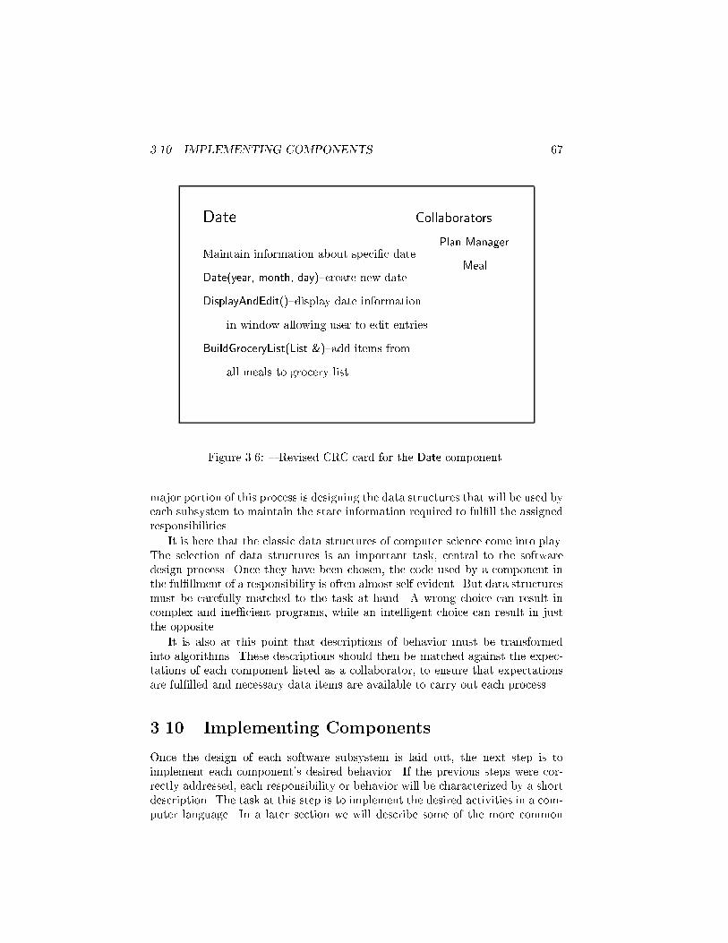
Once names have been developed for each activity, the CRC cards for eachcomponent are redrawn, with the name and formal arguments of the functionused to elicit each behavior identi�ed. An example of a CRC card for the Dateis shown in Figure 3.6. What is not yet speci�ed is how each component willperform the associated tasks.
Once more, scenarios or role playing should be carried out at a more de-tailed level to ensure that all activities are accounted for, and that all necessaryinformation is maintained and made available to the responsible components.
3.9 Designing the Representation
At this point, if not before, the design team can be divided into groups, eachresponsible for one or more software components. The task now is to transformthe description of a component into a software system implementation. The
3.10. IMPLEMENTING COMPONENTS 67
Date Collaborators
Plan Manager
MealMaintain information about speci�c date
Date(year, month, day){create new date
DisplayAndEdit(){display date information
in window allowing user to edit entries
BuildGroceryList(List &){add items from
all meals to grocery list
Figure 3.6: { Revised CRC card for the Date component.
major portion of this process is designing the data structures that will be used byeach subsystem to maintain the state information required to ful�ll the assignedresponsibilities.
It is here that the classic data structures of computer science come into play.The selection of data structures is an important task, central to the softwaredesign process. Once they have been chosen, the code used by a component inthe ful�llment of a responsibility is often almost self-evident. But data structuresmust be carefully matched to the task at hand. A wrong choice can result incomplex and ine�cient programs, while an intelligent choice can result in justthe opposite.
It is also at this point that descriptions of behavior must be transformedinto algorithms. These descriptions should then be matched against the expec-tations of each component listed as a collaborator, to ensure that expectationsare ful�lled and necessary data items are available to carry out each process.
3.10 Implementing Components
Once the design of each software subsystem is laid out, the next step is toimplement each component's desired behavior. If the previous steps were cor-rectly addressed, each responsibility or behavior will be characterized by a shortdescription. The task at this step is to implement the desired activities in a com-puter language. In a later section we will describe some of the more common
68 CHAPTER 3. OBJECT-ORIENTED DESIGN
heuristics used in this process.
If they were not determined earlier (say, as part of the speci�cation of thesystem), then decisions can now be made on issues that are entirely self-containedwithin a single component. A decision we saw in our example problem was howbest to let the user browse the database of recipes.
As multiperson programming projects become the norm, it becomes increas-ingly rare that any one programmer will work on all aspects of a system. Moreoften, the skills a programmer will need to master are understanding how onesection of code �ts into a larger framework and working well with other membersof a team.
Often, in the implementation of one component it will become clear thatcertain information or actions might be assigned to yet another component thatwill act \behind the scene," with little or no visibility to users of the softwareabstraction. Such components are sometimes known as facilitators. We will seeexamples of facilitators in some of the later case studies.
An important part of analysis and coding at this point is characterizing anddocumenting the necessary preconditions a software component requires to com-plete a task, and verifying that the software component will perform correctlywhen presented with legal input values.
3.11 Integration of Components
Once software subsystems have been individually designed and tested, they canbe integrated into the �nal product. This is often not a single step, but part ofa larger process. Starting from a simple base, elements are slowly added to thesystem and tested, using stubs{simple dummy routines with no behavior or withvery limited behavior{for the as yet unimplemented parts.
For example, in the development of the IIKH, it would be reasonable to startintegration with the Greeter component. To test the Greeter in isolation, stubs arewritten for the Recipe Databasemanager and the dailyMeal Planmanager. Thesestubs need not do any more than print an informative message and return. Withthese, the component development team can test various aspects of the Greetersystem (for example, that button presses elicit the correct response). Testing ofan individual component is often referred to as unit testing.
Next, one or the other of the stubs can be replaced by more complete code.For example, the team might decide to replace the stub for the Recipe Databasecomponent with the actual system, maintaining the stub for the other portion.Further testing can be performed until it appears that the system is working asdesired. (This is sometimes referred to as integration testing.)
The application is �nally complete when all stubs have been replaced withworking components. The ability to test components in isolation is greatly facili-tated by the conscious design goal of reducing connections between components,since this reduces the need for extensive stubbing.
During integration it is not uncommon for an error to be manifested in one

3.12. MAINTENANCE AND EVOLUTION 69
software system, and yet to be caused by a coding mistake in another system.Thus, testing during integration can involve the discovery of errors, which thenresults in changes to some of the components. Following these changes the com-ponents should be once again tested in isolation before an attempt to reintegratethe software, once more, into the larger system. Reexecuting previously devel-oped test cases following a change to a software component is sometimes referredto as regression testing.
3.12 Maintenance and Evolution
It is tempting to think that once a working version of an application has beendelivered the task of the software development team is �nished. Unfortunately,that is almost never true. The term software maintenance describes activitiessubsequent to the delivery of the initial working version of a software system. Awide variety of activities fall into this category.
� Errors, or bugs, can be discovered in the delivered product. These mustbe corrected, either in updates or corrections to existing releases or insubsequent releases.
� Requirements may change, perhaps as a result of government regulationsor standardization among similar products.
� Hardware may change. For example, the system may be moved to di�erentplatforms, or input devices, such as a pen-based system or a pressure-sensitive touch screen, may become available. Output technology maychange{for example, from a text-based system to a graphical window-basedarrangement.
� User expectations may change. Users may expect greater functionality,lower cost, and easier use. This can occur as a result of competition withsimilar products.
� Better documentation may be requested by users.
A good design recognizes the inevitability of changes and plans an accommo-dation for them from the very beginning.
Chapter Summary
In this chapter we have presented a very abbreviated introduction to the basicideas of object-oriented modeling and design. References in the following sectioncan be consulted for more detailed discussion of this topic.
Object-oriented design di�ers from conventional software design in that thedriving force is the assignment of responsibilities to di�erent software compo-nents. No action will take place without an agent to perform the action, and
70 CHAPTER 3. OBJECT-ORIENTED DESIGN
hence every action must be assigned to some member of the object community.Conversely, the behavior of the members of the community taken together mustbe su�cient to achieve the desired goal.
The emphasis on behavior is a hall-mark of object-oriented programming.Behavior can be identi�ed in even the most rudimentary descriptions of a system,long before any other aspect can be clearly discerned. By constantly beingdriven by behavior, responsibility driven design moves smoothly from problemdescription to software architecture to code development to �nished application.
Further Reading
Responsibility-driven design was developed and �rst described by Rebecca Wirfs-Brock [Wirfs-Brock 1989b, Wirfs-Brock 1990]. There are many other object-oriented design techniques, such as that of Jacobson [Jacobson 1994] or Rum-baugh [Rumbaugh 1991], but I like responsibility-driven design because it isamong the simplest to explain, and is therefore a good introduction to object-oriented design and modeling.
Much of the most recent work in the �eld of object-oriented design has cen-tered on UML, the Uni�ed Modeling Language. I are not going to discuss UMLin detail in this book, although I do use some of their notation in describingclass diagrams. A good introduction to UML is [Booch 1999]. A slightly simplerexplanation is found in [Alhir 1998].
Other good books on object-oriented design include [Rumbaugh 1991] and[Henderson-Sellers 1992].
CRC cards were developed by Beck [Beck 1989]. A more in-depth book-length treatment of the idea is [Bellin 1997].
Parnas's principles were �rst presented in [Parnas 1972].
The guidelines on names presented in Section 3.8.1 are from [Keller 1990].The Shakespeare reference in that same section is to Romeo and Juliet, Act II,Scene 2:
What's in a name?That which we call a rose,by any other name would smell as sweet;So Romeo would, were he not Romeo call'd,retain that dear perfection which he owes without that title.
Self Study Questions
1. What are the key features of responsibility-driven design?
2. What are some key di�erences between programming in-the-small and pro-gramming in-the-large?

EXERCISES 71
3. Why can a design technique based on behavior be applied more easily topoorly-de�ned problems than can, say, a design approach based on datastructures?
4. What is a scenario?
5. What are the basic elements of a component?
6. What is a CRC card? What do the letters stand for?
7. What is the what/who cycle?
8. Why should a user manual be developed before coding begins?
9. What are the major sources of change that can be expected during thelifetime of most long-lived software applications?
10. What information is conveyed by an interaction diagram?
11. What are Parnas's principles?
12. Why is the selection of good names an important aspect of a successfulsoftware design e�ort? What are some guidelines for choosing names?
13. What is integration testing?
14. What is software maintenance?
Exercises
1. Describe the responsibilities of an organization that includes at least sixtypes of members. Examples of such organizations are a school (students,teachers, principal, janitor), a business (secretary, president, worker), and aclub (president, vice-president, member). For each member type, describethe responsibilities and the collaborators.
2. Create a scenario for the organization you described in Exercise 1 using aninteraction diagram.
3. For a common game such as solitaire or twenty-one, describe a softwaresystem that will interact with the user as an opposing player. Examplecomponents include the deck and the discard pile.
4. Describe the software system to control an ATM (Automated Teller Ma-chine). Give interaction diagrams for various scenarios that describe themost common uses of the machine.
Related Documents