AGARD : 9 5 ti a 8 ADVISORY GROUP FOR AEROSPACE RESEARCH & DEVELOPMENT 7 RUE ANCELLE, 92200 NEUILLY-SUR-SEINE, FRANCE Space Systems as Contributors to the NATO Defence Mission (les Systbes spatiaux contribuant i?i la strat6gie de ddfense de YOTAN) Papers presented at the Mission Systems Panel Sth Symposium held in Cannes, France, 3-6 June 1996. Publlshed June 1997 cww

Welcome message from author
This document is posted to help you gain knowledge. Please leave a comment to let me know what you think about it! Share it to your friends and learn new things together.
Transcript
AGARD : 9 5 t i a 8 ADVISORY GROUP FOR AEROSPACE RESEARCH & DEVELOPMENT
7 RUE ANCELLE, 92200 NEUILLY-SUR-SEINE, FRANCE
Space Systems as Contributors to the NATO Defence Mission (les Systbes spatiaux contribuant i?i la strat6gie de ddfense de YOTAN)
Papers presented at the Mission Systems Panel Sth Symposium held in Cannes, France, 3-6 June 1996.
Publlshed June 1997
cww

AGARD-CP-580
ADVISORYGROUPFORAEROSPACERESEARCH &DEVELOPMENT
7 RUE ANCELLE, 92200 NEUILLY-SUR-SEINE, FRANCE
AGARD CONFERENCE PROCEEDINGS 580
Space Systems as Contributors to the NATO Defence Mission (les Systkmes spatiaux contribuant B la strategic de defense de 1'OTAN)
Papers presented at the Mission Systems Panel 5th Symposium held in Cannes, France, 3-6 June 1996.
North Atlantic Treaty Organization Organisation du Traite de I'Atlantique Nord i
I I
The Mission of AGARD
According to its Charter, the mission of AGARD is to bring together the leading personalities of the NATO nations in the fields of science and technology relating to aerospace for the following purposes:
- Recommending effective ways for the member nations to use their research and development capabilities for the common benefit of the NATO community;
- Providing scientific and technical advice and assistance to the Military Committee in the field of aerospace research and development (with particular regard to its military application);
- Continuously stimulating advances in the aerospace sciences relevant to strengthening the common defence posture;
- Improving the co-operation among member nations in aerospace research and development;
- Exchange of scientific and technical information;
- Providing assistance to member nations for the purpose of increasing their scientific and technical potential;
- Rendering scientific and technical assistance, as requested, to other NATO bodies and to member nations in connection with research and development problems in the aerospace field.
The highest authority within AGARD is the National Delegates Board consisting of officially appointed senior representatives from each member nation. The mission of AGARD is carried out through the Panels which are composed of experts appointed by the National Delegates, the Consultant and Exchange Programme and the Aerospace Applications Studies Programme. The results of AGARD work are reported to the member nations and the NATO Authorities through the AGARD series of publications of which this is one.
Participation in AGARD activities is by invitation only and is normally limited to citizens of the NATO nations.
The content of this publication has been reproduced directly from material supplied by AGARD or the authors.
Published June 1997
Copyright 0 AGARD 1997 All Rights Reserved
ISBN 92-836-0041 -X
Printed by Canada Communication Group Inc. ( A St. Joseph Corporation Company)
45 Sacri-Ceur Blvd., Hull (Quibec), Canada KIA OS7
ii
Les systitmes spatiaux en tant que contribution B la mission de defense de I’OTAN
(AGARD CP-580)
I
Les systkmes spatiaux peuvent fournir un soutien capital au dispositif OTAN de commandement, contr8le et information.
Les communications par satellite constituent d6jB un Clement non nCgligeable de l’architecture de tels systkmes, mais les nouveaux moyens spatiaux en developpement en dehors de 1’OTAN et dans le secteur commercial offrent des avantages aussi bien B 1’OTAN qu’h ses adversaires potentiels. Bien que l’utilisateur militaire soit conscient des avantages offerts par d’autres systkmes spatiaux plus exotiques, ainsi que par les satellites tactiques TACSATS B dimensions rkduites et B moindre coQt, il doit tenir compte des questions soulevCes par la mise en oeuvre de ces moyens.
L’objectif principal de ce symposium a CtC de dkmontrer l’utilite et la faisabilitk pour 1’OTAN de disposer d’une large gamme d’applications spatiales, en facilitant des Cchanges rkciproques entre les militaires et les scientifiques de la communaute de defense. Les communications presentees ont couvert un Cventail considkrable de possibilitCs techniques, mais une contribution plus importante de la part de la communautk militaire aurait permis de mieux Cquilibrer le programme.
Le symposium a debut6 par des prksentations sur les perspectives militaires qui ont donne l’orientation de la seance pour les diffkrentes sessions. Les divers aspects des possibilitks techniques ont pu Ctre present& et particulikrement:
* les systkmes civilskommerciaux; les communications; la surveillance;
* la mCtCorologie; * le fusionnement des donnCes; * l’extraction des informations.
Le symposium s’est termink par une table ronde B l’occasion de laquelle les participants ont souligne l’importance du r81e que peuvent jouer les systkmes spatiaux pour 1’OTAN. 11s ont aussi propose la crCation d’un bureau des programmes spatiaux de 1’OTAN qui aurait pour mandat d’ttablir une politique concernant:
0 l’utilisation des systkmes spatiaux; o les applications de combat des systkmes spatiaux; o la coordination entre la politique adoptee en matikre de systkmes spatiaux et les autres ClCments
Globalement, les communications pr6sentCes ont couvert en profondeur un large domaine. Elles ont donnC lieu B des discussions animCes et ont permis d’identifier certaines preoccupations actuelles. Le comitC du programme estime que le symposium a atteint son objectif. De plus, il a fourni des recommandations concernant une dCmarche initiale possible pour 1’ OTAN, ce qui lui permettrait d’etendre son champ d’utilisation et d’klargir ses connaissances actuelles en matikre de systkmes spatiaux.
opCrationnels (et d’entrainement) des forces de 1’OTAN.
C D Hall President du comit6 du programme
iv
Space Systems as Contributors to the NATO Defence Mission
(AGARD CP-580)
Executive Summary
Space can provide vital support to the NATO Command, Control and Information System.
Satellite communications already form a significant component of such systems, but the burgeoning space capabilities now being developed outside NATO and in the commercial sector offer benefits to potential adversaries as well as NATO. While the military user is already aware of the benefits of other, exotic, space systems and of the potential benefit from smaller, cheaper tactical satellites (Tacsats), he needs to take account of the issues raised by these capabilities.
The overall objective of this symposium was to demonstrate the utility and feasibility for NATO of a wider range of space applications, and provide a cross fertilisation between military minds and the technical/scientific minds that work in the defence community. The papers presented addressed a wide range of technical capabilities, although a larger contribution from the military side of the defence community would have improved the balance of the proceedings.
The symposium was structured to open with presentations of military perspectives providing focus to subsequent sessions, which addressed various aspects of technical capability ranging through the following:
0 Civilkommercial systems; 0 Communications; 0 Surveillance; 0 Meteorology; 0 Data fusion; 0 Information extraction.
The symposium concluded with a panel and audience discussion, during which participants reinforced the importance of the role that space can play for NATO and proposed that NATO should form a “Space Programme Office” to establish a policy covering:
0 space systems utilisation; 0 space systems applications to warfighting; 0 co-ordination of space systems policy with other warfighting (and training) elements of NATO
Overall, the papers presented covered a wide area in considerable depth, stimulating some animated discussion and identifying concerns. The programme committee feels that the symposium achieved its objective and, in addition, provided recommendations of some initial steps for NATO to extend its utilisation and awareness of space systems beyond the present status.
forces.
C D Hall Programme Committee Chairman
N
Contents
Executive Summary
S ynthbe
Theme/Th&me
Panel Officers and Programme Committee
Technical Evaluation Report by B.F. Plummer
Opening Address by IGA J.-P. Marec
Keynote Address by IGA D. Estournet
Page
iii
iv
viii
ix
Reference
T
0
K
SESSION I: INVITED PAPERS Chairman: Mr. D. Hall (UK)
The Evolving NATO Satellite Experience by P.A. Kelly
Possibilities and Limitations of Spaceborne SAR with Respect to Military Reconnaissance by W. Keydel
Potential Use of Commercial Satellite Systems for Military Applications by N. Motowylak
SESSION 11: MILITARY APPLICATIONS OF CIVIL SYSTEMS Chairman: Mr. A. Salomon (FR)
Concept de Satellites Civils pour des Applications de Communications Militaires by B. Troy
RADARSAT: A Military Opportunity by D.J. Hisdal, J. Hornsby, G. Staples and R. Cox
NATO Naval Exercises as Observed from Civilian Radar Satellites by T. Wahl and A. Skoelv
Radar Backscatter Statistics from the Sea Surface: Implications of SIR-CK-SAR Observations for Maritime Surveillance
by J.T. Macklin, N.R. Stapleton, N.A. Robertson and R. Ringrose
1
2
3"
4"
5*
6
7
* Published in Classified Supplement
V
I
SESSION IIIA: COMMUNICATIONS (SYSTEMS) Chairman: Dr. H. Rugge (US)
Possible Features of NATO Communications Satellite Gap Filler by P. Ricci and A. Franzosi
Paper 9 withdrawn
A Long Term Perspective on MILSATCOMS Beyond the Year 2015 by A.C. Stanniland and S.J.M. Prodger
Presentation of the Future Generation of Military Satellite Communications Systems by E. Boudjema, P. Gaudemet and J.F. Primard
A Timely Review of EHF Benefits in a MILSATCOM Environment by B.S. Badial and G.J. Robertson
SESSION IIIB: COMMUNICATIONS (TECHNOLOGY)
RCsultats ExpCrimentaux d'Antibrouillage d'une Antenne EmbarquCe de TClCcommunication par Satellite
by P. Tutard, J.P. Poux and F. Croq
Technologies NumCriques pour une Charge Utile Anti-BrouillCe de TClCcommunications par Satellites
by M. Armand, Ph. Elleaume, B. Muller, J.P. Poux, J.F. Primard and T. Quignon
SESSION IVA: SURVEILLANCE (RECONNAISSANCE) Chairman: Mr. J-B. Senneville (FR)
Spaceborne Theater Survey System by G. Cerutti-Maori
Tactical Reconnaissance by a Constellation of Small Satellites by C. Dionisio and G. Perrotta
SESSION IVB: SURVEILLANCE (METEOROLOGY)
Interpretation of Passive Microwave Radiances for Tactical Applications: Current and Future Capabilities of the Defense Meteorological Satellite Program (DMSP)
by D.J. Boucher, B.H. Thomas and C. Holliday
Small Meteorological Satellites for NATO Military Operations by D.P. Duclos, R.G. Feddes and G.E. Gurevich
SESSION IVC: SURVEILLANCE (EARLY WARNING)
Systemes Spatiaux d'Alerte PrCcoce et de DCfense Anti-Missile de ThCQtre by H. Gilibert, E. Bruguet, P. Deniau, C. Hug and C. Chicher
Satellite-Based TBM Early Warning: Cueing of Radar Systems by K-H. Keil, S. Craubner, E. Schulz-Lupertz and K-L. Bitzer
8
10"
11"
12"
13
14
17
18
19t
20"
* Published in Classified Supplement t Not available at time of printing
vi
Electro-Optical Sensor Simulation for Theater Missile Warning by D.G. Lawrie, S.L. Kafesjian, J.N. Hamilton, E.J. Casey, I.S. Robinson and M.M. Jacobs
SESSION V: INFORMATION EXTRACTION Chairman: Ing P. Ph. van den Broek (NE)
Le Renseignement d’Origine Image dans un Contexte Multi-senseurs (Image Intelligence in a Multisensor Context)
by J-M. Nasr
Paper 23 withdrawn
Integrated Air Deployed Strike Surveillance (IADSS) by P. O’Connell and D.J. Bielecki
Application-Specific Bandwidth Compression for Dissemination of Image Data by S.B. Danahy, H.S. Hou, A. Habibi and E.M. Bassett, I11
21
22”
24
25
SESSION VI: VEHICLE MANAGEMENT Chairman: Dr. T. Cunningham (US)
Results of Global Positioning System Guidance Package (GGP) Technology Demonstration 26 by B. Kaspar, J. Aein, A. Killen and N. Dahlen
Paper 27 withdrawn
Future Space Transportation Systems and Their Potential Contribution to the NATO Mission
by C.L. Whitehair and M.G. Wolfe
Multi-Launch Vehicle Integration Issues for Military Satellites by J.A. Yahner and G.A. Deabler
SESSION VII: FUTURE SYSTEMS AND PANEL DISCUSSION Chaiman: Mr. D. Hall (UK)
Strawman Concept and Panel Discussion by C.D. Hall
* Published in Classified Supplement t Not available at time of printing
vii
28
29
30
Theme
The fine technical capability of current military space assets has led to a keen appreciation of their military value and a growing demand for the services that they can provide. However, the large cost of providing this capability to every potential user is a driver towards effective and affordable, rather than ultimate, systems. Working Group (WG 16) of the disbanded Avionics Panel has recently addressed the military capabilities that can be provided by smaller, cheaper satellites - Tacsats. This Symposium covers different ground.
Therefore, the overall objective of this Symposium is to demonstrate the utility and feasibility of wider range space applications of NATO. The Symposium is structured with the following major areas, and aims to show the derivation of system solutions to mission requirements:
possible future requirements for NATO space applications; examples of current and proposed space systems; discussion of current and future mission requirements; application-specific technology sessions to show what future mission possibilities will exist for the military user as
discussion session to link current and evolving space technologies with future mission possibilities. new space technology becomes available;
The rationale for selection of these topics is the desire to encourage a cross fertilisation between ideas and desires for mission capabilities as expressed by military minds, and concepts for the realisation of technical capabilities as expressed by technicalkientific minds.
Th6me
La grande capacitC technique des moyens militaires spatiaux modernes a suscitC une Cvaluation attentive de leur valeur militaire, ainsi qu’une demande croissante en ce qui concerne les services qu’ils sont en mesure de fournir. Cependant, le coQt considkrable de la mise h disposition de ces moyens h tous les intCressCs possibles milite en faveur de systkmes efficaces et abordables plut6t que de solutions ultimes. Le groupe de travail No. 16 de I’ancien Panel AGARD d’avionique a rkcemment examink le potentiel militaire d’une catCgorie de satellites de taille et de cotit rCduits, c’est-h-dire, les TACSATS. Ce symposium couvrira d’autres sujets.
L’objectif principal de ce symposium est donc de dCmontrer I’intCr6t et la faisabilitC pour I’OTAN de la mise en pratique d’opkrations spatiales de plus grande envergure. Le symposium est organis6 autour des principaux domaines suivants et prCsente I’application des solutions systkmes aux besoins opCrationnels :
les besoins prkvisibles pour les applications avec missions de I’OTAN dans le domaine de l’espace; des exemples de systkmes spatiaux actuels et propods; I’examen des besoins opCrationnels actuels et futurs; des sessions technologiques spkcifiques h certaines applications servant h dCmontrer les possibilitCs opCrationnelles qui seront offertes h I’utilisateur militaire au fur et h mesure de la mise a disposition des nouvelles technologies spatiales; sCance-dCbat sur les liens qui sont h crCer entre les technologies spatiales Cvolutives et les possibilitks op6rationnelle.s futures.
Le choix des sujets s’explique par le souhait de promouvoir un enrichissement mutuel entre les idCes et les souhaits des militaires dans le domaine de la capacitC opCrationnelle et les concepts permettant de concrCtiser les possibilitks techniques tels qu’exprimks par les scientifiques.

Mission Systems Panel Officers
Chairman: Mr J K Ramage Deputy Chairman: Prof Dr H Winter Chief, Flight Control Systems Branch WLFIGS Bldg 146 2210 Eighth St, Ste 11 Wright-Patterson AFB, OH 45433-7521 United States Germany
Direktor, Institut fur Flugfuhrung, DLR Deutsche Forschungsanstalt fur Luft und Raumfahrt e.v. Flughafen D-38022 Braunschweig
TECHNICAL PROGRAMME COMMITTEE
Chairman: Mr C D HALL
Members: Mr J CYMBALISTA Mr J-B SENNEVILLE Dr P BECHER Ing P Ph van den BROEK Mr J SERRANO-MARTINEZ Mr D DEWEY Mr D NEUMAN Dr H RUGGE
UK
FR FR GE NE SP us us us
PANEL EXECUTIVE
From Europe: For USA and Canada only:
Lt-Col P Fortabat Executive, MSP
7, rue Ancelle F-92200 Neuilly-sur-Seine France
AGARD-OTAN
AGARD-NATO Attention: MSP Executive PSC 116 APO AE 09777
Tel: 33 (1) 4738 5780/82 Telex: 610 176F
Telefax: 33 (1) 4738 5799/6720
HOST NATION COORDINATOR
ICA 0 FOURURE Service Technique des TClCcommunications
129, rue de la Convention 75731 Paris Cedex 15 France
et des Equipements ACronautiques
ACKNOWLEDGEMENTS/REMERCIEMENTS
The Panel wishes to express its thanks to the French National Delegates to AGARD for the invitation to hold this meeting in Cannes and for the facilities and personnel which made the meeting possible.
Le Panel tient ii remercier les DClCguCs Nationaux de la France prks I’AGARD de leur invitation h tenir cette rCunion ii Cannes et de la mise ii disposition de personnel et des installations nkcessaires.
ix

Ths 51h A W Mwion Sy&m Pmcrl Symposimn was bald hi Cammq Franco, from 3rd to ths 6th of June 1996. bdec the titla "Spaw Syatms an Contributors to the NATO Dceslloe Mission", the 8ympoaium proennrme cowred the principal spaw bassd applicatioaa for mppmin@ NATO missiSea lnoluBiag Satellite Cotammication. Recomuaissance, Meteorology, l%mg&m, snd Early Wamiog ttrgether with Information fi-tion snd Spaw VeMtle Management. The pm@wme, under tBs oveiull CBakaunship of Mr David
Prom UK, WUI &dsd into six s w p ~ ~ l l l containkg a WaI of 25 premted pspen an& concluded with a final
. .
psntl d n .
ropiowatise S I m O s t all of ttrc AuiImce natioaa. ham
rlivsns imp of intersm and spwiriirations.
Thc s _ n a p h attracted some 160 participant8
frma Uw milituy wmtnnnity, Bovernment agencies, idwatry and academia, t h q encampad a paaiGularly
~
Ths
SPEW wp&bilkim,aepliEatiwanclin~-relationship and - of rhsL mle%ama to NATO. The cboios of paentation
topics waa wwSg.rily higldy wlsotive and the level of tm8tswnt pnrl techcal contslrt waa vcpg varied. Wevem@elws, U wsil b a h e d 0rmbination of review, conoepta, appWons and tecb&al papm successfully prowidEd the cantext far dinusson of a good representative cross-sectiq of key technical, o%anisatioaal and operational igutes affecting the c m n t and ftrtsrc+ ODS of Space within NATO.
iiltdiowlly h a d Govm@ wan desigaed to skidate @mater awareness of tho sxpatlding range of
By the various a S p ! a of spw b e d support te&er* the symposium MgUghki ths military imphmem of the Spes snvinmmrmt atrd provided a fonan for interebmse aemw Wiplines and, in p.rticul.r, betwesn space t e c h O O l O g i 8 t s md operational specialists
and uasfs. In this rospact, more pro-active psrticipeUon by operational dad uasn would bave beon beneficial. Since ita pimay f u d o u wan to be informath no majar new revdations or brolk-througbs were cxpec@d, nor wore tbey fdcom@ However, substantial bemfib can be c d i y expscted to oom ftom the stisrutation of intersst and croas-fartilisation of ideas and fmm a more i n f o d level of debte.
Ooneral themes through the symposium inoluded:
a. Empbasis on exploitin$ space bawd auwt. and developipg qplicetione for direct, b l y auppMt for 0peratioMI purposes.
b. The Mprch for cost affective ways of wcuring necess to spa- baaed capbilities, notably, lhrmtgh &velaping technology, inmnatioml wllabxation, dual militacyluts and ulul of burgsoning commercial capabilities.
c. Coaoem that potmtial adversaries will increaaingly benefit hm proliferatkg spce capabilitiea and pose a threats to those of the Auiaace.
114s sugesstsd that:
- whilst ths b a d Wpe Of this fast MSP sympsium dedicated to space waa appropriate, the a p e of €U- meetiqp on Space .should be focused on npecific NATO dsaon oriented themes,
- Greater paaicipation by operational plamela and usera should be encounrgul,
- Relevant aspeds of Space be positiwly included in the content of all future Pawl meetings.
The view6 enptsssed by the authox are his alone and do not necessarily represent those of'any other body or organisation.
T-2
~ h i r oritique fbuows the seqwnce of the symposium progra-e.
Welcoming the participants,the FrenchNatiod Delegate, MI Marec. highlighted the remarkable expansion of the Space based applications and their particular and inorsasing importance to the evolving NATO missions. Ho emphasised the need to mulimise costs by such means as developing new tcohnology and sm4ller satellites, dual civilhnilitaty use and intmtional cohborahon. These mnninednourrsnt ttmnesthroughout the symposiuu In 5is opning rermvks, Dr Wild, AOARD Director, noted thsz, although many Space topics had been addressed individually, AGARD had not been Suffioiently pro-active in faking a oohaont overall approach. This needed to be reotified and this symposium provided a valuable Oantriwon.
The opening address was given by Llngeniew General de I'l\nncment Daniel Estoumat. the Chef du Service Tschtrique des Systemes Strategiqm et Spatiaux de le Direetion des Missiles et de I'Eepaoe a la Delegation Osaersfe pour I'ArmLment@OA). Taking a high level polapcctivc, he robustly expmaccd his view that the use of the Space environment, hopefully not as a battlespace but in support of strategic and military operations, was of p a t e r overarching significanoe than even the major devel~pmeats in land, sea and air warfare during World War 11. This stemmed h m : the inbaent attributes of Spwe. the stimulus that Space activities give to international collaboration and civiymiliruy cooperation md, most importantly, h m the crueial role of Space in the infomtion revolution which is critical for political, commercial, industrial and, above all, national strategic and military operational purposes. This alone provided slmng justification for holding rewr meetiqgs, such as this symposium. on thc application of Space in NATO.
Noting the political and operational dim&o~ at NATO level and reminding the meeting that the AOARD mandate was focused on R&D, General Estoumet made &e following poiatw
a. Space offers alternatives for meeting cummt needs which may be cheaper, giw better pnformance 01
increase redundanoy but it also offors innovative options for meeting nquirements which were formerly considered unacheivabki or simply not eavisapd. AU the possibilities and the means of implementing them must be considered
b. Although the Gtrlf war was a signifcant milestone in
the dependence of modern armies on the intensive we of Space, the ciroumstanoes wore unique and considerable improvisation had been necessary. If forces nre to be fully supported in Mtue, greater provision must be made in advance to conoeive, develop and supply space b a d capabilities. Above a& these must be integrated withirr the user's operational e n d e a t . In f w w on R&D the operational user's requimmnts, psrspcotiM and involvement must not be forgotten.
c. Space expands thc battlespiwe by rirtuo of communioBlions, navigation and deep survdmee offering unprecedented C41 capabilities. This callshr fa reaching sm~~tural changes in the arm& fomss and wufighting wbich cannot be aahieved by simple adaptation.
d. He believed that the political and teabnical means exist to develop balnnced and affordahle S p ~ e capabilitios. The challenge aa he ~llw it was to devivl and implement each required capabiIity such that costs could be shared whilst at the same time preserviq thc right of the individual sovenign nations of the Alliance to have an autonomous appreciation of thc whole sitoation before commatig themselves to a puticultr course of action. Difficult tcchnieal problans wouldneed to be overcome but this appeared to him to be a VkbIe m a for AOARD to addresa.
&&on I - Jnvited P a m
This session set &e sene and pvided ths diverse audience with a common appreciation of a~m of the principal topics to be taken up in subwqusnt awsiona. The invited presentations highlighted &I& areasof high, possibly critical, topical and enduring mterwkfor NATO.
0 satellite communicatim ea and limitations of synthetic
aperture radar ( S A R ) and the potential of bommmd systems for military applications. Though vsry different in character, eaah contribution sucosedsd not only in providing background but also in raw !JIOU&
provoking issues which wexe to n c w h q t ~ o t t t the symposium.
NATO SATCOM Experience
The first presdation traced the evolution of the NATO commitmeat to and expmience of wing SDteUite communication, and provided insight into tba issues and problems which are cunarrtly baing addressed ancl debuted within NATO in the context of ita evolving miwiom These included:
- the need and options for making betta uw of aiming SATCOM capabilities,
- the requiuirsmonts and options for replaolng ihe NATO IV capabilities at the end of ita Mtional life in 2OQl-2003,
- the criticnl role of comparative 0091s and pwformanos m&-offi in trying to deoide how NATO should procssd in the SATCOM business.
The attention of the mating was drawn to k conolusiotur and recomnendations of the post-20 SATCOM Study, sponsored by NACISC, whose npan was currmtly b e i consided in the policy .reas of (he Allinnee rintiotur.
The author ooncluded by highlighting the functron of SATCOM M a force multiplier, the prospect of a gap in NATO SATCOM capability in the 2001-2006 timeframe, the -win& need to ax1 the moue bands whilst corilinulng to focus on SHF, and the UndiminiShiryJ need for Ynihuy pnotection fcature5.
The discowee pvided a pime mnmple of the problems, noted in the keynote &as, of how to harness uew d c v e l ~ n t a to the evol* NATO mimiow in a politbally nweptnble way and at an affordable cost
The characteristicsof non-intmive,day-night, all-wcather 81oW reach, give qnce bpsed synthetic npmtnre radar (SAR) owMendiag potsntial for application to the dsmsarts of mo@m advancccd w e n p systems and in the extended miwious of NATO. The development of SAR bhqoo%y is maturing and civil systCm nre being inrplenutntsd, &e subjcot is. therefore, a current focus of cttantion for space baaed reconnsisssnw,
F o o d a g on the inherent physical attributes of S A R , the author of the p a p described the technical hnde-of'fs and conqglomine~~ necessary to meet the affordable military syafmn requircmsntS. rhe followins points emerged from the psper nnd disoussion:
- SaR and qtioal systew hnve oomplemcntery rather than ownptitive mlm,
- Militaty S A R system requirements may & e r substantially from civil ones; they nre more technically demanding and no single spaoificatim onn 'ba bptimised to meet all of them,
- Miiitwy raquiremmts, which Dsll for advanced sensor and multi-tnode, multi-sntellite oonstsllations, will be expensive to fulfil.
- Spncc based SAR o f f a s a wide ranse of military potential but development and experhoe of its spplioation is relatively immnhxa nnd there is a need fqr more tewmh,
I- Technical hitations remain in date proocssing and managemut, antenna tsohnology and powor efficiency. However, the author, oonsidcmd major advanccs in these areas could be expsotad within next 5 years.
Urn of CsemerrW SJSUite Sptems
The meeting received a comprehensive revkw of the potential use of em- commercial satellits sysfmw for nnlitary applications based on the recently oompleted AGARD Study AAS 42. This provided an appraciation of their relevance to NATO and highlighted the multiplicity of tcohoioal, political. economic. industrial corwidcrations applicable to their use for military purposes. The presemtation concmtrated on qmoe based oommnnicatio~~, mote sensmg and navigation in which d r ~ t i c developments are tekhg place which will have far remhing military impact:
- Olobnl mobile bommunication and dircct broadcast coansctivity available world-wide by increasingly more caphle ~ormnercial SATCOM systsme.
- Mnssive growth of civil appliontiws and dspandsws on global satellite pomibniq systems, with consequent civil domination of the receiver and services markets,
- RoIiferation of commercial space based surveillnnce systsms mdcimg high rewlution imagery available to both Allied end potentially hostile nations.
The substantial diff-es between the main space bawd applications resulted in a multitude of spccific conclusions and recommendntiocrs wbich are cowrcd in the p a p . Its overall conclusions wm:
- comme.rcial systsmswill dominate the amket and will be able to offer competitive services, NATO should inelude consideration of these in developing their oommrmioatiom, surveillawe nnd C4I arohitectures and infrastructure, ,
- NATO plmdr~# must anticipate the need and set in place the rnws for secure a w s a to the necessary wmmercinl space Dapabilities in d-,
~~
. .~ =. . .
T4 ,~
d. its military l i t i o i u WEE
also noted ahd 0persti0~1 experience in military application af spaoebrhe SBR is clearly in its infancy.
'. ; I . - aocount~mkt b&k+ of the measqe%!.hw&d to counter,&i M b ' to NATO ixocess and ~~ to appropriately deny k d v d e s the military benefits of commerciql systems.
Discussion centee4on the M'ts to oomnemiel s@cep and the possibilities ;for ;denial of wcess, particular]l in relation to Mtellite navigation ?nd positi&u& Algcnnal conoam Was the cxtent to whmh NATO oould afford to rely on commercial capabiliqes. Not surpriiin&, no eouaenw was reach this compkx %&E but it
at cwa svst=tcma i
Athough a wids range of ckdidate topics could havs been inelude& thb focqa, a!+ ririth the invited papem, was on c?lmmmications 3- ~I Cam- [ktculte, w+btimr
The W I S wasput POW+ &I security and were now lees critical for.slhi& proporti NATO mission greater advantage
UOOCSS t0 ESSeb
! SATCOM would remain ~a . ,, , dedicated, Secure primary requiremmC.~fm fspeoial and vital d i t q
design. Theiruse-on.military owned satPllites appr;prad to the author to offer'k eo& effective opiion.
meeting, howeykr,
combination wi andtherewema QOM~M - ntii
. Three dEerent aspects of apPce bome~.,
F @e possibilities. lbdtationr and the invited popes.
The outline of cap&iliti? and ~pcrstiWal flexibility of. corpmcmial S A R sablfi&-lwnch~d demonutrated the wfde m g e df
pokatial military applicktions. However,.,ehhwqhihce
. - I, . ,
. . - . . .. , . ' 1 ~ . - * :.
Concerns at the meeting w m with the m a covsnge, freqnency of target revisits and the proosdures and . timesoales involved in ordering imagery and reoeiving the end product. The latter were dependent on the priority affordedand the availability of ground stations, andrained the more ~ c n m l point that "exploitstion" of w h imagery is a proceas which requires a substantis1 ground i n h - structure. Disceon of the possibilities for positive regional denial brought out in dkussion the complex international dimensiona of rrwh systems.
The following p a p , on expSrimCnta1 use of Elwp~l Spnce Agency ERS S A R imagery to monitor suaccsaive NATO naval exercises off Northern Nomay over the period 1991-1996, provided e welcome examplo of hperiencegsinednndmopcrational conditibns. TheERS system is primarily designed for eavironmsntsl remote m s m g . Despite limited spatial resoldom and unfavourable incidence angles. the ability to de@& major shps and to give some limited ship signature discrimination was demonstrated as was the requirement for an effective supposing ground exploitation and cornmunibation capability. The inherent conflict between sensor/system specifiostiona for hard lorget dstsotion and those for envimnmantal phenomena, such M wt)ics, currents, sca s@ce states. as discussed in the invited S A R paper, were well illustrated
Backscatter from the sea surface is a detcrmiaing fa- in the detection of maritime targets at an aoccpteble falne alarm rate. Analysis of the backscatter statistics ofmdti- channel data from the Shnftlehorne SIR-CiX-SAR over the NE Atlantic in compuison with empuical models, demonstrated the need for improved underatanding of the complex inter-relationrhip between radar paramttrm avch as incidence angle, frequency, polarisation, bmokscabr, and the envimntnentel oharscteristics of the w e t .
Disousncn concluded that the remaiaing unoerlainties made it difficult to define optxmum S A R specifiDatimrrr for military purposes. Mon research and expnimsnt.tion were needed to develop the military application and to demonstrate the value of commercial S A R systems. Nevertheless, oprational staffs should be made a m of the potential value to adversaries of the informatinn derivable from space based SAR.
This subject is under intern active consideration both in NATO and by Alliance nations and naturally attracted strong interest. Three perspectives on meeting NATO requirements were preacnted: a o o n q t for meeting the
.
.. .. ,
T-6
SwveUlucc (R~nn.iruuee)
This sub-sepsion focused on the feasibility of using small satellite8 to meet the theatre requimments for daily area covarage albeit at lower spptial resolution. Basad on spacifications for a smell(5OOkg) aatellite with an optical payload, the proposition waa put forward that it could be produced at minimum cost and development hesoale by wing advanocd but existing technology, combining existing spaceweft!leuncher designa, capitalising on wries production for otbm military/civil applications and by bing modernised management techniques. Questions mi& in the disowsion conoemsd the stability of the proposed platform, attitude control and pointing aocuracy, the ability to acquire multiple tugets, resistance to jamming and intonmtional aprdardr for interopembiliity. A mom fuIler treatment of the d t s and limitaticns of a n d surveillance satellites is to be found in AGARD Conference Roceedings 522, dated February 1993.
Mctnnbgy
Timsly. awurate w e a k information in a useable form is becoming increasingly important to cnhanoe effeotiveness across a whole apactrnm of military opmxtiona such as long range . i r m A deployment, a d v d line of sight weapon delivny and preoision air drops. Two contributions described
a. Tochaiques for improVing the speed and awnracy of interpretation of data, derived from the Dh4SP microwave seneore, by generating imagery form for "visual algmithms" and by comparing in situ measurements with preaedioti~~ calculated from the numoriool models.
b. The design features aed feasibility for small gecsynduomus sstellita systems to provide continuous dayhight clcud imngny to support operations in fegional conflicts. Payload options cansidered were daytime optiod, optioal/medinm wave infrnrud(MWlR), hyhight 0pti4 -IS. Near real time d i d t i o n via a Global BroadosSting System could cost effeotively complement the six hourly forecaste fmm the large multi- purpose systems. It was enviugsd that the data would be Wtulted tbrongb NOM.
Discussion centred on the teshnial aspects of the proroppd includiis pain% aoouracy. stability of the platform, choice of attitude wker, the uncertainties of hunching small eabllite8 to geostationary orbits. Responding to qnedcns, the author considered that, whilst the horizontal ~ m p l e intervals were cnrreatly adequate, improvement in the vertical was needed.
E u - 4 W = * I o
Two presentations pnt forward contrasting concepts for spaoe baaed early wsrmng for Theatre B a l l i c Miuile Defence. The fvst proposed a simple short tcrm affordable architealure. combinrag spaw based Early
was that, whilst EW was required tc alert point defcws weapon systems, early cuing and aoourate traoking and pmhcticn were unseoossary. In which w e EW system spaoififmtions could be daxcd and cdy one, or poaaiby two satallites, would bo neoeslary. The poiut defence system could oombine EW with prior knowledge of probable missile types, origins, potential targets ete.
In contrast, tho second proposal advocated two geostationary mfra-rsdsateUites for boost-pliam dStso(i0a and accurate traetriDg and prediction with high remlution shcrt frame times but with a field of regard limited tu theatre miul only. These could provide aocurato owing, thereby reducing searoh windows, for bo& i n t d fixed ground EW radsFs and weapon syatom ndw and thus improve their operational effwtiveness and duy cycles. A n m b r of questions relevant to the wider TMD debate were. raised in disoussion: could handover between the various systems be made Suicldy 4 7 is the accuracy from two EW satellites Suffcid? could revisit times cops with manoeuvring missiles? would the exlension of the point defence weapon system range reduce need for intermediates?
The third paper shihd attenkm to the problorm of modelling for accurate assessment of design tnde-offe and performance. Ths particular problem m the ease of SBIR was to quantify the impact of q~t iaUy structured background cluttcr (cloud scenes) on theatre miwile detection performance. The paper ontliaed a methodology for combining sensor payload, constellation, and target parametera to amve at syatom level performance asssmment. A Theatre Missile Warning mission example WM used to illustrate the use'of an mtegmted electro-opticd simulation system to demonstrate the hpact of cloud background on payload design. In dtsouasiw, the author u id the most stress& b.akground was lugh cirrns edgea aMf broken cloud. Uncertainty r a n a i d in the model which was to be further validated with data from MSX and MISTY(SWJR and MWlR) missions. A debate WM still taking placo concerning the valw of multi-qwctral imagers.
wanling with Poult Dsfense ayateIn8. The pn?pod%ion
I
This semion was dedicated to the important topie of exhcting and processing spaoe derived data and, critically, presenting it in a usable form and timeseala to the end w r .
Attention was fw drawn to the innaased complexity of
the imaSery intSlligence process created by the proliferation of msom and sources and the diversity of means of exploiting them. This has created a need rcthinlr the inteqmtation pmeess to iwlude task analysis and c o l l a c t i o n m a ~ g e ~ t more positively and to adapt the iptexptation methodology to taLs account of multi- sensor environment. Discussion conwrned the d i f € m c e s betwan the radar and optical cases, the resolution of ambiguities between dinercnt acnsora. the differences betweentactical and strategic applicationsandthe options and intCmational constraints on collaboration at the exploitation stape.
Ldsg.tsd wr Deployed ClMlrS hrvdlluee(uDss).
Similu porooptions were di.oemble rt quite a difparent led in the presentation on the IADSS. Although foeused on UAV platfenus, this provided a timely reminder that F e e baaed capabilities must be considered in
complemmtary means of achieving NATO mission objwtives. It a b illusbated advanced concepts and t04hDoloey development relevant to the analogous Space
I applications and the complementary use of S p e I Mnnmunicationa
This US ofiioe of Naval Rosseroh project aims to define and deum&me the feesibility of autonomous management of a rnulti-smor (SIOINT, EO/IR/SAR) suite for integration and operation in uls mxt genmtion of tactical Surwillance UAV plstforma and to advaaae the development of the required techwlogies. The ultimate objeetive is to develop a full system capable of new real time on-bosrd prooessing, data fusion aud repoltins to supply the strike mission warf&hter with fused SIOINTmidINT for near real time battlespace NxveiUanco,precisiontargeting, friendly andneutral force ID and battle b g e assessment.
, eonjunction with alternative or, more likely,
I I
The five year project is e x p t e d to bc completad in 2002 lad will, in ita f i i l phase, demonatrate capabilities for a m e of opomtional tasks inoludiDg mission planmug, reactive tasking, tarset search and recognition, on board image gesllaation and annotation, and rspon distribution. It involves subantial dcvclopment of advanced techoology, contribute to the NATO tactical mde area meillma mission and offers s e e for lntematiorul collpbomtion. Dwussion centred on cldication of couoepts of operation and on critical sreas of technolosy suob as hyperspeml analysis. data transmission and the complexity of product generation.
3MdwMtb cerpresdon.
The thal session presentation on bandwidth compression. nslttly followed up on one of the eroas of mcern related to the previouspresentation, by illuatmtingthe complexity
.,, .:
1 1 'T-7
of issues spacitic te imagcry transmission. The growth in volume ond variety of imagery to be precessed, the variety of encodem and maehine exploitation techniques and the delnand for mrl b e tactical support increase rbs need for robust cornpewion and dcoomprsarin (codoo) systems. These must now be optimised using criteria from both visual and machine automated processes. To date, military interests have been focused on pboto- interpretation and the Joint Photographic Expcas oroUp(lPEO) codac hps b o m c a de faato Btamiad. Other techniques, in this example Modulation Lappd Transfomtion(MLT), have been shown to be advantageous for both military and civil applications. Civil hteresta rn beginning to drive a~andardr, which calls to queation the exteat to which common cause oan be made with them and the degree to whioh spacial militexy requirements must be safeguarded.
Thii session contained the only paper dedicated to space based global positioning, however, it provided a valuable example of the divemity of development of GPS applicatlons and their impact on operational concepts,
The performance of a Firs Support Team Vehicle (FIST) fitted with a brassbavd Qlobal Positioning Guideme Package (GGP), comprising a mintahrre OPS receiver closely coupled with a Miniature Inertial Measurement Unit (MIMU), wa compared, under operational field trial ~ o ~ d i t i o ~ , with that of one fitted witb the existing North Seeking Gyroscope system. The GOP gave sisnifrcant improvements in the speod and accuracy of own site and target location and overall engagement time. The consequential operational benefita included improved unit life e x p b c y , minimised engagement time, location whilst on the move and lower unit and liPe cycle corn. Further development of the QGP unit and more rigomus FIST Visls were hems continued and other applications m envisaged including the US Navy F18 and possibly TACMS.
WEapOU design and OpSIOtiOM1 effeCtiVeIU?SS.
In a contrasting interpretetion oP the session title, the remaining papers addressed the critical subject of inexpenaive physical aemss to Space. The first provided a wide raw review of the oumnt capabilities and Wrely world-wide developments in Space launehars in the context of the expanding NATO missions which will demand more functionality md greater use of space based assets. A key driver is the shift of emphasis from national level a p p l i ~ a t i ~ ~ to meeting the time critical and diverse demands of the warfighter. The author's main conclunions were that:
a. ,The evolving NATO missions will mcreaaingly rely on Space support wbich will demand
Tll
h p v e d capaabilfty to deliver, maintain and possibly recover payloads post-2000. Reliable low cost assured awess to Space will be easential.
b. The military requirement for mainline expdabk launch capabilities wil l continue and will be mot by a widening choice of improved launchers.
c. Proliferation of conneemial spaceports and d launchers will pmvide a widening eboice of launch dtea partioularly for the small sstellites.
d. Air launch system could provide greater suntivability tbrovgh disperwd launch locations and new tuwtionality such as greater h d o m of choice of launch SziIUUtll.
e. A Trens-Atmospheric Vehicle (TAV) system could fulfil many critioal mission functions on demand. The interdapendence of the Alliance members would logically w e s t international collaborative development.
The final presented papa &scribed a USAF inihtive to explore the possibility of establishing a standard interface definition for payload integration ~ t iv i t i= for a medium launch vehicle. Spacecraft designed to this definition would then have a multiple choice of launch options and t rader from one vehicle to another could be achevcd with reduced dost and delays. Dsfiniticns for structural interfaces, launch vehicle environment and ground system vehicle and payload hading were found to he feasible but large dBerences in Ppproach were found to preclude the adoption of common load dynamics enalysis.
The objective of this session wns to involve the audience in open discussion of the principal issues which had emsrged from the previous sessions. The Chairmen, Mr Hall, M a t e d the proceedings by giving his own observations on a salection of high level topics incldig: the need at all NATO levels to appruciate the potential and impact of Space b a d systems, the realisation that advaMtiss will also benefit and m a w s must bc taken to counter them, ownership of Space assefs requires long trim commitment and infrs-nnrohlre investment, the critical role of Space based asscts for operational C41, options for NATO to secure access to necesstuy space based amta.
Much of the discussion focused on the options for NATO to goin access to spaw bawd capabilities - should it rely on the national m e w of membcr nations, lease or buy services from commeroial m e 8 or purchase its own systems? Although most of the arguments have been
well rehearsed in other NATO fora a valuable exobrmgs of viewa took place.. A numbex of noteworthy appreciations emerged
a. The i s m s and ckumstanc~a differ significantly in eacb of the main space m a s - SATCOM, Surveillance, Mefeorology, Global Navigation, must be w p d oasa by c m hut full account must ala, be taken of tbe technical and operational synergies bstwscn them.
b Whatever mute it may take to obtain 1 1 0 ~ . NATO must be committed to ensuring that the infra- structure and qreed prwcdures ere in place to exploit tha products cost effectively. This includss measnres to ensure interopembility and to trein and to exercise their use in operational contexts.
c. There was some sympathy for the vibw chat Space matten pelicy need to he given greater top a ~ w i exposure and that consideration should he given to estsblishmg an entity dedicated to Space within AGARD.
1
I I
0- 1
Allocution d’ouverture du Symposium AGARDIMSP (Cannes, 3-6 juin 1 996) sur “les systemes spatiaux contribuant d la strategie de defense de I’OTAN”
par I’lngenieur General Jean-Pierre MAREC’, Delegue National AGARD
Lorsqu’il m’a ete propose d’ouvrir ce Symposium sur “les systemes spatiaux contribuant a la strategie de defense de I’OTAN” organise par la Commission MSP de I’AGARD, j’ai accepte tres volontiers.
En effet, bien que mon activite a I’ONERA soit orientee depuis quelques annees vers le secteur aeronautique, je garde pour I’Espace un tres vif interet -en particulier, bien sQr, pour I’Espace Militaire, en ma quake d’lngenieur de I’Armement- car c’est dans ce secteur, et plus precisement en Astrodynamique, que j’ai effectue mes premiers travaux a I’Office. Plus tard, deja toume vers I’Aeronautique et membre de la Commission de Mecanique du Vol (FMP) de I’AGARD -devenue maintenant FVP- j’ai trouve en Jack Levine de la NASA un partenaire de choix pour essayer de promouvoir I’Espace au sein de cette Commission.
C’est vous dire toute I’importance que j’attache a I’Espace, a I’Espace Militaire, au r6le de I’ AGARD dans ce secteur vital pour I’OTAN, et donc au present Symposium.
Depuis 1957, annee du lancement du premier Spoutnik, I’Espace a connu un essor considerable.
Au debut, des vehicules non habites -satellites et sondes- ont ete utilises pour des etudes scientifique et I’exploration spatiale. Plus tard, I’accent a ete mis sur les applications : communications, observation de la Terre, meteorologie, navigation, ...
Les vols habites ont offert de nouvelles possibilites pour I’exploration (mission Apollo) et I’experimentation (microgravite, recherche biologique), mais ont egalement permis non seulement le placement de satellites en orbite, mais encore leur reparation e t meme leur recuperation. Des efforts sont faits a present pour que I’homme puisse sejourner en orbite pour des periodes encore plus importantes, en utilisant des stations spatiales de grandes dimensions. De nouveaux vehicules, comme les vehicules transatmospheriques (TAV), a decollage et atterrissage horizontaux, pourraient encore accelerer I’utilisation de I’Espace.
Sur le plan de la Defense, I’Espace a tout d’abord ete, pour les pays qui avaient la capacite d’y acceder, une faqon d’affirmer -fdt-ce a travers des applications civiles- leur suprematie technologique et, en particulier, la credibilite de leur armement balistique strategique. D’ou la “course a I’Espace” a laquelle se sont livres les Etats-Unis et I’URSS pendant plusieurs annees.
Cependant, les possibilites d’applications specifiquement militaires de I’Espace sont nombreuses : communications, renseignement (surveillance, reconnaissance, ecoute, alerte precoce, ...), meteorologie, navigation, armes spatiales, ... Le concept
’Directeur pour les Applications A6ronautiques l’ONERA, B.P. 72, 92322 Chhtillon, France
Paper presented at the AGARD MSP 5 I h Symposium on “Space Systems as Contributors to the NATO Defence Mission”, held in Cannes, France, 3-6 June 1996, and published in CP-580.
0 - 2
d’Espace Militaire s’est progressivement impose et a recu une consecration eclatante A I’occasion de la Guerre du Golfe. Les principales puissances spatiales se sont dotees de systemes militaires dans les domaines des communications, du renseignement ou de la navigation, a I’exclusion -pour I’instant et esperons-le egalement pour I’avenir- des armes spatiales, apres I’effort intense, mais de relativement de courte duree, des Etats-Unis dans le domaine de YIDS. Par exemple, la France a developpe les systemes Syracuse 1 et 2 pour les communications et Helios 1 pour I’observation.
L’Espace a la reputation d’etre cher (coQts de developpement, de production, de lancement, cofits operationnels). Afin de diminuer les cofits des systemes spatiaux militaires plusieurs solutions peuvent etre envisagees, comme : - I’utilisation de la synergie CiviVmilitaire. Par exemple, la composante spatiale de
Syracuse 2 est embarquee sur Telecom 2 aux c8tes de la charge utile civile ; le satellite Helios 1 utilise la meme plate-forme que le satellite civil Spot 4 ; developpement, production, lancement, operations s’appuient en grande partie sur des moyens civils.
- I’emploi de concepts “rustiques”, comme les mini-satellites, lorsque cela est possible. - la cooperation internationale.
Cette demiere a ete longtemps freinee par la nature “strategique” de I’Espace signalee plus haut, mais elle a tendance a se developper a la fois pour les raisons economiques qui viennent d’etre mentionnees et pour des raisons politiques entre pays ayant des inter& de defense communs (alliances, voire defense integree) comme c’est le cas, par exemple, pour les pays europeens. Dejb Helios 1 est le fruit de la collaboration entre la France, I’ltalie et I’Espagne. Helios 2 (pour le visible) e t Horus (pour le radar) sont egalement envisages en collaboration europeenne, avec vraisemblablement cette fois la participation de I’Allemagne.
Nous arrivons tout naturellement au sujet du present Symposium, c’est-a- dire ce que represente -et surtout representera- I’Espace Militaire pour I’OTAN. Je n’insisterai pas sur ce point, car je pense qu’il sera aborde par I’lngenieur General Estournet dans son allocution et il sera amplement traite au cours du Symposium.
Je rappellerai seulement que I’OTAN dispose deja dans le domaine des communications de moyens qui lui sont propres : ce sont les satellites NATO 4 dont le premier a ete lance en 199 1 et qui sont des copies des satellites britanniques Skynet.
Je dirai en revanche quelques mots sur un sujet qui me tient particulierement a coeur : I’Espace et I’AGARD.
Les succes remportes jusqu’a present dans le domaine spatial, et qui ont ete rappeles plus haut, ne signifient pas que tous les problemes techniques soient resolus. Les problemes restant a resoudre -et ceux qui ne manqueront pas d’etre rencontres a I’avenir- peuvent bheficier de la competence et des efforts de la communaute AGARD.
I I s’agit d’apporter une aide au developpement non seulement des systemes spatiaux de I’OTAN mais encore des systemes spatiaux nationaux en se limitant, dans ce second cas, a des actions suffisamment amont pour que la confidentialite ne soit pas un obstacle.
Or, malgre le developpement rapide de I’Espace, puis de I’Espace Militaire, rappele precedemment, I’AGARD a ete long a s’impliquer dans le secteur. Outre [’aspect confidentialite evoque plus haut, il faut reconnaitre que, historiquement, I’AGARD s’est affirme dans le domaine aeronautique puis dans le domaine des missiles et que ses
0-3
Commissions son t essentiellement constituees d'experts de ces secteurs. La "competence spatiale" de I'AGARD reste faible pour I'instant et c'est un element dont il faudra tenir compte lors des renouvellements des membres des Commissions.
Sauf erreur de ma part, i l a fallu attendre 1984 pour que soit tenu le premier Symposium a caractere spatial de I'AGARD, celui de I'AMP a Istanbul sur les "resultats des experiences spatiales en medecine et biologie".
Depuis, plusieurs autres Symposiums ont ete organises, encore trop rares A mon point de vue. Par exemple -en me limitant a une Commission que je connais bien, le FMPIFVP- deux Symposiums ont eu lieu : - I'un en 1989, a Luxembourg, sur la "mecanique du vol des vehicules spatiaux", - I'autre en 1994, a Cannes (deja !) sur "les essais dans la conception et le
developpement de systemes spatiaux". Je profite de cette occasion pour remercier encore I'Aerospatiale pour I'aide qu'elle nous a apportee dans I'organisation de ce Symposium tres reussi.
Le programme AGARD 1996 prevoit, outre le present Symposium du MSP, - un Cycle de Conferences (LS207), egalement du MSP, sur "les applications nouvelles
offertes par la navigation par satellite et leur incidence au niveau des systemes", - et un Cours Special (SC2) du FDP a I'IVK sur "l'aerothermodynamique et I'integration
de la propulsion pour les vehicules hypersoniques".
Comment promouvoir I'Espace au sein de I'AGARD ? I I est possible de se contenter de I'evolution lente constatee ces demieres
annees. L'Espace est "naturellement" inclus dans les activites de I'AGARD, Advisory Group for Aerospace Research and Development.
Cela parait si evident aux Commissions de I'AGARD organisees par disciplines scientifiques et techniques generiques, qu'elles mentionnent rarement I'Espace, de facon specifique, dans leurs Mandats (Terms of Reference) et leurs Listes de Sujets (Topics Lists).
L'AASC, conceme par des etudes de systemes multidisciplinaires, foumit la liste des sujets deja traites et, en effet, une etude AAS-42 sur "les applications militaires des systemes de satellites commerciaux" a ete consacree a I'Espace. Les principaux resultats seront d'ailleurs rappeles a I'occasion de ce Symposium.
Chaque Commission peut donc introduire I'Espace au coup par coup, a I'occasion de I'organisation des diverses activites de I'AGARD.
Cela ne nous a pas paru suffisant au FMP/FVP. Pour promouvoir I'Espace de fason plus rapide, il nous a semble qu'il fallait -au moins pendant quelques annees de transition- une action plus volontariste et continue. D'ou la creation d'un Sous-Comite Espace au sein de la Commission, disposant de son propre Mandat et de sa propre Liste de Sujets. C'est une suggestion que je fais a I'adresse des autres Commissions, si elles n'ont pas encore adopte ce genre d'organisation.
En revanche, je ne pense pas qu'il faille creer une Commission Espace separee. L'Espace beneficie trop des acquis scientifiques et techniques de I'Aeronautique et des Missiles pour ne pas pleinement profiter de cette synergie, particulierement evidente dans le cas des problemes "aerospatiaux" comrne ceux concemant les lanceurs, les vehicules de rentree et les vehicules transatmospheriques (TAV).
Tout ceci est evidemment a revoir dans la perspective de la restructuration
0 - 4
en cours de I’ensemble Recherche et Technologie de I’OTAN, et en particulier de la fusion AGARD-DRC. L’Espace, qui a deja eprouve quelques difficultes a se developper dans le cadre pourtant aerospatial de I’AGARD devra trouver la place qui hi est due dans
le cadre elargi de la nouvelle entite de Recherche et Technologie de Defense, que1 que soit son nom.
L’Espace est en effet une priorite pour I’AGARD, ancienne ou nouvelle formule. De recentes etudes prospectives soulignent son importance.
Dans I’etude “New World Vistas : Air and Space Power for the 21st Century” de I’US Air Force, le chapitre 6 est consacre aux operations spatiales qui sont declarees “d’importance croissante pour le succes de I’accomplissement de la plupart des missions du 2 1 eme siecle”. Les themes des satellites distribues, de I’acces a I’espace, du contrde de I’espace et de la projection de force depuis I’espace sont successivement developpes. S’il est reconnu que les operations spatiales contribuent deja largement a 1’”observation globale” et a la ”connaissance globale de la situation”, le contrale de I’espace -voire I’armement spatial- devraient prendre une importance accrue compte tenu du nombre croissant de pays susceptibles d’avoir acces a I’espace.
Rappelons egalement que dans I’etude prospective Aerospace 2020 lancee par I’AGARD, les “vehicules spatiaux” sont I’un des sujets selectionnes.
L’Espace est particulierement important pour la Commission MSP des Systemes et Missions car toute mission spatiale met en jeu un systeme complexe comprenant non seulement un segment spatial mais encore un tres important segment sol, hi-meme subdivise en sous-segments : contrde operationnel et exploitation.
Le programme du present Symposium du MSP me semble assurer un harmonieux equilibre entre I’aspect “top-down” de I’analyse des missions militaires de I’OTAN et “bottom-up” des technologies spatiales emergentes susceptibles d’aider a I’accomplissement de ces missions : c’est le domaine de competence privilegie de I’AGARD. Le programme couvre les aspects synergie civiVmilitaire, communications, surveillance (reconnaissance, meteorologie, alerte precoce), extraction et fusion d’information, technologies vehicule et systemes futurs, c’est-a-dire la plupart des aspects interessant I’Espace Militaire. Les points non traites pourront I’etre a I’occasion d’activites futures du MSP. Deja I’aspect navigation sera couvert dans le Cycle de Conferences LS207. Le theme de la surveillance de I’espace depuis le sol parait egalement devoir etre aborde.
Je suis convaincu de I’importance de I’Espace Militaire, en particulier en relation avec les activites de I’AGARD. Je regrette de ne pas pouvoir assister a la totalite de ce Symposium, mais j’aurai au moins le plaisir d’y participer cet apres-midi et d’abord d’ecouter avec interet I’allocution de I’lngenieur General Estoumet.
Je declare donc ouvert le Symposium.
K- 1 I
Note dominante de la Confiirence du symposium AGARD
sur les systhmes spatiaux contribuant B la stratiigie de ddfense de I'OTAN
par 1'IngBnieur gCnCral de I'armement Daniel Estoumet Chef du Service technique des syst2mes stratcgiques et spatiaux
(DtlCgation g6nBrale pour 'armement, Direction des missiles et de l'espace)
DGA/DME/ST3S 26 Blvd Victor 00460 A r m h
FRANCE
Monsieur le President, Mesdames, Messieurs,
Je suis particulierement heureux d'Ctre ici parmi vous, et cela, pour une nouvelle fois puisque j'ai eu l'honneur de prononcer une allocution lors de l'ouverture du symposium AGARD sur .les essais dans la conception et le dveloppement des syst2mes spatiuuxu, ici-meme h Cannes, il y a de cela exactement 19 mois. C'est, en effet, avec une satisfaction non dissimulk que je constate l'interet renouvele que vous temoignez h l'espace au travers de la tenue maintenant reguliere de reunions sur le sujet.
Les debuts de l'utilisation h des fins de defense ou de securite nationale de l'espace remontent a plus de 35 ans. Humainement, c'est plus d'une generation ; mais historiquement, ce qu'on applle - peut-Ctre un peu caricaturalement - l'espace militaire (disons plutat : l'espace pour la defense) constitue un domaine relativement neuf pour la plupart de nos pays. L'existence de satellites de defense non expkrimentaux en orbite autour de notre planete n'est deja pas si ancienne ; l'utilisation effective de ces satellites a et6 naturellement progressive au debut, et destinee aux plus hautes autorites ; si cette utilisation est aujourd'hui devenue constante et incontournable, les hautes autoritks, plus politiques que militaires, en constituent toujours une clientele de predilection, et de poids ; quant aux exemples plus purement militaires dutilisation intense, systematique et h applications multiples et conjointes en operations de satellites de toutes sortes, ils n'ont &E: mis en evidence qu'encore plus r6cement - je pense bien sOr au conflit du Golfe Persique, dans lequel l'espace a et6 une des clefs de la reussite des ophations alliees.
I1 me semble que cet exemple d'emploi des moyens spatiaux doit avoir pour nous une valeur historique aussi marquk que celles de l'emploi de l'avion de chasse durant la bataille d'Angleterre, du char d'assaut sur les deux fronts dBurope, ou du porte-avions durant la guerre du Pacifique. Elk est
mCme, a mon avis, d'un ordre supkrieur, et cela, bien que les moyens spatiaux militaires dont nos pays disposent ou disposeront ne consistent pas en annes a proprement parler, comme le sont un avion de combat, un blind6 ou une unite navale ; bien qu'egalement la guerre du Golfe ait kt6 un evenement d'une ampleur bien moindre que la guerre mondiale - Dieu merci. Pourquoi donc l'apparition des moyens spatiaux dans nos strategies et nos systemes de defense reprksente-t-elle pour moi une nouveaute d'un poids plus fort que bien d'autres revolutions ? Pour plusieurs raisons, qu'il me semble utile d'evoquer ici.
Tout d'abord, lorsqu'on parle de l'espace, on parle certes dun milieu, mais dun milieu utilise essentiellement comme intermediaire, comme moyen technique, et non c o m e champ de bataille opposant des hommes, h I'instar de la surface terrestre, de la mer ou de l'air - du moins pour l'instant, et j 'esgre pour longtemps. Les civils ont sans doute une approche diffkrente dans la mesure oh ils connaissent des applications spatiales dont l'espace est la derniere finalid, je veux parler de la recherche spatiale ou de l'exploration de l'univers. Mais, pour longtemps je le repete, les missions des moyens spatiaux pour la defense ne peuvent que se rapporter h des actions qui ont lieu sur notre planete : l'espace militaire n'est pas un but en soi, a-t-on pu due, ce qui entrdne d'ailleurs le d6sinterCt de certains. En contrepartie, et c'est lh que je voulais en venir, loin de la terre, loin de la mer, loin de l'atmosphere, mais en realite proches de tous et de la meme faGon, les moyens spatiaux, d'une part, presentent un profond caractere interarmees, d'autre part balayent la terre entiere et dominent les thatres doperations sans vraiment en faire partie, enfin apportent des solutions radicales, comme magiques, h des problemes varies ; tout cela confere originalit6 et importance au domaine spatial militaire.
Si l'on passe du point de vue de la defense dun pays a un point de vue multinational, ce meme caractere planeraire fait que les moyens spatiaux constituent une nouveaut6 en matiere de cooperation internationale. Cela peut Cue rapidement analyse, par exemple selon les trois points suivants.
Paper presented at the AGARD MSP SIh Symposium on "Space Systems as Contributors to the NATO Defence Mission", held in Cannes, France, 3-6 June 1996, and published in CP-580.
K-2
Premikrement, a moyens planetaires, strategie planetaire : on voit mal comment l'usage mCme de tels moyens par un pays donne pourrait laisser indifferents ses allies, aux plans successifs, d'abord, de la strategie de chacun, ensuite de la compatibilite et de l'interoperabilite, enfin de la strategie d'ensemble de leur alliance ; en effet, les affakes qui concernent la planete tout entikre interessent chacun de ses locataires.. . Deuxiemement, pour ainsi due colocalises, en des lieux eleves qui appartiennent a tous, il est presque gbmCtriquement Cvident que les systemes spatiaux devraient constituer, cette fois d'un point de vue purement technique, de bons sujets de cooperation. Troisikmement, les satellites etant des elements coOteux en gCn6ral peu nombreux pour une mission donnk, ils peuvent fournir l'occasion d'une cooperation non seulement pour leur rhlisation mais aussi pour leur utilisation ; ce dernier type de cooperation est vkritablement nouveau car jusqu'a un passe rkent, la cooperation militaire entre pays s'en est tenue soit a rCaIiser en commun des materiels dont chacun se dote ensuite des quantites qui lui conviennent - c'est la classique cooperation darmement, qui se situe au niveau des specifications et de la realisation industrielle des materiels -, soit a constituer des forces alliees ou multinationales - c'est la classique cooperation d'alliance en operation, qui se situe au niveau du commandement et des hommes ; or le partage de l'emploi d u n satellite, qui n'est ni l'un ni l'autre, qui est nouveau, curieux mCme, se rkvele tout a fait possible, riche d'enseignements, et prometteur au plan cooperatif : je ne citerai que deux exemples desquels je suis assez proche, celui du partage d'un satellite de telecommunication entre civils et militaires en France (TelCcom/S yracuse), et celui du partage dun satellite d'observation militaire entre la France, l'Italie et 1Espagne (Helios).
L'exemple du systkme Syracuse me conduit a evoquer la troisikme raison qui fait que la revolution spatiale rev& une importance particulikre pour la defense : les moyens spatiaux sont panni ceux pour lesquels la dualit6 CiviUmilitaire est la plus forte, avec du reste une frontikre mouvante entre le civil et le militaire. Cette dualite est due a la haute technicit6 du secteur, aussi bien pour les civils que pour les militaires - au point que, dans certains pays, on a pu constater la mainmise des autorites militaires sur le spatial civil. On a pu Cgalement assister 3 l'utilisation progressive de moyens militaires par les civils (GPS). Par ailleurs, trks rapidement, des techniques initialement militaires sont progressivement utilisks par le civil, c o m e cela se passe en aeronautique par exemple, mais dans l'espace de faqon a mon avis beaucoup plus marquk ; de plus, on constate Cgalement un phCnomkne inverse, selon lequel les militaires u tilisent ou projettent d'u tiliser, essentiellement par raison dkonomie, des techniques ou des moyens spatiaux civils qui existent deja grke A certains programmes civils de recherches ou tout simplement grke au march6 (utilisation militaire dINMARSAT ou de SPOT, dualit6 SFQT/Helios, projet GBS, etc.).
Une quatrikme raison enfin - mais peut- Ctre est-ce la plus forte et aurais-je pu commencer par elle - que je vois a l'importance de l'avknement de l'espace pour la defense de chacun et de tous, consiste en ce que les systkmes spatiaux de defense sont, essentiellement, de trks puissants systemes d'information. En effet, si l'on s'essaie A un exercice de typologie, on voit qu'il s'agit soit de capteurs dinformation (observation optique ou radar, Ccoute electromagnetique, alerte prkoce), soit de syntbetiseurs d'information (navigation), soit de relais de transmission dinformation (telCcommunication). Or, de plus en plus, et c'est 1% dans l'histoire de l'homme, sans doute une revolution de pox& superieure a celle de la dvolution indusuielle du sikcle dernier, les fonctions dinformation prennent dans le monde un d l e de premier plan, ainsi que le prevoient d'ailleurs les savants, physiciens, biologistes, konomistes, de plus en plus nombreux a considerer l'infomation c o m e un phenornene strictement fondamental. Ce r6le de l'infonnation qui est fondamental pour l'action politique, pour le commerce, pour l'industrie, l'est en particulier dans la strategic des etab et dans les operations militaires. L'importance du systkme spatial d'information est donc de nature particulikrement suategique, j'oserais dire un peu a la manikre de celle du missile nucleaire : les deux sont des instruments de souverainete, les deux sont des sujets de grande sensibilite, les deux sont des elements de dissuasion et, je crois, de stabilisation. J'arrCte ici l'analogie, qui a ses limites c o m e t o w s les autres, ne serait-ce que puce que le systkme spatial est, lui, materiellement utilise en temps de paix c o m e en temps de crise.
* * *
Ce que je viens de rappeler constitue donc, dune part, un ensemble de trks fortes raisons de nous reunir a present regulikrement a propos des applications spatiales de defense pour I'OTAN, mais dauve part egalement un cadre, une ambiance, et dune certaine maniere. des orientations a nos etudes.
Le champ des applications est vaste, ai- je dit. On ajoute souvent que ce champ, dans la plupart des cas, couvre la satisfaction de besoins deja existants, parce qu'il foumit des solutions a meilleur marche, voire plus performantes, ou parce qu'il permet une redondance favorable ; mCme si elle n'est pas fausse, surtout les premieres annks, cette vision un peu mCfiante et conservatrice a 1'Cgard du champ des applications spatiales ne doit pas cacher que ces applications couvrent egalement la satisfaction de besoins auparavant jug& utopiques ou mCme tout simplement ignores. Tout cela doit Ctre pris en compte dans les reunions du genre de celle-ci ou nous devons khanger des idks sur toutes possibilites offertes et les moyens de les mettre en ceuvre.
Mais ce devoir de libre cdativite technique n'est pas le plus important a mes yeux.
Ainsi que je l'ai laiss6 entendre, je per$ois deux niveaux d'utilisation de l'espace pour une organisation comme l'OTAN : le niveau operationnel et le niveau politique. En effet, I'OTAN est issue dun trait6 dalliance entre des pays souvel-ains. Mais entendons-nous : I'AGARD est une institution qui traite de recherche et dkveloppement, son point de vue doit Ctre technique ; je suis moi- mCme ingenieur, j'ai pratique la conduite d'etudes et celle de progmmmes, actuellement je dirige un service de programmes ; en condquence, les connotations poli tiques ou op&ationnelles contenues dans le titre du present symposium ales systtmes spatium contribuant h la siratkgie de dkfense de 1'0TANv ne sauraient Ctre considbrkes autrement que c o m e un cadrage, un guide, et non comme le sujet mCme de vos communications ; vous l'avez d'ailleurs bien compris. Quant h moi, si j'ai la delicate mission d6largir le debat le temps de cette introduction, j'essaie de le faire en toute modestie en m'en tenant au bon sens et en Cvitant d'empieter sur des sp6cialites qui ne sont pas les miennes.
Pour ce qui concerne l'operationnel, l'expkrience de la guerre du Golfe est la pour nous donner une id6e de l'intensite avec laquelle seront utilises les moyens spatiaux par les armks les plus modernes, dans des circonstances analogues. Depuis cette operation, plus rien ne pourra Ctre c o m e avant. Mais cet exemple est assez unique, et il convient de prendre un peu de recul a son Cgard, et mCme d'autant plus de recul que sa nouveaute a et6 plus remarquable : l'enthousiasme ne doit pas empCcher la luciditb.
Qu'il s'agisse des communications, de la cartographie, du renseignement militaire, de la navigation, de la localisation, de la meteorologic, de la protection come les missiles balistiques, tous ces domaines ont connu leur premiere demonstration operationnelle militaire en grandeur nature lors de ce conflit, alors mCme que les systemes correspondants n'avaient pas tous, loin s'en faut, et6 conqus pour cela. On peut certes prevoir, sans trop risquer de se tromper, que les futurs conflits d'une certaine ampleur verront un usage plus intensif encore de ces systemes ; une telle prevision est evidente ; mais ce qui doit retenir plus specialement notre attention est que cela ne pourra plus Cue improvise. Cest pour cette raison-la qu'il importe, si nous voulons donner toutes leurs chances a nos forces annees, non seuleoient que les industriels Ctudient et optimisent A I'avance, puis rhlisent et leur fournissent ces moyens spatiaux, mais encore et surtout que les forces armks les integrent completement dans leurs modes operatoires. Je considere mCme que la rtklisation dun systeme, au Sens complet des termes "realisation" et "systeme", comprend d'une part les travaux detude et de construction materielle, et dautre part ces travaux d'integration par les utilisateurs ; les uns et les autres
K-3
sont indissociables et les travaux d'accueil et dinteggration par l'utilisateur ne peuvent, comme les travaux de realisation, avoir lieu qu'a l'avance, en temps de paix, et en leur consamant le soin, donc le temps necessaires. Cela ne doit jamais C u e perdu de vue lorsqu'on se pdoccupe de recherche et developpemen t.
J'insiste sur ce point car I'utilisation de l'espace pour des operations militaires sera peut-Ctre h I'origine de la plus grande discontinuit6 des relations entre la distance et le temps depuis la Blitzkrieg du debut de la seconde guerre mondiale. En effet., l'espace permet un Clargissement du champ de bataille grfice aux telCcommunications, ainsi qu'une profondeur d'action sans pr6ddent grke aux systemes de renseignement, de telecommunications et de navigation entre autres. En resume, I'espace peut fournir les moyens C4&I d'une bataille sans prC&dent, pennettre d'aller ainsi bien au-dela dune simple amelioration des doctrines actuelles, et finalement, pourquoi pas, engendrer certains changements structurels dans les forces arm&s.
Le probleme, car probleme il y a, est que le coOt de ces systemes est une lourde contrainte, surtout lorsque les budgets d'kquipement de nos forces sont en baisse ... Cest ici qu'intervient de faqon cruciale la solidarite entre nos pays allies, qu'il s'agisse d'operer en commun des systemes spatiaux ou de permettre l'utilisation par d'autres de nos systemes propres. Les exemples actuels respectifs des communications, avec les satellites OTAN, et de la navigation et de la localisation, avec le GPS, montrent que l'organisation est dans la bonne voie.
Une autre source d'optimisation budgktaire est Cvidemment la synergie avec les systemes civils, que j'ai citee panni les elements essentiels de la revolution spatiale. La encore, qu'il s'agisse de dkveloppements technologiques coordonnes entre le civil et le militaire ou de l'utilisation militaire de systemes civils, nos pays ne sont pas en reste. J'ai cite plusieurs exemples actuels, mais je pense que nous pouvons aller encore plus loin, comme le montreront certainement demain les discussions de la seconde session.
Je voudrais enfin Cvoquer, mCme en I'effleurant avec prkcautions, I'autre niveau d'utilisation des moyens spatiaux de defense, le niveau politique. Car vous avez bien compris que nous ne pouvons pas tkhapper au fait que c'est le niveau principal. Notre Alliance reunit des pays souverains ; ils doivent donc avoir une appreciation si3e et autonome de toute situation pour pouvoir s'engager dans le cadre de I'OTAN (puisque c'est de cette organisation que nous parlons), dautant plus que le trait6 dalliance en question est tres fort et que son application peut avoir des cons6quences extrCmement importantes sur nos populations. Cela n'implique pas que chacun de nos pays, pris individuellement, doive avoir systematiquement ses
K-4
propres moyens ; cela serait inconcevable aussi bien financikrement que techniquement.
Mais il y a des solutions, politiques et techniques, pour construire quelque chose d'kquilibrk et daccessible. C'est ainsi qu'il apparait essentiel que I'Europe, dans son ensemble, dispose de systemes spatiaux de defense, et cela pour le bien mCme de I'Alliance. C'est le sens de la cooperation entre la France, I'Italie et I'Espagne, qui a debute dans la seconde moitie des ann& 80 pour aboutir au lancement du satellite HClios I A en juillet 1995 et a son utilisation operationnelle partag&, dans le respect de la souverainete de chacun. C'est le sens aussi de I'accord, sign6 solennellement par les trois pays HClios I et par le secrCtaire general de I'UEO en avril 1993, qui lie ces pays a I'UEO, veritable pilier europeen de l'Alliance, pour la fourniture dimages provenant de ce satellite a fin de Uaitement exclusivement dans son centre satellitaire de Torrejon. Et pour l'avenir, c'est le sens de la declaration franco-allemande de Baden-Baden du 7 decembre 1995, qui permet de continuer resolument dans cette voie en en elargissant les ambitions.
I1 faut donc concilier I'imperatif incontournable de la souverainete de chaque etat dans I'utilisation des systemes satellitaires et les conuaintes dues au poids de la realisation de ceux-ci. Cela peut sans doute Ctre decline pour chaque type de systkme spatial, et une telle analyse est de nature a faire Cmerger de veritables - et difficiles - problemes techniques. C'est ici que nous intervenons, que vous intervenez : comment concevoir telle ou telle application de sorte que son coGt puisse Cue partage tout en garantissant la souverainete de chacun ? Voila une excellente question. Je pense qu'un tel axe de recherche doit Cue prioritaire pour I'AGARD.
1-1
The Evolving NATO Satellite Experience
Air Cdre P.A. Kelly, OBE, CEng, RAF (Ret’d) NACISA
8, rue de Geneve B-1140 BRUSSELS
Bioeranhe
Air Commodore Peter Kelly entered the Royal Air Force in October 1956 and qualified as an Electrical Engineer in 1960 and is a He obtained his Pilots wings in 1960 followed by an operational flying appointmentflying Victor Mkl & IAs. He then returned to engineering duties.
Then followed a number of tours, both at home and abroad, mainly in the communications engineeringfield before, in May 1977 being posted to Cyprus as the SO Eng at AH& where he had overall responsibility for all RAF engineering on the Island and in Malta, including Nimrods, Phantoms and helicopters as well as various signals units. He then became OC 5 Maintenance Unit and Station Commander RAF Kemble. During this time he had responsibilities for the overhaul and deep repair of aircraji. He became DD Sigs 2(Air) on promotion in July 1983 and was head of UK NALLA. In 1986 he was selected for the post of Deputy Division Chief of the long term planning Division at NACISA in Brussels. The major task was a strategic rethink of CIS to cover the period up to 2008 and the digitalisation of NATO facilities. He returned to the Ministry of Defence on promotion to be the Director of CIS in the central staffs, with particular responsibility for all Strategic C2 facilities including C21S. He took early retirement to take up an appointment as Chief of the C3 Architecture and Plans Branch and became the Division Technical Adviser to the renamed Architecture and Plans Division
Chartered Engineer.
The Evnlvine NATO Satellite Experience
I am very pleased to have been asked to give the scene setting presentation on the NATO use or projected use of space. NATO has been in the satellite business since the mid 1960s.
At this point however, I believe it would help if I was to stress that NATO’s primary interest lies in the use of satellites for communications (SATCOM), although we have given consideration to the possible use of satellites for surveillance. Many of you may be aware of one of our latest requirements for battlefield intelligence information which will most probably be met through a new programme entitled Alliance Ground Surveillance(AGS).
Current feasibility studies indicate that this may well he met by a mixture of fixed wing and rotary aircraft and not spacecraft.
Thus my presentation today concentrates exclusively on the use of satellites for communications (SATCOM).
My aim in this briefing is to give you a rundown on the historical background of our involvement, what the NATO satellite system looks like today, go into some of the cost factors that will condition OUT thinking, outline some of the results of a recent study into SATCOM after Zoo0 and finally what our thoughts are for the future.
Our tirst venture in to SATCOM took the form of an evaluation programme on 1996 which provided a simple link between SHAPE at Casteau in Belgium and AFSOUTH at Naples in Italy. It comprised one voice and two 50 Baud telegraph channels. At the same time SATCOM II was in gestation and a firm decision to proceed was made in 1968 to provide SATCOM for consultation between the capitals of the NATO countries.
This led to the launch of NATO IIA m March 1970, which incidentally failed within a year, and the launch of IIB in February 1971. NATO II was based on UK SKYNET 1 (22 MW16.3 dBW). The system consisted of 12 static ground terminals, and the IOC in 1972 gave 57 voice and 100 telegraph point to point circuits. By 1974 the serwces carried had tripled.
Paper presented at the AGAJW MSP Sf* Symposim on “Space System ar Contributors to rhe NATO Defence Mission”. held in Cannes, France# 3-6 JUM 1996, and published in CP-580.
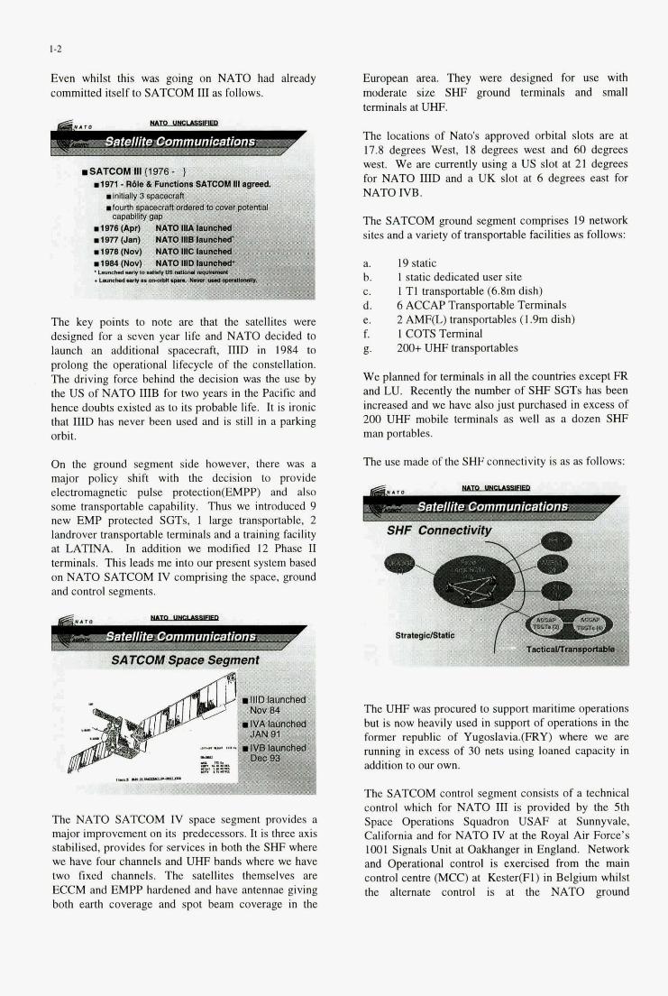
1-2
Even whilst this was going on NATO had already committed itself to SATCOM III as follows.
I B
The key points to note are that the satellites were designed for a seven year life and NATO decided to launch an additional spacecraft, IIID in 1984 to prolong the operational lifecycle of the constellation. The driving force behind the decision was the use by the US of NATO IIIB for two years in the Pacific and henee doubts existed as to its probable life. It is ironic that IIEI has never been used and is still in a parking orbit.
On the ground segment side however, there wm a major policy shift with the decision to provide electromagnetic pulse protection(EMPp) and also some transportable capability. Thus we introduced 9 new EMP protected SGTs. 1 large transportable. 2 landrover transportable terminals and a training facility at MTINA. In addition we modified 12 Phase Il trrminals. This leads me into our present system based on NATO SATCOM IV comprising the space, ground and control segments.
The NATO SATCOM IV space segment provides a major improvement on its predecessors. It is three axis stabilised, provides for services in both the SHF where we have four channels and UHF bands where we have two fixed channels. The satellites themselves are ECCM and EMPP hardened and have antennae giving both earth coverage and spot beam coverage in the
European area. They were designed for use with moderate size SHF ground terminals and small terminals at UHF.
The locations of Nato's approved orbital slots are at 17.8 degrees West, 18 degrees west and 60 degrees west. We are currently using a US slot at 21 degrees for NATO IIID and a UK slot at 6 degrees east for NATO IVB.
The SATCOM ground segment comprises 19 network sites and a variety of transportable facilities as follows:
a. 19 static b. c. d. 6 ACCAP Transportable Terminals e. f. I COTS Terminal g. 200t UHF transportables
We planned for terminals in all the countries except FR and LU. Recently the number of SHF SGTs has been increased and we have also just purchased in excess of 200 UHF mobile terminals as well as a dozen SHF man portables.
The use made of the SHF connectivity is as as follows:
1 static dedicated user site I TI transportable (6.8m dish)
2 AMFQ transportables (1.9m dish)
S@F Connectivity - / 3
8
The UHF was procured to support maritime operations but is now heavily used in support of operations in the former republic of Yugoslavia.(FRY) where we are running in excess of 30 nets using loaned capacity in addition to our own.
The SATCOM control segment consists of a technical control which for NATO III is provided by the 5th Space Operations Squadron USAF at Sunnyvale, California and for NATO IV at the Royal Air Force's 1001 Signals Unit at Oakhanger in England. Network and Operational control is exercised from the main control centre (MCC) at Kester(F1) in Belgium whilst the alternate control is at the NATO ground
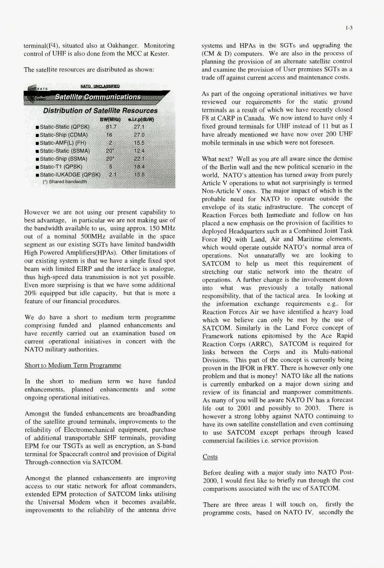
I -3
terminal(F4). situated also at Oakhanger. Monitoring control of UHF is also done from the MCC at Kester.
The satellite resources are distributed as shown:
Distribution of SWlite Resources .
.61allc-SIaUc (QPSK) .: mStalr-Ship (COMA)
mStatic-SIatk (SSMA)
mStats-Tl (OPSK) ',. . . '
W ~ I I C . A M F ( L ) (FH) : . ... j.
.slaUc-Shlp(SSMA) ' :
However we are not using our present capability to best advantage. in patticular we are not making use of the bandwidth available to us, using approx. 150 MHz ouf of a nominal 500MHz available in the space segment as our existing SGTs have limited bandwidth High Powered Amplifiers(HPAs). Other limitations of our existing system is that we have a single fixed spot beam with limited EIRP and the interface is analogue, thus high-speed data fransmission is not yet possible. Even more sqrising is that we have some additional 20% equipped but idle capacity, but that is more a feature of our finaneial procedures.
We do have a short to medium twm programme comprising funded and planned enhancements and have recently carried out an examination based on current operational initiatives in soneeFt with the NATO military authorities.
Short to Med ium Term Proeramme
In the short to medium term we have funded enhancemeilts, planned enhancements and some ongoing operational initiatives.
Amongst the. funded enhancements are broadbanding of the satellite ground terminals, improvements to the reliability of Electromechanical equipment, purchase of additional transportable SHF terminals, providing EPM for our TSGTs as well as encryption, an S-band tewinal for Spacecraft control and provision of Digital Through-connection via SATCOM.
Amongsf the planned enhancements are improving access to our static network for afloat commanders, extended EPM protection of SATCOM links utilising the Universal Modem when it becomes available, improvements to the reliability of the antenna drive
systems and HPAs in the SGTs and upgrading the (CM & D) computers. We are also in the process of planning the provision of an alternate satellite control and exanune the provision of User premises SGTs as a trade off against current access and maintenance costs.
As part of the ongoing operational initiatives we have reviewed our requirements for the static ground terminals as a result of which we have recently closed F8 at CARP in Canada, We now intend to have only 4 fixed ground terminals for UHF instead of 11 but as I have already mentioned we have now over 200 UHF mobile terminals in use which were not foreseen.
What next? Well as you are all aware since the demise of the Berlin wall and the new political scenario in the world, NATO's attention has turned away from purely Article V operations to what not surprisingly is termed Non-Article V ones. The major impact of which is the probable need for NATO to operate outside the envelope of its static infrastructure. The concept of Reaction Forces both Immediate and follow on has placed a new emphasis on the provision of facilities to deployed Headquarters such as a Combined Joint Task Force HQ with Land, Air and Maritime elements, which would operate outside NATO's normal area of operations. Not unnaturally we are loolung to SATCOM to help us meet this requirement of stretching our staIic network into the theatre of operations. A further change is the involvement down into what was previously a totally national responsibility, that of the tactical area. In looking at the information exchange requirements e.g.. for Reaction Forces Air we have identlfied a heavy load which we believe can only be met by the use of SATCOM. Similarly in the Land Force concept of Framework nations epitomised by the Ace Rapid Reaction Corps (ARRC), SATCOM is required for links between the Corps and its Multi-national Divisions. This part of the concept is currently being proven in the IFOR in FRY. There is however only one problem and that is money! NATO like all the nations is currently embarked on a major down sizing and review of its financial and manpower commitments. As many of you will be aware NATO IV has a forecast life out to 2001 and possibly to 2003. There is however a strong lobby against NATO continuing to have its own satellite constellation and even continuing to use SATCOM except perhaps through leased commercial facilities i.e. service provision.
Before dealing with a major study into NATO Post- 2000, I would first like to briefly run through the cost comparisons associated with the use of SATCOM.
There are three areas I will touch on, fustly the programme costs, based on NATO IV, secondly the
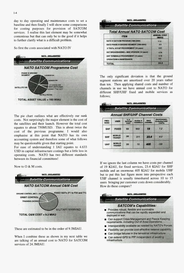
1 4
day to day operating and maintenance costs to set a baseline and then finally I will show some comparisons for costing purposes for provision of SATCOM services. I realise this last element may he somewhat contentious hut that can only be to the good if it helps to further clarify what is a difficult problem.
So first the costs associated with NATO IV
I ." .
The pie chart outlines what are effectively our sunk costs. Not surprisingly the major element is the cost of the satellites and their launch. However the total cost equates to about 750MUSD. This is about twice the cost of the previous programme. I would also emphasise at this point that NATO has its own aecounting system and therefore some of what follows may he questionable given that starting point. For eaSe of understanding 1 M U equates to 4.633 USD in capital infrastructure costings but a little less in operating costs. NATO has two different standards hetween its financial committees!
Now to 0 & M costs.
These are estimated to be in the order of 9.3MIAU.
When I combine these as shown in my next table we are talking of an annual cost to NATO for SATOM services of 24.3MIAU.
The only significant deviation is that the ground segment stations are amortised over 20 years rather than ten. Then applying shared costs and number of channels in use we have annual GO& to NATO for different SHFNHF fixed and mobile services as follows;
Satellite Communications
If we ignore the last column we have costs per channel of 19 KIAU, for fixed services, 23.4 KIAU for SHF mobile and an enormous 405 KIAU for mobile UHF hut to put this last figure more into perspective each UHF channel is usually timeshared across 10 to 15 users bringing per customer costs down considerahly. How do t h e GOmpUE?
Satellite Communications
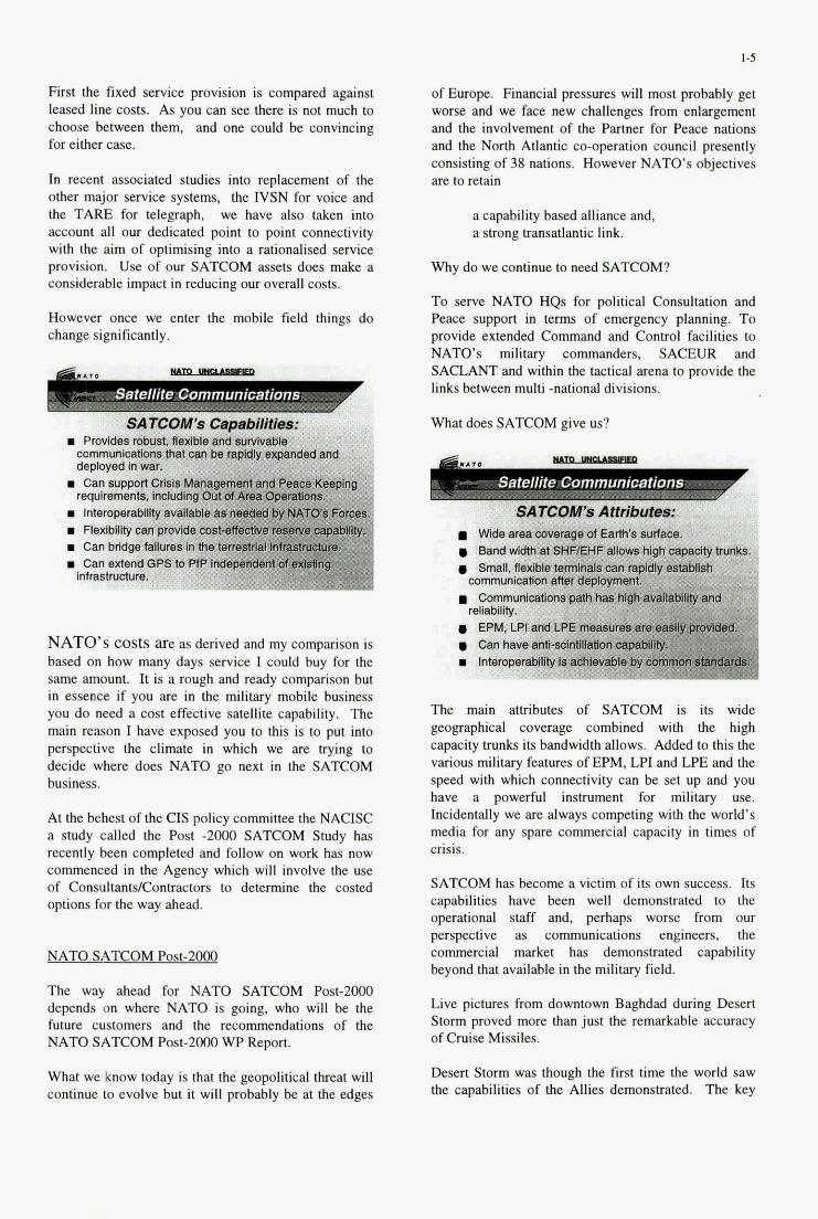
First the fixed service provision is compared against leased line costs. As you can see there IS not much to choose between them, and one could be convincing for either case.
In recent associated studies into replacement of the other major service systems, the IVSN for voice and the TARE for telegraph, we have also taken into account all our dedicated point to point connectivity with the aim of optimising into a rationalised service provision. Use of our SATCOM assets does make a considerable impact in reducing our overall costs.
However once we enter the mobile field things do change significantly.
NATO's Costs are as derived and my comparison is based on how many days service I could buy for the same amount. It is a rough and ready comparison but in essence if you are in the military mobile business you do need a cost effective satellite capability. The main reason I have exposed you to this is to put into perspective the climate in which we are hying to decide where does NATO go next in the SATCOM business.
At the behest of the CIS policy committee the NACISC a study called the Post -2000 SATCOM Study has recently been completed and follow on work bas now commenced in the Agency which will involve the use of ConsultantslContractors to determine the costed options for the way ahead.
NATO SATCOM Post-ZOO0
The way ahead for NATO SATCOM Post-2000 depends on where NATO is going, who will be the future customers and the recommendations of the NATO SATCOM Post-2000 WP Report.
What we know today is that the geopolitical threat will continue to evolve but it will probably be at the edges
of Europe. Financial pressures will most probably get worse and we face new challenges from enlargement and the involvement of the Partner for Peace nations and the North Atlantic co-operation council presently consisting of 38 nations. However NATO's objectives are to retain
a capability based alliance and, a strong transatlantic link.
Why do we continue to need SATCOM?
To serve NATO HQs for political Consultation and Peace support in terms of emergency planning. To provide extended Command and Control facilities to NATO's military commanders, SACEUR and SACLANT and within the tactical arena to provide the links between multi -national divisions.
What does SATCOM give us?
m
The main attributes of SATCOM is its wide geographical coverage combined with the high capacity trunks its bandwidth allows. Added to this the various military features of EPM, LPI and LPE and the speed with which connectivity can be set up and you have a powerful instrument for military use. Incidentally we are always competing with the world's media for any spare commercial capacity in times of crisis.
SATCOM has become. a victim of its own success. Its capabilities have been well demonstrated to the operational staff and, perhaps worse from our perspective as communications engineers, the commercial market has demonstrated capability beyond that available in the military field.
Live pictures from downtown Baghdad during Desert Storm proved more than just the remarkable accuracy of Cruise Missiles.
Desert Storm was though the first time the world saw the capabilities of the Allies demonstrated. The key

1-6
element that allowed the exercise of effective command and control of such a large, multinational fighting force was communications and SATCOM was pivotal in their provision.
In terms of its capabilities it:
a.
b.
Provides robust, flexible and survivable communications that can be rapidly expanded and deployed in war.
Can support Crisis Management and Peacekeeping requirements, including Out of Area Operations.
Interoperability available as needed by NATO's Forces.
Flexibility can provide cost-effective reserve capability.
Can bridge failures in the terrestrial infrastructure.
Can extend GPS to PE' independent of existing infrastructure.
Thus it allows us independence from the national infrastructure out of area, provides a bridge tu land systems on failure and has the potential to provide connectivity to our other allies.
SATCOM now has a proven track record in delivering these capabilities to both the politician and the commander.
Throughout the Cold War SATCOM formed a core element in our hardened communications infrastructure and in providing communications to the Fleet. However, our use of this capability had not been developed.
Elsewhere in France, the UK and the US national involvement in overseas operations has seen a radical change in attitude to the employment of SATCOM.
The working party considered all aspects of operating future SATCOM both military and commercial. All aspects were considered both commercial and military, what orbit should we go for. the shape of the future ground segment and how the capability should be controlled. In addition it looked into the vanous financial options for continuing to operate a military owned SATCOM system. In particular it looked at the consequences of trying to join one of the several consortia currently looking into the provision of new satellites in the early p art of the next century. These
were all compared with the use of commercial solutions either terrestrial or satellite and finally they evaluated their conclusions. Amongst the conclusions reached were the following:
a. NATO has a continuing requirement for a Military Satellite Communications.
b. The required assurance levels, when balanced against the threat, justify a military satellite.
c. The traditional Euro-Centric Coverage, provided by NATO IV, is inadequate to meet NATO's future needs.
d. From the financial analysis military SATCOM is cost effective for some fixed communications and all mobile communications.
The major conclusion reached was that NATO has a continuing requirement for a military satellite capability as the required service assurance levels when balanced against the forecast threat were considered to justify the military features. The coverage needs to he improved to take account of the changed political situation and from a financial viewpoint the equation in the case of fixed services is finely balanced.
The detailed report is in the policy areas of all the nations and goes into far more detail than I can cover today. 1 would like to highlight one particular aspect, no matter bow it is finally provided SATCOM has proved itself to be a force multiplier. Amongst the other conclusions were that:
a. Overall a mix of commercial SATCOM and a shared military constellation provides the least cost solution.
b. Current national space segments will require replacement in the 2003-2008 timeframe.
c. NATO's long term requirements are closely aligned with those of the International Military Consortia.
d. NATO is faced with a capability shortfall in the period 2001 through 2005.
In summary, a mixed system would provide the least cost option, NATO's future is probably allied to one of the consortia and finally an interim capability to meet the shortfall in the period 2001 to 2005 will be needed.

1-7
NATO needed to plan what it should do in the meantime to fill the gap in the 2001 to 2006 timeframe.
I have not strayed into the realms of what technology can do. E.g.. the use of SATCOM broadcast at 24MBh or tactical switched ATM services but have concentrated on defining why SATCOM will continue to dominate military planning. We leave it to the scientific community to define the art of the possible whilst we live in the arena of the affordable.
The workmg party's report made the following recommendations to its Policy Committee the NACISC that it:
a. Agrees that SATCOM is essential in extending communications to deployed and mobile forces.
Agrees that, whilst commercial SATCOM has a role, it does not provide the necessary EPM and EMPP.
b.
c. Invites the MNCs to produce their Post 2000 IERs (this task is now completed).
d. Notes that NATO will continue to require a military SATCOM Capability Post 2000.
Notes that, from a planning perspective, the NATO IV constellation requires replacement in 200 1.
e.
Thus, the key issues are that:
a. essential in extending the GPS to deployed and mobile forces of the Alliance and in the provision of SPS;
b. although commercial SATCOM can meet some of NATO's information exchange requirements, it cannot provide the necessary ECM and EMP countermeasures;
However the report highlighted the fact that the international military consortia were unlikely to provide a facility before 2004 at the earliest and
CONCLUSION
There are serious shortcomings in our present system, not all of the capacity is in use. The ITU frequency allocations preclude NATO's use of much of the mobile band. The satellite Antenna beam patterns and channelisation still reflect our cold war needs. We have continuously failed to ensure all aspects of the system are procured simultaneously and we do not manage it as an integrated sub-system of our communicatlons architecture. We are about to lose the capability at the turn of the century.
Post 2000 we will continue to focus on the SHF band for cost reasons and we will need to make much greater use of the mobile bands.
We will continue to place heavy reliance on military protection features; particularly the space segment will need to be hardened against limited threats e.g.. EMPP and we would seek diversified control under military management. We believe encrypted 'IT & C to be essential. Above all else if we are to stay in business we must continue to reduce costs wherever possible.

2-1
Possibilities and Limitations of Spaceborne S A R with Respect to Military Reconnaissance
W. Keydel DLR
Institut fik Hochfrequenztechnik Postfach 1 1 16
82234 Oberpfaffenhofen Germany
Summary SAR systems fix military applications have to be conside- red withrespect to the nquktnents d t i n g from speci- fic scenarios which are estimated by the objects to be observed. The most important reqkments for military reconnaiasance satellites are the geometrical resolution, the dimension of the covered area as well as timelining and the coverage repetition. The latter is strictly depen- dent on the satellites orbit, which leads to power require- ments.
2. S A R Basics and Specialities SAR systems are mainly characterized by electrical para- meters and observation geometry parameters 88 well Veq important electrical parameters for a radar are: fie- quency, antenna size with respective beamwidth and po- larization and the haasmitter power as well as the pulse
observation geometry are for spaceborne radars orbit altitu&. ami inclination as well as swath width and geome-
repetition fquency. Main characteristics with respect to
trical ground resolution
SynmetiC apermn radar systems have potential resolution Aspthetic aperture radar (SAR) is basically a real aper- capabilities nearly comparable with optical systems. The ture radar with very high sophisticated data evaluation image resolution as well as its conhast is *pent on ancl image processing. Basic of SAR is the construction of weather conditions and optical vision. Foliage penetra- a very long antenoa along the flight path (here aamuned as tion, principally, is possible and lower frequencies allow strongly linear) by means of data processing. Along the to some extent d a c e penetration also. flight path aF2 the measuring points for amplimde, phase
andfiquencyofthebackscatteredsignaLThisispriaci- Main restrictions of SAR are related to data processing, pallyanormal array. However, in a conventional apay all data handling and power requirements. Automatic real signals arrive at the same time and wil l be added at the time image analysis as well as image interpntation is not receiver input simultaneously. ‘Ihe synthetic aperture may yet possible at all. exist of one single element receiving the signals one after
the otber at the respective positions and store them COT-
However, special modes like Scan-SAR, Interfenrmetry, rectly with respect to amplitude, phase and position. In Look Steering and Spot Light, as well as multi mode and such a way the mal SAR antenna becomes the single multisateUecoaaplsseem to be able to overnome mauy element of a large (synthetic) array antenna. The stored limitations and to increase the efficiency of SAR systems echos can be added by a complicated data pmcessing and for military purposes drastically. in the image pmcwor the SAR image can be produced.
1. Introduction The most important equations whicb combine difFenmt SyntheticApermnRadar ( S ~ ~ ) i s e ~ ~ e l l e n t l y w i t e d f ~ SARparam~areg iWahTab le 1 [l, 21.Somespecia-
surveillance and mo-Ce wstents. lities of S A R become evident The azimuth resolution of SAFL principally, combines the advantages of mimwave a S A R is independent of wavelength and distance. and a systems like weather independence, &,,@gk capabfiv, better resolution can be nached with smaller real auten- penetration capability etc. with wavelength and distance is opposite to mal independent high resolution capabiliry. ~incipally, SAR ape- and 0h.r optical systems. For S A R the can detect, identify and man & and mm theoretical limit of azimuth ground resolution is given by point tagem as ell as area and volume targets. SAR also hdf- length in flight ~ c t i o n . range *- has 3 ~ d - i n g capability and possibility pendencyofthe mlution is a reason for the possibility to as well. he state ofthe art as well as the development of extent principally S A R ~II I~ with ~~ SY- techniques and techaologies needed and possible to apply with present and future requirements will be shown short- ly in order to point out the principal limitations as well as - equations & estab&& plincipsl technological the possibilities for military use. limits for the development and applications of spaceborne
S A R .
and not with k~ antennas.
On S P a c e b SY*m also.
Paper presenfed af the AGARD MSP P Symposium on “Space Sysfem as Conhibutors fo the NATO Defence Mission”, held in Cannes, France, 3.6 June 1996, and published in CP-580.
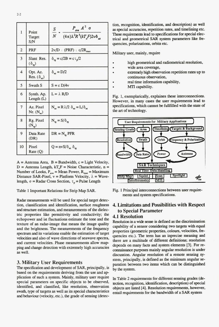
2-2
1 S P, A' a
Point -. Target N (4r)A2R'(kTf)2v6~ S I N
3 slant Res. 8,=cTzB = c r p (8,)
5
6
7
tion, rccognition, &milkah 'on, and description) as well M special accuTBcic8, repetition rates, and timelining etc. ' I b e s e q ' ' lead to specifications for special e h - t r i d and geometrical S A R system parameters urc fw quencies, polarizations, orbits etc.
d time infonuah capability, Swaths S-cDI4v MTI capability.
SyntaAp. L=rZRD Length (U AzPixel N,=RkD8,=48,
Fig. 1, exemplarically, explainfs these iatammd ons. However, in many casea the user requixements lead to specifiiations, which cannot be fullfilled with the state of the an of technology. Nr. (N,)
high geometrical and r a d i e 4 resolution, wide area c m g e , exmmlyhigh observation reptition rates up to continuous obsavation,
8 Rg. Pixel N,=S/8, (N,)
9 DataRate DR=N,PFR I (DR) I
A = Antenna Area, B = Bandwidth, c = Light Velocity. D = Antenna Length, kT$ = Noise Characteristic, n = Number of Looks. P, = Mean Power, R- =Maximum Distance SAR-Pixel, v =Platform Velocity, I =Wave- length, o = Radar Cross Section, zp = P u k Length
Table 1 Important Relations for Strip Map SAR.
Radar mmmmmfs will be used for special target detec- tion, claadfcation and identification, surface roughmss and srmctlrre estimation, and measuremenls of the dielec- tric properties like permittivity and condoctivi~ the echopower and ist fluctuations estimate the tone. and the texture of an rah-image that means the image quality and the brightness. 'RE measurements of the fresuency spectnrm and its variations enable the estimation of target velocities and also of wave directions of seawave spectra, and cut~ent velocities. phase measureme- allow map ping and change detection with exmmely high accuracias as well.
3. Military User Requirements 'Ihe specification and development of SAR, principally, is based on the requirements den* from the use and a p plication of such a system. M y , military user require special parameters on specific objects to be observed, identified, and classified, like nsolution, observation swath, type of targets as well as its special characteristics and behaviour (velcci~~, etc.), the grade of sensing (detec-
Fig. 1 Principal interconnections between user
4. Limitations and Possibilities with Respect
4.1 Resolution Rcsolutionina wide - is defined as the disaimina tion capability of a sensor considering two targets with equal properties (geometric properties, colours, velocities, fm- quencies etc.). The term has an inp~cise meaning and there are a multitude of different ddinitions: mlution depends on many facts and system elements [3]. For re- camkmcc purposes mainly angular xcsolution m under discussion. Angular resolution of a remote sensing sy- stem, principally, is dehed as the minimum angular se- paration between two items which can be distinguished by the system.
In Table 2 requirements for differenr sensing grades (de- tectioa, cognition, identitication, description) of special objects are listed [4]. Resolution mpkmenBs, however, entail ~qu inments for the bandwidth of a SAR system
ments and system 8pecifications.
to Special Parameter
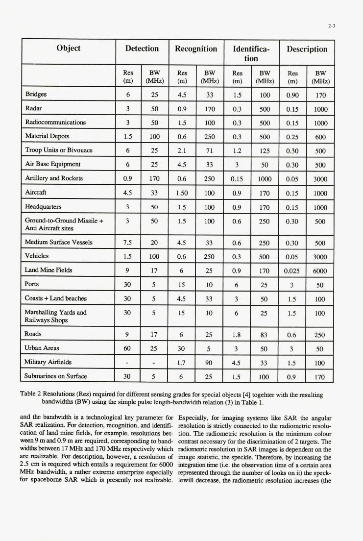
2-3
Object Detection Recognition Identifica- Description tion
Res BW Res BW Res BW Res BW (m) WW (m) W-W (m) WIZ) (m) W)
Bridges
I Radar I 3 I 50 I 0.9 I 170 I 0.3 I 500 I 0.15 I lo00 I 6 25 4.5 33 1.5 100 0.90 170
Radiocommunications
Material mpou
Troop Units or Bivouacs
3 50 1.5 100 0.3 500 0.15 lo00
1.5 100 0.6 250 0.3 500 0.25 600
6 25 2.1 71 1.2 125 0.30 500
Air Base Equipment 6 25 4.5 33 3 50 0.30 500
Artillery and Rockets 0.9 170 0.6 250 0.15 1000 0.05 3000
Aimaft 4.5 33 1.50 100 0.9 170 0.15 lo00
HeadqUarterS
Gmund-toGmund Missile + Anti Aircraft sites
Medium Surface Vessels
3 50 1.5 100 0.9 170 0.15 lo00
3 50 1.5 100 0.6 250 0.30 500
7.5 20 4.5 33 0.6 250 0.30 500
Vehicles 1.5 100 0.6 250 0.3 500 0.05 3000
Land Mine Fields 9 17 6 25 0.9 170 0.025 6OOO
Pons 30 5 15 10 6 25 3 50
Coasts +Land beaches
Matshauing Yards and Railways Shops
Roads
30 5 4.5 33 3 50 1.5 100
30 5 15 10 6 25 1.5 100
9 17 6 25 1.8 83 0.6 250
Urban Areas 60 25 30 5 3 50 3 50
Military Airfields
Submarines on Surface
- - 1.7 90 4.5 33 1.5 100
30 5 6 25 1.5 100 0.9 170
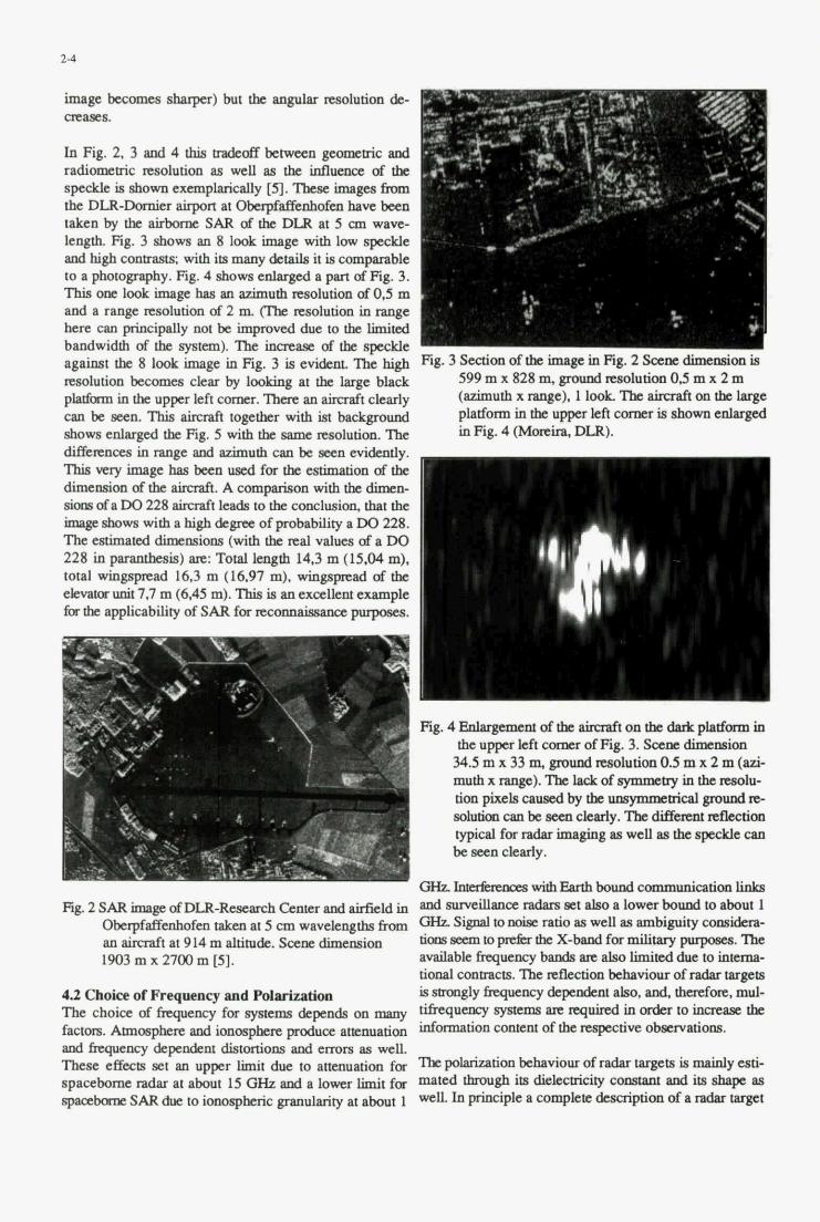
2-4
image bccolnas Bharpa) but the angular rssolutim de- otp(Ics.
I In Fig. 2 ,3 ad 4 lhis eadcotr between gunncpic and radiomstric d u t i m an Wll 811 the Mumre af tk
thc DLR-Dmnicr airport at O b @ E a W b have ken thlccn by the airbmnc SAR ofthe DLR at 5 an MID
length Fig. 3 shows an 8 look image with low spscklc Plrdhighcammsts withic3~&eailsitiscomprablc to a photognphy. Fig. 4 showaenlagsd a p m ofFig. 3. This om laokimap has an azimuth ~ ~ ~ l u t i o n af0.5 m and a range nsolution
bshownCXUllp~Cdy [5]. Thac h ~ h k l
m w mao~utim in range I .- . . . .. Y .. ._.
difscrrnas inrange and azimuth caa be accncvi&nUy. T U very h g e has bcen used f a the ewimation of tb
s i o m d a W 228 aimaft leada to tb c4mclwi011, that the m s b o w s with a high &lpk of probibility a W 228. Tbcewimateddimenslons ' (with tk mal valucs of a DO 228 in pararubesis) arc: Total lmgm 14.3 Q (15.04 m). total aringspread 16.3 m (16.97 m). wingspmd of the ehrstor uait 7,7 m (645 m). This is an exallat uample
dimMim afthe aimaft. A compprisan with the dimep
&r lk. applicsbility of SAR f a lemM&mw prrDo&s.
- !
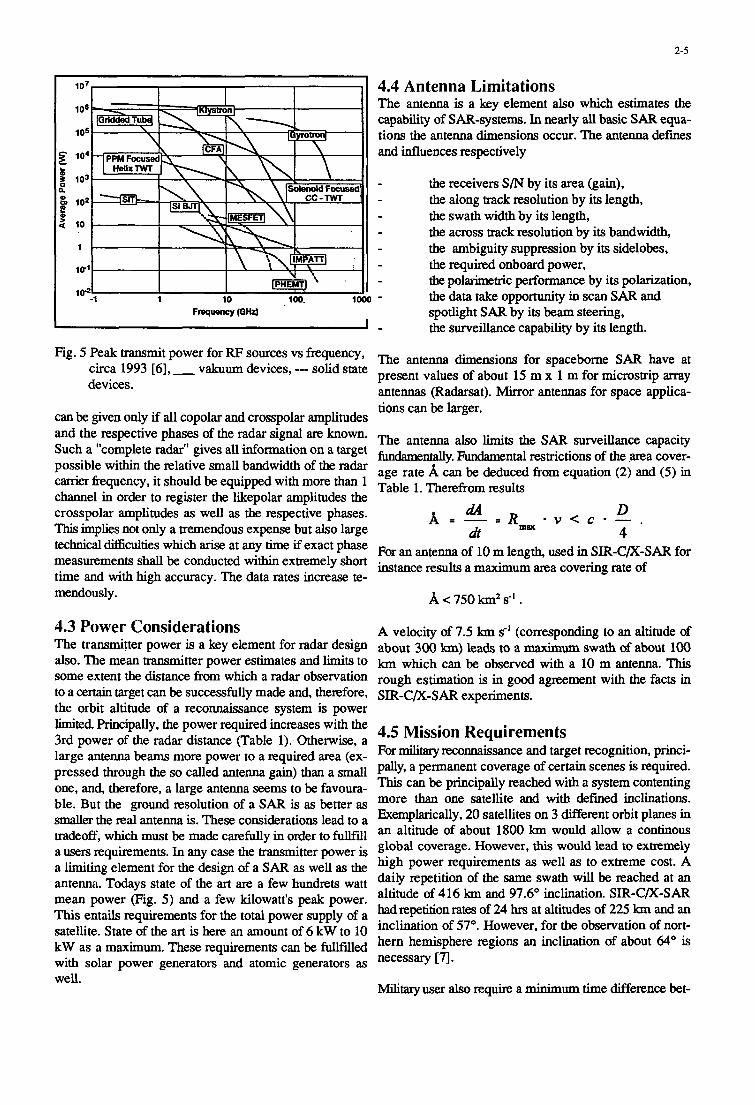
2-5
4.4 Antenna Limitations The antenna is a key element also which estimates the capability of SAR-systems. In nearly all basic S A R equa- tions the antenna dimensions occur. The antenna defines and influences respectively
the receivers S / N by its area (gain),
the swath width by its length, the a m s s track resolution by its bandwidth,
- the along track resolution by its length,
the ambiguity suppression by its sidelobes, - - the required onboard power,
the polarimetric performance by its polarization, the data take opportunity in scan SAR and spotlight SAR by its beam steering,
- the surveillance capability by its length.
Fig. peak transmit power for RF circa 1993 [61, - v a k u ~ devices, --- solid state present values of about 15 m x 1 m for microstrip
vs frequency* The ante- dimensions for spaceborne S A R have at
antennas (Radarsat). Mirror antennas for space applica- tions can be larger.
can be given only if all copolar and crosspolar amplitudes and the respective phases of the radar signal are known. The antenna also limits the sAR surveillance capacity Such a "complete r a h " gives all information on a target -dy. restrictions of the area cover- possible within the relative small bandwidth of the radar age rate A can be deduced - equation (2) and ( 5 ) in carrier fkquency, it should be equipped with more than 1 Table Therefrom results channel in order to register the likepolar amplitudes the
dA crosspolar amplitudes as well as the respective phases. A = - = R Lft
devices.
D 4
m ~ e ~ - - . max This implies not only a tremendous expense but also large ---
technical difliculties which arise at any time if exact phase For an antenna of lo measurements shall be conducted within extremely short time and with high accuracy. The data rates increase te-
length, used in sm-c/X-sAR for results a maximum area rate of
mendously .
4.3 Power Considerations A velocity of 7.5 km s-' (corresponding to an altitude of The transmitter power is a key element for radar design about 300 b) lea& to a swath of about 100 also. The mean transmitter power estimates and limits to km which can be observed with a 10 m antenna. This. some extent the distance from which a radar observation rough estimation is in g& agreement with the facts in to a certain target can be successfully made and, therefore, sm-c/x-s~~ experiments. the orbit altitude of a reconnaissance system is power
4.5 Mission Requirements limited Principally, the power required increases with the 3rd power of the radar distance (Table 1). Otherwise, a large ante- beams more power to a required m a (ex- For militarY recoMaissance and Wet pressed bough the so called a n t e a gain) than a small
PMci- scenes =quired. a permanent coverage Of
This can be principally reached with a system contenting one, and, therefore, a large antenna seems to be favoura- more than one satellite and with defined inclinations. ble. But the ground resolution of a SAR is as better as
smaller the real is. These lead to a Exemplarically, 20 satellites on 3 different orbit planes in
a users requirements. In any case the transmitter power is global coverage. However, this would lead to extremely a limiting element for the design of a sAR as well as the high power requirements as well as to extreme cost. A
daily repetition of the same swath will be reached at an antenna. Todays state of the art are a few hundrets watt altitude of 416 km and 97.6" inclination. SIR-C/X-SAR mean power (Fig. 5) and a few kilowatt's peak power. hadrepetitionrates of 24 hrs at altitudes of 225 km and an This entails requirements for the total power supply of a
satellite. State of the art is here an inclination of 57". However, for the observation of nort- hern hemisphere regions an inclination of about 64" is kW as a maximum. These requirements can be fullfiUed
with solar power generators and atomic generators as necessary [q.
tradeoff, which be made carefully in to fullfill an altitude Of about 1800 kill Would allow a COnthlOUS
of 6 kW to
well. Military user also require a minimum time difference bet-
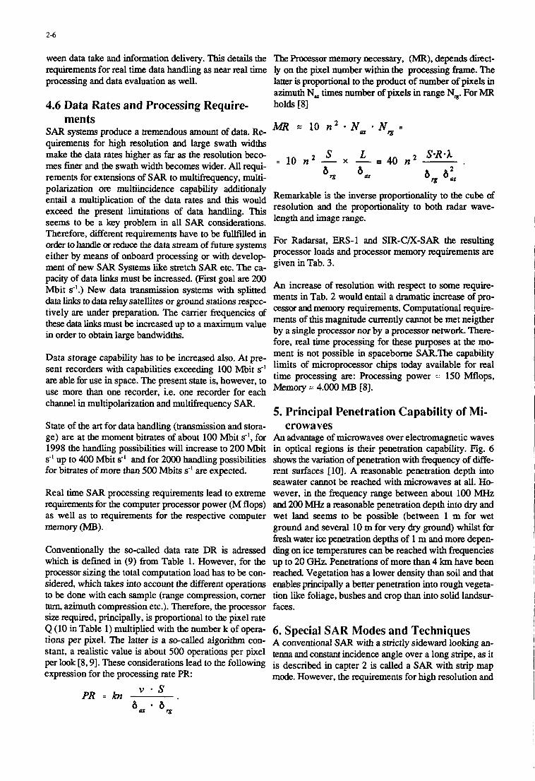
2-6
ween data take and infoxmation delivery. This details the The Processor memory necessary, (MR), depends direct- requirements for real time data handling as near real time ly on the pixel number within the processing frame. The processing and data evaluation as well. latter is proportional to the product of number of pixels in
azimuth N, times number of pixels in range N,. For MR 4.6 Data Rates and Processing Require- holds [SI
ments SAR systems produce a tremendous amount of data. Re- MR 10 n l * N u * N g = quirements for high resolution and large swath widths
I S L S-R * I make the data rates higher as far as the-resolution beco- mes finer and the swath width becomes wider. All requi- A A L - 1
= 10 n 1 - x - 40 n 2 (U e m 001
W W
rements for extensions of SAR to multifrequency, multi- T polarization ore multiincidence Capability additionaly entail a multiplication of the data rates and this would exceed the present limitations of data handling. This seems to be a key problem in all S A R considerations.
- Remarkable is the inverse proportionality to the cube of resolution and the proportionality to both radar wave- length and image range.
Therefore, different requirements have to be fullfilled in order to handle or reduce the data stream of future systems either by means of onboard processing or with develop ment of new SAR Systems like stretch S A R etc. The ca- given in Tab. 3.
For Radarsat, ERS-1 and SIR-C/X-SAR the resulting processor loads and processor memory requirements are
pacity of data links must be increased. (First goal axe 200 Mbit d.) New data transmission systems with splitted data links to data relay satellites or ground stations respec- tively are under preparation. The carrier frequencies d these data links must be increased up to a maximum value in order to obtain large bandwidths.
Data storage capability has to be increased also. At pre- sent recorders with capabilities exceeding 100 Mbit s-' are able for use in space. The present state is, however, to use more than one recorder, i.e. one recorder for each channel in multipolarization and multifrequency SAR.
State of the art for data handling (transmission and stora- ge) are at the moment bitrates of about 100 Mbit s-', for An advantage of microwaves over electromagnetic waves 1998 the handling possibilities will increase to 200 Mbit in optical regions is their penetration capability. Fig. 6 s" up to 400 Mbit 8' and for 2000 handling possibilities shows the variation of penetration with frequency of diffe- for bitrates of more than 500 Mbits s-' are expected. rent surfaces [lo]. A reasonable penetration depth into
seawater cannot be reached with microwaves at all. Ho- Real time S A R processing requirements lead to extreme wever, in the frequency range between about 100 MHz q u h m e n t s for the computer processor power (M flops) and 200 MHz a %asonable penetration depth into dry and as well as to requirements for the respective computer wet land seems to be possible (between 1 m for wet memory (MB). ground and several 10 m for very dry ground) whilst for
fiesh water ice penetration depths of 1 m and more depen- Conventionally the so-called data rate DR is adressed ding on ice temperatures can be reached with frequencies which is defined in (9) fi-om Table 1. However, for the up to 20 GHZ. Penetrations of more than 4 km have been processor sizing the total computation load has to be con- reached. Vegetation has a lower density than soil and that sidered, which takes into account the different operations enables principally a better penetration into rough vegeta- to be done with each sample (range compression, comer tion like foliage, bushes and crop than into solid landsur- turn, azimuth compression etc.). Therefore, the processor faces. size required, principally, is proportional to the pixel rate Q (10 in Table 1) multiplied with the number k of opera- 6. Special SAR Modes and Techniques tions per pixel. The latter is a so-called algorithm con- A conventional SAR with a strictly sideward looking an- Stant, a realistic value is about 500 operations per pixel @= d c o n ~ ~ incidence angle Over a long a it per look [8,9]. These considerations lead to the following is described in capter 2 is expression for the processing rate PR: mode. However, the requirements for high resolution and
An increase of resolution with respect to some require- ments in Tab. 2 would entail a dramatic increase of pro- cessor and memory requirements. Computational require- ments of this magnitude currently cannot be met neigther by a single processor nor by a processor network. There- fore, real time processing for these purposes at the mo- ment is not possible in spacebome SAR.The capability limits of microprocessor chips today available for real time processing are: Processing power z- 150 Mflops, Memory =: 4.000 MB [SI.
5. Principal Penetration Capability of Mi- crowaves
a SAR with smp
v - s 8 - 8
PR = kn ' u w
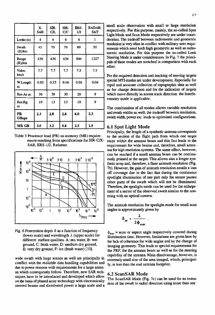
2-1
Table 3 Processor load (PR) an memory (MR) require- ments resulting from specifications for SIR-C/X- SAR, ERS-ID, Radarsat.
t 6 m -
h -- m 3.102 3.10 3 3.16’ 3 lo-*
.- 10” IO-~ I IO loz lo3 IO‘ i o5
. . h H z - I
small scale observation with small or large resolution respectively. For this purpose, mainly, the so-called Spot Light Mode and Scan Mode respectively are under consi- deration The tradeoff between radiometric and geometric resolution is very often in conflict with military user q u i - remenrs which need both high geometric as well as radio- metric resolution. For this purpose the so-called Look Steering Mode 6 under consideration. In Fig. 7 the princi- pals of these modes are scetched in comparison with each other.
For the required detection and tracking of moving targets special MTI-modes are under development. Especially for rapid and accurate collection of topographic data as well as for change detection and for the indication of targets which move directly in across track direction the Interfe- rometry mode is applicable.
The combination of all modes allows variable resolution and swath widths as well; the tradeoff between resolution, swath width, power etc. leads to optimised configurations.
6.1 Spot Light Mode Principally, the length of a synthetic antenna corresponds to the section of the flight path from which one target stays within the antenna beam and this fact leads to the requirement for wide beams and, therefore, small anten- nas for high resolution systems. The same effect, however, can be reached if a small antenna beam can be continu- ously pointed at the target. This allows also a longer syn- thetic array and, therefore, a finer azimuth resolution (Fig. 7b). However, the gain of azimuth resolution entails a loss off coverage due to the fact that during the continuous spotlight illumination of one part only the sensor passes other parts of the swath which will not be illuminated. Therefore, the spotlight mode can be used for the enlarge- ment of a sector of the observed swath similar to the zoo- ming with an optical camera.
The azimuth resolution for spotlight mode for small scan angles is approximately given by
a.
6.2 ScanSAR Mode na which consequently follow. Therefore, new S A R tech- niques have to be introduced and developed which allow on the basis of phased array technology with electronically steered beams and dismbuted power a large scale and a
The ScanSAR Mode (Fig. 7c) can be used for an exten- sion of the swath in radial direction using more than one
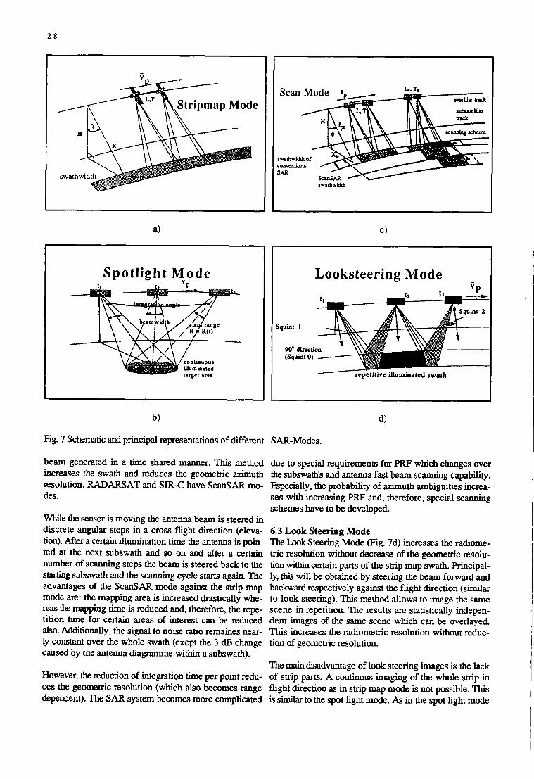
2-8
Spotlight M-ode
Fig. 7 Schematic and principal representations of different SAR-Modes.
beam generated in a time shared manner. This method due to special requirements for PRF which changes over increases the swath and reduces the geometric azimuth the subswath's and antenna fast beam scanning capability. resolution. RADARSAT and SIR-C have ScanSAR mo- Especially, the probability of azimuth ambiguities inma- des. ses with increasing PRF and, therefore, special scanning
schemes have to be developed. While the sensor is moving the antenna beam is steered in discrete angular steps in a cross flight direction (eleva- 6.3 Look Steering Mode tion). After a certain illumination time the antenna is poin- The b o k Steering Mode (Fig. 7d) increases the radiome- ted at the next subswath and so on and after a certain tric resolution without decrease of the geometric resolu- number of scanning steps the beam is steered back to the tion within certain parts of the strip map swath. Principal- starting subswath and the scanning cycle starts again. The ly, this will be obtained by steering the beam forward and advantages of the ScanSAR mode against the strip map backward respectively against the flight direction (similar mode are: the mapping area is increased drastically whe- to look steering). This method allows to image the same reas the mapping time is reduced and, therefore, the repe- scene in repetition. The results are statistically indepen- tition time for certain areas of interest can be reduced dent images of the same scene which can be overlayed. also. Additionally, the signal to noise ratio remaines near- This increases the radiometric resolution without reduc- ly constant over the whole swath (exept the 3 dB change tion of geometric resolution. caused by the antenna diagramme within a subswath).
The main disadvantage of look steering images is the lack However, the reduction of integration time per point redu- of strip parts. A continous imaging of the whole strip in ces the geometric resolution (which also becomes range fight direction as in strip map mode is not possible. This dependent). The S A R system becomes more complicated is similar to the spot light mode. As in the spot light mode
Looksteering Mode -
2-9
for look steering requirements result for the steering ca- bandwidth centered at 0 Hz images all targets of which pability of the antenna. A sufficient switch angle range (* the Doppler frequency seems to be 0 when the illumina- 10" for example) must be realised. The switch velocity tiondirection of the radar is orthogonal to the flight direc- must be high enough (1 O s-' for example) and the beam tion This is why fixed targets can be focused and positio- characteristic must be sufficiently independent from the ned precisely. switch angle over the whole range considered. Mostly critical, however, seems to be the scanning mechanism in However, targets which have a different relative speed to connection with the bandwidth required. the airplane than the fmed targets, might not be indicated
or focused, respectively. Depending on a different Dopp 6.4 SAR Interferometry ler kquency, they will be displaced to different positions S A R interferometry, mainly, is a technique for rapid and in the mgential displacement compared to the accurate collection of topo~aphic data, which is essential Original, real position is a direct measure for the radial for establishing digital elevation models. However, co- Velocity. herence measurements which are principally essential for interferometry allow change detection as well and here- The following methods represent the state Of the art af with special man target detection. Normally, interfe- with SAR: A radar With very high pulse repetition rometry works with two antennas separated in cross velo- frequency and a -OW -uth antenna beam is used. city direction. The distance between the two ante- is Moving targets can be perceived and their radial velocity the so-called basehe. Key of interferometry is the co- determined. For Slow moving objects a long antmm is herence of the signals received at both antenna positions. ScesSarY. The method, mainly, ~llows an accurate ~ x s U - This enables the measurement of the phase difference d rement Of radial moving targets [12]. hl addition the Use the both signals. This phase difference, principally, gives Of a radar System with two Or more a n t m ~ e displaced in
differences m c h g in one pixel and herefrom the along track direction is proposed in [ 13, 141. These a DEM can be evaluated. For spaceborne SAR, however, mAhods slow high imurate moving lmabt ion , two pass interferometry is state of the art, where the geo- determination and subclufier visibility. This metrical conditions with two separate measurements at similar to along track interferometry. The method is different times from the same satellite will be fullfilled Very Precise but needs higheff0-e @RS- 1, RADARSAT, SIR-C/X-SAR). ESA, presently, uses two satellites (ms- 1 and ms-2) in a tandem d- In 1151, a multilook method is proposed in which the posi- sion. State of the art is an altitude accuracy of about 10 m. tions Of moving targets are dekxmhed by observing se- With differential interferometry, which uses more than 2 veral images taken in a time series (multilook). In [I619
obtairaed The following formulas describe the principally fOCUShg objects is Proposed. The ComPutereffOfl possible altitude measurement accuracy, 6,, which is in 1151 and however, is Very high- reachable theoretically with a baseline B from a satellite in a distance R and a given phase accuracy 6 , for a verti- The method PrOPsed in [17] uses the reflection displace- cal across track antenna positions. ment method for analysis of the spectrum to detect, locali-
z and determine the tangential as well as the radial velo-
measurements, accuracies in the range 1 cm have been the use Of a Wigner Ville Distribution for detecting and
. - A * K Normalinterferometry: b,, E - 2 x B
A 4%
Differential interferometry: b , E - b
The latter formula points out the tremendous accuracy which can be reached. Technically feasable is 6, 2 5 O
which leads to a theoretical accuracy of 0.007 a. This points out why accuracies of better than 1 cm have been reached against point targets.
6.5 MTI Possibilities of Spaceborne SAR SAR, principally, has the ability for moving target indica- tion which is for military user very often both a strategic and tactical requirement. The Doppler coding of the recei- ved signals, which is produced by the movement of the carrier platform, is decisive for processing of SAR raw data. On principle a S A R processor with an azimuth
city of moving objects.
7. Conclusions S A R is an indispensable tool for military purposes. Its advantages are mainly weather independence, subsurface penetration capability and day and night capability. The resolution requirements for many reconnaissance purpo- ses generally can be fullfilled with the present state of the arts technology. The present main limitations due to tech- nological restrictions with respect to data handling and power alignment will be repressed within the next decade to levels which will allow high resolution observations with multipolarization and multifrequency systems over a wi& swath However, at present the resolution obtainable with optical spaceborne systems is an order better than that obtained with SAR and this fact seems to remain, even if the S A R capability increased. Therefore, S A R will be one component only in military systems as a valuable and necessary tool beside optical instruments.
2-10
References 340 as well as. 1.
2.
3.
4.
5.
6.
7.
8.
9.
10.
11.
12.
13.
Morchin, W., "Radar Engineers Source Book", Artech House, Boston, London, 1993. 14.
Keydel, W., "Basic Principles of SAR" and "SAR Pecularities, Ambiguities and Con- straints", in "Fundamentals and Special Pro- blems of Synthetic Apertwe Radar (SAR)", AGARDLS 182,1992. 15.
Forshaw, M.R.B.; Haskell, A.; Miller, P.F.; Stanley, D.J.; Townshend, J.R.G., in "Internat. Journal Remote Sensing", 1983, Vol. 4, No. 3, l6. pp. 497-520.
N.N., 'The implication of Establishing an Inter- national Satellite Monitoring Agency", United Nations Publication No. E.83.M.3., 1983.
Hom, R., "C-Band S A R Results Obtained by an Experimental Airborne SAR Sensor", in Proc.
17.
IGARSS, IEEE", 1989, pp. 2213-2216.
Evans, D.L. (Editor) et al., "Spaceborne Syn- thetic Aperture Radar: Current Status and Futu- re Dkctions", in "NASA Technical Memoran- dum" 4679,1995.
Cantatio, L.J., "Spacebased Radar Handbook, Chapter 1,2", Artech House, 1989.
Einstein, T.H., "Real-Time SAR Image Forma- tion Processing on a Multicomputer", Presenta- tion EUSAR '96, Konigswinter, Germany, 27.3.1996.
Otten, MP.G., "Comparison of Autofocus Algo- rithms", in "Military Microwaves", London, 1990, pp. 362-367.
CUR (1980) Conclusion of the Interim Meeting of Study Group 5 (Propagation in Nonionized Media), Genova, 16. June - 4. July 1980, Doc5/206E, 29.8.1980, Recommendation 527, pp. 38-44.
Moreira, J. et al., "X-SAR Interferometry: First Results, IEEE Trans. on Geosc. and Remote Sensing", Vol. 33, July 1995.
Freeman, A., "Simple h4TI using Synthetic Aperture Radar", in "IGARSS '84 Proc.", ESA SP215, 1984, pp. 65-70.
Klemm and Ender, "New Aspects of Airborne Radar h4TI", in "IEEE Roc., Internat. Radar Conference", Washington, May 1990, pp. 335-
Ender, J.H.G., "Detection and Estimation of Mo- ving Target Signals by Multi Channel SARI', in "EUSAR 96', Konigswinter, Germany, 1996. European Conference on Synthetic Aperture Radar, VDE-Verlag, 1996, pp. 411-417.
Ouchi, K., "On the Multilook Images of Moving Targets by SAR", in '?EEE Transactions", AP- 33, NO. 8, Aug. 1985, pp. 823-827.
Barbarossa, S. and Farina, A., "A Novel Proce- dure for Detecting and Focusing Moving Ob- jects with SAR Based on the Wigner-Ville Dis- tribution", in "IEEE Proc. Intemat. Radar Confe- rence, Washbgton, May 1990, pp. 44 to 50.
Moreira, J.R.; Keydel, W., "A new MTI-SAR Approach using the Reflectivity Displacement Method", in '?EEE Transactions on Geoscience and Remote Sensing", Vol. 33, No. 5, Sept. 1995.
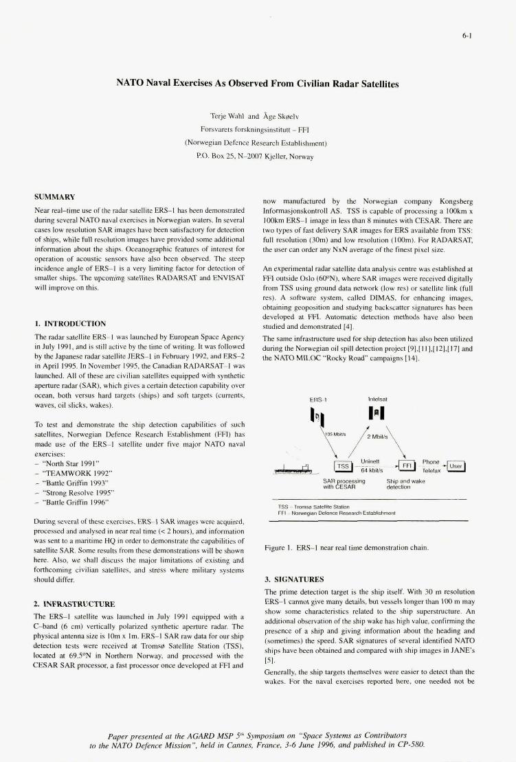
6-1
NATO Naval Exercises As Observed From Civilian Radar Satellites
Terje Wahl and Age Sk~elv
Forsvarets forskningsinstitutt - FFl
(Norwegian Defence Research Establishment)
P.0. Box 25. N-2W7 Kjeller. Norway
SUMMARY
Near realdme use of the radar satellite ER.-I has been demonstrated during several NATO naval exercises in Norwegian waters. In several cases low resolution SAR images have been satisfactory for detection of ships. while full resolution images have provided some additional information about the ships. Oceanographic features of interest for operalion of acoustic sensors have also been observed. The steep incidence angle of ERS-I is a very limiting factor for detection of smaller ships. The upcoming satellites RADARSAT and ENVlSAT will improve on this.
1. INTRODUCTION
The radar satellite ERS-I was launched by European Space Agency in July 1991. and is still active by the time of writing. It was followed by the Japanese radar satellite JERS-1 in February 1992. and ERS-2 in April 1995. In November 1995, the Canadian RADARSAT-I was launched. All of these are civilian satellites equipped with synthetic aperture radar (SAR), which gives a certain detection capability over ocean. both versus hard targets (ships) and soft targets (currents, waves, oil slicks. wakes).
To test and demonstrate the ship detection capabilities of such safellites. Norwegian Defence Research Establishment (FIT) has made use of the ERS-I satellite under five major NATO naval exercises: - "Norih Star 1991" - "TEAMWORK 1992" - "Battle Griffin 1993" - "Strong Resolve 1995" - "Battle Griffin 1996"
During several oftheseexercises. ERS-I S A R images w m acquired. pmcessed and analysed in near real time (< 2 hours). and information was sent to a maritime HQ in order to demonstrate the capabilities of satellite SAR. Some resulu from these demonstrations will be shown here. Also. we shall discuss the major limitations of existing and fonhcaming civilian satellites, and mess where military systems should differ.
2. INFRASTRUCTURE The ERS-I satellite was launched in July 1991 equipped with a C-band (6 cm) venically polarized synthetic aperture radar. The physical antenna size is IOm x Im. ER.-I SAR raw data for our ship dewtion lesls were received at Tromsg Satellite Station (TSS). located at 69YN in Northern Norway. and processed with the CFSAR S A R processor, a fast processor once developed at FFI and
now manufactured by the Norwegian company Kongsberg Informasjonskontmll AS. TSS is capable of processing a loOkm x IoOkm ERS-I image in less than 8 minutes with CESAR. There are two types of fast delivery SAR images for ERS available from TSS: full resolution (3Om) and low resolution (I&). For RADARSAT, the user can order any NxN average of the finest pixel size.
An experimental radar satellite data analysis centre was esrablished at FFl outside Oslo (WN), where SAR images were received digitally from TSS using ground data network (law res) or satellite link (full res). A software system, called DIMAS, for enhancing images, obtaining geopodtion and studying backscatter signatures has been developed at FFI. Automatic detection methods have also been studied and demonstmed [4]. The same infrasuuctun used for ship detection has also been utilized during the Norwegian oil spill detection project I91.[111,[121,I171 and theNAMMILOC"'RockyRoad"campaigns[14].
ERS-I lnlelsal
TS6 - Tmmss Sat~telllte Slation FFI - Nomegm oefsnce Re& Ealablishmsnf
Figure 1. ERS-I near real time demonstration chain
3. SIGNATURES The prime detection target is the ship itself. With 30 m resolution ERS-1 cannot give many details, but vessels longer than 100 m may show some characteristics related to the ship superstructure. An additional obsewation of the ship wake has high value, confirming the presence of a ship and giving information about the heading and (sometimes) the speed. S A R signatures of several identified NATO ships have been obtained and compared with ship images in JANE'S [SI. Generally. the ship targets themselves were easier to detect than the wakes. For the naval exercises reported here, one medd not be
Paper presented at the AGARn MSP 5Ih Symposium on "Space Systems as Connibuwrs 10 the NATO Defence Mission", held in Cannes, France, 3-6 June 1996, and published in CP-580.
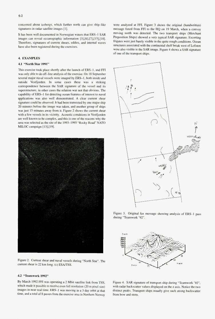
62
concerned about icebergs, which funher north can give shiplike signatures in radar satellite images [I].
It has been well documented in Norwegian waters that ERS-I SAR images can reveal oceanographic information [31.[61.[71.~151.[181. Therefore, signatures of eurrent shears. eddies, and internal waves have also been registered during the exercises.
4. EXAMPLES
4.1 “North Star 1991”
This exercise took place shortly after the launch of ERS-I, and FFI was only able to do off-line analysis of the exercise. OR 18 September several major naval vessels wen imaged by ERS-I. both inside and outside Veslfjorden. In some cases there was a striking compondence between the SAR signature of the vessel and its superstructure. in other cases the relation was not that obvious. The capability of E R S I for detecting ocean features of interest to naval applications was also well demonsirated. A clear current shear signature could be observed. It had been lransected by one major ship 20 minutes before the image was taken. and another gmup of ships was just 15 minutes away from it. Figure 2 shows the current shear with a few vessels in its vicinity. Acoustic conditions in Vestfjorden are well known to be complex, and this is one of the reasons why the area was selected as the site of the 1993-1995 “Rocky R o d NATO moc campaign [131,[191.
were analyzed at FFl. Figure 3 shows the original (handwritten) message faxed hom FFl to the HQ on 19 March. when a convoy moving north was detected. The two transport ships (Merchant Preposition Ships) showed a very typical SAR signa&. &coning frigates were just barely visible in the quite rough conditions. Ocean ~ t ~ c h l r e s associated with the continental shelf break west of Lofoten were also visible in the S A R image. Figure 4 shows a SAR signahln of one of the uansport ships.
rJ r
Figure 3. Original fax message showing analysis of ERS-I pass during ‘Teamwork ’92”.
171.
Figure 2. Cumnt shear and naval vessels during “North Star”. The current shear is 22 km long. (c) ESAmSS.
4.2 ‘ T ~ w o r k 1992”
By March 1992 FFI was operating a 2 Mbit satellite link from TSS, which made it possible to receive even full resolution (20 m pixel size) images in near real time. ERS-I was moving in a 3 day ohit at that time. and a total of 8 passes from the exercise area in Northem Nomay
Figure 4. S A R signa- of transport ship during ‘Teamwork ‘92”, with radar backscatter values displayed on the z axis. Notice the two distinct peaks. Transport ships usually give such stmng backscatter from bow and stern.
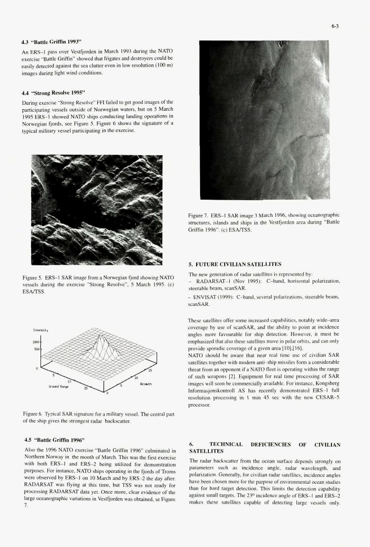
1 -- - . __
4.3 ‘%ttle GrifRn 1993”
An Em-I pass over Vestfjorden in March 1993 during the NATO exercise ‘Battle Griffin” showed that frigates and destroyers could be easily &wed against the sea clutter even in low resolution (100 m) images during light wind conditions.
4.4 “Strong Resolve 19%”
During exercise “Strong Resolve” FFl failed lo get good images of the participating vessels outside of Norwegian waters, but on 5 March 1995 ERS-I showed NATO ships conducting landing operations in Norwegian fjords, see Figure 5. Figure 6 shows the signature of a typical military vessel participating in the exercise.
Figure 5. ERS-I SAR image from a Norwegian fjord showing NATO vessels during the exercise ”Strong Resolve”. 5 March 1995. (c) ESAITSS.
Figure 6. Typical S A R signature for a military vessel. The central pan of the ship gives the strongest radar backscatter.
4.9 “Battle Griffin 1996’
Also the 1996 NATO exercise “Battle Griffin 1996” culminated in Northem Norway io the month of March. This was the first exercise with both E R S I and ERS-2 being utilized for demonstration purposes. For instance. NATO ships Operating in the fjords ofTroms were observed by ERS-1 on IO March and by ERS-2 the day &er. RADARSAT was flying at this time. but TSS was not ready for processing RADARSAT data yet. Once more, clear evidence of the large oceanogtaphic variatiom in vestfjorden was obtained, se Figure 7.
6.3
Figure I. ERS-I SAR mage 3 March 1996, showing oceanographic smctures. islands and ships in the Vestfjorden area dunng “Battle Gnffin 1996”. (c) ESAITSS.
5. FUTURE ClVlLUN SATELLITES
The new generation of radar satellites is represented by: - RADARSAT-I (Nov 1995): C-band, horisontal polarization. steerable beam xanSAR. - ENVISAT (1999): C-lmnd. several polarizations. steerable beam. scanSAR.
These satellites offer some increased capabilities, notably w i d e m a coverage by use of scanSAR. and the ability to point at incidence angles more favourable for ship detection. However, it must be emphasized that also these satellites move in polar orbits. and can only provide sporadic coverage of a given area [10].[16]. NATO should be aware that near real time use of civilian SAR satellites together with modern anti-ship missiles form a considerable threat from an opponent if a NATO fleet is OperaIing within the range of such weapons (7.1. Equipment for real time processing of S A R images will soon be commercially available. For instance, Kongsberg Informasjonskontroll AS has recently demonstrated ERS-I full resolution pmcessing in 1 min 45 sec with the new CESAR-5 processor.
6. TECHNICAL DEFICIENCES OF ervILIAN SATELLITES
The radar backscarter from the ocenn surface depends strongly on parameters such as incidence angle. radar wavelength. and polarization. Generally, for civilian radar satellites. incidence angles have been chosen more for the pulpase of environmental ocean studies than for hard target detection. This limits the detection capability against small targets. The 23O incidence angle of ERS-I and ERS-2 makes these satellites capable of detecting large vessels only.
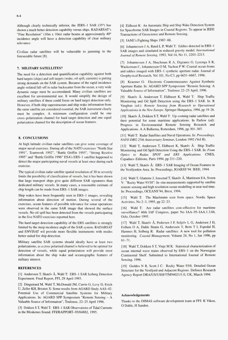
6-4
Although clearly technically inferior, the JERS-I SAR (3S0) has shown a much bener detection capability versus ships. RADARSAT'S "Fine Resolution" (IOm x lam) radar beams at approximately 400 incidence angle will have a detection capability of clear military relevance.
Civilian radar satellites will be vulnerable to jamming in the foreseeable future [SI.
7. MILITARY SATELLITES?
The need for a detection and quantification capability against both hard targets (ships) and soft targets (wake, oil spill, currents) is putting strong demands on the SAR system. Because of the rapid incidence angl-lated fall-aff in radar backwaner from the ocean. a very wide dynamic range must be accomcdated. Many civilian satellites are excellent for environmental use. It would simplify the design of military satellites if these could fonu on hard target deleaion only. However. if both ship s~perstructure and ship wake information from the same satellite are considered essential, the SAR instrument clearly m s t be complex. A minimum configuration could be one cross-polarization channel for hard target detection and one equal polarization channel far the description of ocean features.
8. CONCLUSIONS
At high latitude civilian radar satellites can give some coverage of major naval exercises. During all of the NATO exercises "North Star 1991". Teamwork 1992". "Banle Griftin 1993". "Smng Resolve 1995" and "Baftle Griftin 1996 BA's ERS-I satellite h a p p e d to detect the major participating naval vessels at least once during each exercise.
The typical civilian radar safellife spatial resolution of 30 m severely limits the possibility of classification of vessels, but it has been shown that large transpon ships give quite different SAR signatures than dedicated military vessels. In many cases, a reasonable estimate of ship length can be made from ERS-I SAR images.
Ship wakes have been frequently seen in ERS-I images, revealing information about direction of motion. During several of the exercises. ocean features of possible relevance for sonar operations were observed in the same S A R image that showed the surface vessels. No oil spill has been detected from the vessels participating in the five NATO exercises reported here.
The hard target detection capability of the ERS satellites is strongly limited by the steep incidence angle of the SAR system. RADARSAT and ENVISAT wil provide more flexible insrmmenfs with modes bener suited for ship detection.
Military satellite SAR systems should ideally have at least two polarizations, as a cross polarized channel is believed lo be optimal for detection of vessels, while equal poiarizafion will provide most information about the ship wake and oceanographic features of military interest.
REFERENCES
[ I ] Anderssen T. Skeelv A, Wahl T: ERS-I SAR Iceberg Detection Experiment. Final Repon, FFI. 29 April 1993. [21 Dinguirard M, Wahl T. McDonald JM, Carrin G. Levy D. Erich U. Zeller KH, Briotfet X Some results from AGARD Study AAS-42 Potential Use of Commercial Satellite Systems for Military Applications. In: AGARD SPP Symposium "Remote Sensing - A Valuable Source of Information", Toulouse, 22-25 April 1996. [31 Doken S T, Wahl T: ERS-I SAR Observafions of lldal Currents in the Moskenes Sound. FFlIRApwRT-95lD1882.1995.
[4] Eldhuset K An Automatic Ship and Ship Wake Detection System for Spacebome SAR Images in Coastal Regions. To appear in lEEE TransaEtions of Geoscience and Remote Sensing.
[5] JANE'S Fighting Ships 1987-88. [6] Johannessen J A, Reed L P, Wahl T: Eddies detected in ERS-I SAR images and simulated in reduced gravity model. International Journal of Remotr Sensing. 1993, Vol 14. No I I , 2203-2213.
[7] Johannessen J A, Shuchman R A, Digranes G, Lyzenga S R, Wackerman C. Johannessen 0 M. Vachon P W. Coastal ocean fronts and eddies imaged with ERS-1 synthetic apenure radar. Journal of Geophysical Research, Vol 101. No C3. pp 6651-6667, 1996.
[SI Kraemer 0: Electronic Countermeasures Against Synthetic Aperture Radar. In: AGARD SPP Symposium '*Remote Sensing: A Valuable Source of Information". Toulouse 22-25 April. 1996.
[91 Skeelv A, Anderssen T, Eldhuset K, Wahl T: Ship Traffic Monitoring and Oil Spill Detection using the ERS-I SAR. In: R Vaughan (ed.): Remote Sensing fmm Research to Opcrationol Applicarions in rhc New Eumpe. Springer Hungarica. 1994. pp 19-26.
[IO] Skblv A. Lhkken S T. Wahl T Upcoming radar satellites and their potential for some maritime applications. In Parlow (ed): Progress in Environmental Remote Sensing Research and Applications. A A Balkema, Rotterdam, 1996, pp 30-307.
[ I 1 1 Wahl T Radar Satellites and Naval operations. In: Pmccedings, NATO DRG 25th Anniversary Seminar, London 1992 (Vol m. [I21 Wahl T, Anderssen T, Eldhuset K, Skeelv A: Ship Trafftc Monitoring and Oil Spill Detection Using the ERS-I SAR. In: Fmm Optics to Radar, SPOT nnd ERS Applications. CNES. Cepadues-Editions. Paris 1994, pp 21 1-220.
[I31 Wahl T, Sk0elv A: ERS-I S A R Imaging of Ocean Feahlres in the Vestfjorden Area. In: Proceedings, IGARSS'94. IEEE, 1994.
[ 141 Wahl T. Glaneve 1, Ienserud T, Sk0elv A, Marfinsen EA, Sveen V: "Rocky Water 93/10": Imitu measurements supponed by satellite remote sensing and high resolution ocean modelling in near real time. In: Proceedings, OCEANS'M. BWSL 1994. [IS] Wahl T: The Maelswm seen from space. Nordic Space Activities, No 2-3, 1995. pp 22-23.
[I61 Wahl T: Are radar satellites cost-effective for maritime surveillance? 46th IAF Congress, paper No IAA-95-IAA.1.3.04. Oslo, October 1995. [ 171 Wahl T. Skeelv A. Pedersen J P, Seljelv L G. Andersen I H, Follum 0 A. Dahle Stwm G, Anderssen T, Bern T 1. Espedal H, Hamnes H. Solberg R Radar satellites: A new tool for pollution monitoring. Coastal Management. Volume 24, No I . Jan 1996. pp 61-71. [IS] Wahl T, Dokken S T, Vinje M K: Statistical characterization of ocean internal wave trains observed by ERS-I on the Norwegian Continental Shelf. Submitted to International Journal of Remote Sensing, 1996.
[I91 Geddes N R. Scott J C Rocky Water 93/6. Defailed Ocean Svuchlre for the Vestfjord and Adjacent Regions. Defence Research Agency Report DRAAJSNSSFfEM94021/1.0, UK, March 1994.
Acknowledgementr
Thanks to the DIMAS software development team al FFl: K Vien. 0 Dahle, H Sanden.
I I
, :
t I
This page has been deliberately left blank.

This page has been deliberately left blank.
7- 1
Radar Backscatter Statistics from the Sea Surface: Implications of SIR-CK-SAR Observations for Maritime Surveillance
J. T. Macklin I, N. R. Stapleton I", N. A. Robertson ' and R. Ringrose'
' GEC-Marconi Research Centre, Great Baddow, Chelmsford, Essex CM2 8HN, England.
* present address: Defence Research Agency, Winfrith, Dorset DT2 8XJ, England.
Defence Research Agency, Farnborough, Hants. GU14 6TD, England.
SUMMARY
Multi-channel synthetic-aperture radar (SAR) observations from the SIR-C/X-SAR experiment in the N. E. Atlantic (April 1994) are analysed, to test models of both the mean and the distribution of radar backscatter from the sea surface. The data cover incidence angles from about 20" to 40°, and wind speeds from about 5 to IO m s-'. Empirical and theoretical models of the mean fit the data well at C band, to an accuracy of 1 - 2 dB. Discrepancies at L and X bands point to needs for better empirical models at these frequencies, and for modifications to existing descriptions of short-wave spectra in theoretical models. Single-look SIR- C/X-SAR data (spatial resolution - 7 - 10 m) fit well to a K distribution, but multi-look data (spatial resolution - 25 m) fit a lognormal distribution. The observed second moments can be explained by the modulations of resolved ocean- surface waves, but only if relatively large hydrodynamical modulations are assumed. Swell-wave modulations are sometimes significantly larger at X band than at C and L bands. The implications of these results for the false-alarm rates in marine-target detection are discussed.
1. INTRODUCTION
With the development of wide-swath techniques for the Canadian RADARSAT satellite and the European Space Agency's planned Envisat satellite, the potential of spaceborne synthetic-aperture radar (SAR) for routine maritime surveillance is of increasing interest. The ability to detect targets is influenced not only by the mean but also by the distribution of backscattered returns from the sea surface. The distribution determines the frequency of occurrence of 'false-alarm' detections.
The behaviour at grazing incidence is relatively well established. There, departures from Rayleigh amplitude- statistics, in the form of spiky, high-amplitude returns, become more prominent as the spatial resolution becomes finer. Hence the optimum solution for maritime surveillance at grazing incidence is not necessarily to make the spatial resolution as fine as possible. There have been much fewer studies at the moderate incidence angles (typically 20' to 50') relevant for spaceborne SAR. Some studies with
ground-based radars (e.g. Thompson & Gotwols 1994 [I]; Gotwols & Thompson 1994 [2]) show that departures from Rayleigh amplitude-statistics also occur at moderate incidence angles, but with a different distribution to the grazing-incidence case. Hence the preferred radar parameters for maritime surveillance from spaceborne SAR are not yet clear. In order to address this subject, we analyse data from the Shuttle Imaging Radar, SIR-C/X-SAR, mission in April 1994. This mission obtained an extensive set of data over the N. E. Atlantic, where the ocean was imaged simultaneously at different radar frequencies and polarisations. Supporting in-situ measurements were also made to characterise the environmental conditions. In this paper we show how the analysis of this data-set can test and improve our understanding of the behaviour of both the mean backscatter and the backscatter distribution, and hence lead to an appropriate selection of image-threshold parameters for maritime surveillance using spaceborne SAR.
Section 2 describes the observed behaviour of the mean radar backscatter in the SIR-C/X-SAR data-set, and its interpretation in terms of models of the scattering from the sea surface. Section 3 then considers the observed characteristics and modelling of the distribution of radar backscatter. The implications for maritime target detection are then discussed in Section 4, and the conclusions of this paper are summarised in Section 5 .
2. MEAN RADAR BACKSCATTER
The SIR-C/X-SAR data-set analysed here has the following key features:
(i) It covers an extensive range of SAR parameters, namely: - simultaneous observations in L, C and X bands - dual polarisation (HH and VV) at L and C bands, and VV polarisation at X band - incidence angles covering the range from about 20' to 40'. (HH signifies horizontal polarisation transmitted and received; similarly VV signifies vertical polarisation.) Spatial resolutions are about 25 m for the multi-look data, and about 7 - 10 m for the single-look data which are also available in some cases.
(ii) The SAR data have been calibrated as a result of efforts throughout the mission, thus allowing predictions of
Paper presented at the AGARD MSP 5Ih Symposium on "Space Systems as Contributors to the NATO Defence Mission", held in Cannes, France, 3-6 June 1996, and published in CP-580.
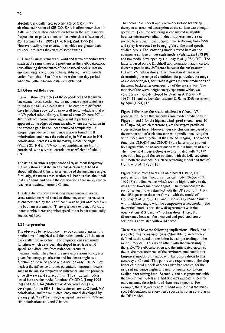
7-2
absolute backscatter cross-sections to be tested. The absolute calibration of SIR-C/X-SAR is often better than 1 - 2 dB, and the relative calibration between the simultaneous frequencies or polarisations can be better than a fraction of a dB (Freeman et al. 1995a [3] & b [4]; Zink 1995 [5]). However, calibration uncertainties which are greater than this occur towards the edges of some swaths.
(iii) In-situ measurements of wind and wave properties were made at the same times and positions as the SAR data-takes, thus allowing dependences of the observed backscatter on environmental conditions to be established. Wind speeds varied from about 5 to 10 m s-' over the nine-day period when the SIR-C/X-SAR data were obtained.
2.1 Observed Behaviour
Figure 1 shows examples of the dependences of the mean backscatter cross-section, oo, on incidence angle which are found in the SIR-CIX-SAR data. The data from different days lie within a few dB of an overall trend, which is that oo in VV polarisation falls by a factor of about 20 from 20" to 40' incidence. Some more significant departures are apparent at the edges of some swaths, where the variation in the antenna gain has not been removed completely. A steeper dependence on incidence angle is found in HH polarisation, and hence the ratio of oo in VV to that in HH polarisation increases with increasing incidence angle (Figure 2). HH and VV complex amplitudes are highly correlated, with a typical correlation coefficient of about 0.9.
The data also show a dependence of oo on radar frequency. Figure 3 shows that the mean cross-section at X band is about half that at C band, irrespective of the incidence angle. Similarly, the mean cross-section at L band is also about half that at C band, and hence the observations here imply that oo reaches a maximum around C band.
The data do not show any strong dependences of mean cross-section on wind speed or direction, or on the sea state as characterised by the significant wave height obtained from the buoy measurements. There is a weak tendency for oo to increase with increasing wind speed, but it is not statistically significant here.
2.2 Interpretation
The observed behaviour here may be compared against the predictions of empirical and theoretical models of the mean backscatter cross-section. The empirical ones are model functions which have been developed to retrieve wind speeds and directions from radar-scatterometer measurements. They therefore give expressions for oo at a given frequency, polarisation and incidence angle as a function of the wind speed and direction only. Hence they neglect the influence of other potentially important factors such as the air-sea temperature difference, and the presence of swell waves and surface films. The empirical models tested here are the model functions CMOD-3 (Long 1995 [6]) and CMOD-4 (Stoffelen & Anderson 1993 [7]), developed for the ERS-I wind scatterometer at C band, VV polarisation, and the multi-frequency model developed by Snoeij et al. (1992) [8], which is tested here in both VV and HH polarisations at L and C bands.
The theoretical models apply a rough-surface scattering theory to an assumed description of the surface wave-height spectrum. (Volume scattering is considered negligible because microwave radiation does not penetrate the sea surface to any significant degree. The scattering from foam and spray is expected to be negligible at the wind speeds studied here.) The scattering models tested here are the composite-surface or two-scale model (Valenzuela 1978 [9]) and the model developed by Holliday et al. (1986) [lo]. The latter is based on the Kirchhoff approximation, and therefore does not predict any difference between the backscatter in HH and VV polarisations. Our interest in it here is in determining the range of conditions (in particular, the range of incidence angles) for which it gives reliable predictions of the mean backscatter cross-section of the sea surface. The models of the wave-height energy spectrum which we consider are those developed by Donelan & Pierson (DP, 1987) [ I I ] and by Donelan, Banner & J a n e (DBJ) as given by Ape1 ( 1 994) [ 121.
Figure 4 illustrates the results obtained at C band, VV polarisation. Note that we only show model predictions in Figures 4 and 5 for the highest wind speed encountered, 10 m s-' upwind, which therefore gives the largest predicted cross-sections here. However, our conclusions are based on the comparison of each data-take with predictions using the wind speed and direction at the time of imaging. The model functions CMOD-4 and CMOD-3 (the latter is not shown) both agree with the observations to within a fraction of a dB. The theoretical cross-section is overestimated with the DP spectrum, but good fits are obtained with the DBJ spectrum, with both the composite-surface scattering model and that of Holliday et al. (1986) [IO].
Figure 5 illustrates the results obtained at L band, HH polarisation. This time, the empirical model (Snoeij et al. 1992 [8]) predicts values which are too high relative to the data at the lower incidence angles. The theoretical cross- section is again overestimated with the DP spectrum. Here the DBJ spectrum does not fit well with the model of Holliday et al. (1986) [IO], and it shows a systematic misfit with incidence angle with the composite-surface model. The theoretical models also show disagreements with the observations at X band, VV polarisation. There, the discrepancy between the observed and predicted cross- sections is correlated with wind speed.
These results have the following implications. Firstly, the predicted mean cross-section is obtainable to an accuracy, defined as the standard deviation in a single reading, in the range 1 to 2 dB. This is consistent with the uncertainty in the SIR-C/X-SAR calibration and the anticipated errors in the in-situ measurements of the environmental conditions. Empirical models only agree with the observations to this accuracy at C band. This points to a requirement to develop better empirical models at other radar frequencies, for the range of incidence angles and environmental conditions available for testing here. Secondly, the disagreements with the theoretical models at L and X bands indicate a need for more accurate descriptions of short-wave spectra. For example, the disagreement at X band implies that the wind- speed dependence in short-wave spectra is not as severe as in the DBJ model.
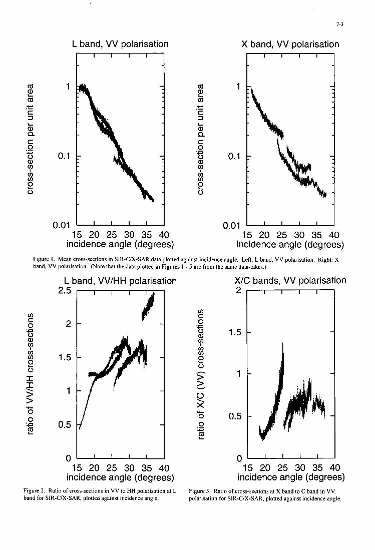
1-3
1 -
0.5
cd
cd
c 3
a, Q c 0 0 a,
v) v)
0
2 c, .-
L
.- +
?
2
-
L band, VV polarisation - t 1
1
0.1
cd
cd
c 3
a, Q c 0 0 a,
v) v)
0
2 c, .- L
.- c.
?
2
X band, VV polarisation
7 t 1
0.1
v) c 0 0 a,
v) v)
0
.- c,
?
2 I I > > \
+ 0 0 .- c,
2
0.01 - 15 20 25 30 35 40
incidence angle (degrees)
0.01 15 20 25 30 35 40
incidence angle (degrees) Figure 1. Mean cross-sections in SIR-C/X-SAR data plotted against incidence angle. Left: L band, VV polarisation. Right: X band, VV polarisation. (Note that the data plotted in Figures 1 - 5 are from the same data-takes.)
X/C bands, VV polarisation L band, VV/HH polarisation
2-5 2
1.5
1
0.5
0- 15 20 25 30 35 40
incidence angle (degrees) Figure 2. Ratio of cross-sections in VV to HH polarisation at L band for SIR-C/X-SAR, plotted against incidence angle.
1 1.5 1
0 - 15 20 25 30 35 40
incidence angle (degrees) Figure 3. Ratio of cross-sections at X band to C band in VV. polarisation for SIR-C/X-SAR, plotted against incidence angle.
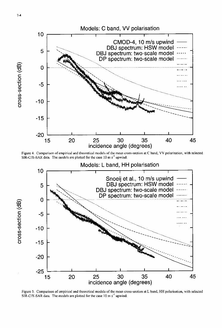
7-4
Models: C band, VV polarisation
n m U W
S 0 0 a>
.- c,
CT, ci, v)
0 2
10
5
0
-5
-1 0
-1 5
-20 15
I I I I
....
I
CMOD-4, 10 m/s upwind - DBJ spectrum: HSW model
DBJ spectrum: two-scale model - - - - - .
....
_ _ _ _ _.
_ _ _ _ - -
20 25 30 35 incidence angle (degrees)
40 45
Figure 4. Comparison of empirical and theoretical models of the mean cross-section at C band, VV polarisation, with selected SIR-C/X-SAR data. The models are plotted for the case 10 m f' upwind.
n m U W
10
5
0
-5
-1 0
-1 5
-20
-25 15
Models: L band, HH polarisation I 1 I I I
Snoeij et al., 10 m/s upwind - DBJ spectrum: HSW model
DBJ spectrum: two-scale model - - - - - .
- .-.- _ _ _ - -. _ _ _ _ _ - _ _ - _ _ _
20 25 30 35 incidence angle (degrees)
40 45
Figure 5. Comparison of empirical and theoretical models of the mean cross-section at L band, HH polarisation, with selected SIR-CIX-SAR data. The models are plotted for the case 10 m s-' upwind.
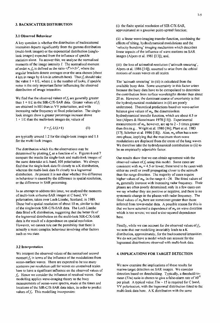
3. BACKSCATTER DISTRlBUTION (i) the finite spatial resolution of SIR-C/X-SAR, approximated as a gaussian point-spread function;
E
3.1 Observed Behaviour
A key question is whether the distribution of backscattered intensities departs significantly from the gamma distribution (multi-look images) or the exponential distribution (single- look images) expected from the influence of speckle statistics alone. To answer this, we analyse the normalised moments of the image intensity I. The normalised moment of order n,J, is defined as the ratio <fl>/<l>'', where the angular brackets denote averages over the area chosen (about 4 km in range by 6 km in azimuth here). Thusf, should take the value 1 + l / L , where L is the number of looks, if speckle noise is the only important factor influencing the observed distribution of image intensities.
We find that the observed values off, are generally greater than 1 4- 1/L in the SIR-C/X-SAR data. Greater values off, are obtained in HH than in VV polarisation, and with increasing radar frequency at fixed polarisation. The single- look images show a greater percentage increase above 1 + 1/L than the multi-look images do; values of
Y =f, L/ (L+I )
are typically around 1.2 for the single-look images and 1.1 for the multi-look images.
The distribution which fits the observations may be determined by plottingj;, as a function of n. Figures 6 and 7 compare the results for single-look and multi-look images of the same data-take at L band, HH polarisation. We always find that the single-look data fit closely to a K distribution, whereas the multi-look data fit closely to a lognormal distribution. At present it is not clear whether this difference in behaviour is caused by the difference in spatial resolution, or the difference in SAR processing.
In an attempt to address this issue, we analysed the moments of multi-look airborne-SAR images at C band, VV polarisation, taken over Loch Linnhe, Scotland, in 1989. These had a spatial resolution of about 10 m, similar to that of the single-look SIR-C/X-SAR data. The Loch Linnhe data fitted a K distribution, suggesting that the better fit of the lognormal distribution on the multi-look SIR-C/X-SAR data is the result of a dependence on spatial resolution. However, we cannot rule out the possibility that there is actually a more complex behaviour involving other factors such as sea state.
3.2 Interpretation
We interpret the observed values of the normalised second momentf, in terms of the influence of the modulations from ocean-surface waves. There are expected to be too many scatterers per resolution cell for waves on unresolved scales here to have a significant influence on the observed values of f,. Hence we consider the influence of resolved waves. Our modelling applies wave-imaging theory to the buoy measurements of ocean-wave spectra, made at the times and locations of the SIR-C/X-SAR data takes, in order to predict values off,. This modelling incorporates:
(ii) a linear wave-imaging transfer function, combining the effects of tilting, hydrodynamical modulations and the, 'velocity bunching' imaging mechanism which describes linear aspects of the influence of wave motions on SAR images (Alpers et al. 198 1 [ 131); and,
(iii) the loss of azimuthal resolution ('azimuth smearing', Alpers et al. 1986 [ 14]), assumed to arise from the orbital motions of ocean waves on all scales.
The 'azimuth smearing' in (iii) is calculated from the available buoy data. Some uncertainty in this factor arises because the buoy data have to be extrapolated to determine the contribution from surface wavelengths shorter than about 2 0 m. However, the dominant source of uncertainty is that the hydrodynamical modulations in (ii) are poorly understood. Theoretical predictions based on wave-action balance give values of mh, the dimensionless hydrodynamical transfer function, which are about 4.5 or less (Alpers & Hasselmann 1978 [ 151). Experimental measurements of mh, however, are up to 2 - 3 times greater than this (e.g. . Wright et al. 1980 [16]; Plant et al. 1983 [ 171; Schroter et al. 1986 [ 181). Also, mh often has a non- zero phase, implying that the maximum short-wave modulations are displaced from the crests of the long waves. We therefore take the hydrodynamical contribution to (ii) to be an empirically adjustable factor.
Our results show that we can obtain agreement with the observed values off , using this model. Some cases are consistent with mh = 4.5 or lower; these tend to be cases with either no swell or swell propagating closer to the azimuth than the range direction. The majority of cases require higher values of mh, in the range 6 - 24. The fitted values of mh generally increase with increasing radar frequency. Their phases are often poorly determined; only in a few cases can we say whether they are positive or negative, and there is no systematic change in the phases with radar frequency. The fitted values of mh here are sometimes greater than those inferred from tower-radar data. A possible reason for this is that we have assumed a dependence of mh on wave direction which is too severe; we used a sine-squared dependence here.
Finally, while we can account for the observed values off,, we note that our modelling invariably leads to a K distribution, approximately, for the backscattered intensities. We do not yet have a model which can account for the lognormal distributions observed with multi-look data.
4. IMPLICATIONS FOR TARGET DETECTION
We now examine the implications of these results for marine-target detection on SAR images. We consider detection based on thresholding. Typically, a threshold-to- mean (T/m) ratio is chosen to give a false-alarm rate of 10' per pixel. A typical value T/m - 15 is required for C band, VV polarisation, with the lognormal distribution fitted to the multi-look data here. A K distribution with the same
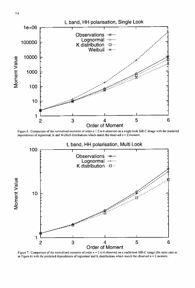
7-6
Q) 3 - 9 E f
c, c
L band, HH polarisation, Single Look 1 e+06
Observations + Lognormal -+--
K distribution a-- 100000
10000 Wei bu I I ...x .....
1000
100
10
1 2 3 4 5 6
Order of Moment Figure 6 . Comparison of the normalised moments of order n = 2 to 6 observed on a single-look SIR-C image with the predicted dependences of lognormal, K and Weibull distributions which match the observed n = 2 moment.
L band, HH polarisation, Multi Look 100
K distribution - 0 - -
10
1 2 3 4 5 6
Order of Moment Figure 7. Comparison of the normalised moments of order n = 2 to 6 observed on a multi-look SIR-C image (the same case as in Figure 6 ) with the predicted dependences of lognormal and K distributions which match the observed n = 2 moment.
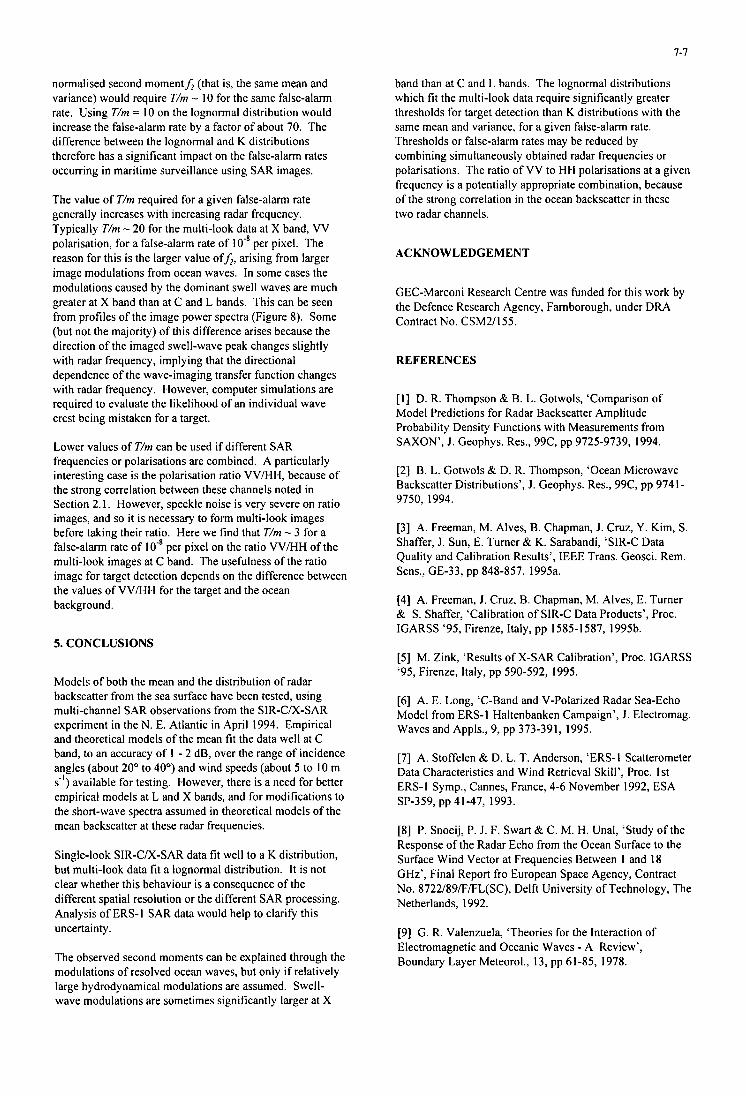
1-1
normalised second momentf, (that is, the same mean and variance) would require T/m - I O for the same false-alarm rate. Using T/m = I O on the lognormal distribution would increase the false-alarm rate by a factor of about 70. The difference between the lognormal and K distributions therefore has a significant impact on the false-alarm rates occurring in maritime surveillance using SAR images.
The value of T/m required for a given false-alarm rate generally increases with increasing radar frequency. Typically T/m - 20 for the multi-look data at X band, VV polarisation, for a false-alarm rate of IO-' per pixel. The reason for this is the larger value off,, arising from larger image modulations from ocean waves. In some cases the modulations caused by the dominant swell waves are much greater at X band than at C and L bands. This can be seen from profiles of the image power spectra (Figure 8). Some (but not the majority) of this difference arises because the direction of the imaged swell-wave peak changes slightly with radar frequency, implying that the directional dependence of the wave-imaging transfer function changes with radar frequency. However, computer simulations are required to evaluate the likelihood of an individual wave crest being mistaken for a target.
Lower values of T/m can be used if different SAR frequencies or polarisations are combined. A particularly interesting case is the polarisation ratio VV/", because of the strong correlation between these channels noted in Section 2. I . However, speckle noise is very severe on ratio images, and so it is necessary to form multi-look images before taking their ratio. Here we find that T/m - 3 for a false-alarm rate of IO' per pixel on the ratio VV/" of the multi-look images at C band. The usefulness of the ratio image for target detection depends on the difference between the values of VV/" for the target and the ocean background.
5. CONCLUSIONS
Models of both the mean and the distribution of radar backscatter from the sea surface have been tested, using multi-channel SAR observations from the SIR-C/X-SAR experiment in the N. E. Atlantic in April 1994. Empirical and theoretical models of the mean fit the data well at C band, to an accuracy of 1 - 2 dB, over the range of incidence angles (about 20" to 40") and wind speeds (about 5 to 10 m s-') available for testing. However, there is a need for better empirical models at L and X bands, and for modifications to the short-wave spectra assumed in theoretical models of the mean backscatter at these radar frequencies.
Single-look SIR-C/X-SAR data fit well to a K distribution, but multi-look data fit a lognormal distribution. It is not clear whether this behaviour is a consequence of the different spatial resolution or the different SAR processing. Analysis of ERS-I SAR data would help to clarify this uncertainty.
The observed second moments can be explained through the modulations of resolved ocean waves, but only if relatively large hydrodynamical modulations are assumed. Swell- wave modulations are sometimes significantly larger at X
band than at C and L bands. The lognormal distributions which fit the multi-look data require significantly greater thresholds for target detection than K distributions with the same mean and variance, for a given false-alarm rate. Thresholds or false-alarm rates may be reduced by combining simultaneously obtained radar frequencies or polarisations. The ratio of VV to HH polarisations at a given frequency is a potentially appropriate combination, because of the strong correlation in the ocean backscatter in these two radar channels.
ACKNOWLEDGEMENT
GEC-Marconi Research Centre was funded for this work by the Defence Research Agency, Farnborough, under DRA Contract No. CSM2/155.
REFERENCES
[ I ] D. R. Thompson & B. L. Gotwols, 'Comparison of Model Predictions for Radar Backscatter Amplitude Probability Density Functions with Measurements from SAXON', J. Geophys. Res., 99C, pp 9725-9739, 1994.
[2] B. L. Gotwols & D. R. Thompson, 'Ocean Microwave Backscatter Distributions', J . Geophys. Res., 99C, pp 9741- 9750, 1994.
[3] A. Freeman, M. Alves, B. Chapman, J. Cruz, Y. Kim, S. Shaffer, J. Sun, E. Turner & K. Sarabandi, 'SIR-C Data Quality and Calibration Results', IEEE Trans. Geosci. Rem. Sens., GE-33, pp 848-857, 1995a.
[4] A. Freeman, J. Cruz, B. Chapman, M. Alves, E. Turner & S. Shaffer, 'Calibration of SIR-C Data Products', Proc. IGARSS '95, Firenze, Italy, pp 1585-1587, 1995b.
[5] M. Zink, 'Results of X-SAR Calibration', Proc. IGARSS '95, Firenze, Italy, pp 590-592, 1995.
[6] A. E. Long, T-Band and V-Polarized Radar Sea-Echo Model from ERS-I Haltenbanken Campaign', J. Electromag. Waves and Appls., 9, pp 373-391, 1995.
[7] A. Stoffelen & D. L. T. Anderson, 'ERS-I Scatterometer Data Characteristics and Wind Retrieval Skill', Proc. 1st ERS-I Symp., Cannes, France, 4-6 November 1992, ESA SP-359, pp 41-47, 1993.
[8] P. Snoeij, P. J. F. Swart & C. M. H. Unal, 'Study of the Response of the Radar Echo from the Ocean Surface to the Surface Wind Vector at Frequencies Between 1 and 18 GHz', Final Report fro European Space Agency, Contract No. 8722/89/F/FL(SC), Delft University of Technology, The Netherlands, 1992.
[9] G. R. Valenzuela, 'Theories for the Interaction of Electromagnetic and Oceanic Waves - A Review', Boundary Layer Meteorol., 13, pp 61-85, 1978.
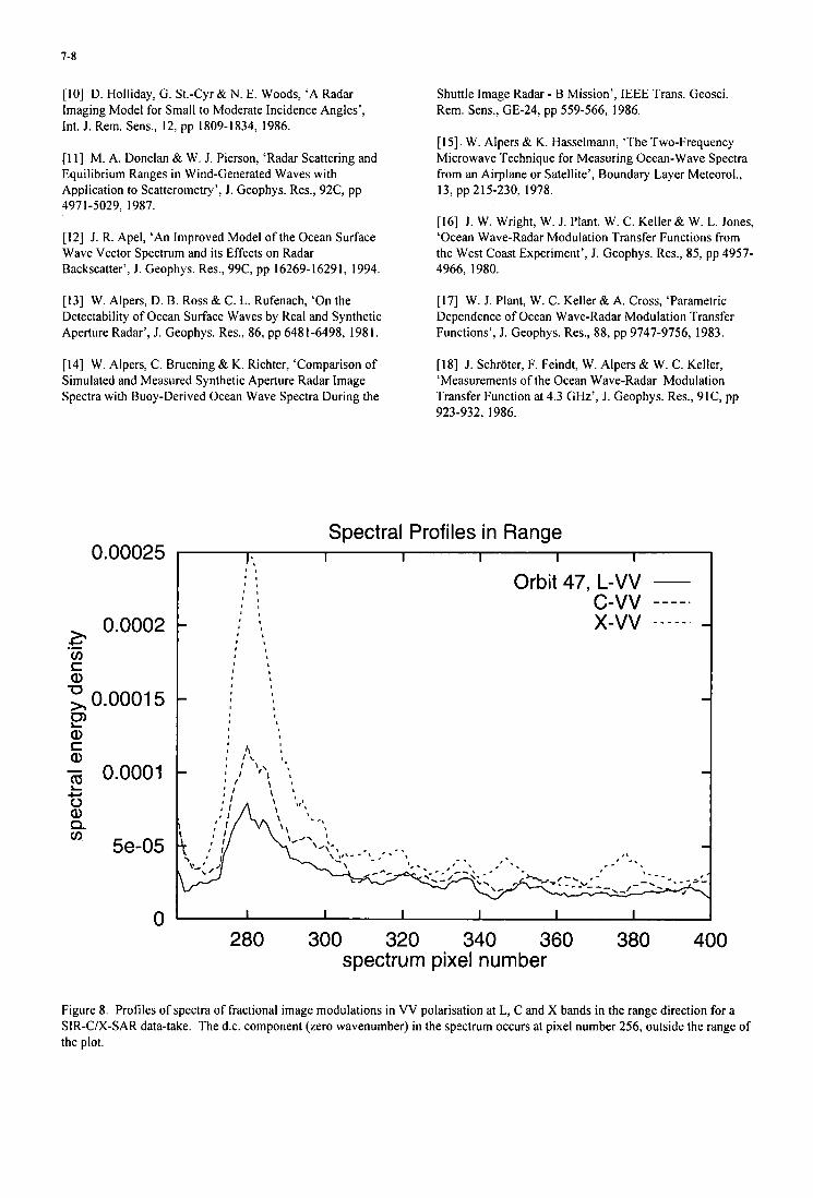
7-8
[ I O ] D. Holliday, G. St.-Cyr & N. E. Woods, ‘A Radar Imaging Model for Small to Moderate Incidence Angles’, Int. J. Rem. Sens., 12, pp 1809-1834, 1986.
[I I ] M. A. Donelan & W. J . Pierson, ‘Radar Scattering and Equilibrium Ranges in Wind-Generated Waves with Application to Scatterometry ’, J. Geophys. Res., 92C, pp 4971-5029, 1987.
[ 121 J. R. Apel, ‘An Improved Model of the Ocean Surface Wave Vector Spectrum and its Effects on Radar Backscatter’, J . Geophys. Res., 99C, pp 16269-16291, 1994.
[I31 W. Alpers, D. B. Ross & C. L. Rufenach, ‘On the Detectability of Ocean Surface Waves by Real and Synthetic Aperture Radar’, J. Geophys. Res., 86, pp 648 1-6498, 198 1.
[I41 W. Alpers, C. Bruening & K. Richter, ‘Comparison of Simulated and Measured Synthetic Aperture Radar Image Spectra with Buoy-Derived Ocean Wave Spectra During the
0.00025
0.0002 .- 3- U) r a,
0.0001 5 U
P
- 0.0001 2
Q) c Q)
CI 0 a, Q U) 5e-05
0
Shuttle Image Radar - B Mission’, IEEE Trans. Geosci. Rem. Sens., GE-24, pp 559-566, 1986.
[ 151. W. Alpers & K. Hasselmann, ‘The Two-Frequency Microwave Technique for Measuring Ocean-Wave Spectra from an Airplane or Satellite’, Boundary Layer Meteorol., 13, pp 215-230, 1978.
[I61 J. W. Wright, W. J . Plant, W. C. Keller& W. L. Jones, ‘Ocean Wave-Radar Modulation Transfer Functions from the West Coast Experiment’, J. Geophys. Res., 85, pp 4957- 4966, 1980.
[I71 W. J. Plant, W. C. Keller & A. Cross, ’Parametric Dependence of Ocean Wave-Radar Modulation Transfer Functions’, J. Geophys. Res., 88, pp 9747-9756, 1983.
[ 181 J. Schroter, F. Feindt, W. Alpers & W. C. Keller, ‘Measurements of the Ocean Wave-Radar Modulation Transfer Function at 4.3 GHz’, J. Geophys. Res., 91C, pp 923-932, 1986.
Spectral Profiles in Range I’. I I I I I
280 300 320 340 360 380 400 spectrum pixel number
Figure 8. Profiles of spectra of fractional image modulations in VV polarisation at L, C and X bands in the range direction for a SIR-C/X-SAR data-take. The d.c. component (zero wavenumber) in the spectrum occurs at pixel number 256, outside the range of the plot.
8- 1
Possible Features of NATO Communications Satellite Gap Filler
Mr. P. Ricci and Mr. A. Franzosi ALENIA Spazio via Saccomuro, 24
00131 ROMA l T K Y
1. Introduction.
NATO strategy is changed and emphasis is now on Multinational Groups, Mobile and Rapid Reaction Forces which are easily deployable in the crisis area and capable of rapid responses. In the new political scenarios, satellites are the only assets which can provide the timely and reliable communications required to exercise the command and control of deployed forces. It is also clear that space is the fourth component of a military operation and the role of communication satellites is of crucial importance for peace keeping, peace making operations and for the conduct of conflicts in areas where ground communications facilities can not be easily set up or are not any longer available. NATO communications satellites are expected to terminate their operational life around 2002/2003
and a decision is to be made on how to procure the communications capacity required to support NATO operations after that period. Based on the above consideration, we will examine a range of solutions to overcome the possible lack of NATO MILSATCOM assets in the next few years.. In addition the possible solutions will be based on the criteria of using entire units and packages available off the shelf as many as possible for the construction of the NATO Gap Filler Satellite.
2. NATO Information Exchange Requirements.(TERs)
The NATO Command, Control and Communications Architecture is divided into the Special Purpose and the General Purpose Segments. They can be defined as follows:
- Special Purpose Segment: a specialized communications component, which meet the requirement for highly survivable communications. - General Purpose Segment : a mixture of NATO, national and commercial assets supporting mobile and static communications .
NATO IV A and B Communications Satellites provide their contribution to both components. The NATO SATCOM Post 2000 working party identified as total satellite communications a IERs of about 130 Mbps soon after year 2000.
Paper presented at the AGARD MSP Sth Symposium on “Space Systems as Contributors to the NATO Defence Mission”, held in Cannes, France, 3-6 June 1996, and published in CP-580.
8-2
Notwithstanding the lack of a full agreement by the nations, we can consider that figure realistic enough considering the expected implementation of new wideband services.That figure represents in fact an approximated increase of one order of magnitude of the satellite communication services loaded on the NATO IV A and B in 1993 . The document indicates moreover that under stressed conditions around 10 Mbps are the Special Purpose Segment IERs on Communication Satellites. If dramatic changes take place in the satellite communications capacity procurement philosophy, changes however unlikely to occur as they will bring the total reliance on some major NATO nations or the total dependance on commercial satellites, the immediate consequence will be the unhlfillment of at least of a portion of the NATO communications requirements. However as rule of thumb, we can suppose that half of the traffic, roughly the traffic generated by static terminals, could be accomodated on Commercial Satellites or routed via terrestrial networks.To clear the remaining portion of traffic, which includes the stressed traffic and traffic generated by mobile users, a Military Satcom System is needed. NATO can not therefore renounce to a military communications satellite which could be moreover designed to provide: - multiple beams, which ensure a flexible coverage and permit the use of disavantaged terminals. - direct connections of small terminals ,which allow the timely set up of tactical nets - resistance to up links jamming : a typical requirement of deployed forces. - communications protection from the effects of nuclear explosions.
3. Description of the possible NATO Gap Filler Satellite.
A. General.
The NATO Gap Filler Communication satellite should provide coverage of Europe, North and Central Africa, Middle East and Western Asia to cope with NATO's new roles represented by " out of area " operations. The frequency bands of operation should be selected among the UHF, SHF and EHF . The UHF and SHF bands provide the benefit of ensuring backwards compatibility with existing ground terminals.The SHF band has, in addition, the capability of routing a portion of the stressed SPS traffic. Finally the EHF processed band could be used for the transmission of the stressed traffic, while a transparent portion of it, for transmissions at high data rates. As the EHF terminals will be largely introduced into service by mobile forces, the EHF band could be used for their direct connections. NATO Gap Filler Satellite should in fact be designed to provide support to mobile operations which require primarily the use of manportable and other small terminals . For that purpose adequate EIRP should be radiated at UHF and on all beams generated at SHF and EHF .
8-3
Four possible configurations of the NATO Gap Filler Satellite will be considered. (1) UHF. SHF and EHF configuration
(a) Introduction
A NATO Satellite Gap Filler based on a UHF, SHF and EHF payload will be able to route all NATO traffic in the coverage area provided that a relevant portion of the traffic of the Special Purpose Segment would be cleared through the EHF payload.
(b) Payload description:
To be able to clear all NATO traffic the payload should be featured as follows:
(( 1)) UHF Payload
The UHF package will be basically applied to continue the use of the large amount of small UHF terminals presently in the NATO inventory (around 200 terminals), most of them assigned to Rapid Reaction Forces. 20 UHF channels each with a 25 KHz bandwidth will be required to establish all possible connections. To increase the number of partecipants to the networks, TDMA/DAMA access could be used on selected nets. Global coverage within the field of view of the satellite will provide every terminal, wherever deployed, with the possibility of communicating. Multicarrier linearized solid state power amplifiers, rated at 60 w linear power, will amplifL the transmit carriers. Using TDMADAMA systems, the UHF package will be able to carry between 0,25 to 0.5 Mbps, meeting the majority of tactical communications requirements.
((2)) SHF Payload
The SHF payload will meet the backwards compatibility and mobile users connectivity requirements. A payload configured in 4 transparent channels, each driving a solid state power amplifier (SSPA)will be sufficient to cope with the expected traffic on that band. In fact a first repeater will be required to route traffic for mobile forces, a second repeater will be dedicated to the transmission of TRANSEC protected traffic, while the two remaining repeaters will be used to meet other communications requirements. All the repeaters will be connected to multibeam and to earth coverage antennas and to a SHFEHF mechanical spot antenna.To keep at minimum the modifications of the existing TTC control stations, the TTC uplink could be operated at SHF . All the communication services will be provided through transparent satellite channels.
8-4
As the up link TTC Signals will be encrypted and spread, one channel on board processed will be required to provide highly protected commands to the satellite.The 4 transparent repeaters, through a switching matrix, will have the possibility of connecting traffic received from all beams and the mechanical spot antenna to a global coverage and viceversa.The 4 SHF repeaters are supposed to be capable of carrying at least 20 Mbps (5 Mbps on the repeater for Marittime Forces, 0.5 Mbps on the repeater dedicated to TRANSEC traffic and the remaing 14.5 Mbps on the two left repeaters).
((3)) EHF PAYLOAD
The use of regenerative EHF channels will offer the possibility of transmitting data rates from 2.4 Kbps up to 2 Mbps with an adequate level of robustness against exploitation and jamming, implementing the waveforms of STANAG 4522 "Digital Interoperability between Medium Data Rate ( MDR) EHF SATCOM terminals". The EHF antennas will support global, multibeam and spot coverage. The output of the global coverage, the spot and multibeam antennas will be connected to 10 MDR channels each of 62.5 MHz bandwidth . The output of those channels will be dehopped and down converted to an intermediate frequency. .The signals received will be,then, demodulated by the Signal Processor and routed to destination via a Message Processor . Through the on board Access Control Messages system, the field units may request the Control Station the implementation of some communications services such as moving the spot beam to an appropriate area, establishing a new network, joining an existing net and The above mentioned communication services will be performed in near real time which is one of the basic communication requirements of modern mobile forces. To the left portion of the EHF band, 4 transparent channels of 62.5 Mhz bandwidth will be applied. The 4 transparent channels, which could be cross strapped to the SHF payload,will be able to carry traffic at data rates higher than the 2 Mbps allowed on the regenerative EHF MDR channels. A Master Clock Generator will be applied to the satellite to provide time reference to all digital equipment. In addition, the Master Clock Generator will provide time reference to the Ground Network, using beacon emissions at EHF and SHF. The time transmitted will constitute the reference on which all ground terminals will be synchronized.
making a point to point call.
(c) Satellite Antennas
The antennas suite will be composed of antennas capable of ensuring the coverage with the generation of the spots required..
8-5
(( 1)) UHF Antennas.
One receive and one transmitting patch antenna with dimensions of 6.5 square meters each will ensure the earth coverage with the appropriate gain to allow communications f r o d t o all UHF terminals.
((2)) SHF Antennas.
The SHF multibeam and the mechanical steerable spot up link antenna will be associated to the nulling system designed for jammer location and nulls generation . The reconfiguration of the antennas, with the steering in the required directions of the multibeam and of the mechanical spot antenna will happen after a few seconds that ground commands have been received. The multibeam antenna diameter will be of 1.2 mt.,which is a dimension suitable to generate at the earth surface multiple beams of 1500 kin. of diameter. The composite beams can therefore ensure a wide coverage area, the SHF down link antenna with diameter of 1 mt. will generate a corrisponding wide area of larger dimension. A 0.8 mt. diameter mechanical steerable spot beam antenna will also provide up/down link coverage in both the SHF and EHF bands for communications and the jammer location and nulls generation service. Two earth coverage horn antennas will complete the SHF antenna suite, one will be used for the up link signal reception while the second for the down link transmission.
((3)) EHF Antennas.
The EHF up/down link multibeam antenna of about 0.4 mt. diameter, with a receive beam of about 800 Km. of diameter at the earth surface, will have nulling and reconfiguration capability over the Central Europe, Middle East and Western Asia Area. The nulling system and the antenna configuration will be controlled from the ground, as in the case of the SHF antenna. The mentioned SHFEHF mechanical steerable spot antenna and two global coverage horns will complete the EHF antenna suite.
(d) Satellite Pavload mass and power budget.
The payload mass estimate is around 400 Kg. for a total satellite dry mass of about 200 Kg. The launch mass is in the range of 2500 Kg. for a mission life of about 10 years with f i l l orbital control . The total power requirement is in the range of 2200 to 2500 W.
8-6
The satellite main characteristics are : 0
0
0
0
0
0
0
0
Orbit : Geosyncronous Stabilization: 3 axis Attitute Control: Sun and Earth Sensor Comms.Payload : UHF,SHF and EHF bands Payload mass : 400 Kg. Satellite dry mass : 1200 Kg. Launch mass : 2500 Kg. Power : 2200-2500 W
0 Propulsion : Liquid bipropellant 0
0 TTC : SHF band. EHF could be used also Operational life : 10 years.
A Satellite possible layout is at fig. 1, while its simplified payload block diagram is at fig.2
(e) Considerations.
The introduction of wideband communication services will bring a growth of the data rates to be transmitted. . Such medium size multifrequency satellite would be able to meet all NATO E R s and future traffic expansion.It will constitute probably the precursor or the first in orbit of a new generation of a constellation of satellites.
(2) SHF + UHF Configuration
In case the EHF payload is not selected for the Satcom Gap Filler architecture, the satellite configuration will be changed in a way that inass and power coinsumption will not be reduced. In fact the number of SHF repeaters would be increased from 4 to 6 together with the application of an additional European Coverage Beam antenna. The mass would moreover increase as some repeater channels would require higher power achievable with the substitution of SSPAs with TWTAs to support mobile and disavantaged terminals. As a matter of fact we assume that this solution would not be considered as it appears unsuitable to meet NATO IERs particularly under stressed conditions. In addition, that solution will augment the need of using commercial satellites to route static terminals traffic.
8-7 I
(3) SHF + EHF Configuration
This solution seems very attractive because the elimination of the UHF payload permits a large reduction of satellite mass and power comsumption, also facilitating the thermal control aspects . With that architecture the satellite dry mass would be as low as about 900 Kg and the overall power requirement about 1700 w. The disavantage of that architecture is that NATO UHF backwards requirements are to be met with high cost leased UHF channels on which no or limited control could be exercised. The SHF + EHF configuration appears, however, suitable to route all NATO IERs.
(4) SHF only Configuration
From the mass and power requirements point of view this solution is equivalent to the SHF + EHF architecture .Different simplified solutions could be made available. As an example the "SHF only solution "may be conceived provided with a SHF multibeam, a mechanical steerable spot antenna and global horns plus SSPAs to reduce the payload dry mass. This type of satellite, alone or better in constellation of two, would have the advantage of minimum cost although with the probable limitation of being unable to route all stressed traffic. It should be considered only if the requirement to keep as low as possible the financial cost of the Gap Filler Satellite is prevailing on achieving the capability to clear all NATO IERs.
4. Conclusions.
Military Communication Satellites are the unique, strategic assets able to provide the necessary communications capability for exercising the Coininand and Control of mobile and deployed forces and for ensuring the special purpose segment communications during peacetime operation and in times of crisis. According to our view, NATO can not renounce to military Satellites and preference should be given to the UHF, SHF and EHF configuration. That configuration could be used as a bridghead towards the future, as during its operational life it will be able to meet the identified IERs and , at the same time, to cope with possible further traffic expansion. In fact: - the use of the UHF band, presently made primarily by ships, submarines and manpack terminals, will be in the next few years increased, as new airborne terminals will become operational on the Alliance aircraft.
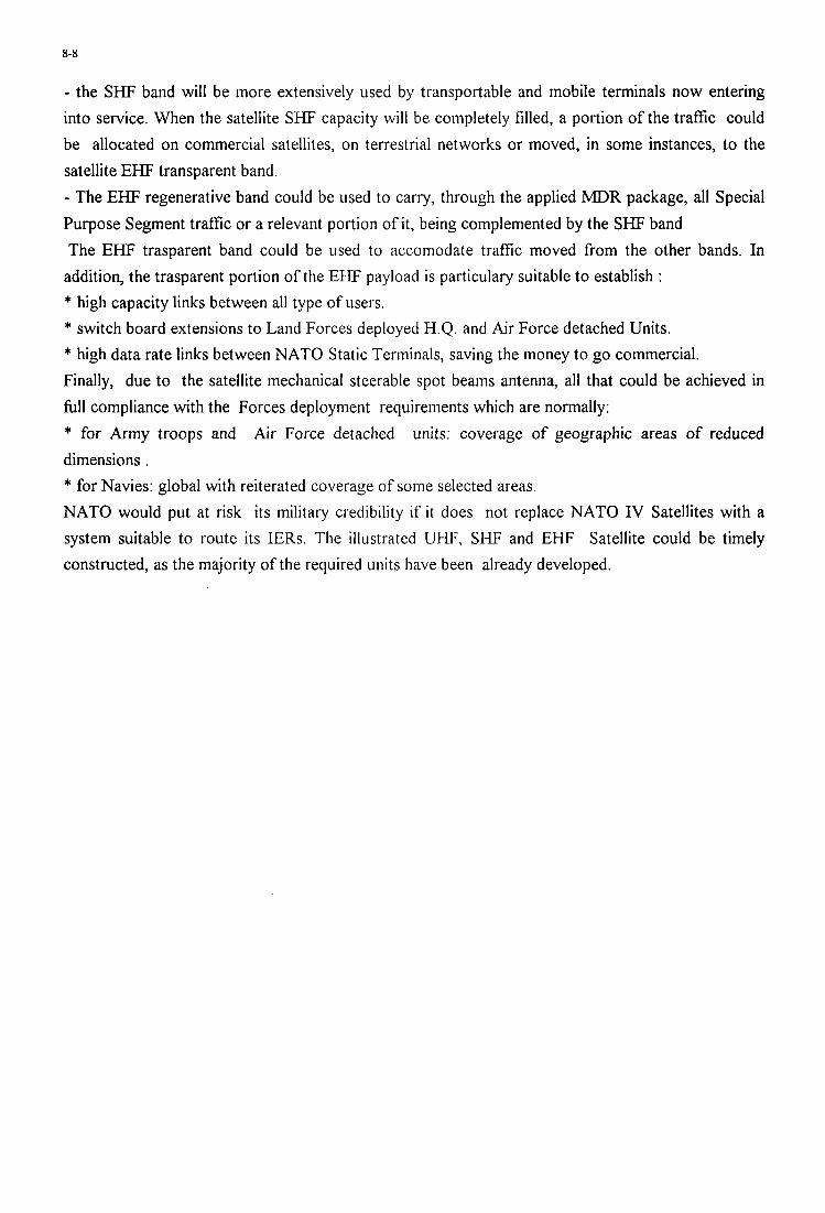
8-8
- the SHF band will be more extensively used by transportable and mobile terminals now entering into service. When the satellite SHF capacity will be completely filled, a portion of the traffic could be allocated on commercial satellites, on terrestrial networks or moved, in some instances, to the satellite EHF transparent band. - The EHF regenerative band could be used to carry, through the applied MDR package, all Special Purpose Segment traffic or a relevant portion of it, being complemented by the SHF band The EHF trasparent band could be used to accomodate traffic moved from the other bands. In
addition, the trasparent portion of the EHF payload is particulary suitable to establish : * high capacity links between all type of users. * switch board extensions to Land Forces deployed H.Q. and Air Force detached Units. * high data rate links between NATO Static Terminals, saving the money to go commercial. Finally, due to the satellite mechanical steerable spot beams antenna, all that could be achieved in full compliance with the Forces deployment requirements which are normally: * for Army troops and Air Force detached units: coverage of geographic areas of reduced dimensions . * for Navies: global with reiterated coverage of some selected areas. NATO would put at risk its military credibility if it does not replace NATO IV Satellites with a system suitable to route its IERs. The illustrated UHF, SHF and EHF Satellite could be timely constructed, as the majority of the required units have been already developed.
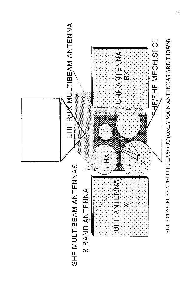
8-9 I
I- n
a m c/)
E 3 0 z w d 6 < z z w t- z 6 z
t: + 0 t- 3 0 >1 6 Ll w t-
Ll w t- 6 w Ll m m m 0 k
m
m
7
v
=i
m
Y
.. l+
6 E:
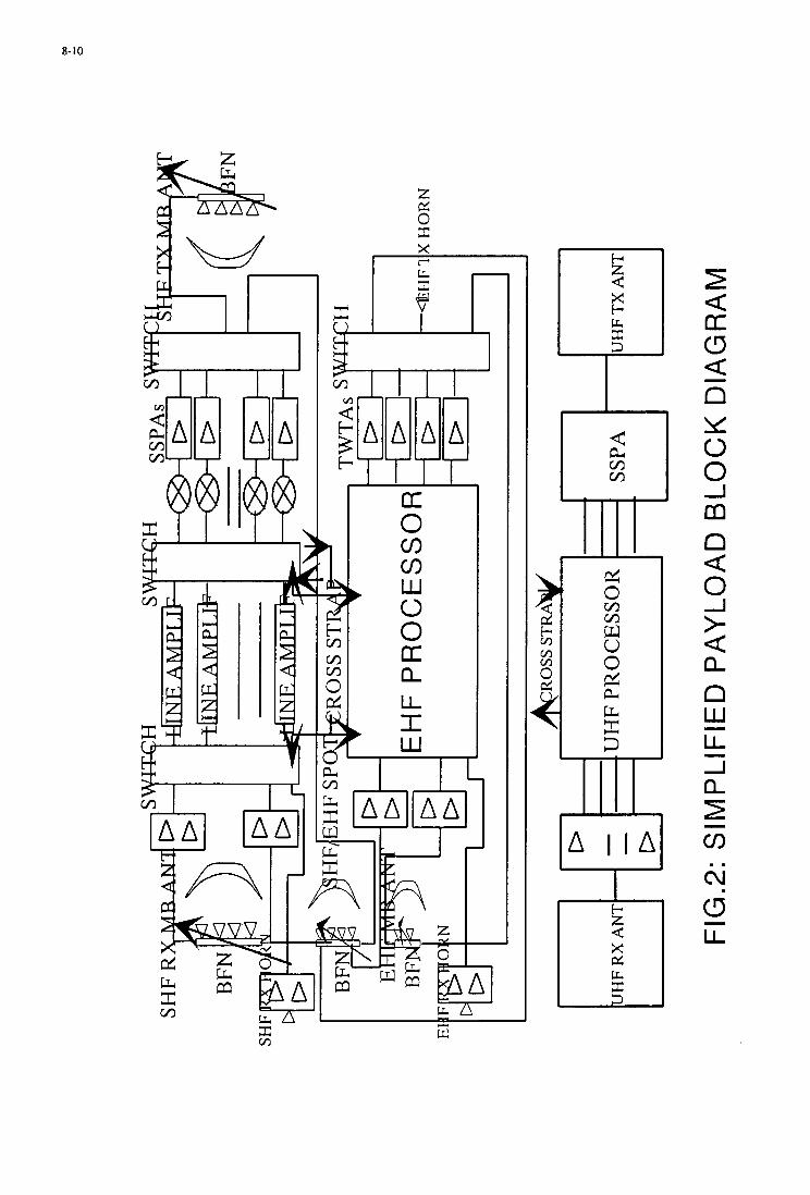
8-10
m
M
I
I U 1 I o I
c/)
W 0 0 kt U [1.
LL I W
” A I I
v 3
Lt
13-1
RESULTATS EXPERIMENTAUX D’ANTIBROUILLAGE D’UNE ANTENNE EMBARQUEE
DE TELECOMMUNICATION PAR SATELLITE
P.TUTARD/JP POUX
ZI Le Mont Jarret 76520 YMAREFRANCE
THOMSON-CSF AIRSYS
F. CROQ ALCATEL ESPACE 26 Ave J-F Champollion
31037 TOULOUSE CEDEX FRANCE
SOMMAIRE
I - Introduction
I1 - Hypotheses de travail
I11 - Objectifs du demonstrateur
IV - Rappel du principe de 1’OLS
V - Etude et tests d’un FAFR + OLS mixte
1) Description du demonstrateur 2) Caracterisation des performances 3) Deroulement des travaux 4) Methodologie des tests 5) Principaux rksultats obtenus a ce
jour
VI - Evolution du demonstrateur en 1996 - 1997
VI1 - RCferences
LISTE DES SYMBOLES
FAFR : Feed Array Focal Reflector
DRA : Direct Radiating Array
OLS : Opposition dans les Lobes Secondaires
CAN : Convertisseur Analogique/Numerique
RFP : Reseau Formateur de Pinceaux
CDMA : Code Division Multiple Access
FH : Frequency Hopping
Conops : Concept of operations
Paper presented at the AGARD MSP SIh Symposium on “Space Systems as Contributors to the NATO Defence Mission ”, held in Cannes, France, 3-6 June 1996, and published in CP-580.
13-2
I - Introduction
La prochaine generation de satellites de telecommunications militaires doit per- mettre une meilleure satisfaction des besoins operationnels en assurant la desserte de davantage de the8tres d’opkrations simultanes et un surcroft de protection contre le brouillage elec- tromagnetique (ref. 1).
Sous l’egide de la Delegation Gknerale de 1’Armement Alcatel Espace et THOMSON-CSF ont etudik et realise un demonstrateur d’antenne anti- brouillee pour la reception SHF a bord d’un satellite.
Cette antenne multifaisceaux active est associee a un antibrouillage auto- adaptatif utilisant une technique dite (( d’opposition dans les lobes secondai- res )) (OLS). L’analyse et la simulation de plusieurs solutions ont conduit au choix d’une antenne a reflecteur munie d’une retine active, associee a un trai- tement OLS. L’OLS elimine le brouillage des voies principales par la sommation ponderee, en analogique, de celles-ci avec des voies auxiliaires des- tinees a capter les brouilleurs. Le calcul de la ponderation adequate s’effectue en numerique.
L’antenne antibrouillee est donc consti- tuCe de deux fonctions principales : la fonction reception et la fonction annu- lation de brouilleurs.
La fonction de reception comprend :
- la reception des signaux par un en- semble reflecteur plus reseau de sour- ces actives,
- l’amplification faible bruit des signaux reps,
- la formation des faisceaux voies prin- cipales et voies auxiliaires par selec-
tion et sommation ponderee (phase et amplitude) des signaux captes sur chacune des sources.
L’annulation de brouilleurs comprend :
- la transposition en bande de base des voies de reception,
- la numkrisation des signaux et leur stockage,
- la configuration des voies auxiliaires en fonction de la direction d’arrivee des brouilleurs,
- le calcul des coefficients d’opposition et la mise en opposition analogique des voies auxiliaires sur les voies principales.
Le demonstrateur d’antenne anti- brouillee a ete realise et teste fin 95. Les mesures en champ lointain se pour- suivent aujourd’hui afin de caracteriser les performances d’ensemble face a une variete de scenaris operationnels : brouilleurs dkcoupes, brouilleurs loin- tains (en dehors du lobe principal de l’antenne) et brouilleurs proches (dans le lobe principal).
Le demonstrateur actuel effectue les calculs d’auto-adaptation des coeffi- cients d’antibrouillage en temps differ& Un calculateur temps reel sera associe au demonstrateur fin 96, afin de valider, courant 97, les performances dynami- ques du systeme d’antibrouillage avec des cadencements identiques a ceux de l’antenne operationnelle.
I1 - Hypotheses de travail
Les principales hypotheses prises en compte pour l’etude sont les suivantes :
13-3
-Bande de frkquence SHF : liaison montante a antibrouiller 7.9 a 8.4 Ghz,
- Antenne de reception operationnelle comportant 4 faisceaux directifs orien- tables avec la capacitk d’antibrouiller simultanement l’ensem ble des fais- ceaux face a des brouilleurs multiples,
- Pour assurer la continuite de service des systemes existants de la compo- sante sol actuelle, l’antenne doit etre compatible avec les signaux de type SYRACUSE 1 et 2 : CDMA, SS- FDMA et FDh4A ((civil ))
- Pour repondre aux fiturs besoins, elle devra etre compatible avec les signaux de type nouveau qui pourront etre in- troduits, notamment du saut de fre- quence de type STANAG 4376,
- Brouilleurs de tous types : a bruit, a raies (monoraie ou multiraies), conti- nus ou decoupes ...
I11 - Objectifs du ddmonstrateur
Du point de vue de l’antibrouillage, les points durs essentiels sont :
- la largeur de bande 7,9 - 8,4 Ghz sur laquelle l’antibrouillage doit Etre ef- fectif,
- la dynamique importante des signaux a traiter (cas des brouilleurs forts et moyens),
- le pouvoir de resolution important ne- cessaire pour lutter contre les brouilleurs proches, en bord de cou- verture.
- de dkmontrer la faisabiliti d’une antenne antibrouillke repondant aux exigences de performance exprimties dans les Conops,
- de conforter les specifications induites sur les sous-ensembles et ‘les compo- sants par les exigences d’ensemble,
- de valider et de mettre au point les algorithmies de mise en oeuvre de 1 ’ antibrouillage,
- de caracteriser et de maitriser l’en- semble des parametres dimensionnants du sous-systeme,
- de verifier les performances aux limi- tes (brouilleurs se rapprochant du bord de couverture, brouilleurs en limite de dynamique des chaines de reception.. .)
IV - Rappel du principe de I’OLS
On cherche par la methode OLS a re- duire au maximum la puissance de brouillage reque par une antenne direc- tive pointee dans une direction utile et attaquee par un ou plusieurs brouilleurs.
Pour cela, on utilise des voies auxiliai- res, auxquelles sont connectes des recep- teurs idealement identiques a celui de la voie principale.
Traditionnellement, la methode OLS est utilisie avec des voies auxiliaires for- mkes a partir de capteurs peu directifs (voire globaux). L’antibrouillage atteint alors sa perfor- mance maximale contre les brouilleurs penetrant le diagramme d’antenne par ses lobes secondaires (d’ou l’appellation OLS : opposition dans les lobes secon- daires).
Le but des travaux realises sur le de- monstrateur est :
13-4
La mime technique appliquee a des voies auxiliaires directives d’ouverture similaire a l’ouverture du faisceau principal permet d’obtenir des performacnes excel- lentes face a des brouilleurs situ& a proximite du bord de couverture (scenario operationnel le plus vrai- semblable sur les theatres deportes et contre lequel des antennes non antibrouillees sont particulierement vulnerables).
C’est donc par abus de langage que le nom de la technique <( OLS )) a kt6 conserve bien qu’elle permette une opposition sur des brouilleurs bien plus proches que dans les lo- bes secondaires, dans les flancs du lobe principal, dks le bord de cou- verture .
Les signaux requs sur les voies principales et auxiliaires etant constitues de combinaisons linkai- res differentes des mimes signaux (signal utile et brouilleurs), il est theoriquement possible de suppri- mer ceux issus des brouilleurs par adjonction au signal Vp de la voie principale d’une combinaison li- neaire adequate des signaux Vak des voies auxiliaires, a la condition que le nombre de voies auxiliaires soit superieur ou egal au nombre de brouilleurs.
Ainsi pour un OLS a n voies auxi- liaires, le signal anti-brouillk de la voie principale Vp’(t) est donnee
Par n
Vp‘(t) = Vp(t) - W k Vak(t) 7
k = l
ou Vp(t) est le signal de la voie principale (non anti-brouille), V d t ) le signal de la voie auxiliaire
k et W k le k-ieme coefficient du vecteur &opposition defini par w = Ta *- 1 C , (formule de Wiener) -
ou Ta est la matrice de covariance n x n des voies auxiliaires definie par
et oh _C est le vecteur d’inter-correlation defini par
* (L’etoile disigne la conjugaison com- plexe et 1’exposantT designe la trans- position matricielle).
En effet , on demontre que la puissance moyenne resultante E[Vpl(t)2] due aux brouilleurs est minimale si l’on prend
pour la valeur E = rc-l C,
V - Etude d’un FAFR + OLS mixte
1) Description du demonstrateur
Le demonstrateur d’antenne anti- brouillee en SHF est constitue de deux sous-ensembles.
Sous-ensemble antenne
I1 s’agit de l’aerien qui a kt6 CtudiC et mis au point par ALCATEL ESPACE .
La partie rayonnante est constituee d’un reflecteur de 2,2 m de diametre et d’un reseau de 100 sources positionnees sur une plaque support. Parmi ces
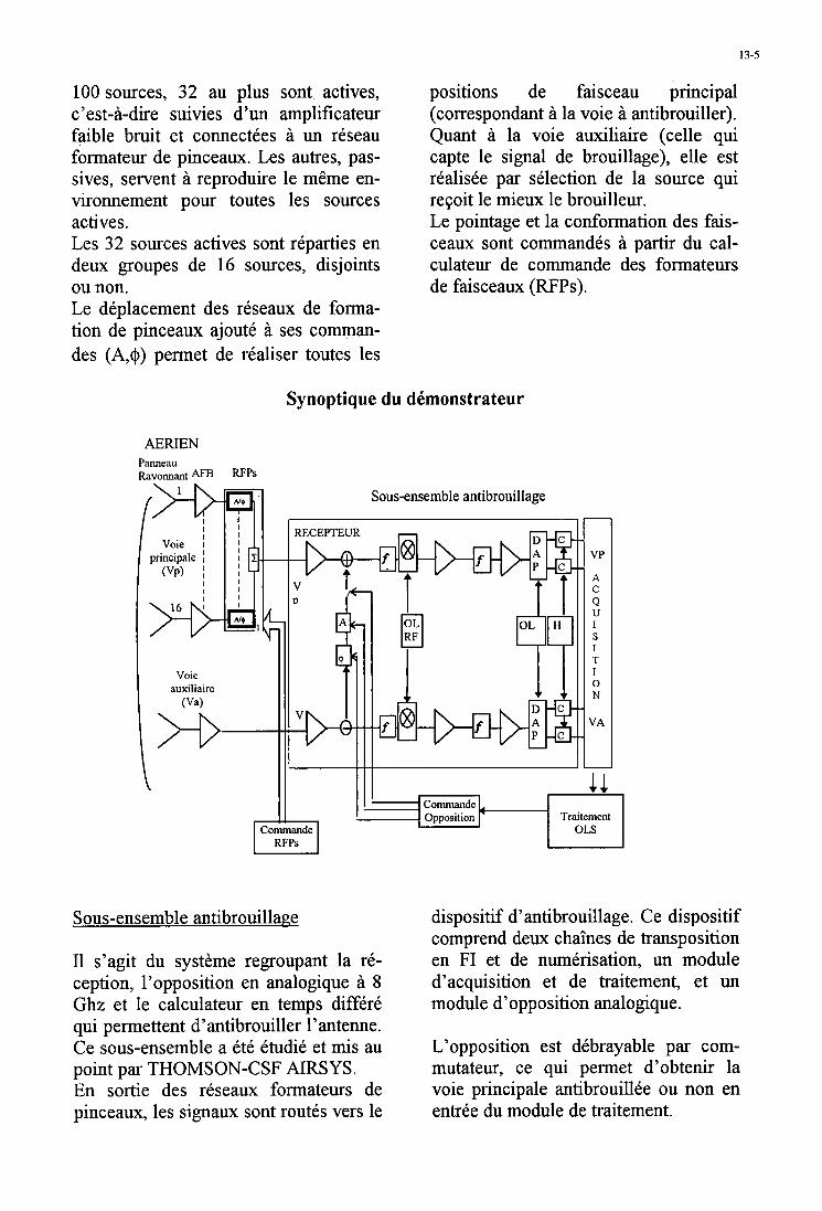
13-5
100 sources, 32 au plus sont actives, c’est-a-dire suivies d’un amplificateur faible bruit et connectkes a un reseau formateur de pinceaux. Les autres, pas- sives, servent a reproduire le meme en- vironnement pour toutes les sources actives. Les 32 sources actives sont reparties en deux groupes de 16 sources, disjoints
positions de faisceau principal (correspondant a la voie a antibrouiller). Quant a la voie auxiliaire (celle qui capte le signal de brouillage), elle est rCalisCe par selection de la source qui reFoit le mieux le brouilleur. Le pointage et la conformation des fais- ceaux sont commandds a partir du cal- culateur de commande des formateurs
~
ou non. de faisceaux (RFPs). Le dkplacement des reseaux de forma- tion de pinceaux ajoute a ses comman- des (A,@) permet de realiser toutes les
Synoptique du dkmonstrateur
AERIEN Panneau Ravonnant AFB RFps
T
0 N
Opposition Traitement Commande
RFPs
Sous-ensemble antibrouillage
I1 s’agit du systkme regroupant la re- ception, l’opposition en analogique a 8 Ghi: et le calculateur en temps differ6 qui permettent d’antibrouiller l’antenne. Ce sous-ensemble a et6 ktudie et m i s au
En sortie des reseaux formateurs de pinceaux, les signaux sont routes vers le
point par THOMSON-CSF AIRSYS.
dispositif d’antibrouillage. Ce dispositif comprend deux chakes de transposition en FI et de numerisation, un module d’acquisition et de traitement, et un module d’opposition analogique.
L’opposition est debrayable par com- mutateur, ce qui permet d’obtenir la voie principale antibrouillke ou non en entree du module de traitement.
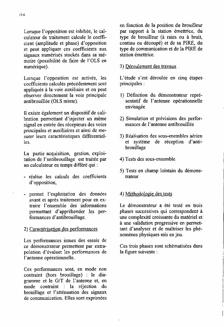
13-6
Lorsque l’opposition est inhibee, le cal- culateur de traitement calcule le coeffi- cient (amplitude et phase) d’opposition et peut appliquer ces coefficients aux signaux numerises stock& dans sa me- moire (possibilite de faire de I’OLS en nwnerique).
Lorsque l’opposition est activee, les coefficients calcules precedemment sont appliques a la voie auxiliaire et on peut observer directement la voie principale antibrouillee (OLS mixte).
I1 existe egalement un dispositif de cali- bration permettant d’injecter un meme signal en entree des recepteurs des voies principales et auxiliaires et ainsi de me- surer leurs caracteristiques differentiel- les.
La partie acquisition, gestion, exploi- tation de l’antibrouillage est traitee par un calculateur en temps differe qui :
- realise Ies calculs des coefficients d’opposition,
- permet I’exploitation des donnees avant et apres traitement pour en ex- traire l’ensemble des informations permettant d’apprehender les per- formances d’antibrouillage.
2) Caracterisation des performances
Les performances issues des essais de ce demonstrateur pennettent par extra- polation d’evaluer les performances de l’antenne operationnelle.
en fonction de la position du brouilleur par rapport a la station emettrice, du type de brouilleur (a raies ou a bruit, continu ou dkcoupk) et de sa PIRE, du type de communication et de la PIRE de station emettrice.
3) Dkroulement des travaux
L’etude s’est ddroulte en cinq etapes principales :
1) Definition du demonstrateur repre- sentatif de l’antenne operationnelle enwsagee
2) Simulation et previsions des perfor- mances de l’antenne antibrouillee
3) Realisation des sous-enembles akrien et systeme de reception d’anti- brouillage
4) Tests des sous-ensemble
5 ) Tests en champ lointain du demons- trateur
4) Mkthodoloaie des tests
Le demonstrateur a ete teste en trois phases successives qui correspondent a une complexit6 croissante du materiel et a une validation progressive en permet- tant d’analyser et de maltriser les phe- nomknes physiques mis en jeu.
Ces trois phases sont schematisees dans la figure suivante :
Ces performances sont, en mode non contraint (hors brouillage) : le dia- gramme et le G/T de l’antenne et, en mode contraint : la rejection du brouillage et l’attknuation des signaux de communication. Elles sont exprimees
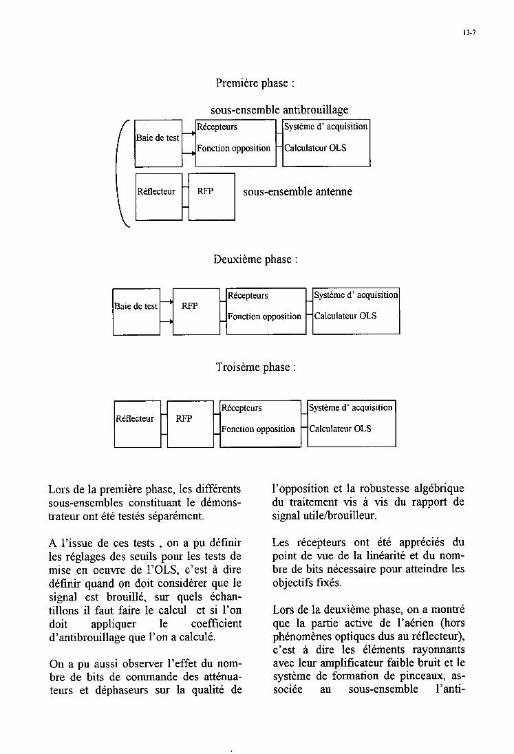
13-7
Premiere phase :
sous-ensemble antibrouillage
Baie de test
sous-ensemble antenne
Deuxieme phase :
Recepteurs
Fonction opposition Baie de test
Troiseme phase :
Recepteurs
Fonction opposition Reflecteur
Lors de la premiere phase, les differents sous-ensembles constituant le demons- trateur ont tte testes separement.
A l’issue de ces tests , on a pu definir les reglages des seuils pour les tests de mise en oeuvre de l’OLS, c’est a dire d e f ~ quand on doit considerer que le signal est brouille, sur quels echan- tillons il faut faire le calcul et si l’on doit appliquer le coefficient d’antibrouillage que l’on a calcule.
On a pu aussi observer l’effet du nom- bre de bits de comande des attenua- teurs et dephaseurs sur la qualite de
Systeme d’ acquisitioi
Calculateur OLS i I
Systeme d’ acquisition
Calculateur OLS i 1
l’opposition et la robustesse algkbrique du traitement vis a vis du rapport de signal utilehrouilleur.
Les recepteurs ont ete apprecies du point de vue de la linkarite et du nom- bre de bits necessaire pour atteindre les objectifs fixes.
Lors de la deuxieme phase, on a montrC que la partie active de l’atrien (hors phknomknes optiques dus au reflecteur), c’est a dire les elements rayonnants avec leur amplificateur faible bruit et le systkme de formation de pinceaux, as- sociee au sous-ensemble l’anti-
13-8
brouillage donne des resultats du meme ordre de grandeur que ceux obtenus lors de la premiere phase.
La troisieme phase permet de tester le demonstrateur complet en champ loin- tain et d’en apprecier ses performances en fonction de :
- la puissance de brouillage, -du rapport de puissance utile/
-de l’ecart angulaire entre l’utile et le
- du type de menace (bruit,monoraie, bi-
-du type de forme d’onde utile
- de la decoupe des brouilleurs.
brouilleur,
brouilleur,
raies ...)
(CDMA,FH.. .)
5 ) Principaux resultats obtenus a ce lour
Les tests effectues a ce jour, permettent de demontrer que les performances sont conformes et en certains points sup& rieures aux objectifs qui avaient kte fixes en debut d’etude, et ceci quelque soit le type de menace considere.
L’architecture retenue permet d’envisager un materiel opkrationnel realisable en technologie spatiale, a faible consommation et relativement simple de conception.
Les specifications induites sur les sous- ensembles antenne, reception, opposi- tion et sur les composants par les exi- gences d’ensemble ont ete confortees. Les parametres dimensionnants ont &e caracterises.
Dans toute technique d’opposition, il est imperatif de makiser les imperfec- tions differentielles des voies de recep- tion de l’antenne antibrouillee des ele- ments rayonnants de l’airien jusqu’au calculateur d’antibrouillage.
Le demonstrateur a permis de caracteri- ser les imperfections differentielles de l’ensemble des voies de reception, de verifier la faisabilite technologique des exigences exprimees et de valider l’algorithmie auto-adaptative de calcul des coefficients d’opposition.
La fonction opposition representant le coeur de 1’OLS mixte doit permettre d’appliquer au plus prks le coefficient d’opposition issu du calculateur d’antibrouillage. Pour cela, compte-tenu de la non linearite des composants, nous avons mis au point des techniques d’etalonnage des composants et des al- gorithmes de linearisation qui permet- tent d’appliquer les coefficients d’antibrouillage avec .une precision cor- respondant a un niveau de rejection meilleur de quelques dB que le niveau de rejection vise.
La calibration doit 2tre rafi-aichie pour chaque canal de travail (position de l’oscillateur local hyperfi-equence de reception), a chaque nouveau reglage de l’amplification de t2te et pour cer- tains ecarts de tempkrature a bord du satellite.
La fonction opposition analogique doit aussi presenter une fonction de transfert (en amplitude et en phase) la plus plate possible dans la bande hyperfi-equence a traiter de faqon a ne pas alterer les si- gnaux issus des voies auxiliaires car cela correspondrait a une erreur d’ annulation.
Le demonstrateur a permis de caracteri- ser la fonction de transfert des fonctions opposition et de verifier la faisabilite technologique des exigences exprimees.
Le demonstrateur fonctionne en temps differe et a permis de mettre au point l’algorithmie de traitement de 1’OLS
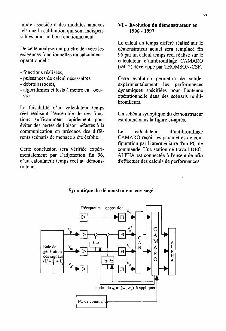
13-9
mixte associee a des modules annexes tels que la calibration qui sont indispen- sables pour un bon fonctionnement.
De cette analyse ont pu etre derivkes les exigences fonctionnelles du calculateur operationnel :
- fonctions rkalisees, - puissances de calcul necessaires, - debits associes, - algorithmies et tests a mettre en oeu-
vre.
La faisabilite d’un calculateur temps reel realisant l’ensemble de ces fonc- tions suffisamment rapidement pour dviter des pertes de liaison nefastes a la communication en presence des diffe- rents scknaris de menace a et6 Ctablie.
Cette conclusion sera verifiee experi- mentalement par l’adjonction fm 96, d’un calculateur temps reel au demons- trateur.
VI - Evolution du dhonstrateur en 1996 - 1997
Le calcul en temps differe realise sur le demonstrateur actuel sera remplace fm 96 par un calcul temps reel realise sur le calculateur d’antibrouillage CAMARO (ref. 2) developpe par THOMSON-CSF.
Cette evolution permettra de valider experimentalement les performances dynamiques specifiees pour l’antenne operationnelle dans des scenaris multi- brouilleurs.
Un schema synoptique du demonstrateur est donne dans la figure ci-aprk
Le calculateur d’antibrouillage CAMARO reGoit les paramhtres de con- figuration par Tintermediaire d’un PC de cornmande. Une station de travail DEC- ALPHA est connectee a l’ensemble afm d’effectuer des calculs de performances.
Synoptique du dbmonstrateur envisagb
RCcepteurs + opposition n
Baiede 1 I2 : gCnCration des signau ( U + i + J
I A
q R 0
codes du w= (w, , w2 ) A appliquer
PC de comman
13-10
Avec un cadencement identique a celui de l’antenne operationnelle, le demons- trateur permettra d’apprecier les perfor- mances de rejection en presence de plu- sieurs brouilleurs dkcoupis, et de quali- fier les techmques de gestion des coef- ficients d’opposition. Les performances dynamiques d’antibrouillage seront mesurkes en ter- mes de minimisation des pertes ou des reductions de service en presence de brouillage.
A l’issue de ces travaux’la totalite des sous-ensembles fonctionnels constitutifs de la fonction anti-brouillage auto- adaptatif (antenne, reception, opposi- tion, correlation numkrique, calcul et gestion temps reel des coefficients d’opposition) ainsi que leur regroupe- ment d’ensemble auront ete valides.
VI1 - RCfbrences
Presentation de la future genera- tion de systkmes de communica- tions militaires par satellite
%me symposium AGARD-MSP Juin 96.
Technologies numeriques pour une charge utile antibrouillke de telecommunications par satellite
52me symposium AGARD-MSP Juin 96.
14-1
Technologies Numkriques pour une Charge Utile Anti-BrouillCe de TClkcommunications par Satellites
M. Armand - Ph. Elleaume - B. Muller - J.P. Poux
7 Rue des Mathurins 9222 1 Bagneux Cedex
France J.F. Prirnard
T. Qui, onon Alcatel
TlioI11son-CSF AIRSYS
Thol11sol1-CSF TCC
Table des Matiitres
1 Prkface
2 Antibrouillage par OLS Mixte
3 PrCsentation de Camaro
3.1. Introduction
3.2. Architecture de Camaro
4 PrCsentation de I'Atelier Octane
5 Calculateur Spatial
6 Conclusions
1 Prkface
Les futures gknerations de systkmes de com- munication militaire par satellite nkcessiteront un surcroit de protection contre le brouillage et une plus grande facilitk d'interconnexions entre stations de diffkrents types. La satisfaction de ces bcsoins requiert pour la fonction dc transmission de disposer d'un calculateur d'an- tibrouillage.
Ce calculateur rkalise, de faqon nuinkrique, dif- fkrentes fonctions :
L'acquisition numkrique h haute frkquence d'kchantillonnage de blocs de donnkes en pro- venance du ou des canaux de transmission.
1
2
2
3
3
5
7
10
Le traitement intensif d'antibrouillage nkcessi- tant notamment la formation de matrices d'in- tercorrklation et la rksolution de systkmes li- nkaires.
Lcs traitements intelligents, effectuks en pa- rallkle de I'antibrouillage, de type calibration, localisation d'kmission, synchronisation tem- porelle et spatiale , correction de linkaritk des coinmandes d'attknuation et de rotation de phase de la consigne d'antibrouillage.
Sous I'egide de la Dklkgation Gknkrale de I'Ar- mement, Thomson-CSF a ktudik, pour des dis- positifs d'antibrouillage de type OLS mixte, un tel calculateur.
Les puissances de calcul de I'ordre de quelques centaines de Mkgaopkrations par seconde pour la partie rkpktitive et de quelques dizaines de Mkgainstructions par seconde pour la partie intelligente se pretent bien A une rkalisation en deux sous-ensembles :
Un systktne frontal, pour les traitements rk- pititifs tres gourmands en puissance de calcul brutc. Ce systkme est, pour l'essentiel, consti- t u k d'un ASIC prenant en charge la formation des matrices d'intercorrklation entre voies.
Une machine parallde multinoeuds pour I'en- semble des traitenients intelligents, rksolution dcs s y s t h e s linkaires compris.
Paper presented at the AGARD MSP Sh Symposium on "Space Systems as Contributors to the NATO Defence Mission", held in Cannes, France, 3-6 June 1996, and published in CP-580
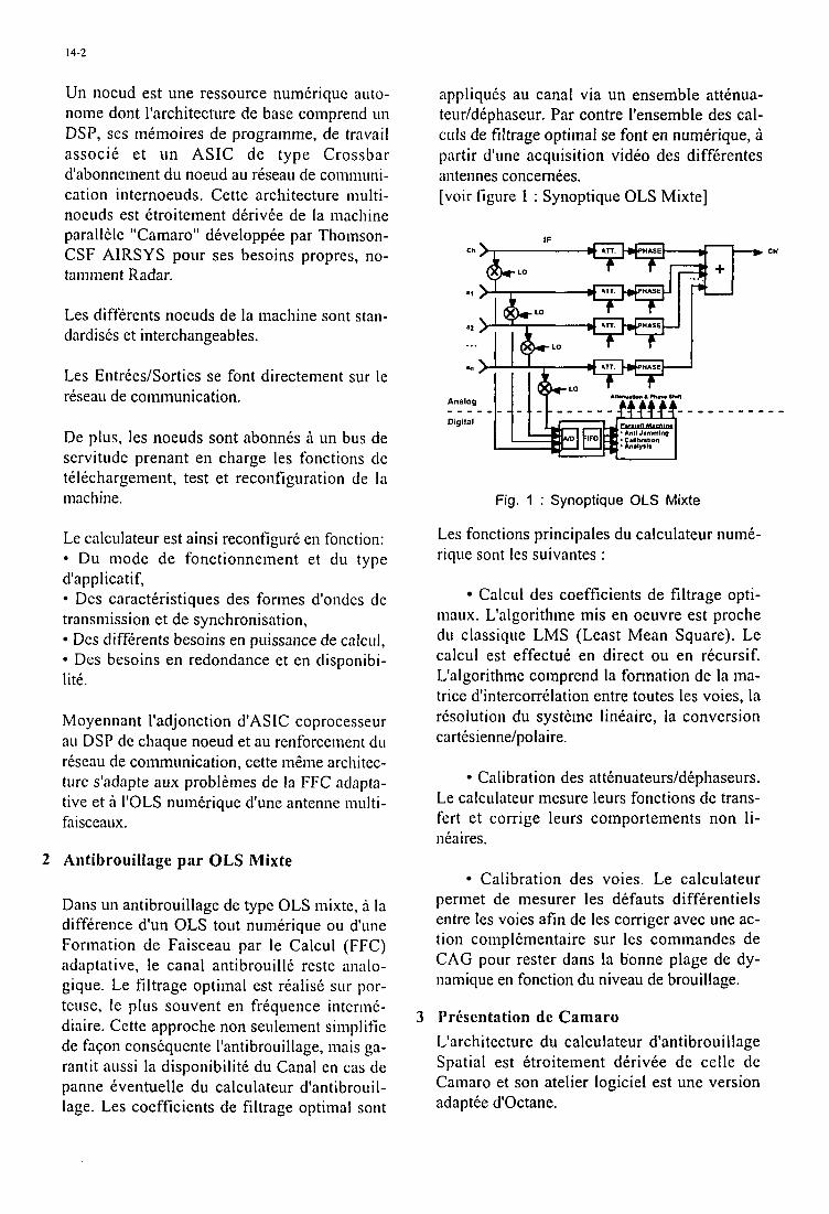
14-2
Un noeud est une ressource numkrique auto- nome dont l'architecture de base comprend un DSP, ses mkmoires de programme, de travail associe et un ASIC de type Crossbar d'abonnenient du noeud au rkseau de coinmuni- cation internoeuds. Cette architecture niulti- noeuds est ktroitement dkrivke de la machine parallele "Camaro" dkveloppke par Thomson- CSF AIRSYS pour ses besoins propres, no- tainiiient Radar.
Les diffkrents noeuds de la machine sont stan- dardisks et interchangeables.
Les Entrkes/Sorties se font directement sur le rkseau de communication.
De plus, les noeuds sont abonnks 6 un bus de servitude prenant en charge les fonctions de tklechargement, test et reconfiguration de la machine.
Le calculateur est ainsi reconfigurk en fonction: Du mode de fonctionnement et du type
d'applicatif, Des caractkristiques des formes d'ondes dc
transmission et de synchronisation, Des diffkrents besoins en puissance de calcul, Des besoins en redondance et en disponibi-
litk.
Moyennant I'adjonction d'ASIC coprocesseur au DSP de cliaque noeud et au renforcement du rkseau de communication, cette m i k e architec- ture s'adapte aux problemes de la FFC adapta- tive et A I'OLS numkrique d'une antenne multi- faisceaux.
2 Antibrouillage par OLS Mixte
Dans un antibrouillage de type OLS mixte, a la difference d'un OLS tout nuinkrique ou d'une Formation de Faisceau par le Calcul (FFC) adaptative, le canal antibrouillk reste analo- gique. Le filtrage optimal est realisk sur por- teuse, le plus souvent en frkquence intermk- diaire. Cette approche non seulement simplifie de faqon conskquente l'antibrouillage, mais ga- rantit aussi la disponibilitk du Canal en cas de panne kventuelle du calculateur d'antibrouil- lage. Les coefficients de filtrage optimal sont
appliquks au canal via un ensemble attknua- teur/dkphaseur. Par contre l'ensemble des cal- crils de filtrage optimal se font en numkrique, B partir d'une acquisition vidko des diffkrentes antennes concernkes. [voir figure 1 : Synoptique OLS Mixte]
ch'
Fig. 1 : Synoptique OLS Mixte
Les fonctions principales du calculateur numk- rique sont les suivantes :
Calcul des coefficients de filtrage opti- maux. L'algorithme mis en oeuvre est proche du classique LMS (Least Mean Square). Le calcul est effectuk en direct ou en rkcursif. L'algorithme comprend la formation de la ma- trice d'interconklation entre toutes les voies, la rksolution du systdme linkaire, la conversion cartksienne/polaire.
Calibration des attknuateurs/dkphaseurs. Le calculateur mesure leurs fonctions de trans- fert et corrige leurs comportements non li- nka i res.
Calibration des voies. Le calculateur permet de mesurer les dkfauts diffkrentiels entre les voies afin de les corriger avec une ac- tion complkmentaire sur les cominandes de CAG pour rester dans la bonne plage de dy- namique en fonction du niveau de brouillage.
3 Presentation de Camaro L'architecture du calculateur d'antibrouillage Spatial est ktroitement dkrivke de celle de Cainaro et son atelier logiciel est une version adaptke d'Octane.
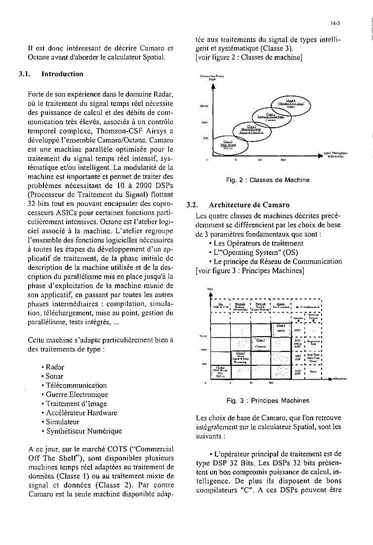
14-3
I1 est donc intkressant de dkcrire Camaro et Octane avant d'aborder le calculateur Spatial.
3.1. Introduction
Forte de son expkrience dans le domaine Radar, oil le traitement du signal temps riel nkcessite des puissance de calcul et des dkbits de com- munication trks klevks, associks a un contr6lc temporel complexe, Thomson-CSF Airsys a dkveloppk l'ensemble Camaro/Octane. Camaro est une machine parallkle optimiske pour le traitement du signal temps rkel intensif, sys- tkniatique et/ou intelligent. La modularite de la machine est importante et pennet de traiter des problknies nkcessitant de 10 A 2000 DSPs (Processeur de Traitement du Signal) flottant 32 bits tout en pouvant encapsuler des copro- cesseurs ASICs pour certaines fonctions parti- culikrement intensives. Octane est I'atelier logi- ciel associk a la machine. L'atelier regroupe I'ensemble des fonctions logicielles nkcessaircs a toiites les ktapes du dkveloppement d'un ap- plicatif de traitement, de la phase initiale de description de la machine utiliske et de la des- cription du parallklisnie mis en place jusqu'd la phase d'exploitation de la machine munie de son applicatif, en passant par toutes les autres phases i n termk d i a i res : coin p i 1 at i o n, si ni LI I a- tion, tklichargement, mise au point, gestion du parallilisme, tests intigrks, ...
Cette machine s'adapte particulikrement bien A des traitements de type :
Radar Sonar Telkcommunication Guerre Electronique Traiteinent d' Iinage Accelkrateur Hardware Simulateur Synthktiseur Numkrique
A ce jour, sur le march6 COTS ("Commercial Off The Shelf'), sont disponibles plusieurs machines temps rkel adaptkes au traitement de donn&es (Classe 1) ou au traitement inixte de signal et donnkes (Classe 2). Par contre Camaro est la seule machine disponible adap-
tee aux traitements du signal de types intelli- gent et systematique (Classe 3). [voir figure 2 : Classes de machine]
Fig. 2 : Classes de Machine
3.2. Architecture de Camaro Les quatre classes de machines dkcrites preck- deminent se diffkrencient par les choix de base de 3 parani&tres fondamentaux que sont :
Les Opkrateurs de traitement L"'0perating System" (OS) Le principe du Rkseau de Communication
[voir figure 3 : Principes Machines]
Fig. 3 : Principes Machines
Les choix de base de Camaro, que I'on retrouve intkgralernent sur le calculateur Spatial, sont les suivants :
L'opkrateur principal de traitement est de type DSP 32 Bits. Les DSPs 32 bits prksen- tent un bon compromis puissance de calcul, in- telligence. De plus ils disposent de bons compilateurs "C". A ces DSPs peuvent Ztre
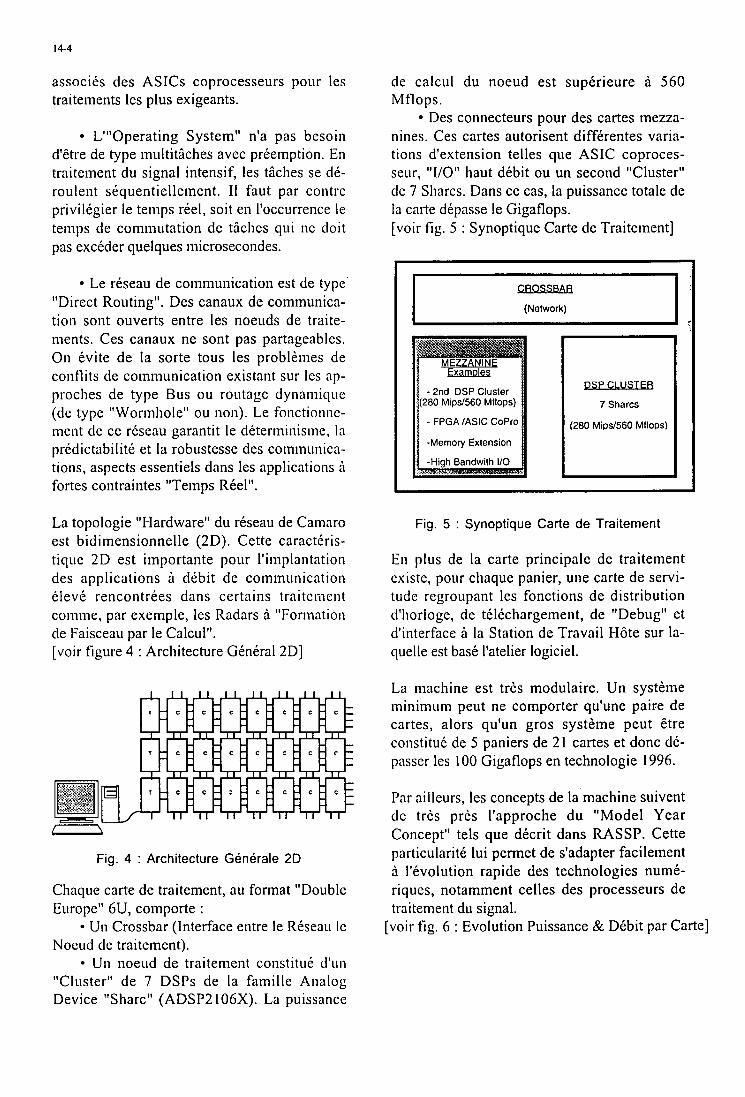
14-4
associks des ASICs coprocesseurs pour les traitements les plus exigeants.
L"'0perating System'' n'a pas besoin d'etre de type multitkhes avec prkemption. En traitement du signal intensif, les tkhes se dl- roulent slquentiellement. I1 faut par contre privilkgier le temps rkel, soit en l'occurrence le temps de commutation de tiiclies qui ne doit pas exclder quelques niicrosecondes.
Le rkseau de communication est de type "Direct Routing". Des canaux de communica- tion sont ouverts entre les noeuds de traite- nients. Ces canaux ne sont pas partageables. On kvite de la sorte tous les problkmes de conflits de communication existant sur les ap- proclies de type Bus ou routage dynaniique (de type 'tWormliole" ou non). Le fonctionnc- mcnt de ce rkseau garantit le dkterminisme, la prkdictabilite et la robustesse des communica- tions, aspects essentiels dans les applications A fortes contraintes "Temps Rkel".
La topologie "Hardware" du reseau de Caniaro est bidimensionnelle (2D). Cette caractlris- tiqiie 2D est importante pour l'implantation des applications dkbit de communication l l ev l rencontrees dans certains traitcmcnt coinme, par exemple, les Radars a "Formation de Faisceau par le Calcul". [voir figure 4 : Architecture Gknkral2Dl
Fig. 4 : Architecture Generale 20
Chaque carte de traitement, au format "Double Europe" 6U, comporte :
U n Crossbar (Interface entre le Rkseau I C Nocud de traitement).
U n noeud de traitement constituk d'iin "Clitster" de 7 DSPs de la famille Analog Device "Sharc" (ADSP2 106X). La puissancc
de calcul du noeud est supkrieure A 560 Mflops.
Des connecteurs pour des cartes mezza- nines. Ces cartes autorisent diffkrentes varia- tions d'extension telles que ASIC coproces- sew, "I/O" haut dkbit ou un second Tlusterll de 7 Sharcs. Dans ce cas, la puissance totale de la carte dkpasse le Gigaflops. [voir fig. 5 : Synoptique Carte de Traitement]
CROSSBAR (Network)
Fig. 5 : Synoptique Carte d e Traitement
En plus de la carte principle de traitement cxiste, pour chaque panier, une carte de servi- titdc rcgroupant les fonctions de distribution d'horloge, de tklkchargement, de "Debug" et d'interface a la Station de Travail HGte sur la- quelle est bask l'atelier logiciel.
La machine est trks modulaire. Un systime minimum peut ne comporter qu'une paire de cartes, alors qu'un gros systkme peut etre constituk de 5 paniers de 21 cartes et donc dk- passer les 100 Gigaflops en technologie 1996.
Par ailleurs, les concepts de la machine suivent de trks prks I'approche du "Model Year Concept" tels que dkcrit dans RASSP. Cette particularitk lui permet de s'adapter facilement a l'kvolution rapide des technologies numk- riques, notamment celles des processeurs de traitement du signal.
[voir fig. 6 : Evolution Puissance & Dkbit par Carte]
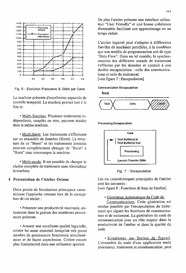
14-5
900
800
700
600
500
400 300
200
100
0
93 94 95 96 9 7 9 8
Fig. 6 : Evolution Puissance & Debit par Carte
La machine prksente d'excellentes capacitks dc contr6le temporel. La machine perinet tout A la fois le:
Multi-fonction. Plusieurs traiteiiients in- dkpendants, couplks ou non, peuvent rksider dam la insme machine.
Mu 1 ti -burst . Les trai teinents s'effec tuen t sur un ensemble de donnkes (Burst). La struc- ture de ce "Burst" et les traiteiiients associks p e 11 vent coni p 16 te men t changer de " B U rs t I' A "Burst" sans interroiiipre la machine.
Multi-mode. I1 est possible de changer la chaine complete de traitenient sans rkinitialiser la machine.
4 PrCsentation de I'Atelier Octane
Deux points de focalisation principaux c a m - terisent I'approche retenue lors de la concep- tion de cet atelier :
Prksenter une productivitk maximale, no- taniinent dans la gestion des noinbreux proccs- seurs prksents.
* Assurer une excellente qualitk logiciclle, critere lui aussi essentiel lorsqu'un trks grand nombre de processeurs fonctionne simultank- ment et de facon asynchrone. Critkre encorc plus fondamental dans une utilisation spatialc.
De plus I'atelier prksente une interface utilisa- teur "User Friendly" et une bonne cohkrence d'ensemble facilitant son apprentissage en un temps rkduit.
L'atelier logiciel peut s'adapter A diffkrentes faniilles de machines paralleles, A la condition que son modele de prograinmation soit de type "Data Flow". Dam un tel inodele, la synchro- nisation des diffkrents noeuds de traitenient s'effectue par les donnkes et conduit A une double encapsulation : celle des communica- tions et celle du traitement. [voir figure 7 : Encapsulation]
Communication Encapsulation
Burst
Data
Processing Encapsulation
Task
Test Buffer(s) In Test Buffer(s) Out
I
Processing
Launch Transfer DMA
Fig. 7 : Encapsulation
Les six caractkristiques principales de I'atelier sont les suivantes : [voir figure 8 : Fonctions de base de I'atelier]
Gknkration Automatiaue du Code de Communication. Cette gknkration est
rendue possible par l'encapsulation du traite- mcnt qui skpare les fonctions de communica- tion et de traitement. La gtnkration du code de coniniunication joue un r61e majeur dans la productivitk de l'atelier et dans la qualitk du code.
Simulateur sur Station de Travail. L'cnscmble du code d'une application multi proccsseur, traitement et communication, peut
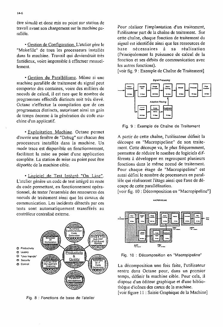
14-6
etre siniulk et donc mis au point sur station de travail avant son chargement sur la machine pa- rallde.
Gestion de Confirruration. L'atelier gire le "Makefile" de tous les processeurs installks dam la machine. Travail qui deviendrait trks fastidieux, voire impossible a effectuer manuel- lenient.
Gestion du Parallklisnie. Meme si une machine parallele de traitement du signal peut coniporter des centaines, voire des milliers de noeuds de calcul, il est rare que le nombre de prograniines effectifs distincts soit tris 6leve. Octane n'effectue la compilation que de ces programmes distincts, autorisant ainsi uii gain de tenips knorme a la gknkration du code ma- chine d'un applicatif.
Exploitation Machine. Octane permet d'ouvrir une fenetre de "Debug" sur chacun des processeurs installks dans la machine. Un mode trace est disponible en fonctionnement, facilitant la mise au point d'une application complete. La station de mise au point peut Etre dkportte de la machine cible.
Lociciel de Test Intkcrk "On Line". L'atelier gen6t-e un code de test integrk au reste du code pennettant, en fonctionnement opkra- tionnel, de tester I'ensemble des ressources des noeuds de traitement ainsi que les canaux de communication. Les incidents dktectks par ces tests son t auto mat i qu e in e n t trans fk re s a u contr6leur centralise externe.
0 Productivity 0 uuality 0 "User friendly" 0 Security 0 Control
Pour rtaliser /'implantation d'un traitement, l'utilisateur part de la chaine de traitement. Sur cette chaine, chaque fonction de traitement du signal est identifike ainsi que les ressources de base nkcessaires B sa real isat ion (Principalement la puissance de calcul de la foiiction et ses dkbits de communication avec les autres fonctions). [voir fig. 9 : Exernple de Chaine de Traitement]
Signal Processing
Adaplive Filleting I I 1 e
Fig. 9 : Exemple de Chaine de Traitement
A partir de cette chaine, l'utilisateur dkfinit la dkcoupe en "Macropipeline" de son traite- inent. Cette dkcoupe va, le plus frkquemment, permettre de rkduire le nombre de logiciels dif- fkrents a dkvelopper en regroupant plusieurs fonctions dans le meme noeud de traitement. Pour cliaque ktage de "Macropipeline" est aussi dkfini le nombre de processeurs en paral- Ide qui rtaliseront l'ktage ainsi que l'axe de de- coupe de cette parallklisation. [voir fig. 10 : Dkcomposition en "Macropipeline"
Ch-.
Fig. 10 : Decomposition en "Macropipeline"
La dkcomposition une fois faite, l'utilisateur rentre dans Octane pour, dans un premier temps, dkfinir la machine cible. Pour cela, i l dispose d'un kditeur graphique et d'une biblio- th2que d'ic6nes des cartes de la machine. [voir figure 11 : Saisie Graphique de la Machine]
Fig. 8 : Fonctions de base de I'atelier
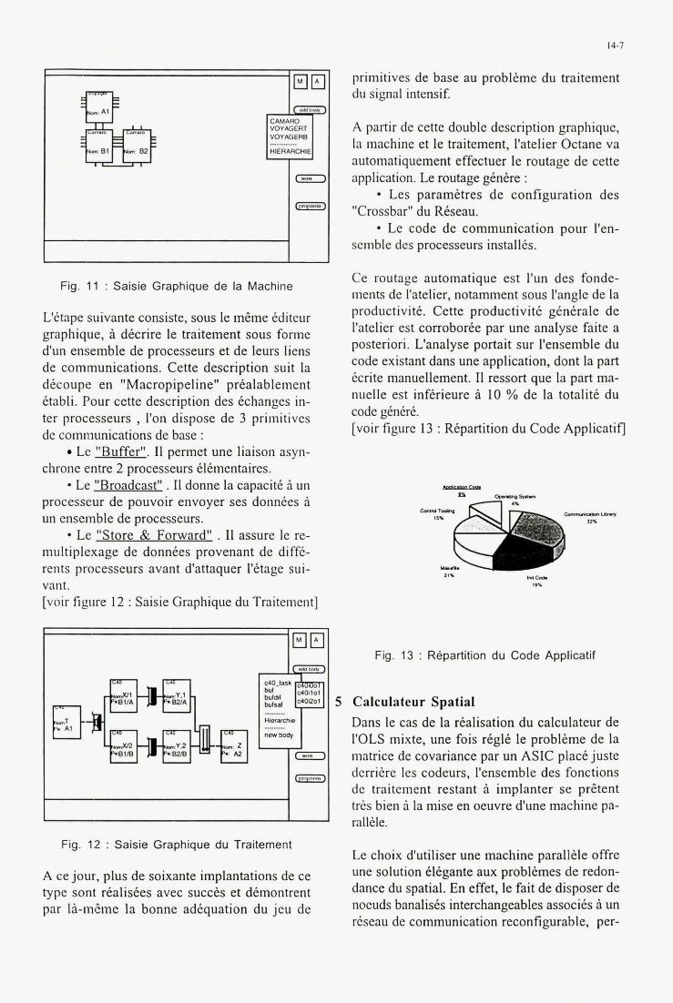
I 4-7
Imtml.l
CAMARO VOYAGER1 VOVLOERB
HIERARCHIE
derrihre les codeurs, I'ensemble des fonctions de traitement restant B implanter se prZtent trks bien i la mise en oeuvre d'une machine pa-
Fig. 11 : Saisie Graphique de la Machine
L'itape suivante consiste, sous le m&me Cditeur graphique, i dtcrire le traitement sous forme d'un ensemble de processeurs et de leurs liens de communications. Cette description suit la dtcoupe en "Macropipeline" prtalablement ttabli. Pour cette description des &changes in- ter processeurs , I'on dispose de 3 primitives de communications de base :
Le "Buffer". I1 permet une liaison asyn- chrone entre 2 processeurs tltmentaires. - Le "Broadcast" . I1 donne la capacitt a un processeur de pouvoir envoyer ses donnees a un ensemble de processeurs.
Le "Store & Forward" . I1 assure le re- multiplexage de donntes provenant de difft- rents processeurs avant d'attaquer l'ttage sui- vant. [voir figure 12 : Saisie Graphique du Traitement]
primitives de base au problime du traitement du signal intensif.
A partir de cette double description graphique, la machine et le traitement, I'atelier Octane va automatiquement effectuer le routage de cette application. Le routage gtnkre :
Les paramktres de configuration des "Crossbar" du Rtseau.
* Le code de communication pour I'en- semble des processeurs installes.
Ce routage automatique est I'un des fonde- inents de I'atelier, notamment sous Pangle de la productivitt. Cette productivite gentrale de I'atelier est corroboree par une analyse faite a posteriori. L'analyse portait sur I'ensemble du code existant dans une application, dont la part tcrite manuellement. I1 ressort que la part ma- nuelle est infkrieure a 10 % de la totaliti du code genere. [voir figure 13 : Repartition du Code Applicatifl
Fig. 13 : Repartition du Code Applicatif
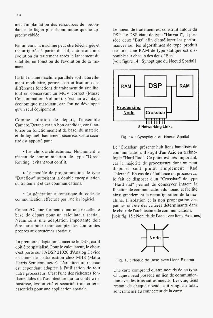
met l'implantation des ressources de redon- dance de faqon plus Cconomique qu'une ap- proche c5blte.
Par ailleurs. la machine peut itre tdtchargie et reconfigurte a partir du sol, autorisant uiie Cvolution du traitement aprhs le lancement du satellite, en fonction de l'tvolution de la me- nace.
Le noeud de traitement est construit autour du DSP. Le DSP Ctant de type "Harvard", il pos- side deux "Bus" afin d'amC1iore.r les perfor- mances sur les algorithmes de type produit scalaire. Une RAM de type statique est dis- ponible sur chacun des deux "Bus". [voir figure 14 : Synoptique du Noeud Spatial]
Le fait qu'une machine parall& soit naturelle- ment modulaire, permet son utilisation dans difftrentes fonctions de traitement du satellite, tout en conservant un MCV correct (Masse Consommation Volume). C'est un avantage iconomique marquant, car I'on ne dtveloppe qu'un seul tquipement.
Comme solution de dtpart, I'ensemble Camaro/Octane est un bon candidat, car il au- torise un fonctionnement de base, du matiriel et du logiciel, hautement stcurist. Cette stcu- rite est apportt par :
- Les choix architecturaux. Notaiiiinent le rkseau de communication de type "Direct Routing" Cvitant tout conflit.
Le modtle de programmation de type "Dataflow" autorisant la double encapsulation du traitement et des communications.
- La gtntration automatique du code de communication effectute par I'atelier logiciel.
Camaro/Octane forment donc m e excellente base de dCpart pour un calculateur spatial. Ntanmoins une adaptation importante doit Etre faite pour tenir compte des contraintes propres aux systemes spatiaux.
La premite adaptation conceme le DSP, car il doit Etre spatialist. Pour le calculateur, le choix c'est port6 sur I'ADSP 21020 d'Analog Device en cours de spatialisation chez MHS (Matra Harris Semiconductor). L'architecture retenue est cependant adaptte a l'utilisation de tout autre processeur. C'est l'une des richesses fon- damentales de I'architecture qui lui conf6re ro- bustesse, Cvolutivitk et stcuritt, trois crithes essentiels pour une application spatiale.
Processin I dr-J+ Crossbar
8 Networking Links
Fig. 14 : Synoptique du Noeud Spatial
Le "Crossbar" prtsente huit liens banalists de communication. II s'agit d'un Asic en techno- logie "Hard Rad". Ce point est tr6s important, car la majoritt de processeurs dont on peut disposer sont plut6t simplement "Rad Tolerant". En cas de dtfaillance du processeur, le fait de disposer d'un "Crossbar" de type "Hard rad" permet de conserver intacte la fonction de communication du noeud et facilite ainsi grandement la reconfiyration de la ma- chine. L'isolation et la non propagation des pannes ont ttt des critCres dtterminants dans le choix de I'architecture de communications. [voir fig. 15 : Noeuds de Base avec liens Extemes]
m Fig. 15 : Noeud de Base avec Liens Externe
Une carte comprend quatre noeuds de ce type. Chaque noeud posskde un lien de communica- tion avec les trois autres noeuds. Les cinq liens restant de chaque noeud, soit vingt au total, sont raments au connecteur de la carte.
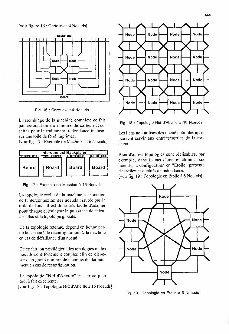
14-9
[voir figure 16 : Carte avec 4 Noeuds]
Backplane
- I
Fig. 16 : Carte avec 4 Noeuds
L'asseinblage de la machine coinplkte ce fait par association du noinbre de cartes ndccs- saires pour le traitement, redondance incluse, sur Line toile de fond iniprimke. [voir fig. 17 : Exeinple de Machine A 16 Noeuds]
Fig. 17 : Exemple d e Machine a 16 Noeuds
La topologie rkelle de la machine est fonction de I'iiiterconnexion des noeuds assurke par la toile de fond. I1 est donc trks facile d'adapter pour chaque calculateur la puissance de calcul installCe et la topologie globale.
De la topologie retenue, dkpend en bonne par- tie la capacitk de reconfiguration de la machine en cas de dkfaillance d'un noeud.
De cc fait, on privilkgiera des topologics ou les noeuds sont forteinent couplks afin de dispo- scr d'un grand noinbre de cheinins de ddroutc- incnt en cas de reconfiguration.
La topologie "Nid d'Abcille" est sur ce plan tout a fait excellente.
[voir fig. 18 : Topologie Nid d'Abeille a 16 Noeuds]
Fig. 18 : Topologie Nid d'Abeille a 16 Noeuds
Les liens non utilisks des noeuds pkriphkriques peuvent servir aux entrkes/sorties de la ina- chine.
Bien d'autres topologies sont rkalisables, par cxcinple, dans le cas d'une machine h six noeuds, la configuration en "Etoile" prksente d'excellentes qualitks de redondance. [voir fig. 19 : Topologie en Etoile h 6 Noeuds]
m Fig. 19 : Topologie en ctoile a 6 Noeuds
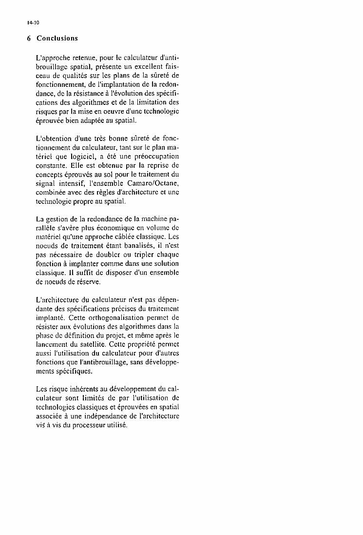
6 Conclusions
14-10
L'approche retenue, pour le calculateur d'anti- brouillage spatial, prksente un excellent fais- ceau de qualitks sur les plans de la silrete de fonctionnement, de I'implantation de la redon- dance, de la rksistance ii l'kvolution des spkcifi- cations des algorithmes et de la limitation des risques par la mise en oeuvre d'une technologie kprouvke bien adaptte au spatial.
L'obtention d'une trks bonne silretk de fonc- tionnenient du calculateur, tant sur le plan ma- teriel que logiciel, a ktk line prkoccupation constante. Elle est obtenue par la reprise de concepts kprouvks au sol pour le traitement du signal intensif, l'ensemble Camaro/Octane, combinke avec des r6gles d'architecture et une technologie propre au spatial.
La gestion de la redondance de la niachine pa- rallele s'avere plus kconomique en volume dc niatkriel qu'une approche ciiblke classique. Les noeuds de traitement etant banalisks, i l n'cst pas nkcessaire de doubler ou tripler chaque fonction ii implanter comme dans une solution classique. I1 suffit de disposer d'un ensemble de noeuds de rkserve.
L'architecture du calculateur n'est pas dkpen- dante des spkcifications prkcises du traitement implantk. Cette orthogonalisation permct dc resister aux kvolutions des algorithines dans la phase de dkfinition du projet, et inkine apres le lancenient du satellite. Cette proprikte perinet aussi l'utilisation du calculateur pour d'autres fonctions que l'antibrouillage, sans dkveloppe- ments specifiques.
Les risque inhkrents au dkveloppement du cal- culateur sont limitks de par l'utilisation de technologies classiques et kprouvkes en spatial associke a une indkpendance de I'architecture vis' h vis du processeur utilisk.
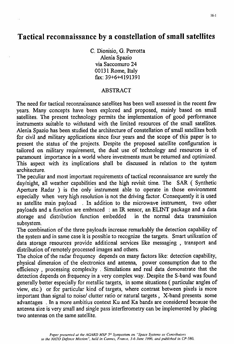
16-1
Tactical reconnaissance by a constellation of small satellites
C. Dionisio, G. Perrotta Alenia Spazio
via Saccomuro 24 00 13 1 Rome, Italy fax: 39+6+4191391
ABSTRACT
The need for tactical reconnaissance satellites has been well assessed in the recent few years. Many concepts have been explored and proposed, mainly based on small satellites. The present technology permits the implementation of good performance instruments suitable to withstand with the limited resources of the small satellites. Alenia Spazio has been studied the architecture of constellation of small satellites both for civil and military applications since four years and the scope of this paper is to present the status of the projects. Despite the proposed satellite configuration is tailored on military requirement, the dual use of technology and resources is of paramount importance in a world where investments must be returned and optimized. This aspect with its implications shall be discussed in relation to the system architecture. The peculiar and most important requirements of tactical reconnaissance are surely the dayhight, all weather capabilities and the high revisit time. The SAR ( Synthetic Aperture Radar ) is the only instrument able to operate in those environment especially when very high resolution is not the driving factor. Consequently it is used as satellite main payload . In addition to the microwave instrument, two other payloads and a hnction are embraced : an IR sensor, an ELINT package and a data storage and distribution hnction embedded in the normal data transmission subsystem. The combination of the three payloads increase remarkably the detection capability of the system and in same case it is possible to recognize the targets. Smart utilization of data storage resources provide additional services like messaging , transport and distribution of remotely processed images and others. The choice of the radar frequency depends on many factors like: detection capability, physical dimension of the electronics and antenna, power consumption due to the efficiency , processing complexity . Simulations and real data demonstrate that the detection depends on frequency in a very complex way. Despite the S-band was found generally better especially for metallic targets, in some situations ( particular angles of view, etc.) or for particular kind of targets, where contrast between pixels is more important than signal to noise/ clutter ratio or natural targets , X-band presents some advantages . In a more ambitius context Ku and Ka bands are considered because the antenna size is very small and single pass interferometry can be implemented by placing two antennas on the same satellite.
Paper presented at the AGARD MSP Sh Symposium on “Space Systems as Contributors to the NATO Defence Mission”, held in Cannes, France, 3-6 June 1996, and published in CP-580.
16-2
1. Introduction
The satellite system under consideration is an enhanced version of the COSMO system being proposed for civilian applications (see Ref [ 1],[2]) which, with suitable modifications and additions to the payloads complement, is well suited to support tactical operations.
Tactical applications stress the importance of short revisit intervals over selected sites and the use of high resolution SAR instruments for the detection of surface targets independently from weather and sun illumination. This task is achieved implementing a constellation of small dedicated satellites carrying SAR instruments. The addition of infrared sensors, with high to moderate geometric resolution, say in the 20 m range, seems also an important addition for tactical uses when data fksion is considered. Electronic Intelligence, meant as a listening capability, was also considered in the preliminary mission design, since it may reveal an increase of electronic activity from radars, or ground-based communication equipment, possibly linked to the enemy's military activity. Again, the utilization of ELINT data must always be seen in a data fbsion context. Both tasks require implementing a second dedicated constellation of small satellites, which is here proposed to be optionally added to the first one. To insure real-time access to spacecraft assets, both in terms of commanding the operating modes, activation times and fimctions of the spaceborne instruments as well as near real-time retrieval of satellite gathered data, indipendently from the time- evolving satellites' orbital positions and Mission Control Center location, the satellite constellation is assisted by a Multi Satellite Data Relay System (MSDRS) which is proposed to be unconventionally made up by a fbrther constellation of six small satellites in IC0 (Intermediate Circular Orbit) interconnected via intersatellite links. The key elements of this system architecture, including both the tactical Surveillance constellation, the IR plus ELINT satellite constellation and the MSDRS complement are below discussed and reviewed.
2. The SAR satellite constellation
Previous studies have shown that, for a tactical scenario, a revisit interval of between twelve and six hours is necessary to support tactical operations. In addition a good geometric resolution, of the order of 1 m, is necessary to pinpoint targets of tactical interest whose general features and deployment or presence in the tactical scenario may be known from previous activity of strategic observation satellites, or ground intelligence. Day-night and all-weather operation is mandatory for tactical support, which rules out optical sensors in favour of radar instruments which, due to the resolution requirements, must be S A R s . To meet the revisit intervals requirements at any latitude, a constellation of five small satellites injected in a 500 km sunsynchronous transverse orbit is proposed. Full accessibility to any point on Earth within the +- 85" latitude belt is insured by relying on both spacecraft roll steering and cross-track electronic beam steeering to be able to access, in sequence, target areas spaced apart by about 400 km within a fraction of a second. With this system configuration it is possible to have access to any site in the above latitude band with a maximum delay of 12 hours at the equator decreasing to 4-6 hours at middle latitudes. Adding a second ring of five satellites, this time in a near-noon plane, halves the mean
16-3
revisit interval to six hours for sites at the equator down to 2-3 hours at middle latitudes.
The SAR instruments operates at X-band , in a Stripmap mode, and can provide a 1- look geometric resolution of the order of 1 m over a swath which, depending on the off-nadir angle, is in the 10 to 20 km range. The choice of the X-band ,over S-band, is motivated by comparable or better contrast ratios for certain surface targets. The S A R antenna dimensions are 2 m in the along-track direction by about 4 m in the cross-track direction. The peak pulse power is of the order of 3 kW with a duty of 5 to 10% depending on the off-nadir angle, for which a maximum value around 50' is projected. Since in a tactical scenario only few images per orbit are required, an instrument operating duty of 5 % of the orbit period was found more than adequate, with significant attendant savings in terms of the mean orbit energy requirements. To cope with the high data volumes generated, one takes advantage of temporary storage and near-lossless advanced data compression techniques. As an example, exploiting chaotic compression - a technique being developed in Italy by TER - raw SAR data can be compressed by a 20:l factor without appreciable losses in image content, which also means target detection and, compatibly with the geometric resolution, target identification. Accordingly each SAR raw image is temporarily stored in a buffer, then subjected to compression and sent to ground via the above mentioned Data Relay satellite system at much lower speeds, thus exploiting the continuous visibility of the data relay satellites from the Surveillance satellite. Assuming 0.8 Gbyte per raw SAR uncompressed image, 40 Mbyte after compression and a transmission bit rate of 8 Mbit/sec only, the transfer time of each compressed image to the Mission Control Center will take 40 seconds: which can be considered a near- real time data transfer to all practical effects. A redundant mass memory of 8 Gbit will make up the necessary storage means to be able to process and store a second SAR image, taken at a short time interval from the previous one (this is an important requirement for a tactical scenario) while the latter is being transmitted to ground via the relay network.
The estimated SAR payload mass, taking advantage of the recent technology improvements, can be kept within 100 kg; the data compression and storage system will add another 20 kg for a total of 120 kg. The DC power consumption , at full operation, is around 800 W, including fast beam steering, data compression and storage. However, considering an operational orbital duty of 5 % - outside which the bulk of power consuming units is switched off - the mean orbit energy demand should not exceed 260 Whr, which can be easily met with a medium size solar power plant.
3. The IR / ELINT satellite constellation
Besides the SAR satellite constellation, a second constellation of small satellites has been conceived and preliminarly sized, to cope with the additional requirement of detecting traces of military-related activities which can manifest under the form of thermal or radiofrequency emissions.
3.1 The Infrared sensor
To make sense a thermal imager should have a geometric resolution better than 30 m, to be able to pick hot spots due to heat-generating artifacts, above the ground thermal emission. At this resolution, the size of an infrared imager is not such to be easily accommodated on the same small satellite that carries the SAR instrument, even if , in
I
16-4
principle, the instrument could be flown in the same transverse sunsynchronous orbit where the SAR satellites will be conveniently injected. Taking into account both the desirability for an ELINT package (which would be accomodated along with the thermal imager on the same platform), a second small constellation of six satellites, flying at a lower altitude around 350 km, seems justified. Each spacecraft would carry three angularly squinted infrared telescopes with an aperture of 40 cm, a short focal lenght, and a viewing arc of 20" each, thus providing three contiguous coverage strips for a total viewing arc of 60" or 350 km on ground. At nadir, the projected resolution at midband is about 20 m. The focal plane of each telescope would carry an assembly of about 6000 detectors working in the full 8-12 micron band. The estimated mass of the complex of three telescopes and electronics is around 120 kg. The payload would generate a data volume around 50 Mbidsec, which can be losslessly compressed by a factor of four becoming of the same order of magnitude of the compressed dataflow from the S A R payload, and can be thus relayed through the Data Relay network . The estimated DC power consumption is around 300 W; however taking into account the mean orbital duty - of the order of 15 % - and the units always on even in cruise mode, the mean orbit energy requirement is estimated to be around 80Whr. The six satellites of the constellation are injected by triplets spaced by 120' , in two sunsunchronous orbital planes, angularly spaced by about +-45" with respect to the SAR constellation orbit plane laying, so that the infrared satellites overpass the sites during the morning and afternoon hours as well as during the late evening and during the night. The mean revisit interval is around six hours for sites at the equator, decresing to a few hours for sites at higher latitudes.
3.2 TheELINT package
The listening capability has been limited to the L, S and X bands for pinpointing hostile long and medium range surveillance and tracking radars. As a starting point we have considered the capability of locating these emitters within few km, sufficient to direct air-raids, and to discern their key characteristics such as operating frequency, PRF, modulation, to identifi at least the emitter type. For the intended purpose the ELINT coverage is an annular ring tangent to the Earth as seen from the satellite orbital altitude: in this way the radar emissions from the radar beam, usually directed towards the horizon, or from the close-in sidelobes, will have the greatest probability of thus maximizing the detection sensitivity. Preliminary link budgets show that a satellite antenna spotbeam of about 12 degrees with a boresight canted by about 57" with respect to the local nadir, would provide the necessary gain to detect a 100 kW pulsed radar, when looking at it through the radar antenna sidelobes, as well as a reasonable coverage. Implementing a mechanically spinning antenna, at 3 revolutions per minute, the resulting coverage will be in form of an annular ring with an outer diameter of about 2000 km and a depth of 1300 km. As the satellite moves in its orbit, the annular ring sweeps an area as wide as its projected diameter. Besides, during one antenna revolution (20 seconds) the annular footprint advances by about 150 km, on Earth, implying that, depending on the satellite-emitter geometry, the latter may remain within the annular ring for up to 8 revolutions and thus can be observed with different aspect angles, giving rise to a data sequence enhancing its detection and location. To implement the required coverage, the ELINT antenna will be made by three 80 cm diameter reflectors operating at L, S and X band, mounted at 120" on the same spinning platform. A two-axis monopulse feed system will be used to improve the
entering the satellite antenna,
location accuracy of the ground emitters. At the lower frequencies the predicted ‘single measurement’ location accuracy is around 15 km, at the coverage edge: this can be considerably improved by both observing the apparent emitter location as the satellite moves in its orbit and combining multiple data set obtained from subsequent satellite passes. The antenna overse at X band even allows implementing multiple beams in the elevation plane, to krther pushthe achievable location accuracy. At 3 rev/min each potential target will remain in the rotating antenna 3 dB beamwidth for 660 msec, available for signal analysis hence emitter detection and identification. The receiver architecture and technology is a matter of technology trade-offs: a parallel channellized approach, using electro-optical technology , appears a good candidate for the assumed 0.5 GHZ analysis bandwith at each of the three operating frequencies. Assuming to perform on board all signal processing, the data rate generated by the ELINT package has been estimated to be around 30 kbidsec., thus negligeable with respect to the data volume generated by the infrared payload. The estimated ELINT payload mass of 50 kg is due mainly to the spinning antenna platform, wherein lightweight techniques can be however adopted. The estimated DC power consumption is around 200 W, including processor and spinning table. Again, taking into account the mean orbital duty, the required orbit energy turns out to be around 80 whr.
3. The Multi Satellite Data Relay System
The operation of a tactical constellation implies to command and control in real time the spacecraft operation from a Mission Control Center independently fiom the orbital position of the satellites, and the ability of receiving the satellite gathered data in near real time, to support the tactical operations. As an alternative to the conventional approach of using a pair of geostationary satellites, we considered solutions based on a constellation of IC0 satellites interconnected by intersatellite links, to improve the coverage, operational flexibility and reduce costs. The full results of this study, klly in- house funded, will be reported in a future paper: here we will only give a summary of the most appropriate system configuration. The MSDRS (Multi Satellite Data Relay System) will consist of three satellites in a near polar orbit and three satellites in a near equatorial orbit , both with an orbit period of about six hours. Each triplet is interconnected via intersatellite links, and has means to communicate with ground terminals when in view of the satellites. as well as with the LEO satellites.
The intersatellite links are fundamental to guarantee a 100% connectivity between each LEO satellite and any ground station independently fiom the orbital position of either satellites. The MSDRS system allows managing the multiple data flows originated by, or destined to, the LEO satellites with rather simple payloads, also thanks to the reduced datarates owing to the advanced compression techniques adopted. The MSDRS configuration does also provide inherent redundancy in that multiple paths are available between each ground station and any LEO satellite of the constellation, enhancing the probability of being able to carry out a task (sending commands or receiving data) even in case of partial or total failures of one of the relay satellites.
The communication package will consist of - a dual antenna Intersatellite link section, with two opposite looking fixed mounted antennas of 60 cm diameter and two 5 W transmitters operating at 60 Ghz; - an Interorbit link section, also operating at 60 Ghz, provided with two mechanically steerable antennas of 30 cm diameter to provide two simultaneous and independent
16-6
accesses from two LEO satellites transmitting lOMbit/sec datastreams from LEO terminals equipped with 30 cm steerable antennas and 10 W transmitters; - a ground-to-satellite link package, operating at 20/30 Ghz, which includes a 60 cm diameter dual frequency steerable antenna and a 5 W transmitter, supporting up to 3 simultaneous downlinks at 10 Mbit/sec, when operating in conjunction with a Mission Control Station equipped with a 3 m diameter antenna; - an S-band dual transponder, able to: a) receive commands from ground and either to terminate them onboard or to retransmit them to the LEO satellite(s) in view, or to reroute them to the nearest data relay satellite; and b) transmit DRS generated housekeeping telemetries, or accepting and retransmitting to ground telemetry signals generated by the LEO satellite in view, or to send to ground telemetry signals originated by a non visible LEO satellite and routed via the nearest relay satellite. All data channels are demodulated and regenerated on board to implement data rerouting; a switching matrix, operated under ground control, is used to establish the interconnection paths for the various links: single hop LEO to ground via the DRS and multiple hops LEO to ground via interorbit and intersatellite links, for both the high speed (10 Mbit/sec) data channels and the low speed CMDs and TLM data.
The communication package mass is estimated around 80 kg, with a Dc power consumption of 150 W ; nevertheless the projected operational orbital duty will, probably, not exceed a 30% value, this impacting positively the spacecraft energy balance. The practical implementation of the satellite for the MSDRS approach requires a small satellite of about 300 kg at launch , about 40% of which for LEO to IC0 transfer, hence a net drymass of the order of 180 kg. The small size allows implementing the constellation with two launches of three satellites each in the two specified orbital planes.
The equipment installed on board each LEO satellite, consisting in a 60 Ghz 10 W modulator and transmitter, and a steerable 30 cm antenna will have an estimated mass around 15 kg with a DC power consumption of 80 W; for an operating orbital duty of 15 % (worst case), the orbital energy requirement is less than 15 Whr.
4. The satellite for the LEO constellations
Considering the envelope of the payloads requirements, respectively 135 Kg and 275 Whr mean orbital energy for the S A R satellites, and 185 kg and 175 Whr mean orbit energy for the IR/ELINT satellites, it turns out that the same basic platform can be adapted for both missions , by trading the larger payload mass of the IRELINT satellites with the reduced energy demand. Assuming a payload fraction around 0.5 of the drymass the spacecraft weight would be in the 350-400 kg range, to which a suitable propellant mass for orbit keeping will have to be added for a mission lifetime of at least 5 years. This may lead to a launch mass of the order of half a ton, which is compatible with the launch capability of nearly all small launchers being developed and also with multiple launches with larger vehicles. The main platform characteristics would not be dissimilar, except minor points, from those already described with reference to the proposed COSMO system for civil applications ( see e.g. Ref [3]).
16-7
5. Conclusions
A system architect1
References
re capabl to satis@ high revist time and high spatial re olution images has been presented as derived fiom the civil COSMO-project. The same platform could be adopted to complement the S A R payload with military application sensors.
[l] G. Perrotta, P. Xefteris 'The market for high resolution frequent revisits remote sensing services and the opportunities offered by the COSMO System'; 1st International Symposium on 'The Expansion of the Remote Sensing Market'; Paris, March '95;
[2] G. Perrotta ' An update on the COSMO project'; The Space Congress, Bremen, May '95;
[3] G. Perrotta ' Progress in the definition of the COSMO project'; paper IAF-95- B.2.06; 46th IAF Congress, Oslo, October '96;
[4] 'I SAR payload design for small satellite"
INTERNATIONAL SYMPOSrUM ON SATELLITE COMMUNICATION AND REMOTE SENSING, sept .95, XIAN
C. Dionisio, G. Perrotta, L. Sbardella, A. Torre:
[5] C. Dionisio E. Zampolini: "Frequency Selection and Multipolarity for Hard Target Detection", Proceding of IGARSS 94.

17-1
Interpretation of Passive Microwave Radiances for Tactical Applications: Current and Future Capabilities of the Defense Meteorological Satellite Program (DMSP)
Donald J. Boucher Bruce H. Thomas
THE AEROSPACE CORPORATION Post Office Box 92957, MU715
Los Angeles, CA 90009-2957 USA
Charles Holliday AIR FORCE GLOBAL WEATHER CENTRAL
Offutt Air Force Base Omaha , NE 98 1 13-4000 USA
1. Introduction
The DMSP program is the Department of Defense polar satellite system chartered to provide high quality meteorological data to strategic planners at major military command centers such as Air Force Global Weather Central in Omaha, Nebraska, as well as to tactical forces in the field. DMSP has a long history of flying state-of-the-art microwave instruments that derive vertical temperature and water vapor profiles, and detailed surface and near-surface properties such as soil moisture, and ocean surface wind speed. These microwave sensors compliment the prime sensor, the Operational Linescan System (OLS). The OLS is a cross-track scanning cassegrain telescope that samples in the visible and infrared wavelengths, featuring near constant horizontal resolution across the scan. Figure 1 shows a Advanced Very High Resolution Radiometer (AVHRR) channel 1 at 0.4-0.6 microns ( I . 1 Km resolution at nadir only) . At the edge of scan, the AVHRR pixels become elongated, whereas the OLS remains nearly constant. The data from Figure 1 were taken at the Aerospace real-time groundstation with DMSP Flight 11 transiting at 14502 on 26 April of 1995, and NOAA 12 at 15412 on the same day. The coverage of these passes were virtually identical, but the difference in resolution between the two sensors is very apparent. The OLS has an additional capability of being able to image. in the visible at night making use of reflected moonlight. Figure 2 is an example of the low light capability showing Japanese fishing fleets in the Pacific off the coast of Japan.
DMSP has recently flown the first operational water vapor profiler in the microwave regime (the Special Sensor Microwave Water Vapor Profiler SSM/T-2, hereafter referred to as T-2) to compliment the microwave temperature sounding capabilities of the Special Sensor Microwave Temperature Sounder or SSM/T- 1 (hereafter referred to as T-I) as well as the microwave imager, the SSM/I (hereafter MD). In the following sections, these sensors are discussed in terms of using the measured calibrated radiances as useful imager that can characterize background types, changes in surface emissivity, rain detectors, and as indicators of suspended ice. One “visual algorithm” is discussed, and a more complicated numerical weather prediction visual technique is outlined.
2. Brief Description of DMSP Microwave Instruments: Current Capability
The T-1 and T-2 are through nadir or equivalently, cross-track scanning (perpendicular to the velocity vector of the spacecraft) instruments having the property (like the AVHRR) that the pixel size grows as a function of scan angle. The T-1 was originally flown as an experiment in the early 1980’s in order to demonstrate the capabilities of performing temperature profiling in the 50-60 Ghz regime. The T-1 has seven channels with very low noise characteristics, typically less than 0.4 Kelvin at all frequencies. The T-2 was added to the T-1 in the early 1990’s again as an experiment to prove the capabilities of water vapor profiling using three channels on the wing of the very strong 183 Ghz water vapor resonance line, one window
Paper presented at the AGARD MSP SIh Symposium on “Space Systems as Contributors to the NATO Defence Mission”, held in Cannes, France, 3-6 June 1996, and published in CP-580.
17-2
channel at 91.655 Ghz, and a mixed window, atmosphere channel at 150 Ghz. The noise characteristics of the T-2 are equivalent to the T- 1. Vertical resolution in the atmosphere is achieved by sampling in frequency on the wings of a strong absorption features. The window channels provide surface characterization in order to correct atmosphere channels for any surface contamination. The M/I is a very different device in that the field-of-view is fixed with respect to nadir, and the instrument scans in a continuous circular fashion taking data approximately 50 degrees either side of the satellite sub-track, and calibrating during the remainder of the scan. M/I calibrated radiances are used today as “imagery” products. The M/I has four frequencies from 19- 85 Ghz. The channels are all dual-polarized with the exception of the 22 Ghz. The first M/I flew on Flight 8 in 1987 and is now a key sensor for the Air Force and Navy forecasters. The T-1 and T-2 are used operationally as “profilers” and not as “imagers”. The following section discussed the DMSP microwave sensor suite in terms of “imagery” data only.
3. Microwave Radiances As Imagery
In order to fully exploit all DMSP and NOAA microwave data (both cross-track and conical sensors) as imagery, there are adjustments to the radiances that are required merely due to the differences in viewing geometry. Ideally, quantitative correlation of data from the conical MA, and the cross-track T-1 and T-2 is required. In order to compare data, the cross-track scanning radiances must be adjusted for polarization rotations. Figure 3 illustrates the magnitude of the adjustment. This scatterplot shows M/I 85 Ghz Horizontal polarization vs T-2 91.655 Ghz mixed polarization. The theoretical envelope in which the radiances fall is shown by the two heavy lines. Points falling outside this envelope are cloud contaminated pixels. Figures 4 and 5 illustrate M/I 85 and T-2 91.655 adjusted imagery.
Two techniques will be illustrated in order to provide insight into microwave radiance imagery interpretation. The first technique takes advantage of today’s powerful workstations and 24 bit display devices. Our first “visual algorithm” is illustrated in Figure 6. This figure represents a 24 bit combination of T-2 data. In the red color gun is mapped the 183.31 f 7 Ghz radiances, in
the green color gun is mapped the 91.655 Ghz radiances, and in the blue color gun the 150 Ghz radiances. The 183 Ghz water absorption line is the strongest below 200 Ghz. The 150 Ghz channel is a partial surface, partial atmosphere channel subject to water vapor absorption, and the window channel at 91.655 Ghz completes the selection. The “visual algorithm” examines a complex scene that shows a very active frontal system to the west of Chile. The OLS infrared is shown in Figure 7 for reference. In this complex scene, the “visual algorithm’’ attempts to locate heavy rain. The 183 and the 150 Ghz channels will be scattered by the raindrops so low brightness temperatures are expected. The 9 1.655 Ghz surface channel should completely dominate in these conditions. Therefore, the expectation is to “see” very little red and blue in areas of heavy rain, but substantial green. This is precisely what the “visual algorithm” sees in this multispectral display. The analyst can interactively modify color lookup tables in order to maximize contrast for data interpretation. This is analogous to real- time optimization of multiple linear regression coefficients in statistical methods. Verification of these findings are done by calculating rainrate contamination by the accepted linear regression algorithm (Hollinger, 1989). This is an extremely efficient tool for the forecasters to evaluate storm intensity, rainbands in tropical storms, and for climatologists interested in the global distribution of rain. One particularly significant advantage of this algorithm is that i t appears to detect rain over all backgrounds. Traditionally, the M/I rainrate algorithm is only applicable over the oceans.
The second technique of interest is more complex than the first visual technique. Numerical Weather Prediction analysis and forecasts are used as input to a microwave radiative transfer model. Conventional fields of atmospheric temperature and mixing ratio at 15 atmospheric levels are mapped to appropriate microwave brightness temperatures over the entire grid. These model predicted fields can now be intercompared to in- situ microwave radiances from DMSP sensors. Figure 8 illustrates measured T- 1 brightness temperatures at 50.5 Ghz, an atmospheric window channel. The bottom left panel is the predicted brightness temperatures without modeling clouds. The final product is the lower right panel of predicted brightness temperatures including cloud effects. Typically, the forecaster
I
i ~
I I
I
I
I I
I
1
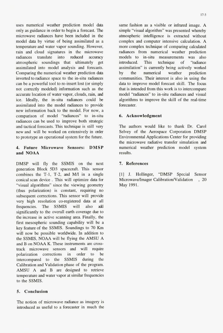
uses numerical weather prediction model data only as guidance in order to begin a forecast. ?he microwave radiances have been included in the model data by virtue of being assimilated as a temperature and water vapor sounding. However, rain and cloud signatures in the microwave radiances translate into reduced accu1~1cy atmospheric soundings that ultimately get assimilated into model analysis and forecasts. Comparing the numerical weather predichon dab inverted to radiance space to the in-situ radianm can be a powerful tool to re-insert lost (or simply not correctly modeled) information such as the accurate location of water vapor, clouds, rain, and ice. Ideally, the in-situ radiances could be assimilated into the model radiances to provide new information back to the model. For now, a comparison of model “radiances” to in-situ radiances can be used to improve both strategic and tactical forecasts. This technique is still very new and will be worked on extensively in der
-to prototype an operational system for the future.
4. Future Microwave Sensors: DMSP and NOAA
DMSP will fly the SSMIS on the next generation Block 5D3 spacecraft. This sensor combines the T-1, T-2, and Mn in a single conical scan device . ms will optimize data for “visual algorithms” since the viewing geometry (thus polarization) is constant, requiring no subsequent corrections. Ths sensor will provide
- very high resolution CO-registered data at all frequencies. The SSMIS will also d significantly to the overall earth coverage due to the increase in active scanrung area. Finally, the f m t mesospheric sounding capability will be a key feature of the SSMIS. Soundings to 70 Km will now be possible worldwide. In addition to the SSMIS, NOAA will be flying the AMSU A and B on NOAA K These instruments are cross- track microwave sensors and will r e q m polarization corrections in order to be intercompared to the SSMIS during the Calibration and Validation phase of the program. AMSU A and B are designed to retrieve temperature and water vapor at similar frequencies to the SSMIS.
5. Conclusion
The notion of microwave radiance as imagery is introduced as useful to a forecaster in much the
17-3
same fashion as a visible or infmed image. A simple “visual algorithm” was presented whereby atmospheric intelligence is extracted without complex and computer intensive calculation. A more complex technique of comparing calculated radiances from numerical weather prediction models to in-situ measurements was also in!mduced. This technique of “radiance assimilation” is currently being actively worked by the numerical weather prediction communities. Their interest is also in using the data to improve model forecast skill. The focus that is intended from this work is to intercompare model “radiances” to in-situ radiances and visual algorithms to improve the skill of the real-time forecaster.
6. Acknowledgment
The authors would like to thank Dr. Carol Selvey of the Aerospace Corporation DMSP Environmental Applications Center for providing the microwave radiative transfer simulation ad numerical weather prediction model system results.
7. References
[l] J. Hollinger, “DMSP Special Sensor MicrowavelImager Calibratioflalidation , 20 May 1991.
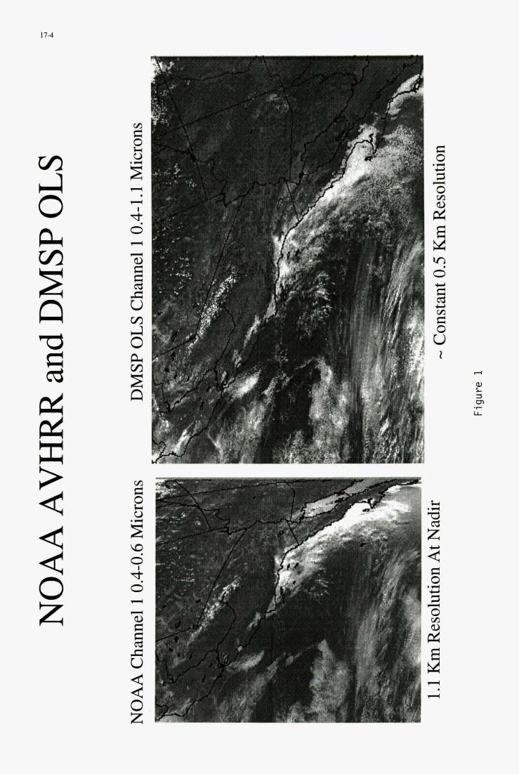
I 7-4
v3 4 0 L v3 E n
d
4 4 4 0 z
5 c., m c 0 I \
i -
E 0 .rl
4 4
0) L m LL
a .I-
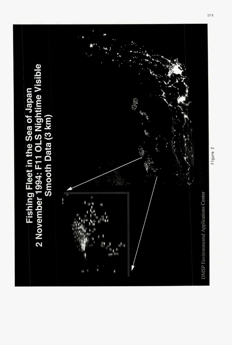
I 17-5
Q)
P U)
I
.I .-
?"
I
r - - - - r
L
n
%
I - -
- ..
. -
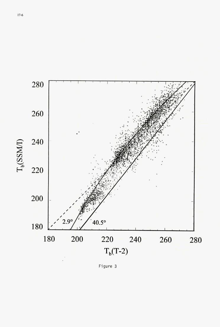
17-6
280
260
200
180
.
180 200 220 240 260 280 TO-2)
Figure 3
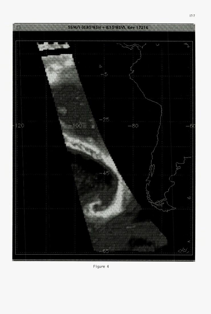
17-7
. . . . .
. . . . .
. .
2
. .
, . . . , . .
t* i
. .
. .
. . . . ,
. . . . . . -
1:
. . . . . .
. . . . . - E
. . .
4:
Figure 4
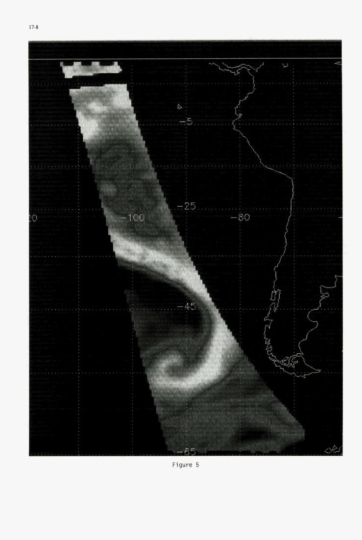
17-8
. . . 0
. . .
. . .
I-
. . . . .
. . . . .
1 . . . . . . . . . . . . . . . . . . . . . . . . . . . . . . . . . . . . . . . . . . . . . . . . . I . . . . is
. . . . . . . . .
. . . . . . . . .
. . . . . . . . .
. . . . . . , .
. . . . . .
. . . .
. . . .
. . . .
. . . . . . . .
I Figure 5
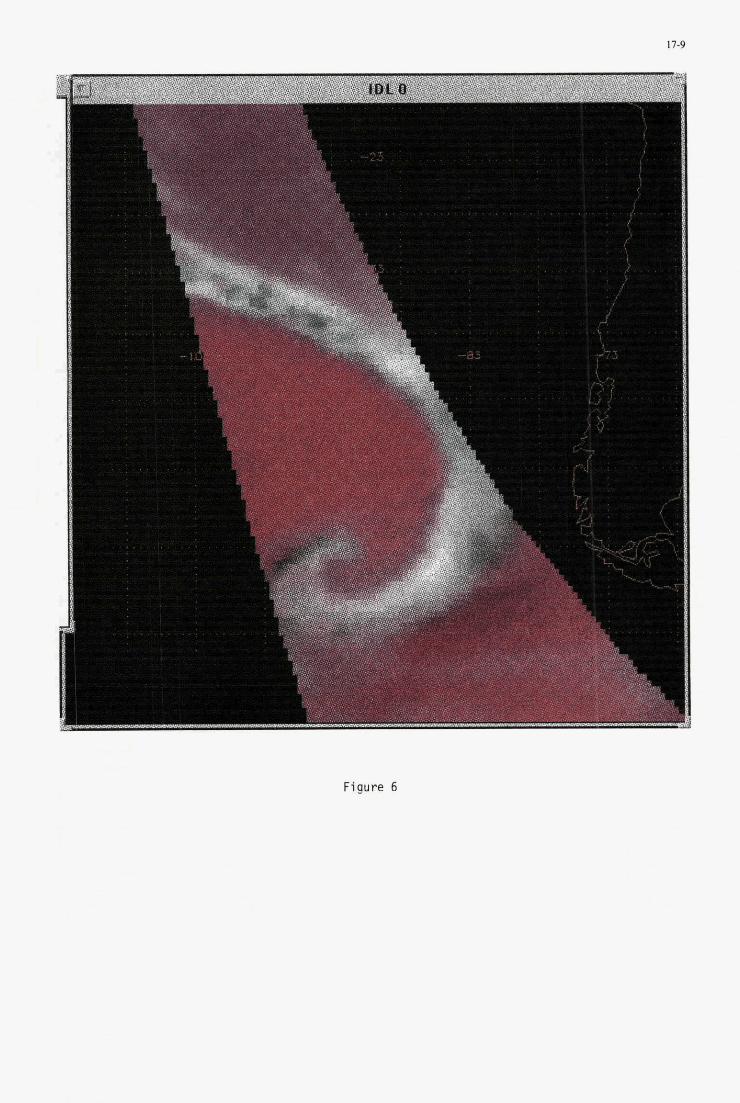
r c., I q
. . . . . . . . . . . . . . . . . . . .
. . . . . . , . . . . . . , . . . . . -83
17-9
!
. . . . . . . . . . . . . . . . .
, , . .
Figure 6
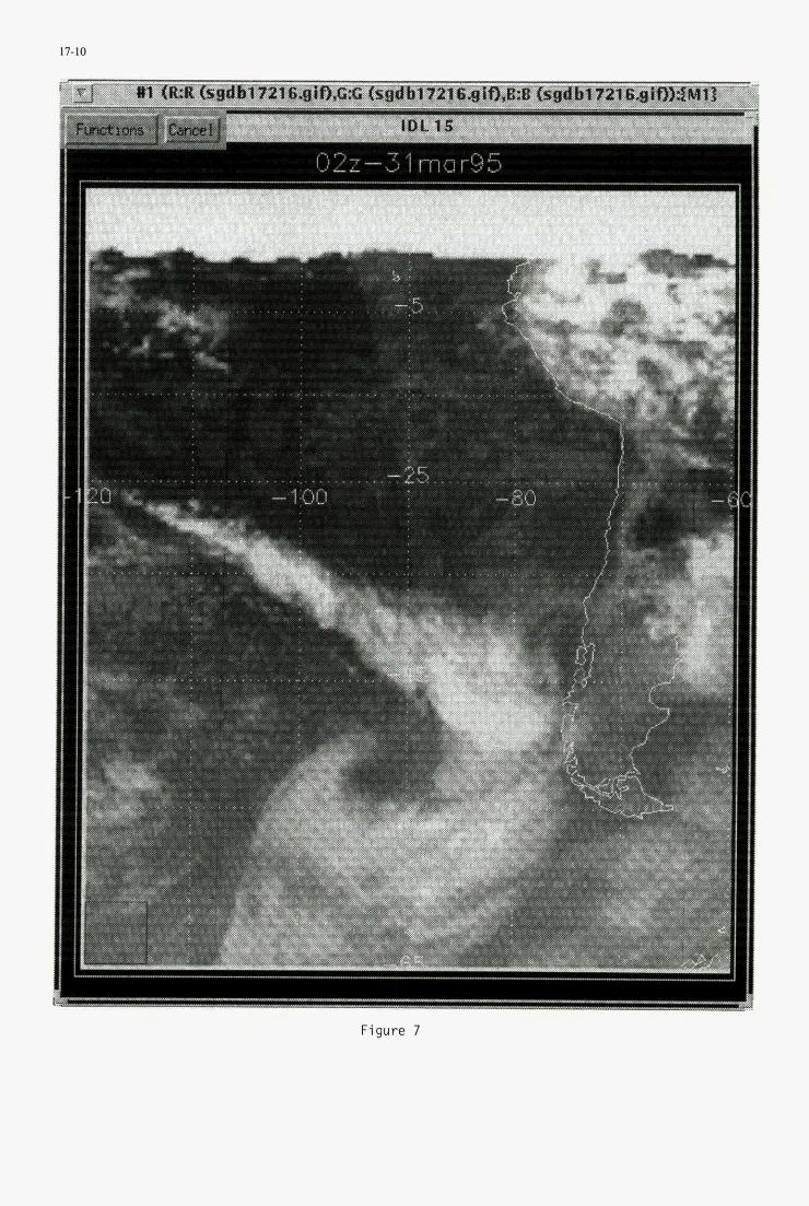
17-10
02z-31 mar95
11-81
Figure 7
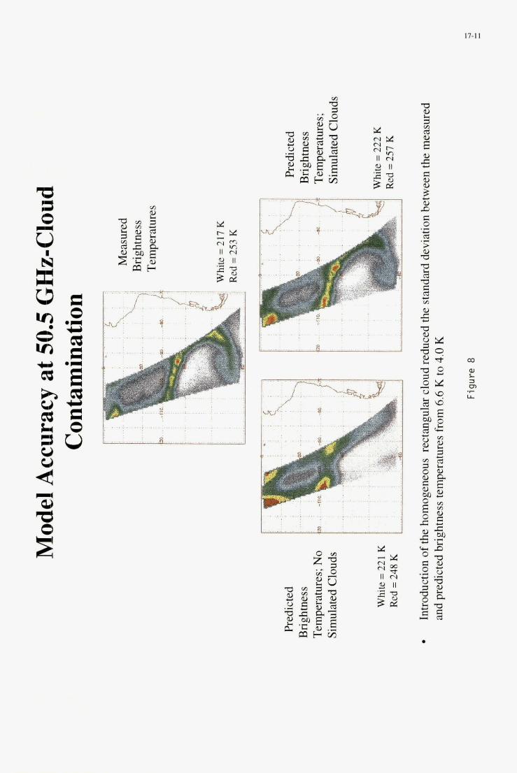
.- . .
...
. . ................................................ . . . , . ..................................................... . .
.. . . . . .
. . . . . . . . . . . . . . . . . . . . . . . . . . . . . r.;~ : ..:I e . . . ; ~ . . :
~
. . . . . . . . . . . . . . .
.......... ~ . . . . . . . . . . . . . . . . . . . . . . . .
.

18-1
SMALL METEOROLOGICAL SATELLITES FOR NATO MILITARY OPERATIONS
D. P. Duclos R. G. Feddes
G. E. Gurevich
THE AEROSPACE CORPORATION 2350 East El Segundo Blvd. El Segundo, CA 90245-4691
U S A
ABSTRACT The planning and effectiveness of military operations can often be greatly enhanced by timely meteorological information. This information is particularly important during rapidly changing weather conditions and can be critical to the success of military operations in a dynamic tactical environment. Due to the ever increasing pace of modern high technology warfare, the revisit time of low orbit meteorological satellites is inadequate to provide the war fighter with timely weather data.
Continuous and timely theater weather information can be obtained from sensors on geostationary satellites which are in a position to observe a particular theater of operations. Continuous monitoring also provides the capability to animate successive frames of data. This technique has been shown to be a powerful tool to interpret meteorological information. While this concept is not new, current meteorological satellites in geostationary orbit are not available to provide continuous coverage. In addition to improving the timeliness and accuracy of environmental information for operations planning, weather data could be provided in near-real-time to troops in the field and potentially to the aircraft cockpit.
This study focused on the concept of small geosynchronous satellites to meet the need for continuous cloud imagery including longitudinal movement to optimize coverage over given theaters of operations. Requirements for the satellite were investigated and the necessary sensor parameters identified. Based on these requirements, a number of sensors of varying capabilities were designed and conceptual
designs for spacecraft compatible with these sensors were developed. Data communication to operational forces was also explored. Finally, applicable launch vehicles were identified and costs for the sensors, satellites, and launch vehicles, were estimated.
It was concluded that sensor and small satellite technology is sufficiently advanced to provide NATO military forces near-real-time cloud imagery at a relatively modest cost.
INTRODUCTION Planning and effectiveness across the spectrum of military operations can be greatly enhanced by timely, usable, and accurate weather information.’ One of the tools military meteorologists and oceanographers use to gather this information, especially from data-denied areas, is the weather satellite. The current constellation of weather satellites in low earth orbit, however, cannot continuously observe the battlespace environment, forcing military meteorologists and oceanographers to provide short term forecasts of up to six hours with no updated satellite information. While these forecasts are adequate for many applications, forecasting rapidly changing geophysical parameters continues to be a major challenge as illustrated in the following examples.
Cloud Fields: Many DoD smart weapons require line-of-sight visibility to target laser guided munitions. The attacking aircraft must continue to illuminate the target as the bomb homes in on the reflected laser energy. If unforecast clouds are in the target area, the smart weapon could lose lock-on and miss the target, perhaps causing unacceptable collateral damage. If up-to-date cloud information were available,
Paper presented at the AGARD MSP 51h Symposium on “Space Systems as Contributors to the NATO Defence Mission”, held in Cannes, France, 3-6 June 1996, and published in CP-580.
18-2
the attacking formation would gain tremendous flexibility, choosing while enroute the best ingress corridor at the best altitude for the weapon load to avoid the clouds or moving to an alternate target much earlier in the strike mission. Operation Desert Storm is a case-in- point. Attack aircraft sorties often had to fly multiple hours to reach targets, sometimes finding the area obscured by unforecast weather, then proceeding to an alternate to find it also obscured, and then facing a decision to rendezvous with a tanker (if available) or return to base.
Low Level Winds: A coordinated strike on a series of targets which are closely spaced requires close attention to the wind direction and speed in the target complex. If the first target is upwind of the next in a series of attacks, smoke and dust from the first strike can obscure the next strike’s targets. The capability of a continuous “bird’s eye” view of the weather in the target complex once again adds tremendous flexibility to the attacking force allowing them to switch to alternate lay down strategies while enroute.
Diurnal Phenomena: Since low earth orbiting weather satellites visit the same spot of the earth at the same time every day, some diurnal phenomena which affect the battlespace may never be observed or forecast until the strike force encounters it. Fog in the littoral zone, for example, may not be discernible on an early morning low earth orbit pass, and can “burn off’ before the late morning pass, forcing, at the very least, an abrupt change in tactics of an attacking force.
Hazardous Weather: Squall lines, severe convective weather, amount and type of precipitation, tropical cyclone movement and extent of damaging winds, are all significant weather phenomena which impact military operations and would benefit from continuous observation.
Continuous and timely theater weather information can be obtained from sensors on geosynchronous satellites which can observe a particular theater of operation between 60 degrees latitude north and south. An example of this type of satellite is the GOES which carries a number of instruments for meteorological observation. However, this type of satellite is large, costly, and is designed to provide data for global weather forecasts. The GOES, for example, can scan the earth disc approximately
every 30 minutes (although the capability to rapidly scan a small area does exist).
A geosynchronous satellite dedicated to military operations could provide continuous high resolution weather monitoring for any theater of interest. This satellite, linked to a suitable military communication system, could provide near-real-time cloud images to military forces. In addition to improving the timeliness and availability of data for the planning function, this data could be available to support a variety of tactical scenarios, possibly including the transmission of cloud data directly in the cockpit. Continuous monitoring also provides the capability to provide qualitative data for animation, which is a powerful tool to quantitatively interpret meteorological information.
The objective of this study was to develop small geosynchronous satellite concepts which would provide continuous high resolution cloud imagery that could be downlinked in near-real- time to operational military forces. The study focused on small, relatively simple sensor concepts that would provide only cloud imagery for specific military theaters and would result in a satellite that is much lower in cost than current large, complex geosynchronous meteorological satellites. Optimized coverage for any given theater of operations would be provided through longitudinal movement of the satellite and other theaters on the observable earth disc would be covered through sequential operation of the sensor.
The paper describes a set of assumed requirements presenting three sensor options, including their corresponding design and performance, discusses communications with military forces, and describes the candidate small satellite designs. Finally, the paper presents the availability and type of launch vehicles required, and the resulting cost estimates for the satellites and launch vehicles.
ASSUMED REOUIREMENTS The requirements for this study can be divided into those for the sensor, communications, spacecraft, and launch vehicle. The most critical requirements are described here.
There are six data and corresponding sensor requirements: 1) The imaged area should be comparable to that of a military theater of operation. The corresponding sensor requirement chosen was a field of view from
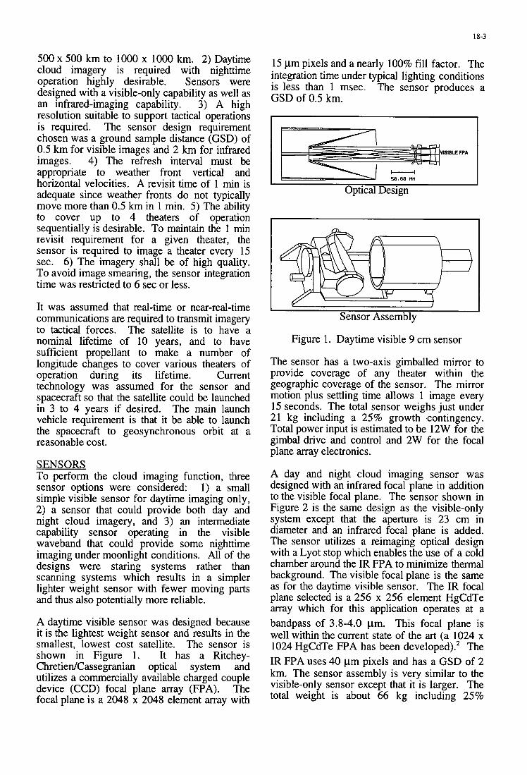
18-3
500 x 500 km to 1000 x 1000 km. 2) Daytime cloud imagery is required with nighttime operation highly desirable. Sensors were designed with a visible-only capability as well as an infrared-imaging capability. 3) A high resolution suitable to support tactical operations is required. The sensor design requirement chosen was a ground sample distance (GSD) of 0.5 km for visible images and 2 km for infrared images. 4) The refresh interval must be appropriate to weather front vertical and horizontal velocities. A revisit time of 1 min is adequate since weather fronts do not typically move more than 0.5 km in 1 min. 5 ) The ability to cover up to 4 theaters of operation sequentially is desirable. To maintain the 1 min revisit requirement for a given theater, the sensor is required to image a theater every 15 sec. 6) The imagery shall be of high quality. To avoid image smearing, the sensor integration time was restricted to 6 sec or less.
It was assumed that real-time or near-real-time communications are required to transmit imagery to tactical forces. The satellite is to have a nominal lifetime of 10 years, and to have sufficient propellant to make a number of longitude changes to cover various theaters of operation during its lifetime. Current technology was assumed for the sensor and spacecraft so that the satellite could be launched in 3 to 4 years if desired. The main launch vehicle requirement is that it be able to launch the spacecraft to geosynchronous orbit at a reasonable cost.
SENSORS To perform the cloud imaging function, three sensor options were considered: 1 ) a small simple visible sensor for daytime imaging only, 2) a sensor that could provide both day and night cloud imagery, and 3) an intermediate capability sensor operating in the visible waveband that could provide some nighttime imaging under moonlight conditions. All of the designs were staring systems rather than scanning systems which results in a simpler lighter weight sensor with fewer moving parts and thus also potentially more reliable.
A daytime visible sensor was designed because it is the lightest weight sensor and results in the smallest, lowest cost satellite. The sensor is shown in Figure 1. It has a Ritchey- ChretiedCassegranian optical system and utilizes a commercially available charged couple device (CCD) focal plane array (FPA). The focal plane is a 2048 x 2048 element array with
15 pm pixels and a nearly 100% fill factor. The integration time under typical lighting conditions is less than 1 msec. The sensor produces a GSD of 0.5 km.
VlSlBLE FPA
I ’ 50.80 tit i
Optical Design
I
I 1
Sensor Assembly
Figure 1. Daytime visible 9 cm sensor
The sensor has a two-axis gimballed mirror to provide coverage of any theater within the geographic coverage of the sensor. The mirror motion plus settling time allows 1 image every 15 seconds. The total sensor weighs just under 21 kg including a 25% growth contingency. Total power input is estimated to be 12W for the gimbal drive and control and 2W for the focal plane array electronics.
A day and night cloud imaging sensor was designed with an infrared focal plane in addition to the visible focal plane. The sensor shown in Figure 2 is the same design as the visible-only system except that the aperture is 23 cm in diameter and an infrared focal plane is added. The sensor utilizes a reimaging optical design with a Lyot stop which enables the use of a cold chamber around the IR FPA to minimize thermal background. The visible focal plane is the same as for the daytime visible sensor. The IR focal plane selected is a 256 x 256 element HgCdTe array which for this application operates at a bandpass of 3.8-4.0 pm. This focal plane is well within the current state of the art (a 1024 x 1024 HgCdTe FPA has been developed).* The IR FPA uses 40 pm pixels and has a GSD of 2 km. The sensor assembly is very similar to the visible-only sensor except that it is larger. The total weight is about 66 kg including 25%
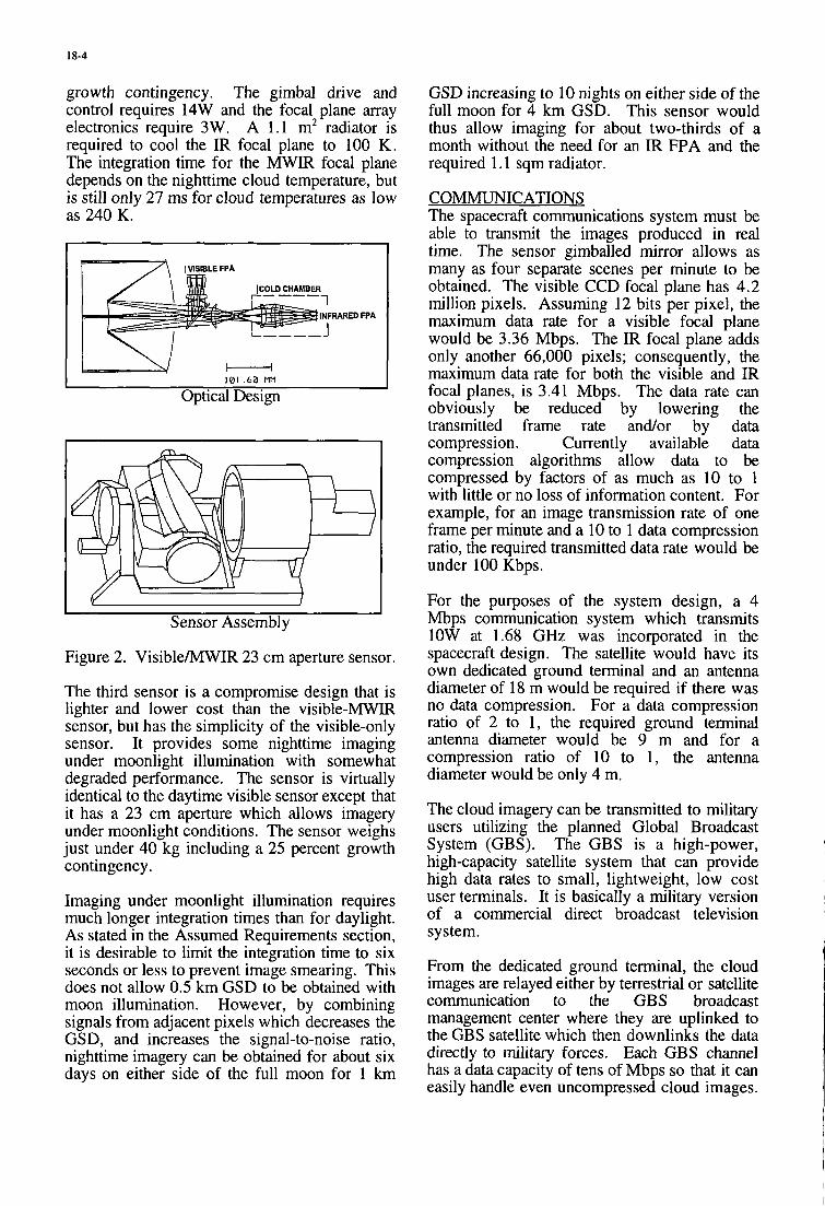
18-4
growth contingency. The gimbal drive and control requires 14W and the focal plane array electronics require 3W. A 1.1 m2 radiator is required to cool the IR focal plane to 100 K. The integration time for the MWIR focal plane depends on the nighttime cloud temperature, but is still only 27 ms for cloud temperatures as low as 240 K.
H I I01 . 6 0 MM I
Optical Design
~~ ~~ ~~ ~
Sensor Assembly
Figure 2. VisibleMWIR 23 cm aperture sensor.
The third sensor is a compromise design that is lighter and lower cost than the visible-MWIR sensor, but has the simplicity of the visible-only sensor. It provides some nighttime imaging under moonlight illumination with somewhat degraded performance. The sensor is virtually identical to the daytime visible sensor except that it has a 23 cm aperture which allows imagery under moonlight conditions. The sensor weighs just under 40 kg including a 25 percent growth contingency.
Imaging under moonlight illumination requires much longer integration times than for daylight. As stated in the Assumed Requirements section, it is desirable to limit the integration time to six seconds or less to prevent image smearing. This does not allow 0.5 km GSD to be obtained with moon illumination. However, by combining signals from adjacent pixels which decreases the GSD, and increases the signal-to-noise ratio, nighttime imagery can be obtained for about six days on either side of the full moon for 1 km
GSD increasing to 10 nights on either side of the full moon for 4 km GSD. This sensor would thus allow imaging for about two-thirds of a month without the need for an IR FPA and the required 1.1 sqm radiator.
COMMUNICATIONS The spacecraft communications system must be able to transmit the images produced in real time. The sensor gimballed mirror allows as many as four separate scenes per minute to be obtained. The visible CCD focal plane has 4.2 million pixels. Assuming 12 bits per pixel, the maximum data rate for a visible focal plane would be 3.36 Mbps. The IR focal plane adds only another 66,000 pixels; consequently, the maximum data rate for both the visible and IR focal planes, is 3.41 Mbps. The data rate can obviously be reduced by lowering the transmitted frame rate andor by data compression. Currently available data compression algorithms allow data to be compressed by factors of as much as 10 to 1 with little or no loss of information content. For example, for an image transmission rate of one frame per minute and a 10 to 1 data compression ratio, the required transmitted data rate would be under 100 Kbps.
For the purposes of the system design, a 4 Mbps communication system which transmits 1OW at 1.68 GHz was incorporated in the spacecraft design. The satellite would have its own dedicated ground terminal and an antenna diameter of 18 m would be required if there was no data compression. For a data compression ratio of 2 to 1, the required ground terminal antenna diameter would be 9 m and for a compression ratio of 10 to 1, the antenna diameter would be only 4 m.
The cloud imagery can be transmitted to military users utilizing the planned Global Broadcast System (GBS). The GBS is a high-power, high-capacity satellite system that can provide high data rates to small, lightweight, low cost user terminals. It is basically a military version of a commercial direct broadcast television system.
From the dedicated ground terminal, the cloud images are relayed either by terrestrial or satellite communication to the GBS broadcast management center where they are uplinked to the GBS satellite which then downlinks the data directly to military forces. Each GBS channel has a data capacity of tens of Mbps so that it can easily handle even uncompressed cloud images.
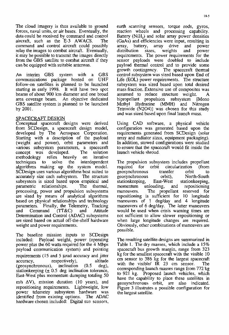
18-5
The cloud imagery is thus available to ground forces, naval units, or air bases. Eventually, the datacould be received by command and control aircraft, such as the E-3 AWACS. The command and control aircraft could possibly relay the images to combat aircraft. Eventually, it may be possible to transmit the images directly from the GBS satellite to combat aircraft if they can be equipped with suitable antennas.
An interim GBS system with a GBS communications package hosted on UHF follow-on satellites is planned to be launched starting in early 1998. It will have two spot beams of about 900 km diameter and one broad area coverage beam. An objective dedicated GBS satellite system is planned to be launched by 2001.
SPACECRAFT DESIGN Conceptual spacecraft designs were derived from SCDesign, a spacecraft design model, developed by The Aerospace Corporation. Starting with a description of the payload (weight and power), orbit parameters and various subsystem parameters, a spacecraft concept was developed. The solution methodology relies heavily on iterative techniques to solve the interdependent algorithms making up the system model. SCDesign uses various algorithms best suited to accurately size each subsystem. The structure subsystem is sized based upon empirical and parametric relationships. The thermal, processing, power and propulsion subsystems are sized by means of analytical algorithms based on physical relationships and technology parameters. Finally, the Telemetry, Tracking and Command (TT'&C) and Attitude Determination and Control (ADAC) subsystems are sized based on actual off-the-shelf hardware weight and power requirements.
The baseline mission inputs to SCDesign included: Payload weight, power (operating power plus the 60 watts required for the 4 Mbps payload communication system) and pointing requirements (1 5 and 5 p a d accuracy and jitter accuracy , respectively), altitude (geosynchronous), inclination (0.5 deg), stationkeeping (+ 0.5 deg inclination tolerance, East-West plus momentum dumping totaling 50 m / s AV), mission duration (10 years), and repositioning requirements. Lightweight, low power telemetry subsystem hardware was identified from existing options. The ADAC hardware chosen included: Digital sun sensors,
earth scanning sensors, torque rods, gyros, reaction wheels and processing capability. Battery (NiH,) and solar array power densities (GaAs) and efficiencies were input, resulting in array, battery, array drive and power distribution sizes, weights and power requirements. The power requirements for the sensor payloads were doubled to include payload thermal control and to provide some growth contingency. The spacecraft thermal control subsystem was sized based upon End of Life (EOL) power requirements. The structure subsystem was sized based upon total desired mass fraction. Extensive use of composites was assumed to reduce structure weight. A bipropellant propulsion subsystem [Mono Methyl Hydrazine (MMH) and Nitrogen Tetroxide (N204)] was chosen for this study and was sized based upon final launch mass.
Using CAD software, a physical vehicle configuration was generated based upon the requirements generated from SCDesign (solar array and radiator sizes, equipment packaging). In addition, stowed configurations were studied to ensure that the spacecraft would fit inside the launch vehicle shroud.
The propulsion subsystem includes propellant required for orbit circularization (from
stationkeeping, East-West stationkeeping, momentum unloading, and repositioning maneuvers. The propellant reserved for repositioning is sufficient for 10 longitude maneuvers of 1 deg/day and 4 longitude maneuvers of 6 deg/day. The latter maneuvers would be used when crisis warning times are not sufficient to allow slower repositioning or when large longitude changes are required. Obviously, other combinations of maneuvers are possible.
geosynchronous transfer orbit to geosynchronous orbit), North-South
The resulting satellite designs are summarized in Table 1. The dry masses, which include a 15% spacecraft bus growth margin, range from 323 kg for the smallest spacecraft with the visible 10 cm sensor to 386 kg for the largest spacecraft with the visible/ IR 23 cm sensor. The corresponding launch masses range from 772 kg to 921 kg. Proposed launch vehicles, which have the capability to place these satellites in geosynchronous orbit, are also indicated. Figure 3 illustrates a possible configuration for the largest satellite.
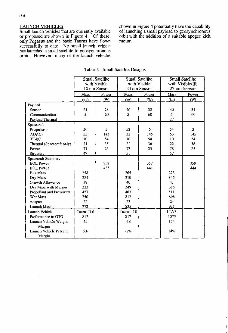
18-6
52 53 10 21 77 51
265 310 40
349 463 812 23
835 Taurus 11-0
817 -18
-2%
LAUNCH VEHICLES Small launch vehicles that are currently available or proposed are shown in Figure 4. Of these, only Pegasus and the basic Taurus have flown successfully to date. No small launch vehicle has launched a small satellite to geosynchronous orbit. However, many of the launch vehicles
shown in Figure 4 potentially have the capability of launching a small payload to geosynchronous orbit with the addition of a suitable apogee kick motor.
5 145 54 36 25
357 44 1
Table 1. Small Satellite Designs
Payload Sensor Communication Payload Thermal
Spacecraft Propulsion ADACS ?T&C Thermal (Spacecraft only) Power Structure
EOL Power BOL Power Bus Mass Dry Mass Growth Allowance Dry Mass with Margin Propellant and Pressurant Wet Mass Adapter Launch Mass
Launch Vehicle Performance to GTO Launch Vehicle Weight
Launch Vehicle Percent
Spacecraft Summary
Margin
Margin
Small Satellite with Visible 10 cm Sensor
Mass
0 21 5
50 53 10 21 77 47
258 284 39
323 427 750 22
772 Taurus II-0
817 45
6%
Power
L 28 60
5 145 54 35 25
352 435
Small Satellite with Visible
23 cm Sensor Power
t
Small Satellite with Visible/IR 23 cm Sensor
Mass
0 40 5 27
54 53 10 22 78 57
273 345 41 386 51 1 896 24
92 1 LLV3 1075 154
14%
Power
0 34 60
5 145 54 36 25
359 444
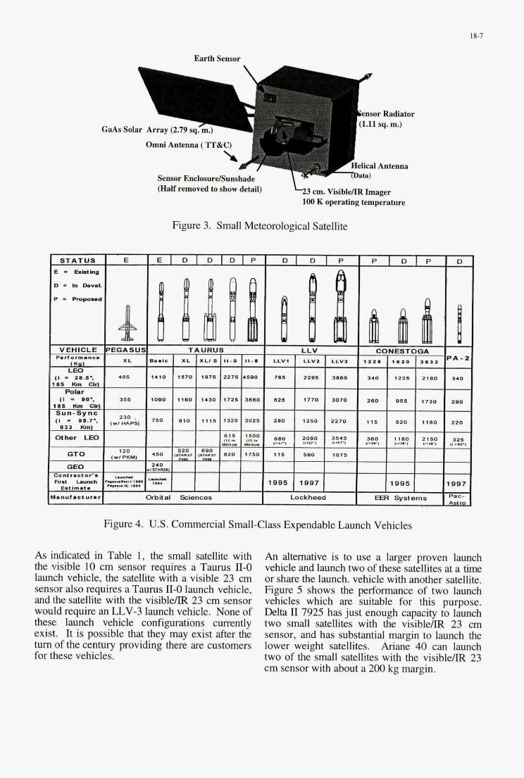
1 8-7
GaAs Sol
Earth Sensor
emor Radiator (1.11 sq. m.)
Omni Antenna (TT&C)
Helical Antenna Sensor EnclosurdSumhade
b 3 cm. VisibldR Imager (Half removed to show detail) 100 K operating temperature
Figure 3. Small Meteorological Satellite
Figure 4. U.S. Commercial Small-Class Expendable Launch Vehicles
As indicated in Table 1, the small satellite with the visible 10 cm sensor requires a Taurus 11-0 launch vehicle, the satellite with a visible 23 cm sensor also requires a Taurus 11-0 launch vehicle, and the satellite with the visible/IR 23 cm sensor would require an LLV-3 launch vehicle. None of these launch vehicle configurations currently exist. It is possible that they may exist after the turn of the century providing there are customers for these vehicles.
An alternative is to use a larger proven launch vehicle and launch two of these satellites at a time or share the launch. vehicle with another satellite. Figure 5 shows the performance of two launch vehicles which are suitable for this purpose. Delta I1 7925 has just enough capacity to launch two small satellites with the visibleAR 23 cm sensor, and has substantial margin to launch the lower weight satellites. Ariane 40 can launch two of the small satellites with the visibleAR 23 cm sensor with about a 200 kg margin.
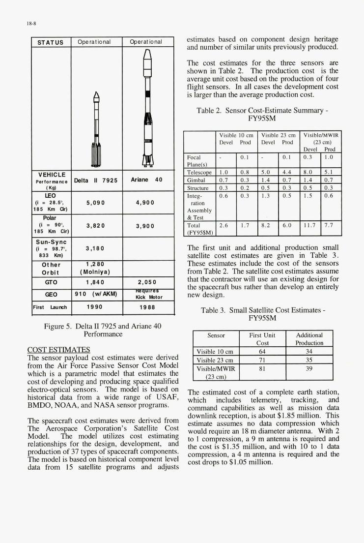
18-8
STATUS
VEHICLE Pertor mance
I I 2 8 3 , 85 Km or)
Polar (I E 900,
85 Km cir)
Sun-Sync [I = W . P , 833 Km)
Other Orbit GTO
GEO
lmt Launch
ODe rat io nal
Mite II 7925
5 ,090
3 ,820
3,180
1,280 I Molnlva) . .
1,840
310 (w/AKM)
1990
Ariana 40
4,900
3,900
2,050
Kick Motor
1988
Figure 5. Delta II7925 and Ariane 40 Performance
COST ESTIMATES The sensor payload cost estimates were derived from the Air Force Passive Sensor Cost Model which is a parametric model that estimates the cost of developing and producing space qualified electro-optical sensors. The model is based on historical data from a wide range of USAF, BMDO, NOAA, and NASA sensor programs.
The spacecraft cost estimates were derived from The Aerospace Corporation’s Satellite Cost Model. The model utilizes cost estimating relationships for the design, development, and production of 37 types of spacecraft components. The model is based on historical component level data from 15 satellite programs and adjusts
estimates based on component design heritage and number of similar units previously produced.
The cost estimates for the three sensors are shown in Table 2. The production cost is the average unit cost based on the production of four flight sensors. In all cases the development cost is larger than the average production cost.
Table 2. Sensor Cost-Estimate Summary - FY95$M
The first unit and additional production small satellite cost estimates are given in Table 3. These estimates include the cost of the sensors from Table 2. The satellite cost estimates assume that the contractor will use an existing design for the spacecraft bus rather than develop an entirely new design.
Table 3. Small Satellite Cost Estimates - Ey95$M
Sensor First Unit Additional Production
Visible 10 cm Visible 23 cm VisiblelMWIR
23 cm
The estimated cost of a complete earth station, which includes telemetry, tracking, and command capabilities as well as mission data downlink reception, is about $1.85 million. This estimate assumes no data compression which would require an 18 m diameter antenna. With 2 to 1 compression, a 9 m antenna is required and the cost is $1.35 million, and with 10 to 1 data compression, a 4 m antenna is required and the cost drops to $1.05 million.
18-9
The cost of an extended capability Taurus or the Lockheed LLV-3 would probably be of the order of $30 million or more. This cost should be
Aerospace C31 in Coming Years, Published November, 1995.
considered a very rough estimate since these L J. Kozlowski, et al, ~ g 2 . 5 ~ ~ PACE-I vehicles exist only as preliminary designs. On HgCdTe loB 1024 for Infrared the Other hand, the Of the 7925 Or Astronomy,” SPIE Proceedings 2268, 1994, p. Ariane 40 launch vehicle is about $55 million.
2
zcz J J J . Since these vehicles can launch two satellites, the
launch cost per satellite would probably be less than if the smaller launch vehicles were used.
SUhtMARYKONCLUSIONS Electro-optical sensors and small satellite designs were developed to provide both day and night high resolution weather imagery from geosynchronous orbit. Real time dissemination of this imagery to military users is possible using the Global Broadcast System. The cost of the system is modest especially compared with the cost of large geosynchronous satellites.
Launch is a potential problem. No small launch vehicle has yet launched a small satellite to geosynchronous orbit, and it is not known if one will be available in the foreseeable future. However, two of the satellite designs from this study can be launched on a Delta II7925, or an Ariane 40 launch vehicle or alternatively, the launch vehicle can be shared with another satellite.
Another possible option, not investigated in this study, is to place a sensor on a large geosynchronous satellite, such as a communications satellite. This may be a feasible option for the visible 9 cm sensor which weighs only 21 kg.
ACKNOWLEDGMENTS The authors would like to acknowledge the contributions of the late R. J. Chambers who developed the sensor designs, G. L. Lui and R. M. Garcia who developed the spacecraft communications system, E. L. Burgess who developed the cost estimates, and S. C. Morrison who provided the launch vehicle performance data. The authors are also grateful to R. F. Coleman for his comments and suggestions, to G. C. Aufderhaar for his contributions on the military utility of the concept, and to R. B. Schooler for providing data on FPAs. D. W. Warren, L. A. Selzer, and R. W. Reid read the draft and made useful suggestions.
REFERENCES 1. J. S. Bohlson and R. W. Reid. “A Weather Forecast Utility Model for Milib& Missions,” AGARD Conference Proceedings No. 557,

21-18
implications for the payload weight (and cost) of possible sensor designs. The potential for significant weight savings exists if the current SSGM is found to be too conservative in its cloud scatter model. On the other hand, if in fact the model turns out to underestimate the severity of the solar scatter problem, a conservative sensor design approach (i.e., smaller footprints) along with more sophisticated processing will be required to mitigate the system impact.
ACKNOWLEDGEMENTS We tbank Dr. T.S. Lomheim for many useful discussions and for the payload weight information used in this paper. We also tba& Dr. I. Shanks of PRA for providing technical insights into the SSGM modeling results and uncertainties
REFERENCES
1. Generation Model Release 4.0 User’s Manual”, 1992.
Photon Research Associates, Inc., “Synthetic Scene
2. Cota, S. A., Kalman, L. S and Keller, R. A., “Advanced Sensor Simulation Capability”, Signal & Image Processing Systems Performance Evaluation, SPlE Vol. 1310, pp.134- 149, 1990.
3. Robinson. I.S., Rudy, D.J. and Gonzalez. M.M. ”Frequency of Cloud Cover at Altitude: Implications for Surveillance Systems“, Aerospace Technical Report, A m - 94 (8019)-1. 1994.
4. Wylie, D.P., Menzel, W.P.. Woolf, H.M. and Strabala. K.L,”Four Years of Global C ims Cloud Statistics Using HIRS”, Journal of Climate Vol. VII, No. 12, 1994.
5. Backgrounds from 2.65 to 2.95 microns”, A.D. Little Inc.,Report No.70505F, January 1970.
6. Futterman. W.I. and Benson, R.S., “Infrared (IR) Scene Generator and Analytic Statistical Modeling”, Modem Utilization of IR Technology VU, S P E Vol. 253, pp.107- 121. 1980.
7. Casey, E.J. and Kafesjian. S.L., “Infrared Sensor Modeling for Improved System Design”. Infrared Imaging Systems: Design, Analysis, Modeling, and Testing VII. SPlE Vol. 2743, 1996.
Espinola, R.P., “Spatial and Spectral Properties of Cloud
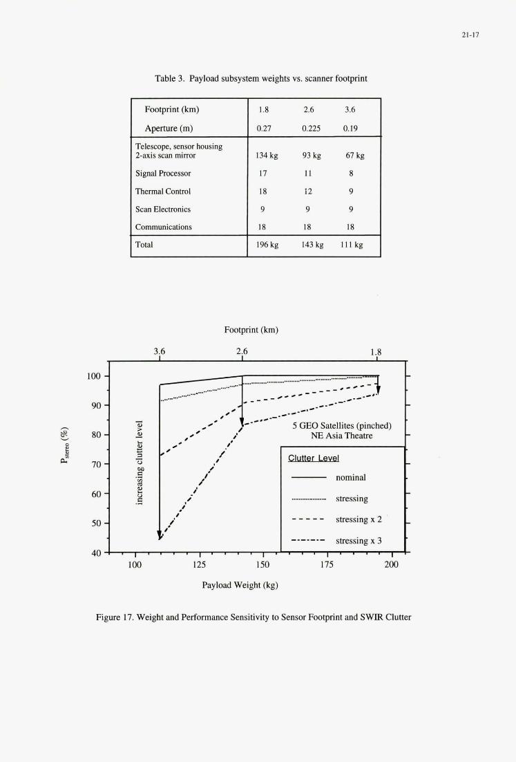
21-17
Table 3. Payload subsystem weights vs. scanner footprint
Footprint (km)
Aperture (m)
Telescope, sensor housing Z-axis scan mirror
Signal Processor
Thermal Control
Scan Electronics
Communications
Total I 196kg 143kg l l l k g I
8
i -/ / .'
4
i
Footprint (km)
3.6 2.6 1.8 -
._..... .-e--
_.---I
,__..... .- ....... 100 -
.-.-- 90 - - #'
B 80 - s
a i 2 I
0 70 - .-
C 60 - .-
so 1 40
100 125 150
5 GEO Satellites @inched) NE Asia Theatre
nominal t t stressing
t stressing x 2 - - - - - stressing x 3
175 200
-.-.-.- . . . . . . . . . t
Payload Weight (kg)
Figure 17. Weight and Performance Sensitivity to Sensor Footprint and SWIR Clutter
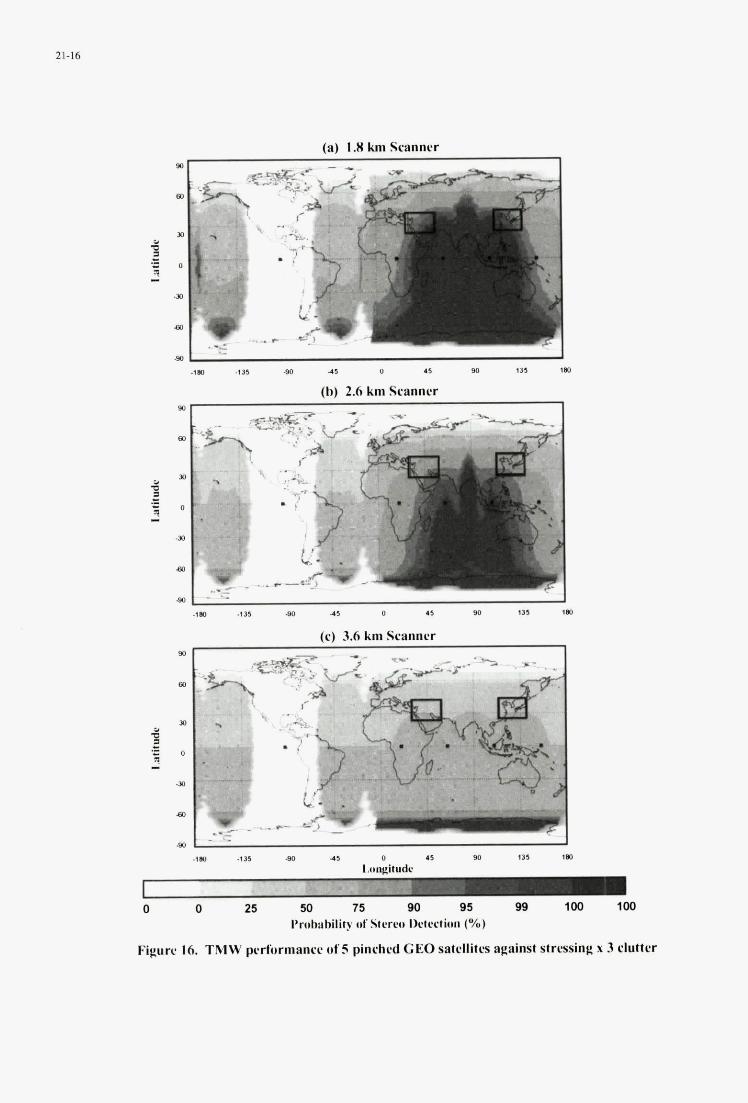
21-16
(a) 1.8 km S w m c r i
~. . ._ . . .'.. , ' . .
. . .
I " . , . . , .
. , .
-la .I35 80 41 0 .I 90 115 t a
(h) 2.6 km Scanner
1 -lm -1 3% 00 4 5 0 .5 90 135 1m
(c) 3.6 km Scanner 90
D
2 B o ?( -
Jo
a0
90
.im 0 45 I35 ,a
0 0 25 50 75 90 95 BB 100 100 Pnihahilily of Stcrcs llctc!ction (Yo)
Figurc 16. TMW pcrformancc of 5 pinched GEO satcllitls against strrsing x 3 clutter
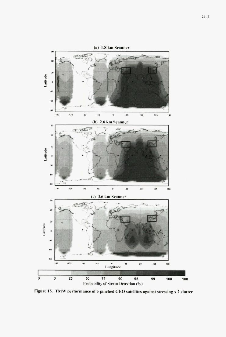
21-15
(a) I .# km Scanner
(b) 2.6 km Scanner m
Y ,.
(c) 3.6 km Scanner m .
0
Figuw IS. TMW pcrfunnancr. ufS pinchrd CEO satcllitrs against sfrrssing x 2 clutter
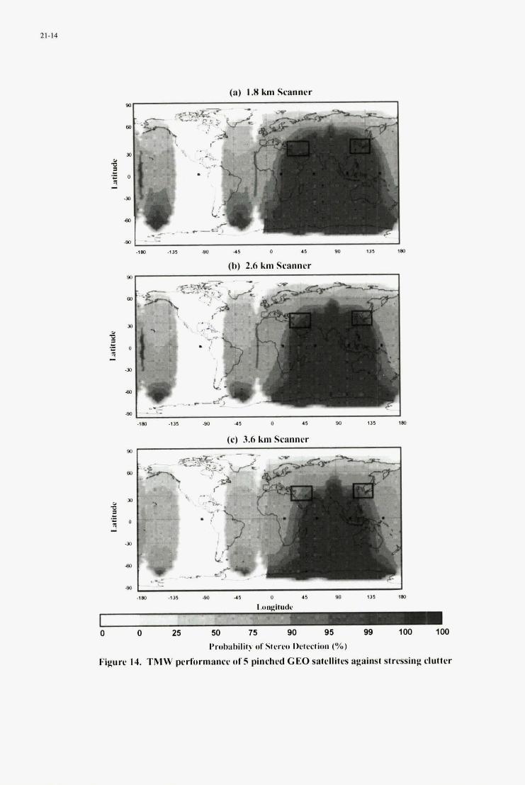
I 21-14
(a) 1.8 km Scanner
L
_.1
(h) 2.6 km Scannrr
I .,m .,n -so 4 5 0 43 SO I35 tm
(c) 3.6 km Scanner
4 m io35 8 4 3 0 I 5 w 135 180
0 0 25 50 73 90 95 99 1w 100
Pnbbirhility of Stcrw lktcctiun (%)
Figure 14. TMW performance of 5 pinched CEO satcllitus against strissing clutter
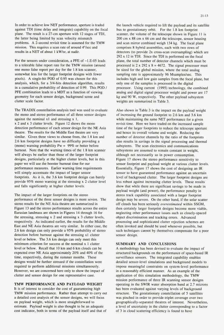
21-13
the launch vehicle required to lift the payload and its satellite bus to geostationary orbit. scanner, the volume of the telescope shown in Figure 1 I is 200 cm x 88 cm x 66 cm and the telescope. sensor housing and scan mirror combined weigh 134 kg. The focal plane comprises 8 hybrid assemblies, each with two rows of detectors (to provide 2x cross-scan oversampling) which are 292 x 12 in TDI. Since the TDI is performed on the focal plane, the total number of detector channels which must be processed is 2 x 292 x 8 = 4672. The signal processor must be sized for the global mission, where the total analog sampling rate is approximately 96 Msampledsec. This includes high and low gain samples from the focal plane, but only one of the samples is processed in the digital processor. Using current (1995) technology. the combined analog and digital signal processor weight and power are 17 kg and 90 W. respectively. The other payload subsystem weights are summarized in Table 3.
For the 1.8 km footprint In order to achieve low NET performance, aperture is traded against TDI (time delay and integrate) capability on the focal plane. The result is a 27-cm aperture with 12 stages of TDI, the latter being limited by scan velocity mismatch problems. A 2-second revisit time is assumed for the TMW mission. This requires a scan rate of around 4'Isec and results in a NET of about 1 kWIsr, at nadir.
For the sensors under consideration, a PFE of -1.E-05 leads to a tolerable false repon rate for the TMW mission (around one mono false report per day for the 1.8 km scanner, somewhat less for the larger footprint designs with fewer pixels). A single-hit POD of 0.95 was chosen for this analysis, which, for a 3/4-hits detection algorithm, results in a cumulative probability of detection of 0.99. This POD I P E combination leads to a MDT as a function of viewing geometry for each sensor design, background scene and clutter scale factor.
The TRADIX constellation analysis tool was used to evaluate the mono and stereo performance of all three sensor designs against the nominal X I and stressing x 1, x 2 and x 3 clutter levels. Figure I2 shows the mono detection performance of each sensor design for the NE Asia theatre. The results for the Middle East theatre are very similar. Given three views to choose from, the 1.8 km and 2.6 km footprint designs have no difficulty providing a (mono) warning probability Pw = 99% or better before burnout. Note that the warning times of the 1.8 km scanner will always be earlier than those of the larger footprint designs, particularly at the higher clutter levels, but in this paper we will use the booster burnout time for our performance measures. Earlier warning time requirements will simply accentuate the impact of larger sensor footprints. As it is, the 3.6 km footprint design can barely provide 95% mono warning at the stressing x 2 clutter level and falls significantly at higher clutter levels.
The impact of the larger footprints on the stereo performance of the three sensor designs is more severe. The stereo results for the NE Asia theatre are summarized in Figure 13 and the stereo Performance results across the entire Eurasian landmass are shown in Figures 14 through 16 for the stressing, stressing x 2 and stressing x 3 clutter levels, respectively. As indicated earlier, the results for the Middle East and NE Asia theatres are very similar. In either case, the 2.6 km design can only provide a 95% probability of stereo detection before burnout against the stressing XI clutter level o r below. The 3.6 km design can only meet this minimum criterion for success at the nominal x 1 clutter level or below. Recall that I O km and 6 km clouds can be expected over NE Asia approximately 20% and 40% of the time, respectively. during the summer months. These designs would be further stressed if the constellation were required to perform additional missions simultaneously. However, we are concerned here only to show the impact of clutter and sensor design for one representative case.
TMW PERFORMANCE AND PAYLOAD WEIGHT It is of interest to consider the cost of guaranteeing high TMW mission performance. Rather than attempt to carry out a detailed cost analysis of the sensor designs, we will focus on payload weight. which is more straightforward to estimate. Payload weight is also thought to be an adequate cost indicator, both in terms of the payload itself and that of
Also shown in Table 3 is the impact on the payload weight of increasing the ground footprint to 2.6 km and 3.6 km while maintaining the same NET performance for a given revisit time. Here we have traded on the increased sample time of the larger footprints to reduce the telescope aperture and hence its overall volume and weight. Reducing the number of detector channels by the ratio of the footprints also results in savings in the signal processing and thermal subsytems. The scan electronics and communications subsystems are assumed to remain constant in weight, although not necessarily so in power consumption. Figure 17 shows the stereo performance sensitivity to sensor footprint and payload weight at various clutter levels. Essentially, Figure 17 shows the cost of designing an IR sensor to have guaranteed performance against an uncertain level of background clutter. The larger footprint designs are less robust against increasing clutter levels. These results show that while there are significant savings to be made in payload weight (and power), the performance penalty in stereo track capability associated with a larger footprint design may be severe. On the other hand, if the solar scatter off clouds has been seriously overestimated within SSGM. then certainly larger footprint designs become more viable, neglecting other performance issues such as closely-spaced object discrimination and tracking errors. Advanced processing and sophisticated clutter rejection schemes are often invoked and should be used whenever possible, but such techniques cannot by themselves compensate for a poor sensor design.
SUMMARY AND CONCLUSIONS A methodology has been devised to evaluate the impact of structured backgrounds on the performance of space-based IR surveillance sensors. The integrated capability enables detailed sensor-level simulations and background models to impose meaningful constraints on system-level performance in a reasonably efficient manner. As an example of the application of this simulation methodology, the TMW mission performance of three IR scanning sensor designs operating in the SWlR water absorption band at 2.7 microns has been evaluated against varying levels of background structure. The geostationary constellation of 5 satellites was pinched in order to provide triplet coverage over two geographically-separated theatres of interest. Nevertheless, a level of uncertainty in the clutter corresponding to a factor of 3 in cloud scattering efficiency is found to have
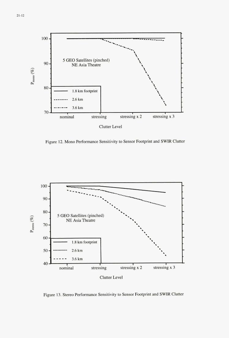
21-12
. --------____
a-. --. loo - .- *.. .- . -.-. '. '.
8. '. 5 GEO Satellites (pinched) 90 - NE Asia Theatre 8 z E 8.
d
h
0
.8 s \
.'. 8. '. - 1.8kmfmtprint
80 - ' ___---- 2.6km \.
8.
3.6 km . -._._._ 70
. -
-
-
Clutter Level
Figure 12. Mono Performance Sensitivity to Sensor Footprint and SWIR Clutter
loo - 90 -
80 - E !s
8 70- - 60
50-
40
- -----..c-_-- ---._ I-_.
------- --. ----.- ---_
*- ------.-- ---_ ---.
- '. ---.___ '- -. - . 5 GEO Satellites (pinched) *.
NE Asia Theatre . . - . . . . . . - 8 - 1.8 km footprint . .
2.6 km
3.6 km
___I- ---- . - . . - - _ _ _ I I I I
Figure 13. Stereo Performance Sensitivity to Sensor Footprint and S W Clutter
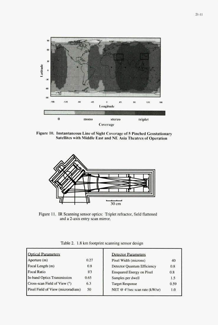
" . ., . ., . ..
A p e m ~ (m) 0.27
Focal Length (m) 0.8 Focal Ratio f13 In-band Optics Transmission 0.65 Cross-scan Field of View (") 6.3 Pixel Field of View (microradians) 50
Figure IO. lnstantanruus Line uf Sight Coterage ul'5 Pinrhrd Gcustationary Satrllites with .Middle East and NE Asia Theatres of Operation
- Pixel Width (microns) 40 Detector Quantum Efficiency 0.8 Ensquared Energy on Pixel 0.8 Samples per dwell 1.5 Target Response 0.59 NET @ 4"Isec scan rate (kWlsr) 1 .o
Figure 11. IR Scanning sensor optics: Triplet refractor, field flattened and a 2-axis entry scan mirror.
Table 2. 1.8 km footprint scanning sensor design
21-11
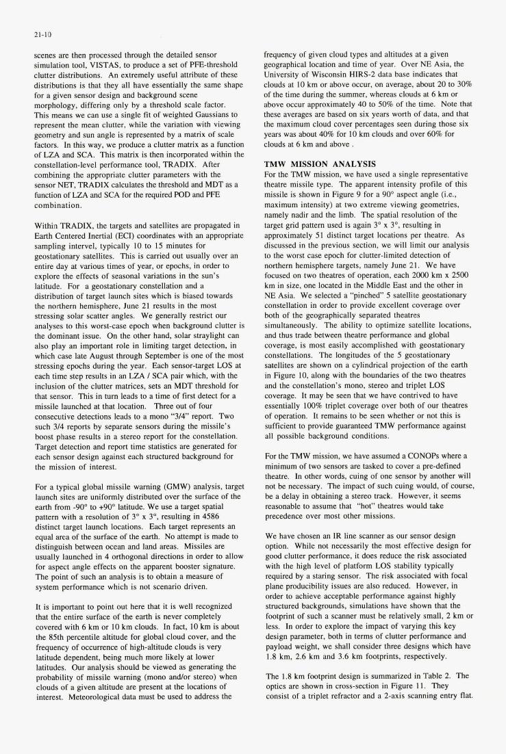
21-10
scenes are then processed through the detailed sensor simulation tool, VISTAS, to produce a set of PFEthreshold clutter distributions. An extremely useful attribute of these distributions is that they all have essentially the same shape for a given sensor design and background scene morphology, differing only hy a threshold scale factor. This means we can use a single fit of weighted Gaussians to represent the mean clutter, while the variation with viewing geometry and sun angle is represented hy a matrix of scale factors. In this way, we produce a cluner matrix as a function of LZA and SCA. This matrix is then incorporated within the constellation-level performance tool, TRADIX. After combining the appropriate clutter parameters with the sensor NET, TRADIX calculates the threshold and MDT as a function of LZA and SCA for the required POD and PIT combination.
Witbin TRADIX, the targets and satellites are propagated in Eanh Centered Inertial (WI) coordinates with an appropriate sampling intervel, typically IO to 15 minutes for geostationary satellites. This is carried out usually over an entire day at various times of year. or epochs, in order to explore the effects of seasonal variations in the sun's latitude. For a geostationary constellation and a distribution of target launch sites which is biased towards the northern hemisphere, June 21 results in the most stressing solar scatter angles. We generally restrict our analyses to this worst-case epoch when background clutter is the dominant issue. On the other hand, solar straylight can also play an important role in limiting target detection, in which case late August through September is one of the most stressing epochs during the year. Each sensor-target LOS at each time step results in an LZA I SCA pair which, with the inclusion of the clutter matrices, sets an MDT threshold for that sensor. This in turn leads to a time of first detect for a missile launched at that loeation. Three out of four consecutive detections leads to a mono "314" report. Two such 314 reports hy separate sensors during the missile's boost phase results in a stereo report for the constellation. Target detection and report time statistics are generated for each sensor design against each structured background for the mission of interest.
For a typical global missile warning (GMWI analysis, target launch sites are uniformly distributed over the surface of the earth from -90" to +No latitude. We use a target spatial pattern with a resolution of 3O x 3O. resulting in 4586 distinct target launch locations. Each target represents an equal area of the surface of the earth. No attempt is made to distinguish between ocean and land areas. Missiles are usually launched in 4 orthogonal directions in order to allow for aspect angle effects on the apparent booster signature. The point of such an analysis is to obtain a measure of system performance which is not scenario driven.
It is important to point out here that it is well recognized that the entire surface of the earth is never completely covered with 6 km or IO km clouds. In fact, IO km is ahout the 85th percentile altitude for global cloud cover, and the frequency of occurrence of high-altiNde clouds is very latitude dependent, being much more likely at lower latitudes. Our analysis should be viewed as generating the probability of missile warning (mono andlor s t ew) when clouds of a given altitude are present at the locations of interest. Meteorological data must be used to address the
frequency of given cloud types and altitudes at a given geographical location and time of year. Over NE Asia, the University of Wisconsin HIRS-2 data base indicates that clouds at IO km or above occur, on average, about 20 to 30% of the time during the summer. whereas clouds at 6 km or above occur approximately 40 to 50% of the time. Note that these averages are based on six years worth of data, and that the maximum cloud cover percentages seen during those six years was about 40% for 10 km clouds and over 60% for clouds at 6 km and above.
TMW MISSION ANALYSIS For the TMW mission, we have used a single representative theatre missile type. The apparent intensity profile of this missile is shown in Figure 9 for a 90' aspect angle (i.e.. maximum intensity) at two extreme viewing geometries, namely nadir and the limb. The spatial resolution of the target grid pattern used is again 3" x 3". resulting in approximately 51 distinct target locations per theatre. As discussed in the previous section, we will limit our analysis to the worst case, epoch for clutter-limited detection of northern hemisphere targets, namely June 21. We have focused on two theatres of operation, each 2OOO km x 2500 km in size, one located in the Middle Fast and the other in NE Asia. We selected a "pinched" 5 satellite gwstationary constellation in order to provide excellent coverage over both of the geographically separated theatres simultaneously. The ability to optimize satellite locations, and thus trade between theatre performance and global coverage, is most easily accomplished with geostationary constellations. The longitudes of the 5 geostationary satellites are shown on a cylindrical projection of the earth in Figure IO, along with the boundaries of the two theatres and the constellation's mono, stereo and triplet LOS coverage. It may be seen that we have contnved to have essentially 100% triplet coverage over both of our theatres of operation. It remains to be seen whether or not this is sufficient to provide guaranteed ThW performance against all possible background conditions.
For the TMW mission, we have assumed a CONOPs where a minimum of two sensors are tasked to cover a predefined theatre. In other words, cuing of one sensor hy another will not he necessary. The impact of such cuing would, of course, he a delay in obtaining a stereo track. However, it seems reasonable to assume that "hot? theatres would take precedence over most other missions.
We have chosen an IR line scanner as our sensor design option. While not necessarily the most effective design for good clutter performance, it does reduce the risk associated with the high level of platform LOS stability typically required hy a staring sensor. The risk associated with focal plane producihility issues are also reduced. However, in order to achieve acceptahle performance against highly structured backgrounds, simulations have shown that the footprint of such a scanner must be relatively small, 2 km or less. In order to explore the impact of varying this key design parameter, both in terms of clutter performance and payload weight, we shall consider three designs which have 1.8 km, 2.6 km and 3.6 km footprints, respectively.
The 1.8 km footprint design is summarized in Table 2. The optics are shown in cross-section in Figure 11. They consist of a triplet refractor and a 2-axis scanning entry flat
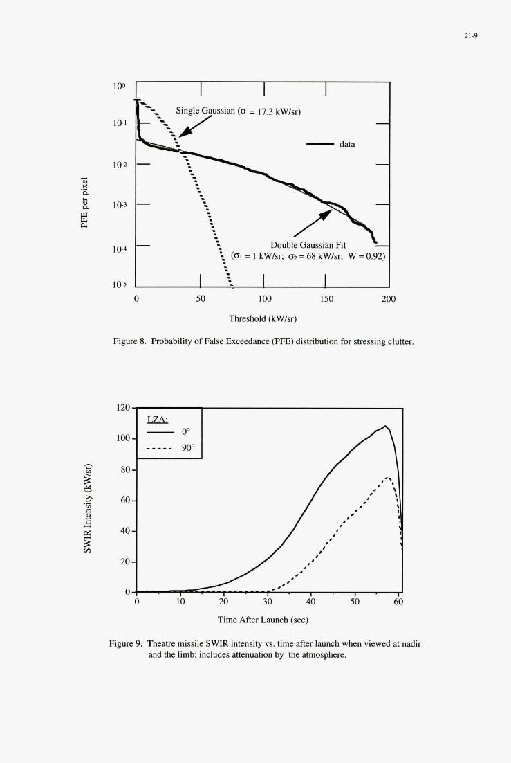
21-9
1 0 2
I 0 4
1 0 5
- data
Double Gaussian Fit
0 50 100 150 2M)
Threshold (kW/sr)
Figure 8. Probability of False Exceedance (PE) distribution for stressing clutter.
Time After Launch (sec)
Figure. 9. Theatre missile SWIR intensity vs. time after launch when viewed at nadir and the limb; includes attenuation by the atmosphere.
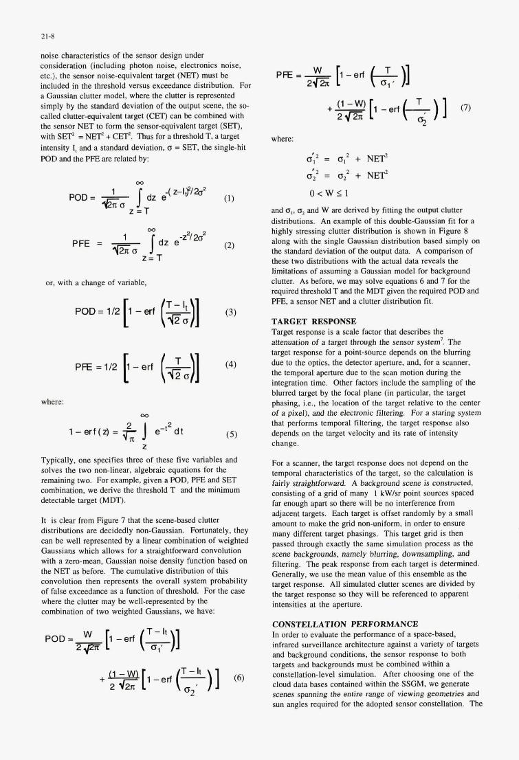
21-8
noise characteristics of the sensor design under consideration (including photon noise, electronics noise, etc.), the sensor noise-equivalent target (NET) must be included in the threshold versus exceedance distribution. For a Gaussian clutter model, where the clutter is represented simply by the standard deviation of the output scene, the so- called clutter-eqoivalent target (CET) can be combined with the sensor NET to form the sensor-cquivalent target (Sa), with S d = NEP + C&. Thus for a threshold T. a target intensity 1, and a standard deviation, a = SET, the single-hit POD and the PFE are related by:
or. with a change of variable,
POD = 112 [1- ed r&)] PA=112 I-erf - [ (41
where: 00
2 2 l - e r f ( * = T e-t dt
?I z
(3)
(4)
( 5 )
Typically, one specifies three of these five variables and solves the two non-linear, algebraic equations for the remaining two. For example, given a POD, PFE and SET combination, we derive the threshold T and the minimum detectable target (MDT).
It is clear from Figure 7 that the scenebased clutter distributions are decidedly non-Gaussian. Fortunately, they can be well represented by a linear combination of weighted Gaussians which allows for a straightfomard convolution with a zero-mean, Gaussian noise density function based on the NET as before. The cumulative distribution of this convolution then represents the overall system probability of false exceedance as a function of threshold. For the case where the clutter may he well-represented by the combination of two weighted Gaussians, we have:
where:
a': = a: + NEY 4; = a; + NEY o < w s 1
and a!, az and W are derived by fitting the output clutter distributions. An example of this doubleGaussian fit for a highly stressing clutter distribution is shown in Figure 8 along with the single Gaussian distribution based simply on the standard deviation of the output data A comparison of these two distributions with the actual data reveals the limitations of assuming a Gaussian model for background clutter. As before, we may solve equations 6 and 7 for the required threshold T and the MDT given the required POD and PFE, a sensor NET and a clutter distribution fit.
TARGET RESPONSE Target response is a scale factor that describes the menuation of a target through rbe sensor system'. The target response for a point-source depends on the blumng due to the optics, the detector apcrture, and, for a scanner. the temporal aperlure due to the scan motion during the integration time. Other factors include the sampling of the blurred target by the focal plane (in particular, the target phasing, i.e., the location of the target relative to the center of a pixel). and the electronic filtering. For a staring system that performs temporal filtering, the target response also depends on the target velocity and its rate of intensity change.
For a scanner, the target response does not depend on the temporal characteristics of the target, so the calculation is fairly straightforward. A background scene is constructed. consisting of a grid of many 1 kW/sr point sources spaced far enough apart so there will be no interference from adjacent targets. Each target is offset randomly by a small amount to make the p-id non-uniform, in order to ensure many different target phasings. This target grid is then passed through exactly the same simulation process as the scene backgrounds, namely blurring. downsampling, and filtering. The peak response from each target is determined. Generally, we use the mean value of this ensemble as the target response. All simulated clutter scenes are divided by the target response so they will be referenced to apparent intensities at the aperture.
CONSTELLATION PERFORMANCE In order to evaluate the performance of a space-based, infrared surveillance architecture against a variety of targets and background conditions, the sensor response to both targets and backgrounds must be combined within a constellation-level simulation. After chwsing one of the cloud data bases contained within the SSGM, we generate scenes spanning the entire range of viewing gwmetries and sun angles required for the adopted sensor constellation. The
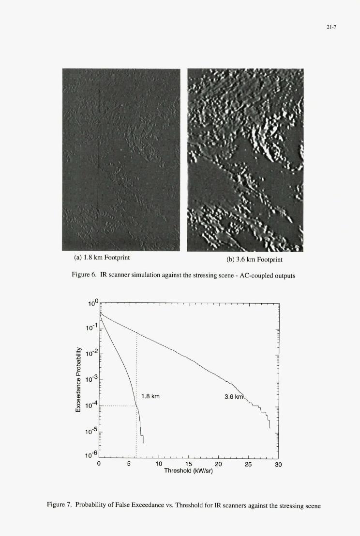
0 5 10 15 20 25 30 Threshold (kW/sr)
21-7
(a) 1.8 km Footprint
Figure 6. IR scanner simulation against the stressing scene - AC-coupled outputs
(b) 3.6 km Footprint
Figure 7. Probability of False Exceedance vs. Threshold for IR scanners against the stressing scene
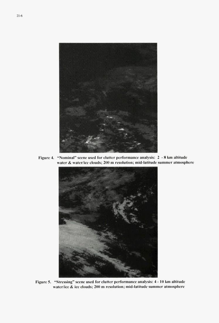
-* *
I Figure 4. Y.olrlmaI" scene u s d fur rluttcr pcrfurmancc analysis: 2 - X km altitude
wattr & watcr/ice clouds; 200 m resolution; mid-latitudr summer atmosphere
Figure 5. "Stressing" scene used for clutter perliurmanee analysis: 4 - I O km altitude water/iee & ice clouds; 200 m resolution; mid-latitude summrr atmosphere
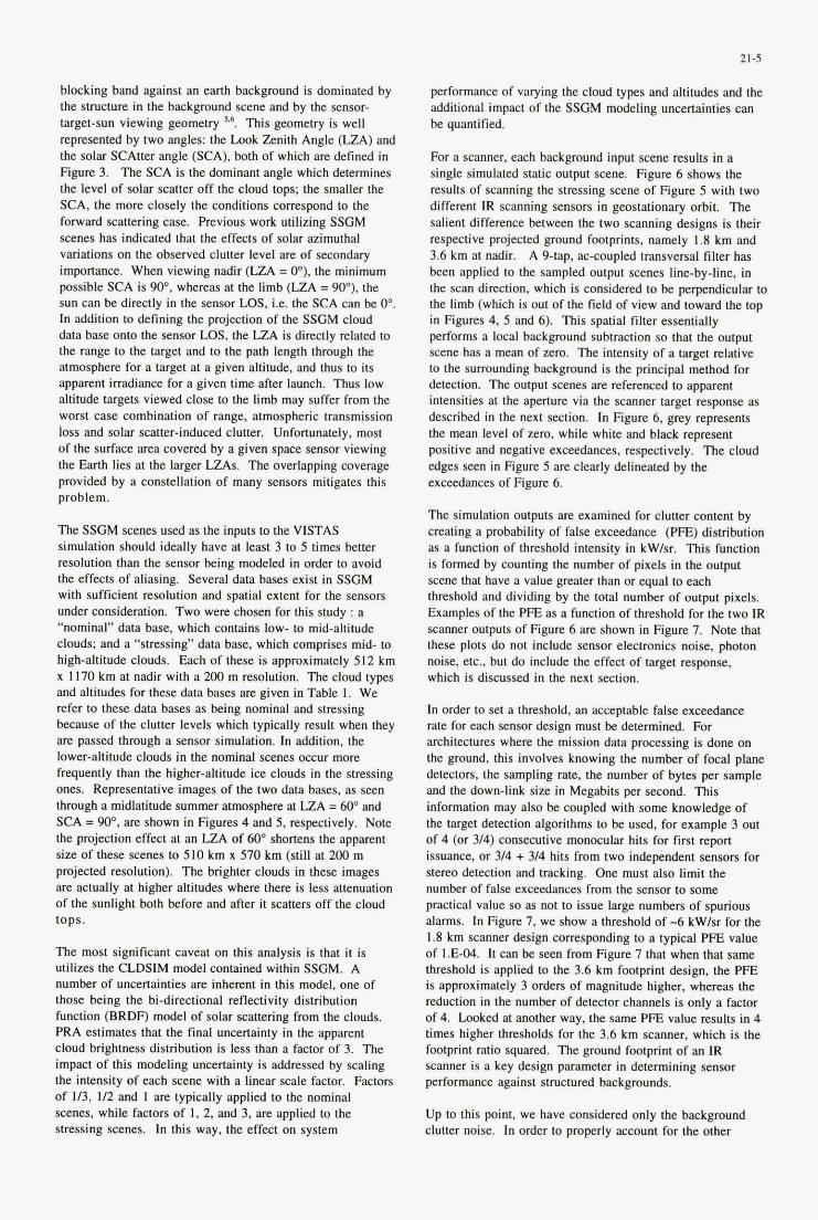
21-5
performance of varying the cloud types and altitudes and the additional impact of the SSGM modeling uncertainties can be quantified.
For a scanner, each background input scene results in a single simulated static output scene. Figure 6 shows the results of scanning the stressing scene of Figure 5 with two different IR scanning sensors in geostationary orbit. The salient difference between the two scanning designs is their respective projected ground footprints. namely 1.8 km and 3.6 km at nadir. A g-tap, ac-coupled transversal filter has been applied to the sampled output scenes line-by-line, in the scan direction, which is considered to be perpendicular to the limb (which is out of the field of view and toward the top in Figures 4, 5 and 6). This spatial filter essentially performs a local background subtraction so that the output scene has a mean of zero. The intensity of a target relative to the surrounding background is the principal method for detection. The output scenes are referenced to apparent intensities at the aperture via the scanner target response as described in the next section. In Figure 6, grey represents the mean level of zero, while white and black represent positive and negative exceedances, respectively. The cloud edges seen in Figure 5 are clearly delineated by the exceedances of Figure 6.
blocking band against an earth background is dominated by the structure in the background scene and by the sensor- target-sun viewing geometry ',6. This geometry is well represented by two angles: the Look Zenith Angle (LZA) and the solar SCAtter angle (SCA), both of which are defined in Figure 3. The SCA is the dominant angle which determines the level of solar scatter off the cloud tops; the smaller the SCA, the more closely the conditions correspond to the forward scattering case. Previous work utilizing SSGM scenes has indicated that the effects of solar azimuthal variations on the observed clutter level are of secondary importance. When viewing nadir (LZA = O"), the minimum possible SCA is 90". whereas at the limb (LZA = go"), the sun can be directly in the sensor LOS, i.e. the SCA can be 0". I n addition to defining the projection of the SSGM cloud data base onto the sensor LOS. the LZA is directly related to the range to the target and to the path length through the atmosphere for a target at a given altitude, and thus to its apparent irradiance for a given time after launch. Thus low altitude targets viewed close to the limb may suffer from the worst case combination of range, atmospheric transmission loss and solar scatter-induced clutter. Unfortunately, most of the surface area covered by a given space sensor viewing the Earth lies at the larger LZAs. The overlapping coverage provided by a constellation of many sensors mitigates this problem.
The SSGM scenes used as the inputs to the VISTAS simulation should ideally have at least 3 to 5 times better resolution than the sensor being modeled in order to avoid the effects of aliasing. Several data bases exist in SSGM with sufficient resolution and spatial extent for the sensors under consideration. Two were chosen for this study : a "nominal" data base, which contains low- to mid-altitude clouds; and a "stressing" data base, which comprises mid- to high-altitude clouds. Each of these is approximately 512 km x I170 km at nadir with a 200 m resolution. The cloud types and altitudes for these data bases are gjven in Table I . We refer to these data bases as being nominal and stressing because of the clutter levels which typically result when they are passed through a sensor simulation. In addition, the lower-altitude clouds in the nominal scenes occur more frequently than the higher-altitude ice clouds in the stressing ones. Representative images of the two data bases, as seen through a midlatitude summer atmosphere at LZA = 60" and SCA = 90". are shown in Figures 4 and 5, respectively. Note the projection effect at an LZA of 60" shortens the apparent size of these scenes to 510 km x 570 km (still at 200 m projected resolution). The brighter clouds in these images are actually at higher altitudes where there is less attenuation of the sunlight both before and after it scatters off the cloud tops.
The most significant caveat on this analysis is that it is utilizes the CLDSIM model contained within SSGM. A number of uncertainties are inherent in this model, one of those being the bi-directional reflectivity distribution function (BRDF) model of solar scattering from the clouds. PRA estimates that the final uncertainty in the apparent cloud brightness distribution is less than a factor of 3. The impact of this modeling uncertainty is addressed by scaling the intensity of each scene with a linear scale factor. Factors of 113, I / Z and I are typically applied to the nominal scenes, while factors of 1. 2, and 3, are applied to the stressing scenes. In this way, the effect on system
The simulation outputs are examined for clutter content by creating a probability of false exceedance ( P E ) distribution as a function of threshold intensity in kW1sr. This function is formed by counting the number of pixels in the output scene that have a value greater than or equal to each threshold and dividing by the total number of output pixels. Examples of the PFE as a function of threshold for the two IR scanner outputs of Figure 6 are shown in Figure 7. Note that these plots do not include sensor electronics noise, photon noise, etc., but do include the effect of target response. which is discussed in the next section.
In order to set a threshold, an acceptable false exceedance rate for each sensor design must be determined. For architectures where the mission data processing is done on the ground, this involves knowing the number of focal plane detectors. the sampling rate, the number of bytes per sample and the down-link size in Megabits per second. This information may also be coupled with some knowledge of the target detection algorithms to be used, for example 3 out of 4 (or 314) consecutive monocular hits for first report issuance, or 314 + 314 hits from two independent sensors for stereo detection and tracking. One must also limit the number of false exceedances from the sensor to some practical value so as not to issue large numbers of spurious alarms. In Figure 7, we show a threshold of -6 kW1sr for the 1.8 km scanner design corresponding to a typical PFE value of 1.E-04. It can be seen from Figure 7 that when that same threshold is applied to the 3.6 km footprint design, the PFE is approximately 3 orders of magnitude higher, whereas the reduction in the number of detector channels is only a factor of 4. Looked at another way, the same PFE value results in 4 times higher thresholds for the 3.6 km scanner, which is the footprint ratio squared. The ground footprint of an IR scanner is a key design parameter in determining sensor performance against structured backgrounds.
Up to this point, we have considered only the background clutter noise. I n order to properly account for the other
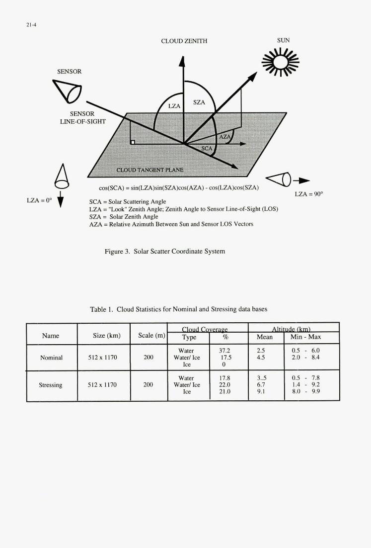
21-4
CLOUD ZE" SUN
SENSOR
D SEN:
LINE-OF
A t LZA = 00
SENSOR
D SENS
LINE-OF-SIGHT
cos(SCA) = sin(LZA)sin(SZA)cos(AZA) - cos(LZA)cos(SZA) LZA =
cos(SCA) = sin(LZA)sin(SZA)cos(AZA) - cos(LZA)cos(SZA) LZA =
SCA = Solar Scattering Angle LZA = "Look' Zenith Angle; Zenith Angle to Sensor Line-of-Sight (LOS) SZA = Solar Zenith Angle AZA =Relative Azimuth Between Sun and Sensor LOS Vectors
Figure 3. Solar Scatter Coordinate System
Table 1. Cloud Statistics for Nominal and Stressing data bases
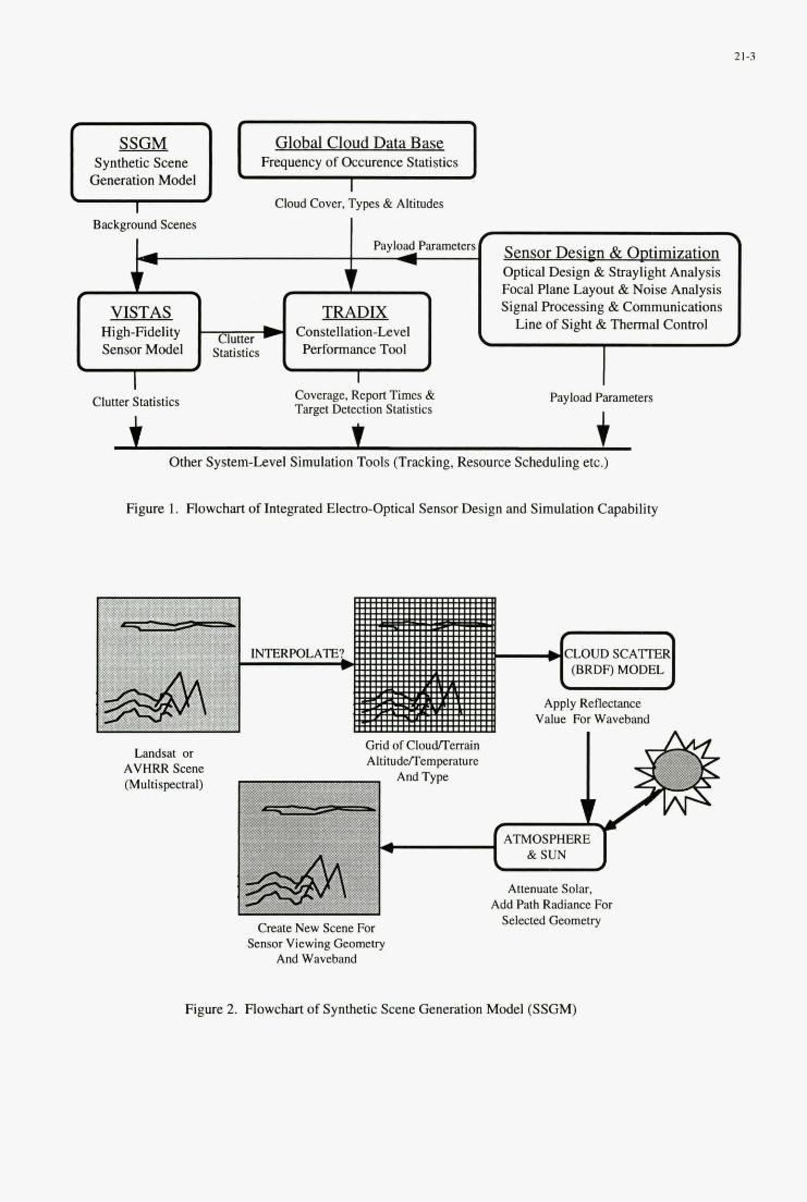
21-3
Global Cloud Data Bas Frequency of Occurence Statistics
Cloud Cover, Types & Altitudes
Synthetic Scene Generation Model
Background Scenes
Sensor Desien & Ootimizatio n Optical Design & Straylight Analysis Focal Plane Layout &Noise Analysis Signal Processing & Communications
Line of Sight & Thermal Control
Payload Parametersf 1
r + f 3 VISTAS TRADM
Constellation-Level High-Fidelity Sensor Model statistics Performance Tool
\ # # \
Clutter \
I I Clutter Statistics Coverage, Report Times &
Target Detection Statistics Payload Parameters
I IC Other System-Level Simulation Tools (Tracldng. Resource Scheduling etc.)
Figure 1. Flowchart of Integrated Electro-Optical Sensor Design and Simulation Capability
Landsat or AVHRR Scene (Multispeetrd)
Grid of CloudJTerrain AltitudelTemocrature
Create New Scene For Sensor Viewing Geometry
And Waveband
ATMOSPHERE
Attenuate Solar, Add Path Radiance For
Selected Geometry
Figure 2. Flowchart of Synthetic Scene Generation Model (SSGM)
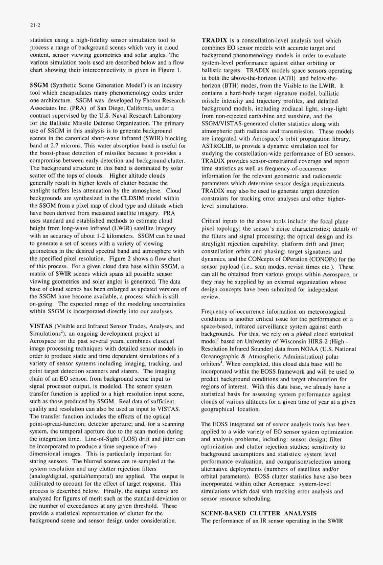
21-2
statistics using a high-fidelity sensor simulation tool to process a range of background scenes which vary in cloud content, sensor viewing geometries and solar angles. The various simulation tools used are described below and a flow chart showing their interconnectivity is given in Figure 1.
SSGM (Synthetic Scene Generation Model') is an industry tool which encapsulates many phenomenology codes under one architecture. SSGM was developed by Photon Research Associates Inc. (PRA) of San Diego, California, under a contract supervised by the U.S. Naval Research Laboratory for the Ballistic Missile Defense Organization. The primary use of SSGM in this analysis is to generate background scenes in the canonical short-wave infrared (SWIR) blocking band at 2.7 microns. This water absorption band is useful for the boost-phase detection of missiles because it provides a compromise hetween early detection and background clutter. The background structure in this band is dominated by solar scatter off the tops of clouds. Higher altitude clouds generally result in higher levels of clutter because the sunlight suffers less attenuation by the atmosphere. Cloud backgrounds are synthesized in the CLDSIM model within the SSGM from a pixel map of cloud type and altitude which have been derived from measured satellite imagery. PRA uses standard and established methods to estimate cloud height from long-wave infrared (LWIR) satellite imagery with an accuracy of about 1-2 kilometers. SSGM can be used to generate a set of scenes with a variety of viewing geometries in the desired spectral hand and atmosphere with the specified pixel resolution. Figure 2 shows a flow chart of this process. For a given cloud data base within SSGM, a matrix of SWIR scenes which spans all possible sensor viewing geometries and solar angles is generated. The data base of cloud scenes has been enlarged as updated versions of the SSGM have become available. a process which is still on-going. The expected range of the modeling uncertainties within SSGM is incorporated directly into our analyses.
VISTAS (Visible and Infrared Sensor Trades, Analyses, and Simulations'), an ongoing development project at Aerospace for the past several years, combines classical image processing techniques with detailed sensor models in order to produce static and time dependent simulations of a variety of sensor systems including imaging, tracking, and point target detection scanners and starers. The imaging chain of an EO sensor. from background scene input to signal processor output, is modeled. The sensor system transfer function is applied to a high resolution input scene, such as those produced by SSGM. Real data of sufficient quality and resolution can also be used as input to VISTAS. The transfer function includes the effects of the optical point-spread-function; detector aperture; and, for a scanning system, the temporal aperture due to the scan motion during the integration time. Line-of-Sight (LOS) drift and jitter can be incorporated to produce a time sequence of two dimensional images. This is particularly important for staring sensors. The blurred scenes are re-sampled at the system resolution and any clutter rejection filters (analogldigital, spatiaUtemporal) are applied. The output is calibrated to account for the effect of target response. This process is described below. Finally, the output scenes are analyzed for figures of merit such as the standard deviation or the number of exceedances at any given threshold. These provide a statistical representation of clutter for the background scene and sensor design under consideration.
TRADIX is a constellation-level analysis tool which combines EO sensor models with accurate target and background phenomenology models in order to evaluate system-level performance against either orbiting or ballistic targets. TRADU models space sensors operating in both the above-the-horizon (ATH) and below-the- horizon (BTH) modes, from the Visible to the LWIR. It contains a hard-body target signature model, ballistic missile intensity and trajectory profiles. and detailed background models, including zodiacal light, stray-light from non-rejected earthshine and sunshine, and the SSGWVISTAS-generated clutter statistics along with atmospheric path radiance and transmission. These models are integrated with Aerospace's orbit propagation library, ASTROLIB, to provide a dynamic simulation tool for studying the constellation-wide performance of EO sensors. TRADIX provides sensor-constrained coverage and report time statistics as well as frequency-of-occurrence information for the relevant geometric and radiometric parameters which determine sensor design requirements. TRADIX may also be used to generate target detection constraints for tracking error analyses and other higher- level simulations.
Critical inputs to the above tools include: the focal plane pixel topology; the sensor's noise characteristics; details of the filters and signal processing; the optical design and its straylight rejection capability; platform drift and jitter; constellation orhits and phasing; target signatures and dynamics, and the CONcepts of Operation (CONOPs) for the sensor payload (i.e.. scan modes, revisit times etc.). These can all be obtained from various groups within Aerospace, or they may be supplied by an external organization whose design concepts have been submitted for independent review.
Frequency-of-occurrence information on meteorological conditions is another critical issue for the performance of a space-based, infrared surveillance system against earth backgrounds. For this, we rely on a global cloud statistical model' based on University of Wisconsin HIRS-2 (High - Resolution Infrared Sounder) data from NOAA (U.S. National Oceanographic & Atmospheric Administration) polar orbiters'. When completed, this cloud data base will be incorporated within the EOSS framework and will be used to predict background conditions and target obscuration for regions of interest. With this data base. we already have a statistical basis for assessing system performance against clouds of various altitudes for a given time of year at a given geographical location.
The EOSS integrated set of sensor analysis tools has been applied to a wide variety of EO sensor system optimization and analysis problems, including: sensor design; filter optimization and clutter rejection studies; sensitivity to background assumptions and statistics; system level performance evaluation. and comparisodseleetion among alternative deployments (numbers of satellites and/or orbital parameters). EOSS clutter statistics have also been incorporated within other Aerospace system-level simulations which deal with tracking error analysis and sensor resource scheduling.
SCENE-BASED CLUTTER ANALYSIS The performance of an IR sensor operating in the SWIR
Rdm-Optid Semor Sirmlation for lbeahe Missile Waming
D.G. M e S.L Wesjian J.N. Hanilton
EJ. h e y IS. Robillson MM. Jacohr:
THE AEROSPACE CORPORATION Post Office Box 92957. M4I041 Los Angeles CA 90009-2957
USA.
SUMMARY An integrated Electro-Optical Sensor Simulation (EOSS) capability has been developed which can analyze the performance of space-based. surveillance systems at both the sensor and constellation levels. For sensors operating in an inihred-blocking band against an earth background, target detection is generally limited by sensor output variations known as clutter, which results from the interaction of the sensor with background scene strucNre such as clouds. EOSS uses a scene generation model to create the required cloud scenes and an end-to-end simulation of the imaging chain to evaluate the impact of these backgrounds on sensor performance. Results from these detailed simulations are combined within a constellation-level analysis tool to provide global sensor coverage and target detection statistics as a function of sensor design, background level, target parameters, and constellation size and type. This simulation capability has been used to determine theatre missile detection and report times for a representative space- based, infrared surveillance architecNre. The trade between sensor performance and payload weight has also been explored, with uncertainties in the background clutter modeling playing a key role in driving the sensor designs in the direction of heavier and more expensive payloads.
INTRODUCTION The ability to provide early warning against theatre missile attack has become a key mission area for NATO military planners. A space-based, infrared surveillance system can indeed provide such warning. However, enhancing the timeliness and utility of any future space-based, infrared surveillance system will depend greatly on an accurate appraisal of the phenomenology involved and its impact on sensor design and performance. System performance may be seriously compromised if non-optimum sensor designs or system architecNres are deployed.
The Aerospace Corporation (Aerospace), which supplies general systems engineering and integration services to the US. Air Force’s Space and Missile Systems Center, is often asked to provide quick-response assessments of a wide variety of space-based sensor concepts. Frequently, an analytical approach is deemed sufficient to meet the accuracy required for such assessments. Sometimes, however, highly detailed simulations an required, especially when the assumptions underlying the analytical approximations have been violated. For example, a key component in many sensor performance evaluations is the spatial structure of the background against which target detection must be accomplished. For analytical approximations. it is
typically assumed that the background amplitude distribution is Gaussian, leading to a simple convolution of the background clutter with the noise distribution inherent to the sensor. However. many backgrounds do not have Gaussian ampliNde distributions because of commonly occurring features such as cloud edges, landsea interfaces, etc. Under such circumstances, detailed pixel-level focal plane simulations are required if an accurate assessment of the sensor*s performance is to be made. On the other hand, when the emphasis is on the system performance of a constellation of sensors, such a level of detail has generally been viewed as too time consuming and costly to incorporate within a constellation-level simulation.
This paper describes a methodology for accurately quantifying the impact of spatially-structured backgrounds on the performance of space-based infrared sensors and, further, to couple these results with higher-order systems engineering trades and mission performance tools. In effect, high-fidelity sensor and phenomenology models are used to generate constraints and data bases for use within constellation-level simulations, thereby enhancing their overall accuracy. This integrated simulation capability has been used to support both sensor and systems trades for a number of space-based, infrared surveillance system studies, including those dealing with Theatre Missile Warning 0. In order to illustrate the models and analysis p d u r e s . we evaluate a nominal space -bd , infrared surveillance architecture against the TMW mission for two potential theatres of operation. System performance is derived for three generic IR scanning sensor designs, and parameterized against the potential variations and uncertainties in the background structure. We also examine the cost. as characterized by payload weight, of meeting the high levels of performance likely to be required by future theatre commanders.
SIMULATION TOOLS For a space-based, infrared surveillance system, the simultaneous interplay between the sensor, target and background determines the capability for target detection. Thus, in order to accurately predict the ability of an EO sensor constellation to perform a given mission, it is necessary to incorporate all of the salient geometry, dynamics and phenomenology into a single tool. One of the main focuses of our effort to develop an integrated w) sensor simulation has been to incorporate the effects of realistic clutter phenomena (i.e. cloud edges, sun glints. etc.) within constellation-level, space surveillance simulations. Our mechanism for accomplishing this is to generate clutter
Paper presented at the AGARD MSP 5‘* Symposium on “Space Systems as Contributors to the NATO Defence Mission”, held in Cannes, France, 3-6 June 1996, andpublished in CP-580
24-1
INTEGRATED AIR DEPLOYED STRIKE SURVEILLANCE (IADSS)
Capt. Patrick O’Connell, Ph.D., USN Dr. Daria J. Bielecki
Office of Naval Research Space Technology & Liaison Office 800 N. Quincy Balston Tower #1
Arlington, VA. 22217-5650
I. SUMMARY
The U.S. Navy‘s Integrated Air Deployed Strike Surveillance (IADSS) initiative is a pathfinder effort in defining the next genera- tion sensor and mission manage- ment systems for unmanned air vehicles (UAV). The sensor suite in development will be capable of deterministic to fully autonomous operations. This includes the capabilities for dissimilar sensor queuing, automatic sensor search and automatic target recognition. A key developmental item is the autonomous management system (AMS) that will “manage” the ex- panded onboard sensor suite. The envisioned equipment suite includes signal detection equip- ment, imagery systems and a duplex communication system.
This paper is presented in three parts: an overview, the operational demonstrations and the supporting Science and Technology.
I[. OVERVIEW
1. INTRODUCTION
The IADSS capability can sup- port the NATO Defense Space Systems Mission. An organic surveillance asset with space con- nectivity that is capable of passive and active wide area surveillance supports tactical, strategic, intelli- gence and precision strike targeting missions. This initiative also advances the state-of-the-art in autonomous airborne sensor management in the areas of fusion, integration, processing and com- munications. The planned onboard sensor systems include Signal Intel- ligence (SIGINT) systems, Electro- Optical/ Infrared Sensors (EO/IR), and Synthetic Aperture Radar (SAR).
2. ORGANIZATION
The IADSS project organiza- tion, shown in Figure 1 is com- prised of three Integrated Product Teams (IPTs): (a) S&T Develop- ment; (b) Demonstrations; and (c) Autonomous Management System (AMs). The IADSS management and technical staff are from the Office of Naval Research (ONR), the Naval Research Laboratory
Paper presenfed at fhe AGARD MSP 5rk Symposium on “Space Sysfems as Conrribufors to the NATO Defence Mission”, held in Cannes, France, 3-6 June 1996, and published in CP-580.
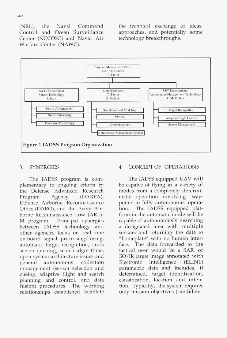
24-2
(NRL), the Naval Command the technical exchange of ideas, Control and Ocean Surveillance approaches, and potentially some Center (NCCOSC) and Naval Air Warfare Center (NAWC).
technology breakthroughs.
Program Management Office C A W OConnell
T. Taylor
S&T Develapmenl Demonstrations S&T Development Sensor Technology Autonomous Management Technology
I I I Simulation and Modeling Target Recognition Sensor Advancement
Signnl Processing
Proccwx Technology Adaptive Righi Control
Communicauonr Senror Minagemmi
n I H Simulation and Modeling I H Target Recognition Sensor Advancement
1 Procc\\or Technology
IFigure 1 IADSS Program Organization
3. SYNERGIES
The IADSS program is com- plementary to ongoing efforts by the Defense Advanced Research Program Agency (DARPA), Defense Airborne Reconnaissance Office (DARO), and the Army Air- borne Reconnaissance Low (ARL)- M program. Principal synergies between IADSS technology and other agencies focus on real-time on-board signal processing/fusing, automatic target recognition, cross sensor queuing, search algorithms, open system architecture issues and general autonomous collection management (sensor selection and cueing, adaptive flight and search planning and control, and data fusion) procedures. The working relationships established facilitate
4. CONCEPT OF OPERATIONS
The IADSS equipped UAV will be capable of flying in a variety of modes from a completely determi- nistic operation involving way- points to fully autonomous opera- tion. The IADSS equipped plat- form in the automatic mode will be capable of autonomously searching a designated area with multiple sensors and returning the data to "homeplate" with no human inter- face. The data forwarded to the tactical user would be a SAR or EO/IR target image annotated with Electronic Intelligence (ELINT) parametric data and includes, if determined, target identification, classification, location and inten- tion. Typically, the system requires only mission objectives (candidate
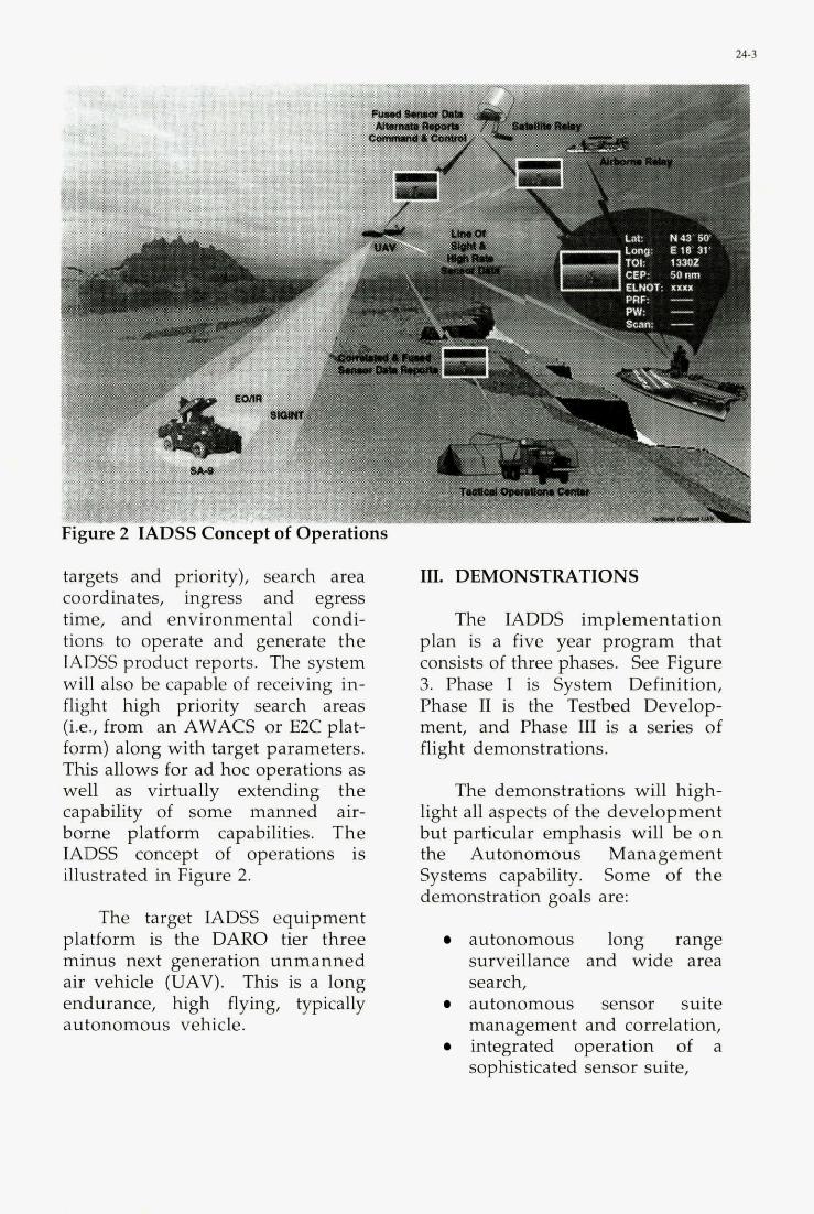
targets and priority), search area coordinates, ingress and egress time, and environmental condi- tions to operate and generate the IADSS product reports. The system will also be capable of receiving in- flight high priority search areas (i.e., from an AWACS or E2C plat- form) along with target parameters. This allows for ad hoc operations as well as virtually extending the capability of some manned air- borne platform capabilities. The MDSS concept of operations is iIlustrated in Figure 2.
The target IADSS equipment platform is the DARO tier three minus next generation unmanned air vehicle (UAV). This is a long endurance, high flying, typically autonomous vehicle.
III. DEMONSTRATIONS
The IADDS implementation plan is a five year program that consists of three phases. See Figure 3. Phase I is System Definition, Phase IJ is the Testbed Develop- ment, and Phase III is a series of flight demonstrations.
The demonstrations will high- light all aspects of the development but particular emphasis will be on the Autonomous Management Systems capability. Some of the demonstration goals are:
autonomous long range surveillance and wide area search, autonomous sensor suite management and correlation, integrated operation of a sophisticated sensor suite,
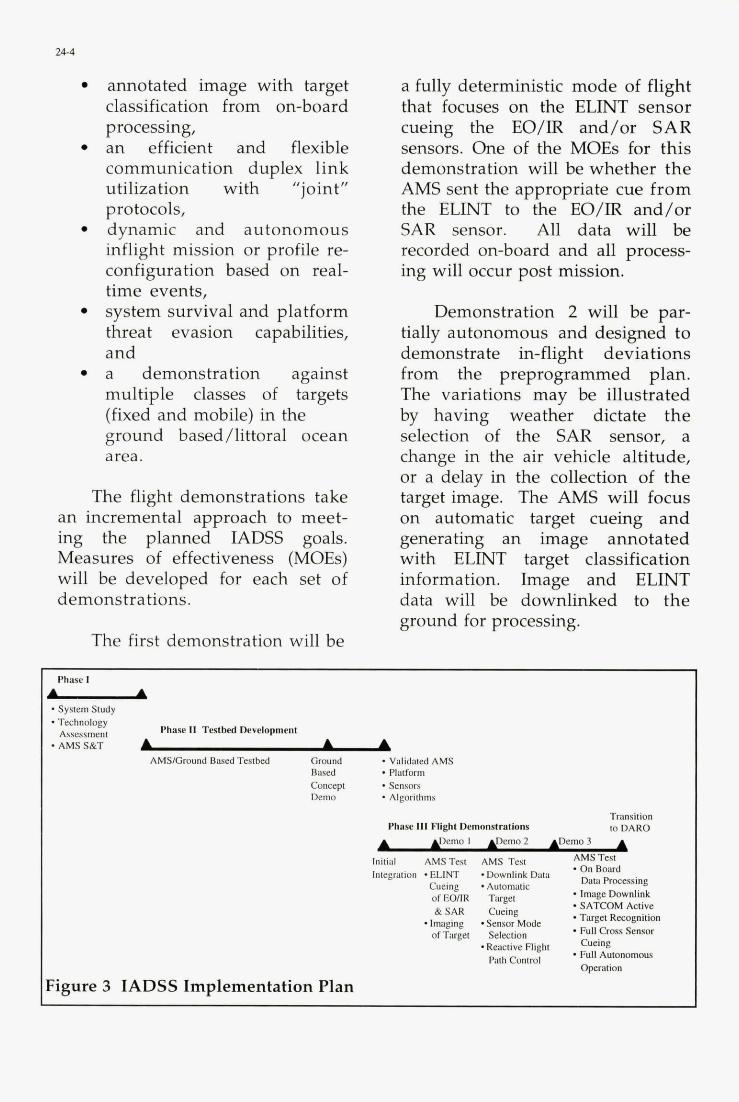
24-4
annotated image with target classification from on-board processing, an efficient and flexible communication duplex link utilization with "joint" protocols, dynamic and autonomous inflight mission or profile re- configuration based on real- time events, system survival and platform threat evasion capabilities, and a demonstration against multiple classes of targets (fixed and mobile) in the ground based /littoral ocean area.
The flight demonstrations take an incremental approach to meet- ing the planned IADSS goals. Measures of effectiveness (MOEs) will be developed for each set of demonstrations.
The first demonstration will be
a fully deterministic mode of flight that focuses on the ELINT sensor cueing the EO/IR and/or SAR sensors. One of the MOEs for this demonstration will be whether the AMS sent the appropriate cue from the ELINT to the EO/IR and/or SAR sensor. All data will be recorded on-board and all process- ing will occur post mission.
Demonstration 2 will be par- tially autonomous and designed to demonstrate in-flight deviations from the preprogrammed plan. The variations may be illustrated by having weather dictate the selection of the SAR sensor, a change in the air vehicle altitude, or a delay in the collection of the target image. The AMS will focus on automatic target cueing and generating an image annotated with ELINT target classification information. Image and ELINT data will be downlinked to the ground for processing.
Phase I U * System Study * Technology
Assessment * AMS S&T
Figure 3 IADSS Implementation Plan
Phase I1 Testbed Development
b A A AMS/Ground Bayed Testbed Ground * Validated AMS
Bared . Platform Concept . Sensors Demo Algorithms
Transition to DARO Phase 111 Fllght Demonstrations
b g e m o i em02 &IDemo3 A AMs Test - On Bourd
Initial AMSTest AMS Test
Daw Prwessing Inlegration ELlNT *Downlink Datu Cueing - Aaom&tic ofEOm( Target - SATCOM Active
* Target Recognition & S A R Cueing
of Taget Selection * Full Cmss Sensor -Reactive Flight Cueing - Fun Autonomous
.Image Downlink
-Imaging -Sensor Mode
Path Contml Operation
24-5
Demonstration 3 will be a fully autonomous test flight that examines the full range of AMS capabilities. Typical scenarios for this demonstration will require the vehicle to fly preplanned routes, general search routes and demon- strate a reactive capability. For example, a manned airborne plat- form will send tasking to IADSS to alter it’s flight path, seek a non apriori target, generate an image and send this image to the airborne platform. The image will be anno- tated and downlinked to the originating command.
IV. TECHNOLOGY
The technology areas in the IADSS initiative focus on the AMS an.d the three onboard sensors - SIGINT, EO/IR, and SAR.
The AMS is expected to produce advancements in algorithmic developments in the area of sensor search, sensor cueing, target location, recognition and identification, and some form of flight control. Functional decomposition will be used to develop a modular architecture of the AMs. Modules include route planning, sensor performance models, sensor capability models, sensor management suite, vehicle rules, optimization, conflict resolu- tion, automatic target cueing, automatic target recognition, and weather modules.
The SIGINT sensor used during the demonstrations will have a spectrum range of approxi- mately 2-18 GHz. Expected geoloca-
tion accuracy of less than 1 km will be achieved through a hybrid of the Time Difference of Arrival (TDOA) technique and interferometric approach. The sensor technology will support the capability to detect frequency hopped or chirped signals. It will have a wide field of view with sidelobe detection sensitivity. This sidelobe capability will be able to detect and locate targets that employ a variety of scan types including track while scan radars. In order to imitate operational scenarios, the SIGINT tests will be conducted in high density environments. By the year 2000, the coverage is expected to be 0.8 GHz to 18 GHz.
The EO/IR sensor used in the demonstrations will employ long and medium wave infrared (LWIR) & (MWIR) along with visible bands with multispectral cueing capability. In addition, the system requirements for the EO/R sensor include the capability of being cued by the SIGINT or SAR sensor.
The goal for the transition year is to have developed a multi- spectral IR system using a focal plane array (FPA) employing opti- cal signal processing. This multi- spectral sensor will use scanning FPAs with separate scanner modules for the visible and IR multi-spectral imagers. One scan will search the area designated by the SIGINT sensor while a larger scan will be used to search the local area. S&T issues that need to be resolved include the registration and spectral purity of the images
24-6
and the development of the multi- color FPA.
The SAR used for demonstra- tions will have 1 foot resolution and the ability to detect slow moving ground targets. The system requirements also include the capability of being cued from the SIGINT or the EO/IR sensor and to employ a ground moving target indicator (GMTI) mode. The SAR and the EO/IR sensor must be capable of recognition and detec- tion in clutter along with precision tracking after recognition. By the year 2000 the resolution should have improved to 0.5 foot resolu- tion. There are plans to have enhanced geolocation algorithms in place and to include moving target imaging.
IADSS S&T efforts will focus on advancing sensor capabilities and signal processing techniques to meet the requirements for autonomous operations and target classification and identification. During Phase I, S&T requirements will be defined, existing technology surveyed, ongoing S&T programs evaluated, and IADSS S&T tasks initiated. The relative value of S&T results will then be evaluated using modeling and simulation techniques. S&T efforts that are ready for inclusion in the opera- tional demonstration will be inte- grated into the IADSS Phase I1 Ground Based Concept Demonstration and Phase I11 Flight Demonstrations.
The key S&T candidate thrust areas include;
autonomous sensor manage- ment; high speed real-time signal processing; multi-sensor correlation; multi-spectral EO/IR sensors;
ultra high resolution sensors, multi-spectral FPAs and associated signal and image processing methods; shared aperture and electroni- cally or optically controlled shutters (for radar cross section reductions) for RF, SIGINT, and EO/IR sensors; lightweight antennas that operate over the SAR and SIGINT spectral range; and efficient, light weight prime power generation.
Of particular interest are "smart" multi-spectral FPAs where the readout circuits are integral to the FPA. The FPA must be dual- band with three bands being prefer- able. The IR device must be capable of providing "color" discrimina- tion,
SIGINT improvements will focus on reducing the typical detractors from geolocation accu- racy such as pulse correlation, timing issues, atmospheric correc- tions and self-diagnostic error budgets.
Platform or mission issues such as dynamic flight and search planning, near real-time battle damage assessment (BDA), and autonomous decision aids will be investigated.

24-1
V. CONCLUSIONS weather surveillance capabilities I for future operational systems.
The IADSS initiative will Further, the onboard duplex com- provide supporting developmental and empirical data to shape the fu- ture path of Unmanned Air Vehicles. The dissimilar sensor queuing and the Automatic Target Recognition algorithms, along with the Autonomous Management Prototype efforts are particularly useful in developing day-night, all
munications capability that is capable of receiving updated priori- ties and allows onboard images to be forwarded to satellites (for re- broadcast), airplanes, and surface units, allows this platform to be used as a tactical, strategic or intel- ligence asset.

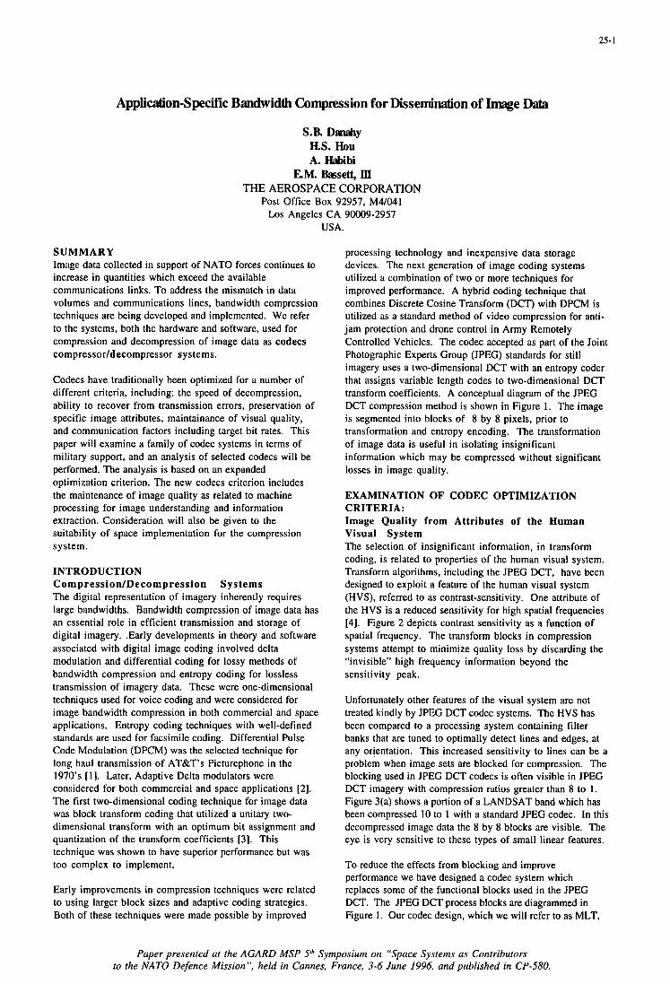
25-1
Application-Specific Bandwidth Compkssion for Dissemination of Image Jhta
S.B. Dan&y HS. €IOU A. IIabibi
EM. &sett, III THE AEROSPACE CORPORATION
Post Office Box 92957, M4/041 Los Angeles CA 90009-2957
USA.
SUMMARY Image data collected in support of NATO forces continues to increase in quantities which exceed the available communications links. To address the mismatch in data volumes and communications lines, bandwidth compression techniques are being developed and implemented. We refer to the systems, both the hardware and software, used for compression and decompression of image data as codecs compressorldecompressor systems.
Codecs have traditionally been optimized for a number of different criteria, including: the speed of decompression, ability to recover from transmission errors, preservation of specific image attributes, maintainance of visual quality, and communication factors including target bit rates. This paper will examine a family of codec systems in terms of military support, and an analysis of selected codecs will be performed. The analysis is based on an expanded optimization criterion. The new codecs criterion includes the maintenance of image quality as related to machine processing for image understanding and information extraction. Consideration will also be given to the suitability of space implementation for the compression system.
INTRODUCTION C om p r essi on/De compress ion The digital representation of imagery inherently requires large bandwidths. Bandwidth compression of image data has an essential role in efficient transmission and storage of digital imagery. .Early developments in theory and software associated with digital image coding involved delta modulation and differential coding for lossy methods of bandwidth compression and entropy coding for lossless transmission of imagery data. These were one-dimensional techniques used for voice coding and were considered for image bandwidth compression in both commercial and space applications. Entropy coding techniques with well-defined standards are used for facsimile coding. Differential Pulse Code Modulation (DPCM) was the selected technique for long haul transmission of AT&T’s Picturephone in the 1970’s [l]. Later, Adaptive Delta modulators were considered for both commercial and space applications [2]. The first two-dimensional coding technique for image data was block transform coding that utilized a unitary two- dimensional transform with an optimum bit assignment and quantization of the transform coefficients [3]. This technique was shown to have superior performance but was too complex to implement.
Sys tems
Early improvements in compression techniques were related to using larger block sizes and adaptive coding strategies. Both of these techniques were made possible by improved
processing technology and inexpensive data storage devices. The next generation of image coding systems utilized a combination of two or more techniques for improved performance. A hybrid coding technique that combines Discrete Cosine Transform (DCT) with DPCM is utilized as a standard method of video compression for anti- jam protection and drone control in Army Remotely Controlled Vehicles. The codec accepted as part of the Joint Photographic Experts Group (JPEG) standards for still imagery uses a two-dimensional DCT with an entropy coder that assigns variable length codes to two-dimensional DCT transform coefficients. A conceptual diagram of the JPEG DCT compression method is shown in Figure 1. The image is segmented into blocks of 8 by 8 pixels, prior to transformation and entropy encoding. The transformation of image data is useful in isolating insignificant information which may be compressed without significant losses in image quality.
EXAMINATION OF CODEC OPTIMIZATION CRITERIA: Image Quality from Attributes of the Human Visual System The selection of insignificant information, in transform coding, is related to properties of the human visual system. Transform algorithms, including the JPEG DCT, have been designed to exploit a feature of the human visual system (HVS), referred to as contrast-sensitivity. One attribute of the HVS is a reduced sensitivity for high spatial frequencies [4]. Figure 2 depicts contrast sensitivity as a function of spatial frequency. The transform blocks in compression systems attempt to minimize quality loss by discarding the “invisible” high frequency information beyond the sensitivity peak.
Unfortunately other features of the visual system are not treated kindly by JPEG DCT codec systems. The HVS has been compared to a processing system containing filter banks that are tuned to optimally detect lines and edges, at any orientation. This increased sensitivity to lines can be a problem when image sets are blocked for compression. The blocking used in JPEG DCT codecs is often visible in JPEG DCT imagery with compression ratios greater than 8 to 1. Figure 3(a) shows a portion of a LANDSAT band which has been compressed I O to 1 with a standard JPEG codec. In this decompressed image data the 8 by 8 blocks are visible. The eye is very sensitive to these types of small linear features.
To reduce the effects from blocking and improve performance we have designed a codec system which replaces some of the functional blocks used in the JPEG DCT. The JPEG DCT process blocks are diagrammed in Figure 1. Our codec design, which we will refer to as MLT,
Paper presented at the AGARD MSP SIh Symposium on “Space Systems as Contributors to the NATO Defence Mission”, held in Cannes, France, 3-6 June 1996, and published in CP-580.
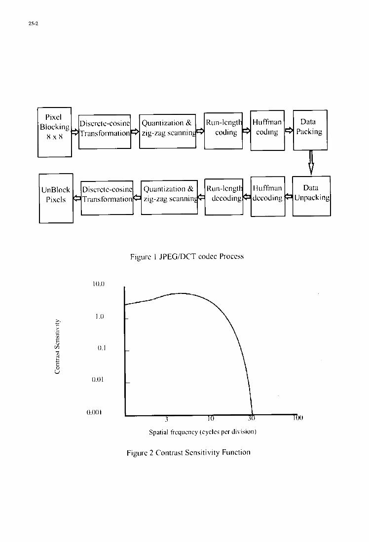
25-2
-- U n Block D isc rc t c-cos i nc Quan t i zat ion & Run - lcngt I- H 11 ffman Data
Pixcls 6 Transformation6 zig-zag scanninLe dccoding dccoding ,b Unpacking
-
n Discrctc-cos1 nc Transformation
Pixcl Blocking H x H zig-zag scannin
Figurc I JPEWDCT codcc Proccss
10.0
1 .o
0. I
0.01
0.001 I 3 I O 3 0 ih
Spatial ti-cqucncy (cyclcs pcr di\%ion)
Figiirc 2 Contrast Scnsitivity Function
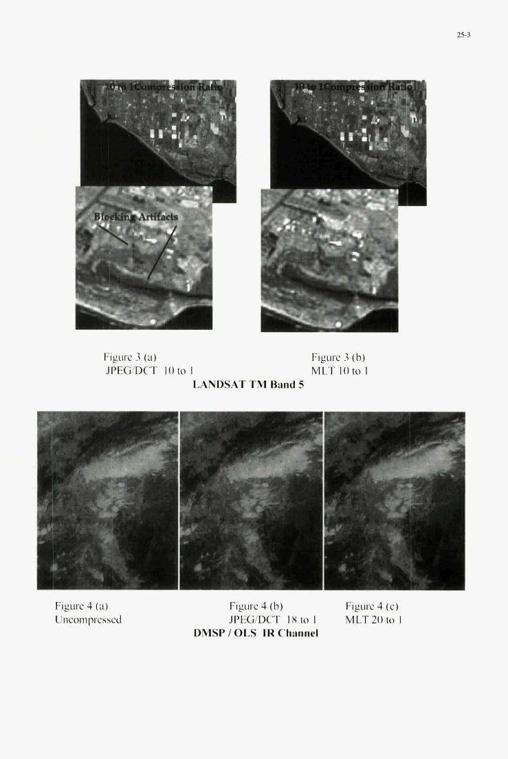
25-3
c I f
Figure 3 (a) Figure 3 (b) JPEG/DCT I O to 1 MLT IO to I
LANDSAT TM Band 5
Figure 4 (a) Figurc 4 (b) Figtirc 4 ( e ) Uncomprcsscd JPEG/DCT I X to I MLT 20 to 1
DMSP / OLS IR Channel
2 5 4
uses an overlapping block architecture and the DCT transform has been replaced by a hybrid transform, the Modified Lapped Transform (MLT). The modified lapped transform is a special type of suhhand filter hank that has been used in many branches of signal processing. At high compression ratios the MLT substantially reduces blocking amfacts. Figure 3@) shows the same portion of a LANDSAT hand, after MLT IO to 1 compression. The reduction of hloeldng artifacts is achieved hy the MLT codec architecture which employs overlapped windows. The image quality obtained from the MLT is not only superior to the JPEG I DCT hut MLT image quality is also superior to other suhhand filters. The increase in MLT image quality is related to preservation of some high frequency information. Based on inspection by several analysts, including a trained photo inte-preter, the visual quality of the MLT was judged superior to the PEG I DCT using a variety of image sources, which had been compressed at several high compression ratios (8 to I , 10 to 1 and 20 to I) .
Image Quality based on Machine Exploitation The visual inspection can be used only as part of the wdec optimization criteria As the amount of image data increases there will also be increases in the machine processing of imagery. For our study we will present comparisons related to several types of automated algorithms which might typically be used by the military to exploit image data sets.
A large class of detection and automated classification techniques rely on brightness thresholding to identify areas of interest within an image. For these techniques, preservation of the pixel digital count is of the utmost importance. To measure the effect of our codec systems on this class of algorithms we examine rwt-mean square (RMS) errors. Table 1 is a compilation of RMS errors for a variety of image data types which have been compressed at a number of different rates. The MLT codec system has produced lower mot-mean squared errors when compared to P E G I DCT for cases with the same compression ratios.
Another important example of machine exploitation is terrain categorization (TFRCAT). A TERCAT is an image derived from sorting multispectral pixels into a number of categories. The pixels are clustered into groups representing different terrain types and land covers. A TERCAT is the automated counterpart to a number of Intelligence Preparation of the Battlefield (IFB) products. The TERCAT generatlon process is subject to performance degradations that are related to mme aspects of wdec system performance.
To evaluate our CodeCS we performed unsupervised classifications on a five hand subset of a multispectral LANDSAT scene. The unsupervised training was used to group pixels with similar spectral characteristics into classes on the basis of statistical patterns that are inherent in the data. The results of the classifications are compared to the original uncompressed image categories. The MLT compressed image has an 89% accwacy ( pixels classed the same as the original xene) and the JPEG has an 81% accuracy. These cases are based on the independent compression, at a ratio of IO to I , of a five hand subset of the LANDSAT scene.
Another automated analysis which was examined is derived from algorithms used for cloud detection and typing U]. For this analysis, satellite sensor data from the Defense Metwrological Satellite Program I Operational Linescan System (OLS) was used. These image data sets consist of dual band images, collected from the infrared (IR) and visible (VIS) channels. The cloud scene data has very different attributes when compared to the LANDSAT scene. For example, the cloud scene has no linear features and channel brightness values span a range more than twice the dynamic range of LANDSAT hand brightness values. The VIS image is originally colleeted at 6 hits per pixel, subsequent processing of the VIS channel expands the data to 8 hits per pixel. This dynamic range expansion results in an uneven histogram with pcaks of high frequency noise. These differences in image types and exploitation algorithms will provide some insight into the suitability of our codec system across a range of applications
For this application cloud typing is accomplished in two stages. The first stage, used primarily for detection, analyzcs the two dimensional IR and VIS hands, with U
priori knowledge of the underlying terrain typing, to divide pixels into nine classification regions. A combination of thresholds and ~ l e s are used to classify pixels into the nine bins. which are used to produce a cloud mask. The second stage of eloud typing uses the cloud mask from stage 1 and the raw IR image to stratify the clouds into layers. Formation of the layers is based on unsupervised classification of the IR pixel values. Pixels within a layer are clustered to form contiguous cloud regions. The size of regions of connected pixels within a layer is used for cloud type determination. The cloud pixels are classed as either cumuliform or stratiform.
For this study the OLS scene was compressed at several high compression ratios, which ranged from 8 to 1 to 20 to 1. The cloud typing results are reported in Table 2. In this instance, there were only marginal changes in classification accuracies for the different compression rates and systems. The classification results may be related to the introduction of high frequency noise in the visible channel. For this reason, we plan to continue investigations with this data set to include compression and classification of image data sets with the VIS data represented in the 6 hit collection values. The modest loss in cloud typing accuracy suggests the consideration of very aggressive compression schemes with this data. The 20 to I compression ratios also did not appear to have a severe effect on visual quality. A visual comparison of the on@ IR hand (Figure 4a). with the 20 to 1 wdec results from JPEG I DCT (Figure 4h) and MLT (Figure 4c) is given.
SPACE BASED COMPRESSION/DECOMPRESSION SYSTEMS: Hardware lmplementatlon W e have shown that transform coding compression systems retain image quality at high compression ratios. The challenge is to design and build a compression system for space with the quality required for intelligence products. Currently the only space based ccdec system which utilizes transform coding is a system based on the PEG DCT. For space implementations, the MLT wdec requires a fast method of implementing Modulated Lapped Transforms. One fast method of implementing a MLT is to decompose
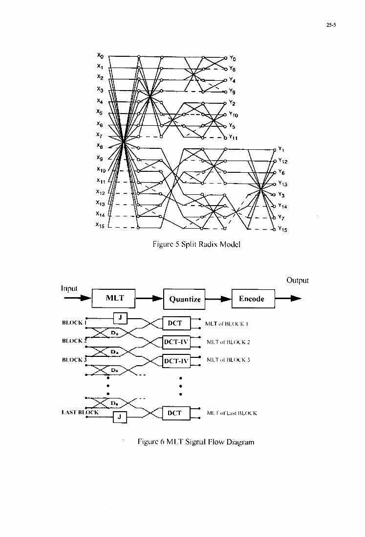
25-5
Figiivc 5 Split Radix Modcl
Y1
y12
'6
y13
y3
'14
Y?
y15
011 tpll t
Figurc 6 MLT Signal Flow Diagram
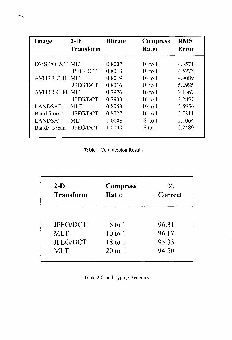
25-6
Image 2-D Bitrate Compress RMS Transform Ratio Error
DMSP/OLS T MLT JPEG/DCT
AVHRRCHI MLT JPEG/DCT
AVHRRCH4 MLT JPEG/DCT
LANDSAT MLT Band 5 rural JPEG/DCT LANDSAT MLT Band5 Urban JPEG/DCT
0.8007 0.8013 0.80 19 0.80 I6 0.7976 0.7903 0.8053 0.8027 1.0008 1.0009
l o t o 1 lo to 1 10to 1 l o t o 1 IOto 1 lo to I 10to 1 IOto 1 8 to I 8 t o 1
4.357 1 4.5278 4.9089 5.2985 2.1367 2.2857 2.5956 2.731 I 2.1064 2.2489
Tablc I Comprcssion Rcsults
2-D Compress Yo Transform Ratio Correct
JPEG/DCT 8 to 1 96.3 1 MLT 10to 1 96.17 JPEG/DCT l8 t0 1 95.33 MLT 20 to 1 94.50
Tablc 2 Cloud Typing Accuracy
25-7
the MLT into a butterfly bank followed by DCT blocks. This process has been described in a number of publications [6,7,81.
A fast DCT processor designed according to the Split-Radix, invented and patented by H.S. Hou [9] has been used for all compression labeled previously as the MLT codec. The patented Split-Radix DCT and the signal flow diagrams of the butterfly MLT for 8 bit inputs are shown in Figures 5 and 6. We have used the fast MLT and DCT methods to process image data on a general purpose computer and on a programmable digital signal processor. We are working to tailor the method for VLSI chip implementations. Based on recently developed algorithms and architectures, we have found methods for designing the forward and inverse MLT with limited interconnects. Decreasing the number of interconnects saves valuable silicon areas in a VLSI chip and simplifies the layouts and routing design. A high speed pipelined architecture for MLT compression and decompression has been implemented with Field Programmable Gate Arrays (FPGA). A prototype PC board containing these FPGA and memory chips has been built at The Aerospace Corporation. The design of a space ready MLT codec system with Application Specific Integrated Circuits (ASIC) is about to commence.
CONCLUSION As NATO increasingly utilizes image data, the importance of optimized compression / decompression schemes will expand. Image data from satellites to cockpits will utilize codecs for the timely delivery of large data sets. Codecs will facilitate image data transfers and if the systems are selected with consideration given to operational processing we will provide time critical information to all NATO forces. The MLT codec provides a system which optimizes compact hardware packaging, a reliable compression scheme, visual quality , low bit rate transmissions , and preservation of image details required for machine exploitation.
ACKNOWLEDGMENTS We thank the DMSP Program Office for the use of their image data. We also wish to thank Mr. Ed Casey and Dr. Craig Lee for processing the DMSP images.
REFERENCES [ 11 J.B. O’Neal, Jr., “Predictive Quantization Systems (Differential Pulse Code Modulation) for the transmission of Television Signals”, BSTJ,Vol. 45, May-June 1966.
[2] R. H. Bosworth and J.C. Candy, “ A compounded one-bit coder for PICTUREPHONE transmission”, BSTJ, Vol. 48, May 1969.
[3] A. Habibi, and P.A. Wintz, “Image coding by linear transformation and block quantization”, IEEE Trans. on Comm., Vol. COM-19, February 1971.
[4] B.A. Wandell, Foundations of Vision, pp 11 1-152 Sunderland Mass, Sinauer Associates Inc., 1995.
[5] G.B. Gustafson, etal, “Support of Environmental Requirements For Cloud Analysis and Archive (SERCAA): Algorithm Descriptions”, Scientific Report No. 2 Phillips Lab, Hanscom Air Force Base, MA, Mar 1994
[6] H. S. Malvar, Signal Processing with Lapped Transforms, Norwood, MA: Artech House, 1992.
[7]. H. S. Malvar, “Extended lapped transforms: properties, applications and fast algorithms”, IEEE Transactions on Signal Processing, vol. 40, pp.2703-2714, Nov. 1992.
[8] M. Temerinac and B. Elder, “Overlapping block transform: window design, fast algorithm, and an image coding experiment,” IEEE Transactions on Communications, vol. 43, pp. 2417-2425, Sept. 1995.
[9] H. S. Hou, “Split-Radix Discrete Cosine Transform,” U.S. Patent 5,408,425, April 18, 1995.

i
26-1 I
RESULTS OF GLOBAL POSITIONING SYSTEM GUIDANCE PACKAGE (GGP) TECHNOLOGY DEMONSTRATION
B. Kaspar, Maj. USAF J. Aein, RAND
A. Killen, MICOM N. Dahlen, Litton
ARPmactical Technology Office - TTO 3701 N. Fairfax Dr.
Arlington, VA 22203-1714, USA
I. INTRODUCTION
The Advanced Research Projects Agency (ARPA) began a program in May 1983 to demonstrate the necessary solid-state technologies to miniaturize full military precision (P/Y) GPS receivers. The ”Virginia Slims” miniature GPS receiver (MGR) program was successfully completed in December 1989 with the demonstration of an MGR the size of a cigarette package. Military products derived from the “Virginia Slims” MGR chip set include the Tomahawk Land Attack Missile GPS receiver, the Precision Location GPS Receiver (PLGR), and the Miniature Airborne GPS Receiver (MAGR), as well as several commercial GPS “engines (e.g., Navcore, Tracker).
Expanding on the success of the achieved miniatur- ization, ARPA initiated the GGP program [1,2] to develop and demonstrate technologies for a new generation of affordable, all solid-state miniature navigation units. Phase 1 of the GGP Program was initiated in 1990. Under a contract awarded to a prime/subcontractor development team of Litton Industries and Rockwell-Collins, two Phase 1 brassboard GGP units were developed. The Phase 1 brassboards are 295 cubic inches in volume, weigh 15 pounds, and draw 31.8 watts of power. The GGP tightly couples the direct sensor outputs from a 10-channel MGR and a miniature inertial measurement unit (MIMU). A real time data pro- cessor provides the tightly coupled integration as well as system alignment, mode control, and navi- gation computation functions. The objective of the follow-on Phase 2 effort is to develop a smaller GGP package (7 lb, 100 cubic inch, 20 watt) while meeting more stringent military environmental re- quirements.
The three principal subsystems of the GGP are the MGR and MIMU kinematic sensors, together with the 26 state, real time Kalman Filter hosted on a digital processor (DP). The MGR is a direct descendant of the original two-channel “Virginia Slims” MGR. The MIMU is composed of three axes, each having a miniature linear accelerometer and an interferometric fiber optic gyro (IFOG)
rotation rate sensor to provide navigation grade of performance. In addition to providing the navigation solution once a second, the GGP also outputs velocity, acceleration, and rotation rate data needed by the host vehicle. The subsystem structure is shown in Figure 1. The MIMU performance goals and contractor results of the GGP Phase 1 are summarized in Table 1.
The two GGP Phase 1 brassboards were demon- strated using the M981 FIST-V as a test platform. The FIST-V, shown in Figure 2, is a fully tracked armored vehicle carrying a laser range finder to geolocate targets for field artillery indirect fire support. The FIST-V combines the azimuth and el- evation (az-el) angle measurements from its laser telescope with the laser determined target range to obtain precise position of the target relative to the FIST-V. Relative target position when combined with accurate location of the FIST-V itself (e.g., GPS/PLGR) is then translated into the appropriate Universal Transverse Mercator (UTM) coordinates and radioed back to the indirect fire con- trol/director.
The precision az-el laser telescope angles are mea- sured using a mechanical (air-bearing, spinning mass) gyroscope referred to as a North Seeking Gyro (NSG). The NSG must be realigned every time the FIST-V comes to a halt to “engage” (i.e., geolocate) a target. A meaningful amount of time (minutes) is consumed during the NSG alignment; thus, extending the engagement time, reducing the number of targets engageable, and increasing the possible exposure time of the FIST-V to counterfire by the enemy.
Two FIST-Vs supported the controlled field demonstration. In FIST Vehicle 1, a GGP Phase 1 brassboard unit replaced the FIST-V North Seeking Gyro (NSG) in the targeting head. In Figure 3, a side-by-side comparison of the NSG and GGP is provided. The GGP was interfaced to the FIST Mis- sion Equipment (FME) via the Targeting Station Control and Display (TSCD). The control FIST Ve- hicle 2 conformed to the operationally fielded sys-
Paper presented at the AGARD MSP 5 I h Symposium on “Space Systems as Contributors to the NATO Defence Mission”, held in Cannes, France, 3-6 June 1996, and published in CP-580.
26-2
tem configuration except that it was also equipped with a handheld PLGR to provide vehicle self-loca- tion data. The two vehicles were operated in tan- dem to allow for a side-by-side comparison of the results.
11. TEST RANGE AND DEMONSTRATION CONDITIONS
The goals of the demonstration were to develop a set of statistically meaningful data on both the GGP-equipped FIST-V and the conventional, NSG- equipped FIST-V. The demonstration test was con- ducted by three different FIST-V military operators, none of whom had any prior exposure to GGP. The primary data obtained were as follows: (1) tar- geting accuracy (and its az-el components) and (2) target engagement time. Additionally, GGP data were taken for (3) integrated GPS/INS navigation accuracy over a surveyed route and (4) free-inertial performance (no GPS) for a ten-minute interval in a FIST-V dynamic environment. Table 2, below, summarizes the demonstration performance goals and the statistically averaged results.
The demonstration was conducted at Redstone Technical Test Center’s Missile Flight Range, Test Area 1 (TA-1) at Redstone Arsenal, Alabama. Tar- gets, Firing Points, and Navigation Points were sur- veyed to within 0.1 meters Spherical Error Probable (SEI’) and delimited with barriers to ensure posi- tion repeatability. In addition, a surveyed point outside of TA-1 was used to initialize the systems and provide a reference point to determine the GGP’s ability to maintain positioning accuracy fol- lowing the transit to the test range. The demon- stration was conducted during daylight hours on June 10 and 12,1995. The majority of the data was taken during the first day, when the ambient conditions exceeded 90 degrees F. The measured temperature within the FIST-V equipment bays containing the GGP and NSG exceeded 130 degrees F. During transit of the FIST-Vs to the test range, the equipment was subjected to average integrated vibration levels in excess of three Gs. The overall test environment was considered to be consistent with combat vehicles operating over rough terrain in a warm climate. Neither the GGP nor NSG suf- fered any failures, despite the heat and vibration.
A map of the test area, with the driving course route and surveyed reference points and targets is shown in Figure 4. Two firing points (FPs), located approximately 200 meters from one another, were used as the reference points from which targets were located. The three surveyed targets were sal- vaged ground vehicles typical of enemy tanks, mis- sile launchers or armored personnel carriers that might be designated with the FIST-V Range Finder.
These targets were located between 1000 and 3750 meters downrange, were at different relative eleva- tions, and were separated in angle by at least 800 mils (total). Targets were marked with an aiming reference point clearly visible through the FIST-V sighting system from both firing points.
A course was laid out with five (5) navigation points (NPs) located approximately two (2) kilome- ters apart. These points were surveyed to within 0.1 meters SEP. The navigation points (Figure 4) were identified by railroad ties placed along the route segments. The vehicles were driven on the navigation course at planned speeds of 18-20 miles per hour between the surveyed points. A portion of the navigation course was also used for the demonstration of the GGP navigation performance in an inertial-only mode (i.e., the MGR was dis- abled by disconnecting the GPS antenna). The shortened, ten-minute course was traversed in the same manner above, but navigation and position- ing data were based on MIMU measurements only.
111. ERROR DETERMINATION
The FIST-V self-location and target location error data were obtained by differencing the NSG or GGP systems’ output and the surveyed values. The errors in both Northings and Eastings were de- termined; and the square root of the sum of the squares of the Northings and Eastings errors formed the amplitude of the horizontal error. The median of the amplitude error is comparable to the Circular Error Probable (CEP) because 50 percent of the data lies within this value.
The errors in self-location were part of the total er- ror budget for target location errors. The targeting and pointing errors were derived in much the same way that self-location errors were. The ”true” tar- get location and pointing values were calculated based on the known (surveyed) positions of firing points and targets and the lever arms for the sen- sors.
Demonstration data were analyzed using an order statistics approach. The data were arranged in as- cending/descending order, with the value of the midpoint of the array being the median. The me- dian is comparable to the average value if the data are symmetric. There is a major advantage to using the median. Since it is not affected by the value of outliers, it is considered to be a more robust statis- tic.
In addition to determining accuracy relative to the presurveyed fixed points, the navigation accuracy of the GGP-equipped vehicle was determined while it was in motion. An Ashtech 2-12 Differen-
26-3
tial GPS (DGPS) instrumentation was used as the reference system for determining the GGP accuracy during the demonstration. The Ashtech system provides position accuracies of better than one me- ter and velocity accuracies to 0.1 m/s. The refer- ence system had three elements which recorded data simultaneously throughout the test period:
A fixed base station was located on a sur- veyed point near the range. It ran throughout the demonstration recording its data to a portable computer.
A roving receiver was installed in the GGP- equipped FIST-V vehicle. Data from this re- ceiver were recorded on a dedicated com- puter inside the vehicle. The roving receiver used its own GPS antenna that was separate from that used by the GGP.
A third personal computer, also inside Vehi- cle 1, recorded the data generated by the GGP.
The data of interest include the following:
Target engagement time; both vehicles (GGP and NSG)
Target location accuracy; both vehicles
Inertial navigation accuracy; Vehicle 1 (GGP)
IV. DEMONSTRATION RESULTS
A. Target Engagement Time
Repeatedly, three separate targets were geolocated by both vehicles from two separate locations (”firing” points) on the laser range. The most dra- matic performance gain in the GGP-equipped FIST- V over that of the NSG-equipped vehicle resulted from the capability of the GGP’s inertial compo- nents to maintain precise stability after the GGP was first initialized at the beginning of a mission. The GGP-equipped vehicle could engage the tar- gets immediately upon arrival at each firing point. In contrast, every time that the NSG-equipped FIST-V stopped at a firing point, on the order of 7- 1/2 minutes were required for the NSG to stabilize. The average engagement time data, summarized in Figure 5, show almost a fourfold reduction in en- gagement time using the GGP.
B. Target Location Errors
Both the GGP and NSG far exceeded the target lo- cation performance goal of 40 meters. A graphical comparison of the average performance obtained
(see Figure 6) is less than this value. Figure 7 pro- vides a comparison of all target location errors (NSG and GGP).
Only those biases associated with the GGP installa- tion could be minimized. Additional, uncompen- sated bias resulted from physical factors within the Laser Range Finder Assembly as well as the man- ner in which the gunner laid the crosshairs across the target. This experiment did not allow the indi- vidual sources of error to be isolated and evalu- ated. The systems were boresighted in the field en- vironment and no experiments were conducted to determine systematic errors.
From the target location error data shown in Figure 7, the GGP has a CEP value of 6.4 meters and the NSG has a CEP value of 8.9 meters. Both are well within the performance goal of 20 meters CEP. Note that the GGP data are more statistically signif- icant since a larger number of data points were ob- tained (more than three times that of the NSG).
Figure 8 is the scatter diagram for the pointing er- rors of the GGP and NSG vehicles. The angles in elevation and azimuth were measured and contain a small amount of residual bias in both angular di- rections. In both vehicles the pointing errors were within the requirements.
C. Inertial Navigation System Test
In order to test the GGP’s free inertial performance, a test was conducted with the GPS antenna discon- nected, effectively disabling the MGR portion of the system. The vehicle was then run over a por- tion of the navigation course, and ”INS-only” self- location data were recorded at the surveyed navi- gation points.
The GGP-equipped FIST-V was operated for more than 20 minutes with the MGR disabled, and the results are shown in Figure 9. The resulting plot shows that at ten minutes (600 seconds), the total error was approximately 20 meters-well within the GGP specification of 100 meters accuracy after ten minutes.
D. Tactical Exercises
Enumerated below are a set of features demon- strated by the GGP-equipped vehicle not covered by the formal procedures of this demonstration.
Camouflage Net. A radar camouflage net was placed over the GGP-equipped FIST-V. The num- ber of satellites and the signal strength were moni- tored both before and after the net was in place. During both sets of tests, six satellites were tracked
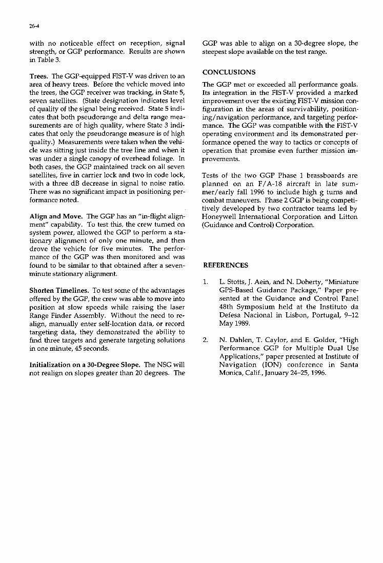
26-4
with no noticeable effect on reception, signal strength, or GGP performance. Results are shown in Table 3.
Trees. The GGP-equipped FIST-V was driven to an area of heavy trees. Before the vehicle moved into the trees, the GGP receiver was tracking, in State 5, seven satellites. (State designation indicates level of quality of the signal being received. State 5 indi- cates that both pseudorange and delta range mea- surements are of high quality, where State 3 indi- cates that only the pseudorange measure is of high quality.) Measurements were taken when the vehi- cle was sitting just inside the tree line and when it was under a single canopy of overhead foliage. In both cases, the GGP maintained track on all seven satellites, five in carrier lock and two in code lock, with a three dB decrease in signal to noise ratio. There was no significant impact in positioning per- formance noted.
Align and Move. The GGP has an “in-flight align- ment” capability. To test this, the crew turned on system power, allowed the GGP to perform a sta- tionary alignment of only one minute, and then drove the vehicle for five minutes. The perfor- mance of the GGP was then monitored and was found to be similar to that obtained after a seven- minute stationary alignment.
Shorten Timelines. To test some of the advantages offered by the GGP, the crew was able to move into position at slow speeds while raising the laser Range Finder Assembly. Without the need to re- align, manually enter self-location data, or record targeting data, they demonstrated the ability to find three targets and generate targeting solutions in one minute, 45 seconds.
Initialization on a 30-Degree Slope. The NSG will not realign on slopes greater than 20 degrees. The
GGP was able to align on a 30-degree slope, the steepest slope available on the test range.
CONCLUSIONS
The GGP met or exceeded all performance goals. Its integration in the FIST-V provided a marked improvement over the existing FIST-V mission con- figuration in the areas of survivability, position- ing/navigation performance, and targeting perfor- mance. The GGP was compatible with the FIST-V operating environment and its demonstrated per- formance opened the way to tactics or concepts of operation that promise even further mission im- provements.
Tests of the two GGP Phase 1 brassboards are planned on an F/A-18 aircraft in late sum- mer/early fall 1996 to include high g turns and combat maneuvers. Phase 2 GGP is being competi- tively developed by two contractor teams led by Honeywell International Corporation and Litton (Guidance and Control) Corporation.
REFERENCES
1. L. Stotts, J. Aein, and N. Doherty, “Miniature GPS-Based Guidance Package,” Paper pre- sented at the Guidance and Control Panel 48th Symposium held at the Instituto da Defesa Nacional in Lisbon, Portugal, 9-12 May 1989.
2. N. Dahlen, T. Caylor, and E. Golder, “High Performance GGP for Multiple Dual Use Applications,” paper presented at Institute of Navigation (ION) conference in Santa Monica, Calif., January 24-25,1996.
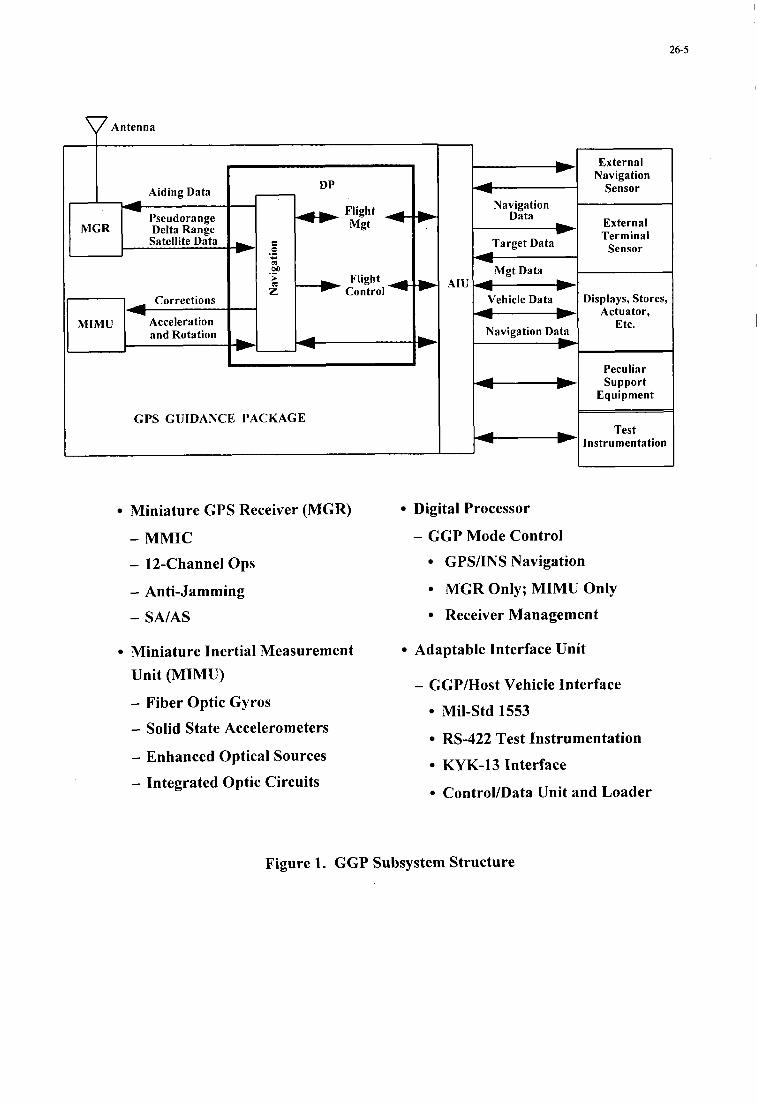
26-5 I
Antenna
Aiding Data
Pseudorange Delta Range Satellite Data
Corrections
Acceleration and Rotation
DP - 4 > m Flight
z Control
GPS GUIDANCE PACKAGE
- Navigation
Data
Target Data
M g t Data
Vehicle Data
Navigation Data
- - - F - -
Miniature GPS Receiver (MGR) Digital Processor
- MMIC - GGP Mode Control
- 12-Channel Ops
- Anti-Jamming
- SA/AS
Miniature Inertial Measurement Unit (MIMU)
- Fiber Optic Gyros
- Solid State Accelerometers
- Enhanced Optical Sources
- Integrated Optic Circuits
External Navigation
Sensor
External Terminal
Sensor
Displays, Stores, Actuator,
Etc.
Peculiar Support
Equipment
Test Instrumentation
GPS/INS Navigation
MGR Only; MIMU Only
Receiver Management
Adaptable Interface Unit
- GGP/Host Vehicle Interface
Mil-Std 1553
RS-422 Test Instrumentation
KYK-13 Interface
ControVData Unit and Loader
Figure 1. GGP Subsystem Structure
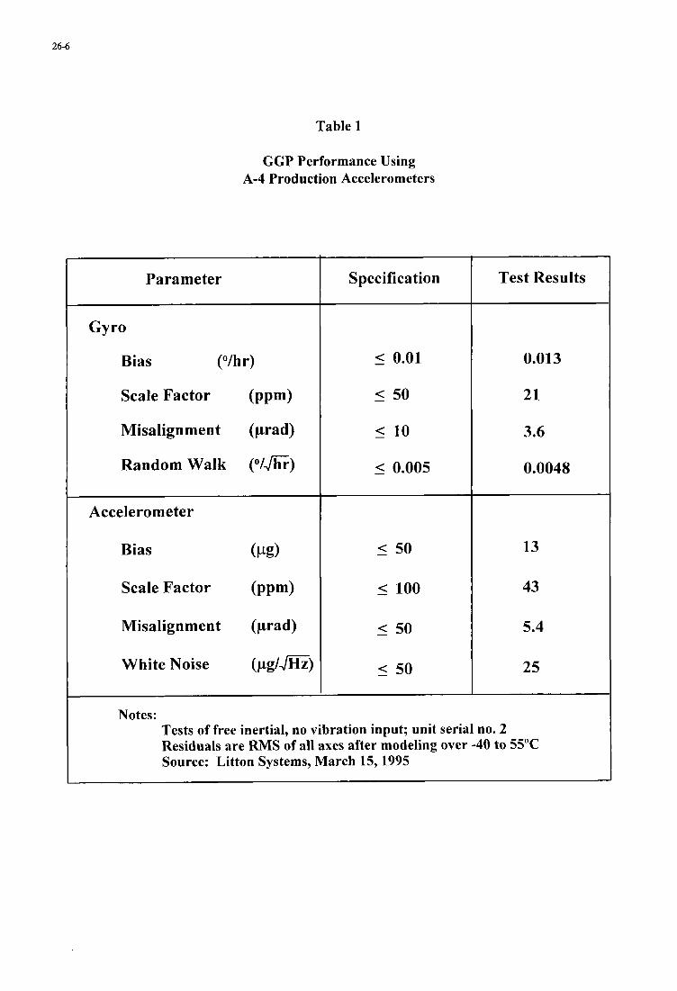
26-6
Table 1
GGP Performance Using A-4 Production Accelerometers
Parameter
Gyro
Bias (“/hr)
Scale Factor (PPW
Misalignment (prad)
Random Walk (“I&)
Accelerometer
Bias (Pg)
Scale Factor (PPm)
Misalignment (prad)
White Noise (pg/J=)
Notes:
Specification Test Results
0.013
21
3.6
0.0048
13
43
5.4
25
Tests of free inertial, no vibration input; unit serial no. 2 Residuals are RMS of all axes after modeling over -40 to 55°C Source: Litton Systems, March 15,1995
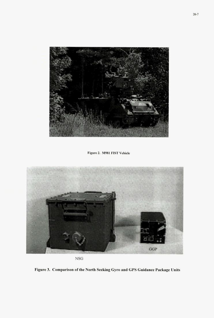
26-7
Figure 2. M981 FIST Vehicle
Flgore 3. Comparison of the North S e w Gym and GPS Guid aekage U&
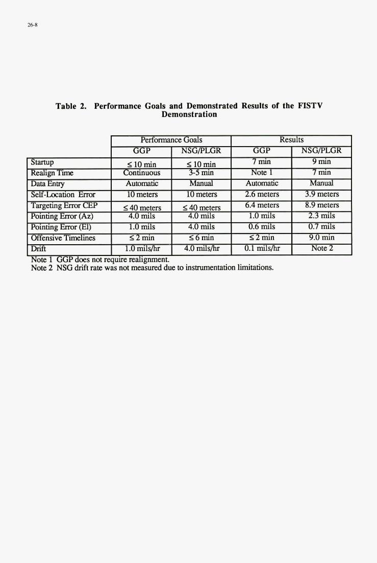
26-8
- ' Pointing Error (El) 1.0 mils 4.0 mils 0.6 m l s 0.7 mils Offensive Timelines s2min 16min s2min 9.0 m n Drift 1.0 mil& 4.0 milsihr 0.1 m i l s h Note 2
Table 2. Performance Goals and Demonstrated Results of the FISTV Demonstration
6.4meters I 8.9 meters Targeting Ena CEP I s40 meters I 14Ometers I Pointing Error (Az) I 4.0 m i l s I 4.0 mils I 1.0 mils I 2.3 mils
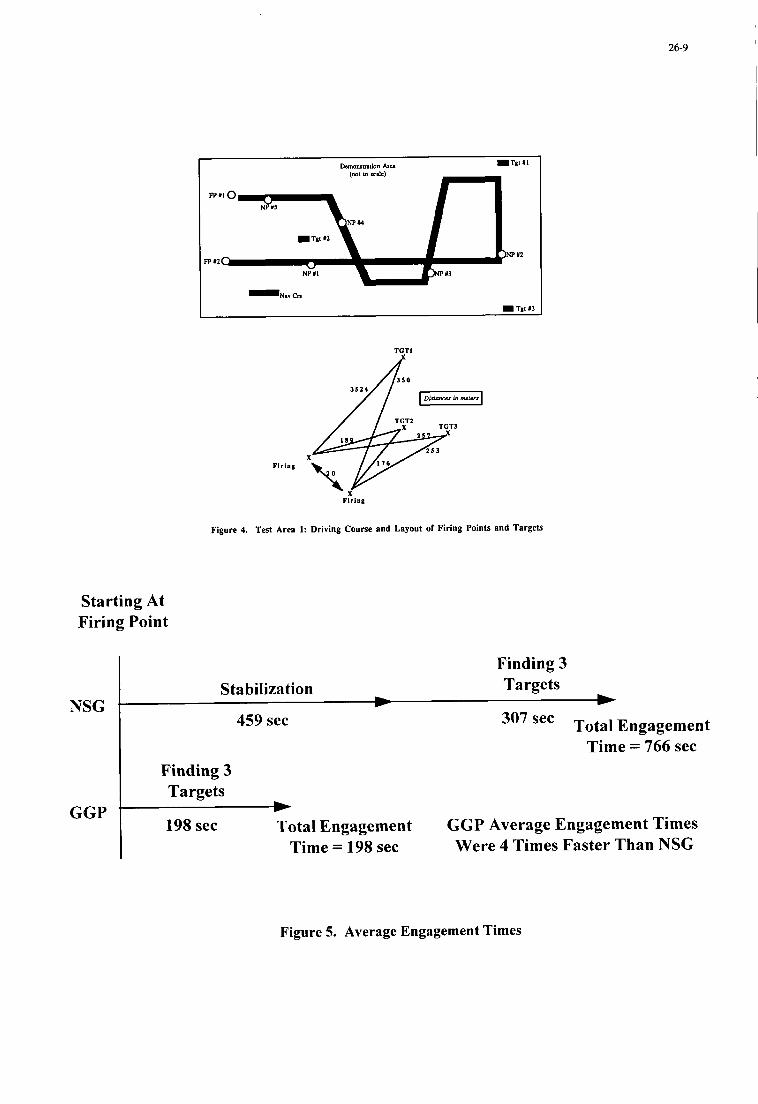
26-9 I
TCTl
Figure 4. Test Area 1: Driving Course end Layout of Firing Points and Targets
Starting At Firing Point
NSG
GGP
Finding 3 Stabilization Targets
L v
307 sec Total Engagement 459 sec
Time = 766 sec Finding 3 Targets
198 sec Total Engagement GGP Average Engagement Times Were 4 Times Faster Than NSG
LL
Time = 198 sec
Figure 5. Average Engagement Times
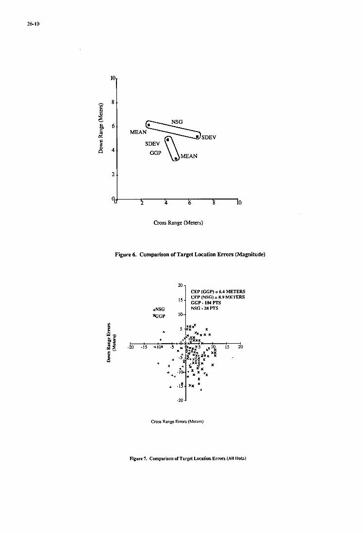
26- 10
1 5 -
+NSG xCGP 10-
2 ;1 '6 k io
Cross Range (Meters)
CEP (GGP) = 6.4 METERS CEP (NSC) = 8.9 METERS GGP-104PTS NSG - 28 ITS
Figure 6. Comparison of Target Location Errors (Magnitude)
Cross Range Errors (Meters)
Figure 7. Comparison of Target Location Errors (All Data)
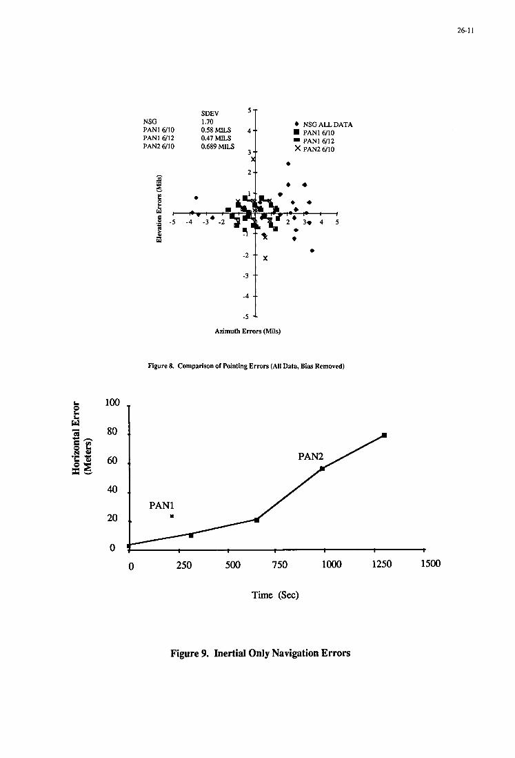
26-1 1
SDEV 5 T
40
20
0
4 NSGALLDATA NSG 1.70 PANl 6/10 PANl 6/12 PAN2 6/10
PANl 6/10 0.47 MILS PANl 6/12 0.689 MILS x PAN2 6/10
Azimuth Errors (Mils)
Figure 8. Comparison of Pointing Errors (All Data, Bias Removed)
PANl
t
PANl
t
0 250 500 750 lo00 1250 1500
Time (Sec)
Figure 9. Inertial Only Navigation Errors
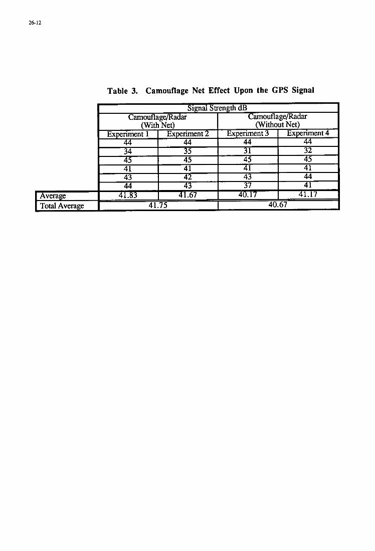
26-12
Table 3. Camouflage Net Effect Upon the GPS Signal
28- 1
FUTURE SPACE TRANSPORTATION SYSTEMS AND THEIR POTENTIAL CONTRIBUTION TO THE NATO MISSION
Chester L. Whitehair and Malcolm G. Wolfe The Aerospace Corporation
El Segundo, CA 90245-469 1. USA Phone: 1-3 10-336-7560; Fax: 1-3 10-336-0503; E-mail: whitehair@courierl .aero.org
1 . SUMMARY Space systems are now an essential part of military operations and, in the Western World, the reliability and operability of these systems is crucial to the success of the military mission. At the same time, overall western military budgets universally are suffering severe cuts.
Although the Cold War is over, the threat to world peace, if anything, has increased rather than decreased. The threat is also much more difficult to contain. The well-defined, single-source, monolithic threat of the Cold War has been replaced by a multi-source, distributed threat. The questions arise - how has the NATO peacekeeping or warfighting mission changed in response to the new world environment; are the space resources of the Cold War the ones that can be effective in the future; how can dwindling government military budgets be augmented by the use of internationally shared or commercial space assets; and how can emerging space technologies and capabilities, whether developed by the government or the commercial sector, contribute to world peace?
The effective support that space systems can provide to the war-fighter is critically dependent on on-demand, assured access to space. Launch services customers will have, in the next century, a wide choice of launchers to deliver, maintain, and possibly recover their space assets. Large spacecraft will still be dependent on mainline expendable launchers similar to those that exist today; however, more choice will be available. Numerous initiatives are underway world-wide to develop commercial spaceports capable of launching small satellites, possibly from ballistic missile derivatives. The result will be to provide more choice in launch location. There is also an interest in the major spacefaring nations to develop reusable launch vehicles, perhaps developed by private rather than government funding, and perhaps developed as international cooperative endeavors. This paper describes the space transportation systems that are expected to be available in the next century and how they may be applied to meet the peacekeeper’s needs.
2 . INTRODUCTION Overall western military budgets are suffering severe cutbacks, although the United States (U.S.) Department of Defense (DoD) space budget, in recognition of the importance of military space, is expected to rise about 12 percent in fiscal year 1997. Civil space is contracting, as the non-military government sector attempts to off- load more funding responsibility on to the commercial sector; commercial space, which did not exist ten years ago, is expanding rapidly, and in some areas leading in new development and innovation. The military sector, in the light of the end of the Cold War, is still re evaluating its role in the new world order and how to
exploit space assets, whether military, civil or commercial, to meet a globally distributed rather than a monolithic threat.
There is a perception in the United States (U.S.) military command that space has been developed and shaped by functional specialists, not operators.’ It took a warfighting event - Desert Storm - to reveal to the warfighter the potential of space. The warfighter was surprised at what was available for improved battlefield situational awareness, for innovative operational agility, and for vastly improved targeting and damage assessment. Traditionally, military space has been dominated by national-level intelligence, reconnaissance, surveillance, and early warning interests.’ These are functional areas. In the new environment, exemplified by the lessons of the Persian Gulf War, it is clear that military exploitation of space needs operational focus. Command systems were suited to the Cold War era, but demand systems are needed to meet the new threat. This is leading to a review of the roles, missions, and functions of the armed forces.*
A serious concern is that the Western Alliance is not postured to fight more than one major regional conflict at the same time. If the Alliance is to function effectively as peacemaker and peacekeeper, space needs to be exploited by developing a global presence through electronic as well as physical means.3 The changing needs can be summarized as providing:
Global view - making full use of the high ground of
Global presence - augment limited, regional physical
Global reach - world-wide dominance in information
Global power - deliver precision attack munitions
space.
presence with global virtual presence.
warfare.
world-wide, on demand.
Implementation of this doctrine places increased demands on the means to access space.4.
3 . THE CHANGING ROLE OF NATO The proliferation of precision standoff weapon delivery systems was reported by SPACE MAGAZINE in 1992 (See Figure 1) . Even if they have a range of only a few hundred miles, in the hands of warlords these weapons pose a significant menace to both military and civilian targets. Unfortunately, many of the rogue nations (such as Iraq, Iran, Libya and North Korea) have, or arc accumulating arsenals of chemical, biological and possibly nuclear weapons and have, or are acquiring, the missile systems to deliver them. According to DEFENSE NEWS, low intensity conflicts stretch from the Balkans to Southeast Asia, with United Nations (UN) troops serving in 13 locations.6 There are close to 50 private
Paper presented at the AGARD MSP SIk Symposium on “Space Systems as Contributors to the NATO Defence Mission”, held in Cannes, France, 3-6 June 1996, and published in CP-580.
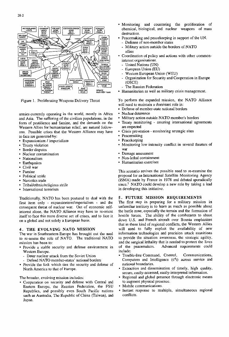
28-2
Figure 1. Proliferating Weapons Delivery Threat
armies currently operating in the world, mostly in Africa and Asia. The suffering of the civilian populations, in the form of pestilience and famine, and the demands on the Western Allies for humanitarian relief, are natural follow- ons. Possible crises that the Western Alliance may have to face are generated by:
Expansionism / imperialism Treaty violation Border disputes Nuclear contamination Nationalism Earthquakes Civil war Famine Political strife Narcotics trade Tribal/ethnic/religious strife International terrorism
Traditionally, NATO has been postured to deal with the first item only - expansionismhmperialism - and the consequent threat of nuclear war. Out of economic self- interest alone, the NATO Alliance may have to re-orient itself to face this more diverse set of crises, and to face it on a global and not solely a European basis.
4 . THE EVOLVING NATO MISSION The war in Southeastern Europe has brought out the need to re-assess the role of NATO. The traditional NATO mission has been to:
Provide a stable security and defense environment in Western Europe. - Deter nuclear attack from the Soviet Union - Defend NATO member-states' national borders
North America to that of Europe. Provide the link which ties the security and defense of
The broader, evolving mission includes: Cooperation on security and defense with Central and Eastern Europe, the Russian Federation, the FSU Republics, and possibly even South Pacific nations such as Australia, The Republic of China (Taiwan), and Japan.
Monitoring and countering the proliferation of chemical, biological, and nuclear weapons of mass destruction.
- Defense of non-member states - Military action outside the borders of NATO
Peacemaking and peacekeeping in support of the UN.
allies 9 Coordination of policy and actions with other common-
interest organizations. - United Nations (UN) - European Union (EU) - Western European Union (WEU) - Organization for Security and Cooperation in Europe
- The Russian Federation (OSCE)
Humanitarian as well as military crisis management.
To perform the expanded mission, the NATO Alliance will need to maintain a dominant role in:
Defense of member-state national borders Nuclear deterrence Military action outside NATO member's borders Treaty monitoring - assuring international agreements are respected Crisis prevention - monitoring strategic sites Peacemaking Peacekeeping Monitoring low intensity conflict in several theaters of
Damage assessment Non-lethal containment Humanitarian exercises
War
This scenario revives the possible need to re-examine the proposal for an International Satellite Monitoring Agency (ISMA) made by France in 1978 and debated sporadically since.7 NATO could develop a new role by taking a lead in developing this initiative.
5 . FUTURE MISSION REQUIREMENTS The first step in preparing for a military mission in unfamiliar territory is to learn as much as possible about the battle zone, especially the terrain and the formation of hostile forces. The ability of the combatants to shoot down U.S. and French aircraft over Bosnia emphasizes that in these kind of regional conflicts, the Western Allies will need to fully exploit the availability of new information technologies and precision attack munitions to provide the situation awareness, the strategic agility, and the surgical lethality that is needed to protect the lives of the peacemakers. Advanced requirements could include:
Trouble-free Command, Control, Communications, Computers and Intelligence ( ~ ~ 1 ) across service and national boundaries. Extraction and dissemination of timely, high quality, secure, easily-accessed, easily-interpreted information. Regional and global presence through electronic means to augment physical presence. Mobile communications. Instant response to multiple, simultaneous regional conflicts.
28-3
Defense against unprovoked ballistic missile attacks on
Rapid neutralization of dispersed, mobile, hostile
Instant jamming of hostile forces' communications. Rapid forward deployment of peacekeeping forces into
Joint and coalition operations. Operational capability in two or more regional conflicts
ground-based assets.
weaponry (aircraft / missiles).
hostile territory.
in far-flung locations at the same time.
Interoperability across service lines, theaters, echelons and national forces is essential for coalition warfare. Space- based information systems therefore will be an inevitable part of future conflict. However, 90 percent of bulk military data passes through commercial channels, subjecting the system to low-cost attack by cyber- terrorists. Traditional methods of gathering and acting on information could become ineffective against this future threat.8 New, innovative systems may be needed.
6 . ACCESS TO SPACE - POST 2000 Ever since the Space Shuttle failed to meet its expectations, numerous august bodies have called for a space transportation system that will provide responsive, inexpensive assured access to space. Satisfying these requirements is not easy, but a new U.S. space transportation policy statement was signed by President Clinton on August 4, 1994.9 This policy is based on the results of extensive national studies by both the National Aeronautics and Space Administration (NASA) and the Department of Defense (DOD). '~ '" The Clinton space transportation policy can be summarized as follows:
Upgrade the performance of the Space Shuttle in the near-term to enable it to perform its Space Station Freedom (SSF) role; but plan to replace it in the far- term. Improve the reliability and cost-effectiveness of the U.S. medium and heavy lift capability by awarding contracts for the development of a DoD-managed Evolved Expendable Launch Vehicle (EELV) family. This would eventually replace the existing Delta, Atlas and Titan launchers for servicing national military, classified, and civil mission models. Embark on a NASA-led Reusable Launch Vehicle (ICV) program to demonstrate a fully reusable system to replace the Space Shuttle in the next century. Encourage innovative government-industry and private sector partnerships to develop a more competitive U.S. commercial space industry. Retain for government use, or destroy, excess ballistic missiles declared surplus by the Treaty between the United States of America and the Union of Soviet Socialist Republics (USSR) on the Reduction and Limitations of Strategic Offensive Arms of July 31, 1991. (Note: This treaty is being subjected to considerable question and interpretation.)
7 . FUTURE SPACE TRANSPORTATION SYSTEMS The Clinton space policy is expected to shape the contribution of the U.S. to the NATO Alliance space transportation needs in the next century. The European
Ariane 5 will also support NATO missions. If political and economic stability is achieved in the FSU and the Russian Federation begins to participate in global peacekeeping, it is possible Russian and Ukranian launchers will also play a beneficial role. Other national systems exist or are coming on line, and could play beneficial or threatening roles, depending on the future world order.'** l 3 Some of the more significant ones are described below.
7 . 1 Upgraded U.S. Space Shuttle Although the high cost of the U.S. Space Shuttle operations detracts from its utility and the NASA Outlook for Space Study called for its replacement, it is expected to be flying well into the next century.1° In order for it to support the International Space Station (ISS), its payload capability is being increased by replacing the current External Tank (ET) with a super-lightweight tank and by making modifications to the Space Shuttle Main Engine (SSME). The design will be frozen after these changes. There are no plans to build additional vehicles.
To reduce the cost per flight, NASA is also making drastic cuts in the number of government and contractor personnel involved in Shuttle operations. Privatization of Shuttle operations has been discussed, but the present plan is to consolidate Shuttle operations under a single sole- source Space Flight Operations Contract (SFOC) with United Space Alliance, a 50-50 joint venture by Lockheed Martin and Rockwell International in order to launch the first Space Station element in December, 1997. Presently, the two companies control almost 70 percent of the current Shuttle operations contracts.
The Space Shuttle has already made several rendezvous flights to the ex-Soviet space station, Mir, and will be expected to deliver 20,000 to 25,000 Ib (9,000 to 1 1,250 kg) to SSF orbit. The first flight to the ISS is planned for 1998.
7 . 2 Upgraded U.S. Expendable Launch Ve hicles The U S . mainline launcher producers, McDonnell Douglas and Lockheed Martin, are taking steps to make their current stables of vehicles more competitive in the commercial market. McDonnell Douglas is planning to field the Delta III; Lockheed Martin is spending $300 million to upgrade the Atlas and the Titan IV families of vehicles. The characteristics of the three upgraded vehicles are illustrated in Figure 2.
7 . 2 . 1 Delta ZZZ McDonnell Douglas has been motivated to develop the Delta I11 (the largest space transportation system ever developed by private funding) by a commitment from Hughes Telecommunications and Space to serve as anchor customer for 10 launches between 1998 and 2002. The two-stage Delta I11 will be capable of placing about 8,400 Ib (3,810 kg) into geotransfer orbit (GTO); the three-stage Delta I1 can launch up to 4,060 Ib (1,840 kg) into GTO. The Delta I11 will use a new high energy single-engined upper stage and longer solid strap-ons than Delta 11. Initial Operating Capability (IOC) is planned for 1997.
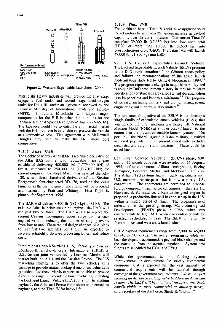
28-4
Titan IVB
LEO Polar 39,000 (17,700) - LEO Due East 18,400 (8,350) - 47,000 (21,300) - GTO 8,400 (3,810) 8.400 (3,810) - 15,000 (6.800) GEO 10,000 (4,530) -
Figure 2. Western Expendable Launchers - 2000
Mitsubishi Heavy Industries will provide the first stage cryogenic fuel tanks and second stage liquid oxygen tanks for Delta 111, under an agreement approved by the Japanese Ministry of International Trade and Industry (MITI). In return, Mitsubishi will import major components for the H-I1 launcher that it builds for the Japanese National Space Development Agency (NASDA). The Japanese would like to enter the commercial market with the H-I1 but have been unable to produce the vehicle at a competitive cost. This agreement with McDonnell Douglas may help to make the H-I1 more cost competitive.
7 . 2 . 2 Atlas IIAR The Lockheed Martin Atlas IIAR is a planned derivative of the Atlas IIAS with a new, throttleable main engine capable of delivering 400,000 Ibf (1,779,400 kN) of thrust, compared to 250,000 Ibf (1,112,100 kN) for current engines. Lockheed Martin has selected the RD- 180, a two thrust-chambered derivative of the Russian Energomash four-chambered RD- 170, used on the &nit launcher as the main engine. The engine will be produced and marketed by Pratt and Whitney. First flight is planned for September, 1998.
The IIAR will deliver 8,400 Ib (3810 kg) to GTO. The existing Atlas launcher uses nine engines; the IIAR will use just two or three. The IIAR will also replace the current Centaur two-engined upper stage with a one- engined version, reducing the number of staging events from four to one. These radical design changes plus plans to manifest two satellites per flight, are expected to increase reliability, decrease processing times, and reduce costs.
International Launch Services (ILS), formally known as Lockheed-Khrunichev-Energia International (LKEI), a U.S./Russian joint venture led by Lockheed Martin, will market both the Atlas and the Russian Proton. The ILS marketing strategy is to offer the two vehicles as a package to provide mutual backup if one of the vehicles is grounded. Lockheed Martin expects to be able to provide a complete range of expendable launch vehicles, including the Lockheed Launch Vehicle (LLV) for small to medium payloads, the Atlas and Proton for medium to intermediate payloads, and the Titan IV for heavy lift.
7 . 2 . 3 Titan IVB The Lockheed Martin Titan IVB will have upgraded solid rocket motors to achieve a 25 percent increase in payload capability over the current system. The current Titan IV can place 39,000 Ib (17,680 kg) into low earth orbit (LEO), or more than 10,000 Ib (4,530 kg) into geosynchronous orbit (CEO). The Titan IVB will launch 47,000 Ib (21,300 kg) into LEO.
7 . 3 U.S. Evolved Expendable Launch Vehicle The Evolved Expendable Launch Vehicle (EELV) program is the DoD implementation of the Clinton space policy and follows the recommendations of the space launch modernization study led by General Moorman in 1994.14 The program represents a change in acquisition policy and is unique in DoD procurement history in that no military specifications or standards are called for and documentation is to be paperless and kept to a m i n i m ~ m . ' ~ The program office size, including military and civilian management, engineering and support, is also limited.
The fundamental objective of the EELV is to develop a single family of expendable launch vehicles (ELVs) that will service the U.S. medium and heavy lift National Mission Model (NMM) at a lower cost of launch to the nation than the present expendable launch systems. The portion of the NMM targeted includes military, classified and civil payloads, but at present specifically excludes crew-rated and cargo return missions. These could be added later.
16
Low Cost Concept Validation (LCCV) phase, $30 million-15 month contracts were awarded on 24 August, 1995, to four contractors: Alliant Techsystems, Boeing Aerospace, Lockheed Martin, and McDonnell Douglas. The Alliant Techsystems team initially included a non- U.S. member - Arianespace - but is now a purely U.S. consortium. The contractors are permitted to propose foreign component, such as rocket engines, if they see fit. However, if, for instance, a Russian-designed engine is proposed, a production line will have to set up in the U.S. within a limited period of time. The program's next milestone is the pre-Engineering, Manufacturing and Development (PEMD) phase in 1966, when two contracts will be let; EMD, when one contractor will be selected, is scheduled for 1998. The EELV family will fly from both east and west coast launch sites.
EELV payload requirements range from 2,000 to 45,000 Ib (910 to 20,400 kg). The overall program schedule has been developed to accommodate payload block changes and the transition from the current launchers. System test flights are scheduled for FYOl and FY03.
While the government is not funding system improvements or development for strictly commercial requirements, i t is expected that the vast majority of commercial requirements will be satisfied through coverage of the government requirements. "We're not just building an Air Force system; we're building an American system. The EELV will be a national resource, one that's equally viable to meet commercial or military needs," said Secretary of the Air Force, Sheila E. Widnall.17
28-5
7 . 4 Non-U.S. Mainline Expendable Launch Vehicles The expanding commercialization of space will increase the number of launchers available for the warfighter.
7 . 4 . 1 Europe The Ariane family of launch vehicles represents Europe's contribution to Western launch capability. The current Ariane 4 family will be gradually replaced by the Ariane 5 during the late 1990s. The Ariane program has clearly demonstrated that international launch vehicle development is feasible.
7 .4 .1 .1 Ariane 5. The Ariane 5 is scheduled for its maiden flight in June, 1996. It will be capable of delivering 13,160 to 15,OO Ib (5,970 to 6,800 kg) to GTO and therefore will be capable of launching two high- powered Hughes HS-601 or Lockheed Martin A2100 satellites at once. The current Ariane 4-44L has a payload limit of 9,810 Ib (4,460 kg) to GTO when two payloads are manifested. The Ariane 4 has been very successful, having captured more than 60 percent of the commercial market.
The Ariane launchers are marketed and operated by Arianespace Inc. On 10 June, 1995, Arianespace signed a $2.4 billion contract with European industry for the first batch of 14 Ariane 5 launchers to cover its needs until the year 2000. The contract is expected to lead to a second batch of 50 launchers. These will be available for commercial, civil and military launches well into the next century.
A planned Ariane 5 upgrade of the payload fairing (Sylda 5) will provide an 880 Ib (400 kg) increase in payload; a second upgrade would redesign the solid rocket motors to permit a further 330 Ib (150 kg) of payload; a third upgrade being considered would involve developing a second-generation Vulcain main engine, increasing the payload capability by a further 1760 Ib (800 kg). An Ariane 6, which could possibly use liquid rocket boosters or be partially recoverable, is only in the very preliminary design phase.
7 . 4 . 2 Russ ia The utility of Russian launchers to the Western Alliance is subject to a number of factors, including the degree of political and economic stability achieved in Russia, the quotas placed by Europe and the U.S. on the number of Russian commercial launches, the various cooperative arrangements that are developing between Russian and Western private industry, and the outcome of various political agreements and treaties that are being negotiated under the auspices of the Organization for Security and Cooperation in Europe (OSCE), the North Atlantic Cooperation Council (NACC), the Treaty on Conventional Forces in Europe (CFE), and the second set of Strategic Arms Reduction Talks (START Il) agreements .
7 . 4 . 2 . 1 Proton. At present, the Proton is launched from the Baikonur Cosmodrome in Kazakhstan. In addition to being marketed by ILS in the West it will also be available as a purely Russian launcher. It can place
46,000 Ib (20,900 kg) into LEO, 12,100 Ib (5,500 kg) into GTO, or 4,850 Ib (2,200 kg) into GEO.
7 . 4 . 2 . 2 Kosmos. The medium-class, two-stage SL-8 Kosmos is now launched solely from the Plesetsk Cosmodrome in Russia, but is the only ex-Soviet launch vehicle to have flown from all three launch sites (Plesetsk, Kapustin Yar, and Tyuratam). It can deliver 2,400 to 3,100 Ib (1,100 to 1,400 kg) into low to medium orbits. Attempts are being made to market it in the West, as discussed below.
7 . 4 . 3 Ukraine Discussions between the U.S. and Ukranian governments concerning the disposition of the Ukranian nuclear arsenal are impacting the availability of Ukranian launchers. Negotiations are underway which would permit the Ukraine to launch a limited number of U.S. commercial satellites through the year 2001. The offer is expected to be similar to the one that allows the Peoples Republic of China (PRC) to launch U.S. commercial satellites.
7 .4 .3 .1 Zeni t . The SL-16 Zenit uses Russian engines but is built by the Yuzhnoye Design Bureau in Dnepropetrovsk, Ukraine, and flies out of Baikonor. The two-stage Zenit delivers 28,700 Ib (13 tonnes) to LEO. Negotiations are going on between Boeing Aerospace and the Ukranians to launch the Zenit as a commercial venture from a floating platform in the Pacific Ocean. The Yushnoye Design Bureau is designing a Zenit payload dispenser to place 12 Globalstar communications satellites into LEO with a single launch in anticipation of commercial business.
7 .4 .3 .2 Tsyklon. The Tsyklon family (SL-11 and SL-14) can deliver up to 7,900 Ib (3,600 kg) to LEO. The SL-14 flies from a highly automated launch complex in Plesetsk, Russia, which minimizes manual activites during launch processing. It was developed by the Yuzhnoye Design Bureau; primary assembly takes place at MZ Yuzhmash in Dnepropetrovsk.
7 . 4 . 4 Peoples Republic of China (PRC) Chinese launchers are strong competitors in the commercial marketplace, since the U.S. government has agreed to allow the PRC to launch 15 to 20 U.S. commercial satellites through December 31, 2001. However, they have had a recent run of spectacular failures.
7 .4 .4 .1 Long March. The Chinese Long March family of vehicles, manufactured by the China Great Wall Industry, presents a strong challenge to the Western launch services providers because of lower cost. Several western satellites have been launched by the Long March and, in spite of reliability problems, more are planned. The Long March 3A can place 5,700 Ib (2,600 kg) into GTO. In spite of three un-diagnosed failures in five attempted flights, Hughes Communications International has not cancelled an agreement which gives i t options for 10 Long March launches over the next four years. China is developing a variant of its Long March 2E (the Long March 2E/TS) to place 12 Globalstarmobile telephone communications satellites into LEO with a
28-6
single launch.
7 . 4 . 5 Japan Although the Japanese government would like to commercialize their H-I1 launcher, the system is currently not cost-competitive. To overcome this, Japan has decided to import foreign components to upgrade the vehicle. Some technology interchange between McDonnell Douglas, Aerojet, Pratt and Whitney, Rockwell International, and some European Ariane subcontractors and the Japanese is being considered which may help the H-I1 become more competitive.
7 . 4 . 5 . 1 H-II. The H-I1 can deliver 23,000 Ib (10,500 kg) to LEO, 8,800 Ib (4,000 kg) to GTO, and 4,800 Ib (2,200 kg) to GEO. Its launch rate is restricted by seasonal launch window constraints imposed by the government.
7 . 4 . 6 India India is an example of a developing nation which is building an autonomous capability in military space. The Bangalore-based Indian Space Research Organization (ISRO) and the Dehradun-based Defense Electronics Research Laboratory (DERL) are working on a range of satellite-based surveillance devices intended to shift the present ground-based intelligence gathering effort to a satellite-based one within the next five years. India has several on-going missile programs (the Agni, Prithvi, Trishul and Akash), and is assumed to possess chemical, biological and nuclear weapons. The Agni IRBM is capable of delivering a 2,200 Ib (1 tonne) warhead more than 1,350 nm (2,500 km).
7 . 4 . 6 . 1 Geostationary Satellite Launch Vehicle (GSLV). The next-generation Indian launcher, the GSLV, will launch about 11,000 Ib (5,000 kg) into LEO or 5,500 Ib (2,500 kg) into GTO. This kind of capability, with its corresponding capability to deliver weapons of mass destruction is expected to proliferate throughout several of the developing nations.
7 . 5 Small U.S. Expendable Launch Vehicles The miniaturization of electronics and lightweight structures are enabling satellites to be reduced in size and yet still perform useful missions. This has resulted in a number of small launch vehicles becoming available on the commercial market.
7 . 5 . 1 Delta Lite The Delta Lite is a McDonnell Douglas launcher sized to meet a NASA requirement for a capability to launch “half the payload of the Delta for half the cost. ‘I Development has been delayed since the cost objective has been found hard to achieve.
7 . 5 . 2 Lockheed Martin Launch Vehicle ( L M L V ) The smallest member of the Lockheed Martin family has flown once, unsuccessfully. When operational, the LMLV commercial launcher is expected to deliver 1,755 to 8,060 Ib (800 to 3,655 kg) to LEO.
7 . 5 . 3 Pegasus XL The Pegasus XL is an Orbital Sciences’ launcher which is launched from a Lockheed L- 101 1 air-breathing launch platform. It has all-azimuth launch capability and can deliver 1,015 Ib (460 kg) to LEO. It is the only operational air-launched Western launcher and can operate from non-U.S. launch sites. It is illustrated in Figure 3. After two failures it finally achieved a successful flight on 9 March, 1996.
7 . 5 . 4 Taurus The Taurus is an Orbital Sciences‘ ground-launched commercial vehicle capable of delivering 3,100 Ib (1,400 kg) to LEO or 2,340 Ib (1,060 kg) to GTO.
7 . 5 . 5 Conestoga The Conestoga family of vehicles is marketed by EER Systems. The largest vehicle can deliver 1,960 Ib (889 kg) to LEO. The maiden flight of the Conestoga was unsuccessful.
7 . 6 Small Non-U.S. Expendable Launch Vehicles Many nations other than the U.S. have shown an interest in developing their own small launchers as a means of achieving autonomy in space or as a means to develop a ballistic missile capability. Some of the more significant are described below.
7 .6 .1 India India has successfully launched its third generation launch vehicle, the PSLV, placing the 1,7770 Ib (804 kg) IRS- P2 remote sensing satellite into a 488 nm x 533 nm (802 km x 875 km) polar sun synchronous orbit. Two small launchers are in current production.
7 .6 .1 .1 Augmented Satellite Launch Vehicle ( A S L V ) . The ASLV can deliver 330 Ib (150 kg) into LEO.
7 .6 .1 .2 Polar Satellite Launch Vehicle ( P S L V ) . The PSLV can deliver 6,400 Ib (2,900 kg) into LEO or 990 Ib (450 kg) to GTO.
7 . 6 . 2 Israel
7 .6 .2 .1 Shavit (Cornet). The Israeli 4-stage Shavit has been proposed as an ultralite launcher capable of delivering 660 Ib (300 kg) to LEO from Vandenberg Air Force Base (VAFB) or greater than 660 Ib to GEO from Wallops Island. Because the OSC Pegasus suffered two failures in succession, TRW proposed using Shavit to orbit the Tri-Service Experiment Mission 5 for the Ballistic Missile Defense Organization (BMDO). At this time, Israel is not a signatory to the Missile Technology Control Regime (MTCR) agreement.
7 . 6 . 3 Russia Numerous small launcher proposals have come out of the FSU since the end of the Cold War. The Burlak is typical.
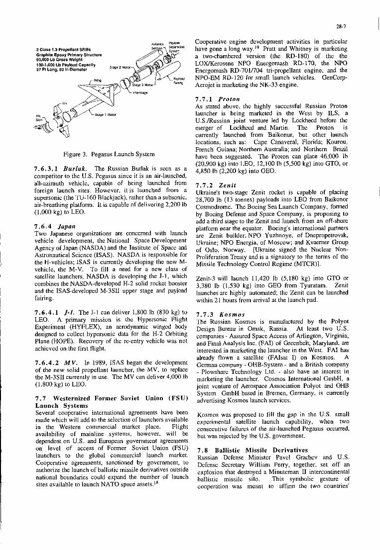
28-7 I
3 Class 1.3 Propellant SRMs Graphite Epoxy Primary Structure 50.000 Lb Gross Welght 100-1,000 Cb Payload Capacity Stage 57 Ft Long, 50 In Dlameter
Aft Skirt-',-
- ' i d ation
Graphite Epoxy Primary Structure 50.000 Lb Gross Welpht
Interstage
Figure 3. Pegasus Launch System
7 .6 .3 .1 Burlak . The Russian Burlak is seen as a competitor to the U.S. Pegasus since it is an air-launched, all-azimuth vehicle, capable of being launched from foreign launch sites. However, it is launched from a supersonic (the TU-I60 Blackjack), rather than a subsonic, air-breathing platform. It is capable of delivering 2,200 lb (1,000 kg) to LEO.
7 . 6 . 4 Japan Two Japanese organizations are concerned with launch vehicle development, the National Space Development Agency of Japan (NASDA) and the Institute of Space and Astronautical Science (ISAS). NASDA is responsible for the H-vehicles; ISAS is currently developing the new M- vehicle, the M-V. To fill a need for a new class of satellite launchers, NASDA is developing the J- 1, which combines the NASDA-developed H-2 solid rocket booster and the ISAS-developed M-3SII upper stage and payload fairing.
7 . 6 . 4 . 1 J - I . The J-1 can deliver 1,800 Ib (830 kg) to LEO. A primary mission is the Hypersonic Flight Experiment (HYFLEX), an aerodynamic winged body designed to collect hypersonic data for the H-2 Orbiting Plane (HOPE). Recovery of the re-entry vehicle was not achieved on the first flight.
7 . 6 . 4 . 2 M V . In 1989, ISAS began the development of the new solid propellant launcher, the MV, to replace the M-3SII currently in use. The MV can deliver 4,000 lb (1,800 kg) to LEO.
7 . 7 Westernized Former Soviet Union (FSU) Launch Systems Several cooperative international agreements have been made which will add to the selection of launchers available in the Western commercial market place. Flight availability of mainline systems, however, will be dependent on U.S. and European government agreements on level of access of Former Soviet Union (FSU) launchers to the global commercial launch market. Cooperative agreements, sanctioned by government, to authorize the launch of ballistic missile derivatives outside national boundaries could expand the number of launch sites available to launch NATO space assets."
Cooperative engine development activities in particular have gone a long way.I9 Pratt and Whitney is marketing a two-chambered version (the RD-180) of the the LOXKerosene NPO Energomash RD-170, the NPO Energomash RD-701/704 tri-propellant engine, and the NPO-EM RD-120 for small launch vehicles. GenCorp- Aerojet is marketing the NK-33 engine.
7 . 7 . 1 Proton As stated above, the highly successful Russian Proton launcher is being marketed in the West by ILS, a U.S./Russian joint venture led by Lockheed before the merger of Lockheed and Martin. The Proton is currently launched from Baikonur, but other launch locations, such as: Cape Canaveral, Florida; Kourou, French Guiana; Northern Australia; and Northern Brazil have been suggested. The Proton can place 46,000 Ib (20,900 kg) into LEO, 12,100 lb (5,500 kg) into GTO, or 4,850 Ib (2,200 kg) into GEO.
7 . 7 . 2 Zeni t ,
28,700 Ib (13 tonnes) payloads into LEO from Baikonor Cosmodrome. The Boeing Sea Launch Company, formed by Boeing Defense and Space Company, is proposing to add a third stage to the &nit and launch from an off-shore platform near the equator. Boeing's international partners are Zenit builder, NPO Yuzhnoye, of Dnepropetrovsk, Ukraine; NPO Energia, of Moscow; and Kvaerner Group of Oslo, Norway. [Ukraine signed the Nuclear Non- Proliferation Treaty and is a signatory to the terms of the
Ukraine's two-stage &nit rocket is capable of placing ~
Missile Technology Control Regime (MTCR)]. ~
Zenit-3 will launch 11,420 Ib (5,180 kg) into GTO or 3,380 Ib (1,530 kg) into GEO from Tyuratam. Zenit launches are highly automated; the Zenit can be launched within 21 hours from arrival at the launch pad.
I
, I
7 . 7 . 3 K o s m o s The Russian Kosmos is manufactured by the Polyot Design Bureau in Omsk, Russia. At least two U.S. companies - Assured Space Access of Arlington, Virginia, and Final Analysis Inc. (FAI) of Greenbelt, Maryland, are interested in marketing the launcher in the West. FA1 has already flown a satellite (FAIsat I) on Kosmos. A German company - OHB-System - and a British company - Plowshare Technology Ltd. - also have an interest in marketing the launcher. Cosmos International GmbH, a joint venture of Aerospace Association Polyot and OHB System GmbH based in Bremen, Germany, is currently advertising Kosmos launch services.
Kosmos was proposed to fill the gap in the U.S. small experimental satellite launch capability, when two consecutive failures of the air-launched Pegasus occurred, but was rejected by the U.S. government.
7 . 8 Ballistic Missile Derivatives Russian Defense Minister Pave1 Grachev and U.S. Defense Secretary William Perry, together, set off an explosion that destroyed a Minuteman I1 intercontinental ballistic missile silo. This symbolic gesture of cooperation was meant to affirm the two countries'
28-8
commitment to nuclear arms reductions mandated by the first Strategic Arms Reduction Treaty (START I), signed in 1991. At the height of the Cold War, the FSU had 2,500 strategic missiles and heavy bombers and the U.S. had 2,250, but under START I, the arsenals will be cut to 1,600 on both sides by December 2001. However, the START I1 agreement of 1993 has not been ratified and is presently under some stress because of Russian concern that NATO is encroaching into Eastern Europe and also the rise of nationalistic sentiment in the FSU. In contrast, the agreement on the disposition of surplus ballistic missiles or their stages is already being subjected to wide interpretation not necessarily in consonance with the Clinton space policy. For instance, Joint Statement Number 21 of the Joint Compliance and Inspection Commission, issued 28 September, 1995, in Geneva, states, "....the first stage of an SS-25 ICBM that is incorporated into a space launch vehicle, designated by the Russian Federation as the START space launch vehicle .... do not result in SS-25 ICBM (derivatives) to be considered ICBMs .... he Treaty does not prohibit a Party from moving ICBM used for delivering objects into .... space .... to a launch facility outside its national territory. " 2o Such statements suggest that a multitude of ballistic missile-derived launchers could find their way on to world markets.
It should be noted that France, Japan and the PRC are not subject to the terms of the treaty. Also, in practice, all space launch vehicles, commercial or military, are derived from ballistic missiles, which leaves considerable leeway for legal debate.
7 . 8 . 1 United States
7 . 8 . 1 . 1 Titan II Space Launch Vehicle ( S L V ) . Lockheed Martin has converted 14 Titan I1 ICBMs to space launchers; about 40 surplus missiles remain in inventory. The Titan I1 can deliver 4,200 Ib (1,905 kg) to LEO.
7 . 8 . 1 . 2 USAF Multiservice Launch S y s t e m (MSLS) Minuteman I I Derivatives. A number of small launch vehicles using Minuteman I1 stages have been proposed for both suborbital and orbital use. Lockheed Martin won a contract in 1992 to develop MSLV for the Space and Missile Systems Center (SMC) at Kirtland AFB, but its use as a space launcher must be approved by the Secretary of Defense. The current schedule calls for three suborbital missions in 1996; orbital flights have not yet been budgeted The suborbital MSLV can carry an 850 lb (385 kg) payload about 4,200 nm (7,800 kg).
Lockheed Martin is restricted from marketing MSLV commercially by the Clinton policy which restricts the use of refurbished missiles for commercial use. However, interpretations of the disposition of surplus ballistic missile agreements are still being made.20 Current plans are to permit the MSLV to orbit five experimental payloads.
7 . 8 . 1 . 3 Polaris / Trident / Poseidon Derivatives. Several small launch vehicles using
surplus Polaris, Trident, or Poseiden submarine-launched ballistic missile (SLBM) stages have been proposed.I2 The availability of surplus hardware will be dependent on the outcome of the START I1 arms reduction treaty.
7 . 8 . 1 . 4 MX (Peacekeeper). Space launchers derived from MX components have also been proposed.12 The START I1 agreements call for the decommissioning of Peacekeeper, but until START I1 is ratified the system will remain operational and therefore not available for conversion.
7 . 8 . 2 R u s s i a
7 . 8 . 2 . 1 Start (SS-25 Sickle Road-Mobi l e ICBM Der iva t i ve ) . The Start vehicles are based on the SS-25 road-mobile ICBM and are launched from an SS-25 mobile launch platform; they are the smallest FSU launchers and also the only ones known to employ all- solid propellants. In theory, they can be launched from any suitable location in the world, providing the country from which the launch takes place is a signatory of the Missile Technology Control Regime (MTCR), although, at this time, flights have only been made from Plesetsk Cosmodrome. They have been offered to a number of countries, including Norway and South Africa, to be flown out of their national spaceports; remote launches would require payload processing, encapsulation, and integration at an appropriate facility before transporting to the launch location. The Australian Space Office is negotiating the launch of the Start from Australia, but is also discussing a joint venture with Russia to develop an industrial base in Australia to build a submarine-launched ballistic missile (SLBM) based launcher called Seagull, and offer commercial launch services from either Woomera or from a location in the Northern Territories.
The Start family of vehicles will deliver up to 1,260 Ib (570 kg) into LEO. The vehicles are marketed by STC Complex, a joint stock company formed in 1991 by the Moscow Institute of Heat Technology (MIHT), the developer of the SS-25.
7 . 8 . 2 . 2 Rokot ( S S - I 9 Stiletto ICBM D e r i v a t i v e ) . The Russian-German Rokot is expected to operate out of Plesetsk Cosmodrome in 1997. The three-stage launcher is based on the Soviet SS-19 ballistic missile and will launch payloads of about 800 to 1,500 kg (1,760 to 3,300 Ib). The vehicle is a product of a team effort between Khrunichev State Research and Production Space Center of Moscow (the primary builder of the Proton rocket) and Daimler-Benz Aerospace's Orbital Systems Division of Bremen, Germany. The marketing company, Eurockot, will be based in Bremen.
7 . 8 . 3 Ukraine
7 . 8 . 3 . 1 Ikar (SS-18 Satan heavy ICBM Der iva t i ve ) . In accordance with the START II agreements, 308 SS-I 8 ballistic missiles are being decommissioned and removed from their silos. The Ikar (1carus)-l and -2 space launchers are derived from the SS- 18 and will be launched from two SS-18 silos at the Baikonur Cosmodrome; it is expected that they will be
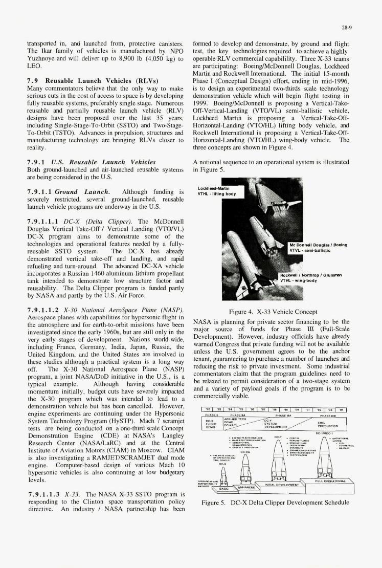
28-9
transported in, and launched from, protective canisters. The Ikar f m l y of vehicles is manufactured by NPO Yuzhnoye and will deliver up to 8,900 Ib (4,050 kg) to LEO.
7.9 Reusable Launch Vehicles (RLVs) Many commentators believe that the only way to make senous cuts in the cost of access to space is by developing fully reusable systems, preferably single stage. Numerous reusable and partially reusable launch velncle (RLV) designs have been proposed over the last 35 years, including Single-Stage-To-Orbit (SSTO) and Two-Stage- To-Orbit (TSTO). Advances in propulsion, structures a d manufacturing technology are bnnging RLVs closer to reality.
7.9.1 US. Reusable Launch Vehicles Both ground-launched and &-launched reusable systems are being considered in the US.
7.9.1.1 Ground Launch. Although funding is severely restricted, several ground-launched, reusable launch vehicle programs are underway in the US.
7.9.1.1.1 DC-X (Delta CIipperj. The McDonnell -Douglas Vertical Take-Off I Vertical Landing (VTO/VL)
DC-X program aims to demonstrate some of the technologies and operational features oeeded by a fully- reusable SSTO system. The DC-X has already demonstrated vertical takeoff and landing, and rapid refueling acd turn-around. The advanced DC-XA vehicle incorporates a Russian 1460 aluminum-lithium propellant tank intended to demonstrate low structure factor ard reusability. The Delta Clipper program is funded partly by NASAand partly by the US. Air Force.
7.9.1.1.2 X-30 National Aerospace P h (NASPj. Aerospace planes with capabilities for hypersonic flight in the atmosphere and for earth-to-orbit missions have been investigated since the early 1960s. but are still only in the very early stages of development. Nations world-wide, including France, Germany, India, Japan, Russia, the United Kingdom, and the United States are involved in these studies although a practical system is a long way off. The X-30 National Aerospace Plane @ASP) program, a joint NASAlDoD initiative in the US., is a typical example. Although having considerable momentum initially, budget cuts have severely impacted the X-30 program which was intended to lead to a demonstration vehicle but has been cancelled. However, engine experiments are continuing under the Hypersonic System Technology Program (HySTP). Mach 7 scramjet tests are being conducted on a one-third scale Concept Demonstration Engine (CDE) at NASA's Langley Research Center (NASAnaRC) and at the Central Institute of Aviation Motors (CIAM) in Moscow. CIAM is also investigating a RAMJET/SCRAMJET dual mode engine. Computer-based design of various Mach IO hypersonic vehicles is also continuing at low budgetary levels.
7.9.1.1.3 X-33. The NASA X-33 SSTO program is responding to the Clinton space transportation policy directive. An industry I NASA partnership has been
formed to develop and demonstrate, by ground and flight test, the key technologies required to achieve a highly operable RLV commercial capabilility. Thme X-33 teams are participating: BoeinglMcDonnell Douglas, L o c W Martin and Rockwell International. The initial 15-month Phase I (Conceptual Design) effort, ending in mid-1996. is to design an experimental two-thirds scale technology demonsbation vehicle which will begin flight testing in 1999. BoeingDAcDonnell is proposing a Vertical-Take- Off-Vertcal-Landing (VTO/VL) semi-ballistic vehicle, Lockheed Martin is proposing a Vertical-Take-Off- Horizontal-Landing (VTO/HL) lifting body vehicle, ad Rockwell International is proposing a Vertical-Take-Off- Horizontal-Landing (VTOML) wing-body vehicle. The three concepts are shown in Figure 4.
A notional sequence to an operational system is illustrated in Figure 5.
Figure 4. X-33 Vehicle Concept NASA is planning for private sector financing to be the major source of funds for Phase III (Full-scale Development). However. industry ofticials have a h d y warned Congress that private funding will not be available unless the US. government agrees to be the anchor tenant, guaranteeing to purchase a number of launches wd reducing the risk to private investment. Some industrial commentators claim that the program guidelines need to be relaxed to permit consideration of a two-stage system and a variety of payload goals if the program is to be commercially viable.
'02 I .m I .Y I ,I5 I (* , I 1. I ,I , I- I m, , N o m E&
I ._ I %.
MrnLII P W I I NIYInI ,*AY,..
~~ D M AWULDTEC"
c€uo w P n m M
*"- r n a D P Y Y I T
_,-I
Figure 5. DC-X Delta Clipper Development Schedule
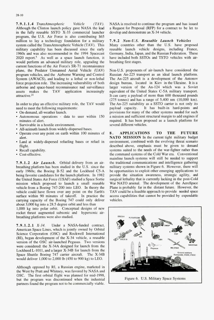
28-10
7.9.1.1.4 TransAmspheric Vehicle (TAV). Although the Clinton launch policy gave NASA the lead in the fully reusable SSTO X-33 commercial launcher program, the US. Air Force is also contributing $65 million to lay a technology foundation for a military system called the TransAtmospheric Vehicle (TAV). This military capability has been discussed since the early 1960s and was also mommendeal in the 1994 Spacecast 2020 report? As well as a space launch function, it would perform an advanced military role, upgrading the current functions of the Air Force's SR-71 reconnaissance plane, the F'redator Unmanned Aerial Vehicle @AV) program vehicles, and the Airborne Warning and Control System (AWACS), and leading to a lethal or non-lethal force projection role. The increasing vulnerability of both airborne and spacebased reconnaissance nad surveillance assets makes the TAV application increasingly attractive.2'
In order to play an effective military role, the TAV would need to meet the following requirements: * On-demand, all-weather launch.
Autonomous owrattons - data to user within 150 I minutes of alert:
Survivable in a hostile environment.
Operate over any point on earth within 100 minutes of alert.
* Land at widely-chspd refueling bases or refuel in flight. Recall capahility.
* All-azimuth launch from widely-dispersed bases.
- Cost-effective.
7.9.1.2 Air Launch. Orbital delivey from an air- breathing platform has been studied in the U.S. since the early 1960s; the Boeing B-52 and the Lockheed C5-A being favorite candidates for the launch platform. In 1982 the United States Air Force (USAF) studied a Space Sortie mission which proposed to launch a small reusable vehicle from a Boeing 747-200 into LEO. In theory the vehicle could have flown over any point on the Earth's surface within 90 minutes of takeoff. In practice the carrying capacity of the Boeing 747 could only deliver about 3,000 kg into a 28.5 degree orbit and less than 1,oOO kg into polar orbit. Conceptual designs of new mcket thrust augmented subsonic and hypersonic air- breathing platforms were also studied.
7.9.1.2.1 X-34. Under a NASA-funded contract, American Space Lines, which is jointly owned by Orbital Science Corporation (OSC) and Rockwell International (RI), began development of the X-34 vehicle, a reusable version of the OSC air-launched Pegasus. Two versions were considered: the X-34A designed for launch from the Lockheed L-101 I , and a larger X-34B for launch from the Space Shuttle Boeing 747 carrier aircraft The X-34B would deliver 1,000 to 2,ooO Ib (450 to 900 kg) to LEO.
Although opposed by RI, a Russian engine, marketed in the West by R a n and Whimey, was favored by NASA and OSC. The first orbital flight was planned for mid-1998, but the program was discontinued when the industrial partners found the program not to be commercially viable.
NASA is resolved to continue the program and has issued a Request for Proposal (RFP) for a contract to be let to develop and demonshate an X-34 vehicle.
7.9.2 Non-U.S. Reusable Launch Vehicles Many countries other than the US. have proposed reusable launch vehicle designs, including France, Germany, India, Japan, and the Russian Federation. These have included both SSTOs and TSTO vehicles with air- breathing frst stages.
Non-U.S. proponents of air-launch have considered the Russian An-225 transport as an ideal launch platform. The An-225 aircraft is a development of the Antonov design bureau, located in Kiev in the Ukraine. It is a larger version of the An-I24 which was a Soviet equivalent of the United States C-5A military transport. It can carry a payload of more than 600 thousand pounds (275 tonnes) and has a range of 5,400 nm (10,000 km). The An-225 suitability as a SSTO carrier is not only its payload capacity. It has built-in hard-points and provisions for many of the other systems needed for such a mission and sufficient shuctural margin to add engines if required. It has been proposed as a launch platform for several different vehicles.
8. APPLICATIONS TO THE FUTURE NATO MISSION In the current tight military budget environment, combined with the evolving threat scenario descrikd above, emphasis must be given to demand systems suited to the needs of the war-fighter rather than the command systems of the Cold War era. Conventional mainline launch systems will still be needed to support the traditional communications and intelligence gathering military systems shown in Figure 6. However, there will be opportunities to exploit other emerging applications to provide the situation awareness, strategic agility, and surgical lethality that is currently lacking in the post-Cold War NATO arsenal. The development of the Aerospace Plane is probably far in the distant future. However, the TAV could be a feasible approach to provide needed space access capabilities that cannot be provided by expendable vehicles.
L b
R
I- Figure 6. U.S. Military Space Systems I
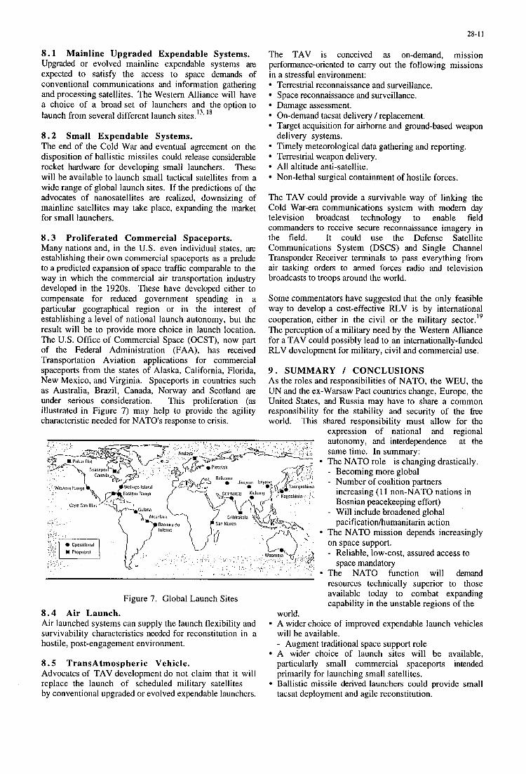
28-1 1
8 . 1 Mainline Upgraded Expendable Systems. Upgraded or evolved mainline expendable systems are expected to satisfy the access to space demands of conventional communications and information gathering and processing satellites. The Western Alliance will have a choice of a broadset of launchers and theoption to launch from several different launch sites.’33 l 8
8 . 2 Small Expendable Systems. The end of the Cold War and eventual agreement on the disposition of ballistic missiles could release considerable rocket hardware for developing small launchers. These will be available to launch small tactical satellites from a wide range of global launch sites. If the predictions of the advocates of nanosatellites are realized, downsizing of mainline satellites may take place, expanding the market for small launchers.
8 . 3 Proliferated Commercial Spaceports. Many nations and, in the U.S. even individual states, are establishing their own commercial spaceports as a prelude to a predicted expansion of space traffic comparable to the way in which the commercial air transportation industry developed in the 1920s. These have developed either to compensate for reduced government spending in a particular geographical region or in the interest of establishing a level of national launch autonomy, but the result will be to provide more choice in launch location. The U.S. Office of Commercial Space (OCST), now part of the Federal Administration (FAA), has received Transportation Aviation applications for commercial spaceports from the states of Alaska, California, Florida, New Mexico, and Virginia. Spaceports in countries such as Australia, Brazil, Canada, Norway and Scotland are under serious consideration. This proliferation (as illustrated in Figure 7) may help to provide the agility characteristic needed for NATO’s response to crisis.
The TAV is conceived as on-demand, mission performance-oriented to carry out the following missions in a stressful environment:
Terrestrial reconnaissance and surveillance. Space reconnaissance and surveillance. Damage assessment. On-demand tacsat delivery / replacement. Target acquisition for airborne and ground-based weapon
Timely meteorological data gathering and reporting. Terrestrial weapon delivery. All altitude anti-satellite. Non-lethal surgical containment of hostile forces.
delivery systems.
The TAV could provide a survivable way of linking the Cold War-era communications system with modem day television broadcast technology to enable field commanders to receive secure reconnaissance imagery in the field. It could use the Defense Satellite Communications System (DSCS) and Single Channel Transponder Receiver terminals to pass everything from air tasking orders to armed forces radio and television broadcasts to troops around the world.
Some commentators have suggested that the only feasible way to develop a cost-effective RLV is by international cooperation, either in the civil or the military sector.’’ The perception of a military need by the Western Alliance for a TAV could possibly lead to an internationally-funded RLV development for military, civil and commercial use.
9 . SUMMARY / CONCLUSIONS As the roles and responsibilities of NATO, the WEU, the UN and the ex-Warsaw Pact countries change, Europe, the United States, and Russia may have to share a common responsibility for the stability and security of the fi-ee world. This shared responsibility must allow for the
expression of national and regional
Figure 7. Global Launch Sites
8 . 4 Air Launch. Air launched systems can supply the launch flexibility and survivability characteristics needed for reconstitution in a hostile, post-engagement environment.
8 . 5 TransAtmospheric Vehicle. Advocates of TAV development do not claim that it will replace the launch of scheduled military satellites by conventional upgraded or evolved expendable launchers.
autonomy, and interdependence at the same time. In summary: The NATO role is changing drastically. - Becoming more global - Number of coalition partners
increasing (1 1 non-NATO nations in Bosnian peacekeeping effort)
- Will include broadened global pacificationhmanitarin action
The NATO mission depends increasingly on space support. - Reliable, low-cost, assured access to
space mandatory The NATO function will demand resources technically superior to those available today to combat expanding capability in the unstable regions of the
world.
will be available. - Augment traditional space support role A wider choice of launch sites will be available, particularly small commercial spaceports intended primarily for launching small satellites. Ballistic missile derived launchers could provide small tacsat deployment and agile reconstitution.
A wider choice of improved expendable launch vehicles
28-12
Air-launched systems could provide greater survivability and perform new functions. - Dispersed launch locations - All-azimuth launch The TransAtmospheric Vehicle (TAV), although having limited advocacy at this time, could fill a critical post- 2000 perceived peace-makindpeace keeping need by providing: - Situation awareness - Strategic agility - Recallable surgical lethality - Immunity to information warfare - Survivable The increasing interdependence between the Western Alliance nations could lead to international development of the TAV becoming a feasible possibility.
There is a need for standardization and cooperation so that coalition nations can concentrate suppression resources instantly on a single common target. Improved versions of current space transportation systems and a proliferation of choices of launchers and launch sites will enhance
NATO space warfighting capability. However, in the long term, in order to perform the expanding functions new missions may demand in an increasingly hostile environment, the NATO Alliance could make effective use of advanced, innovative "clean-sheet'' systems, such as the TAV, that may require international cooperative funding to develop.
10. REFERENCES
8. Thomas, Allen. "Satellite Vulnerability: A Post- Cold War Issue?'' SPACE POLICY. February 1995.
9. "National Space Transportation Policy. " Office of Science and Technology Policy, The White House. PDD-NSTC-4. August 5 1994.
10. "Access to Space Study." Office of Space Systems Development, NASA Headquarters. Arnold D. Aldrich, Chairman. July 1993.
1 1. "Department of Defense Space Launch Modernization Study. " The Pentagon. Lt. Gen. Thomas Moorman, Chairman. 7 May 1994.
12. Whitehair, C. L. and M. G. Wolfe. "Launch Vehicles for Lightweight TacSat Deployment. "AGARD Conference Proceedings 522. Published February 1993.
3. Isakowitz, Steven J. (Editor). "International Reference Guide to Space Launch Systems. ' I Second Edition updated by Jeff Samella. 1995.
4. Moorman, Thomas S . Jr., Lt Gen. ''Spaceliji Update. " 10th National Space Symposium - Space Commerce '94. Proceedings published by United States Space Foundation. April 5-8 1994.
15. Perry, William, U.S. Secretary of Defense. 'Specifcations and Standards - A New Way of Doing Business. " 29 June 1995.
1. Carns, Michael P. C., General, United States Air 16. Steele, R. K. and P. L. Portanova. "United States Force (Ret.). "Closing Remarks. " Spacecast 2020 Transportation Strategy: Evolved Expendable Launch Symposium. National Security Industrial Vehicle. ' I Presented at the 46th International Association. Washington, D.C. 9- 10 November Astronautical Congress, Oslo, Norway, 2-6 October 1994. 1995. (IAF Reprint IAF-95-V.1.03).
2. Powell, Colin L., Gen. "Chaiman of the Joint Chiefs of Staff Report on the Roles, Missions, and Functions of the Armed Forces of the United States. " February 1993
3. Global Presence 1995." Signed by Ronald R. Fogleman, General, United States Air Force Chief of
7. Widnall, Sheila E., U.S. Secretary of the Air Force. "EELV Meeting with Industry. I' 9 May 1995.
8. Chiulli, Roy M. (editor). "International Launch Site Guide. " The Aerospace Press, El Segundo, California. 1994.
Staff, and Sheila E. Widnall, U.S. Secretary of the "An Assessment Air Force. 1995. of the Long-Term Potential for Cooperative Space
Propulsion Development . I' Presented at the 46th International Astronautical Congress, Oslo, Norway,
19. Whitehair, C. L. and M. G. Wolfe.
4. "Military Space Operations Doctrine. 'I JCS PUB 3- 14. 15 April 1994. 2-6 October 1995. (IAF Reprint IAF-95-S.2.01).
5 "SPACECAST 2020. - High Leverage Space 20. Voint Statement Number 21 of the Joint Technologies for National Security in the 2Ist Compliance and Inspection Commission. " Issued in Century." Briefing to Industry by the National Geneva. 28 September, 1995. Security Industrial Association in Cooperation with the USAF Air University. 9-10 November 1994. 21. Webb, R.C. et al. "The Commercial and Military
Satellite Survivability Crisis." DEFENSE 6. "U.N. Forces Patrol the Hot Spots. Low Intensity ELECTRONICS. August 1995.
Conflict and Special Operations. " DEFENSE NEWS. 4-10 April 1994. p 8.
7. Jasani, Bhupendra. "ISMA - Will It Ever Happen?" SPACE POLICY. February 1992.
29-1
Multi-Launch Vehicles for Satellites Integration Issues
Jack A. Yahner The Aerospace Corporation
P.O. Box 92957 Los Angeles, CA 90009-2957, USA
INTRODUCTION
Most satellites are designed to optimize their operabil-
ity irr space; optimizing their ability to arrive in space is
secondary. Regardless of how well a satellite system is
produced, it cannot have the opportunity to operate if the
launch vehicle it was designed for is unavailable. Access to
spact can be optimized by providing launch oehicles with a
‘Ifitnessfor use” approach.
The ability to launch a satellite on different launch
vehicles with minimal or no modifications to either the
satellite or the launch vehicle is highly desirable in both the
defPrlse and emerging commercial markets.
Gregory A. Deabler USAF Space & Missile Systems Center
160 Skynet St, Suite 1215 Los Angeles, CA 90245, USA
History bas sbown tbat tbe reliance on one launch
vehicle system can result in lengthy and costly delays when
thefleet is grounded due to in-flight orground anomalies.
Reliance on the space shuttlefor military payloads in the
i 980 delayed the deployment of many military satellites
because of the Challengerfailure. This spawned a rebirth of
expendable launch oehicles such as Atlas and Delta.
Howeuer tbese also prooed less tban joo% reliable despite
their years of successfulflights as sbown by the two Atlas
Centaurfailures which led to a grounding of thefleet for
approximately one year. Design modifications necessary to
adapt a spacecraft to a different launcb vehicle than the one
it was designed to is also very expensive and time consum-
ing. In order to avoid these pitfalls, the U.S. Air Force
initiated the Medium Launch Vebicle (MLV) Standard
Interface Definition Study.
Paper presented at the AGARD MSP 51h Symposium on “Space Systems as Contributors to the NATO Defence Mission”, held in Cannes, France, 3-6 June 1996, and published in CP-580.
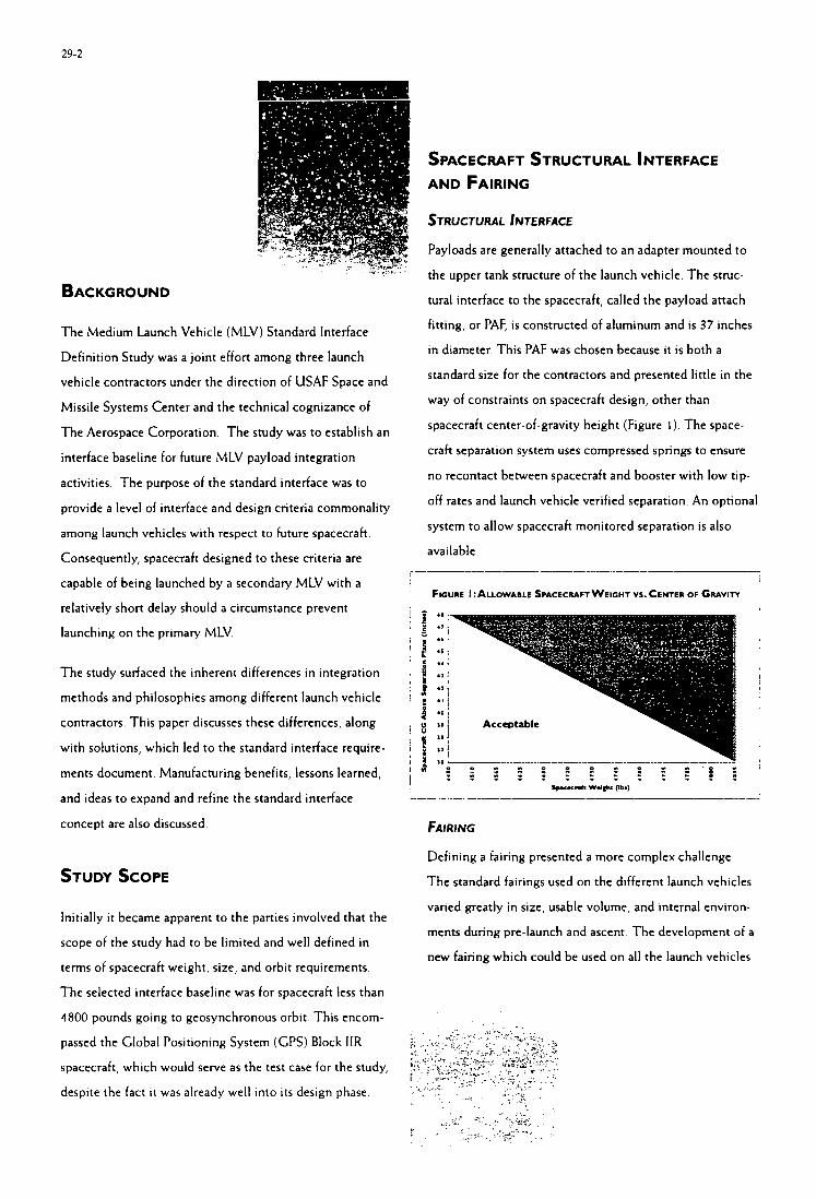
29-2
SPACECRAFT STRUCTURAL INTERFACE AND FAIRING
STRUCTURAL INTERFACE
BACKGROUND
The Medium Launch Vehicle (MLV) Standard Interface
Definition Study was a joint effort among three launch
vehicle contractors under the direction of USAF Space and
Missile Systems Center and the technical cognizance of
The Aerospace Corporation The study was to establish an
interface baseline for future MLV payload integration
activities. The purpose of the standard interface was to
provide a level of interface and design criteria commonality
among launch vehicles with respect to future spacecraft.
Consequently, spacecraft designed to these criteria are
capable of being launched by a secondary MLV with a
relatively short delay should a circumstance prevent
launching on the primary MLV.
The study surfaced the inherent differences in integration
methods and philosophies among different launch vehicle
contractors. This paper discusses these differences, along
with solutions, which led to the standard interface require-
ments document. Manufacturing benefits, lessons learned,
and ideas to expand and refine the standard interface
concept are also discussed
STUDY SCOPE
Initially it became apparent to the parties involved that the
scope of the study had to be limited and well defined in
terms of spacecraft weight, size, and orbit requirements.
The selected interface baseline was for spacecraft less than
4800 pounds going to geosynchronous orbit. This encom-
passed the Global Positioning System (CPS) Block IIR
spacecraft, which would serve as the test case for the study,
despite the fact it was already well into its design phase.
Payloads are generally attached to an adapter mounted to
the upper tank structure of the launch vehicle. The struc-
tural interface to the spacecraft, called the payload attach
fitting, or PAF, is constructed of aluminum and is 37 inches
in diameter. This PAF was chosen because it is both a
standard size for the contractors and presented little in the
way of constraints on spacecraft design, other than
spacecraft center-of-gravity height (Figure I ) . The space-
craft separation system uses compressed springs to ensure
no recontact between spacecraft and booster with low tip-
off rates and launch vehicle verified separation. An optional
system to allow spacecraft monitored separation is also
available.
FIGURE ALLOWABLE SPACECMFT WEIGHT vs. CENTER OF G ~ v i r r
FAIRING
Defining a fairing presented a more complex challenge
The standard fairings used on the different launch vehicles
varied greatly in size, usable volume, and internal environ-
ments during pre-launch and ascent The development of a
new fairing which could be used on all the launch vehicles
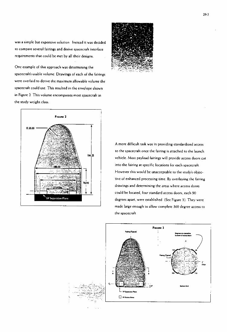
29-3
was a simple but expensive solution Instead it was decided
to compare several fairings and derive spacecraft interface
requirements that could be met by all their designs.
One example of this approach was determining the
spacecraft's usable volume. Drawings of each of the fairings
were overlaid to derive the maximum allowable volume the
spacecraft could use. This resulted in the envelope shown
in Figure 2. This volume encompasses most spacecraft in
the study weight class.
FIGURE 2
A more difficult task was in providing standardized access
to the spacecraft once the fairing is attached to the launch
vehicle. Most payload fairings will provide access doors cut
into the fairing at specific locations for each spacecraft.
However this would be unacceptable to the study's objec-
tive of enhanced processing time. By overlaying the fairing
drawings and determining the areas where access doors
could be located, four standard access doors, each 90
degrees apart, were established. (See Figure 3). They were
made large enough to allow complete 360 degree access to
the spacecraft
29-4
Booster Roductron Upper Stage Producaon Final Integration & Launch
MANUFACTURING /MPLlCATlONS
The standardization of both the structural interface and
fairing previously described would optimize processing
time for launch vehicle manufacturers and consequently the
orbit delivery time for spacecraft. Presently launch vehicle
manufacturers incorporate mission modifications for each
spacecraft customer. Manufacturers have little control over
customer's need dates, and therefore must modify produc-
tion planning, scheduling, and control. In summary, this
discontinuous manufacturing flow negatively impacts:
+ Productioity
+ Producibiliv
+ Quality of Interface Hardware
+ Rmork and Repair
+ Cycle Timcs
+ + Material and Labor Costs
+ Design-to-Production Process
Pari Count 6r Inomtory of Paris
In addition, the following tasks and obstacles could be
potentially eliminated with a standardized interface:
+ Specialized tooling
+ Specialized testing
+ Specialized procedures
+ + Last-minute customer requirements cbanga
Detailed and customized Engineering reviews
I I ! \ \ I \ \ I
\ I \
1 . . . I I - CycleTime I (Note: Upper Stage production times can range from 10%
to 30% of total production time among the different launch
vehicles.)
FUTURE MANUFACTURING CONSIDERATIONS
Presently, both launch vehicle and satellite manufacturers
must perform an initial "fit-check" to ensure the accurate
integration of the launch vehicle upper stage and the new
spacecraft. Structural, mechanical, and electrical connec-
tions are verified in preparation for the launch vehicle and
spacecraft mating on the launch pad. The fit-check process
consumes at least one month of processing time and
associated material, testing, and transportation costs.
Clearly, a standardized interface would greatly reduce the
complexity and potentially the need for fit-checks
To mitigate risk and to maintain the same level of confi-
dence of the fit-check, launch vehicle and spacecraft
manufacturers should consider the following in its replace-
ment:
+ Interface master tooling
+ Computcr models
+ Formal process and procedures IO manufacture to tbc
. .. -.__. i 2: .";. . .. . '. . ..:.'
... ... . . . . . . ., .. t
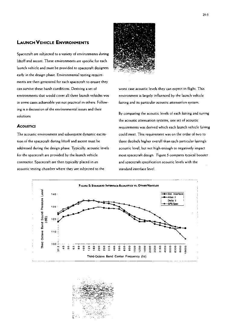
29-5 ~
t LAUNCH VEHICLE ENVIRONMENTS
Spacecraft are subjected to a variety of environments during
liftoff and ascent. These environments are specific for each
launch vehicle and must be provided to spacecraft designers
early in the design phase. Environmental testing require-
ments are then generated for each spacecraft to ensure they
can survive these harsh conditions. Deriving a set of
environments that would cover all three launch vehicles was
in some cases achievable yet not practical in others. Follow-
ing is a discussion of the environmental issues and their
solutions.
ACOUSTICS
The acoustic environment and subsequent dynamic excita-
tion ot the spacecraft during liftoff and ascent must be
addressed during the design phase. Typically, acoustic levels
for the spacecraft are provided by the launch vehicle
worst case acoustic levels they can expect in flight. This
environment is largely influenced by the launch vehicle
fairing and its particular acoustic attenuation system. I
1 By comparing the acoustic levels of each fairing and tuning
the acoustic attenuation systems, one set of acoustic
requirements was derived which each launch vehicle fairing
could meet. This requirement was on the order of two to
three decibels higher overall than each particular fairing's
acoustic level, but not high enough to negatively impact
most spacecraft design. Figure 5 compares typical booster
contractor. Spacecraft are then typically placed in an
acoustic testing chamber where they are subjected to the
and spacecraft specification acoustic levels with the
standard interface level.
__ _ _ -~ F i c u n E 5: STANDARD INTERFACE ACOUSTICS VI . OTHERVEHICLES -
0) I -1 0) 1 4 0 -; j+Std. lnterfecei I
m
. i i
. ___- , - - . , i z 100-
r m o o m o o m o o o m o o o o o o o o o o o o o o o c ; 0 m w m O N W 0 ~ - 0 0 m 0 0 m 0 0 0 ~ 0 0 0 0 0 r - - N N O t m w m O N W O m - O O m O O
- - - N N m P U 2 W m O 0 - Third-Octave Band Center Frequency (hz)
29-6
THERMAL
Another environmental factor which proved to be more
difficult in defining a baseline was the free molecular
heating (FMH) which occurs during ascent. These rates are
highly dependent on the specific trajectory flown. Cuide-
lines for FMH were established, but it was decided that the
variability of these rates vs. trajectory was too large to
standardize. Trajectory simulations to address this are
discussed later.
SPACECRAFT DESIGN LOADS
Spacecraft contractors must design their structures to
withstand dynamic accelerations imposed on them during
flight These accelerations are maximized at flight events
such as liftoff, transonic flight, launch vehicle engine
shutdowns, fairing separation, and spacecraft separation. In
a typical spacecraft integration, design load factors (DLF)
are supplied by the launch vehicle contractor. The DLF are
intended for application at the spacecraft’s center of gravity
to evaluate the primary structure. Once a preliminary
spacecraft dynamic model is developed, a preliminary
coupled loads analysis (PCLA) is done which combines the
dynamic models of both the spacecraft and launch vehicle.
This supplies the spacecraft designers with accelerations,
deflections, and margins of safety, which are used to
evaluate the current design. Once the spacecraft design is
finalized, a final coupled loads analysis (FCLA) is per-
formed to ensure that design changes from the PCLA are
acceptable.
Deriving load factors for this study was difficult in that an
envelope of the three different launch vehicles would be
overly conservative, but load factors which were too low
would could cause the spacecraft to be undersigned structur-
ally Finally a set of DLFs were derived which was believed
to encompass the more severe events for each launch
vehicle, as shown in Table I
TABLE I. SPACECRAFT LIMIT LOAD FACTORS(G’S)
Auill w Max Lateral t I 0, -2.5 +I- 3.0
Max Axial t3.0, -6.9 +I- 1.0
Max Combined +3.0. -6.0 +I- 2 . 5
Note: (+) Tension ( - ) Compression
Two methods were considered for performing the CLAs
One was to try and synthesize dynamic models and forcing
functions which would encompass all three launch vehicles’
characteristics. However, this method soon proved to be
quite formidable due to the differences in launch vehicle
structural characteristics and forcing functions and their
effect on spacecraft loads. Instead it was decided to run a
separate CLA for each launch vehicle/spacecrah. While this
method goes against the standard interfacc concept, it is
cost-effective while meeting the objective of a quick call-up.
The concept of developing a standard launch vehicle model
and forcing functions is intriguing, and should be the subject
of further study.
TRAjECTORY ANALYSES
A large part of mission integration is in trying to optimize
the trajectory flown by the launch vehicle. Parameters such
as sun angles, eclipse periods, thermal maneuvers, ground
station coverage, and launch windows are derived from this
29-7
process. It proved t o be much too complex t o derive a
standardized trajectory which would cover all launch
vehicles. Similar to the coupled loads analyses, it was
determined to be more effective to provide three separate
trajectory analyses to the spacecraft mission planners.
Trajectory optimization could be performed after a specific
launch vehicle was established.
GROUND SYSTEMS AND SPACECRAFT HANDLING
When a spacecraft is on the ground, it requires a number of
services which are typically supplied by the launch vehicle
contractor. Table 2 lists some of these services. Military and
scientific spacecraft typically have greater service require-
ments than less complex commercial spacecraft.
The interfaces at the launch sites were some of the most
difficult to standardize. How launch vehicles were pro-
cessed at their launch sites varied greatly. For instance, one
encapsulated the payload inside the fairing before transport
and erection, one encapsulated after launch vehicle
attachment, and one preferred that the spacecraft provide
their own transportation to the launch pad. Despite these
differences certain ground system and handling interfaces
were established which influence spacecraft design.
TABLE 2: LAUNCH SYSTEM-SUPPLIED PAYLOAD SERVICES
Analyses & Documentation 0 Accident risk assessmcnt
0 Fligbt sajety data package
o Launcb operations plan
0 Mission spccijcation
O Orbital requirements document
o Preliminary mission analysis
Command, Control, and Communications
Electrical Power
Environmental Control . . . . . . . .
Air conditioning
Cleanliness
Special purges
Factory t a t integration
Fairing access
Fligbt tcnnination system
Hazardous omting
Payload integration jacilitics
Launcb site scbeduling
Ligbtning protection
Ordnance installation
Payload acciss
Payload console in Launcb Control Ctr
Payload processing jacilities
Payload test support
Pneumatic & Fluids + Liquid andgaseous Nitrogen
+ Gaseous Helium
Propellant Servicing + Spin balancing
These interfaces were divided into two categories: space-
craft-provided transport, and launch vehicle-provided
transport. Figure 6 illustrates this concept. Physical,
electrical, and environmental interfaces, including contami-
nation protection, are provided for the launch vehicle-
provided encapsulated transport, Additionally, safety
monitoring and spacecraft personnel requirements are also
specified.
For the option of spacecraft provided encapsulation and
transport, spacecraft hoisting and mating operational
requirement are provided, as well as post-mate and space-
craft personnel requirements
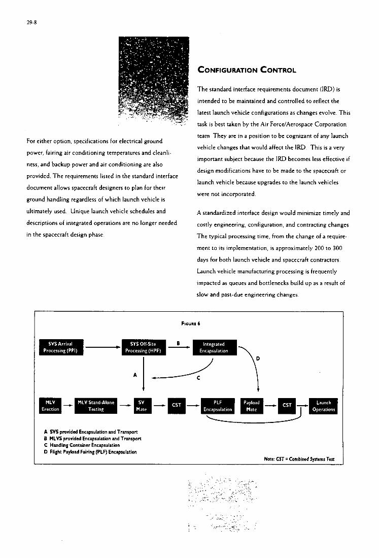
29-8
CONFIGURATION CONTROL
. .,
For either option, specifications for electrical ground
power, fairing air conditioning temperatures and cleanli-
ness, and backup power and air conditioning are also
provided. The requirements listed in the standard interface
document allows spacecraft designers to plan for their
ground handling regardless of which launch vehicle is
ultimately used. Unique launch vehicle schedules and
descriptions of integrated operations are no longer needed
in the spacecraft design phase.
The standard interface requirements document (IRD) is intended to be maintained and controlled to reflect the
latest launch vehicle configurations as changes evolve. This
task is best taken by the Air Force/Aerospace Corporation
team. They are in a position to be cognizant of any launch
vehicle changes that would affect the IRD. This is a very
important subject because the IRD becomes less effective i f
design modifications have to be made to the spacecraft or
launch vehicle because upgrades to the launch vehicles
were not incorporated.
A standardized interface design would minimize timely and
costly engineering, configuration, and contracting changes.
The typical processing time, from the change of a require-
ment to its implementation, is approximately 200 to 300
days for both launch vehicle and spacecraft contractors.
Launch vehicle manufacturing processing is frequently
impacted as queues and bottlenecks build up as a result of
slow and past-due engineering changes
FIGURE 6
B
I I
-
A N S provided Encapsulation and Transport B MLVS provided Encapsulation and Transport C Handling Container Encapsulation D Flight Payload Fairing (PLF) Encapsulation
Note: CST= Combined Systems Test
29-9 I
tbe Air Force to establish an interface baselineforfuture
Payloads. Tbis facilitates multi-launch oebicle usage for
satellites designed to tbese parameters. Botb defense and
commercial satellite customers can realize time and cost
savings as a result ofa standardized interface. Access to
space is a motioatingforce behind tbis effort.
Tbe study concluded that individual analysesfor
dynamic loads and trajectories was warranted due to the
large differences between launcb oebicles in tbese areas.
Requirements for structural interfaces, launcb oebicle
enoironments, and ground systemhpacecraft handling were
deoeloped wbicb are common to all three launcb oebicle
contractors. Clearly tbere are numerous manufacturing
benefits to consider and assess in order to optimize efficiency
as well as risk Future studies should be undertaken to
broaden tbe scope of the standard interface to include otber
orbits and payload weigbts. Additionally, tbe concept of a
standardized launcb oebicle dynamic model and forcing
functions sbould be inuestigated.
t

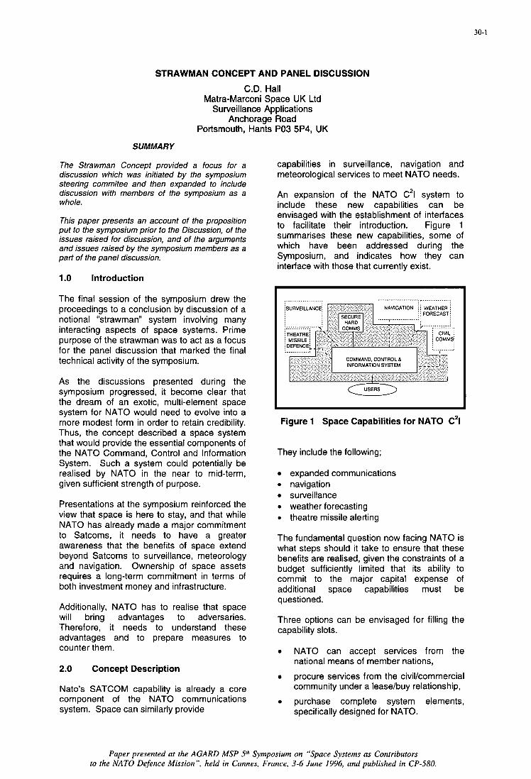
STRAWMAN CONCEPT AND PANEL DISCUSSION
C.D. Hall Matra-Marconi Space UK Ltd
Surveillance Applications Anchorage Road
Portsmouth, Hants PO3 5P4, UK
SUMMARY
The Strawman Concept provided a focus for a discussion which was initiated by the symposium steering commitee and then expanded to include discussion with members of the symposium as a whole.
This paper presents an account of the proposition put to the symposium prior to the Discussion, of the issues raised for discussion, and of the arguments and issues raised by the symposium members as a part of the panel discussion.
1 .O Introduction
The final session of the symposium drew the proceedings to a conclusion by discussion of a notional “strawman” system involving many interacting aspects of space systems. Prime purpose of the strawman was to act as a focus for the panel discussion that marked the final technical activity of the symposium.
As the discussions presented during the symposium progressed, it become clear that the dream of an exotic, multi-element space system for NATO would need to evolve into a more modest form in order to retain credibility. Thus, the concept described a space system that would provide the essential components of the NATO Command, Control and Information System. Such a system could potentially be realised by NATO in the near to mid-term, given sufficient strength of purpose.
Presentations at the symposium reinforced the view that space is here to stay, and that while NATO has already made a major commitment to Satcoms, it needs to have a greater awareness that the benefits of space extend beyond Satcoms to surveillance, meteorology and navigation. Ownership of space assets requires a long-term commitment in terms of both investment money and infrastructure.
Additionally, NATO has to realise that space will bring advantages to adversaries. Therefore, it needs to understand these advantages and to prepare measures to counter them.
2.0 Concept Description
Nato’s SATCOM capability is already a core component of the NATO communications system. Space can similarly provide
capabilities in surveillance, navigation and meteorological services to meet NATO needs.
An expansion of the NATO C21 system to include these new capabilities can be envisaged with the establishment of interfaces to facilitate their introduction. Figure 1 summarises these new capabilities, some of which have been addressed during the Symposium, and indicates how they can interface with those that currently exist.
Figure 1 Space Capabilities for NATO C21
They include the following;
expanded communications 0 navigation 0 surveillance 0 weather forecasting 0 theatre missile alerting
The fundamental question now facing NATO is what steps should it take to ensure that these benefits are realised, given the constraints of a budget sufficiently limited that its ability to commit to the major capital expense of additional space capabilities must be questioned.
Three options can be envisaged for filling the capability slots.
NATO can accept services from the national means of member nations,
procure services from the civilkommercial community under a lease/buy relationship,
purchase complete system elements, specifically designed for NATO.
30-1
Paper presented at the AGARD MSP Sth Symposium on “Space Systems as Contributors to the NATO Defence Mission”, held in Cannes, France, 3-6 June 1996, and published in CP-S80.
30-2
Decisions of this type would certainly be significant policy issues that would need to be decided by NATO and may also need to be agreed by the member nations.
3 issues Raised
Each of these options for space service raise a number of issues that need to be considered in the context of service provision to NATO. These issues were outlined to the symposium in two categories, issues that essentially impact on NATO policy, and issues that impact on particular capabilities from which NATO might benefit.
3.1 issues Impacting NATO Policy
The three issues addressed in this domain ' cover the potential procurement options for filling the technical capability slots identified in the early section.
(a) The National Means Option
National Means refers to the provision of service from a nationally owned space capability. Such capabilities are usually of a sensitive nature, and the provision of service from them may well be associated with caveats, nation-to-nation agreements rather than intra-NATO release, and the possibility of a veto in particular circumstances. In making a decision to accept such service provision on a regular basis, NATO would need to agree with the contributor nations, the associated mechanisms and modalities.
This issue met with general agreement but was qualified by the response that such a procedure would need to be supported by nation to nation understandings and agreements.
(b) The Lease/Buy Option
Examples of the commercial businesses from which NATO could lease or buy service include Inmarsat, Radarsat and Spot Image - and there are more. In making a decision to follow such a course, NATO needs to consider at least these issues;
0 the priority access which it requires to such systems demands up-front action to establish participation in the Programmes
0 it will need to consider the cost- effectiveness of guaranteed use/access to communications satellites
0 it will need to understand whether the operations charter of such organisations allow their use for military activities in times of crisis and conflict
0 it will need to provide an infrastructure to manage and exploit the resources it plans to use
Both the panel and the symposium felt that this area provided a positive opportunity for NATO to gain useful capabilities, affordably. However, concern was expressed that the same assets can provide corresponding benefits to adversaries and that techniques need to be explored to assess the benefit to potential adversaries, and where necessary, to mitigate that benefit.
Typical areas where such analysis is needed include the GPS navigation service and communications services from international agencies such as INMARSAT. It was felt that international agencies presented a greater potential threat than (NATO) national agencies. Concern was anticipated from some non- NATO nations (and indeed from within member nations) if any interference were made to the service which they enjoy.
Nevertheless, real benefits to NATO were acknowledged and the ease of interoperability across national boundaries that such international systems provide, was seen as a particular benefit. This benefit was also seen as an example from which future military system designers may learn.
(c) The Direct Purchase Option
The direct purchase of complete space systems usually comes at an appreciable price. If NATO were to follow this course, it would have to undertake careful preparations.
0 requirements placed on the systems would need to be explicit and agreed
0 costs and funding arrangements would need to be defined
0 infrastructures to manage and exploit the systems would have to be provided
The potential for NATO to make direct purchases of major system elements was acknowledged as being limited. However, earlier discussions during consideration of the lease/buy option were recalled to emphasise
30-3
the need for a dedicated, hardened communications capability for NATO and the great value of such a system being wholly owned and controlled by NATO.
3.2 Issues Impacting Capabilities
The four capabilities addressed in this domain included communications, surveillance, navigation, and meteorology.
(a) Communications
A number of issues, some inter-related and some distinct, were identified for discussion in this area.
what will be the impact of direct broadcast television and reporting services in the information wars that are regularly associated with conflicts and expected by the public?
how will NATO manage and control these services in such circumstances?
what will be the impact of the messaging capabilities that are expected to be globally/universally available ?
what will be the impact of video conferencing to both civil and military users ?
how valuable will these services be to an adversary ?
Then apart from these issues that derive essentially from the civikommercial domain, the issues relating to frequency band i.e. UHF, SHF and EHF are still to be resolved in the military domain .
(b) Surveillance
Issues identified in the surveillance domain include the following;
what is the NATO’s requirement on surveillance information? Is it a requirement for information products already extracted from raw imagery by Information Providers, or is it for raw imagery to be operated on by NATO staffs?
if the latter, NATO will need to provide an infrastructure to manage and exploit the extraction of information from the raw imagery
0 in times of tension, will NATO be able to compete successfully with existing image providers. Competition can be expected from the international media and from adversaries?
(c) Navigation
There was agreement that the issue of navigation was already well covered by GPS and agreement that such data is vital for battle management. However, it was appreciated that the civil world has now become so enormously reliant on GPS that removal of the service from the civil community during military conflict is unthinkable.
Therefore the issues posed to the navigation service providers are
is denial of the service a credible option, given the proliferation of its use by civil services?
how can its use be denied to an adversary while still maintaining a service to the civil community?
although (it is understood that) the USA has promised to pay for GPS “for some time”, NATO need to consider the implications of who will be paying for maintenance of the service into the longer term future
(d) Meteorological Services
Weather data is vital for battle management and during crises. However, although the military user has access to dedicated military meteorological satellites, the civil community has access to similar assets.
Access to the military meteorological satellites can be denied to an adversary by data down- link encryption. However, the issue that remain are as follows;
will it be possible similarly to deny access to metsats in GEO and/or LEO i.e. does the hardware provide a downlink encryption capability?
will the charters of operation allow such denial?
0 is the mere availability of raw Met-sat data actually so important?
30-4
4.0 ISSUES RAISED IN DISCUSSION
In addition to the invited topics addressed in the panel discussion, a number of additional issues were raised from the floor. These included the following;
Training and Exercising
There was general agreement that space systems can provide an important capability to NATO and to adversaries. Therefore, there is a need to include such systems in training exercises so that NATO forces learn how to exploit them, and how to counter the advantage that they may bring to an adversary.
This issue is encapsulated in the philosophy, ‘train the way we fight, fight the way we train’. A step in the right direction to achieve this would be the setting up of a NATO Space Warfare Centre
lnteroperability
It was noted that a significant step towards interoperability would be the design of systems providing products to a standard information transfer format. System designers were reminded of the many NATO standards (Stanags) that exist and commended to make use of them to achieve the desired goal.
This has worked in the communications area, but it was noted that although the WEU has established an image interpretation system (Torrejon), NATO does not have such a system. It was reported that the Agard Special Study, AAS-42, recommended that NATO should start by buying in imagery and perhaps first level information products from the commercial sector. However, higher level products should be generated by NATO staff.
It was suggested that it may be possible to use the NATO Satcoms experience as training to how to integrate other space data sources.
Asset Denial to an Adversary
Denial of assets was agreed to be a difficult task. For example, in the meteorology area it was pointed out that a growing number of nations are developing and using their own satellites and that NATO has no control over such data sources.
The difficulty of restricting the navigation service provided by GPS was re-affirmed. Additionally, a further difficulty was posed in anticipation of the GPS service being handed over to a multi-national organisation within the next 15 years.
Purchasing and Asset Acquisition
Further discussion of this topic raised a linkage that interoperability would be facilitated within a NATO purchased system. However, it was pointed out that NATO should only purchase where absolutely necessary, and that system architectures would need to be studied before NATO makes such a decision.
5.0 CONCLUSIONS
The panel discussion session concluded that the importance of space to NATO is so great that NATO be recommended to establish a policy for space, and a programme office from which to co-ordinate that policy.
Generally, discussion and comment both from the panel and from the floor, raised issues and questions that such a policy would need to address. Responses to those questions would be ideally co-ordinated from such an office.
In summary the principal issues identified were as follows;
NATO needs to maintain its hardened communications core element as an ultimate guarantee of communications and control during crises.
civikommercial assets can potentially provide a useful capability but NATO needs to set appropriate arrangements in place to acquire those services
NATO needs to study carefully the issues and impacts raised by availability of commercial services to an adversary, together with techniques for their denial
training exercises for NATO forces need to include all space systems intended for use in conflict
Finally, space is here to stay and NATO needs to establish a policy for space.
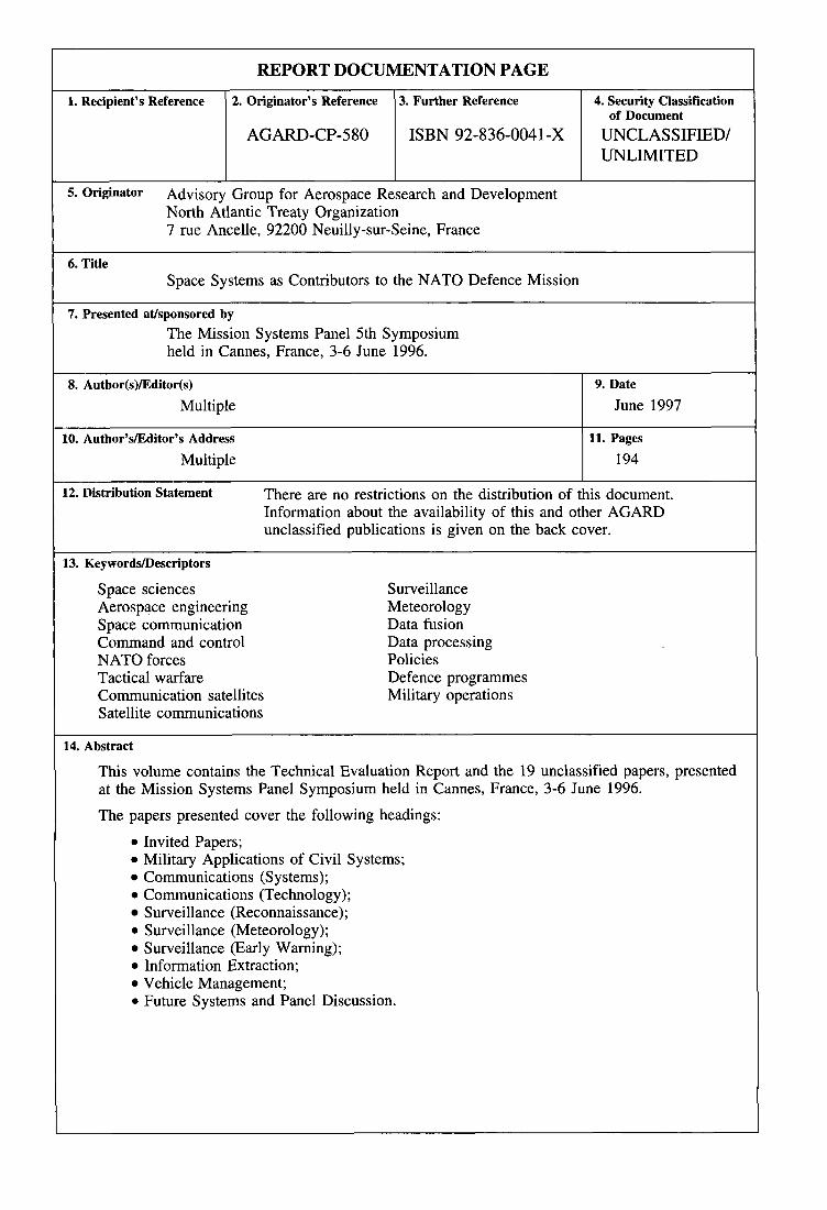
REPORT DOCUMENTATION PAGE
1. Recipient’s Reference 2. Originator’s Reference 3. Further Reference 4. Security Classification of Document
UNLIMITED AGARD-CP-580 ISBN 92-836-0041-X UNCLASSlFIED/
5- Originator Advisory Group for Aerospace Research and Development North Atlantic Treaty Organization 7 rue Ancelle, 92200 Neuilly-sur-Seine, France
8. Author(s)/Editor(s)
Multiple
6. Title Space Systems as Contributors to the NATO Defence Mission
9. Date
June 1997
10. Author’slEditor’s Address
Multiple 11. Pages I 194
12. Distribution Statement There are no restrictions on the distribution of this document. Information about the availability of this and other AGARD unclassified publications is given on the back cover.
13. KeyworddDescriptors
Space sciences Aerospace engineering Space communication Command and control NATO forces Tactical warfare Communication satellites Satellite communications
Surveillance Meteorology Data fusion Data processing Policies Defence programmes Military operations
14. Abstract
This volume contains the Technical Evaluation Report and the 19 unclassified papers, presented at the Mission Systems Panel Symposium held in Cannes, France, 3-6 June 1996.
The papers presented cover the following headings:
0 Invited Papers; 0 Military Applications of Civil Systems;
Communications (S y s terns) ; 0 Communications (Technology);
Surveillance (Reconnaissance); 0 Surveillance (Meteorology);
Surveillance (Early Warning); Information Extraction; Vehicle Management;
0 Future Systems and Panel Discussion.

1


I
NATO +- OTAN
7 RUE ANCELLE 92200 NEUILLY-SUR-SEINE DIFFUSION DES PUBLICATIONS
FRANCE AGARD NON CL-
TMwpie 0(1)55.61.22.99 TBlex 610 176 A~enm dock de plblicptions n'a wdstc A AGARD. A pSnir de 1993. AGARD d6timdra un Sock des publldom associecs 8ux cyclea d e d ~ e t o o l w ~ a i t l s i q u e l e a AG des ~roupcs de mA, organises et pub!i& Apsrtirde 1993 inch Los demandCS de n-nseigomxmts doivent h A G W pruleme ou pp fax AI'adressc indiquk n-dessus. Veulucznr pas fblcphoncr. La ddfuaion iniliak de h t e a la publications de I'AGARD eat &eau& aup& dca pya mmbm de I'OTAN par
w%%ntrea (A I'exceptiOn dsa Etats-Ulds). Si vow souhaitcl recevoir h k s les pubM=A&. w aimplaumt collea qm cowamt cgtains Panels, vow a dcmnodaP &re inch sor la liste d'envoi de I'm de cm ccntns. Lcs pubhcaiiom de I'AGARD mot m vente suprz~ des agcnces &%n ci-deasous. 8ou8 fwne de pllotoeapie w de &ti&.
'ea et lea
I'm ' . des aatns de distribution nalionaux indiquk cideasous. Dea exemplaircs supp ' v a t @e& &re obtcnus
CENTRES DE DIFFUSION NATIONAUX ALLEMAGNE ISLANDE
BELGI UE Reykjavik
FachinformPrionszenrm Karlsmbe Dincta of Aviation D76344 E ~ t e h - ~ l d s h a f e n 2 do Flugrad
&noateur AGARD-VSL lTm W-major de la Force adricnne QulntiarmeElisabcth Rue d'Evon. 1140 Bmellea
A d c a Militan
3 Pomezia (Roma) LUXEMBOURG
Voir B e l g i p
Ufficio del Debgrto Nazionale dl ACIAKO rtoRaticadiMarc
Ryvangs All6 1 PI). Box 2715 DIG2100 Copcnhagcn 0
NORVBOE Defmcz Research Establishment
EYGotebt P.O. Box 25
NORVBOE Defmcz Research Establishment
EYGotebt P.O. Box 25 N - M KJeUex
Netherlands Dcle~alion to AGARD PAYS-BAS
National A m s - Laboratmy NLR P.O. Box 9 O S r 1006 BM Amsterdam
Estado Maior da F o ~ a A b SDFA - cmtro de Dommah@
ESPAGNE INTA (AGARD P ~ b l i ~ a h ~ ~ ) Camtua de Tm~cj6n a Ajalvk Pk.4 28850 Tomj6n de Ardoz - Madrid
NASA Ccntsr for AcmSpace Information (CASI) Linthicum ngnts. MD 2109a2934 2700 Amadora
ROYAUMEUNI O.N.E.R.A. (Dhction) 29, Avenue de la Division Lcclere 92322 chetillon Ccdex
Hcllcnic Air Force Air war con Scientific aodi&cal Librmy Dekclia Air Fora Bape Dekelia, Atkm lyjA 1010
PORTUGAL ETArruNIs
Alflagide mm%-Road
Defence Rcgearch Infomlation centre Kentigem House 65 Brown Strcet Glasgow 02 SEX
MilU Santnma Ba$kad$~ WSB) ARGE Dainsi Bqkanligi WSB) 06650 Baka~Wa~Ankara
FRANCS
mQm GRECE
Le centre de distrobrtioll IIMIOMI des Etats-UnIa m detient PAS de daelol dg pnbUcatlmm de I'AGARD. D 6 v e n e dmLandes de photocnpiea doivent &e fonnul& dinaunm t aupzS du NASA ccnta for Aaospacc Informatim (CAS9 A l'adrcssc ci&asws. Twte notifi&on de changmcnt d'adnsse doit &e fait 6galement aup& de CASI.
AGENCES DE VENTE NASA Center for A d p a c e Information Thc British Library
Documcot Supply Division Boston Spa, Wetberby West Yorkshire U23 7BQ
(CASI) 800 Elkridge Landing Road Linthicum Heigbtn. MD 2109a2934 EW-IJnis Royaume-uni
Lss demandes de micmfichas ou de photowpies de doarmmte AGARD (y wmpm ICs dcmaadss faitea du CASI) doivmt compoPtcr la denominntion AGARD, ainsi le n& dc scric d'AGARD (par exmple AGARD-AG%. Dca informatiom ~nalogucs. telles que le titre et la dntc de &on aont souhaitables. veuilla noter qn'n y a lieu specifier A G A R D - R - ~ et AGARD-AR-nnn lm de la c o d e des rapPoas AGARD et des rapPoas wnsultalXa AGARD m p t i v e n m t . Dca r6f&ence bibliagraphiqncs comp&tea aiapi que des r&nn~& de8 publicstions AGARD figurent drms Lss joumaux suivants:
Scimtific and Tecbmcal Aerospace Reports (STAR) publit par la NASA Scientific and Technicd Information Division
Government Reporta Annoonccmen!a aod Indw (GRA&I) puE6,lb" National Technical Information S-
NASA Langley Research Center Hampton. Virginia 23681-oOOl Etats-Ulds
$ i 22161 Etats-Unis (accessible cgalement en mode interactif donneeS bibliograpbiqnes en du NTIS, et sur CD-RObQ. . la base de
(membw de la Corporation St-Joseph) 45, bod. Sacrl-Ca?ur, HUN (Qdbec), C d KlA OS7
I ..I c
P- I
I I l l
Related Documents


![SERBIA – NATO DEFENCE COOPERATIONweb].pdf · 5 related to defence reform in Serbia and the country’s relations with NATO. BCSP Execu-tive Director Sonja Stojanović-Gajić provided](https://static.cupdf.com/doc/110x72/5e207eb4e7416a0c2938a715/serbia-a-nato-defence-webpdf-5-related-to-defence-reform-in-serbia-and-the.jpg)