ENVIRONMENTAL RESOURCES MANAGEMENT CAPRICORN GREENLAND EXPLORATION 1 5-1 5 PROJECT DESCRIPTION 5.1 PROJECT OVERVIEW Capricorn Greenland Exploration 1 (“Capricorn”), a subsidiary of Cairn Energy (“Cairn”), is planning to undertake an exploration drilling programme in the Sigguk exclusive licence 2008/10 (Sigguk Block), Disko West Area offshore West Greenland in the summer of 2010 (see Figure 5.1). This follows a 2D Seismic programme undertaken in 2008 and further geophysical survey and environmental monitoring programmes completed in 2010. The Disko West Area includes the north-eastern part of the Davis Strait and the south-eastern part of Baffin Bay, with Disko Island as the most prominent landscape on the Greenland coast. This area is a part of the Arctic Region, known for harsh weather conditions and drift ice. The Sigguk Block is located over 100 km from the closest point of the west Greenland coast in water depths ranging from approximately 250 to 1,800 m. The block, in which Capricorn holds a 77.5% working interest, comprises the northern part of Capricorn’s Disko West License, which also includes a 77.5% working interest in the Eqqua Block (Block 3) located immediately to the south of Sigguk. Cairn Energy, through its exploration subsidiary Capricorn, has secured a working interest in a total of eight exploration licences off the south and west coasts of Greenland, although the current drilling programme and the remit of this assessment is concerned solely with the planned exploration programme in Block 1, Sigguk. The drilling programme is planned to take place between June and September 2010, with a two month contingency period built into the schedule for relief well drilling if required. If the operations proceed according to plan, the first drill unit will mobilise to Greenlandic waters in June and will demobilise following completion of all operations. The drilling programme itself will employ a range of cutting-edge technology and operating standards to meet the challenges of drilling in the offshore arctic environment. Two mobile offshore drill units (MODUs) will be employed in order to provide a high degree of operational and safety contingency. A range of vessels will be employed to provide support and emergency cover for the operations, including supply boats, support vessels and ice breakers. Ongoing consultation with the public and stakeholders will also be carried out to ensure the local population remains fully informed and has the opportunity to engage during the planning process.

Welcome message from author
This document is posted to help you gain knowledge. Please leave a comment to let me know what you think about it! Share it to your friends and learn new things together.
Transcript

ENVIRONMENTAL RESOURCES MANAGEMENT CAPRICORN GREENLAND EXPLORATION 1
5-1
5 PROJECT DESCRIPTION
5.1 PROJECT OVERVIEW
Capricorn Greenland Exploration 1 (“Capricorn”), a subsidiary of Cairn Energy (“Cairn”), is planning to undertake an exploration drilling programme in the Sigguk exclusive licence 2008/10 (Sigguk Block), Disko West Area offshore West Greenland in the summer of 2010 (see Figure 5.1). This follows a 2D Seismic programme undertaken in 2008 and further geophysical survey and environmental monitoring programmes completed in 2010. The Disko West Area includes the north-eastern part of the Davis Strait and the south-eastern part of Baffin Bay, with Disko Island as the most prominent landscape on the Greenland coast. This area is a part of the Arctic Region, known for harsh weather conditions and drift ice. The Sigguk Block is located over 100 km from the closest point of the west Greenland coast in water depths ranging from approximately 250 to 1,800 m. The block, in which Capricorn holds a 77.5% working interest, comprises the northern part of Capricorn’s Disko West License, which also includes a 77.5% working interest in the Eqqua Block (Block 3) located immediately to the south of Sigguk. Cairn Energy, through its exploration subsidiary Capricorn, has secured a working interest in a total of eight exploration licences off the south and west coasts of Greenland, although the current drilling programme and the remit of this assessment is concerned solely with the planned exploration programme in Block 1, Sigguk. The drilling programme is planned to take place between June and September 2010, with a two month contingency period built into the schedule for relief well drilling if required. If the operations proceed according to plan, the first drill unit will mobilise to Greenlandic waters in June and will demobilise following completion of all operations. The drilling programme itself will employ a range of cutting-edge technology and operating standards to meet the challenges of drilling in the offshore arctic environment. Two mobile offshore drill units (MODUs) will be employed in order to provide a high degree of operational and safety contingency. A range of vessels will be employed to provide support and emergency cover for the operations, including supply boats, support vessels and ice breakers. Ongoing consultation with the public and stakeholders will also be carried out to ensure the local population remains fully informed and has the opportunity to engage during the planning process.

Figure 5.1 Project Location
Hydrocarbon Licence Blocks Offshore Greenland (BMP, 2010)
Block 1 “Sigguk” shown shaded in blue (BMP, 2010)
ENVIRONMENTAL RESOURCES MANAGEMENT CAPRICORN GREENLAND EXPLORATION 1
5-2

ENVIRONMENTAL RESOURCES MANAGEMENT CAPRICORN GREENLAND EXPLORATION 1
5-3
5.2 PROPOSED WELL LOCATIONS
The programme will involve the drilling of four wells in the Sigguk Block in the Disko West Area. The locations for the first two wells have been confirmed as Alpha and T8. The second two wells, which are the subject of this Impact Assessment, will be selected from four potential locations; T3, T4, T16 and T23.
Table 5.1 Proposed Well Site Options
Coordinates No. Location Name X Y
Estimated Water Depth (m)
1 Alpha (1st stage) 444436 7801685 -319 (+/-2m) 3 T8 (1st stage) 404788 7801397 -490 (+/-2m) 2 T3 (2nd stage – option) 418861 7880420 -380 (+/-10m) 4 T4 (2nd stage – option) 395253 7894307 -485 (+/-10m) 5 T16 (2nd stage – option) 422105 7837428 -631 (+/-10m) 6 T23 (2nd stage – option) 423080 7809145 -431.7 (+/-2m)
This assessment includes details related to the entire drilling programme as it is important that the impacts associated with drilling individual wells are not assessed in isolation, but considered as part of the wider drilling project. Detailed environmental survey data is included for the T3 and T4 potential drilling locations. Environmental survey results for T16 and T23 are being finalised and will be added to the EIA report as soon as they become available.

IlulissatQerqertarsuaq
T4
T8 T23
T16
T3C3
Alpha
CLIENT: SIZE: TITLE:
DATE: 08/06/2010
DRAWN: CJ
CHECKED: RB
APPROVED: JP
PROJECT: 0108885
As scale barDRAWING: REV:
KEY: Capricorn Greenland Exploration-1 A4 Figure 5.2
Location of Proposed Well Sites Options within the Sigguk Block
5.2_WellSiteOptions.mxd 0
Licence AreaWell Location
SOURCE: Capricorn Greenland Exploration-1PROJECTION: WGS 1984 UTM Zone 21N
File:
0108
885G
reenla
ndW
estG
IS_C
J_JP
\Map
s\Well
3 an
d 4\5.
2_We
llSite
Optio
ns.m
xd
ERMEaton HouseWallbrook CourtNorth Hinksey LaneOxford, OX2 0QSTelephone: 01865 384800Facsimile: 01865 204982.0 50
Kilometres© ERM This print is confidential and is supplied on the understanding that it will be used only as a record to identify or inspect parts, concepts or designs and that it is not disclosed to other persons or to be used for construction purposes without permission.

ENVIRONMENTAL RESOURCES MANAGEMENT CAPRICORN GREENLAND EXPLORATION 1
5-5
5.3 PROPOSED PROJECT SCHEDULE
The proposed drilling programme will utilise a two rig strategy, whereby two separate MODUs are used to drill the proposed wells during the overall project window. The first drill unit will mobilise and begin operations ahead of the second unit, with both units expected to be operating in parallel within the project area for around three months. The first MODU on location in Greenland will be a semi-submersible drill rig (the “Stena Don”), which will be mobilised to the region to commence drilling in late June/early July 2010. The second MODU will be the drill ship (the “Stena Forth”), which is planned to mobilise to the region to commence drilling operations in July 2010. Drilling is anticipated to be completed by end of September 2010, with a 37 day relief well window as a contingency. A broad outline of the proposed schedule is presented in Figure 5.3 below.
Figure 5.3 Outline Drilling Schedule
2010 May June July August Sept Oct Nov
Mobilisation
Drilling (4 wells)
Relief Well
5.4 PROPOSED DRILL UNITS
5.4.1 Drillship (Stena Forth)
The drillship to be utilised is the Stena Forth which is designed to work in open water broken ice and is illustrated in Figure 5.4 below. The drillship is a maritime vessel which includes two drilling well centres and the latest station-keeping equipment. The vessel is capable of operating in deep water. The Stena Forth mobilised from its previous operating location in the Gulf of Mexico to Greenlandic waters.

Figure 5.4 Stena Forth Drillship
Photo courtesy of Stena
The Stena Forth is expected to drill two wells to completion and will demobilise at the end of September 2010, depending on results of the wells drilled Selected technical specifications for the Stena Forth are presented in Table 5.2 below.
Table 5.2 Stena Forth Specifications
Rig type Dynamically Positioned Drillship Unit flag Bermudan Year of construction 2008 Unit design/shape Double Hull Drillship Type of Positioning system (anchor/dp/combined) Dynamically Positioned Vessel Class Weight (light ship) 38,948 mt Fuel consumption, drilling 40 t/day Accommodation for maximum no. of personnel persons
180 (10 single & 85 double berth cabins)
Length overall 228 m
ENVIRONMENTAL RESOURCES MANAGEMENT CAPRICORN GREENLAND EXPLORATION 1
5-6

ENVIRONMENTAL RESOURCES MANAGEMENT CAPRICORN GREENLAND EXPLORATION 1
5-7
Breadth overall 42 m Storage Capacities Fuel 6,500 m3 Drilling water 5,000 m3 Potable water 2,000 m3 Mud processing tank 90 m3 Active liquid mud 746 m3 Reserve liquid mud 2,400 m3 Bulk bentonite/barite 420 m3 Bulk cement 420 m3 Sack storage 7,000 sacks Propulsion/Thrusters Thrusters\Type (azimuth/in line) Azimuth thrusters fixed, AQM UUC 455
L-Drive (Rolls Royce Aquamaster) Quantity No. 6 Thruster Power 5,500 kW Operational Capabilities Max. designed water depth capability 3,650 m Outfitted max/min water depth capability 2,285 m Drilling depth capability 10,700 m Transit speed towed (Estimated) n/a Transit speed self propelled (Estimated) 12 knots Mooring System 2 anchor winches Helicopter Landing Deck Location Forward end above bow Dimensions 25.9 m x 25.9 m Load capacity 12.8 mt Heli-refueling system type Yes/Helifuel A.S Fuel storage capacity 600 US gallons Power Supply Systems Diesel Engine Plant 6 Make/Type Wartsilla/16V32 Maximum continuous power 7,430 kW AC-Generator 6 Continuous power (Each) 7,430 kW Motors Thrusters Motors 6 Drilling Motors 16 Water Distillation 3 Capacity 30/90 m3 /day Boilers 2 Capacity 12,000 kg/h Living Quarters Total persons accommodated No. 180 Quantity of single bed rooms No. 10 Quantity of two bed rooms No. 85 Sewage Treatment System type 2 (biological vacuum combined – IMO)
5.4.2 Semi-Submersible (Stena Don)
The second proposed drill unit is the Stena Don, a dynamically-positioned semi-submersible MODU (Mobile Offshore Drilling Unit). The Stena Don mobilised from Invergordon on the north east coast of Scotland before starting its self propelled transit to Greenland.

A semi-submersible is a floating vessel that is supported primarily on large pontoon-like structures submerged below the sea surface. This design has the advantage of minimising loading from waves and wind. Semi-submersibles can operate in a wide range of water depths, including deep water. Some rigs use anchors tethered by strong chains and wire cables, which are computer controlled to maintain station keeping. However the Stena Don uses a dynamic positioning system of thrusters for station keeping rather than using moorings, reducing the need for disturbance of the seabed by the placing of anchors. Detailed specifications are provided in Table 5.3.
Figure 5.5 Stena Don MODU
ENVIRONMENTAL RESOURCES MANAGEMENT CAPRICORN GREENLAND EXPLORATION 1
5-8

ENVIRONMENTAL RESOURCES MANAGEMENT CAPRICORN GREENLAND EXPLORATION 1
5-9
Table 5.3 Stena Don MODU Specifications
Rig type Semisubmersible Unit flag Marshall Island Year of construction 2001 Unit design/shape Twin Pontoon, 6 Columns (4 large, 2 small) CS30 Type of Positioning system (anchor/dp/combined) Dynamic Positioned SDP 21/SDP11, Kongsberg, Class 3 Weight (light ship) 17315 - 17,525t Fuel consumption, drilling t/day 40t/day Accommodation for maximum no. of personnel persons
120 + 8 Offices
Length overall 95.5m Breadth overall 69m incl. helideck Storage Capacities Fuel 2611.2 m3 Drilling water 903.5 m3 Potable water 519.2 m3 Mud processing tank 396.6 m3 Active liquid mud 567.0 m3 Reserve liquid mud 396.0 m3 Bulk bentonite/barite 236.5 m3 (4 tanks) Bulk cement 236.5 m3 (4 tanks) Sack storage 2000 sacks Propulsion/Thrusters Thrusters\Type (azimuth/in line) Kamewa Aqua Master Quantity No. 6 Thruster Power 3.200 kW Operational Capabilities Max. designed water depth capability 500 m Outfitted max/min water depth capability 130 m – 500 m Drilling depth capability 27800 ft Transit speed towed (Estimated) 8 knots Transit speed self propelled (Estimated) 6 knots Mooring system N/A - Emergency Anchors only (2) Helicopter Landing Deck Location Port Fwd Corner Dimensions 22.80 m Load capacity Mt 15t Heli-refueling system type Carter Mod. 64200, delivered by Helifuel A/S Fuel storage capacity M3 2 x transportable tanks 720 USG each Power Supply Systems Diesel Engine Plant 9 Make/Type Wartsila type 16v25-3500kW NOx upgraded Maximum continuous power: 3.5 MW AC-Generator 9 Continuous power (Each) kw: 3500 kw Motors Thrusters Motors 6 x 3300 kW Drilling Motors 2 x 740 kW Water Distillation 2 Capacity M3/day: 3 x 30 m3/day Boilers 2 Capacity MW: 2.7 MW Living Quarters Total persons accommodated No. 120 persons Quantity of single bed rooms No. 2 Quantity of two bed rooms No. 50 Sewage Treatment System type Hamworthy, Vacuum

ENVIRONMENTAL RESOURCES MANAGEMENT CAPRICORN GREENLAND EXPLORATION 1
5-10
Since the Stena Don is a dynamically-positioned rig, there is not a requirement for a dedicated anchor handling vessels to moor the rig. Operations support will be provided by a support vessel depending on the available SAR (Search and Rescue) cover on the voyage route.
5.5 RESERVOIR RESOURCES
In the Disko West area offshore western Greenland, a number of leads at both Cretaceous and Tertiary levels have been identified. Additional 2D seismic data was acquired in 2008 to mature the leads to prospect status. The main prospects are identified in the Cretaceous section in Block 1 (Sigguk). A series of large Tertiary fans of probable Miocene age have been identified, and are located in both Blocks 1 and 3. The interpreted stratigraphy and petroleum systems of the West Greenland Shelf, showing the previous six wells drilled offshore Greenland (in blue) and penetration by onshore wells (in red) is provided in Figure 5.6 below.
5.5.1 Extract of Geological Overview from Geological Survey of Denmark and Greenland (GEUS): www.GEUS.dk.
The margin of West Greenland was formed by extensional opening of the Labrador Sea in late Mesozoic – early Cenozoic time. A complex of linked rift basins stretch from the Labrador Sea to northern Baffin Bay (1). Sedimentary basins, containing up to 8–10 km of sediments, are found primarily between 63°N and 68°N. The oldest sediments in the basins may be of Early Cretaceous age (2), and seismic data indicates at least two rifting events, the first in the Early Cretaceous and the second in the Campanian–Paleocene which was probably associated with the start of sea-floor spreading in the Labrador Sea. Sea-floor spreading in the Labrador Sea was transferred to Baffin Bay to the north along a complex strike-slip fault system, the Ungava Fault Zone. Initial opening of the Labrador Sea was accompanied by voluminous volcanism, probably associated with the impact of the Iceland plume. The largest area of volcanic rocks is found north of 68°N and it extends onshore into the Nuussuaq Basin. Other areas of volcanism are found farther south on the Nukik Platform and on the Hecla and Maniitsoq Rises. Thermal subsidence of the basin continued after cessation of sea-floor spreading in the Labrador Sea, probably in Middle or Late Eocene time, but there appears to have been an episode of uplift of the basin margin in the Neogene. The northeastern part of the Sisimiut Basin is especially affected by this uplift, and the onshore Nuussuaq Basin probably owes its present-day exposure to it.
(1) Chalmers, J.A. & Laursen, K.H. 1995. Labrador Sea: the extent of continental crust and the timing of the start of sea-floor spreading. Marine and Petroleum Geology, 12, 205–217
(2) Chalmers, J.A., Dahl-Jensen, T., Bate, K.J. & Whittaker, R.C. 1995. Geology and petroleum prospectivity of the region offshore southern West Greenland - a summary. Rapport Grønlands Geologiske Undersøgelse, 165, 13–21.

Figure 5.6 Stratigraphy and Petroleum Systems Elements Showing Previous Wells
5.6 RIG MOBILISATION
The drillship mobilised in late June 2010. Ice management vessels will be used primarily to protect the drillship and rig from ice berg collision and although
ENVIRONMENTAL RESOURCES MANAGEMENT CAPRICORN GREENLAND EXPLORATION 1
5-11

ENVIRONMENTAL RESOURCES MANAGEMENT CAPRICORN GREENLAND EXPLORATION 1
5-12
three of the ice management vessels have ice breaking capability, the Stena Forth and Don will not be on location until the probability of ice is low. The semisubmersible rig mobilised at the end of June and is expected to start drilling the first of two wells by the first week in July. Providing the first two well proceed to schedule and all permits are granted the anticipated commencement dates for the third and fourth wells is around the third week of August. All four of the wells to be drilled are expected to be completed by the end of September.
5.7 DRILLING AND WELL CONSTRUCTION
It is planned to drill four wells to approximately 3,000 – 4,000 m based on either a Tertiary or a Cretaceous target. Figure 5.7 illustrates the likely casing configuration and depth of the proposed Wells.

Figure 5.7 Casing Configuration for T3, T4, T16 and T23
T3 T4
Casing Operational summary Casing Operational summary
ENVIRONMENTAL RESOURCES MANAGEMENT CAPRICORN GREENLAND EXPLORATION 1
5-13

Casing Operational summary Casing Operational summary
T23 T16
ENVIRONMENTAL RESOURCES MANAGEMENT CAPRICORN GREENLAND EXPLORATION 1
5-14
ENVIRONMENTAL RESOURCES MANAGEMENT CAPRICORN GREENLAND EXPLORATION 1
5-15
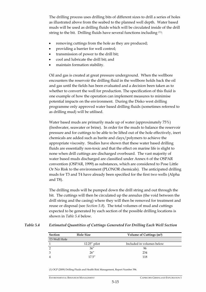
The drilling process uses drilling bits of different sizes to drill a series of holes as illustrated above from the seabed to the planned well depth. Water based muds will be used as drilling fluids which will be circulated inside of the drill string to the bit. Drilling fluids have several functions including (1): removing cuttings from the hole as they are produced; providing a barrier for well control; transmission of power to the drill bit; cool and lubricate the drill bit; and maintain formation stability. Oil and gas is created at great pressure underground. When the wellbore encounters the reservoir the drilling fluid in the wellbore holds back the oil and gas until the fields has been evaluated and a decision been taken as to whether to convert the well for production. The specification of this fluid is one example of how the operation can implement measures to minimise potential impacts on the environment. During the Disko west drilling programme only approved water based drilling fluids (sometimes referred to as drilling mud) will be utilised. Water based muds are primarily made up of water (approximately 75%) (freshwater, seawater or brine). In order for the muds to balance the reservoir pressure and for cuttings to be able to be lifted out of the hole effectively, inert chemicals are added such as barite and clays/polymers to achieve the appropriate viscosity. Studies have shown that these water based drilling fluids are essentially non-toxic and that the effect on marine life is slight to none when drill cuttings are discharged overboard. The vast majority of water based muds discharged are classified under Annex 6 of the OSPAR convention (OSPAR, 1999) as substances, which are considered to Pose Little Or No Risk to the environment (PLONOR chemicals). The anticipated drilling muds for T3 and T4 have already been specified for the first two wells (Alpha and T8). The drilling muds will be pumped down the drill string and out through the bit. The cuttings will then be circulated up the annulus (the void between the drill string and the casing) where they will then be removed for treatment and reuse or disposal (see Section 5.8). The total volumes of mud and cuttings expected to be generated by each section of the possible drilling locations is shown in Table 5.4 below.
Table 5.4 Estimated Quantities of Cuttings Generated For Drilling Each Well Section
Section Hole Size Volume of Cuttings (m3) T3 Well Hole 1 12.25” pilot Included in volumes below 2 36” 96 3 26” 234 4 17.5” 118
(1) OGP (2009) Drilling Fluids and Health Risk Management, Report Number 396.

ENVIRONMENTAL RESOURCES MANAGEMENT CAPRICORN GREENLAND EXPLORATION 1
5-16
Section Hole Size Volume of Cuttings (m3) 5 12.25” 47 6 8.5” 76
TOTAL 571 T4 Well Hole 1 12.25” pilot Included in volumes below 2 36” 96 3 26” 156 4 17.5” 183 5 8.5” 40
TOTAL 475 T16 Well Hole 1 12.25” pilot Included in volumes below 2 36” 96 3 26” 231 4 17.5” 56 5 8.5” 39 TOTAL 422 3557 T23 Well Hole 1 12.25” pilot Included in volumes below 2 36” 96 3 26” 254 4 17.5” 134 5 8.5” 64 TOTAL 548 3557
Once each section of the hole has been drilled, the drill string will be lifted out and the casing will be lowered into the hole and cemented into place. The cement will be mixed with small quantities of chemicals (see Section 5.10) on the MODU prior to being pumped down the hole and forced into the annulus. Table 5.5 below presents the estimated volumes of cement required for each of the possible drilling locations for the third and fourth wells.
Table 5.5 Estimated Cement Required for Wells Casings
Hole Size Length (m) Quantity of Cement (Metric Ton - MT)
T3 Well Hole 36” 380 – 453 152 26” 453 – 794 140 17.5” 794 – 1300 85 12.25” 1300 – 1710 50 8.5” 1710 - 3300 50 Plugs 103 Total 580 T4 Well Hole 36” 485 – 558 152 26” 558 – 785 120 17.5” 785 – 1570 95 8.5” 1570 - 2400 50 Plugs 103 Total 520 T16 Well Hole 36” 631 – 704 152 26” 704 – 1041 160 17.5” 1041 – 1280 75

ENVIRONMENTAL RESOURCES MANAGEMENT CAPRICORN GREENLAND EXPLORATION 1
5-17
Hole Size Length (m) Quantity of Cement (Metric Ton - MT)
8.5” 1280 – 2100 50 Plugs 104 Total 580 T23 Well Hole 36” 432 - 505 152 26” 505 – 875 175 17.5” 875 – 1450 105 8.5” 1450 - 2800 60 Plugs 103 Total 596
5.8 MUD AND CUTTINGS DISPOSAL
Disposal of muds and cuttings will be made to the seabed during the initial sections of the drilling when an open hole is accessed on the seabed around the well bore. The quantities of mud and cuttings released and dispersion models for mud and cuttings discharge are detailed within the Impact Assessment section of the EIA. Subsequent sections will be cased below the surface and drilled using a riser whilst circulating the drilling mud as described above to remove the cuttings from downhole. A blow-out preventer (BOP) will also be fitted on the seabed at the base of the riser. The riser allows the muds and cuttings from subsequent well sections to be returned to the drill unit where they will be separated and passed through the treatment system. The cuttings will be cleaned of the drilling fluid and discharged overboard to the sea via a caisson (discharge pipe), and the muds will be retained and recycled. The onboard mud treatment facilities on the Stena Forth drill ship comprise: 5 Thule Twin Deck Shale Shakers; a mud cleaner desilter; and a mud centrifuge. Onboard mud treatment facilities on the Stena Don semi-submersible comprise four Shale Shakers. The discharge route for the treated cuttings is shown in Table 5.6 below. A simplified schematic for the various well options to demonstrate the different well diameters and quantities of cuttings generated is provided in Figure 5.8. At the end of the drilling programme, the water based drilling muds will be discharged to sea.
Table 5.6 Discharge Location for Cleaned Cuttings
Section Hole Size Discharge Location T3 Well Hole 1 36” Seabed 2 26” Seabed 3 17.5” Surface

ENVIRONMENTAL RESOURCES MANAGEMENT CAPRICORN GREENLAND EXPLORATION 1
5-18
Section Hole Size Discharge Location 4 12.25” Surface 5 8.5” Surface T4 Well Hole 1 36” Seabed 2 26” Seabed 3 17.5” Surface 4 8.5” Surface T16 Well Hole 1 36” Seabed 2 26” Seabed 3 17.5” Surface 4 8.5” Surface T23 Well Hole 1 36” Seabed 2 26” Seabed 3 17.5” Surface 4 8.5” Surface
Water based muds will be used throughout the drilling campaign and there will therefore be no oil on cuttings from the drilling materials. Any oil on cuttings from the geological formation encountered during drilling will be separated on the drilling unit using the treatment systems described above. Where there is the potential for residual oil on the cuttings following treatment, the discharge will be visually monitored and controlled as per Capricorn’s policy on discharge of cuttings to sea; “When drilling with Water Based Mud (WBM) drill cuttings shall be monitored, handling and treated to assure no hydrocarbon contaminated cutting are discharged overside that will result in an oil sheen on the sea surface”.

Figure 5.8 Well Schematic for Calculating Cuttings from T3, T4, T16 and T23 Wells
ENVIRONMENTAL RESOURCES MANAGEMENT CAPRICORN GREENLAND EXPLORATION 1
5-19

ENVIRONMENTAL RESOURCES MANAGEMENT CAPRICORN GREENLAND EXPLORATION 1
5-20

ENVIRONMENTAL RESOURCES MANAGEMENT CAPRICORN GREENLAND EXPLORATION 1
5-21
5.9 WELL CLEANING, TESTING AND COMPLETION
If drilling results indicate the presence of hydrocarbons, the wells may subsequently be tested. Well testing represents a major source of data to engineers and geoscientists investigating the viability of the reservoir. Testing involves a range of techniques for establishing the characteristics of the reservoir and fluid such as pressure, temperature and flow rate. Testing equipment (the test string) will be run down the hole and initial reservoir data acquired. Where required, there will be a controlled flow of hydrocarbons back to the drill unit where they will be tested and subsequently flared. The likelihood of flaring being undertaken is estimated by the project team at less than 6% per well. The exact volume of hydrocarbons to be flared during any testing period will not be known until the well is tested. However, estimated figures provide an oil flow rate of 15,000bpd, or if gas is encountered, 40mmscfd (million standard cubic feet per day). Each zone of interest is likely to be tested, with an estimated 48 hours of total flow time per well spread over a period of up to 5 days. Total flared volume from each well would therefore be expected to be around 30,000 barrels (4,770m3) of oil, or 80mmscfd of gas. Inefficient combustion of oil can lead to black smoke emissions and un-combusted hydrocarbons falling onto the sea surface (known as “drop out” or “carry over”). The well test flare would be continually monitored for signs of incomplete combustion and compressed air used to aid the combustion process. An oil recovery vessel with full dispersant capability will be on stand by during well test flaring. Before any flaring can be carried out, a flaring consent must be applied for and issued by the BMP. It is also planned to acquire a Vertical Seismic Profile (VSP) at each well location. Acquisition of VSP data is used to provide additional seismic information and tie together the well data and the seismic data. Various types of VSP exist, however in the majority of cases a seismic source is generated at the surface using an airgun, with the receiver array positioned in the well. The duration of a VSP is far shorter than a standard seismic survey, normally lasting less than a day as opposed to several months. Following completion, the wells will be plugged and suspended in accordance with Norsok D-010. Wells will be suspended with full isolation across all hydrocarbon and abnormally pressurized zones. Each well with have an industry standard wellhead. Should the wellheads be left in place, well head protection will be installed to prevent damage to or from the wellhead due to snagging or collision. The wellhead protection will consist of a metal structure covered in grating to prevent snagging and
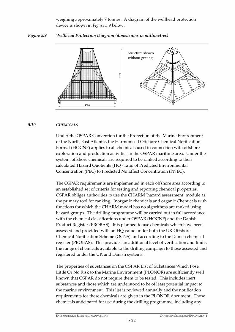
weighing approximately 7 tonnes. A diagram of the wellhead protection device is shown in Figure 5.9 below.
Figure 5.9 Wellhead Protection Diagram (dimensions in millimetres)
Structure shown without grating
5.10 CHEMICALS
Under the OSPAR Convention for the Protection of the Marine Environment of the North-East Atlantic, the Harmonised Offshore Chemical Notification Format (HOCNF) applies to all chemicals used in connection with offshore exploration and production activities in the OSPAR maritime area. Under the system, offshore chemicals are required to be ranked according to their calculated Hazard Quotients (HQ - ratio of Predicted Environmental Concentration (PEC) to Predicted No Effect Concentration (PNEC). The OSPAR requirements are implemented in each offshore area according to an established set of criteria for testing and reporting chemical properties. OSPAR obliges authorities to use the CHARM ‘hazard assessment’ module as the primary tool for ranking. Inorganic chemicals and organic Chemicals with functions for which the CHARM model has no algorithms are ranked using hazard groups. The drilling programme will be carried out in full accordance with the chemical classifications under OSPAR (HOCNF) and the Danish Product Register (PROBAS). It is planned to use chemicals which have been assessed and provided with an HQ value under both the UK Offshore Chemical Notification Scheme (OCNS) and according to the Danish chemical register (PROBAS). This provides an additional level of verification and limits the range of chemicals available to the drilling campaign to those assessed and registered under the UK and Danish systems. The properties of substances on the OSPAR List of Substances Which Pose Little Or No Risk to the Marine Environment (PLONOR) are sufficiently well known that OSPAR do not require them to be tested. This includes inert substances and those which are understood to be of least potential impact to the marine environment. This list is reviewed annually and the notification requirements for these chemicals are given in the PLONOR document. Those chemicals anticipated for use during the drilling programme, including any
ENVIRONMENTAL RESOURCES MANAGEMENT CAPRICORN GREENLAND EXPLORATION 1
5-22
ENVIRONMENTAL RESOURCES MANAGEMENT CAPRICORN GREENLAND EXPLORATION 1
5-23
contingency chemicals, are shown in the full chemical list provided in Annex D.
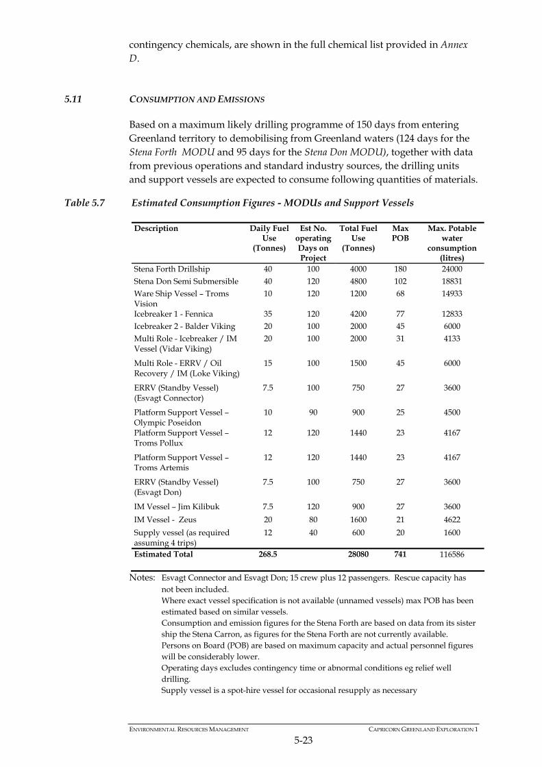
5.11 CONSUMPTION AND EMISSIONS
Based on a maximum likely drilling programme of 150 days from entering Greenland territory to demobilising from Greenland waters (124 days for the Stena Forth MODU and 95 days for the Stena Don MODU), together with data from previous operations and standard industry sources, the drilling units and support vessels are expected to consume following quantities of materials.
Table 5.7 Estimated Consumption Figures - MODUs and Support Vessels
Description Daily Fuel Use
(Tonnes)
Est No. operating Days on Project
Total Fuel Use
(Tonnes)
Max POB
Max. Potable water
consumption (litres)
Stena Forth Drillship 40 100 4000 180 24000 Stena Don Semi Submersible 40 120 4800 102 18831 Ware Ship Vessel – Troms Vision
10 120 1200 68 14933
Icebreaker 1 - Fennica 35 120 4200 77 12833 Icebreaker 2 - Balder Viking 20 100 2000 45 6000 Multi Role - Icebreaker / IM Vessel (Vidar Viking)
20 100 2000 31 4133
Multi Role - ERRV / Oil Recovery / IM (Loke Viking)
15 100 1500 45 6000
ERRV (Standby Vessel) (Esvagt Connector)
7.5 100 750 27 3600
Platform Support Vessel – Olympic Poseidon
10 90 900 25 4500
Platform Support Vessel – Troms Pollux
12 120 1440 23 4167
Platform Support Vessel – Troms Artemis
12 120 1440 23 4167
ERRV (Standby Vessel) (Esvagt Don)
7.5 100 750 27 3600
IM Vessel – Jim Kilibuk 7.5 120 900 27 3600
IM Vessel - Zeus 20 80 1600 21 4622
Supply vessel (as required assuming 4 trips)
12 40 600 20 1600
Estimated Total 268.5 28080 741 116586
Notes: Esvagt Connector and Esvagt Don; 15 crew plus 12 passengers. Rescue capacity has not been included.
Where exact vessel specification is not available (unnamed vessels) max POB has been estimated based on similar vessels.
Consumption and emission figures for the Stena Forth are based on data from its sister ship the Stena Carron, as figures for the Stena Forth are not currently available.
Persons on Board (POB) are based on maximum capacity and actual personnel figures will be considerably lower.
Operating days excludes contingency time or abnormal conditions eg relief well drilling.
Supply vessel is a spot-hire vessel for occasional resupply as necessary

ENVIRONMENTAL RESOURCES MANAGEMENT CAPRICORN GREENLAND EXPLORATION 1
5-24
Water will be needed for operational and domestic use onboard the Stena Forth, Stena Don, the Ware Ship and support vessels. Drilling will be undertaken using water based muds and it is estimated that approximately 1,590 m3 (10,000 barrels) of drilling water will be required per well. Based on published figures from the Norwegian Institute of Public Health1 it is estimated that approximately 200 Litres of potable water per person per day is required for a typical drilling operation. Regular and predictable potable water re-supply will be accessed from Greenlandic ports. Drilling water will be sourced from the ocean. The anticipated total fuel consumption during project operations is approximately 28,000 tonnes. Under the project plan for logistical support, fuel will be sourced from Greenlandic ports via Royal Arctic Line and arctic grade low sulphur fuels (≤ 1.5% sulphur content) will be used for both drilling units and support vessels. Sikorsky S92 and S61 helicopters will be used to provide Search and Rescue (SAR) and crew-change support for the drilling operations. Fuel capacity and consumption figures for the support helicopters are as follows: Sikorsky S61 (15 person capacity): Fuel capacity 2,475 litres, maximum range 1,111 km. Average fuel consumption 0.45km/l fuel. Sikorsky S92 (19 person capacity): Fuel capacity 3,974 litres (with auxiliary tanks), maximum range 1,389 km. Average fuel consumption 0.35km/l fuel. Actual fuel consumption will vary with payload, weather, speed etc. however taking average distance to the drilling area from the onshore base as 370km, average fuel consumption of 0.4 km/l fuel and operating two flights per day five days per week, an approximate figure for weekly helicopter fuel consumption would be: 18,500 litres. Fixed wing aircraft will also be used to provide crew transfers from Kangerlussuaq to Aasiaat. The type and estimated fuel consumption of this aircraft is not currently known, however the distance from Kangerlussuaq- Airport to Aasiaat Airport as the crow flies is 207 km, so the expected one return flight per day from Kangerlussuaq to Aasiaat five days per week would equate to just over 2000 km of direct flying for the fixed wing support aircraft.
5.11.1 Waste
Waste produced by the MODUs will be segregated and managed according to the category of waste material as described below and within the framework of the overall Project Waste Management Plan. The plan will set out clear responsibilities, starting at the point of waste production. Similar
(1) Water Report 113 Safe, Sufficient and Good Potable Water Offshore. A guideline to design and operation of offshore potable water systems. 2009. Norwegian Institute of Public Health.

ENVIRONMENTAL RESOURCES MANAGEMENT CAPRICORN GREENLAND EXPLORATION 1
5-25
considerations will apply to the supply and standby vessels although these will clearly generate much smaller volumes of waste. Waste materials will be appropriately contained, secured and labelled for transfer by support vessel to Arctic Base Supply (Royal Arctic Line/Danbor) for re-use, recycling (eg metal waste), treatment and/or disposal (eg incineration). All waste transfers will be accompanied by the required documentation. Refer to Section 5.12.6 for further details of Waste Management. This plan has been produced for the initial two wells and will be modified as necessary to accommodate any changes to the activities for the subsequent wells. Type 1 - Non- Hazardous Solid Wastes (controlled waste) This category includes pallets, plastics, packaging waste etc. The main sources are industrial refuse (packaging, cleaning materials etc) and maintenance wastes (filters, sandblast grits etc). Type 2 – Oil Contaminated Materials (hazardous waste) This category includes filters, absorbents etc. The main sources are spill clean up and greases and fuel oils. Absorbents will be minimised to that required to control the spill. Any used absorbent will be placed in a labelled drum and stored in a secure location pending removal ashore. The supervisor will ensure the label describes the substances spilled. Type 3 - Waste Oil (hazardous waste) This category includes lube oil, hydraulic oils, grease etc. The main sources are equipment lube oil changes. The engine lube oil tank will be used to store other sources of waste oil pending periodic removal and replacement. All waste oil produced and held on-board for subsequent transfer and disposal will be recorded in the waste oil log in accordance with MARPOL standards. Type 4 - Scrap Metals (controlled waste) The main sources are used process equipment/used tanks, electrical cables, empty drums, used tubulars, used casing etc. Under the Waste Management Plan, scrap metal will be made as clean as possible of contaminating oil and grease, with such oily wastes consigned to Waste Type 2 for disposal. If suitable cleaning is not feasible the container will be treated as hazardous (see below) and managed accordingly. Type 5 - Hazardous Materials (hazardous waste) This category includes excess/contaminated drilling and other chemicals, uncleaned drums/containers etc. The main sources are maintenance and drilling activities. Materials consigned to the hazardous waste skip must be compatible, undamaged and securely contained. Damaged containers will be washed clean. Where possible and safe to do so metal drums and containers will be washed before placing them in the scrap metal skip, or in the non-hazardous waste skip if non-metal. Washings will be contained within the hazardous drainage areas, providing that any residues that would pass through the hazardous drains separator are acceptable for discharge. Type 6 – Clinical Wastes

ENVIRONMENTAL RESOURCES MANAGEMENT CAPRICORN GREENLAND EXPLORATION 1
5-26
This category includes dressings, clinical and cleaning materials, blood samples, pathogenic organisms, plastic, glass, medicines, needles etc. The main sources are the MODU’s medical treatment facilities.
Table 5.8 Estimated Figures for Waste Production from the MODUs
Modelled waste production based on Project duration (kg) and annual waste production figures
Description Est No. operating Days on Project
Controlled Waste
Hazardous Waste
Clinical Waste
Total Waste
Stena Forth Drillship 100 41806 38491 10.7 80309 Stena Don Semi Sub 120 49822 95105 1.8 144931 Total Estimated Figure 91628 133596 12.5 225240
Note: Consumption and emission figures for the Stena Forth are based on data from its sister ship the Stena Carron, as figures for the Stena Forth are not currently available.
5.12 SUPPORT OPERATIONS
5.12.1 Personnel
A breakdown of the maximum Persons on Board (POB) for the various vessels and MODUs has been provided in Table 5.7 above. This is based on the maximum number of persons each vessel or rig can accommodate (excluding emergencies) and the actual number of personnel working offshore will be considerably less. Logistics provision is being made for an estimated 400 persons per month to crew change on and off the operations. Crew on the drill units will work on a rotation basis of 28 days on, 28 days off. All personnel working offshore will be in possession of appropriate emergency training and medical certification.
5.12.2 Support Vessel Characteristics
Introduction
Approximately twelve vessels in total, in addition to the two MODUs will be selected to provide for requirements and flexibility, including support of the operation and to provide cover for emergency stand-by, ice management / anchor handling, oil spill response, ice breaking and re-supply. This will include the following: 1 x accommodation vessel / warship; 2x icebreaker vessels; 1 multi role icebreaker and Ice Management (IM) vessel; 1 multi role Emergency Response and Rescue Vessel (ERRV), Oil Recovery
and Ice Management Vessel; 2 x Ice Management Vessels 2 x ERRV Standby vessels; and 3 x Platform Supply Vessel (PSV).

ENVIRONMENTAL RESOURCES MANAGEMENT CAPRICORN GREENLAND EXPLORATION 1
5-27
The drilling operations are therefore supported by a range of vessels designed not just to provide day-to-day platform support and resupply, but also equipped to act as icebreakers, ice management vessels, emergency response and rescue, oil recovery and tugs. The vessels will be equipped with sufficient primary oil spill contingency equipment to deal with spills as outlined in the site specific oil spill contingency plan. Drilling support vessels work on a worldwide basis and as such the crew is internationally based. The exact nationality of the crew is as yet undetermined, however it is unlikely that personnel on the vessels will be sourced short term from Greenland due to the term of the project and the specialist skills required. Ware Ship (Troms Vision)
The principal supply method is via a ‘Wareship’ (the MV Troms Vision) to carry all the supplies and contingency equipment for the drilling campaign (see Figure 5.10) as will be used for Alpha and T8 wells. The MV Troms Vision is a subsea construction support vessel with around 1,000 m2 upper deck area. The ship is equipped with two 100 t offshore cranes and two 3t deck cranes. The ship will also provide a standby flotel facility with accommodation capacity for over 50 personnel for delayed crew changes to avoid any potentially disruptive onshore interactions can also be used as an emergency response staging post. It is anticipated that during the project there will be a full marine crew of 18. Up to 50 persons are anticipated to be temporarily housed during crew changes. It is anticipated that personnel will access the ship either via helicopter or crew change tender. There will be no free access between the Ware Ship and shore which will minimise the interaction between foreign workers and local communities and businesses. Organic waste from the Ware Ship will be macerated and treated before discharge and non organic waste will be compacted and shipped to Arctic Base Supply reception facilities in Aasiaat (onshore) for disposal (see Section 5.11.1). The Ware Ship is anticipated to arrive in June 2010 and depart at the end of the drilling programme.
5.12.3 Onshore Supply Base
The Stena Forth will load equipment and supplies at Peterhead in Scotland, with St John’s Newfoundland the back up supply base in the event of delays. The wareship will also load supplies and equipment before mobilising to Greenlandic waters. The Stena Don will transit basically empty to ensure the pontoons are out of the water to improve surface transit speed.

ENVIRONMENTAL RESOURCES MANAGEMENT CAPRICORN GREENLAND EXPLORATION 1
5-28
Aasiaat has been identified as the preferred forward base for helicopter transfer of crews to the rigs and 24 hr Search and Rescue (SAR) operations, and with Ilulissat as the hanger base for helicopter operations (approximately 2 helicopter flights per day). Crews will be transferred to Aasiaat by fixed wing aircraft from the international airport in Kangerlussuaq. Nuuk has been identified as the preferred base for refuelling and water supplies. Figure 5.10 shows the locations of onshore support facilities in relation to the licence area. Arctic Shore Base (ABS), a joint venture between Royal Arctic Line and Danbor, operate onshore supply base facilities in Aasiaat which will be utilised for the project, the base will provide the following: Limited laydown and loading / unloading of supply boats – of which
there are likely to be 1-2 per week. Waste handling / disposal facilities. Transport of materials to support onshore base operations (between RAL
locations and airports). Additional personnel with skills. Storage for part of the Oil Spill Response equipment. There will be onshore accommodation in Aasiaat for up to 12 Capricorn personnel. ABS are the preferred supplier for local logistics interaction and management. Similarly, Air Greenland will be contacted for air supply transportation logistics, with helicopter services by Cougar based in Ilulissat and transferring crews out of Aasiaat (see Figure 5.11).

®q
EE
E
E
Nuuk
NarsaqQaqortoq
Aasiaat
Ilulissat
Kangerlussuaq
CLIENT: SIZE: TITLE:
DATE: 28/06/2010
DRAWN: CJ
CHECKED: RB
APPROVED: JP
PROJECT: 0108885
As scale barDRAWING: REV:
KEY: Capricorn Greenland Exploration-1 A4 Figure 5.10
Onshore Support Facilities
5.11_OnshoreSupportFacilities.mxd 0
Licence AreaE Well location
SOURCE: Capricorn Greenland Exploration-1PROJECTION: WGS 1984 UTM Zone 21N
File:
0108
885G
reenla
ndW
estG
IS_C
J_JP
\Map
s\Well
3 an
d 4\5.
11_O
nsho
reSup
portF
acilit
ies.m
xd
ERMEaton HouseWallbrook CourtNorth Hinksey LaneOxford, OX2 0QSTelephone: 01865 384800Facsimile: 01865 204982.0 200
Kilometres© ERM This print is confidential and is supplied on the understanding that it will be used only as a record to identify or inspect parts, concepts or designs and that it is not disclosed to other persons or to be used for construction purposes without permission.

Figure 5.11 Aasiaat Helicopter Base
5.12.4 Offshore Supplies
Offshore activities will be located in excess of 100km from the nearest land. Therefore all drilling units will arrive and depart well locations without planned land fall. Instead they will be serviced regularly by supply boats. Potable water, food and fuel will be re-supplied via Greenlandic ports, all other materials and consumables will be supplied from the UK. Oil spill equipment will be stored at the onshore supply base in Aasiaat, on the Troms Vision wareship and will be flown to site as required. Please refer to the drilling campaign Oil Spill Response Plan for full details of response planning and contingency materials.
5.12.5 Helicopters and Support Aircraft
In compliance with the exploration strategy, Capricorn intends to use the best helicopter equipment which includes S92’s with full search and rescue (SAR) capability including night/poor weather auto hover recovery. These aircraft will have a maximum of one hour scramble capability to reflect the harsh weather environment. The helicopters will be used to transfer crew to the rigs from Aasiaat. Aasiaat is the forward base for helicopters, while hangerage (not required in summer) and maintenance facilities will be provided in Ilulissat The helicopter flight and ground crew are estimated to be 30 people, housed in hotel accommodation in Ilulisat. The base case is that Cougar Helicopters, of St Johns, Newfoundland, Canada will be the helicopter provider. Kangerlussuaq international airport has landing for Tier 3 Oil Spill Response equipment and a 60 person camp as contingency for delayed flights will be made available.
ENVIRONMENTAL RESOURCES MANAGEMENT CAPRICORN GREENLAND EXPLORATION 1
5-30

Aircraft support for the operations will consist of the following: 1 Sikorsky S92 providing SAR Support (Figure 5.12); 1 Sikorsky S92 providing SAR and crew-change support; 1 Sikorsky S61 providing SAR and crew-change support (Figure 5.12); and Fixed wing aircraft providing crew transfer from Kangerlussuaq to
Aasiaat. The forward base for helicopters will be at Aasiaat with fixed wing aircraft based at Kangerlussuaq. It is anticipated that the crew-change helicopters (S61 and S92) will each make one return flight per day to the Sigguk Licence Area five days per week, with the fixed wing aircraft also making one return flight per day from Kangerlussuaq to Aasiaat five days per week.
Figure 5.12 Sikorsky S92 (left) and S61 (right) Support Helicopters
5.12.6 Waste Management
Waste materials will be separated offshore into hazardous and non-hazardous wastes (solids and liquids). Clinical waste will also be segregated and stored separately. These wastes will be segregated in accordance with MODU and vessel waste management arrangements and the specially develop project Waste Management Plan (WMP). Each of the ports can cater for hazardous and non-hazarodous waste management. In most circumstances hazardous waste will be sent to ABS then on to Denmark for disposal whereas non-hazardous waste will disposed locally where possible (see Section 5.11.1). The WMP has been developed for the project and submitted as part of the Alpha and T8 well application, will be modified in line with any changes to the project (eg addition or change in vessels)
ENVIRONMENTAL RESOURCES MANAGEMENT CAPRICORN GREENLAND EXPLORATION 1
5-31

ENVIRONMENTAL RESOURCES MANAGEMENT CAPRICORN GREENLAND EXPLORATION 1
5-32
5.13 OTHER DEVELOPMENT OPTIONS
An important element of the impact assessment is the consideration of project alternatives. In accordance with the applicable legislation and guidance in Greenland, this section also examines possible scenarios should the drilling programme be successful and future development shown to be both commercially and technically viable. Although this information is provided to give an example of the future possibilities, the scope of both the environmental and social impact assessment remains limited to the actual 2010 exploration drilling programme.
5.13.1 Alternatives
The selection and alternatives for drilling locations, drill units and mud selection are described below. One alternative to be considered is the No Development Option, or what will the implications be (both positive and negative) should exploration drilling not proceed. The baseline will not remain static and likely future trends in the environmental and socio-economic baseline are accounted for in the impact assessment process (see Chapter 3 of the EIA for the Assessment Methodology and Chapter 6 for the Impact Assessment). In the No Development Option the potential impacts of offshore drilling identified within the EIA and SIA will not occur, however it should be recognised that the baseline will continue to be impacted by, for example, fishing and hunting, vessel activity, natural impacts such as iceberg movement or sedimentation, waste materials, sewage and polluted run-off, fall out of atmospheric pollutants or accidental releases and spills. In the case of No Development, the exploration for and possible realisation of hydrocarbon resources will not take place. Potential revenue and employment from any future development will not be realised and the potential benefits to local businesses and communities from oil and gas activity will not take place. No Development will therefore inhibit offshore exploration activity and the potential future development of hydrocarbon resources, together with the possible benefits it may bring to the country; however it will also prevent the identified potential impacts of drilling activity from occurring, although the baseline environment will continue to be altered by other factors. Drilling Locations
The drilling locations for the 2010 Disko West drilling campaign by Capricorn have been selected based on extensive geophysical; data acquisition and interpretation. Seismic exploration, electro-magnetic surveys, site surveys and environmental surveys have all been undertaken to provide information on the water column, seabed and particularly on the subsurface. A summary of the petroleum geology is provided in Section 5.5. The presence of commercially viable hydrocarbon reserves is a complex interaction of many factors including time, pressures, source rock, reservoir rock, migration

ENVIRONMENTAL RESOURCES MANAGEMENT CAPRICORN GREENLAND EXPLORATION 1
5-33
pathways and impermeable traps all of which need to be accounted for in interpreting the geophysical data and deciding whether, and where, to drill. The identified drilling locations are therefore based on extensive geological and geophysical studies. Although these remote studies can provide petroleum geologists with a good idea of the subsurface and an indication of where to drill, it is only through exploration drilling that the interpretation can be verified and actual subsurface data acquired. Rig Selection
Both of the drilling units selected for this work are modern rigs designed for work in harsh environments at the water depths encountered in the Disko West area. Both units are operated by Stena Drilling Limited (Stena). Further technical details are provided in Section 5.4. The Stena Forth is a state-of-the-art (sixth generation) dynamically
positioned drillship designed for year-round operations in deep waters and harsh environments (operating at temperatures down to -20degC).
The Stena Don is a dynamically positioned (class 3), harsh environment
semisubmersible drilling vessel designed for worldwide operations. The drilling units have been selected based on their technical suitability for the water depths, drilling depths and environmental conditions of the Disko West area, and availability to conduct the operations. Mud and Chemical Selection
During drilling, muds are used for several purposes (as weighting agents to control down-hole pressure, to lubricate and cool the drill bit and to carry the cuttings to the surface for disposal). The drilling muds are formulated according to the well design and geological conditions expected. They comprise a base fluid, weighting agents and chemicals that are used to give the mud the exact properties it needs to make it as easy and safe as possible to drill. In addition to the operational characteristics, the muds are selected on the basis of ecological toxicity and bio-degradation rates. Water based mud systems have been selected for the exploration wells (as opposed to more harmful oil based systems) along with low-toxicity and inert chemicals as described in more detail with the Project Description.
5.14 LIFECYCLE OF ACTIVITIES
The current impact assessments (social and environmental) encompass short term exploration drilling activities and the associated support operations. Should exploration drilling be successful and sufficient reserves of
ENVIRONMENTAL RESOURCES MANAGEMENT CAPRICORN GREENLAND EXPLORATION 1
5-34
hydrocarbons found, a number of development options exist which will be the subject of future environmental studies at the appropriate time. Previous operational studies have been carried out looking at the possible development options for hydrocarbon resources offshore Greenland by a number of organisations, including: APA Petroleum Engineering (2003); US Geological Survey (USGS) (2008); Genesis Oil and Gas (2009); and Aker Engineering & Technology (2005 and 2008). For the purposes of this analysis of potential future development scenarios, the 2008 study by Aker Solutions (“Disko-West Opportunity Appraisal Study Report”) has been used as the primary information source. This study is focussed on the current Project area and was commissioned by Cairn, so is the most accurate current reflection of the high level technical and economic scenarios which may be considered by Cairn at some point in future should economically viable hydrocarbon reserves be found. It should be recognised that given the very early stage of the exploration and development process, these scenarios may well change and the strengths and weaknesses of each scenario are also likely to vary depending on the findings of exploration and appraisal drilling. This summary of potential development scenarios is therefore based on the current state of knowledge and a large number of assumptions regarding the subsurface conditions. The main assumption for future development is that hydrocarbon resources will be found in quantities sufficient to be economically viable for development, the qualities of the hydrocarbon and reservoir characteristics make extraction a technically and economically feasible option and that any potential technical constraints for operating in this area can be overcome. For the Disko West area, assuming the most likely scenario that oil rather than gas is discovered, the options for future development examined in the Opportunity Appraisal Study Report include the following: A Floating Production Unit (FPU) or a Floating Production, Storage and
Offloading vessel (FPSO) located at the field. This would allow export of the product directly from the field to reception terminals elsewhere, without the requirement for onshore processing/receiving facilities.
Subsea development offshore and a tieback (pipeline) to an onshore plant,
with oil transportation from the plant to market via ice-breaking tankers delivering the crude to an existing transhipment terminal.
A FPU located at the field with a pipeline to remote storage facilities in an
ice-free area with tankers delivering crude to reception terminals elsewhere.

ENVIRONMENTAL RESOURCES MANAGEMENT CAPRICORN GREENLAND EXPLORATION 1
5-35
Options for a semisubmersible, a traditional Tension Leg Platform (TLP), a deepwater gravity based structure or a spread moored barge were examined in one of the studies but discounted. These options are not considered further within this chapter.
Any future development of hydrocarbon resources in this area will likely require considerable support from onshore Greenland. The nature and extent of onshore support services, infrastructure, personnel and facilities will vary widely with the nature and size of any development. It should be noted that offshore field development is a long process, taking a number of years from successful drilling to first output (10 years or more in many instances) and that many more studies into these options will be undertaken over this period should viable reserves be discovered. A current assessment of the development studies by Capricorn concludes: Greenland field developments are likely to be in deep water in remote
iceberg prone Arctic areas, requiring leading edge technology, high expenditure and long schedules.
At present rock properties, fluid properties, well rates and field sizes are
all unknown. FPSO development scenarios are technically feasible and are the base case
for Greenland oil field developments. The subsea to shore development scenario merits further study. At this stage there is insufficient information to justify any particular
development option as the selected option. Several options are therefore technically feasible and potentially viable, depending on the outcomes of exploration drilling and further studies. The feasibility of the options depends to a large degree on specific site conditions and ice management. Some of the challenges with development in this area include: iceberg frequency and size; extent and properties of sea ice; and site conditions at the field;
5.14.1 Future Development Scenarios
The main scenarios for future development considered within the Disko-West Opportunity Appraisal Study Report include: Processing and storage in field (FPSO); Processing in field followed by pipeline to storage onshore; and Processing in field then pipeline to remote offshore storage.

These scenarios are discussed in further detail below. FPSO
These scenarios involve transporting oil from the FPSO by shuttle tankers. The first scenario is to use a ship shaped FPSO. With this scenario, both the production vessel and the oil export vessel will be located within the ice field.
Figure 5.13 Elevation Layout for Ship Shaped FPSO
For all the scenarios considered, the ‘production uptime’ (amount of time the FPSO is in production) is dependent on the performance in ice, particularly with regard to the frequency of disconnections and time to disconnect and reconnect. The disconnection and reconnection times are significantly shorter for a ship-shaped FPSO than for a geostationary FPSO. No additional vessels are required for reconnection other than those support vessels already in the field. However, the ship shaped FPSO will need an additional support vessel compared to the geostationary FPSO as it requires an icebreaking vessel for weathervaning. Offloading of oil would occur in the field for this scenario. As the facilities would be ice bound for a significant portion of the year, additional icebreaking shuttle tankers would be required. Alternatively, an icebreaking geostationary floater could be used with a submerged turret connected to the risers.
ENVIRONMENTAL RESOURCES MANAGEMENT CAPRICORN GREENLAND EXPLORATION 1
5-36

Figure 5.14 Elevation Layout for Geostationary FPSO
In this scenario, offloading of oil occurs through risers and a subsea pipeline to a submerged buoy. Whilst the geostationary FPSO only requires five support vessels during ice free periods, it will require two more icebreakers during the ice-bound season. The disadvantage of both of these scenarios is the risk of collision as large volumes of oil will be stored on the FPSO. There is also the potential for physical interference with any other marine users present in the area (eg tourist vessels, shipping traffic) and underwater noise will also need to be considered. Other potential environmental impacts from these options include the management of produced water associated with the hydrocarbons and greenhouse gas (GHG) emissions from the ongoing operation of vessels and machinery. The most significant potential impact would result from an emergency situation leading the uncontrolled release of hydrocarbons into the marine environment. Conversely, as operations would be maintained offshore they would be out of sight of land and have limited onshore interactions. Social impacts or onshore physical impacts would therefore be less significant. Shore Based Storage
Geostationary floater with pipeline to shore A geostationary floater facility or a ship shaped FPSO with a sheltered Gravity Based Structure (GBS) storage and export unit are possible scenarios as shown in the figures below.
ENVIRONMENTAL RESOURCES MANAGEMENT CAPRICORN GREENLAND EXPLORATION 1
5-37

Figure 5.15 Elevation Layout for Geostationary Floater with Sheltered Storage and Export Unit
Figure 5.16 Elevation Layout for Ship Shaped FPSO with Sheltered Storage and Export Unit
Full processing occurs offshore for this scenario, although oil storage is undertaken onshore. The FPU/FPSO can therefore be considerably smaller which increases flexibility and reduces disconnection and reconnection times. This scenario has reduced ice exposure in comparison to other scenarios as most of the oil is in storage onshore and does not become ‘trapped’ in the field during the ice-bound season. In addition, less specialised, larger tankers could be utilised to transport oil from shore. This would reduce the number of vessels required for transportation. There would likely be a lower level of potential ongoing environmental impact offshore as the units would be smaller, fuel consumption and sound emissions would be less and there would be only limited offshore storage of hydrocarbons. There would be impacts to the seabed from construction of the export pipeline and coastal storage, with the additional risk that any loading spills or major uncontrolled releases would occur in the shoreline environment where potential impacts to sensitive species such as seabirds or seals or protected/sensitive habitats could occur.
ENVIRONMENTAL RESOURCES MANAGEMENT CAPRICORN GREENLAND EXPLORATION 1
5-38

The use of coastal facilities would increase the visibility of the operation and could also increase impacts to coastal populations or other users of the coastal environment (eg tourism, fishing, vessel movements). Potential social or economic benefits may be enhanced by the use of nearshore operations, both through the construction phase and operational phase of the development. Offshore Storage
By transporting oil via a pipeline, it can be transported through the area with heaviest ice coverage to a remote loading station in an area that is free from ice most of the year. As with the shore based storage scenarios, a ship shaped FPSO or geostationary floater for this scenario can be smaller as less oil needs to be stored onboard thereby reducing the risk of oil loss due to ice and improving the manoeuvrability of the vessel. This scenario would require a pipeline of approximately 200 km in length. As the remote storage would be located in an ice-free location, slow moving ice breaking shuttle tankers would not be required. In addition, larger tankers could be utilised. This would reduce the number of tankers required.
Figure 5.17 Elevation Layout for Ship Shaped FPSO with Offshore Storage and Loading
ENVIRONMENTAL RESOURCES MANAGEMENT CAPRICORN GREENLAND EXPLORATION 1
5-39

Figure 5.18 Elevation Layout for Geostationary Floater with Offshore Storage and Loading
The use of an offshore storage and loading facility connected by an export pipeline to the FPU/FPSO would mean that the offshore sphere of influence would be increased (trough the presence of two main offshore units), with potentially greater impacts from interference with other sea users. There would also be seabed impacts from the construction of the connecting pipeline. The risk of coastal impacts would however be reduced by maintaining the project in an offshore location, although the risk of major releases of hydrocarbons would still exist. Collision risks would be mitigated to some extent by locating the storage and loading unit in an area free of ice, with a smaller and more manoeuvrable unit (FPU or FPSO) located at the production site. The effects on overall underwater sound and air emissions impacts from using two smaller units rather than one large FPSO are not known. The project would be located away from land and visibility of the operations to the onshore communities would therefore be low. As there would be limited onshore facilities the social or economic benefits of this option are expected to be less than for a coastal development, although as with all of the options described here there will still be a significant level of onshore support required, particularly in logistics, personnel movements, storage and supply of fuel and materials, service personnel, onshore accommodation and emergency response.
ENVIRONMENTAL RESOURCES MANAGEMENT CAPRICORN GREENLAND EXPLORATION 1
5-40

ENVIRONMENTAL RESOURCES MANAGEMENT CAPRICORN GREENLAND EXPLORATION-1
6-1
6 IMPACT ANALYSIS AND MITIGATION
6.1 INTRODUCTION
The discussion of project impacts, their mitigation and significance is a key factor in producing an EIA report that is both usable in the ongoing environmental management of the project and meaningful to stakeholders. This chapter addresses these requirements as follows. An ‘impact’ matrix (Figure 6.1) summarises scoping by identifying the
main interactions between project activities and environmental resources and receptors.
Based on the identified interactions, the impacts, their mitigation and
significance are summarised in Table 6.8. Key issues for the EIA are expanded upon at greater length in subsequent
sections of this Chapter. Key interactions and issues have been determined through ongoing scoping according to one or more of the following considerations: past experience in the context of offshore exploratory drilling; regulator and stakeholder concern; legislative requirement; professional judgment in regards to resources / receptors deemed as
sensitive to effects of the Project; and being exposed to impacts from large scale or multiple activities. In summary, the drilling programme will involve the mobilisation of drilling units and support vessels into Greenlandic waters. The vessels will use computer controlled thrusters to remain on station at pre-selected sites between 100 km and 200 km offshore in water depths of between 300 m and 600 m to drill exploration wells to various depths below the seabed. The drilling programme will last for around 3 months. There will be a movement of personnel and materials (eg fuel, water, waste) between the drilling area and west Greenland via support vessels and helicopters. Logistical support will be provided primarily by Royal Arctic Line. Once drilling has finished, the drilling units and support vessels will move away, leaving protected wellheads in place on the seafloor. The water depths in which the operations will take place are not considered particularly deep, although the Project is taking place in a fairly extreme operating environment requiring specialist equipment and procedures. Offshore drilling is a common activity which has been extensively studied and is well understood. The emissions and operating aspects of these activities are well documented, although the potential impacts will vary with the particular nature of the operating environment. A number of mitigation measures have

ENVIRONMENTAL RESOURCES MANAGEMENT CAPRICORN GREENLAND EXPLORATION-1
6-2
been incorporated into Project planning to address potential impacts and these are described in the following Chapter.
6.2 IMPACT IDENTIFICATION
The exploration drilling activities have the potential to affect the environment in a number of different ways. These will include physical disturbance, emissions and discharges and waste generation. Potential impacts are identified according to the process described in Chapter 3. The first step in impact identification has been to identify the various types of activity associated with the exploratory drilling, together with their associated emissions and discharges where appropriate. At a high level, the main sources of impact of the project can be divided into: planned events: physical disturbance, emissions, discharges and wastes; and unplanned events: unintentional releases, emergencies, accidents. The activities / sources of potential impact due to the project and the components of the receiving environment that could potentially be affected are identified in Figure 6.1 in the form of a matrix checklist. Since SIA is separate activity the main resource/receptors that can be potentially impacted are: offshore marine natural populations for planned project activities; and offshore and coastal populations for potential accidental events.

Figure 6.1 Potential Impacts
Source of Potential Impact
drilling vessel & rig passage & positioning
physical presence of vessel/rig
vessel/rig exclusion zone
support vessel passage
aircraft passage
shore base access
engine emissions
sewage / grey water
kitchen wastes etc
uncontaminated drainage
contaminated drainage
cement
spent mud
cuttings
garbage / trash
noise (including aircraft)light
chemical spillagefuel spillage
blowout / explosion
loss of material
Val
ue
d E
co
sys
tem
Co
mp
on
ent
ClimateWindNoiseAir QualitySeabed IntegrityOceanographyTides and CurrentsWavesTemperature and SalinitySea IcePolynyasIce BergsCoastal ZoneWater QualitySediment QualityPrimary Production (Plankton and Macrophyte Species)
Zooplankton SpeciesBenthic Invertebrate SpeciesFish SpeciesSeabird SpeciesMarine Mammal SpeciesImportant HabitatsEnvironmentally Sensitive and Designated AreasArchaeologyFisheriesTraditional Activities Infrastructure
Val
ue
d E
co
sys
tem
Co
mp
on
ent

ENVIRONMENTAL RESOURCES MANAGEMENT CAPRICORN GREENLAND EXPLORATION-1
6-4
6.3 IMPACTS FROM PLANNED EVENTS
6.3.1 Introduction
For convenience in treating the subject, impacts to the environment from planned events have been divided into three main areas as summarised in Box 6.1.
Box 6.1 Main Areas of Biodiversity Impact
1. Impacts due to the drilling vessel and other surface vessel activity (noise, movement, light) during drilling operations: the main resource/receptor groups that could be susceptible to impacts comprise marine mammals and to a lesser extent fish and seabirds.
2. Impacts due to discharges to sea: the main resource/receptor groups susceptible to impact
would be plankton and fish and their predatory fauna higher in the food chain. 3. Impacts due to the seabed footprint (including facilities and cuttings piles): the main
resource/receptor groups that could be susceptible to impacts comprise benthic fauna and bottom-dwelling fish that prey on them.
Potential environmental impacts that could occur in the event of an oil spill are discussed in Section 6.4 below.
6.3.2 Potential Sources of Impact
A number of activities will be taking place at the sea surface throughout the Project that will have potential disturbance effects on the following receptors: marine mammals (whales, dolphins and seals); polar bears; pelagic fish; and seabirds. Both MODUs will mobilise into Greenlandic waters under their own power (ie not requiring towing) and will remain on station at each well site through the use of dynamic positioning thrusters. Once on station there will be vessels undertaking ice breaking and ice management activities, regular supply vessels and stand-by vessels for the MODUs, helicopter operations for transporting personnel between the drilling operations and the shore, as well as fixed wing flights for in-country transfers between Kangerlussuaq and Ilulisat. At the end of drilling operations the drill units and vessels will demobilise under their own power. All the above-mentioned activities will generate noise and have potential disturbance effects on natural populations through physical movement and possibly light.

ENVIRONMENTAL RESOURCES MANAGEMENT CAPRICORN GREENLAND EXPLORATION-1
6-5
6.3.3 Noise Impacts
Potential Sources of Impacts
Both the Stena Forth and Stena Don are Dynamically Positioned Mobile Offshore Drilling Units (MODU) that do not require anchors to keep position. There will be supply vessels visiting the drilling ship and semi-submersible vessels 1-2 times a week, helicopter flights twice a day and one fixed wing flight per day to transport personnel primarily between the MODU, Ware Ship and onshore facilities. The MODUs will require support from ice management and ice breaker vessels and stand-by vessels. These vessels generate noise and vibration which may be conducted by air or through the water. The key sound sources are expected to include vessel propellers and thrusters, with a contribution from the hull (eg originating from marine and deck machinery). This is expected to result in highly variable sound levels, being dependent on the operational mode of each vessel. The key source of aerial noise will be from vessel diesel engines and helicopters. The main sources of noise from these activities can be categorised into the following: Propeller and thrusters: When vessels are travelling at speed cavitation can
occur around the blades of the propeller which causes noise. The thrusters used by Dynamically Positioned vessels emit noise when operating under load to maintain the vessel’s position. These activities normally produce broadband noise with some low tonal peaks.
Machinery noise: When the vessel is stationary or moving at low speeds the
dominant noise often comes from machinery such as large power generation units (diesel engines or gas turbines), compressors and fluid pumps. The noise tends to be of low frequency and tonal in nature. It can be transmitted through different pathways, ie structural (machine to hull to water) and airborne (machine to air to hull to water), or a mixture of both.
Equipment in water: Equipment such as flowlines and valves can produce
noise. Noise produced will tend to be relatively low for drill casing. Ice breaking: The breaking of ice emits noise at frequencies of 20 -1,000 Hz.
Ice breaking creates short loud pulses of underwater sound. Both drill ships and drill rigs produce low frequency underwater noise but drill ships are inherently louder than semi-submersible rigs as ships have a large hull area that contains most of their machinery. Semi-submersible rigs have their machinery mounted on decks above the sea and therefore do not emit as much noise through the water. Drill ships generate underwater sounds in the range of 10 Hz to 10 kHz with average source levels of 179-191 dB re 1 μPa-m whereas anchored semi-
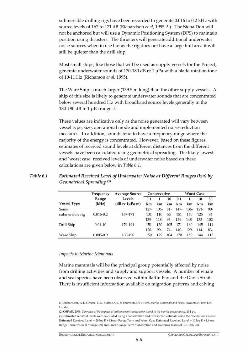
ENVIRONMENTAL RESOURCES MANAGEMENT CAPRICORN GREENLAND EXPLORATION-1
6-6
submersible drilling rigs have been recorded to generate 0.016 to 0.2 kHz with source levels of 167 to 171 dB (Richardson et al, 1995 (1)). The Stena Don will not be anchored but will use a Dynamic Positioning System (DPS) to maintain position using thrusters. The thrusters will generate additional underwater noise sources when in use but as the rig does not have a large hull area it will still be quieter than the drill ship. Most small ships, like those that will be used as supply vessels for the Project, generate underwater sounds of 170-180 dB re 1 μPa with a blade rotation tone of 10-11 Hz (Richarson et al, 1995). The Ware Ship is much larger (139.5 m long) than the other supply vessels. A ship of this size is likely to generate underwater sounds that are concentrated below several hundred Hz with broadband source levels generally in the 180-190 dB re 1 μPa range (2). These values are indicative only as the noise generated will vary between vessel type, size, operational mode and implemented noise-reduction measures. In addition, sounds tend to have a frequency range where the majority of the energy is concentrated. However, based on these figures, estimates of received sound levels at different distances from the different vessels have been calculated using geometrical spreading. The likely lowest and ‘worst case’ received levels of underwater noise based on these calculations are given below in Table 6.1.
Table 6.1 Estimated Received Level of Underwater Noise at Different Ranges (km) by Geometrical Spreading (3)
Conservative Worst Case
Vessel Type
Frequency Range (kHz)
Average Source Levels
(dB re 1μPa-m) 0.1 km
1 km
10 km
0.1 km
1 km
10 km
50 km
Semi-submersible rig 0.016-0.2 167-171
127-131
106-110
81-85
147-151
136-140
121-125
90-94
Drill Ship 0.01-10 179-191 139-151
118-130
93-105
159-171
148-160
133-145
102-114
Ware Ship 0.005-0.9 160-190 120-150
99-129
74-104
140-170
129-159
114-144
83-113
Impacts to Marine Mammals
Marine mammals will be the principal group potentially affected by noise from drilling activities and supply and support vessels. A number of whale and seal species have been observed within Baffin Bay and the Davis Strait. There is insufficient information available on migration patterns and calving
(1) Richardson, W.J., Greene, C.R., Malme, C.I. & Thomson, D.H. 1995. Marine Mammals and Noise. Academic Press Ltd,
London. (2) OSPAR, 2009. Overview of the impacts of anthropogenic underwater sound in the marine environment. 134 pp. (3) Estimated received levels were calculated using a conservative and ‘worst case’ estimate using the calculation: Lowest Estimated Received Level = 20 log R + Linear Range Term and Worst Case Estimated Received Level = 10 log R + Linear
Range Term, where R = range (m) and Linear Range Term = absorption and scattering losses of -0.61 dB/km.

ENVIRONMENTAL RESOURCES MANAGEMENT CAPRICORN GREENLAND EXPLORATION-1
6-7
areas to determine which species are likely to be found within the Sigguk block during the drilling period so a precautionary approach has been taken based on the general distribution of species throughout the year. All of the five species of baleen (or toothless) whales that have been recorded within western Greenland waters have the potential to be present within the Sigguk block during the drilling period. These baleen whales are low frequency hearing cetaceans that include: Bowhead whale, Balaena mysticetus Minke whale, Balaenoptera acutorostrata; Humpback whale, Megaptera novaeangliae; Fin whale, Balaenoptera physalus; and Blue whale, Balaenoptera musculus. The toothed whales and porpoises (odontocetes) which are mid or high frequency hearing cetaceans that may be present during drilling include: Harbour porpoise, Phocoena phocoena; Bottlenose whale, Hyperoodon ampullatus; Long-finned pilot whale, Globicephalus melas; Killer whale, Orcinus orca; Beluga whale, Delphinapterus laucas; and Sperm whale, Physeter macrocephalus. Four species of seal have the potential to be found within the Sigguk block during drilling. These are: Harp seal, Phoca groenlandica; Hooded seal, Cystophora cristata; Ringed seal, Phoca hispida; and Harbour seal, Phoca vitulina.
Research into the physical damage and behavioural response in marine mammals to noise and vibration generated by drilling activities and vessels is limited and does not provide sufficient agreement between studies to be able to confidently determine which activities and sound levels elicit a response by the animal and which observed behaviours are in response to external factors. For example, studies by Richardson et al (1995) found toothed whales showed both avoidance and attraction to drilling activities. Marine mammals are unlikely to intentionally approach operations producing continuous or semi-continuous sounds that are powerful enough to lead to auditory damage. That is, marine mammals are expected to avoid continuous or semi-continuous sound sources that may cause harm, including any potentially arising from the Project. The rest of this assessment therefore focuses on potential changes in behaviour as a result of the Project. Behavioural changes can include a cessation of normal activities such as regular diving patterns and the commencement of avoidance or ‘startle’

ENVIRONMENTAL RESOURCES MANAGEMENT CAPRICORN GREENLAND EXPLORATION-1
6-8
behaviour, particularly when the noise source is intermittent. For continuous sounds, avoidance behaviour is more likely. Most toothed whales have auditory sensitivity ranges of 150 Hz to 160 kHz with greatest sensitivity around 20 kHz; they are classified as mid-frequency cetaceans. The exception to this is the harbour porpoise which is a high-frequency hearing cetacean with a sensitivity range of 200 Hz to 180 kHz. The majority of noises produced by drilling activities are continuous and of low frequency. Sound generated by the semi-submersible rig will mostly be below 200 Hz, which is outside of the greatest sensitivity range of toothed whales and pinnipeds (seals and walrus). Toothed whales are also unlikely to be impacted by noise from the supply vessels. Drill ships tend to emit higher levels of noise than semi-submersible rigs. Toothed whales and pinnipeds may be impacted by noise and vibration from the Stena Forth drill ship. Studies that played drilling sounds and other noise sources to wild beluga whales (mid-frequency hearing cetaceans) found individuals displayed strong reactions to noise levels of 110-130 dB re 1 μPa rms (1). Pinnipeds generally do not appear to show strong behavioural changes up to 140 dB but studies have not exceeded this sound level (2). Using the information in Table 6.1 above, toothed whales may display strong behavioural response to noise from the drilling ship 1-10 km away using conservative estimates or over 50 km away using worst case estimates. The same estimated received levels suggest toothed whales may display behavioural responses to the Ware Ship 100 m to 1 km away (conservatively) or 10-50 km away using the worst case estimates. Direct measurements to the hearing sensitivity of baleen whales (low frequency hearing cetaceans) have not been made. However, it is presumed they hear over the same approximate frequency range as the sounds they produce, which gives a hearing sensitivity range of 10 Hz to 10 kHz with the greatest sensitivity below 1 kHz (3). Both the drill ship and the semi-submersible rig will generate noises that may be detected by baleen whales. In a study of bowhead whales they generally did not respond to levels of 100-130 dB re: 1 μPa but most baleen whales have shown behavioural responses to received sound levels of more than 120 dB rms (4). However, as bowhead whales are only expected to be found within the Sigguk block between May and June with a small possibility they will transverse the block in July (Figure 4.18), there is only a small risk they will be present within the area when drilling takes place. Baleen whales have been observed to display
(1) Awbrey, F. T., & Stewart, B. S. (1983). Behavioral responses of wild beluga whales (Delphinapterus leucas) to noise from oil drilling. Journal of the Acoustical Society of America, 74, S54. (2) Southall, B. L., Bowles, A. E., Ellison, W. T., Finneran, J. J., Gentry, R. L., Greene Jr., C. R., Kastak, D., Ketten, D. R., Miller, J. H., Nachtigall, P. E., Richardson, W. J., Thomas, J. A. & Tyack, P. L., 2007. 4. Criteria for Behavioural Disturbance.
Marine Mammal Noise Exposure Criteria: Initial Scientific Recommendations. Aquatic Mammals, 33(4): 446-473. (3) Department of Communications, Energy and Natural Resources, 2007. Second Strategic Environmental Assessment for
Oil and Gas Activity in Ireland’s Offshore Atlantic Waters: IOSEA2 Porcupine Basin. Environmental Report. Prepared by ERT (Scotland) Ltd for Department of Communications, Energy and Natural Resources.
(4) Southall, B. L., Bowles, A. E., Ellison, W. T., Finneran, J. J., Gentry, R. L., Greene Jr., C. R., Kastak, D., Ketten, D. R., Miller, J. H., Nachtigall, P. E., Richardson, W. J., Thomas, J. A. & Tyack, P. L., 2007. 4. Criteria for Behavioural Disturbance.
Marine Mammal Noise Exposure Criteria: Initial Scientific Recommendations. Aquatic Mammals, 33(4): 446-473.

ENVIRONMENTAL RESOURCES MANAGEMENT CAPRICORN GREENLAND EXPLORATION-1
6-9
avoidance reactions up to 1 km away from well locations with anchored semi-submersible drill rigs and up to 8 km away from well locations with drill ships (1). Such reactions will be limited to the duration of drilling operations. The Ware Ship will produce low frequency noises that may be heard by baleen whales. As baleen whales have shown strong behavioural reactions to noises over approximately 120 dB rms they may be sensitive to noise from the Ware Ship up to 1 km away or up to 10 km away using worst case estimates. The smaller support vessels and supply boats have a blade rotation tone of around 10 – 11 Hz, which is a low to moderate frequency. The only whales that are sensitive to such sounds are baleen whales. The volume of noise produced by these smaller vessels will increase by 10-15 dB when icebreaking. Cosens and Dueck (2006) found that icebreaking vessels produced noise at a level that beluga whales and narwhals would be expected to detect up to 30 km away (2). Based on the lack of relevant references into the effects on other baleen species, the effect on belugas and narwhals has been assumed to apply to other baleen species that may be present in the area during drilling. Based on expected noise levels and the sensitivity of those species of marine mammal likely to be present in the area, noise impacts to marine mammals from drilling are considered to be of moderate significance. Most of the proposed wellsite locations are 20-50 km away from each other. There is potential when both MODUs are in operation for noise from two wellsite locations to be detected by any marine mammals between the two wellsites. However, in these cases, the noise from one source is likely to dominate the other and there will only be a marginal increase in total noise levels in comparison to the noise levels received from one source. In addition the duration of exposure would be limited. The cumulative impacts of drilling at two wellsites simultaneously are assessed to be not significant. There may be some ice coverage within the Sigguk block in July at the start of the drilling campaign. Occasional encounters with individual polar bears on the ice may be possible at this time. The impact of underwater noise on polar bears is unknown but it is presumed that they would move away from the source of loud noises and leave the water. The transmission of noise through air is far less efficient than through water and impacts to species from airborne noise that may be encountered on ice within the Project Area are assessed to be not significant. Noise impacts to polar bears from drilling are therefore considered to be not significant.
(1) Department of Communications, Energy and Natural Resources, 2007. Second Strategic Environmental Assessment for Oil and Gas Activity in Ireland’s Offshore Atlantic Waters: IOSEA2 Porcupine Basin. Environmental Report. Prepared by
ERT (Scotland) Ltd for Department of Communications, Energy and Natural Resources. (2) Cosens, S.E. & Dueck, L.P. 2006. Icebreaker Noise in Lancaster Sound, N.W.T., Canada: Implications for Marine
Mammal Behaviour. Marine Mammal Science, 9 (3): 285-300.

ENVIRONMENTAL RESOURCES MANAGEMENT CAPRICORN GREENLAND EXPLORATION-1
6-10
Impacts to Fish
The Project drilling activities and vessel presence will not result in noise or vibration impacts that would cause physical damage to fish. Some hearing specialist fish such as herring and Atlantic cod may be able to detect noise from the drill ship and rig. The majority of fish are predicted to swim away to avoid the approaching sound source, the continuous drilling activity and the movement of vessels. Most fish off the west coast of Greenland spawn inshore or outside of the proposed drilling period. The only fish species that may spawn within the Sigguk block during the drilling period are herring which spawn in June on seabed substrate. Herring have only been recorded to depths of 364 m so are only likely to be found in the vicinity of the Alpha wellsite (and possibly the T3 site). All other potential wellsite locations are in deeper waters. Spawning herring may be displaced by the noise and vibration of drilling activities at this wellsite, although there is only expected to be a small overlap with the drilling period. Impacts to some hearing specialist fish are anticipated which will cause some small behavioural changes. Atlantic cod have been listed as Vulnerable on the IUCN Red List and have been assessed to be of medium importance. Overall, the impact is predicted to be minor. Impacts to Seabirds
The most significant potential impact from aerial noise is to sea birds. The dispersed distribution of sea birds at sea and the point source nature of the noise will mitigate any impacts to sea birds offshore. Aerial acoustic impacts to offshore sea birds are thus considered not significant. Throughout the drilling period there will be supply vessels travelling between the MODUs and the onshore supply base at Sisimiut. There are known seabird colonies on the coastline to the north of Sisimiut. These colonies will be sensitive to noise impacts from fast moving supply vessels. The preferred forward base for helicopter transfer of crew is Aasiaat. Helicopters will transport crew to the MODUs twice a day. There are several seabird colonies in the vicinity of Aasiaat that may be impacted by low flying helicopters. Thick-billed murre and eider in particular are sensitive to noise impacts during breeding periods. Disturbance impacts can result in abandonment of nests and eggs. Aerial acoustic impacts from supply vessels and helicopters to seabird colonies are considered to be minor for the majority of species and moderate for thick-billed murre and eider.

ENVIRONMENTAL RESOURCES MANAGEMENT CAPRICORN GREENLAND EXPLORATION-1
6-11
6.3.4 Presence and Movement of Vessels
Potential Sources of Impacts
Vessels that will be involved in the drilling operation comprise the drill ship and semi-submersible rig which will remain in position during drilling activities; supply vessels which will frequent the drill ship and rig several times a week; a standby vessel and the Ware Ship which will be present at all times. In addition, approximately two helicopter flights will transport crew between the drill ship/rig and the onshore base daily. Aside from the noise generated by these vessels, their physical presence and movements could have potential impacts on whales, seals and birds. The presence and movement of vessels during drilling (exclusive of noise) is likely to have very small zones of influence, only metres or tens of metres in most cases. It is uncertain how the physical presence of vessels will impact whales but generally they are sufficiently mobile to avoid direct physical harm through collision for example. Potential behavioural modifications exhibited by whales that are close to physical structures in or near their habitat may include: movement away from the area; avoidance of the area and/or obstruction of normal movement patterns; mother/calf separation; and interrupted feeding. Behavioural reactions are usually most profound in the case of small fast moving vessels and low flying helicopters. Light emissions from the vessels during the few darkness hours in the day at this time of year may be visible at considerable distances, depending on weather and sea conditions. Lights can often attract migrating birds, especially in poor weather conditions and certain species have been identified as being more susceptible to attraction to lights than others. Little auks (Alle alle) are thought to be more susceptible to being attracted to lights, possibly as they feed partly on phosphorescent plankton (1). Common eider (Somateria mollisma) has also been recorded as being attracted to vessel lights (2). There is a possibility that these lights will attract seabirds in the area, the potential impact of vessel lighting on little auks is considered to be of moderate significance but to other seabirds is considered to be minor.
6.3.5 Noise and Presence/Movement of Vessels Combined
The most likely effect on marine mammals will be a general avoidance of the area. However, the possibility remains that some species may pass in close
(1) Wiese, F.K., Montevecchi, W.A., Davoren, G.K., Huettmann, F., Diamond, A.W. & Linke, J., 2001. Seabirds at Risk
around Offshore Oil Platforms in the North-west Atlantic. Marine Pollution Bulletin. 42 (12): 1285-1290. (2) Mosbech, A., Boertmann, D. and Jespersen, M. 2007. Strategic Environmental Impact Assessment of hydrocarbon
activities in the Disko West area. NERI Technical Report No. 618, 192pp.

proximity to project activity. At such times animals would be vulnerable to disturbance, especially by icebreakers, fast moving vessels and low flying helicopters. There are two whale species (fin and blue) that may be present within the area during drilling which have been evaluated by IUCN to be Endangered and the beluga whale and harbour seal have been designated as Critically Endangered by the Greenland Red List. These species are considered to be of high importance. There are eight other species of whale, porpoise and seals that have been assessed to be of medium importance because of their evaluations on the IUCN Red List or the Greenland Red List that may be present during drilling. Mitigation measures will be in place to minimise impacts to whales, porpoises and seals as described in Box 6.2.
Box 6.2 Mitigation Measures for Marine Mammals
Capricorn will develop flight corridors and patterns for plane and helicopter movements in order to minimise disturbance to marine mammals and these will be incorporated into the Operational Management Plans.
The rapid movement of small vessels towards and in the vicinity of marine mammals will be avoided unless absolutely necessary for personnel safety.
Any use of a seismic source in the marine environment for well test operations (eg Vertical Seismic Profile) will follow best practice mitigation measures as defined in the UK Joint Nature Conservation Committee (JNCC) Guidelines for Minimising Acoustic Disturbance to Marine Mammals from Seismic Surveys.
Specific procedures, actions and responsibilities to minimise impacts on marine mammals will be integrated into the overall Project HSE Management Plan in case such species are encountered during drilling.
Capricorn is part funding independent research into noise monitoring associated with drilling activities to assist in better determining impacts of noise from drilling and vessel in this environment
The combined impact of noise and the physical presence and movement of vessels is assessed to be of small magnitude resulting in an overall impact significance of moderate for fin, blue and beluga whales and harbour seals and of minor significance for the other marine mammals. During the summer months, certain species of bird including thick-billed murre, little auk and eider congregate in inshore waters to moult. There is a known moulting area to the northwest of Aasiaat and off the coast between Aasiaat and Sisimiut although other moulting areas in the vicinity of the onshore base may exist. During this period large rafts of flightless birds can be found on the surface of the water. Supply vessels travelling between the onshore base and the MODUs may cause noise impacts and pose a collision risk to these flightless birds. Mitigation measures will be in place to minimise impacts to seabirds as described in Box 6.3.
ENVIRONMENTAL RESOURCES MANAGEMENT CAPRICORN GREENLAND EXPLORATION-1
6-12
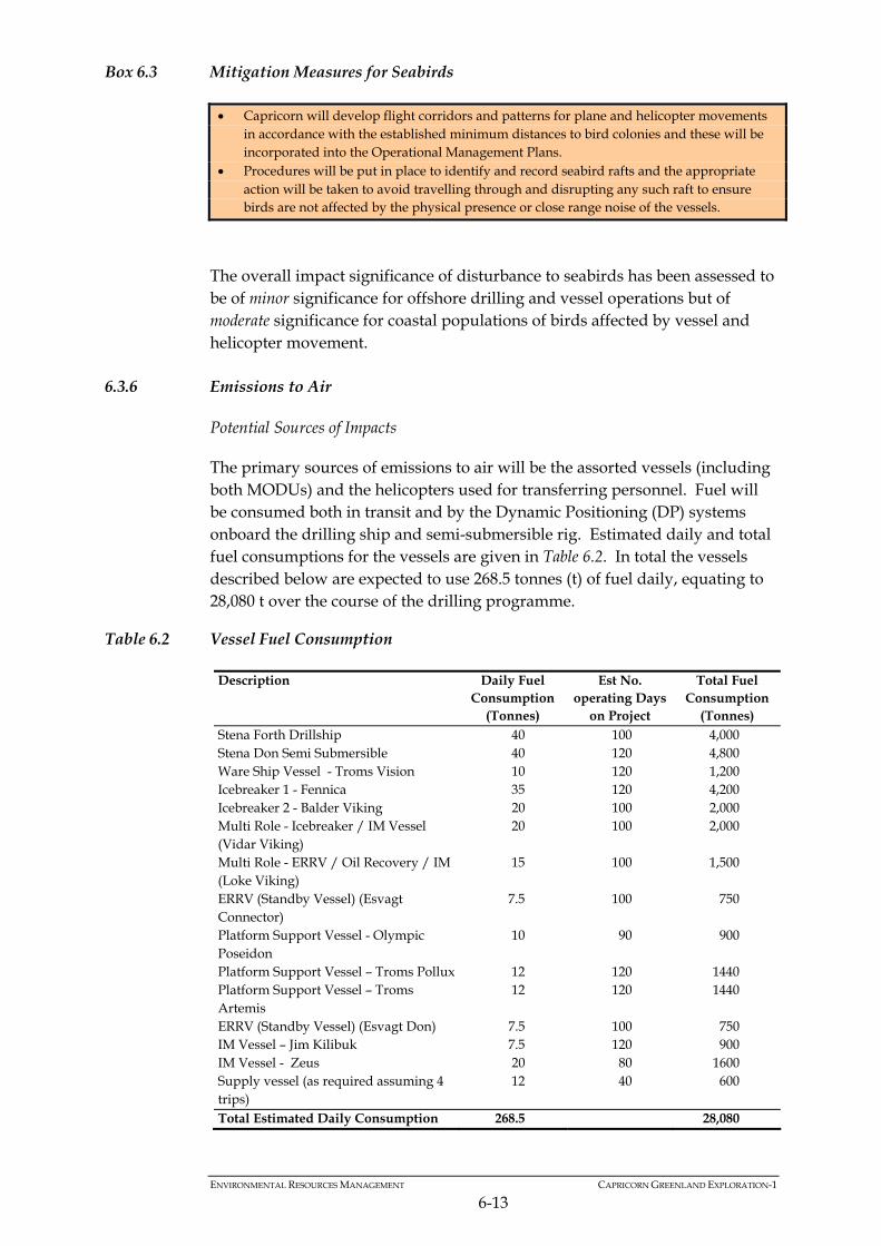
Box 6.3 Mitigation Measures for Seabirds
Capricorn will develop flight corridors and patterns for plane and helicopter movements in accordance with the established minimum distances to bird colonies and these will be incorporated into the Operational Management Plans.
Procedures will be put in place to identify and record seabird rafts and the appropriate action will be taken to avoid travelling through and disrupting any such raft to ensure birds are not affected by the physical presence or close range noise of the vessels.
The overall impact significance of disturbance to seabirds has been assessed to be of minor significance for offshore drilling and vessel operations but of moderate significance for coastal populations of birds affected by vessel and helicopter movement.
6.3.6 Emissions to Air
Potential Sources of Impacts
The primary sources of emissions to air will be the assorted vessels (including both MODUs) and the helicopters used for transferring personnel. Fuel will be consumed both in transit and by the Dynamic Positioning (DP) systems onboard the drilling ship and semi-submersible rig. Estimated daily and total fuel consumptions for the vessels are given in Table 6.2. In total the vessels described below are expected to use 268.5 tonnes (t) of fuel daily, equating to 28,080 t over the course of the drilling programme.
Table 6.2 Vessel Fuel Consumption
Description Daily Fuel Consumption
(Tonnes)
Est No. operating Days
on Project
Total Fuel Consumption
(Tonnes) Stena Forth Drillship 40 100 4,000 Stena Don Semi Submersible 40 120 4,800 Ware Ship Vessel - Troms Vision 10 120 1,200 Icebreaker 1 - Fennica 35 120 4,200 Icebreaker 2 - Balder Viking 20 100 2,000 Multi Role - Icebreaker / IM Vessel (Vidar Viking)
20 100 2,000
Multi Role - ERRV / Oil Recovery / IM (Loke Viking)
15 100 1,500
ERRV (Standby Vessel) (Esvagt Connector)
7.5 100 750
Platform Support Vessel - Olympic Poseidon
10 90 900
Platform Support Vessel – Troms Pollux 12 120 1440 Platform Support Vessel – Troms Artemis
12 120 1440
ERRV (Standby Vessel) (Esvagt Don) 7.5 100 750 IM Vessel – Jim Kilibuk 7.5 120 900 IM Vessel - Zeus 20 80 1600 Supply vessel (as required assuming 4 trips)
12 40 600
Total Estimated Daily Consumption 268.5 28,080
ENVIRONMENTAL RESOURCES MANAGEMENT CAPRICORN GREENLAND EXPLORATION-1
6-13

ENVIRONMENTAL RESOURCES MANAGEMENT CAPRICORN GREENLAND EXPLORATION-1
6-14
MODUs and support vessels will use low sulphur (≤ 1.5%) fuel. Pollutant emission figures for each vessel/rig have been calculated based on estimated tonnes of diesel fuel usage and emission factors for diesel combustion (1) (see Table 6.3). Greenhouse gas (GHG) emissions are estimated in the equivalent tonnes of CO2 (CO2E). Emissions from helicopters are not available but are likely to contribute only a small proportion of the total pollutant emissions from the Project.
Table 6.3 Air Emissions
GHG Emissions (GHG)
Description
Total Fuel Consumption (t) CH4 (t) CO2 (t) (t CO2E) NOX (t) VOCs (t) SO2 (t) N2O (t) CO (t)
Stena Forth Drillship 4,000 0.5 13,114.2 13,158.3 237.6 8.0 16.0 0.1 62.8 Stena Don Semi Submersible 4,800 0.6 15,737.1 15,789.9 285.1 9.6 19.2 0.1 75.4 Ware Ship Vessel – Troms Vision 1,200 0.2 3,934.3 3,947.5 71.3 2.4 4.8 0.0 18.8 Icebreaker 1 - Fennica 4,200 0.6 13,769.9 13,816.2 249.5 8.4 16.8 0.1 65.9 Icebreaker 2 - Balder Viking 2,000 0.3 6,557.1 6,579.1 118.8 4.0 8.0 0.1 31.4 Multi Role - Icebreaker / IM Vessel (Vidar Viking) 2,000 0.3 6,557.1 6,579.1 118.8 4.0 8.0 0.1 31.4 Multi Role - ERRV / Oil Recovery / IM (Loke Viking) 1,500 0.2 4,917.8 4,934.4 89.1 3.0 6.0 0.0 23.6 ERRV (Standby Vessel) (Esvagt Connector) 750 0.1 2,458.9 2,467.2 44.6 1.5 3.0 0.0 11.8 Platform Support Vessel – Olympic Poseidon 900 0.1 2,950.7 2,960.6 53.5 1.8 3.6 0.0 14.1 Platform Support Vessel – Troms Pollux 1,440 0.2 4,721.1 4,737.0 85.5 2.9 5.8 0.0 22.6 Platform Support Vessel – Troms Artemis 1,440 0.2 4,721.1 4,737.0 85.5 2.9 5.8 0.0 22.6 ERRV (Standby Vessel) (Esvagt Don) 750 0.1 2,458.9 2,467.2 44.6 1.5 3.0 0.0 11.8 IM Vessel – Jim Kilibuk 900 0.1 2,950.7 2,960.6 53.5 1.8 3.6 0.0 14.1 IM Vessel - 1,600 0.2 5,245.7 5,263.3 95.0 3.2 6.4 0.0 25.1
(1) Methods for estimating atmospheric emissions from E&P Operations, Report No 2.59 /197 September 1994, The oil
Industry International Exploration and Production Forum.

ENVIRONMENTAL RESOURCES MANAGEMENT CAPRICORN GREENLAND EXPLORATION-1
6-15
GHG Emissions (GHG)
Description
Total Fuel Consumption (t) CH4 (t) CO2 (t) (t CO2E) NOX (t) VOCs (t) SO2 (t) N2O (t) CO (t)
Zeus Supply vessel (as required assuming 4 trips) 600 0.1 1,967.1 1,973.7 35.6 1.2 2.4 0.0 9.4 Total Emissions 25,880 3.7 92,061.9 92,371.2 1,668.0 56.2 112.3 0.7 440.9
Notes: Data for the Stena Forth is not available, the data used is for the Stena Carron, which is the sister ship to the Stena Forth.
The emissions to air figures above are estimates based on a best guess of operations. They have been calculated using estimated fuel consumption and standard industry air emission conversion factors consistent with the reporting format for the Project (UK Environmental Emissions Monitoring System and American Petroleum Institute (2009)
Each of the crew-change helicopters (one S92 and one S61) are expected to make one return flight per day five days a week from Aasiaat to the licence area. Actual fuel consumption will vary with payload, weather, speed etc however taking an average distance to the drilling area from the onshore base as 370 km and an average fuel consumption of 0.4 km/l fuel (1) it is estimated that helicopter fuel consumption would be: 18,500 litres per week. Over the 150 day drilling period (approximately 21.4 weeks) an approximate figure of 395,900 litres of fuel may be used. There is an estimated probability of less than 10% that flaring will be required at each well. Any flaring required will be tested for approximately 48 hours over a period of five days. Flaring of hydrocarbons will result in emissions to air (predominantly of CO2). Before any flaring is carried out, a flaring consent will be applied for and issued by the BMP. Changes to Air Quality
Release of gaseous pollutant emissions to the atmosphere will adversely affect local air quality. In addition there will be a release of greenhouse gases. Pollutant emissions will be released at each of the well sites and along the route between the licence area and onshore bases. The majority of emissions will come from the ice breaking/management vessels and the drilling vessel and rig, which will operate in the Sigguk Licence Area in open sea over 100 km from the closest point of the west Greenland coast. The emissions will occur over an estimated period of 120 days. The overall duration of the Project is short term and the drill sites are in open sea with good conditions for the dispersion of pollutants and distant from sensitive receptors. Given the relative scale of the Project in relation to global past and current anthropogenic emissions the contribution to global warming will be inconsequential. Therefore the magnitude of the impact to air quality
(1) Fuel consumptions are 0.35 km/l and 0.45 km/l for the S92 and S61 respectively.

and to climate change are both rated as negligible to small and the overall impact of emissions to air is assessed as being not significant. If flaring is required it will emit emissions to the air, however, this activity will be of short duration and the following mitigation measures (Box 6.4) will reduce the potential impact to air quality. The residual impact to air quality from flaring after mitigation is assessed to be not significant.
Box 6.4 Mitigation Measures for Impacts to Air
Emissions from flaring will be monitored to ensure complete combustion. Compressed air will be used to enhance combustion as required. An oil recovery vessel with full dispersant capability will be on stand by during well test
flaring.
6.3.7 Discharges to Sea
Potential Sources of Impacts
During the drilling period various types of waste and discharge will be produced, each requiring appropriate handling and disposal. Waste and discharges to the marine environment could locally affect water quality and consequently may have impacts to marine ecology. Effluent from the following sources will be discharged: grey water (eg showers, sinks); black water (sewage); organic kitchen waste; drainage, bilge and ballast water; and drilling muds and cuttings. All waste will be handled and disposed of in accordance with the Waste Management Plan and in full compliance with relevant legislation eg MARPOL (1) requirements. Waste materials will be separated offshore into controlled (non-hazardous) and hazardous wastes, solids and liquids. Clinical waste will also be stored separately. All solid waste and will be stored onboard before transfer to shore for disposal/recycling and will therefore not impact the marine environment. Any discharges of controlled (non-hazardous) waste and liquid from the washing or rinsing of containers or equipment must meet acceptable standards before discharge. Sewage and organic kitchen material will be treated prior to discharge to meet the applicable standards (ie MARPOL). Drilling muds will be water based and will be separated from returned cuttings on the rig for re-use in the operation. Treated cuttings will be discharged to sea. Specific details on waste handling/disposal routes and procedures can be found in the Project operating procedures.
ENVIRONMENTAL RESOURCES MANAGEMENT CAPRICORN GREENLAND EXPLORATION-1
6-16
(1) The Relevant provisions are in Annex IV (Sewage) and Annex V (Garbage) to MARPOL 73/78.

ENVIRONMENTAL RESOURCES MANAGEMENT CAPRICORN GREENLAND EXPLORATION-1
6-17
Changes to Water Quality
Grey Water, Black Water and Kitchen Waste Vessel/rig specific figures for estimated black and grey water discharge can be found in Table 6.4. All figures given are approximate averages and actual figures will vary. Black water will be produced at the rate of up to 50 litres per person each day (1) giving a total estimated volume of 37,050 litres each day (assuming the very unlikely situation of each vessel/rig having on board the maximum number of persons). Assuming a further 150 litres of grey water discharge per person an estimated total of 111,150 litres will be discharged each day, based on maximum persons on board. Although estimates have been based on maximum capacity the actual personnel figures, and therefore the discharge figures, will be considerably lower.
Table 6.4 Estimated Daily Black and Grey Water Discharges
Description Est No. operating Days on Project
Max POB
Max. Black water
discharge (litres)
Max. Grey water
discharge (litres)
Stena Forth Drillship 100 180 9,000 27,000 Stena Don Semi Submersible 120 102 5,100 15,300 Ware Ship Vessel – Troms Vision 120 68 3,400 10,200 Icebreaker 1 - Fennica 120 77 3,850 11,550 Icebreaker 2 - Balder Viking 100 45 2,250 6,750 Multi Role - Icebreaker / IM Vessel (Vidar Viking)
100 31 1,550 4,650
Multi Role - ERRV / Oil Recovery / IM (Loke Viking)
100 45 2,250 6,750
ERRV (Standby Vessel) (Esvagt Connector)
100 27 1,350 4,050
Platform Support Vessel - Olympic Poseidon
90 25 1,250 3,750
Platform Support Vessel – Troms Pollux 120 23 1,150 3,450 Platform Support Vessel – Troms Artemis
120 23 1,150 3,450
ERRV (Standby Vessel) (Esvagt Don) 100 27 1,350 4,050 IM Vessel – Jim Kilibuk 120 27 1,350 4,050 IM Vessel - Zeus 80 21 1,050 3,150 Supply vessel (as required assuming 4 trips)
40 20 1,000 3,000
Total Estimated Daily Figure 741 37,050 111,150
NB. Where exact vessel specification is not available (unnamed vessels) max POB has been estimated based on similar vessels.
Black water can contain harmful microorganisms, nutrients, suspended solids, organic material with a chemical and biological oxygen demand (BOD) and residual chlorine from the sewage treatment disinfection. Onboard treatment in a certificated IMO compliant sewage treatment facility will treat sewage to IMO standards as set out in Annex IV of MARPOL. The treatment standard is
(1) Based on UK domestic water use data from Water Wise
http://www.waterwise.org.uk/reducing_water_wastage_in_the_uk/
ENVIRONMENTAL RESOURCES MANAGEMENT CAPRICORN GREENLAND EXPLORATION-1
6-18
250 faecal coliforms per 100 ml, the total suspended solids must be less than 50 mg/l and the BOD less than 50 mg/l. Increased BOD directly impacts water quality by increasing the uptake of dissolved oxygen concentration by microorganisms that decompose organic material in the sewage, which in turn reduces the dissolved oxygen content of the water. Multiple drilling locations over a period of 120 days will spread the treated black water discharge over a large offshore area in relatively small volumes, which is expected to disperse and dilute quickly due to tidal currents. The magnitude of impact of the water quality due to sewage discharge is small. Adverse effects are not anticipated. Grey water discharge includes drainage from baths, showers, laundry, wash basins and dishwater. Grey water is not required to be treated before discharge by the regulations in MARPOL 73/78 as it is not considered garbage or sewage (provided it does not contain a pollutant prescribed in the Regulations or MARPOL). Therefore it may be discharged to the sea without treatment. Grey water will be discharged over a large area (mostly offshore within the Sigguk Licence Area but no closer than 100 km to the coast) over a period of 120 days and is not predicted to cause deterioration to water quality except locally to the discharge. The magnitude of this discharge is considered small. Harm to marine organisms due to grey water discharge is therefore not predicted. Organic waste discharge from galleys will introduce nutrients and organic material to the water column, which may cause a local increase in BOD. The ground (macerated) discharge will disperse and dilute quickly due to tidal currents and will be released from several vessels over a large offshore area over approximately 120 days. The magnitude of impact to water quality from organic waste discharge is rated as small. The sensitivity of the water column has been categorised as low. The overall impact of grey and black water discharges and organic kitchen waste discharge is assessed as minor. Drainage, Bilge and Ballast Water Drainage and bilge water will potentially be contaminated with oil/hydrocarbons, which would reduce water quality if discharged to the marine environment. Drainage and bilge water will be directed to the holding tank (bilges) then routed through an oil/water separator and monitored for oil concentration before discharge. The content of oil contaminated bilge water is controlled under MARPOL Annex 1 and discharge of water with greater than 100 ppm is prohibited. Discharge of such oily water is only permitted if the vessel is underway. Thus whilst drilling, discharge of oil contaminated bilge water will be prohibited. Other vessels may discharge bilge water in compliance with MARPOL Annex 1. It is expected that discharges will not exceed 15 ppm oil in water content, which will localise any impact to the vicinity of the discharge point. As the oil in water content will be below 15 ppm, there will be no visible sheen
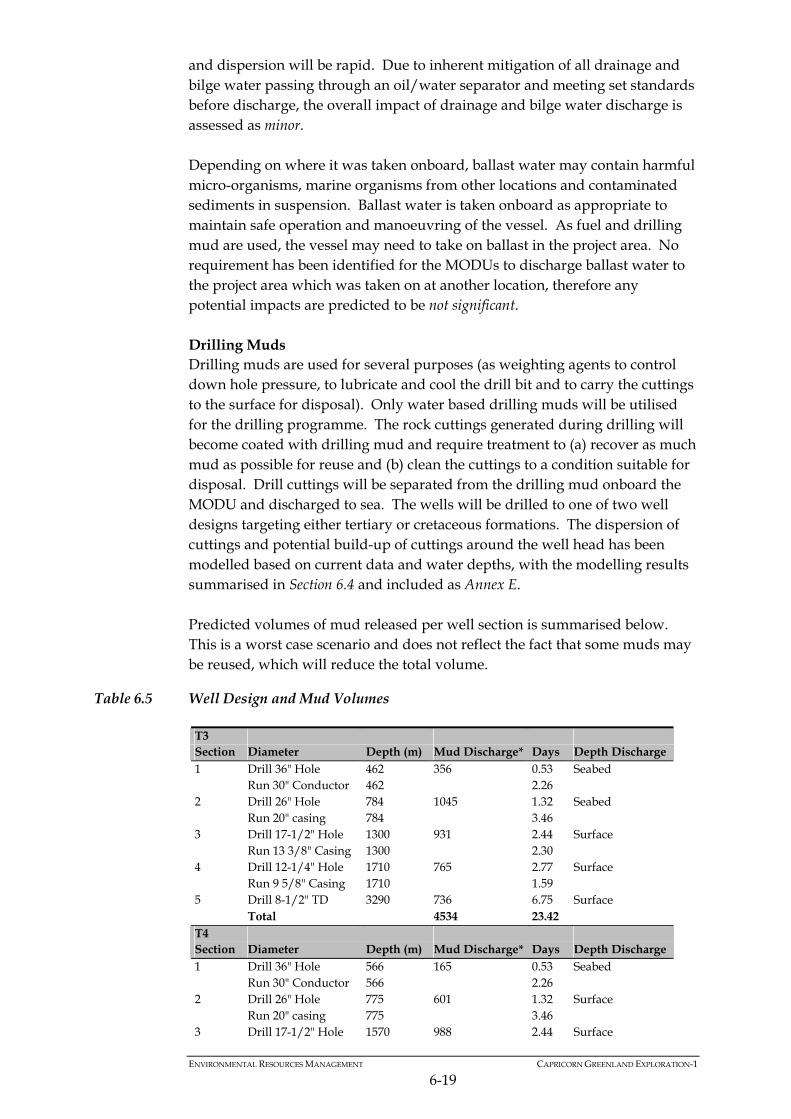
ENVIRONMENTAL RESOURCES MANAGEMENT CAPRICORN GREENLAND EXPLORATION-1
6-19
and dispersion will be rapid. Due to inherent mitigation of all drainage and bilge water passing through an oil/water separator and meeting set standards before discharge, the overall impact of drainage and bilge water discharge is assessed as minor. Depending on where it was taken onboard, ballast water may contain harmful micro-organisms, marine organisms from other locations and contaminated sediments in suspension. Ballast water is taken onboard as appropriate to maintain safe operation and manoeuvring of the vessel. As fuel and drilling mud are used, the vessel may need to take on ballast in the project area. No requirement has been identified for the MODUs to discharge ballast water to the project area which was taken on at another location, therefore any potential impacts are predicted to be not significant. Drilling Muds Drilling muds are used for several purposes (as weighting agents to control down hole pressure, to lubricate and cool the drill bit and to carry the cuttings to the surface for disposal). Only water based drilling muds will be utilised for the drilling programme. The rock cuttings generated during drilling will become coated with drilling mud and require treatment to (a) recover as much mud as possible for reuse and (b) clean the cuttings to a condition suitable for disposal. Drill cuttings will be separated from the drilling mud onboard the MODU and discharged to sea. The wells will be drilled to one of two well designs targeting either tertiary or cretaceous formations. The dispersion of cuttings and potential build-up of cuttings around the well head has been modelled based on current data and water depths, with the modelling results summarised in Section 6.4 and included as Annex E. Predicted volumes of mud released per well section is summarised below. This is a worst case scenario and does not reflect the fact that some muds may be reused, which will reduce the total volume.
Table 6.5 Well Design and Mud Volumes
T3 Section Diameter Depth (m) Mud Discharge* Days Depth Discharge 1 Drill 36" Hole 462 356 0.53 Seabed Run 30" Conductor 462 2.26 2 Drill 26" Hole 784 1045 1.32 Seabed Run 20" casing 784 3.46 3 Drill 17-1/2" Hole 1300 931 2.44 Surface Run 13 3/8" Casing 1300 2.30 4 Drill 12-1/4" Hole 1710 765 2.77 Surface Run 9 5/8" Casing 1710 1.59 5 Drill 8-1/2" TD 3290 736 6.75 Surface Total 4534 23.42 T4 Section Diameter Depth (m) Mud Discharge* Days Depth Discharge 1 Drill 36" Hole 566 165 0.53 Seabed Run 30" Conductor 566 2.26 2 Drill 26" Hole 775 601 1.32 Surface Run 20" casing 775 3.46 3 Drill 17-1/2" Hole 1570 988 2.44 Surface

ENVIRONMENTAL RESOURCES MANAGEMENT CAPRICORN GREENLAND EXPLORATION-1
6-20
Run 13 3/8" Casing 1570 2.30 4 Drill 8-1/2" TD 2400 733 5.36 Surface Total 3557 17.67 T16 Section Diameter Depth (m) Mud Discharge* Days Depth Discharge 1 Drill 36" hole 697 165 0.52 Seabed Run 30" conductor 697 2.26 2 26" Hole 825 601 1.23 Surface 20" Casing 825 3.50 3 17 1/2" Hole 1280 988 2.06 Surface 13 3/8" Casing 1280 2.26 4 8.5" Hole 2100 733 5.43 Surface Total 3557 17.25 T23 Section Diameter Depth (m) Mud Discharge* Days Depth Discharge 1 Drill 36" hole 506 165 0.39 Seabed Run 30" conductor 506 2.26 2 26" Hole 865 601 1.69 Surface 20" Casing 865 3.51 3 17 1/2" Hole 1450 988 2.34 Surface 13 3/8" Casing 1450 2.33 4 8.5" Hole 2800 733 5.45 Surface Total 3557 17.96
*Assumes total discharge as a worst case
During the drilling of sections 1 and 2, drilling fluids and cuttings will be discharged directly at the seabed as is standard practice. Sections 3, 4 and 5 of the well will see the muds being reused, although some residual mud will be discharged along with the cuttings. On completing a well the drilling rig or drillship will move to the next well location. For operational safety reasons the MODUs may need to dispose of the mud. The alternatives for disposal are: • discharge to sea; or • ‘skip and ship’ to land. The drilling fluids are of negligible to low toxicity in the marine environment and their disposal results in short-term impacts to water quality (see below). Some coarser material will reach the seabed but will not lead to the smothering impacts caused by drill cuttings disposal. In contrast, disposal to land would require specialist equipment and land take as well as presenting a long-term liability. Disposal of used whole water-based mud to sea is therefore the preferred solution. It is worth noting that National Energy Board Office Canada-Newfoundland, Offshore Petroleum Board Canada - Nova Scotia in Offshore Waste Treatment Guidelines (August 2002, ISBN 0-921569-40-8) envisage whole surplus mud disposal to sea:
ENVIRONMENTAL RESOURCES MANAGEMENT CAPRICORN GREENLAND EXPLORATION-1
6-21
“Spent and excess water-based drilling muds may be discharged onsite from offshore installations without treatment. Operators should, however, develop procedures that reduce the need for the bulk disposal of these muds following either a drilling mud changeover or a drilling program completion.” Discharging water based muds to the marine environment could potentially impact water quality in two ways: pollution from chemicals in the muds; and/or increased turbidity. Water based muds, which are primarily made up of water (approximately 75% freshwater, seawater or brine) with some added inert chemicals such as barite and clays/polymers will be used for all drilling in the Sigguk licence area. The drilling fluid chemicals to be utilised by the Project will conform to OSPAR HOCNF and CHARM as well as being classified as substances that Pose Little Or No Risk to the environment (PLONOR chemicals) under Annex 6 of the OSPAR convention, unless there is an overriding case for using a non-PLONOR chemical (ie there is none available for the specific task). Water based muds are considered to be essentially non-toxic and the effect on marine life is considered slight to none when drill cuttings are discharged overboard. They also do not bioaccumulate. The magnitude of impact caused by the chemical content of the water based muds on the water quality is regarded as small. Discharge of water based muds and cuttings at the sea bed will cause local increases in turbidity near to the seabed, while discharges at the sea surface will be suspended in sea water creating a discharge ‘plume’ of finer material released from the coarser cuttings that drift with prevailing currents. Rapid dilution and dispersion of the discharge ‘plume’ is expected due to tidal currents and the water depths in the Sigguk block (>300 m). Dilution of the ‘plume’ in well-mixed ocean waters, is estimated to be 100-fold within 10 m of the discharge and 1,000-fold after 10 minutes approximately 100 m from the platform (depending on the current speed) (1). The magnitude of increased turbidity in the water column due to discharged drilling muds is considered small. Whilst drilling the reservoir it is possible that hydrocarbons may be released into the cuttings discharge from oil bearing rock. The oiled cuttings will be returned to the rig for treatment prior to disposal. If on-board treatment cannot reduce the proportion of oil on cuttings to a level agreed with the Greenland authorities, they will be contained and transported for treatment or disposal at a suitable facility outside of Greenland.
(1) Neff, J.M. (2005) Composition, environmental fates and biological effects of Water based drilling muds and Cuttings discharged to the marine environment: A Synthesis and Annotated Bibliography Prepared for Petroleum Environmental
Research Forum (PERF) and American Petroleum Institute.

ENVIRONMENTAL RESOURCES MANAGEMENT CAPRICORN GREENLAND EXPLORATION-1
6-22
At the end of drilling there will be a one off discharge event of water based muds. Any ‘plume’ created from the discharge of drilling muds to the water column will likely dilute and disperse quickly with no lasting effects. The sensitivity of the water column has been categorised as low. The magnitude of impact from both additives in the mud and increased turbidity has been judged to be small. The overall impact of drilling muds discharged to the water column will be of minor significance. Harm to pelagic species is unlikely and has not previously been demonstrated (1). The impacts of water based mud and cutting discharge are primarily physical (with potential secondary effects to seabed fauna) as they will form a footprint on the seabed and have been assessed separately in Section 6.3.8. All liquid discharges will affect the salinity and potentially the temperature of the local area. However, due to tidal currents diluting and dispersing the effluent the local changes are expected to be minor and will not impact the marine environment. Secondary Impacts to Marine Fauna
Increased nutrients in the water column due to discharge of organic waste may increase the local productivity of phytoplankton (primary production), however, any changes in productivity are expected to be short lived as discharges will be rapidly diluted in the water column. Increased turbidity to the water column could potentially affect local levels of primary production through a reduction in light. However, it has been shown that given rapid dilution of water based drilling muds, phytoplankton composition or productivity is not significantly affected relative to natural variation (2). Due to high levels of natural variation, impacts to phytoplankton caused by changes in water quality are therefore not expected to be measurable. Benthic organisms may be affected by increased turbidity, which can cause irritation to the benthos and affect their growth and feeding. Some species are more sensitive to increased turbidity than others. As increased turbidity is local and temporary the magnitude of impact to the benthos is very small. Their importance is rated as low. The overall impact of changes in water quality due to discharges to benthic organisms is not significant. Impacts to benthos due to smothering caused by drilling muds discharge is assessed in Section 6.3.8.
(1) Neff, J.M. (2005) Composition, environmental fates and biological effects of Water based drilling muds and Cuttings
discharged to the marine environment: A Synthesis and Annotated Bibliography Prepared for Petroleum Environmental Research Forum (PERF) and American Petroleum Institute.
(2) Alldredge, AL., Eliasa, M. and Gotschalk, CC. (1986) Effects of drilling muds and mud additives on the primary production of natural assemblages of marine phytoplankton Marine Environmental Research. Volume 19, Issue 2, 157-
176pp.

Temporary distribution changes may also be caused by opportunistic feeders being attracted to organic kitchen waste discharge as a food source. The magnitude of changes on this scale is small in comparison to the natural variability in fish distribution. Fish have been categorised as of medium importance. The overall impact to fish caused by changes in the water column is minor. A population of marine mammals is most likely to be affected if their foraging or migration is interrupted or if they are disturbed during their breeding period. Many marine mammal species utilise fish as a food source and may be impacted by changes in fish distribution. However, secondary impacts up the food chain will not occur. The impact to marine mammals due to changes in the water column is assessed to be not significant.
Box 6.5 Summary of Impacts to Marine Fauna
Box 6.6 Mitigation Measures for Impacts to Water Quality
Major impacts to marine fauna are not anticipated due to the generally low toxicity of the drilling mud additives, non persistent nature of the effluent discharged and high dispersion in the open sea of the project site. Impacts to phytoplankton have been rated as not significant. Impacts to benthic species have been rated as not significant and fish have been rated as minor. Impacts to marine mammals have been rated as not significant.
Use of water based muds. Selection of low toxicity mud formulations Mud control to reduce the amount of mud released to the water column Monitoring of hydrocarbons in reservoir cuttings Contingency arrangements for hydrocarbon contaminated cuttings
6.3.8 Seabed Impacts
Potential Sources of Impacts
The potential sources of impact on the seabed are as follows: direct habitat destruction due to placement of seabed structures; smothering of benthos; toxic effects due to drilling mud additives; and changes in sediment chemistry and particle size distribution. Potential Impacts to the Seabed
The exploration drilling activity will have minimal seabed footprint from placement of structures as the drilling units will be dynamically positioned and will not require anchoring. The only footprint in this regard will be the well itself. Top-hole cuttings, treated drill cuttings and any overspill cement released to the seabed will, however, form a footprint on the seabed around
ENVIRONMENTAL RESOURCES MANAGEMENT CAPRICORN GREENLAND EXPLORATION-1
6-23
ENVIRONMENTAL RESOURCES MANAGEMENT CAPRICORN GREENLAND EXPLORATION-1
6-24
the wellhead. This will result in physical damage and habitat loss / disruption over a defined area of the seabed. Cement will be used to secure the wellheads. A small proportion of cement will reach the environment. Any leaching into the seawater will be such a slow process that non-sediment dwelling organisms will not be at significant risk to exposure to concentrations above respective thresholds. Cement discharged to the seabed will be at the centre of the cuttings pile from the riserless sections of the well (top hole). Cuttings from the top hole will be released directly onto the seabed and will smother sessile fauna within the footprint of the cuttings. The primary drilling fluid for the riserless sections of the well will be seawater and inert natural products (such as bentonite) that are of inherent low toxicity to marine life. Reactivity and dissolution of chemicals into seawater will be limited. Once the riser is in place, cuttings will be returned to the drilling unit, separated from the drilling muds and discharged through a pipe near the sea surface. Cuttings dispersion modelling has been undertaken by Applied Science Associates Ltd (ASA) for four representative well locations to give a full field plot of the maximum area to be affected by cuttings to the 1 mm depth of deposition contour. Four potential well locations (including Alpha and T4) were selected for the cuttings dispersion modelling, with modelling at two of the potential well locations considered unnecessary due to the similarities in position, depth and current profile with other nearby locations. For all locations modelled the predicted bottom deposition greater than 1 mm extends less than 200 m from the drill site in any direction, and is primarily due to the discharged cuttings which remain in the vicinity due to their faster settling rates. Deposits greater than 1 mm in thickness will cover an area of approximately 0.13 km2 at the Alpha well, 0.08 km2 at the T4 and T16 wells, and 0.09 km2 at the T8 well (Gamma). Very low levels (0.01 mm) of deposition are predicted further out from the well sites but deposition at this level is not considered environmentally relevant (see Figure 6.2).

SIZE:
TITLE:
DATE: 08/06/2010
DRAWN: CJ
CHECKED: RB
APPROVED: JP
PROJECT: 0108885
SCALE: As scale barsDRAWING: REV:
KEY:
A3
Figure 6.2Combined Mud and Cuttings Deposition at Alpha, T8 (Gamma), T4 and T16 Proposed Well Site Locations
6.2_DrillingMuds.mxd 0
Sigguk Licence AreaBottom Thickness (mm)
0.010.01 - 0.020.02 - 0.050.05 - 0.10.1 - 0.20.2 - 0.50.5 - 11 - 22 - 55 - 1010 - 20
CLIENT:Capricorn Greenland Exploration-1
T16
T8
T4
Alpha
File:
0108
885G
reenla
ndW
estG
IS_C
J_JP
\Map
s\Well
3 an
d 4\6.
2_Dr
illingM
uds.m
xd
ERMEaton HouseWallbrook CourtNorth Hinksey LaneOxford OX2 0QSTelephone: 01865 384800Facsimile: 01865 204982
© ERM This print is confidential and is supplied on the understanding that it will be used only as a record to identify or inspect parts, concepts or designs and that it is not disclosed to other persons or to be used for construction purposes without permission.
SOURCE: ASAPROJECTION: WGS 1984 UTM Zone 21N
.0 1
Kilometers
0 10050Kilometers

ENVIRONMENTAL RESOURCES MANAGEMENT CAPRICORN GREENLAND EXPLORATION-1
6-26
The drilling mud additives will be of generally low toxicity as discussed in Section 6.3.7. On board treatment of cuttings as described in Section 6.3.7 will reduce the proportion of the mud co-discharged with the cuttings. It is possible that small amounts of petroleum products may be associated with the cuttings drilled through the oil containing formations. If on board treatment cannot reduce the proportion of oil on cuttings to a level agreed with the Greenland authorities, they will be contained and transported for treatment or disposal at a suitable facility. A specialist waste management contactor will be used to transport any oiled cuttings and all necessary transfer notes and permits will be obtained and held. Studies on water based mud cuttings piles which have been contaminated with hydrocarbons from drilling through geological strata indicate that levels are generally below the threshold for causing effects in benthos ie 50 to 60 mg/kg (1). Studies of water based mud cuttings piles demonstrate that effects are related to the amount of cuttings discharged and the extent to which they accumulate. The mechanism of impact is by burial and a reduction in sediment reduction-oxidation (redox) potential (the amount of oxygen in the sediment) due to the oxidation and microbial degradation of biologically degradable chemicals in the mud. Unused mud will be disposed of at the surface in such a way as to encourage dispersion in the water column entraining the muds in a seawater flow at the surface. The seabed at the well sites is not subject to strong currents or wave action so erosion of the cuttings pile would be slow; however both T3 and T4 are subject to slight ice scour periodically which may cause erosion of the cuttings pile. The benthos of the well sites is typical of circumpolar waters of this depth and reflects the relative stability of the ocean floor. In areas subject to high levels of deposition mortality of sedentary species will result as they will be unable to migrate upwards through the cuttings deposit. The cuttings pile surface will be colonised by opportunistic species able to tolerate disturbance and the reduced redox potential, which are likely to colonise the area quickly. Typically the opportunists would comprise large numbers of a few species which are small and have relatively short life spans. Once the well has been completed and deposition of cuttings stopped, larger longer-lived species will recolonise the area during the seasonal spat fall. This sequence would be similar to the recovery of a location affected by ice scour. The area over which effects on fauna are anticipated is predicted to be small, less than 0.05 km2 for both wells based on the 5 mm deposition contour.
(1) Neff, J. M., 2005. Composition, environmental fates, and biological effects of water based drilling muds and cuttings discharged to the marine environment: A synthesis and annotated bibliography. Prepared for Petroleum Environmental Research Forum
(PERF) and American Petroleum Institute.

Ultimately the cuttings piles would be similar to surrounding areas in terms of their benthic communities but it is likely there would be some differences due to the different physical and chemical characteristics of the sediment on the pile resulting in a different ‘climax community’. Recovery to a stable community would likely take one to two seasons. In summary the effects of the cuttings deposition on the seabed will be to change the benthic communities over a small area for a short period of time. Sediment chemistry and particle size would be changed for a longer period within the footprint of the cuttings deposition. The drilling mud additives are low toxicity and will not bio-accumulate. The overall impact from drill cuttings to the seabed and associated benthic communities is assessed to be minor. Provided the dispersion of waste mud is encouraged it will not accumulate on the seabed and resultant effects will be negligible. After well suspension and abandonment, recolonisation of the area by benthic fauna will commence. The cement chemicals to be utilised by the Project will be used downhole and will conform to OSPAR HOCNF standards and Danish chemical registration systems. Any leaching of chemicals from the cement will be released at levels not toxic to the environment. The area of seabed affected will be very small and significance is predicted to have no impact.
Box 6.7 Mitigation Measures for Impacts to the Seabed
Selection of low toxicity mud formulations. Mud control reduce amount of mud discharged to water column. Monitoring of hydrocarbons in reservoir cuttings. Contingency arrangements for hydrocarbon contaminated cuttings. Dissipative disposal of unused mud.
6.4 IMPACTS FROM UNPLANNED EVENTS
6.4.1 Introduction
This section addresses the potential for accidental oil spill events, chemical spills and unexpected loss of materials associated with the proposed drilling activity, their likelihood of occurrence and the potential impacts on environmental resources and receptors should they occur. The measures that will be established to prevent unplanned events and to respond to any such events that do occur are summarised in the Environmental Management and Mitigation Chapter. Full details of the procedures in place to respond to oil spills during the drilling campaign are provided in the project specific Oil Spill Response Plan. For the present project the main potential source of accidental impact to the environment would be in the event of an oil spill.
ENVIRONMENTAL RESOURCES MANAGEMENT CAPRICORN GREENLAND EXPLORATION-1
6-27

ENVIRONMENTAL RESOURCES MANAGEMENT CAPRICORN GREENLAND EXPLORATION-1
6-28
Oil spill scenarios were considered for the development based on historical information and the project description. Scenarios where chosen for further study where they could provide insight into the potential for environmental harm to important receptors in the project area. Oil spill modelling was undertaken to inform the assessment as detailed in Section 6.4.2 with full details provided in Annex E. Various hazardous materials will be stored and used in bulk (eg in containers or systems with greater than 1 m3 capacity) during construction and operation. The most important of these are listed below: diesel; heavy fuel oil; lubricating oils; hydraulic oils; and aviation fuel. Spills of crude oil from the geological reservoir, diesel and heavy fuel oil were considered the most significant due to their presence offshore in potentially large quantities and potential effects. Data from the International Association of Oil and Gas Producers indicate that for all oil and gas operating areas of the world small spills (<10 bbl or 1.6 m3) are the most common with the size of the spill being inversely related to likelihood (1). The potential for major environmental harm is dependent on the context and location of the spill but is closely related to the size. In the context of this development most small spills could occur on vessels in areas where fuel is handled. These areas will be bunded onshore and on the MODUs and vessels and therefore spilled oil would have little probability of reaching the sea. The impacts of small spills are correspondingly of lesser potential significance, therefore this assessment concentrates on medium and larger spills, which as stated earlier are much less likely to occur. The main risk of a large spill during exploration drilling is either a vessel collision or a loss of well control in combination with encountering a hydrocarbon reservoir containing oil at pressure greater than the hydrostatic head of the overlying water column. These two scenarios have therefore been selected for further consideration to assess the likelihood of the incident occurring, modelling of oil spill fate and the vulnerability and sensitivity of the resources which may be affected.
(1) OGP, 2009. Environmental performance in the E and P Industry 2008 data. Available from:
<http://www.ogp.org.uk/pubs/429.pdf>
ENVIRONMENTAL RESOURCES MANAGEMENT CAPRICORN GREENLAND EXPLORATION-1
6-29
6.4.2 Oil Spill Modelling
The approach methods and results of the oil spill modelling are explained fully in Annex E. Oil spill modelling for drilling operations in the Sigguk Licence Area was conducted based on well locations Alpha and T4. This provided simulations covering both the northern and southern parts of the Licence Area to encompass any current variations across the block, while also providing models for the worst case (ie closest to land) scenario. Taken together, the results from both sites demonstrate the range of oil spill simulations from operations in the Licence Area and both sets of models are included within the Annex. Assessment of Sensitivity and Vulnerability
For the purposes of this assessment, sensitivity is defined as the potential of an oil spill to cause serious harm or damage to a receptor or resource. This will depend on a number of factors such as: the tendency for the receptor to recover; the effect on the receptor of exposure to oil (eg death or serious impairment
of species); the life stage of an organism; and the season with relation to presence or absence of receptors. Vulnerability in this report refers to the tendency of the receptor to be exposed to oil which is present in the immediate vicinity. Thus there will be a physical pathway by which the oil can reach the receptor. This is a combination of proximity to contaminated seawater which is dependent on the dispersion and physical behaviour of the oil and the seasonal presence or absence of the receptor. Receptors for which there is no clear or consistent pathway by which they may be affected by an oil spill are not considered vulnerable. For example there may be very sensitive habitats which are above the high tide line and therefore not reached by beached oil. The sensitivity and vulnerability of major animal groups and habitats which are at risk from an oil spill in the project area are discussed in Annex E.
6.4.3 Scenarios Modelled
No precise information is available on the type of oil likely to be encountered during drilling. A typical medium crude with a high tendency to emulsify was therefore chosen to base the oil spill modelling on to represent a reasonable worst case. The characteristics of the oil types under consideration are summarised in Table 6.6 below.
Table 6.6 Characteristics of oil types modelled
Oil Type Density (g/cm3) Viscosity (cP) Surface Tension
(dyne/cm)
Maximum Water
Content % Medium Crude 0.8373 33.0 30.0 70

ENVIRONMENTAL RESOURCES MANAGEMENT CAPRICORN GREENLAND EXPLORATION-1
6-30
Oil Type Density (g/cm3) Viscosity (cP) Surface Tension
(dyne/cm)
Maximum Water
Content % Diesel Fuel 0.8310 2.8 27.5 0 Heavy Fuel Oil 0.9275 17.0 30.2 60
At each site three potential spill scenarios were considered: a blowout of medium crude oil; a maximum release of diesel oil; and a maximum release of heavy fuel oil. All spill scenarios were simulated during the drilling period, June to September (and beyond), corresponding to the ice-free period within which operations can be undertaken. Due to the specified drilling window, ice cover or oil and ice interaction were not considered in these simulations and sufficient time is anticipated to be available for a relief well prior to return of the ice. Water temperatures were held constant at 5°C. The diesel and heavy fuel oil simulations were run for seven days. The medium crude simulations were run for a total of 60 days. Crude simulations were based on a 5,000 barrel per day release rate (approx. 795 m3) lasting 37 days. The scenarios are summarised below in Table 6.7.
Table 6.7 Summary of Stochastic Modelling Scenarios
Scenario Location Oil Type Total Release Volume (m3)
Release period
1 Alpha Medium Crude 29,413 37 days 2 Alpha Diesel 11,500 1 hour 3 Alpha Heavy Fuel Oil 1,690 1 hour 4 T4 Medium Crude 29,413 37 days 5 T4 Diesel Fuel 11,500 1 hour 6 T4 Heavy Fuel Oil 1,690 1 hour
The behaviour of oil when released to water is discussed below. Behaviour of Oil in Water
Following release of oil into water, a number of processes occur which affect the fate of the resulting slick. These processes are affected by the chemical and physical properties of the oil such as its density, chemical composition (eg relative proportions of different hydrocarbons), viscosity, flash point etc. The most important processes to affect oil following a spill are dispersion and weathering. These processes are described in more detail below. The principal mechanisms of dispersion are as follows. Spreading – tendency to spread on the water surface. This is primarily a
function of the viscosity of the oil and is affected by temperature. Drift – the effect of tidal currents and wind. Oil will drift at the speed and
direction of the tidal current but will be affected by approximately 3% of the wind speed. These two factors will combine to give a drift vector.

Weathering is a complex series of physical, chemical and biological processes by which the volume of the oil on the water surface reduces. The principal mechanisms involved in weathering are as follows and the potential impacts of these are illustrated in Figure 6.3.
Evaporation – loss of light, low molecular weight fractions. Emulsification – combination with water to form oil-in-water emulsion. Dispersion - breaking up of the slick into small droplets which combine
with suspended particles and allow the oil to be dispersed in the water column and ultimately to sink to the seabed.
Oxidation – chemical/biological processes which break down the oil. The relative importance of these mechanisms is determined by the characteristics of the oil and the ambient conditions.
Figure 6.3 Potential Ecological Impacts of Oil Spills
Low temperatures and presence of ice affects the behaviour of oil that has been released. Although oil in ice has not been modelled it is worth briefly considering some of the potential effects. Oil may be deposited on top of the ice, encapsulated within it or it may collect in pools underneath the ice surface. As the condition of the ice changes so the fate of oil which has been spilt will also change. It has been reported that oil trapped under ice weathers at 10-20% of the rate it would at the open sea surface whilst encapsulated oil hardly weathers at all. Oil trapped within or underneath ice can travel much further than in ice free waters and may migrate to the surface of the ice or open leads as they form. More detail of the processes which affect the behaviour of oil spills in ice affected waters are given in Box 6.8 below.
ENVIRONMENTAL RESOURCES MANAGEMENT CAPRICORN GREENLAND EXPLORATION-1
6-31

Box 6.8 Behaviour of Oil Spilt in Sea Ice
When an oil spill comes into contact with ice there are a number of processes which may occur, affecting the rate of weathering and spread of the oil.
Oil spilt under conditions where sea ice is forming may remain on top of the ice as it forms beneath it but generally under these circumstances it will become encapsulated within the ice.
Oil at the ice/water interface can migrate to the underside of the ice where, given sufficient current velocity (eg 0.04 m s-1 for diesel) it can travel with the current collecting in pockets or behind ridges on the underside of the ice. Here its fate will be affected by the shape and characteristic of the ice. Trapped oil may reach the surface in leads or holes in the ice surface or it may become encapsulated in the ice.
New ice is formed at the ice/seawater boundary and so oil on the underside of an ice flow can become trapped within the body of the ice and travel vertically as the surface is eroded by melting and new ice forms below it. By this mechanism oil can be deposited on the surface of the ice or it can be released later when the ice melts. Ice, particularly old or melting ice, is porous and so can absorb oil.
Unless the ice is shore-fast it will move with water and wind currents. As it does so irregularities such as pressure ridges and rouble fields will form and oil will tend to concentrate in void spaces created by the structure of the ice.
6.4.4 Baseline Wind and Tide Conditions
The baseline wind and tidal conditions are described in Section 4.1.
6.4.5 Sensitive Features
The following features are sensitive to oil spills as detailed in Annex E. Coastal Habitat - Soft Sediment Shores
Soft sediment shores increase in their sensitivity to oil spills depending on the degree of exposure to wave and current energy. Sheltered mud flats and salt marshes are the most sensitive and take longest to recover. Coastal Habitat - Rocky and Boulder Shores
Hard substrata shores are generally less sensitive than soft sediment shores but again the effects and recovery of the spill will depend on the degree of exposure to wave and tidal action. Coastal Habitat - Sublittoral Habitats
Sublittoral soft sediment habitats in shallow waters may be affected by dispersed oil and oil which has become associated with fine sediment. Diesel spills are likely to affect animal species in the shallow sublittoral, particularly nearer the coasts where wave action will increase dispersion into the water column. Contaminated sediment may ultimately sink to areas of the seabed where it has the potential to accumulate.
ENVIRONMENTAL RESOURCES MANAGEMENT CAPRICORN GREENLAND EXPLORATION-1
6-32

ENVIRONMENTAL RESOURCES MANAGEMENT CAPRICORN GREENLAND EXPLORATION-1
6-33
Birds
Sea birds (ie auks, gulls and water fowl) are highly sensitive to oil spills because of their potential exposure to oil on the water surface and tendency to congregate in high density aggregations during critical periods eg breeding and migration. The oil principally affects birds by removal of the natural buoyancy and thermal insulating properties of the feathers and by ingestion during feeding and grooming. Birds that forage at sea are sensitive to oil exposure. This could be particularly damaging to the population during the breeding season when parent birds are feeding unfledged young and subsequently for moulting young. The species most likely to be affected by a spill depends on the circumstances of the incident eg the time of year, location, size and type of oil and type of habitat affected. Severe events can be harmful at the population level (1). Williams et al (1995) (2) proposed a method for assessment of seabird vulnerability to surface pollutants which used the following factors to generate a vulnerability score for the UK coastal waters and the North Sea. Proportion of each species that was oiled of those found dead on the
shoreline and the proportion of the time spent on the surface of the sea by that species (based on UK survey data).
Bio-geographical population. Potential rate of recovery following a reduction in numbers. Reliance on the marine environment. This approach provides a useful insight into the potential effects of oil spills on sea birds in the study area and is used below to indicate the general vulnerability of the main types (auks, gulls and water fowl) of seabirds. Auks and divers are generally the most sensitive species due to their reliance on the open sea habitat and their low potential for recovery followed by gulls and then water fowl. More detail is provided in Annex E. Sea Mammals - Pinnipeds
The following causes of harm to seals from oil have been identified based on Engelhardt (1983) (3):
(1) Piatt, J. F., Carter, H. R. & Nettleship D. N. 1990. Effects of Oil Pollution on Marine Bird Populations. Proceedings from: the Oil Symposium Herndon, Virginia October 16-18, 1990. (2) Willians, J. M., Tasker, M. L., Carter, I. C. & Webb, A. 1995. A method of assessing seabird vulnerability to surface pollution. IBIS, 137:147-152. (3) Englehardt, F.R. 1985. Petroleum Effects on Marine Mammals. Aquatic Toxicology, 4:199-217

ENVIRONMENTAL RESOURCES MANAGEMENT CAPRICORN GREENLAND EXPLORATION-1
6-34
damage to sensitive tissue through direct contact with lungs following inhalation or eyes through direct contact;
toxic effects following ingestion; effects on thermoregulation; impairment of locomotion in viscous oil; and behavioural modifications due to avoidance. Seals are not highly sensitive to oil contamination as they do not rely on their fur for insulation, do not groom themselves and do not tend therefore to take up hydrocarbon residues. The vulnerability of pinnipeds will depend on the following factors. Habitat. Physical contact with oil will be greater where the spill affects the
coast or ice used by seals to breed or haul out. Species which spend proportionately more of their time hauled out will have a greater exposure to oil than those which spend a greater proportion at sea. Oil spilt amongst ice is likely to take longer to weather, may be encapsulated and concentrated in leads or breathing holes. Consequently seals which use ice for breeding and hauling out are more vulnerable than those which do not.
Gregariousness. Potentially a larger proportion of a population could be
affected if a spill contaminates locations where gregarious species congregate.
Feeding habit. Oil spills have the potential to affect inshore, shallow water food resources. Deeper benthic and pelagic resources are less likely to be contaminated. Seals which feed on shallow benthic infaunal prey are more likely to ingest oil and be affected by a reduction in the availability of their food.
Population status. Population size within a biogeographical area is an
important factor which affects the potential for recovery from natural or anthropogenic impacts. Larger populations are more robust against mortality and or lowered rates of breeding success.
Of the seals in the study area, walrus are the most potentially sensitive due to their gregarious nature, shallow benthic feeding habit and use of the ice and or land all year round. Other seals which congregate on the ice are moderately vulnerable. Sea Mammals - Cetaceans
A number of potentially harmful effects of oil on cetaceans have been postulated as follows (based on Geraci and Aubin, 1988 (1) and Englehardt, 1985 (1)):
(1) Geraci, J. R. & Aubin, D. J. 1988. Synthesis of effects of oil on marine mammals. MMS report. Contract No. 14-12-0001-
30283.

ENVIRONMENTAL RESOURCES MANAGEMENT CAPRICORN GREENLAND EXPLORATION-1
6-35
damage to sensitive tissue through direct contact with lungs (following inhalation) or eyes;
toxic effects following ingestion; blocking of blow hole. fouling of baleen plates; and behavioural modifications due to avoidance. There is no evidence that any of the identified potential effects of oil has resulted in death or harm to a cetacean species (2) (3) although it has been suggested that a dolphin may have died from a blocked blow hole following a spill of viscous oil (4). Circumstantial evidence also suggests that the Exxon Valdez incident was responsible for mortality in resident killer whales living in the vicinity of the spill (5). There is certainly the potential for individual animals to be harmed by exposure to oil and the most vulnerable are cetaceans that spend time amongst the ice pack where oil would be concentrated in leads and breathing holes increasing the probability of exposure. Of the species regularly present in the project area the most vulnerable species are likely to be beluga and bowhead whales (6). Polar Bear
The following causes of harm to polar bears from oil have been identified (based on Engelhardt, 1985) (7): damage to sensitive tissue through direct contact with lungs (following
inhalation) or eyes; toxic effects following ingestion; affects on thermoregulation; and behavioural modifications due to avoidance. Experimental evidence has indicated that polar bears can take up hydrocarbon residues through their skin and by inhalation but primarily by ingestion (8). Polar bears will groom contaminated fur, resulting in ingestion of oil. This has been shown to have the potential to be fatal (9). Polar bears are reliant on their fur for thermal insulation which is severely affected by the presence of oil. The metabolic rate of bears affected by oil has been shown to increase significantly to counteract the increased heat loss (10). In addition to metabolic
(1) Englelhardt F.R (1985) Petroleum Effects on Marine Mammals . Aquatic Tocicology Vol 4 p199-217 (2) Geraci, J. R. & Aubin, D. J. 1988. Synthesis of effects of oil on marine mammals. MMS report. Contract No. 14-12-0001-
30283. (3) Englelhardt F.R (1985) Petroleum Effects on Marine Mammals . Aquatic Tocicology Vol 4 p199-217 (4) Brownell, R. L., 1971. Whales, dolphins and oil pollution. In : Straughn, D. (ed.) Biological and oceanographic survey of the
Santa Barabara Channel oil spill, 1968 -1970. Vol 1, 255-276. (5) Exxon Valdez Trustees Council (2010). Killer Whale. Available from:
http://www.evostc.state.ak.us/recovery/status_orca.cfm. Downloaded: 23rd February 2010. (6) Geraci, J. R. & Aubin, D. J. 1988. Synthesis of effects of oil on marine mammals. MMS report. Contract No. 14-12-0001-
30283. (7) Englelhardt F.R (1985) Petroleum Effects on Marine Mammals . Aquatic Tocicology Vol 4 p199-217
(8) Englelhardt F.R (1985) Petroleum Effects on Marine Mammals . Aquatic Tocicology Vol 4 p199-217 (9) Englelhardt F.R (1985) Petroleum Effects on Marine Mammals . Aquatic Tocicology Vol 4 p199-217
(10) Englelhardt F.R (1985) Petroleum Effects on Marine Mammals . Aquatic Tocicology Vol 4 p199-217

ENVIRONMENTAL RESOURCES MANAGEMENT CAPRICORN GREENLAND EXPLORATION-1
6-36
effects bears have been shown to avoid oil contaminated water (1). Such avoidance is likely to result in decreased hunting efficiency. From the above it is strongly suggested that polar bears are very sensitive to oil contamination and if a spill affects the ice in which they hunt, they would also be vulnerable.
6.4.6 Mitigation of Oil Spill Impacts
Prevention
The most likely spill scenarios will involve small spills during fuel handling and storage. Key factors in reducing the likelihood and severity of such spills are listed below: equipment standards; operational control, procedures and training; planning of critical activities; navigational risk control; and meteorological risk control. Equipment Standards
Equipment standards will be maintained through the enforcement of requirements for specific design criteria. Preventive maintenance on critical fuel handling and storage components will be undertaken. Oil spill prevention measures will be incorporated in audit and inspection routines for the vessels. Operational Control, Procedures and Training
Where necessary, oil spill prevention measures will be incorporated into operational procedures. Specific controls will be adopted for vessel offloading, bunkering and refuelling. The procedures will include specific controls on the supervision and competence of critical roles. Training standards and requirements will also be specified. Specific controls will be adopted in response to circumstances which increase oil spill risk for example, low temperatures or high winds affecting vessel operations at the jetty and non routine events such as heavy lifting operations near oil storage and delivery systems. Specific procedures will be adopted to reduce risk due to operators being unfit to work. Planning
Operations which are subject to a high risk of oil spill will be planned. If necessary specific oil spill risk will be incorporated into job hazard analysis
(1) Geraci, J. R. & Aubin, D. J. 1988. Synthesis of effects of oil on marine mammals. MMS report. Contract No. 14-12-0001-
30283.
ENVIRONMENTAL RESOURCES MANAGEMENT CAPRICORN GREENLAND EXPLORATION-1
6-37
and incorporated into management of change procedures. Local conditions and escalation of bad weather will be closely monitored. Navigational Risk Control
Navigational risks will be mitigated by requirements for vessels built and equipped to international standards eg IMO (International Maritime Organisation) and SOLAS (International Convention on Safety of Life at Sea). Additional requirements for navigational equipment will be implemented for smaller project vessels. Crews will be appropriately qualified and subject to fitness for work assessments. Working procedures and manning levels will be specified, particularly for high risk operations and poor weather. Meteorological Risk Control
Weather and ice conditions will be taken into account for high risk activities such as refuelling at sea and any operations which involve close quarters operations between large vessels. A specific ice management plan will be adopted (see Chapter 7 for details). Measures will be put in place to provide accurate weather and ice forecasts for the project area. Oil Spill Response and Mitigation Plans
A detailed oil spill response and mitigation plan will be produced prior to mobilisation and periodically updated as the project progresses. The level of response will depend on the circumstances of the spill and nature of the resources which are threatened according the following general guidance. Tier 1: a small spill which can be combated using facilities available from
the contractor or local to the spill site. Tier 2: a medium spill which is estimated to be very unlikely in terms of
probability and which requires the involvement of the project emergency response resources in addition to contractor facilities and manpower.
Tier 3: a large spill which requires external resources to combat. The project oil spill plans will include provision for coordination of external oil spill response contractors, or third party equipment and national response authorities to combat Tier 3 spills. External resources will be available through Capricorn’s membership of Oil Spill Response Limited (OSRL), which is a leading global provider of spill response planning and emergency response measures. In advance of operations, emergency response exercises will be held to ensure responsibilities and lines of communication operate effectively.

ENVIRONMENTAL RESOURCES MANAGEMENT CAPRICORN GREENLAND EXPLORATION-1
6-38
The approach to tactical oil spill response will be to contain the spill, remove where possible any free oil and clean where appropriate. However clean up techniques will be managed to avoid additional impacts to sensitive environments.
6.4.7 Oil Spill Risk Assessment
The probability of a large spill due to a blow out or vessel incident is very low, due to the short duration of the drilling operation and the mitigation measures proposed. The results of oil spill modelling indicate that in the event that a blow out occurs resulting in a continuous release of medium crude oil from the southern part of the licence area (Alpha wellsite) the probability of oil reaching the Canadian coastline within 60 days is 1-10% increasing to 10-20% near Cape Dyer on the eastern coast of Baffin Island. The probability of oil reaching the Greenland coastline is predicted to be 1-10% for most of the west coast. However, the simulations show the probability of oil beaching between Disko Island and Maniitsoq to be 10-20% and as high as 20-30% along the west coast of Disko Island itself over the same 60 day period. The probability of oil from the northern part of the licence area (T4 wellsite) reaching the coast in that period of time is lower. The simulations show that there is a 1-10% probability that oil from this wellsite will beach on the east coast of Baffin Island or the west coast of Greenland. The exception to this is the west coast of Disko Island where the probability of oil beaching is 10-20%. The results of the stochastic modelling for the Alpha wellsite in the south of the block indicated that the minimum time it will take the oil to reach the west coast of Disko Island is more than seven days and more than 14 days to reach the rest of the west coast of Greenland and the east coast of Baffin Island. At the T4 wellsite in the north of the block this increases to 14-21 days for medium crude to reach the west coast of Disko Island, the coast south of Disko Island and the east coast of Baffin Island. The model indicates it will take more than 21 days for oil to reach the north west coast of Greenland. Deterministic modelling uses predefined wind and wave patterns to determine the path of a defined portion of the oil and simulates the fate of the oil over time. In this case, the oil was assumed to be released in November as this was considered to provide a typical wind and wave pattern and represent a potential ‘worst case’ scenario. However, it should be noted that the wind patterns do not vary much over the months defined for drilling (late June-end September). The results show that the path of the oil varies considerably in direction with changing currents and wind action and is unlikely to take a direct course towards the coastline. In this scenario, the results of the modelling show that a release of oil from the Alpha wellsite will take more than 21 days to beach south of Disko Island in an area north of Kangaamiut. The results of deterministic modelling for the T4 wellsite indicate it would take more than 51

ENVIRONMENTAL RESOURCES MANAGEMENT CAPRICORN GREENLAND EXPLORATION-1
6-39
days for oil to reach the east coast of Baffin Island. In both simulations, the fate of the oil is that initially, approximately two thirds will form a surface slick part of which will eventually beach. One third of the oil will evaporate and very little will become dissolved or entrained in the water column. The full results of both the stochastic and deterministic modelling are provided in Annex E. Pelagic animals are vulnerable to oil spills and include auks feeding on the water surface or moulting. Swimming seals and cetaceans are not considered to be at high risk from the effects of a spill in open water. However, the simulations show that a major spill occurring in July, August and November has a high probability of reaching the ice margin, although drilling will not extend into the latter month. During such a release the oil may become entrapped in ice and there is a potential for more significant effects including potential mortality of sea mammals and polar bears if the ice leads and blow holes become contaminated. Although mitigation measures in place make a medium or large spill highly unlikely the impact of an oil spill on pelagic animals, particularly birds, is assessed to be potentially major, particularly for those animals found on the ice during July-November. Impacts to the coast and swimming seals and cetaceans are assessed to be potentially moderate. However, the probability of this occurring is very low. There are a number of measures specified within the Environmental Management and Monitoring Plan and the separate Oil Spill Contingency Plan designed to mitigate the likelihood of this occurring. In the highly unlikely event of a major spill, the use of two rigs during the drilling campaign means that in the case of a major problem at one drilling location, the other rig would be able to reach the wellsite within a short period of time (for example to begin drilling a relief well). Details of the mitigation measures in the Environmental Management and Monitoring Plan are given in Chapter 7. The most likely scenario of a spill affecting the water surface would be a smaller spill of diesel during refuelling which would cause localised impacts on water quality for a short period of time (eg 2 to 3 days by which time the fuel will have mostly evaporated). A small diesel spill during refuelling is assessed to be potentially minor.
6.4.8 Chemical Spills
Potential Sources of Impacts
The MODUs and supply vessels will hold chemicals including drilling mud formulation and cementing chemicals. The quantities held on each vessel will be small and any spills of these chemicals will mostly be small (less than one tonne). In addition, all chemicals used will be selected based on the least environmentally harmful available alternative and will be pre-notified to the Greenland authorities for review. Therefore there will be limited ecotoxicological impacts to the environment.

ENVIRONMENTAL RESOURCES MANAGEMENT CAPRICORN GREENLAND EXPLORATION-1
6-40
Impacts to Seabed and Benthic Communities
The potential impact to the seabed and benthic communities is dependant on the chemicals involved, the size and location of the spill, the weather conditions at the time and the concentration of the chemical at the time of exposure with the receptor. Chemicals that are denser than seawater may spread over the seabed and mix with the substrate whereas lighter chemicals can leach into the water column and disperse. The likelihood of a large chemical spill is very low. A small spill of primarily non-toxic chemicals is more likely and is assessed to be potentially minor.
6.5 ASSESSMENT OF IMPACTS - CONCLUSIONS
The impact assessment has identified sources of potential impacts and associated activities alongside the receptors that could be impacted. It has also predicted and evaluated the impacts, taking into account mitigation. Table 6.8 summarises the evaluated significance of each of the activities involved in the drilling process and identifies the environmental impact.
Table 6.8 Significance Evaluation Assessment Results
Environmental Impact Major Moderate Minor Not Significant
Planned Events Noise Cetaceans Polar bears Fish Seabirds - offshore
Seabirds - colonies Thick-billed murre and eider only
Cumulative noise impact Presence and Movement of Vessels and Noise Combined
Marine mammals Fin, blue and beluga whales and harbour seals only
Seabirds - offshore Seabirds - coastal Light Seabirds Little auks only Air Emissions Air quality Air quality - flaring Grey Water, Sewage and Kitchen Waste Discharge Water column quality Drainage and Bilge Water Discharge Water column quality Ballast Water Discharge Water column quality Drilling Muds Discharge Water column quality Combined Water Column Discharges Marine mammals Fish
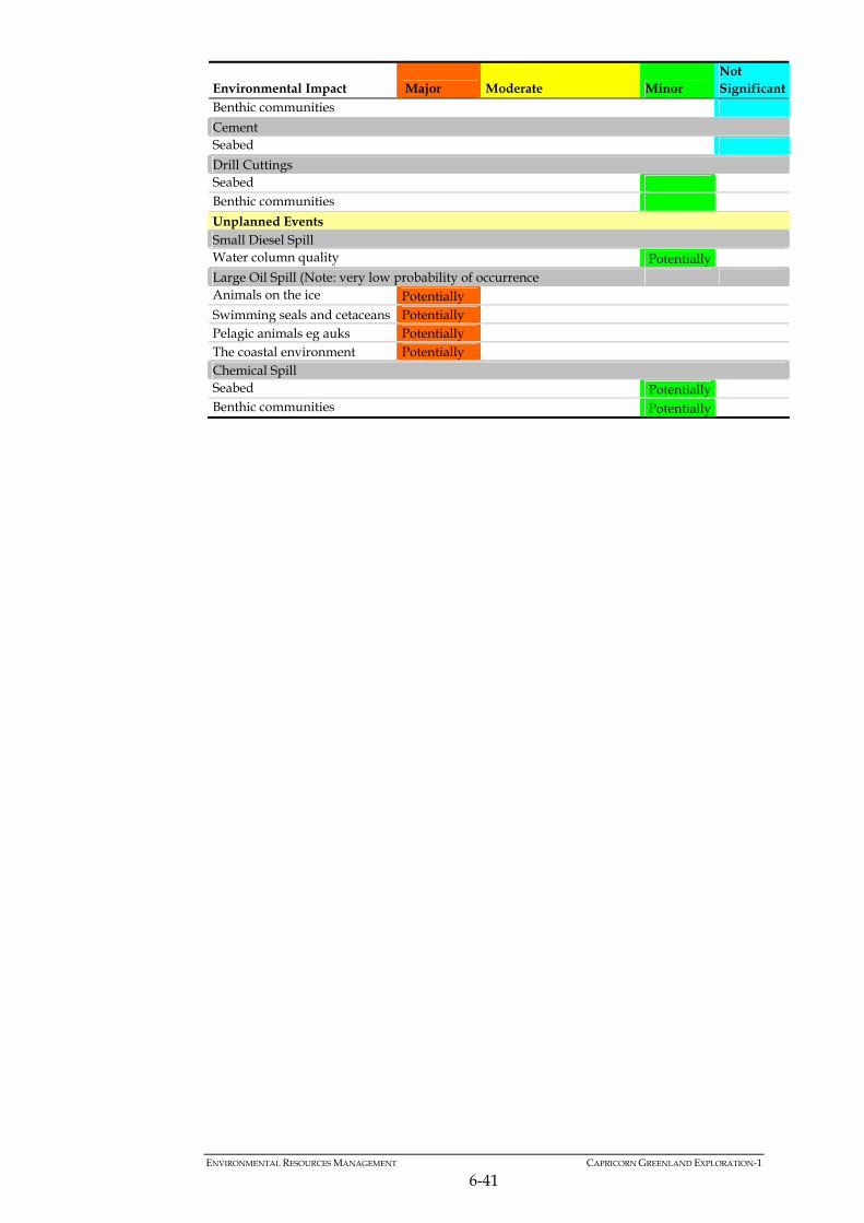
ENVIRONMENTAL RESOURCES MANAGEMENT CAPRICORN GREENLAND EXPLORATION-1
6-41
Environmental Impact Major Moderate Minor Not Significant
Benthic communities Cement Seabed Drill Cuttings Seabed Benthic communities Unplanned Events Small Diesel Spill Water column quality Potentially Large Oil Spill (Note: very low probability of occurrence Animals on the ice Potentially Swimming seals and cetaceans Potentially Pelagic animals eg auks Potentially The coastal environment Potentially Chemical Spill Seabed Potentially Benthic communities Potentially

7 ENVIRONMENTAL MITIGATION AND MONITORING
7.1 INTRODUCTION
This Chapter brings together the mitigation measures described in Chapter 6 and outlines the Environmental Management Plan (EMP) framework through which Capricorn will implement these measures. Contractors will carry out most of the HSE critical activities (onshore support, drilling rig operation, vessel operation) under Capricorn supervision and Capricorn will retain the overall responsibility and accountability for managing the Project, including HSE. Capricorn will apply and work within the commitments and procedures of the parent company Cairn Energy. In order to align procedures and clarify roles and responsibilities between Capricorn and the contracted entities for this Project, interface documents will be used to link and bridge the systems. The operations will be conducted on behalf of Capricorn by Stena Drilling, a wholly owned subsidiary of Stena AB of Sweden, which is considered to be one of the world's foremost independent drilling contractors. Stena Drilling operate under dedicated HSE management systems and fit-for-purpose operational plans and procedures. The drilling units, support vessels and logistics will also be contracted from third parties, and shall operate within the overall Capricorn project management framework. This Chapter of the EIA includes the following elements: Environmental Management; bringing together the mitigation measures
described previously and the structure, roles and responsibilities under which they will be implemented. The Environmental Management Plan will ensure that the project operates in full compliance with Capricorn’s Group Corporate Responsibility (CR) Guiding Principles.
Environmental Monitoring Plan for emissions and impacts of planned and
unplanned events. Environmental Protection Plan. Recommendations for further information relevant to the EIA as part of an
Environmental Study Plan. Offshore drilling is highly regulated and technically challenging, with high standards and expectations in HSE management, consequently it employs some of the strictest auditing and monitoring practices of any industry. For this reason a large number of HSE related procedures and practices are
ENVIRONMENTAL RESOURCES MANAGEMENT CAPRICORN GREENLAND EXPLORATION 1
7-1

embedded within the Project management framework under the overall framework of Capricorn’s Corporate Responsibility Management System. This Chapter is therefore intended as a signposting document to the relevant working practices and management procedures. Duplication of material has been avoided and this section of the EIA summarises how potential impacts will be addressed and mitigation measures implemented through the application of HSE related plans, procedures and working practices.
7.2 ENVIRONMENTAL MANAGEMENT
Environmental management of the Project will include: Cairn Energy’s corporate responsibility (CR) commitments and
procedures, comprising: o Group Health Safety and Environment (HSE) Policy (Appendix F
(a)); o Group Corporate Social Responsibility (CSR) Policy (Appendix F
(b)); o Group Security Policy; o Group Aviation Policy; and o Group Corporate Responsibility (CR) Guiding Principles (Figure
7.1). Cairn Energy Corporate Responsibility Management System (CRMS) –
which incorporates health, safety and environment (HSE), corporate social responsibility (CSR) and security.
Stena Drilling HSE philosophies and Policy Statements, implemented
through Stena operating practices and specific environmental procedures which are carried through into the overall Project Plan.
Project Plan: This document describes the specific procedures in place for
operation of the drilling units and vessels, emergencies, communications, ice management, gas detection, waste management, controlled discharges and evacuations. The Project Plan sets out how the Project will be managed and implemented and is the primary resource for implementing EIA mitigation measures during operations.
Oil Spill Response Plan (OSRP): The OSRP builds on the results of oil spill
modelling and coastal sensitivities to determine the strategies for responding to potential spills and the resources that need to be put in place.
ENVIRONMENTAL RESOURCES MANAGEMENT CAPRICORN GREENLAND EXPLORATION 1
7-2

Figure 7.1 Group Corporate Responsibility (CR) Guiding Principles
Source: Cairn Energy PLC Group Corporate Responsibility Guiding Principles 2009 Document
Cairn Energy is committed to protecting the environment and consequently manages health, safety and environment (HSE) matters as a critical business activity. The Corporate HSE Policy Statement sets out the company’s top-level objectives and commitments in this respect. Cairn Energy employs a structured approach to the management of HSE issues via a formal and documented CR Management System (CRMS). The offshore exploration drilling contractor’s HSE systems will be bridged to Cairn’s CR Management System to ensure compatibility and consistency with policies and core values. A summary of the management framework for the Project is given in Figure 7.2 below. The Project Plan outlines the systems and procedures developed to ensure that exploration drilling operations carried out on behalf of Capricorn are managed safely, with due regard for the environment and in a quality manner. Areas encompassed within this document will include: HSE Policy, Standards and Procedures; Environmental Management System; Communication; Emergency Procedures; Technical Information; Monitoring and Reporting; and Deliverables.
ENVIRONMENTAL RESOURCES MANAGEMENT CAPRICORN GREENLAND EXPLORATION 1
7-3

Figure 7.2 Sigguk Drilling Programme; Environmental Management Framework
Cairn Energy PLC
EIA and SIA
Drilling Management Support
Cuttings modelling Oil spill dispersion etc
Capricorn Greenland Exploration-1
Oil spill planning
Project Contractors ( logist ics, dr i l l ing uni ts , vessels , hel icopters etc .)
S u p p l i e r s , s u b c o n t r a c t o r s , s e r v i c e c o m p a n i e s e t c
ETC
7.3 OPERATING PROCEDURES AND EMERGENCY RESPONSE
All drilling operations as part of the Project will be conducted in accordance with the rig/vessels standard operating procedures. These procedures also detail the responses and actions to be taken in the event of an incident (e.g. fuel spill) or disruption in operating conditions. As shown in Figure 7.2, the operating procedures sit within the overall project management framework and are bridged to Capricorn’s HSEMS through the Project Plan. A summary of the Operating Procedures relevant to the HSE performance of the Project is given in Table 7.1 below. Responsibilities and lines of communication for any accidents and incidents on board the drilling vessel will follow the procedures established in the Project Plan. The roles, responsibilities and mitigation measures to be employed in order to minimise potential environmental impacts of the drilling activity are provided in the Environmental Protection Plan
Table 7.1 Operational Aspects and Related Controls and Procedure
Reference Description Management Procedures Cairn Group Corporate Responsibility (CR) Guiding Principles
Describe Cairn’s fundamental values and approach to managing CR in accordance with the Company’s Policies. The guiding principles are based on core values of Respect, Relationships and Responsibility.
Cairn HSE, Security & CSR Contingency Planning
High level guidelines to plan for managing the response to and recovery from a crisis situation.
Greenland Emergency Response Strategy
Established the overall framework and lines of communication for various emergency situations.
Project Planned and Unplanned Activities Procedures
ENVIRONMENTAL RESOURCES MANAGEMENT CAPRICORN GREENLAND EXPLORATION 1
7-4

ENVIRONMENTAL RESOURCES MANAGEMENT CAPRICORN GREENLAND EXPLORATION 1
7-5
Reference Description Ice management plan Plan for assessing threats from ice, response procedures,
contingency planning and types of ice likely to be encountered with the different response scenarios.
Leakage and detection of toxic gas
Reporting and response procedures in the case of a release of toxic gas.
Relief Well Directional Planning and Dynamic Kill Modelling Report
Plan for responding to an emergency situation using relief well drilling.
Waste Management Plan Procedures for segregating, containing and transporting waste materials, together with necessary permits and documentation for waste transfers.
Oil spill control plan Offers guidance on the actions to prevent / minimise accidental discharge of oil to sea and to mitigate the negative effects. Provides tactical and strategic responses to oil spills for use by the Emergency Response Group
Drill Unit Specific Procedures Shipboard Oil Pollution Emergency Plan
IMO and MARPOL compliant plan for preventing, responding to, controlling and reporting oil pollution incidents.
Ballast and Bilge Operations Procedures and responsibilities for operating the ballast and bilge systems on the MODUs.
Emergency Bilge and Ballast Systems
Procedures and responsibilities for operating the ballast and bilge systems in the event of an emergency.
Evacuation of All Personnel Evacuation procedures, roles and responsibilities in the case of an emergency.
Loss of Station Keeping Procedure covering the actions to be taken initially, in the event of the installation being unable to maintain station.
Maintenance Systems Procedure for operating the computer based maintenance programme.
Permit to Work System Procedures for operating and auditing the Permit to Work System (PTWS) as part of a safe system of work.
Dynamic Positioning Capability / Operations
Operational guidance relating to the positioning of the vessel and maintaining positional requirements for the safe and successful conduct and completion of operation of the vessel.
Responsibilities and lines of communication for any accidents or incidents on board the drilling units will follow the detailed procedures established in the Project Plan. Responsibilities, communications and third partly involvement will vary depending on the nature of the incident as shown in the initial response flowchart in Figure 7.3.

Figure 7.3 Initial Emergency Response Flowchart
7.4 MONITORING AND REPORTING
The contractors will routinely monitor and report through Capricorn on both the emissions and impacts of the drilling programme. Monitoring will be undertaken for specific aspects of the Project and reported through the drilling contractor to Capricorn for collating monitoring results and reporting environmental data to the Greenland authorities. Monitoring will be collated and reported according to the following breakdown: Stena Forth drilling unit; Stena Don drilling unit; and Support and Supply vessels. Monitoring and reporting encompasses the following areas: Consumption and emissions
o resources used – diesel consumption, fuel oil consumption, water received and consumed;
o liquid discharges – records of water effluent discharged and oil discharged in water effluent, bilge and ballast water discharges or quantities held in tanks for onshore disposal; and
o waste – quantities of hazardous and non-hazardous produced and management/disposal method;
ENVIRONMENTAL RESOURCES MANAGEMENT CAPRICORN GREENLAND EXPLORATION 1
7-6

ENVIRONMENTAL RESOURCES MANAGEMENT CAPRICORN GREENLAND EXPLORATION 1
7-7
o emissions to air; CH4, CO2, GHGs, NOx, SOx, VOCs, N2o and CO based on fuel consumption and standard factors;
Monitoring of environmental impacts
o incidents or unplanned events leading to a release of material to air or sea;
o any non-compliances with environmental laws and regulations; o any complaints or grievances received; o incidents or unplanned events leading to personal injury or
impacts to people; o records of location, operations, etc. o records of vessel numbers, personnel, hours worked, crew-change
schedules etc. and o records of any interaction with other vessels.
Monitoring will be undertaken on a continuous basis and the data entered into a live excel spreadsheet. A summary of the data being recorded through the Project Monitoring Plan is shown in Figure 7.4.
Figure 7.4 Extracts from the Project Key Performance Indicators for Monitoring
7.5 ENVIRONMENTAL PROTECTION PLAN
The aim of the Environmental Protection Plan (EPP) is to set out the measures which will be used to implement and monitor the proposed mitigation measures and manage the environmental performance of relevant operations.
Air EmissionsIndicator Units Jun-10 Jul-10 Aug-10 Sep-10 Oct-10 TotalCH4 tonnes 0.41 0.41 0.41 0.41 0.41 2.05CO2 tonnes 6400 6400 6400 6400 6400 32000Greenhouse Gas Emissions (GHG) tonnes CO2E 6545.01 6545.01 6545.01 6545.01 6545.01 32725.05NOX tonnes 129 129 129 129 129 645SOX tonnes 1600 1600 1600 1600 1600 8000VOCs tonnes 4.3 4.3 4.3 4.3 4.3 21.5N2O tonnes 0.44 0.44 0.44 0.44 0.44 2.2CO tonnes 27 27 27 27 27 135
Fuel Consumed Units Jun-10 Jul-10 Aug-10 Sep-10 Oct-10 TotalFuel Oil Consumed tonnes 1000 1000 1000 1000 1000 5000Diesel Consumed tonnes 1000 1000 1000 1000 1000 5000 Waste (GRI EN22)Indicator Units Jun-10 Jul-10 Aug-10 Sep-10 Oct-10Quantity of regulated hazardous waste tonnes 0
Disposed of by composting tonnesDisposed of through reuse tonnesDisposed of through recycling tonnesDisposed of through incineration or used as fuel tonnesDisposed of to landfill tonnesDisposed of by deep well injection tonnesTo on-site storage tonnesUnspecified disposal tonnes
Quantity of regulated non-hazardous waste tonnes 0 0 0 0 0Disposed of by composting tonnesDisposed of through reuse tonnesDisposed of through recycling tonnesDisposed of through incineration or used as fuel tonnesDisposed of to landfill tonnesDisposed of by deep well injection tonnesTo on-site storage tonnesUnspecified disposal tonnes

This is done by identifying areas of potential impact, proposing measures which aim to avoid or mitigate the potential for impact, and outlining the monitoring or record keeping that will be implemented to ensure the effectiveness of the mitigation measures implemented. In this way the EPP effectively serves as a conduit between the EIA and the drilling operations. The mitigation measures are provided in Table 7.2 at the end of this Chapter. Responsibilities for implementation of environmental protection measures and controls are described below. All contractor personnel, including vessel and drilling crew, will be made aware of the standards and controls applicable to the conduct of this operation before drilling commences.
7.5.1 Standards and Controls
Capricorn and its contractors will operate in accordance with all applicable laws, standards and conditions while in Greenland waters as outlines in Chapter 2: All equipment on board (engines, compressors, generators, mud and cutting treatment and sewage treatment plant, oily water separators and incinerators) will be regularly checked and maintained in accordance with manufacturer’s guidelines and the computer-based maintenance system in order to maximise efficiency and minimise malfunctions and unnecessary discharges to the environment of the survey area. A pre-drilling inspection will be undertaken and equipment checks will be carried out before drilling commences. Wastes will be appropriately segregated and stored onboard prior to disposal at properly equipped port reception facilities. Should such facilities not exist in Greenland, wastes will be contained and shipped to a suitable reception facility or else kept onboard until the vessel next visits a suitable port. Different waste types will be segregated, treated, stored and disposed of according to type and MARPOL grouping.
7.5.2 Key Responsibilities
Clear documented responsibilities, lines of communication and operational procedures will be established between the main drilling units and the various support and supply vessels before the start of drilling, including the ware ship, ice breakers, Emergency Response and Recovery / Oil Recovery Vessels, Production Support Vessel and Supply vessels. Following completion of drilling there will be a number of outstanding measures to be addressed. Post drilling phase measures will include ensuring that all reporting requirements have been fulfilled, that waste segregation and management has been completed for suitable transfer to a registered waste carrier, that any outstanding conditions of the environmental authorisation
ENVIRONMENTAL RESOURCES MANAGEMENT CAPRICORN GREENLAND EXPLORATION 1
7-8

have been satisfied and any complaints by local people or outstanding issues with other sea users in this area have been addressed and resolved. Capricorn
Capricorn will ensure that the project is carried out in accordance with the corporate commitments and policies of its parent company; Cairn Energy, and in accordance with all applicable legal requirements.
Capricorn will ensure that any conditions of the environmental approvals,
such as reporting requirements or follow-up activities, are satisfied. Capricorn will ensure that the Project operates within a comprehensive
Emergency Response Plan and implements an Oil Spill Response Plan in accordance with modelling studies and expert advice.
Capricorn will report to the Greenland authorities relevant monitoring
data from the drilling contractor on a regular basis, such as spills, waste, fuel consumption and estimated figures for emissions to air and water.
Capricorn will resolve any complaints, claims or disputes arising from
drilling operations with the Greenland Government and other affected government organisations and using testimony provided by independent observers, as necessary and appropriate.
Stena Drilling
Stena will ensure that the conduct of the MODUs will comply with the requirements of this EIA and appropriate national or international legislation.
The standards and guidelines (MARPOL etc.) referenced in Chapter 2 of
this EIA will be complied with throughout the drilling operations with records for oil and garbage documented and maintained as per normal operating practices.
Any spills or abnormal releases will be recorded and reported to the
appropriate authorities (for oil, chemicals, waste or process materials, released to air or water).
All health, safety and environmental accidents and incidents or contact
with other vessels in the project areas will be logged. Following drilling Stena shall ensure that any reporting or follow up
activities required by Capricorn are completed to Capricorn’s satisfaction including details of HSE accidents and incidents.
ENVIRONMENTAL RESOURCES MANAGEMENT CAPRICORN GREENLAND EXPLORATION 1
7-9

During drilling Stena shall regularly report consumption and emission figures to Capricorn according to the requirements of the Project Plan and including waste figures, fuel consumption, personnel on board and estimated greenhouse gas (GHG) emissions.
Stena Drilling shall appropriately store all segregated waste materials and
ensure onshore transfer of waste to an appropriate and registered waste management company at a suitable reception facility.
Vessel Operators
The vessel operator will ensure that the conduct of their vessels will comply with the requirements of this EIA and of national or international legislation.
The standards and guidelines (MARPOL etc.) referenced in Chapter 2 of
this EIA will be complied with throughout the Project and records for oil and garbage will be maintained as per normal vessel operating practices.
Any spills or abnormal releases will be recorded and reported to the
appropriate authorities (for oil, chemicals, waste or process materials, released to air or water).
All health, safety and environmental accidents and incidents or contact
with other vessels in the project areas will be logged. Where there is evidence of rafts of flightless seabirds between the area of
operations and the support base, support vessels will and take appropriate action to avoid any such rafts so long as this does not impact on safety.
7.6 SUMMARY
The proposed exploration activity will create noise, physical disturbance and atmospheric emissions, as well as producing a variety of discharges and wastes. The sources of potential impact identified in this assessment are typical of drilling activities in waters around the world. There are no unusual or unique emissions, discharges or other potential sources of environmental impact, although the operating environment is challenging with particular sensitivities and risks. The Environmental Protection Plan will apply to all aspects of the project to ensure that appropriate mitigation measures are in place to cover all eventualities. Accidental oil spills are recognised as potentially damaging to the environment and detailed dispersion modelling has been carried out. A comprehensive contingency plan will be in place to ensure an appropriate response and minimise the impact of any such event.
ENVIRONMENTAL RESOURCES MANAGEMENT CAPRICORN GREENLAND EXPLORATION 1
7-10

ENVIRONMENTAL RESOURCES MANAGEMENT CAPRICORN GREENLAND EXPLORATION 1
7-11
7.6.1 Mitigation Plan
Mitigation measures within the EIA are summarised in table format below, along with the timing and responsibility for implementing the measure.
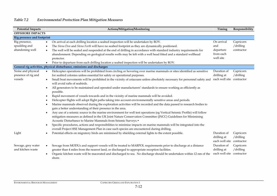
Table 7.2 Environmental Protection Plan Mitigation Measures
Potential Impacts Actions/Mitigation/Monitoring Timing Responsibility OFFSHORE IMPACTS Rig presence and footprint Rig presence, spudding and abandoning well
On arrival at each drilling location a seabed inspection will be undertaken by ROV. The Stena Don and Stena Forth will have no seabed footprint as they are dynamically positioned. The well will be sealed and suspended at the end of drilling in accordance with standard industry requirements for
abandonment. Depending on geological results wells may be left with a well head fitted and a standard wellhead protector.
Prior to departure from each drilling location a seabed inspection will be undertaken by ROV.
On arrival and departure from each well site
Capricorn /drilling contractor
General rig activities, physical disturbance, emissions and discharges Noise and physical presence of rig and vessels
Helicopter operations will be prohibited from circling or hovering over marine mammals or sites identified as sensitive for seabird colonies unless essential for safety or operational purposes.
Small boat movements will be prohibited in the vicinity of cetaceans unless absolutely necessary for personnel safety and will avoid rafts of seabirds.
All generators to be maintained and operated under manufacturers’ standards to ensure working as efficiently as possible.
Rapid movement of vessels towards and in the vicinity of marine mammals will be avoided. Helicopter flights will adopt flight paths taking into account environmentally sensitive areas and periods. Marine mammals observed during the exploration activities will be recorded and the data passed to research bodies to
gain a better understanding of their presence in the area. Any use of a seismic source in the marine environment for well test operations (eg Vertical Seismic Profile) will follow
mitigation measures as defined in the UK Joint Nature Conservation Committee (JNCC) Guidelines for Minimising Acoustic Disturbance to Marine Mammals from Seismic Surveys.•
Specific procedures, actions and responsibilities to minimise impacts on marine mammals will be integrated into the overall Project HSE Management Plan in case such species are encountered during drilling.
Duration of drilling at each well site
Capricorn /drilling contractor
Light Potential effects on migratory birds are minimised by shielding external lights to the extent possible. Duration of drilling at each well site
Capricorn /drilling contractor
Sewage, grey water and kitchen waste
Sewage from MODUs and support vessels will be treated to MARPOL requirements prior to discharge at a distance greater than 4 miles from the nearest land, or discharged to appropriate reception facilities.
Organic kitchen waste will be macerated and discharged to sea. No discharge should be undertaken within 12 nm of the shore.
Duration of drilling at each well site
Capricorn /drilling contractor
ENVIRONMENTAL RESOURCES MANAGEMENT CAPRICORN GREENLAND EXPLORATION 1
7-12
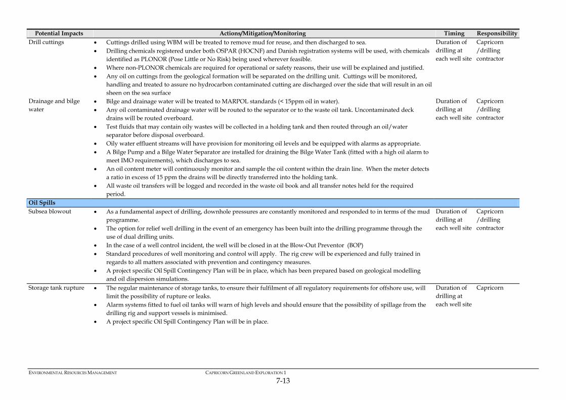
ENVIRONMENTAL RESOURCES MANAGEMENT CAPRICORN GREENLAND EXPLORATION 1
7-13
Potential Impacts Actions/Mitigation/Monitoring Timing Responsibility Drill cuttings Cuttings drilled using WBM will be treated to remove mud for reuse, and then discharged to sea.
Drilling chemicals registered under both OSPAR (HOCNF) and Danish registration systems will be used, with chemicals identified as PLONOR (Pose Little or No Risk) being used wherever feasible.
Where non-PLONOR chemicals are required for operational or safety reasons, their use will be explained and justified. Any oil on cuttings from the geological formation will be separated on the drilling unit. Cuttings will be monitored,
handling and treated to assure no hydrocarbon contaminated cutting are discharged over the side that will result in an oil sheen on the sea surface
Duration of drilling at each well site
Capricorn /drilling contractor
Drainage and bilge water
Bilge and drainage water will be treated to MARPOL standards (< 15ppm oil in water). Any oil contaminated drainage water will be routed to the separator or to the waste oil tank. Uncontaminated deck
drains will be routed overboard. Test fluids that may contain oily wastes will be collected in a holding tank and then routed through an oil/water
separator before disposal overboard. Oily water effluent streams will have provision for monitoring oil levels and be equipped with alarms as appropriate. A Bilge Pump and a Bilge Water Separator are installed for draining the Bilge Water Tank (fitted with a high oil alarm to
meet IMO requirements), which discharges to sea. An oil content meter will continuously monitor and sample the oil content within the drain line. When the meter detects
a ratio in excess of 15 ppm the drains will be directly transferred into the holding tank. All waste oil transfers will be logged and recorded in the waste oil book and all transfer notes held for the required
period.
Duration of drilling at each well site
Capricorn /drilling contractor
Oil Spills Subsea blowout As a fundamental aspect of drilling, downhole pressures are constantly monitored and responded to in terms of the mud
programme. The option for relief well drilling in the event of an emergency has been built into the drilling programme through the
use of dual drilling units. In the case of a well control incident, the well will be closed in at the Blow-Out Preventor (BOP) Standard procedures of well monitoring and control will apply. The rig crew will be experienced and fully trained in
regards to all matters associated with prevention and contingency measures. A project specific Oil Spill Contingency Plan will be in place, which has been prepared based on geological modelling
and oil dispersion simulations.
Duration of drilling at each well site
Capricorn /drilling contractor
Storage tank rupture The regular maintenance of storage tanks, to ensure their fulfilment of all regulatory requirements for offshore use, will limit the possibility of rupture or leaks.
Alarm systems fitted to fuel oil tanks will warn of high levels and should ensure that the possibility of spillage from the drilling rig and support vessels is minimised.
A project specific Oil Spill Contingency Plan will be in place.
Duration of drilling at each well site
Capricorn

ENVIRONMENTAL RESOURCES MANAGEMENT CAPRICORN GREENLAND EXPLORATION 1
7-14
Potential Impacts Actions/Mitigation/Monitoring Timing Responsibility Spill during fuelling Refuelling operations will be conducted in calm weather conditions and rigorous monitoring of the refuelling operations
will be carried out. Alarm systems will be fitted to fuel oil tanks to warn of high levels and should ensure the possibility of spillage from the
drilling rig and support vessels is minimised. Diesel and heavy fuel oil spill scenarios are covered in the Oil Spill Contingency Plan.
Duration of drilling at each well site
Capricorn /drilling contractor contractors
Vessel collision First emphasis will be on prevention as per the Project Health and Safety Plan A full Spill Contingency Plan will be in place to control and recover from incidents. Planning and execution of the rig move will ensure that the routing pattern will minimise effects on passing vessels. Significant levels of Vessel traffic in the Licence Block are uncommon. Prior and ongoing consultation and notification of other sea users (eg fishing and shipping interests) will ensure they are
aware of the potential hazards and can plan accordingly. The standby vessels will continually monitor vessels and their positions during drilling to ensure no navigational
obstruction. A minimum distance of approach of 500 m will be applied for all non-relevant traffic with the assistance of support and
standby vessels. An ice management plan will be adopted to help minimise the risk of collision with icebergs.
Duration of drilling at each well site
Capricorn /drilling contractor
Chemical Spill Cementing The vast bulk of the cement mixture is comprised of cement and barite; chemical additives are in very small proportions.
The majority of these chemicals are controlled in accordance with the OSPAR chemical notification scheme, which ensures that chemicals are not toxic to the environment at the quantities released.
Duration of drilling at each well site
Capricorn /drilling contractor
Vessels and Rig With minor exceptions the chemicals stored on board will be of inherent low toxicity and classify as the lowest toxicity rating under the OSPAR chemical notification format.
Storage and handling on board will be subject to strict provisions in terms of environmental protection and human safety.
The drilling contractor maintains Operating Procedures for the safe and secure handling of chemicals and materials. Onshore disposal of wastes will be subject to the Waste Management Plan. All vessels and their discharges will be MARPOL compliant. The drilling units and support vessels will be equipped with materials (e.g. absorbent pads) to contain and collect spills.
Crews will be trained in the use of such materials and contingency measures will be implemented for even the smallest of spills.
A full Spill Contingency Plan will be in place to control and recover from incidents.
Duration of drilling at each well site
Capricorn / vessel captains and drilling contractor
Waste Management Atmospheric emissions
All generators to be maintained and operated under manufacturers’ standards to ensure working as efficiently as possible.
To the extent possible, the power generators and vessel engines will be operated efficiently. Fuel will be arctic grade low sulphur fuel (<1.5% sulphur)
Duration of drilling at each well site
Capricorn /drilling contractor

ENVIRONMENTAL RESOURCES MANAGEMENT CAPRICORN GREENLAND EXPLORATION 1
7-15
Potential Impacts Actions/Mitigation/Monitoring Timing Responsibility Sewage / gray water and kitchen waste
The drilling units will be equipped with sewage treatment units, compliant with MARPOL Annex IV regulations for disposal of wastes at sea.
Sewage from support vessels will be treated to MARPOL requirements (ie ground and disinfected) prior to discharge in open waters, or discharged to appropriate reception facilities.
Rig procedures to be in place to ensure that food is macerated and disposed overboard as good sanitary practice, as per MARPOL regulations.
Duration of drilling at each well site
Capricorn /drilling contractor
Domestic waste and hazardous waste
All solid wastes, including any oil recovered from the slops tank or drains, will be stored for transfer to shore and then onward shipment and disposal at appropriate licensed facilities. No waste materials, other than cuttings and food waste, will be discharged to sea
All wastes will be managed and disposed of according to the Waste Management t Plan, the Duty of Care and relevant legislation.
Duration of drilling at each well site
Capricorn /drilling contractor
ONSHORE IMPACTS Transport Terrestrial traffic Crew changes will normally be undertaken by helicopter and fixed wing transfer to the international airport at
Kangerlussuaq and vehicle movements will therefore be minimised. Supplies and materials will be transferred by supply boat either from the wareship or onshore supply base to the Project
area. Onshore vehicle movements will therefore be minimised and temporary (over the project duration only).
During onshore operations
Capricorn / Logistics and transport contractors
Aircraft traffic Helicopter transfers will be a temporary impact over the duration of the project and will consist of approximately 2 return flights per day 5 days per week. Helicopters are the safest method for transferring personnel to an offshore installation.
Fixed wing flights will be used to transfer personnel from Kangerlussuaq to Aasiaat with an estimated 1 flight per day 5 days per week.
Personnel numbers and crew changes will be planned in advance to minimise unnecessary flights and maximise the efficiency of personnel movements.
During onshore operations
Capricorn / Logistics and transport contractors
Vessel Movements Shipping activity (fuelling of supply vessels)
Refuelling and resupply may be provided by Royal Arctic Line (RAL) in Greenland. It is intended to use the RAL base at Sisimiut with further storage and re-supply facility provided by the ware ship (offshore). This will reduce the level of support and space required at the onshore facilities.
It is intended to use low sulphur fuels to minimize emissions.
During onshore operations
Capricorn / Royal Arctic Line

ENVIRONMENTAL RESOURCES MANAGEMENT CAPRICORN GREENLAND EXPLORATION 1
7-16
Potential Impacts Actions/Mitigation/Monitoring Timing Responsibility Waste Management Waste disposed of onshore, or generated from shore facilities
Waste will be segregated into hazardous and non-hazardous on board MODUs and vessels. Skip transfers will be netted to avoid the release of material and transferred to a registered waste management company
onshore where suitable treatment/disposal facilities exist in Greenland. Where suitable treatment/disposal facilities do not exist in Greenland, waste will be held on board or transferred in
compliance with national and international legislation to an approved reception facility. MODUs and vessels will strictly follow MARPOL requirements for waste. Scrap metal will be separated for recycling. Medical waste will be incinerated. Waste oils etc will be separated for recycling. Potentially hazardous wastes will be safely stored prior to export for treatment/disposal at an appropriate facility
overseas. A record will be maintained of wastes arising, their treatment and disposal routes in accordance with the Waste
Management Plan. Spot checks and visual inspections will be undertaken to ensure the plan is being adhered to.
During onshore operations
Capricorn / Royal Arctic Line

7.7 ENVIRONMENTAL STUDY PLAN
A considerable amount of new environmental data has been acquired for the purposes of this EIA, both by Capricorn and its contractors and by research institutes and non-governmental organisations (NGOs) in Greenland and Denmark. Environmental studies and datasets have included: Meteorological and oceanographic studies; Deployment of current meters offshore; Vessel and satellite based studies into ice presence and movements; Geological studies using seismic data; Seabed topography and detailed bathymetry from site surveys; Sediment sampling and both physical analysis (eg particle size) and
chemical analysis (eg presence of metals or hydrocarbons); Water quality analysis; Sampling and analysis of sea bottom (benthic) species and habitats; Marine mammal observations from seismic and site survey vessels; Northern extension of the oil spill sensitivity atlas by NGOs In-country stakeholder consultations and public engagement; Cuttings dispersion modelling; and Oil spill trajectory simulations; This body of data (where it is not commercially sensitive or confidential for operational reasons) will be made available to relevant Government bodies and NGOs in Greenland to further the understanding of the offshore environment. Environmental studies will continue during the Project and additional information will be released as it becomes available. Recommendations for further environmental studies include: Acquiring additional geophysical and environmental data for any future
drilling locations other than those already surveyed (the 1st two drilling locations).
Carrying out marine mammal observations in accordance with the JNCC
Guidelines where a seismic source is being used in the marine environment.
Compiling and releasing seabed visual observations from ROV surveys
where these provide information on seabed habitats or species. Despite the Project taking place during summer months outside the main
periods of ice cover, extending the oil spill study to examine potential interactions between oil releases and ice presence/movements would complement the existing work carried out and provide a valuable studies for this area going forward.
ENVIRONMENTAL RESOURCES MANAGEMENT CAPRICORN GREENLAND EXPLORATION 1
7-17
Related Documents