.. .-..- E ORNL/TM=8100 Design and Analysis of a 5-MW Vertical-Fluted-Tube Condenser - 7 for Geothermal Applications G. H. Llewellyn 4 ' * , -..

Welcome message from author
This document is posted to help you gain knowledge. Please leave a comment to let me know what you think about it! Share it to your friends and learn new things together.
Transcript
.. .-..- E
ORNL/TM=8100
Design and Analysis of a 5-MW Vertical-Fluted-Tube Condenser -7
for Geothermal Applications
G. H. Llewellyn
4 ' * , -..

DISCLAIMER
This report was prepared as an account of work sponsored by an agency of the United States Government. Neither the United States Government nor any agency Thereof, nor any of their employees, makes any warranty, express or implied, or assumes any legal liability or responsibility for the accuracy, completeness, or usefulness of any information, apparatus, product, or process disclosed, or represents that its use would not infringe privately owned rights. Reference herein to any specific commercial product, process, or service by trade name, trademark, manufacturer, or otherwise does not necessarily constitute or imply its endorsement, recommendation, or favoring by the United States Government or any agency thereof. The views and opinions of authors expressed herein do not necessarily state or reflect those of the United States Government or any agency thereof.

DISCLAIMER Portions of this document may be illegible in electronic image products. Images are produced from the best available original document.

Printed in the United States of America. Available from National Technical Information Service
U.S. Department of Commerce 5285 Port Royal Road, Springfield, Virginia 22161
NTlS price codes-Printed Copy: A07 Microfiche A01 I
This report was prepared as an account of work sponsored by an agency of the United StatesGovernment. Neither theU nited StatesGovernment nor any agency thereof, nor any of their employees, makes any warranty, express or implied, or assumes any legal liability or responsibility for the accuracy, completeness, or usefulness of any information, apparatus, product, or process disclosed, or represents that its use would not infringe privately owned rights. Reference herein to any specific commercial product, process, or service by trade name, trademark, manufacturer, or otherwise, does not necessarily constitute or imply its endorsement, recommendation, or favoring by the United StatesGovernment or any agency thereof. The views and opinions of authors expressed herein do not necessarily state or reflect those of the United StatesGovernment or any agency thereof.

ORNL/TM--8 100 ORNL/TM-8100
Dist. Category UC-66d
' DE82 008707
Contract No. W-7405-eng-26
Engineering Division for ORNL Energy Division
DESIGN AM, ANALYSIS OF A 5-MW VERTICAL-FLUTED-TUBE CONDENSER FOR GEOTHERMAL APPLICATIONS
G. H. Llewellyn
'1- DISCLAIMER .
Date Published - March 1982 NOTICE
PORTIONS OF THIS REPORT ARE ILLEGIBLE. It has been reproduced from the best available copy to permit the broadest posdbte avati- a bi Iity.
OAK RIDG NAL LABORATORY Oak Ridge, Tennessee 37830
opeiated by
NUCLEAR DIVISION for the
DEPARTMENT OF ENERGY
ION CARBIDE CORPORATION
DlSTRllUTlON OF THIS DOCUMENT IS UlllMlTED n

CONTENTS
Page
LISTOFFIGURES 0 v
LISTOFTABLES s . Vii
AESTRACT . . . . . . . . . . . . . . . . . . . . . . . . . . . . . 1
1 . INTRODUCTION . 1
2 . S.Y . . . . . . . . . . . . . . . . . . . . . . . . . . . 5
3 . HISTORY OF FLUTED TUBES . . 7
4 . INDUSTRIAL APPLICATIONS 11
5 . FLUTEDTUBEMANUFACTURE . . . . . . . . . . . . . . . . . . . 13 6 . EXPERIMENTAL WORK AT OWL . . . . . . . . . . . . . . . . . . 19
7 . HEAT TRANSFER CALCULATIONS . . . . . . . . . . . . . . . . . 31 7.1 Properties of Liquid and Vapor Streams . . . . . . . . . 31 7.2 Tubeside Heat Transfer Coefficient . . . . . . . . . . . 32 7.3 Shellside Heat Transfer Coefficient . . . . . . . . . . 36 7.4 Fouling . . . . . . . . . . . . . . . . . . . . . . . . 40 7.5 Overall Heat Transfer . . . . . . . . . . . . . . . . . 42 7.6 Log Mean Temperature Difference . . . . . . . . . . . . . 44
8 . PRESSURE DROP CALCULATIONS . . . . . . . . . . . . . . . . . 47 8.1 Tubeside Pressure Drop . . . . . . . . . . . . . . . . . 47 8.2 Shellside Pressure Drop . . . . . . . . . . . . . . . . 49
9 . DESIGN VARIABLES AND OPTIMIZATION . . . . . . . . . . . . . . 55
10 . CONDENSER DESIGN . 61 10.1Design Criteria and Code Requirements . . . . . . . . . 62 10.2 Design Description . . . . . . . . . . . . . . . . . . . 63 10.3 Vibrational Analysis . . . . . . . . . . . . . . . . . . 71
75 10.5 Sire Testing . . . . . . . . . . . . . . . . . . . . . . 78 10.4 Data Acquisition and Instrumentation . . . . . . . . . .
11 . RELATED PRESENT AND FUTURE WORK . 81
12 . CONCLUSIONS AND RECOMMENDATIONS . . . . . . . . . . . . . . . 85 ACKNOWLEDGMENTS . . . . . . . . . . . . . . . . . . . . . . . . . 87
.REFERENCES . . . . . . . . . . . . . . . . . . . . . . . . . . . . 89
iii

BIBLIOGRAPHY. . . . Appendix A. CONVERSIONS (METRIC/ENGLISH, ENGLISH/METRIC)
Appendix B. PROPERTIES OF ISOBUTANE . . . . . . . . . . Appendix C. PROPERTIES OF WATER . . . . . . . . . . . . . Appendix D. SHELLSIDE PRESSURE DISTRIBUTION . . . . . .
. Page
95
103
105
109
111
bi
I
iv (rr
1

LIST OF FIGURES
tsl Figure
9
10
11
12
13
14
Modifications t o test loop a t the Geothermal Cortrponents T e s t F a c i l i t y a t East Mesa, Cal i fornia . . . . . . . . . . Fluted tube showing the Gregorig e f f e c t . . . . . . . . . . Production method used by Toshiba Metal Products Division, Tokoyo, Japan showing typica l f l u t e paterns . . . Tube-rolling machine developed by Grob, Inc., Grafton, Wisconsin . . . . . . . . . . . . . . . . . . . . Design spec i f ica t ions f o r the manufacture of the E-tube . . . . . . . . . . . . . . . . . . . . . . . . . . Photomicrograph of a cross sect ion of a carbon steel E-tube produced by Grob., Inc. . . . . . . . . . . . . . . . Enhancement f ac to r s f o r condensing R-115 on E- and F- tubes compared with smooth tubes with no drainage s k i r t s as functions of heat f l ux . . . . . . . . . . . . . Enhancement f ac to r s f o r condensing R-113 on E- and F-tubes compared with smooth tubes with no drainage s k i r t s as functions of heat f l ux . . . . . . . . . . . . . Enhancement fac tors f o r condensing R-11 on E- and F-tubes compared with smooth tubes with no drainage s k i r t s as functions of heat f l ux . . . . . . . . . . . . . . Enhancement fac tors f o r condensing various refrigerants on E-tubes as functions of'heat flux . . . . . Effect of length on condensation coef f ic ine ts of R-11 on A- and F-tubes at heat f luxes from 9,450 t o 28,000 W/m2 (3,000 t o 9,000 Btu/h*ft2) . . . . . . . . . . . . . . . . Effect of length of F-tube on the condensing coef f ic ien ts f o r various vapors a t d i f f e ren t heat f l u x e s . . . . . . . . . . . . . . . . . . . . . . . . ORNL 40-tube vertical-fluted-tube condenser t e s t ed a t the East Mesa Geothermal T e s t S i t e . . . ORNL 104-tube vertical-fluted-tube condenser t e s t ed a t Raft River Geothermal T e s t S i t e . . . . . . . . . . . .
Page
3
8
14
16
17
17
21
22
22
23
25
25
26
, 27
V

!
Figure Page
15 Comparison of tubeside heat transfer correlations in East Mesa condenser for turbulent flow as functions of flow rate at 300 K (8O0F) . . . . . . . . . . . . . . . 35
16 Inundation correction factor for single smooth tube horizontal condensers as a function of the number of vertical rows . . . . . . . . . . . . . . . . . . . . . 37
17 Effect of air concentration on the .condensing coefficient of steam . . . . . . . . . . . . . . . . . . . 39
18 Experimental shellside condensing coefficients obtained for E-tubes . . . . . . . . . . . . . . . . . . . . . . . . 41
19 Overall heat transfer coefficient as a function of the condensing coefficient for the East Mesa condenser at a coolant flow rate of 0.22 m3/s (3500 gpm) . . . . . . . . . . . . . . . . . . . . . . . . 43
20 Tubeside and shellside temperature distribution as a function of length for the East Mesa condenser . . . . . . 46
21 Component shellside pressure drops in the East Mesa condenser . . . . . . . . . . . . . . . . . . . . 52
22 Cross section of ORNL 5-MW vertical-fluted-tube condenser . . . . . . . . . . . . . . . . . . . . . . . . . 64
23 Detail showing condenser gas sample and venttubes . . . . . . . . . . . . . . . . . . . . . . . . 67
24 Tube bundle of ORNL 5-MW vertical-fluted-tube condenser . . . . . . . . . . . . . . . . . . . . . . . . . 68
25 Exterior view of ORNL 5-MW vertical-fluted-tube condenser showing header details . . . . . . . . . . . . . 69
26 Full-length exterior view of ORNL 5-MW vertical- fluted-tube condenser . . . . . . . . . . . . . . . . . . . 70
27 Tube vibration criteria diagram . . . . . . . . . . . . . . 73 -8 Acoustic resonance diagram . . . . . . . . . . . . . . . . 76
29 Relative cost of saline resistant tube materials (March 15, 1981) . . . . . . . . . . . . . . . . . . . . . 82
vi
i
LIST OF TABLES
Table Page
1 Characteristics of A-, E-, and F-tubes . . . . . . . . . . 20
2 Comparison of refrigerant properties at 311 K (100'F) . . . . . . . . . . . . . . . . . . . . . . . 20
3 Comparison of ORNL condensers tested at geothermal test facilities . . . . . . . . . . . . . . . . . . . . . . 28' Heat load on East Mesa condenser using direct contact heat exchanger . . . . . . . . . . . . . . . . . . 57
4
5 Tube requirements for East Mesa condenser . . . . . . . . . 58
6 Allocation of downcomers on baffles . 65
7 Natural frequencies in tube passes for 5-MW ORNL East Mesa condenser . . . . . . . . . . . . . . . . . 72
vii

DESIGN AND ANALYSIS OF A 5-MW VERTIW-FLUTED-TE CONDENSER FOR GEOTHERMAL APPLICATIONS
G. H. Llewellyn
ABSTRACT
This report covers the design and analysis done a t the Oak Ridge National Laboratory of an industrial-sized vertical- fluted-tube condenser. The condenser is used to condense superheated isobutane vapor discharged from a power turbine i n a geothermal test f a c i l i t y operated f o r the U.S. Department of Energy. The 5-MW condenser has 1150 coolant tubes i n a four ass confi uration with a t o t a l heat t ransfer area of
Components T e s t Fac i l i ty i n the Imperial Valley of East Mesa, California. The condenser design is based on previous experi- mental research work done a t the Oak Ridge National Laboratory on condensing re f r igerants on a wide var ie ty of s ing le v e r t i c a l tubes. Condensing f i lm coeff ic ients obtained on the high-performance v e r t i c a l f luted tubes i n condensing refr ig- e ran ts are as much as seven t i m e s greater than those obtained with v e r t i c a l smooth tubes tha t have the same diameter and length. the f lu t ed tube condedser is four to f i v e times the heat t ransfer obtained from the ident ica l un i t s employing smooth tubes. Fluted tube condensers a l so have other d i r e c t applica- t ions i n the Ocean Thermal Energy Conversion (OTEC) program i n condensing ammonia, i n the petroleum industry i n condensing l i g h t hydrocarbons, and i n the air conditioning and refrigera- t i on industry i n condensing fluorocarbon vapors.
725 m -! (7800 f t !3 ). The un i t i s being tes ted a t the Geothermal
The overa l l heat t ransfer performance expected from
1. INTRODUCTION
The U.S. Department of Energy (DOE), Division of Geothermal Energy,
asked the Oak Ridge National Laboratory ( O m ) t o design and evalute
a 5-MW (17 x lo6 Btu/h) vertical-fluted-tube condenser based on previous
experimental work on condensing re f r igerants on s ingle f luted tubes.
To demonstrate the f e a s i b i l i t y of obtaining energy from geothermal
br ine deposits, test faci l i t ies were developed i n the western states.
A test loop has been b u i l t a t the Geothermal Component T e s t Fac i l i ty
(GCTF) a t East Mesa, California, by Barber-Nichols Engineering
Company of Arvada, Colorado.
Lawrence Berkeley Laboratories (LBL).
The work has been under the d i rec t ion of
W
1
2
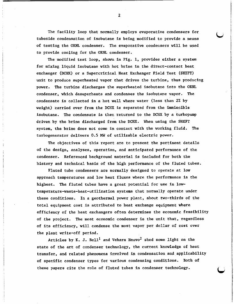
The facility loop that normally employs evaporative condensers for tubeside condensation of isobutane is being modified to provide a means of testing the ORNL condenser. The evaporative condensers will be used to provide cooling for the ORNL condenser.
The modified test loop, shown in Fig. 1, provides either a system for mixing liquid isobutane with hot brine in the direct-contact heat exchanger (DCHX) or a Supercritical Heat Exchanger Field Test (SHEFT) unit to produce superheated vapor that drives the turbine, thus producing power. condenser, which desuperheats and condenses the isobutane vapor. condensate is collected in a hot well where water (less than 2% by weight) carried over from the DCHX is separated from the immiscible isobutane. driven by the brine discharged from the DCHX. system, the brine does not come in contact with the working fluid. turbogenerator delivers 0.5 MW of utilizable electric power.
The turbine discharges the superheated isobutane into the ORNL
The
The condensate is ther, returned to the DCHX by a turbopump When using the SHEFT
The
The objectives of this report are to present the pertinent details of the design, analyses, operation, and anticipated performance of the condenser. Referenced background material is included for both the history and technical basis of the high performance of the fluted tubes.
Fluted tube condensers are normally designed to operate at low approach temperatures and low heat fluxes where the performance is the highest. temperature-waste-heat-utilization systems that normally operate under these conditions. total equipment cost is attributed to heat exchange equipment where efficiency of the heat exchangers often determines the economic feasibility
The fluted tubes have a great potential for use in low-
In a geothermal power plant, about two-thirds of the
of the project. of its efficiency, will condense the most vapor per dollar of cost over the plant write-off period.
The most economic condenser is the unit that, regardless
Articles by K. J. Bell' and Vehara Heuvo' shed some light on the state of the art of condenser technology, the current knowledge of heat transfer, and related phenomena involved in condensation and applicability of specific condenser types for various condensing conditions. Both of
! these papers cite the role of fluted tubes in condenser technology.

3
ISIDIE roll nuIufCTDN M O W U l
Fig. 1. Modifications to test loop at the Geothermal Components Test Facility at East Mesa, California.
Recent articles by Jerry Taborek of the Heat Transfer Research Institute (HTRI) concerning the state of the art in heat exchanger design3 and in design techniques4 w e r e found to be excellent sources of information. condenser. is that:
These ideas were used to formulate a design for the ORNL The main points gleaned from review of these references
1. Film condensation of multicomponent mixtures containing immiscibles and noncondensables involving vapor shear is a very complex problem. Even with the aid of the computer, it has been impossible to find nonproprietary methods expressing the relationships of all these variables.
U
4
2. The effect of noncondensables is not fully understood, particularly with vapor shear. u
3. Too often, the failure of an exchanger is attributed t o not using the "right" fouling factor rather than acceptance of the fact that an exchanger was poorly designed.
One objective in the design of this exchanger 'is to obtain the highest allowable tubeside and shellside velocities using average fouling conditions while transferring the specified heat load. factor on the thermal desfgn of the condenser is the flow rate and pres-
The controlling
sure drop for the tubeside and shellside fluids. is controlled by the operating temperature and pressure and the pertinent code requirements.
The mechanical design
biJ
2. SUMMARY
Over the pas t t h i r t y years, many types of f lu t ed surfaces have b-en developed f o r condensing steam, ammonia, hydrocarbons, and
fluorocarbons; these surfaces can be custom designed f o r spec i f i c
vapors.
on a wide var ie ty of f lu t ed tubes.
ORNL has done extensive t e s t ing in condensing re f r igerants
Based on t h i s t e s t ing , ORNL has become ac t ive ly engaged i n the
design, procurement, and t e s t i n g of vertical-fluted-tube condensers
(VFTC) over a wide capacity range.
1150 tubes have been b u i l t t o date, and a 2500 tube unit i s current ly
being investigated. Carbon steel, aluminum, titanium, admiralty,
cupronickels, and spec ia l sal ine-resis tant s t a i n l e s s steel a l loys
have been used t o fabr ica te the f lu ted tubes.
Units containing 2, 40, 104, and
As a pa r t of the DOE Waste Heat Rejection Program (AM Program),
ORNL has developed, designed, and b u i l t a 1150-tube VFTC that w i l l be
t e s t ed and evaluated at the GCTF a t E a s t Mesa, California.
is concerned with the d e t a i l s of the development and design of t h i s
1150-tube unit .
appl icat ion f o r steam turbine condensers, and the power industry i n
Japan is a l s o invest igat ing possible application.
from ORNL experience using f lu t ed tubes f o r she l l s ide condensation can
be summarized as follows where enhancements r e f e r t o comparison i n con-
densing heat transfe-r coef f ic ien ts obtained on vertical f lu ted tubes
t o those obtained on v e r t i c a l smooth tubes.
This report
The U.S. Navy has recent ly indicated i n t e r e s t i n VFTC
Incentives derived
Commercial i n s t a l l a t i o n s have reported enhancements i n Condensing
heat t r ans fe r coef f ic ien ts as high as 10 when condensing l i g h t
hydrocarbons at high vapor ve loc i t ies .
The ove ra l l heat t ransfer from a vertical-fluted-tube condenser is
expected t o be 4 t o 6 times t h a t f o r a horizontal unit with the
same t o t a l length of smooth tubes a t lower vapor ve loc i t ies . Addi-
t i o n a l performance can be gained by providing c loser ba f f l e spacing
a t the expense of higher cos t and she l l s ide pressure drop. The
majority of t h i s enhancement i s a t t r i b u t e d t o the f lu ted tubes.
5

6
0 Cost per unit length of fluted tubes is 1.25 to 4 times higher than for smooth tubes and depends on the tube material used. mass production, it is conceivable that fluted tubes could be produced at a cost premium of less than 25%.
With
The cost of a vertical condenser with carbon steel fluted tubes can be as much as 40% higher than a horizontal-smooth-tube unit but would transfer about 6 times the heat.
Vertical-fluted-tube condensers can be built at 40 t o 50% of the cost of horizontal-smooth-tube units having the same heat load.
Custom-made flutes can be fabricated into standard-sized tubing using most commercially available malleable metal or metal alloys.

3. HISTORY OF FLUTED TUBES
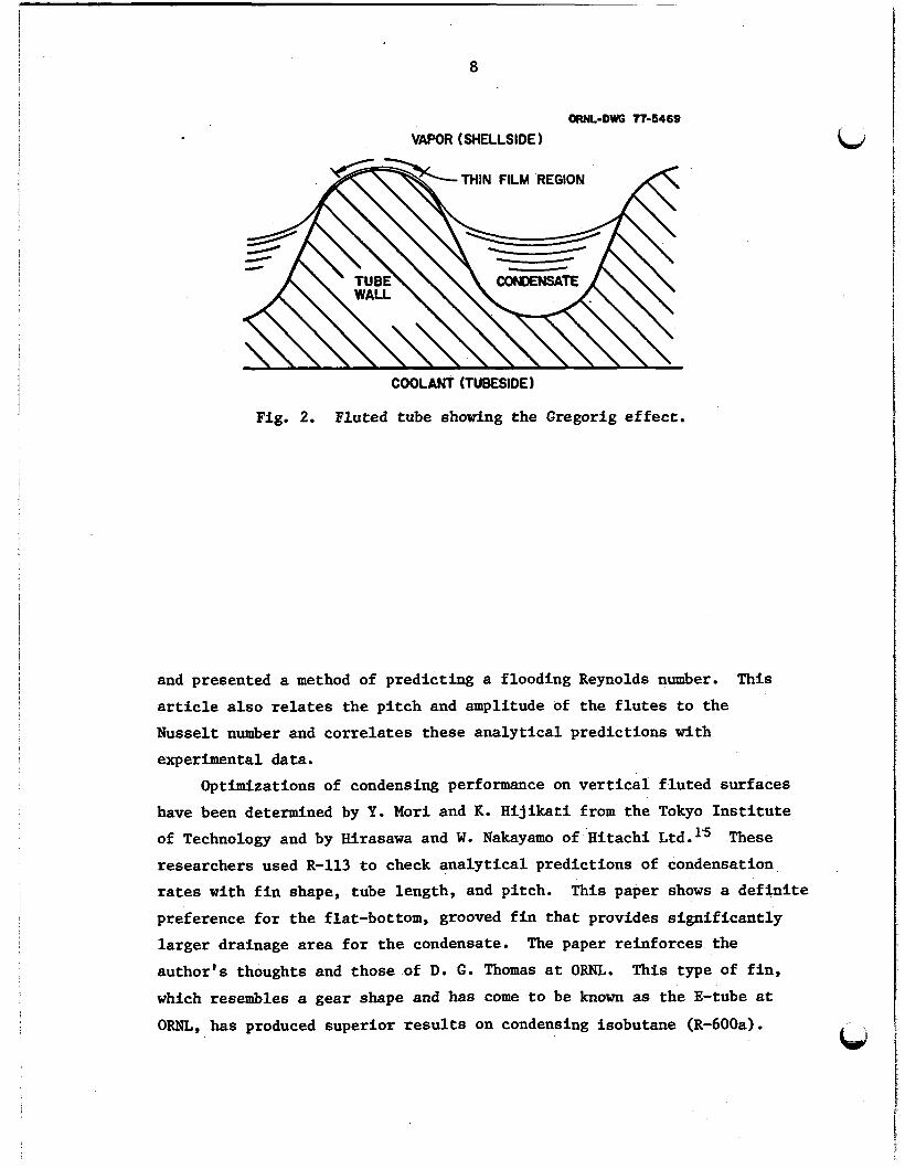
The h&h performance of the fluted tubes employed on these exchangers
is primarily due to the Gregorig effect, in which the surface tension forces move the condensate from the crest of the flute into the troughs
where it drains by gravity (shown in Fig. 2).
In 1957, R. Gregorig5 obtained increases in condensing coefficients of 2 to 8 times in condensing steam on vertical-fluted surfaces compared with vertical-smooth surfaces. formulation for design in this disclosure and left things rather vague as to optimization of the design surface.
R. L. Webb6 of Pennsylvania State University recently developed a method of optimizing the Gregoric condensing surface but based his calcula- tions on ideal conditions. Webb concluded from his studies that each condensable has an optimum flute pattern based on the physical properties of the condensate.
Gregorig, however, did not present a
In 1965, T. C. Carnavos7 reported obtaining condensing enhancements from 4.5 to 7.
in the overall heat transfer as high as 7 in condensing steam. Alexander and Hoffman* in 1971 obtained enhancements
In 1968, D. G. Thomasg* lo obtianed condensing enhancement factors as high as 9 using loosely clamped wires and longitudinal fins attached to the tubes. that higher enhancements could be obtained with properly designed, closely spaced fins than with sinusodial flutes.
As a result of his experiments, Thomas was convinced
Host of the previously mentioned experimental work on single-fluted tubes has been done in condensing steam on the exterior surface of the tube. in condensing ammonia on vertical fluted tubes have been made by A. E. Bergles and M. K. Jensenll and were directed toward Ocean Thermal Energy Conversion (OTEC) application.
vertical12 and inclinedl fluted tubes.
Recent surveys of data on single-phase heat transfer experiments
S. K. Combs of ORNL has done ork in condensing ammonia on the exterior surface of both
nd Bell14 have analyzed isothermal flow and gravity- controlled 'flow on vertical fluted surfaces for Nusselt-type condensation
7
8
ORNL-DWG 77-5469
VAPOR (SHELLSIDE 1
~
COOLANT (TUBESIDE 1
Fig. 2. Fluted tube showing the Gregorig effect.
and presented a method of predicting a flooding Reynolds number. article also relates the pitch and amplitude of the flutes to the Nusselt number and correlates these analytical predictions with experimental data.
This
Optimizations of condensing performance on vertical fluted surfaces have been determined by Y. Mori and K. Hijikati from the Tokyo Institute of Technology and by Hirasawa and W. Nakayamo of Hitachi Ltd.1'5 These researchers used R-113 to check analytical predictions of condensation rates with fin shape, tube length, and pitch. This paper shows a definite preference for the flat-bottom, grooved fin that provides significantly larger drainage area for the condensate. author's thoughts and those of D. G. Thomas at ORNL. which resembles a gear shape and has come to be known as the E-tube at ORNL, has produced superior results on condensing isobutane (R-600a).
The paper reinforces the This type of fin,
9
It is thought possible that this design might be optimized even csi further with additional experimental work.
The factors that determine the lineal condensation rate on a verttcal fluted tube at given vapor and coolant conditions are summarized:
condensate properties, 0 flute configuration,
baffle spacing, vapor contaminants (oil, water, noncondensables) , tubeside fouling, shellside fouling, and tube material.
In horizontal condensers, as the number of the tube rows is increased, the condensate is successively dumped on the lower row of tubes causing a thicker condensate film to build up, consequently increasing the thermal resistance. This phenomenon is known as inundation. Carryover called "rain" associated with a vertical tube bundle is present, but it does not exhibit the pronounced reduction in heat transfer observed in horizontal units. the tubes and reduce the amount of rain generated in vertical units.
The flutes curtail striping of the condensate from
The ratio of shellside condensing heat transfer Coefficients for a single snooth horizontal tube to an equal length (L) smooth vertical tube is 0.77 (L/D)lI4, where D is the tube diameter. coefficients ranges from 1.5 to 2.5 for commercial-sized condensers.
Inundation can reduce the total condensation rate on horizontal units by factors up to one-third depending on whose correlation is being used, the noncondensible, the velocities involved, and the gas being condensed.
The ratio of condensing
The question of the economic feasibility of maintaining short con- densation lengths by rolling each tube into each baffle and tube supports with extension rollers still remains to be determined. The cost is about $2 per roll, and the feasibility involves the risk of overexpanding the tube and the cost of having to plug the tube if it is ruptured in the process of expanding it.
-

10
I f a l l these factors are taken into account and the designs compared, a vertical-fluted-tube condenser requiring 18300 m (60K f t ) of 1.0-in.- V diam tubing could conceivably replace a horizontal smooth tube unit
requiring 91,400 m (300K f t ) of l.&in.-diam tubing considering equal
fouling on both units.
.

4. INDUSTRIAL, APPLICATIONS
Union Carbide Corporation has commercially fabricated hundreds of W vertical-fluted-tube condensers through development work by C. F. Gottzmann and Pd S. O'Neill of the Linde Division, Tonawanda. N. Y., and P. E. Minton of the Plastics Division, South Charleston, W. Va.16
The high performance condensers utilize fluted surfaces on the shellside for condensing hydrocarbon vapors and employ a patented Linde porous metallic surface to promote nucleate boiling on the inside of the tubes. and butane on the shellside while boiling propylene on the tubeside surface, which results in enhancement factors in the overall heat transfer as high as five.
These units have been used commercially t o condense ethane
Linde Division has designed most of their "UC-High Flux" exchangers with an approach temperature of 2.8K (5OF), l7 although approach tempera- tures as low as 1.1K (2OF) have been used. operate with pressure drops as high as 2 MPa (300 psi) with corespond-
The UC exchangers also
ingly high vapor velocities. 3400 W/m2*K (600 Btu/h.ft2*'F) have been obtained1* in condensing hydro-
Actual overall coefficients as high as - -
carbons with estimated condensing film coefficient as high as 5675 W/m2*K (1000 Btu/h.ft2*OF).
11

5 . FLUTED TUBE MANUFACTURE b+ Currently there are only a few fabr ica tors i n the world interested
i n o r ac t ive ly engaged i n the production of f lu t ed tubes. There are several fac tors t o consider i n select ing a design f o r f lu ted tubes.
Designs are enhanced by employing short tube lengths that call f o r seal ing the tube a t each baffle.
i n t o the baff les , skips must be provided i n the f lu t ing , a procedure
t h a t is prac t ica l ly impossible to accomplish during a drawing operation.
I f glue o r a braze is used to make t h i s seal, there is the problem of
excess material running down the f l u t e and plugging it.
considered, but the number involved on la rge exchangers (1000 tubes
I f the tubes are to be ro l led
Grommets were
o r more) make one look f o r more expeditious means.
with O-ring seals w e r e ser iously considered but dropped when development
cos t s were considered. Another conceivable method of attachment is
P l a s t i c baf f les
t o p a r t i a l l y m e l t o r deform p l a s t i c baf f les t o obtaiu the seal by
heating the tubes to the melting point of the p las t ic .
Extruding the tubes through a dye requires control l ing the tolerance
to less than 0.025 mm (1 mil) and controll ing the length of the draw.
The extrusion a l s o requires the a b i l i t y to draw certain materials.
Copper, copper-base al loys, and aluminum can readi ly be used f o r t h i s
purpose.
"defluted" on the ends t o r o l l i t in to the tubesheet.
A disadvantage of drawing tubes is that the tube has t o be
There are companies i n North America that can furnish continuously
drawn f lu ted tubing t o specif icat ion i n lengths up to 6 m (20 f t ) .
These include the Teledyne Tubular Products Corporation, the Noranda
Tubing Company, and Southwest Alloys.
with f l u t e s on e i t h e r or both the ins ide o r outside i n either s t r a i g h t
o r s p i r a l configurat
Yorkshire Indus
Noranda can furnish tubing
, Ltd., of Leeds, England, can furnish skips
but only two pitch-spacing options are avai lable f o r f lu t ing configura-
t ions. Maximum enhancements i n overa l l heat ansfer of no be t t e r than
two are expected from these tubes i n condensing steam a t a cost of about
20% higher than f o r smooth tubes. The corrugated tubes are avai lable
13

1 4
i n copper, bronzes, brasses, aluminum brass, and copper-nickel.
up to 18 m (60 f t ) can be obtained.
Lengths
Toshiba Metal Products of Tokyo, Japan, produces f lu ted tubes i n
titanium by ro l l i ng f l a t p l a t e with the desired f lu t ing configuration,
bending the p la t e around a mandril, and seam welding the tube pa ra l l e l
t o the ax i s (Fig. 3).
$26/m ($8/f t ) ; change of material to carbon steel did not s ign i f icant ly
reduce the cost.
Geothermal Project a t Sapporo, Japan.
The cost of titanium f luted tubing was about
Toshiba b u i l t and supplied condensers fo r the Sunshine
Grob, Inc., of Grafton, Wisconsin, was the only company tha t could
f l u t e the tubes f o r the East Mesa condenser a t a reasonable cost
$4.92/m ($1.50/ft) within specification. a ro l l i ng operation w a s precise and of excellent quali ty. The Grob
method is su i tab le f o r ro l l i ng even or odd numbers of uniform tee th
spaced on a cy l indr ica l blank.
The work done by Grob using
ORNL-DWO 84-43091
ROLLER WITH THE TITANIUU PLATE CONTOURED SURFACE TlG WELDING
ROLLINB ROLL FORMING HIGH HEAT AND WELDING FLUX TUBE
(A) PITCH: 4.Omm, OEPTH: 0.5mm (39 mild (2Omilr)
Fig. 3. Production method used by Toshiba Metal Products Division, Tokoyo, Japan showing typica l f l u t e paterns.

15
According t o Grob, any duc t i l e material can be rol led. The tubes
must be uniform i n d u c t i l i t y and cross sec t ion t o produce an accurate
material composition, the hardness
d the feed rate. Some material
oss ib le t o form a deep tooth.
Grob r o l l i n g mach shown in Fig. 4. fabricated i n
e or more pa i
The f igure shows a
rod being f lu t ed , but a t depending on t
penetrate a tub par t of t h e i r cycle. The r o l l e r s
then leave t r the rest of the cycle, during which time the
blank indexe o l l e r contact is t n made. The blank is con-
tinuously longi tudinal ly advanced. The r lers have the exact negative
shapes i n the contact area as the f inished blank has.
pa t te rn requires a d i f f e ren t
can be reinforced w i t tha t have t o be extracted a f t e r the
f l u t i n g operation at t i ona l cost. r k input i n t o the process
depends on the unt of metal tha t is The minimum tube-wall
thickness tha t
Each f l u t e
t of r o l l e r s . Tubes having th in w a l l s
recommends is governed by the s t rength of the tubing
are German comp
U

16
OFNL-Photo 3340-81
Fig. 4. Tube-rolling machine developed by Grob, Inc., Grafton, Wisconsin.
17
ORNL-DWG 84(3093
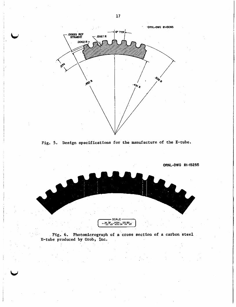
Fig. 5 . Design specifications for the manufacture of the E-tube.
ORNL-DWG 8445255
Fig. 6 . Photomicrograph of a cross section of a carbon steel E-tube produced by Grob, Tnc.


R- 3 n
6. EXPERIMENTAL WORK AT ORNL
experiments a t ORNL by S. K. Combs, G. S. MaLen and
R. W. Murphy’’ i n condensing re f r igerants on a var ie ty of vertical 25-mm (1.0-in.) diam f lu ted tubes have provided enough data t o make optimizations and predictions of heat transfer.
t o e s t ab l i sh the condensing f i lm coeff ic ient on the tube w a l l as a function of the heat f lux.
They used Wilson p lo t s
Combs et a1 made tests on a var ie ty of external surfaces on 2 h
diam tubes having heat t ransfer areas up t o 3.2 times (J-tube) the area of the smooth tube of equal length.
and R-600a (isobutane) re f r igerants were condensed on the cubes by them
t o obtain the experimental data.
the most promising tube was the aluminum E-tube, which provided mre condensate per un i t length than any of the others for condensing
isobutane.
R-11, R-21, R-22, R-113, E-114, R-115,
From this data it was concluded tha t
A comparison of the charac te r i s t ics of the standard A-tube, the
gear-shaped E-tube, and the flute-shaped F-tube are shown i n Table 1. It w i l l be noted t h a t the r a t i o of i n t e rna l t o external heat t ransfer
area is the grea tes t f o r the E-tube.
propert ies of each of the refr igerants .
e r an t s on a l l of the’tubes.
condensing R-11 on tubes with drainage s k i r t s spaced at 0.15s 0.30, 0.61,
1.22 m (6, 12, 24, and 48 In.).
ment f ac to r s
Table 2 shows the per t lnenr
The test by Combs e t a1 did not include condensfng each of che re f r ig-
Additional da ta were provided on rhe F-tube in
To try to co r re l a t e t h i s data , enhance-
e calculated comparing condensing film coef f ic ien ts
ubes with the condensing f i lm coef f ic ien ts f o r a smooth
e comparisons were made f o r various heat fluxes.
the enhancement fac tors as a function of hear flux t h various s k i r t spacings f o r tbe F-tube compared
w i t h a 1.22-111 E-tube with no skirts. 6300 W/m2 (2000 Btu/h-ft2), it w i l l be noted t h a t t he E-tube with
s k i r t s spaced 1.22 m apar t has about the same enhancement as the F-tube
with s k i r t s spaced 0.15 m apart. The maximum erihancement obtained w i t h
A t low heat f luxes [around
is’
19

c
Table 1. Characteristics of A-, E-, and P-tubes
Ratio Number of Flute diameter Inside diameter External area flutes Tube type Configuration
CUI in. Cm in. m2/m ft2/ft Ao/Ai
A Smboth 2.540 1.000 2,261 0.870 0.0243 0.2618 1.1494 0 B Geaw 2.565 1.010 2.189 0.862 0.0391 0.4208 1.8647 60 F Sine wave 2.540 1.000 2.286 0.900 0.0258 0.2775 1.1777 48
Table 2. Comparison of refrigerant properties at 311 K (100'F)
Property Units R-11 R-21 R-22 R-113 R-114 R-115 R-600a R-917 820
Saturation pressure
Thermal conductivity
Dynamic
Density viscosity
Heat of
Heat
Surface
cost
vaporization
capac i t y
tens ion
psia W a Btu/h*ft.*F w/m* K 1bIft.h Pa-8 x 10⁴ lb/ft3
Btullb
Btu/lb*OF J/(kg*K) lblft N/m US $/lb us S/ks
kstm3
J/kg x 10-5
23.46 0.1618 0.049 0.084 0.894 3.700 90.20 1445 .O
75.20 1.749 0.210 895.0 0.00114 0.0167 0.470 1.034
40.04 0.2761 0.056 0.097 0.690 2.840 83.40 1335.0 95.10 2.211 0.260 1090.0 0.00112 0.0163 0.540 1.188
210.6 1.452 0.047 0.082 0.440 1.840 71.20 1141.0 72.80 1.693 0.310 1310.0 0.00044 0.0065 0.870 1.914
10.48 0.073 0.042 0.073 1.380 5.700 95.80 1534.0 64.50 1.498 0.230 971.0 0.00117 0.0171 0.720 1.584
45.85 0.3161 0.035 0.061 0.710 2.900 88.40 1416.0 52.90 1.230 0.250 1040.0 0.00072 0.0171 0.810 1.782
182.73 1.260 0.027 0.046. 0.400 1.650 76.00 1217.0 35.60 0.832 0.300 1259.0 0.00026 0.0105 0.750 3.850
72.04 0.4967 0.059 0.102 0.350 1.450 33.40 535.0 133.1 3.094 0.630 2623.0 0.00057 0.0084 1.000 2.200
212.0 1.461 0.261 0.452 0.300 1.230 36.40 583.1 477.8 11.10 1.160 4845 .O
0.00120 0.0175 0.250 0.550
0.95 0.007 0.363 0.628 1.580 6.530 62.00 993.2 1037.0 24.10 1,000 4175.0 0.00480 0.0699 0.010 0.022

21
Fig. 7. Enhancement factors for condensing R-115 on E- and F-tubes compared with smooth tubes with no drainage skirts as functions of heat flux.
R-115 is aobut 3.75. at low heat fluxes with an increase in enhancement of about 1.6; at high fluxes the increase is reduced to 1.3.
The skirt spacing with R-115 seems more effective
Flgure 8 shows the same .relationships when condensing R-113 refrigerant where the maxiiuum enhancement is 6.75 with the 0.15-m skirt spacing on the F-tubes. could achieve about the same enhancement as the F-tubes with 0.15-m spacing. by a factor of 1.5 at l o w fluxes to 2.7 at the high fluxes by reducing the skirt spacing from 1.22 m to 0.15 m.
An E-tube with skirt spaced at 1.22- intervals
The enhancement in the condensing film coefficient is increased
Figure 9 shows the relationships when condensing R-11 vapor, which yields enhancement factors ‘as high as 8.0 by using 0.15-m skirt spacing. .fie effect of skirt spacing is not quite as sensitive here, with the

Fig. 8. Enhancement fac tors f o r condensing R-113 on E- and F-tubes compared with smooth tubes with no drainage s k i r t s as functions of heat flux.
Fig. 9. Enhancement f ac to r s fo r condensing R-11 on E- and F-tubes with smooth tubes with no drainage skirts as functions of heat flux.
23
increase ranging from 1.43 to 2.11 when decreasing the skirt spacing from 1.22 m to 0.15 m. about the same enhancement as the F-tube with the same spacing.
b, The E-tube with 1.22-m skirt spacing produces
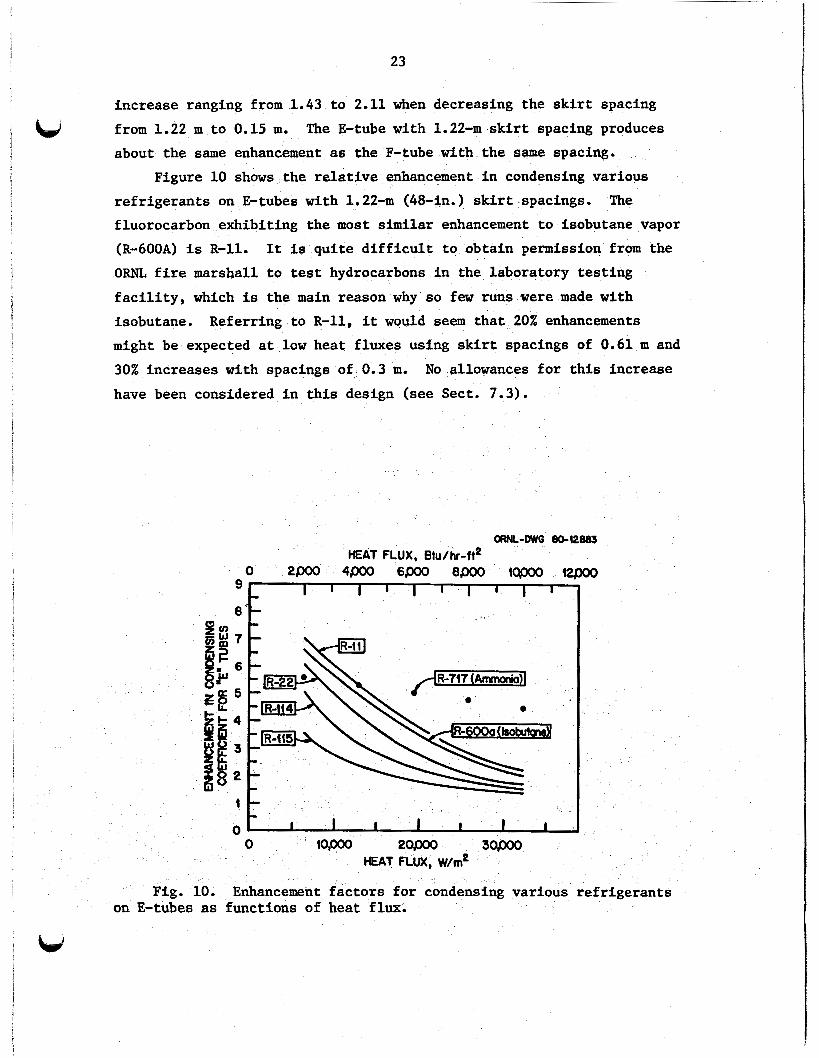
Figure 10 shows the relative enhancement in condensing various refrigerants on E-tubes with 1.22-m (48-in.) skirt spacings. fluorocarbon exhibiting the most similar enhancement to isobutane vapor (R-6OOA) is R-11. ORNL fire marshal1 t o test hydrocarbons in the laboratory testing facility, which is the main reason why so few runs were made with isobutane. Referring to R-11, it would seem that 20% enhancements might be expected at low heat fluxes using skirt spacings of 0.61 m and 30% increases with spacings of 0.3 m. have been considered in this design (see Sect. 7.3).
The
It is quite difficult to obtain permission from the
No allowances for this increase
ORNL-Dwo 6042883 HEAT FLUX, Btulhr-ft2
9 I I I I I I I I I I
Fig. 10. Enhancement factors for condensing various refrigerants on E-tubes as functions of heat flux.

24
Figure 11 shows the condensing heat transfer coefficient as a function of effective tube length for several tube types for high and low heat fluxes as given in Ref. 20. Several trends can be seen from this figure. It appears that increases in effective tube length reduce the condensing heat transfer coefficient more drastically, particularly at low fluxes, for the smooth tube than it does for an equal length increase in the fluted tubes. The condensing coefficients in most cases seem t o be reduced more at high heat fluxes than at low heat fluxes for fluted tubes.
Figure 12 shows the effect of tube length on the condensing coefficients on an F-tube for several selected refrigerants. It can be seen that the length has practically no effect at low heat fluxes
of 9500 W/m2 (3000 Btu/h-ft2) when condensing ammonia (R-717) and only a
slight effect at high heat fluxes of 28,000 W/m2 (9000 Btu/h-ft2). From review of all of the relationships pertaining to the effect of condensa- tion length on enhancement at low fluxes, it might generally be said that increasing tube length from 0.15 m (6 in.) to 1.22 m (48 in.) roughly decreases the condensing heat transfer coefficient by as much as 15%. 0.3 m (12 in.) results in increasing the total heat transfer by 5 to 10%. Conversely, increasing the length from 1.22 m (4 ft) to 4.88 m (16 ft) could conceivably decrease the overall heat transfer by a similar amount.
The net result of decreasing the tube length from 1.22 m to
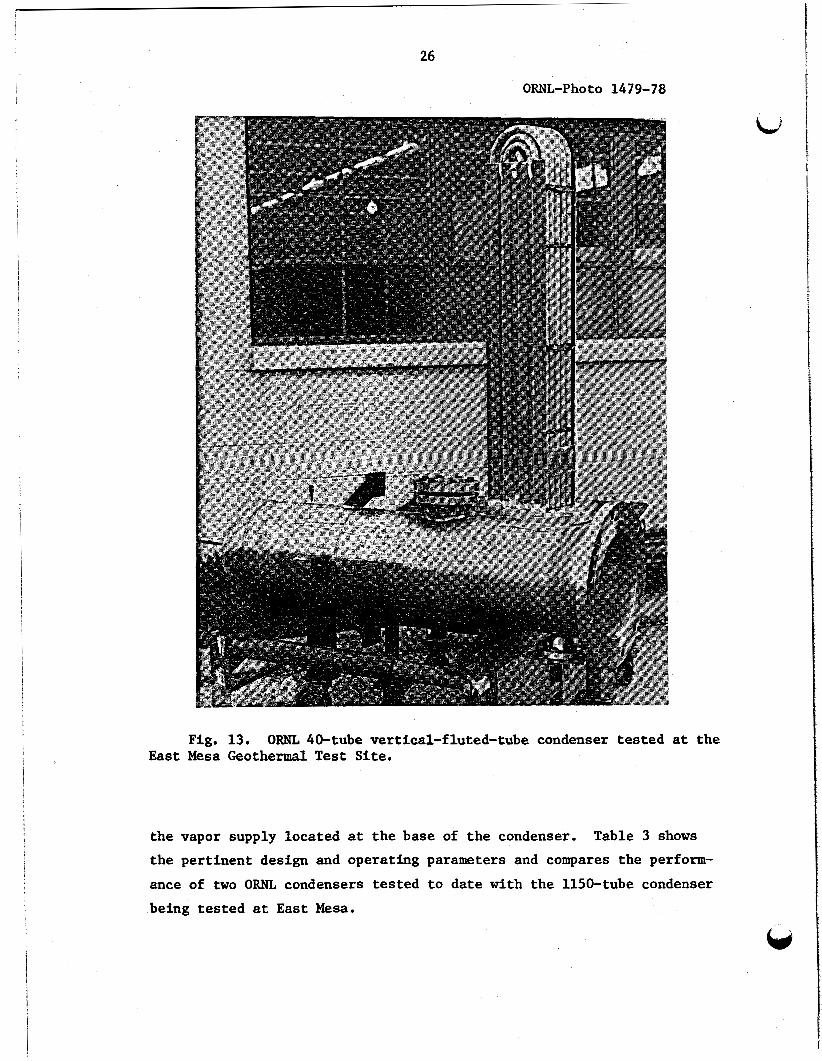
Before the design of the 1150-tube unit, a 4.2-m2 (45-ft2) 40-tube condenser was designed and tested by ORNL at the East Mesa facility.21 The 40-tube condenser shown in Fig. 13 contains aluminum F-type fluted tubes. The 25-mm (1.0 in.) F-tube has 48 flutes on the outside that resemble a sine wave having amplitudes of about 0.25 mm (10 mils). field test results of the 40-tube condenser indicated an overall heat transfer of less than one-fourth of the anticipated vlaues for the larger East Mesa condenser currently being investigated.
The
Tests were also made on a 104-vertical-fluted-tube condenser shown in Fig. 14 that was tested at the Geothermal Test Facility located at Raft River, Idaho. of this condenser, which performed considerably better than the 40-tube unit tested at East Mesa. It will be noted that the 104-tube unit has
A separate report is being prepared on the testing

25
auc2ap .O-.lSH
EFFECTIVE TUBE LENGTH Ill) as to 2.0 4.0
0.15 Q6 4.2 EFFE LENGTH W
Fig. 11. Effect of length on condensation coefficients F- and A-tubes at heat fluxes from 9450 to 28,000 W/m2 (3000 9000 Btu/h*ft2)
a45 0.3 0.6 1.2 EFFECTM W E LENGlHh)
of R-11 on to
Fig. 12. Effect of length of F-tube on the condensing coefficient for various vapors at different heat fluxes.
26
ORNL-P ho to 1479- 78
Fig. 13. ORNL 40-tube vertical-fluted-tube condenser tested at the East Mesa Geothermal Test Site.
the vapor supply located at the base of the condenser. the pertinent design and operating parameters and compares the perform- ance of two ORNL condensers tested to date with the 1150-tube condenser being tested at East Mesa.
Table 3 shows

y" VEWT 1
I 12' COOLING WATER SUPPLY
COOLER CONDENSER 'ps
6776 mm
27 2 - , -
ORNL-DWG 80-fO760R
PUS
TUBESHEET
q 2 " lRESSURE RELIEF
-BAFFLE
104 FLUTED TUBES 4 PASS CONFIGURATIOII
/,.On 0.0. 1 .04$ W U
/TUBE SUPPORT
/(SCH 40 I I P I )
/ M P I N G E M E N T BAFFLE
a<-/ /OOWNCOMEAS
Fig. 14. ORNL 104-tube vertical-fluted tube condenser. tested at the Raft River Geothermal Test Site.
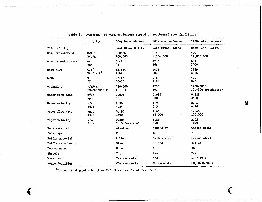
Table 3. Comparison of ORNL condensers tested at geothermal test facilities
Units 40-tube condenser 104-tube condenser 1150-tube condenser
Test facility Heat transferred
Heat transfer area'
Heat flux
LMTD
Overall U
Water flow rate
Water velocity
Vapor flow rate
Vapor velocity
Tube material Tube type Baffle material Baffle attachment Downcomers Shrouds Water vapor Noncondensibles
M W t ) Btu/h m2 f t2 W/m2 Btu/h* f t2 K OF W/m2*K Btu/h*ft2*'F m3/s
m/ s ftls
kg/s
ml S ft/s
gpm
lb/h
East Mesa, Calif. Raft River, Idaho 0.0586 200,000 4.46 48 13,134 4167 2 2- 28 40-50 450-600 80-105 0.006 90 1.38 4.54 0.190 1500 0.806 2.65 (maximum) Aluminum F
Rubber Glued None Yes Yes (amount?) C02 (amount?)
0.5 1,706,500 52.6 566 9471 3005 4.26 7.66 2205 392 0.019 300 1.98 5.5 1.65 13,000 1.83 6.0 Admiralty E Carbon steel Rolled 6 Yes Yes Np (amount?)
East Mesa, Calif. 5.0 17,065,000 688 7400 7269 2306 4.6 8.2 1700-2800 300-500 (predicted) 0.221 3500 2.04 6.70 12.63 100,000 3.05 10.0 Carbon steel E Carbon steel Rolled 38 Yes 1.37 wt X
C02 0.16 wt X
%iscounts plugged tube (2 at Raft River and 12 at East Mesa).
t

29
The values quoted on the smaller units are thoge involving the highest overall heat transfer coefficients in a direct-contact binary cycle. For complete details on the testing of these units, the reader is referred to forthcoming reports on the individual tests.
csd
There are several differences in these condensers that are worth mentioning. while at Raft River it is nitrogen. The 1150-tube unit contains the more efficient E-tubes having 60 flutes, about 1.5 times the coolant velocity of the 40-tube unit. The 1150-tube unit maintains a fairly constant vapor velocity on the shellside, which is about twice the maximum velocity as obtained in the 40-tube unit. 40-tube unit were fabricated from 0.38-mm (15-mi.l) resilient rubber, whereas the baffles of the larger unit are fabricated from 9 . 5 - m
(3/8-in. )-thick carbon steel plates into which the tubes are rolled. The latter arrangement provides a more stable flow path for the vapor
The noncondensable gas at East Mesa is carbon dioxide,
The baffles in the
and promotes more predictable uniform velocities.
,


6.i
7. HEAT TRANSFER CALCULATIONS
The heat transfer calculations for the condenser involve the physical properties of the liquid and vapor phases of the shellside fluid, the physical properties of the liquid phase of the tubeside fluid, and the thermodynamic properties of the shellside fluid. total heat transfer is obtained by calculation of the tubeside heat transfer coefficient, and estimation of the tubeside and shellside fouling factors. The design area of the condenser is obtained from a combination of experimental and calculated data (along with some
The
educated guesses). have been correlated and computerized using a Gibbs-type phase rule for selecting the equations and variables for sizing the condenser.
The heat transfer and pressure drop relationships
7.1 Properties of Liquid and Vapor Streams
The determination of the heat content of the vapor streams can present problems in evaluating the condenser performance. vapor composition might contain several light hydrocarbons, water, and some noncondensable gases.
The actual
The Benedict-Webb-Rubin (BWR) , Hans-Starling (HS) , Redlich-Kwong (RK) and Peng-Robinson (PR) equations of state are all popular contenders for accurate means of determining the thermodynamic properties of hydro- carbon vapors. N. A. Samurin and J. R. Shields22 of the Elliott Company have compared the BWR, PR, and HS equations with General Electric's Mark V proprietary computer code. The HS correlation was found to predict lower saturation temperatures at pressures below 500 psia, and as much as 5% difference was noted in the saturation temperature at 50 psia.
The HS equations were used by the system designers of East Mesa for evaluating the thermodynamic properties of gases for the 500-kW(e) system now operational at the geothermal test site. properties o ight hydrocarb and gases using the Starling-Benedict- Webb-Rubin c Because of its polarity, water was not included.
Thermodynamic
elation were compiled and computereized by K. E. Starling.23
U 31

32
The desired ana ly t ica l scheme is t o evaluate the vapor-liquid
equilibrium constants from the fugac i t ies and ul t imately t o predict a
bubble point and dew point as a function of pressure (and locat ion)
i n the exchanger. The s i tua t ion is fur ther complicated f o r a mixed
hydrocarbon vapor containing both i d s c i b l e s and noncondensables.
D. H. Riemer et al.24 of the University of Utah have a l s o compiled
a program using the Starling-Benedict-Webb-Rubin corre la t ion t o evaluate the pure component thermodynamic propert ies Qf 12 l i g h t hydrocarbons.
Eventually, we would l i k e t o use S tar l ings computerized data t h a t
have been expanded t o allow f o r water composition as a subroutine f o r
obtaining thermodynamic propert ies of the mixtures.
Physical and thermodynamic property data f o r isobutane over the
per t inent temperature and pressure range are shown i n Appendix B. data were obtained from the American I n s t i t u t e of Petroleum Engineers (API)
Data Book25.
These
Figures B . l through Fig. B.3 show the l a t e n t heat , vapor
pressure, and spec i f i c heat as functions of temperature.
shows the enthalpy as a function of both temperature and pressure.
Figure B.5 shows the s o l u b i l i t y of both propane and isobutane i n water as
functions of temperature, and Fig. B.6 shows the s o l u b i l i t y of both
propane and and isobutane as functions of temperature. Appendix C shows
the physical propert ies of water used i n the tubeside heat t r ans fe r cor-
r e l a t ions tabulated over the appropriate temperature range. These data
can be used f o r making quick checks on the cor re la t ions employed i n the
design.
Figure B.4
7.2 Tubeside Heat Transfer Coefficient
The condenser design is based on the a v a i l a b i l i t y of 0.22 m 3 / s
(3500 gpm) of cooling water supplied a t temperatures ranging from
282 t o 300K (50 t o 80°F). the E-tubes i s su f f i c i en t t o produce turbulent flow with a resu l t ing
tubeside heat t r ans fe r coef f ic ien t of about 570 W/m2*K (100 Btu/h*ft**OF) , but it takes a veloci ty of 2.7 m 3 / s (8.9 f t / s ) t o obtain a heat t ransfer
coef f ic ien t of 9080 W/m2*K (1600 Btu/h*ft2*OF) based on the D i t t u s -
Boelter correlat ion.
A tubeside veloci ty 0.09 m / s (0.3 f t / s ) i n
i u i

33
According to Kays and Perkins,26 the most applicable equations for
w calculating turbulent flow inside smooth tubes are the Dittus-Boelter, Colburn, and the Sieder-Tate correlations.
The Dittus-Boelter correlation shown in Eq. (1) defines the Nusselt number, Nu, for heating fluids in circular tubes and is recommended when there is less than a 5.6K (10'F) drop across the water film:
Nu = 0.023 Reoo8 Proo4 = h*D/k (1)
Equation (1) is based on extensive experimental data covering ranges in Reynold numbers from 10,000 to 120,000, Prandtl numbers from 0.7 to 120, and for L/D ratios greater than 60. final condenser design is about 45,000, the Prandtl is about 6.8, and the L/D ratio is over 225. to be evaluated at the mean bulk-fluid temperature. correlation defines the Nusselt number for both heating and cooling of fluids in circular tubes as shown in Eq. (2)
The Reynolds number in the
The physical properties used in Eq. (1) are The Colburn
Nu = 0.023 Reoo8 Pr1i3 = St-ProRe = h*D/k (2)
and extends the correlation to include the j-factor defined in several ways in Eq. (3) :
j = St Pr2i3 = 0.023 R e - O o 2 = f/8 (3)
In the Colburn correlation, it is recommended that the physical properties be evaluated at the mean temperature between the average bulk-fluid tem- perature and the average tube-wall surface temperature. also provides a method of evaluating the friction factor used in the determination of the pressure drop.
This correlation
The Sieder-Tate correlation as shown in Eq. (4) allows for radial
variations in the viscosity. the tubeside heat transfer coefficient when the fluid is being heated and decrease it when the fluid is being cooled.
The viscosity ratio term tends to increase
Nu = 0.027 Reoo8 Proo4 (u/us)0*14 = h*D/k (4)

34
L An approximate heat transfer coef f i ~ i e n t ~ ~ for the turbulent flow of water inside tubes in the temperature range of 5 to 104K (40 to 220'F) /
is shown in Eq. (5) and depends only on the size of the conduit, the velocity, and temperature.
h = C (1 + O.Olltb) Vf=8/Do*2 1
where in Eqs. (1 through 5)
Nu = dimensionless Nusselt number = h-D/k, Pr = dimensionless Prandtl number = Cpp/k, Re = dimensionless Reynolds number = DG/p, St = dimensionless Staunton number = h/C *G = Nu/Re-Pr,
P h = tubside heat transfer coefficient , W/m2-K(Btu/h*f t2* OF), D = inside tube diameter, m(ft), D1 = inside tube diameter, inches, k = thermal conductivity of fluid evaluated at tb, W/m*K(Btu/h-ft-OF),
C = specific heat evaluated at-t J/kg*K(Btu/lbmoF), P by l.i = dynamic viscosity evaluated at tb, Pas(lb/ft*h) ,
ps = dynamic viscosity evaluated at t Pas(lb/ft*h) , f = dimensionless Darcy-Weisbach friction factor,
S'
= inside the tube wall temperature, K('F), tW
tS
tb = bulk fluid temperature, K('F), = average film temperature = 0.5 (tw + t,), K('F),
G = coolant mass velocity = Vp kg/m2s, 3600 Vp lb/ft2h, V = fluid velocity m/s (ft/h), V1 = fluid velocity, ft/s,
p = fluid density evaluted at tb, kg/m3 (lb/ft3), j = dimensionaless Colburn j-factor, C = 851.25 for metric units, 150 for English units,
Changes in the coolant supply temperature of a5.6K (lO°F) will cause a corresponding change from 6 to 9% in calculating the heat transfer coefficients in any of the above equations. the coolant supply is running hot, the tubeside coefficient will be
In midsummer when
di
,

u 1 I 1
35
higher, but so will the condensing pressure and consequently the temperature of the isobutane because it is close to the temperature of the condensing surface. coefficient will result in a slight decrease in the rise in the bulk water temperature and the log mean temperature difference. in the condensing temperature being slightly below the temperature that would have resulted if the thermal effect on the coefficient had not been considered.
The small increase in overall heat transfer
This results
The relationships for the four correlations for the inside heat transfer coefficient are plotted as functions of coolant flow rate at a temperature of 300K (80'F) in Fig. 15. variations caused by temperature changes for each correlation. Equation (1) was used to calculate the tubeside heat transfer coefficient, and it is assumed to be accurate within 1 to 2%.
The relationships indicate
5Ooo a8 a9 0.20 0.2 4 022 023
FLOW RATE, m3/s
Fig. 15. Comparison of tubeside heat transfer correlations in East Mesa condenser for turbulent flow as functions of flow rate at 300 K (80'F).

36
At a constant wall heat flux, the thermal entry length was investigated for a Reynold number of 45,000 and a Prandtl of 6 . 0 ; it takes about 6 tube diameters (0.13 m or 5 in.) to obtain fully developed thermal flow. an entry length of about 30 tube diameters (0.66 m or 26 in.) is required. ratio of 237, no allowance was made for the differences in the regime of developing flow.
To obtain fully developed thermal and hydraulic flows,
These facts considered and knowing that the tube has an (L/D)
7 .3 Shellside Heat Transfer Coefficient
Equation ( 6 ) shows the Nusselt correlation for calculating the condensing coefficient on the outside of horizontal rows of smooth tubes :
Equation ( 7 ) shows the basic Nusselt correlation for calculating the condensing coefficient on the outside of a single vertical tube:
where
= vapor density, pV k = liquid thermal conductivity, p = liquid.density, hv = condensing coefficient on vertical tube, \ = condensing coefficient for n rows of horizontal tubes, X = latent heat of condensation (vaporization), g = acceleration due to gravity, ~ . l = dynamic viscosity,
( 7 )

37
Do = outside tube diameter, - sa tura t ion temperature of vapor, - w a l l temperature, tsat
tw I# = l o s s fac tor due t o inundation (Fig. 16), = f (number of rows
of tubes), N
R = hv/% = 1.30 (D/L)li4 4
Assuming an L/D of 24 f o r a s ing le tube, it would appear t ha t a
smooth vertical tube could condense only 60% of t he vapor t h a t could
be condensed on the same tube i n a horizontal posit ion.
c lose t o r e a l i t y for a s ing le tube.
incurred with a horizontal exchanger having as many as 100 tubes i n a v e r t i c a l row, the vertical un i t could condense t w i c e as much vapor.
Only ten rows of tubes are needed before equal condensation is expected
from both u n i t s based on I# using the Nusselt correlat ion. Increasing
the number of vertical tubes does not s ign i f i can t ly decrease the heat
t r ans fe r per tube. Shel ls ide condensation takes on fur ther complexities
when noncondensables and other components are added t o the vapor stream.
This is probably
I f we consider the inundation l o s s
1.4
1.2
I .o
0.8 8-
0.6
. 0.4
0.2
ORNL- OW0 81-9433 I I I I I I l l 1
I I I 1 I I l l 1 I I I I I I I 0 I 10 KK)
N-NUMBER OF TUBES IN A VERTICAL ROW
Fig. 16. Inundation correction fac tor for s ing le smooth tube horizontal condensers as a function of the number of v e r t i c a l rows.

38
There are concentration gradients and temperature gradients as functions of distance through the condenser in the shellside condensa- tion of a multicomponent mixture. The higher boiling components will condense out first and in higher concentrations in the condensate and lower concentration in the vapor/gas mixture. The lower boiling com- ponents will come out further down the condenser.
Quantitatively, because of the diffusion and nonequilibrium involved, the analysis is extremely complex and seldom are there enough data, either experimental or theoretical, to warrant on exact analysis. The thermodynamics must supply the vapor-liquid equilibrium so that a dew- point and bubble point can be determined preferably at each row of tubes in the condenser. and usually are of a proprietary nature.
Computer codes are required for this purpose Both the Heat Transfer
Research Institute (HTRI) at Alhambra, California, and Heat Transfer and Fluid System (HTFS),28 Harwell, England, have computer codes for handling this type of problem. other proprietary codes using ternery mixtures with C02 present as a noncondensable.
We have tried, without success, several
The case when noncondensables are present in a pure component gas has presented problems since the first boiler went into operation. Othmer29 predicted in 1929 that in condensing steam, the condensing coefficient could be reduced by as much as 50% with as little as 1% noncondensable (air) present in the steam. stagnant steam was being condensed on 0.23-m (9-in.) diameter tubes, this was quite true. shear becomes involved, not only would the presence of 1% noncondensable go unnoticed, but there also would be a remarkable increase in the overall heat transfer due to the vapor shear.
From his experiments where
When the vapor is moving at high velocities and vapor-
In a recent article F. C. Standiford30 demonstrated the effects of
noncondensables at velocities ranging from 0.2 to 2 m/s (1 to 7 ft/s) are not nearly as severe: a 5% reduction in the "air free" coefficient (Fig. 17). effect appears to be a function of the condenser design. of information indicate that the effect of a noncondensable is also
more like 10% air at the vent point causing However, this Other sources

39
B L 70
s z 0
W
W a 60
- -
- - I I I I I I
proportional to the ratio of the densities or the molecular weights of the noncondensable to the condensable vapor. for a noncondensable in the presence of a single condensable is the Colburn-Houghton3 method.
"he standard treatment
Collections of subroutines have been gathered by G . R. E. Franks3* that give the designer the capability of performing a row-by-row analysis for shellside condensation. calculation of the shellside condensing coefficinet for multicomponent vapor with noncondensables without considering the presence of water and vapor shear.
epth treatment of this subject has been covered by John Prausnitz et a1.,33 that allows the thermodynamic contribution of water to be evaluated realistically while also considering vapor shear that produces much higher condensing heat transfer coefficients.
Franks presented a method of
A more recent
The overall heat transfer is calculated in the same manner regard- less of how the shellside condensing coefficient is evaluated, so rather

40
than calculating or even estimating the effect of these variables, it would seem to be wiser to use the experimental results obtained for the 1.22-m (4-ft) E-tube with no skirts. This approach is believed to be conservative. No credit is taken in the East Mesa condenser design for vapor shear or the fact that the skirt spacing on the condenser is 0.61 m (2 ft) or less. Allowance was not made in the East Mesa con- denser design for the presence of noncondensable in the vapor stream, but previous assumptions should more than compensate for this omission.
It is planned eventually to correlate the data from these experi- ments into basic equations for calculating the shellside heat transfer coefficient. This shellside correlation might ultimately involve con- sideration of the composition, quality, and velocity of the vapor, the temperature of the condensing surface, and the tube configuration. To develop shellside correlations, some degree of precision must be maintained in the experiments in the evaluation of the LMTD and the inside heat transfer coefficient; the heat flux is easier to evaluate.
For the evaluation of the shellside condensing coefficient for the East Mesa condenser, single tube experimental data are used that were gather by Combs et al., in condensing isobutane on a 1.22- (4-ft) long aluminium E-tube.19 Similar data were acquired by N. Doming0 of ORNL in condensing R-11 on both 1.22-m (4-ft) long carbon steel and aluminu~n~~ E-tube. The data (Fig. 18), obtained from Wilson plots and including the wall resistance, were fitted to polynomial expressions for use in the computer programs.
7.4 Fouling
C. H. G i l m ~ r e ~ ~ of Union Carbide has claimed that fouling can be reduced to practically nothing when tubes are chrome plated internally and externally and the velocities are kept high.
The tubeside fouling estimation for the East Mesa condenser was based on several factors. The tube material was low-carbon steel with a carbon content of less than 0.10%, almost like Swedish steel. The coolant is treated, recirculated water-that is to be totally contained within the

41
64'
6ooo
5000
4000
3000
2000
1000
OWL-DWG 81-22624
HEAT FLUX (Btulhr ft' O F )
0 2,000 4,000 6,000 8POO !OW 12,000
o ALUM. E-TUBE (R-6000) A CAR. STL. E-TUBE (R-11) 0
e 0 ALUM. E-TUBE (R-ll) t 0
I- :". 1
600
400
200
c
0 40,000 20,000 34000
HEAT FLUX (W/rnZ)
Fig. 18. Experimental shellside condensing coefficients obtained for E-tubes.
pipes and never comes in contact with any geothermal brines. velocity is relatively high at about 2.1 m/s (7 ft/s). pated fouling from treated cooling tower water is 0.00018 m2*K/w (0.001 h*ft2*OF/Btu) and for design purposes 2/3 of this value will be used, or 0.00012 m2*K/W (0.00066 h*ft2-'F/Btu). multiplied by the ratio of the outside to inside heat transfer area of 1.85.
The water Maximum antici-
_ _ This value has to be
-
The maximum shellside fouling for clean hydrocarbons is taken as 0,00009 m2-K/w (0.0005 h-f t2-OF/Btu); 50% of this value or 0.000045 m2-K/w (0.00025 h*ft2*OF/Btu) will be used for the design value.

42
A total fouling factor of 0.000259 m2*K/W (0.00147 h*ft2*'F/Btu) is then used in calculating the area requirements for the East Mesa condenser. and Kern37 and are used by most heat exchanger manufacturers.
The above mentioned fouling factors are referenced in TEMA36
7.5 Overall Heat Transfer Coefficient
The overall heat transfer coefficient may be calculated by the summation of all the component resistances with corrections for the ratios of the heat transfer area. ductances are additive and series resistances are additive as shown by combining the five component resistances in series in Eq. (9)
As in electrical flow, parallel con-
where
= the overall heat transfer coefficient W/m2-K (Btu/h* f t2* OF), = outside area of tube, m2 (ft2),
uO
AO Ai = inside area of tube, m2 (ft2),
Am hi = tubeside heat transfer coefficient W/m2*K (Btu/h*ft2*OF), fi = tubeside fouling factor m2*K/W (h*ft2e0F/Btu), h
= log-mean average tube area, m2 (f t2) ,
= shellside heat transfer coefficient W/m2*K (Btu/h*ft2.OF), = shellside fouling factor m2-K/W (h*ft2*'F/Btu),
0
fO k = thermal conductivity of tube material W/m*K (Btu/h*ft*OF), L = tube wall thickness m (ft).
Because the experimental data used to obtain the condensing coef- ficient was done using the Wilson plot, which includes the wall resist- ance of the tube, the last term in Eq. (9) will be deleted in the calculation. (Ao/Ai), is 1.850.
In discussing the enhancement of the fluted tube, it should be pointed out that if the tubeside resistance is controlling, improvement
The ratio of the outside to inside area of the E-tube,

43
in the overall heat transfer is not as apparent with improvement in the shellside coefficient. rate of 3500 gpm and a fouling factor of 0.0012 m2*K/W, (0,00066 h.ft2.'F/Btu) results in a total tubeside resistance of 0.000296 m2*K/W (0.001681 h*ft2*'F/Btu) When fouling is neglected, the tubeside resistance is reduced to 0.000233 m2*K/W (0.001324 h*ft2*'F/Btu). total shellside resistance which includes the wall resistance could vary from a minimum of 0.000185 m2*K/W (0.000883 h*ft2*OF/Btu) to a maximum of 0.000230 m2*K/W (0.001303 h*ft2*OF/Btu. A plot of the overall heat transfer coefficient as a function of the condensing coefficient with and without anticipated fouling is shown in Figure 19. noticed that the shellside resistance is controlling up to a shellside coefficient of 3900 W/m2*K (687 Btu/h-ft2.'F) at a constant coolant flow rate of 0.2 m3/s (3500 gpm).
For the case at hand, the coolant flow
The
It will be
Several facts can be deduced from this plot. (1) Fouling is more
devastating to enhanced exchangers than unenhanced exchangers. (2) Enhancement is more apparent when the film on the enhanced surface is not the controlling resistance. (3) To make the shellside resistance
ORNL-WG 81-19668 SHELLSIDE CONDENSING COEFFICIENT
Btu/hr ft2 O F 200 300 400 500 600 700 800 900 1ooo I100 1200
700
600 p k RESISTANCE CONTROLLING 5008
6': 32
W E 2 I -G
TUBESIDE t
400 &m!
4
DESIGN FOULING 200 Y
100
0
SHELLSIDE RESISTANCE CONTROLLING
2000 3000 4000 5000 6000 SHELLSIDE CONDENSING COEFFICIENT
W/m2 K
Fig. 19. Overall heat transfer coefficient as a function of the condensing coefficient for the East Mesa condenser at a coolant flow rate of 0.22 m3/s (3500 gpm)

44
controlling requires increasing the tubeside velocity, which is quite costly, with the pumping cost being proportional to the cube of coolant flow rate. anticipated condensing coefficient of 5820 W/m2*K (1025 Btu/h*ft2*'F) a coolant flow rate of 0.322 m3/a (5100 gpm) would be required.
To achieve a controlling resistance with a maximum
Fouling can often be reduced by the proper selection of tube material, addition of inhibitors to the coolant, and periodic cleaning of the tubes. the pumping capacity of the tubeside coolant. can be reduced by limiting the noncondensables in the condenser, but insufficient condensation of the shellside vapor in a given condenser is rarely improved by increasing the flow rate of the vapor. of the East Mesa condenser, a coolant flow rate of 0.322 m3/s would
The tubeside resistance can be reduced by increasing The shellside resistance
In the case
require a 303-hp pump requiring 0.283 Mw of power, which is 57% of the total power produced by the turbo generator.
7.6 Log Mean Temperature Difference
The log mean temperature difference (LJITD) for a counter-current or cocurrent liquid-liquid heat exchanger is calculated in a straight forward manner. entering the exchanger at a temperature t
Consider cold fluid on the tubeside of a heat exchanger and leaving at a temperature i
Hot fluid is on the shellside entering at a temperature T leaving at To. and the average temperature of the cold stream is (to + ti)/2. average temperature difference between these two streams is the sums of the two streams (To + Ti)/2 - (ti + to)/2 regardless of whether the flow is cocurrent or counter-current. The LMTD between these streams is defined for counter-current flow in Eq. (10) :
and i The average temperature of the hot stream is (T + Ti)/2,
0
The
LMTD = (Ti - to) - (To - ti)/ln (Ti - to)-/(To - ti) . (10)

45 .
If the flow is cocurrent the W D is calculated as shown in Eq. (ll), bd
Assuming a constant condensing temperature of 307.4K (94OF), a
water supply temperature of 299.7K (80°F), and a water flow rate of 0.221 m3/s (3500 gpm), the rise in the coolant: temperature is 5.44K (9.79'F) . streams of about 5K (9OF) both the counter-current and cocurrent LMTD is 4.55K (8.1g°F), a difference of lo%, which could mean $3700 in tubing cost. The four-tube-pass configuration for condensation is both
With an average temperature difference between the two
counter-current and cocurrent, depending on the pass. tions have been made on calculation of LMTD for multipass liquid-liquid heat exchangers.
2.3K (4.2OF) and a small average temperature difference of 5K (9'F), it seems unwise to use correction factors correlated for liquid-liquid exchangers where the efficiency is either zero or infinite when a constant temperature is employed because the methods don't allow for heat transfer with a change of phase. the design. streams as a function of the length in the exchanger.
Many investiga-
Because we are dealing with a relatively small approach temperature
Therefore, 4.55K (8.19OF) LMTD w i l l be used for Figure 20 shows the temperature distributions in both
Some explanation should be given for this approach3* because some designers still break the condenser into component parts. heating, condensing, and subcooling sections or regimes are often evaluated with corresponding heat transfer coefficients, W D s , and areas for each section. the area actually required. desuperheating being done is in the first half of the first pass across the tube bank.
Desuper-
This approach provides from two to five times In the East Mesa condenser, most of the
About 13% of the total heat is superheat. If the
desuperheating is based on a gas film coefficient of about 285 W/m2*K (50 Btu/h*ft2B0F), 520 m2 (5600 ft2) of heat transfer area is required, which is 72% of the design area of the East Mesa condenser, thus

46
333
Y 308
5 306 a E 304 302
300
0 0.5 FRACTION OF LENGTH
LO
Fig. 20. Tubeside and shellside temperature distribution as a function of length for the East Mesa condenser.
leaving insufficient area for condensing. Using this method of cal- culation would require a much larger condenser. Instead of the three stages happening separately, they actually occur simultaneously, with desuperheating requiring about the same percentage (13%) of the total surface area or 93 m2 (1000 ft*).
8. PRESSURE DROP CALCULATIONS
L4 When the flow rates are increased in a given condenser, there are usually noticeable increases in heat transfer and obviously correspond- ing increases in pressure drops. by the pumping head or the allowable pressure drops across the tubeside and shellside of the condenser. it must be compensated for by adding more heat ‘transfer area with a loss of efficiency because velocities must be reduced to avoid exceeding the allowable pressure drops. concept, most heat exchanger manufacturers will usually guarantee the heat transfer or the pressure drop but not both. to obtain reliable pressure drop correlations as it is to obtain reliable heat transfer correlations.
Generally the heat transfer is limited
If the pressure cannot be supplied,
When in doubt about an untested or new design
It is just as important
The tubeside pressure drops in the analysis of this condenser are relatively easy to calculate because we are dealing with a single- phase fluid in uniform channels. difficult to evaluate. shellside pressure drop involving a constantly changing flow area with the condensate being constantly removed.
The shellside pressure drops are more Two-phase flow is involved in evaluating the
8.1 Tubeside Pressure Drop
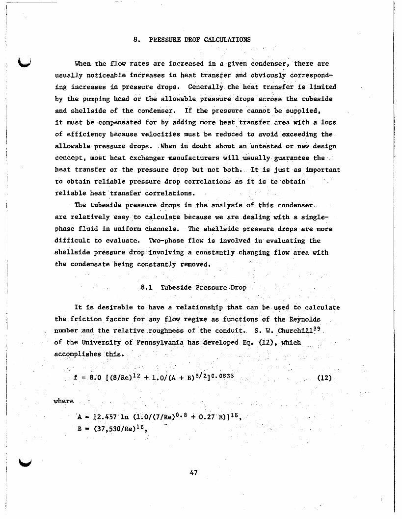
It is desirable to have a relationship that can be used to calculate the friction factor for any flow regime as functions of the Reynolds number and the relative roughness of the conduit. S. W. Ch~rchill~~ of the University of Pennsylvania has developed Eq. (12), which accomplishes
f = 8.0 [(8/Re)12 + l.O/(A + B) 3/21 0.0833 (12)
where
A = 12.457 In B = (37,530/Re)16,
1.0/(7/Re)0*8 + 0.27 E)]16,
47 u

48
Re = dimensionless Reynolds number,
E = surface roughness, m ( f t ) ,
= 1.52 x m ( 5 x f t ) f o r smooth tubing, D = ins ide tube diameter, m ( f t ) ,
f = dimensionless Darcy-Weisbach f r i c t i o n fac tor ,
E = dimensionless relative roughness = e/D.
Entrance l o s s f o r t he tubes w i l l vary from a minimum of zero f o r
spec ia l ly rounded openings t o 8 maximum of 1/2 ve loc i ty head, V2/4g.
be conservative, the maximum entrance l o s s has been assumed f o r design
purposes based on t h e coolant ve loc i ty i n the tubes.
To
The e x i t l o s s is expressed as one ve loc i ty head multiplied by
(l.O-At/As) where At is the tube area and As is the area of the discharge
section. The maximum l o s s is incurred as A becomes i n f i n i t e , so the
maximum l o s s is one ve loc i ty head o r V2/2g. This drop is independent
of t he shape of t he exit. There are four separate tube entrances and
four separate tube e x i t s t h a t must be accounted f o r i n ca lcu la t ing the
t o t a l tubeside drop.
S
There is a pressure lo s s each t i m e the f l u i d changes direct ion.
This l o s s can be evaluated by assuming a loss of one ve loc i ty head f o r
each 90' tu rn i n the f l u i d of a constant velocity.
When the coolant d i rec t ion is changed i n going from the entrance nozzle
i n t o the f i r s t tube pass with a flow area A i . Two turns are encountered
(180' turn) associated with area A2 i n going from the tubes i n the f i r s t
pass t o the tubes i n the second pass.
There is a turn
Two more turns are encountered
i n the header i n the center sect ion i n going from the second t o the
th i rd pass associated with an associated area A3.
encountered i n going from the t h i r d t o the fourth pass associated with
area A2.
f l u i d moves from the tubes in the fourth pass t o the coolant discharge
nozzle.
Two more turns are
Final ly , there i s one turn associated with area A1 when the
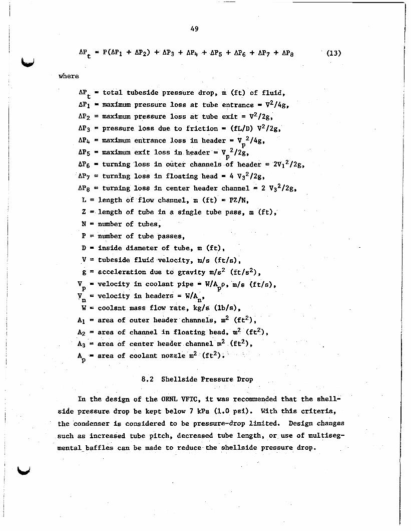
The t o t a l tubeside pressure drop, Apt, i n the condenser is obtained
by summation of t he component pressure drops as given i n Eq. (13) f o r
the mil t ipass configuration.
,
49
where
APt = t o t a l tubeside pressure drop, rn ( f t ) of f l u id ,
AP1 = maximum pressure l o s s a t tube entrance = V2/4g,
APp = maximum pressure l o s s a t tube e x i t = V2/2g,
AP3 = pressure l o s s due t o f r i c t i o n = (fL/D) V2/2g,
AP4 = maximum entrance l o s s i n header = V 2/4g,
AP5 = maximum e x i t loss i n header = V 2/2g,
AP6 = turning lo s s i n outer channels of header = 2V12/2g,
AP7 = t u r n h g l o s s i n f loa t ing head = 4 Vs2/2g,
APg = turning loss i n center header channel = 2 V32/2g,
P
P
L = length of flow channel, m ( f t ) = PZ/N,
2 = length of tube i n a s ing le tube pass, m ( f t ) ,
N = number of tubes,
P = number of tube passes,
D = ins ide diameter of tube, m ( f t ) ,
V = tubeside f l u i d velocity, m/s ( f t / s ) ,
g = accelerat ion due to gravity m/s2 ( f t / s 2 ) ,
P = veloc i ty i n headers = W/An,
W = coolant mass flow rate, kg/s ( lb/s) ,
V = veloc i ty i n coolant pipe = W/App, m/s ( f t / s ) ,
vn
A1 = area of outer header channels, m2 ( f t 2 ) ,
A2 -- area of channel i n f loa t ing head, m2 ( f t 2 ) ,
A3 = area of center header channel m2 ( f t 2 ) ,
A = area of coolant nozzle rn2 (&Is P
8.2 Shel ls ide Pressure Drop
I n the design of t h e ORNL VFTC, it was recommended t h a t the shel l -
s ide pressure drop be kept below 7 kPa (1.0 ps i ) . the condenser is considered t o be pressure-drop limited. Design changes
such as increased tube pi tch, decreased tube length, o r use of multiseg-
mental ba f f l e s can be made t o reduce the she l l s ide pressure drop.
With t h i s criteria,

50
F i r s t of a l l , i t w a s desirable t o obtain some idea of the allowable
baf f les assuming 15% ba f f l e cut with tubes i n the window and equal
ba f f l e spacing.
proposed by D. G. Kern,40 which uses one-half of t he pressure drop
calculated f o r the t o t a l flow of the vapor through the enture she l l .
With a vapor flow rate of 12.63 kg/s (100,000 lb/h) i t was found tha t
s i x equally spaced baf f les would cause a pressure drop of 5.9 kF’a
(0.9 ps i ) while seven baf f les resul ted i n a pressure drop of 8.9 kPa
(1.3 ps i ) , therefore exceeding the design requirements.
These relat ionships were found i n an empirical equation
Using s i x baff les , it w a s decided t o rearrange the spacing so tha t
an approach t o a uniform vapor veloci ty could be obtained through each
s h e l l pass. A computer program was wr i t ten t o make the task easier
by providing a row-by-row analysis of the pressure drop as shown i n
Appendix D.
The program requires knowledge of the number of tubes on each row,
the ba f f l e spacing a t each pass, the area of the segmental opening tha t
is void of tubes, and the m a s s flow rate of the vapor. It is assumed
t h a t the condensation is equally d is t r ibu ted over the t o t a l length of
tubes about 8.06 kg/m (5.40 l b / f t ) .
be conservative because of the superheat involved.
t ha t the superheat is probably dissipated i n the f i r s t half of the
f i r s t she l l s ide pass.
s l i g h t l y higher pressure drop i n the f i r s t pass, with the t o t a l she l l s ide
drop remaining about the same.
This assumption does not appear t o
It is estimated
This assumption would probably r e s u l t i n
The summation of the component pressure drops on the she l l s ide of
the condenser, APs, i s given i n Eq. (12)
where
APs = t o t a l she l l s ide pressure drop, m ( f t ) of f l u id ,
AP1 = maximum pressure l o s s i n concentric expansion from 12-in.
pipe, t o 24-in. pipe = K V12/2g,

is
51
VI = veloci ty i n 12-in. pipe, m/s ( f t / s ) ,
B2 = (d1/d2)~ = 0.2784,
K (1 - fi2)2 = 0.5207,
d l = ins ide diameter of 12-in. Sch 40 pipe, m ( f t ) ,
d2 = ins ide diameter of 244x1. Sch 40 pipe, m ( f t ) ,
Vp = veloci ty i n 24-in. pipe m/s ( fps) ,
AP2 = maximum entrance 10s t o condenser = 0.5 Vz2/2g,
g = accelerat ion due t o gravity m/s2 ( f t / s2 ) ,
AP3 = pressure l o s s due t o f l
and i t h pass having a f
f vapor through j t h row of tubes
area Aij = f i j v2 ij /2g,
A B (N + 1 ) (P - D), i j i J N = number of tubes on j t h row, j P = tube pi tch, m ( f t ) ,
D = 0.D of tube, m ( f t ) ,
Bi = baf f l e spacing f o r i t h pass m ( f t ) ,
i j
Re = dimensionless Reynolds numbe i J
- mass flow rate o f vapor a t i i j t h
13
f = dimensionless Darcy-Weisbach f r i c t i o n f ac to r =
0.8*Re - O o 2 evaluated at ith pass and jth row,
row = D Wij /uAi ,
$3 aluated a t ith pass and jth
W pass and jth
row = (Wi+l,j - Cij)/2, C
AP4 = pressure drop across ba f f l e windows
= mass f l o w of condensate condensed a t ith pass and jth row,
= 1 veloci ty head =
= veloc i ty a t ith pass and j t h row = Wij/pAij,
Vk = veloc i ty a t kth baf f l e = Wk/p%,
i j Wk = mass flow rate of vapor through kth baf f l e ,
% = b a f f l e area = 0.118 m2 (1.28 f t 2 ) ,
it = t o t a l number of tube passes = 6 (see Fig. 211,
j t = t o t a l number o f tube rows = 32,
k t = t o t a l number of flow reversals ( t u n s ) = i-1,
v
i = pass number,
j = row number,
k = t u rn number,
p = vapor density, kg/m3 ( lb / f t3 ) ,
p = vapor viscosi ty , Pa*s (lb/’ft*h).

ORNL-DWG 81-13094
I
@-BAFFLE 5-REQ'D.
@-TUBE SUPPORT 4-REQ'D.
Fig. 21. Component shellside pressure drops in the East Mesa condenser.

53
In the calculat ion of she l l s ide pressure drop, the Bell-Delaware4
t.' o r tabor el^^^ methods are normally used.
o r leakages through annual voids between the ba f f l e hole and the tubes.
The E a s t Mesa condenser was fabricated with a l l of these holes sealed
and with shrouds provided t o o f f e r almost perfect "crass flow," which
gives j u s t i f i c a t i o n f o r neglecting the perturbations considered in these classical methods.
These methods allow f o r streams
In equation 12, t he entrance loss i n t o the condenser, AP2, is cal- culated from re la t ionships given i n Ref. 43 and the f r i c t i o n fac tor , fij;
across any tube row is given in Ref. 44.
of the six passes of t he East Mesa condenser i s given i n Appendix D.1
through D. 6.
A tabulat ion of t he pressure drop calculated at each row f o r each

!
.

equa
9. DESIGN VARIABLES AND OPTIMIZATION
In general, the number of degrees of freedom in a unit process s the difference between the number of pertinent variables and
the number of independent design relationships (equations) .45 pertinent variables is used because there are var that have no direct bearing on the system gperation or are repetitive quantities. These relationships cap be simply stated in Eq. (15).
The term les in the process
F = V - R (15)
where
F = degrees of freedom, V = pertinent design variables (unknowns), R = independent design relationships (equations) ,
and is another way of saying for n unknowns you must have n equations. The basic equations involved in the condenser design are:
Q = WcCc(t2 - tl) (16)
Q = W [A + C (t - t,)] . (17) g g g
Q = U A A T m . (18)
AT m = [(t, - tl) (tc - t2)J/ln [(t, (19 1
A - N L Z . (20)
APt = tubeside pressure drop [see Eq. (13)J .
APs = shellside pressure drop [see Eq. (14)J .
55

56
The f loa t ing var iables are used i n these equations: 19;
A = the t o t a l outside heat t ransfer area of tubes, m2 ( f t 2 ) ,
U = overal l heat t ransfer coeff ic ient = f (N, P) , W/m2*K (Btu/h*ft2*oF),
N = number of tubes,
P = number of tube passes.
The following var iables are set e i the r by choice o r prevail ing
operating conditions:
W = mass flow rate of vapor = 12.55 kg/s (99,400 lb/h) ,
= mass f l o w rate of coolant = 220.58 kg/s (1.747 x lo6 lb/h) , g wC t l = maximum coolant supply temperature = 300 K (80'F),
t = vapor supply temperature = 333.9 K (140.6'F),
C = spec i f ic heat of t he vapor = 0.000117 J/kg*K (0.49 Btu/lb*'F),
C = spec i f ic heat of the coolant = 0.000239 J/kg*K (1.0 Btu/lb*'F),
P = vapor supply pressure = 493 kPa (71.5 psia),
AP = allowable she l l s ide pressure drop = 6.9 kPa (1.0 ps i )
Apt = allowable tubeside pressure drop = 69 kPa (10.0 ps i ) ,
g
g
C
g
S
= desired condensing temperature = 307 K (94'F),
Q = heat load = 4.917 MW (16.781 x lo6 Btu/h) , I) = inside diameter of tube = 0.0219 m (0.07183 ft),
X = tube p i tch = 0.0318 m (1.25 in . ) ,
Z = outside surface area per un i t length of tube = 0.1283 m2/m (0.4208 f t 2 / f t ) ,
L = exposed length of tubing 4.48 m (16 f t ) , fi = tubeside fouling resis tance = 0.00012 m2*K/W
f i = she l l s ide fouling resis tance = 0.000044 m2*K/W
= (0.00066 h*f t2/Btu),
= (0.00025 h=ft2*'F/Btu)
The foregoing l imitat ions have actual ly set some other parameters i n The coolant discharge temperature t p can be d i r ec t ly the system.
calculated from EQ. (14).

57
t2 = ti + Q/Cc Wc = 305 K (89.73'F)
u and then the LMTD can be calculated from Eq. (19)
ATm = 4.55 K (8,19'F) .
The distribution of the heat load on the condenser is shown in Table 4. DCHX mode arrives at the condenser at a quality of 68%, based on preliminary calculations,
The water vapor that is discharged from the turbine in the
Table 4. Heat load on East Mesa condenser using direct contact heat exchanger
~~
Flow rate Heat Heat load Percentage
kg/s lb /h Mw Btu/h
Super heat in
Latent heat in
Latent heat in
Sensible heat in
Sensible heat in
isobutane 12,359 97,882 0.6827 2,330,000 13.8844
isobutane 12.359 97,882 3.9436 13,459,000 80.2019
water vapor 0.117 ' 930 0,3842 970,000 5.7802
water 0.055 438 0.0061 20,900 0.1245
0.019 155 0.0004 1,500 0.0089 co2
Total 12.551 99,400 4.917 16,781,400 100.0000
Trial calculations for various tube passes are made by assuming values for the overall heat transfer coefficient. assumption, a heat transfer area and a heat flux are calculated that enables the outside heat transfer coefficient to be evaluated. With
the allocated fouling resistance and the resistances offered by both
films, the overall heat transfer coefficient is calculated and compared
Based on this

58
w i t h the assumed value,
is negligible.
i n Table 5.
var iab les obtained using one-, two-, four-, and eight-tube passes with
4.48-m- (16-ft)-long tubes.
This procedure is continued u n t i l the difference . The procedure w a s programmed t o obtain the r e s u l t s shown I.
The output includes the tubes required and the per t inent
Table 5. Tube requirements f o r East Mesa condenser
(Tube length = 16 f t )
Passes
Tubes
Condensing coef f ic ien t W/m2-K Btu/h*f t2*OF
W/m2-K Btu/h-f t2*'F
W/m2*K Btu/h* f t2* OF
Clean coef f ic ien t W/m2 *K Btu/h*f t2* O F
Tubeside veloci ty
Tubeside coef f ic ien t
Overall coef f ic ien t
m / s f t/s
kPa P s i
Tubeside pressure drop
1
3987
7326 1291
970 1 7 1
431 76
488 86
0.14 0.48
7.10 1.03
2
1654
6413 1130
3411 601
1044 184
14 30 252
0.70 2.33
11.86 1.72
4 1150
5789 1020
7 928 1397
1504 265
2463 434
2.01 6.70
74.54 10.81
8
968
5403 952
15913 2804
1782 314
3320 585
4.78 15.92
721.56 104.65
It can be seen from comparisons made i n Table 5 tha t using eight-tube
passes makes the tubeside pressure drop too much while two-tube passes
do not provide su f f i c i en t veloci ty to obtain a reasonably good tubeside
hea t t ransfer coeff ic ient .
compromise fo r both the pressure drop and the tubeside heat t ransfer
coeff ic ient .
high because we were asked t o keep the drop below 69 Wa (10 ps i ) .
The four-pass uni t seemed t o o f f e r a good
Using 968 tubes, the tubeside pressure drop is exceedingly

59
Using 1654 tubes reduced the pressure drop t o 12 kPa (2 p s i ) .
w a s found t h a t an exchanger with 1150 tubes could be used and s t i l l be
close t o the required pressure drop a t the same t i m e increasing the heat
t ransfer .
It
Therefore, i t was decided t o use 1150 tubes i n a four-pass con-
f igurat ion having an e f fec t ive tube length of 4.48 m (16 f t ) .
tube length is obtained by adding the thicknesses of the two-tube
sheets, the baf f les , and the tube supports t o the e f fec t ive length.
The 1150 tubes provide 719 m2 (7743 f t 2 ) of enhanced heat t ransfer
The t o t a l
surface resu l t ing i n a mean heat f l ux of 6830 W/m2 (2167 Btu/h*ft2).
This choice allows f o r a permissible fouling of 0.000117 m2*K/W
(0.00067 h*ft2*OF/Btu) on the tubeside, which is close t o the assumed
value of 0.000116 m2K/W (0.00066 h*ft2*'F/Btu) . It would seem desirable t o have the tubeside coeff ic ient a t least
equal t o the condensing coeff ic ient multiplied by the area r a t i o of
the outside t o ins ide tube areas (1.85), which would necessi ta te a
maximum tubeside coeff ic ient of 12667 W/m2*K (2232 Btu/h*ft2*OF)
requiring a veloci ty of 3.67 m / s (12.03 fps) .
neglecting entrance, ex i t , and turning losses) , a t o t a l length of tubing
of 10 m (32 f t ) could be tolerated t o keep the pressure drop within the
al located range. With a four-pass configuration, the tube length would
be l imited t o 2.5 m (8 f t ) .
(2000 Btu/h* f t2) where we can u t i l i z e the maximum condensing coeff ic ient
of 5900 W/m2*K (1040 Btu/h*ft2*'F), we need 780 m2 (8390 f t 2 ) of heat
t ransfer area requiring 2490 tubes 8 f t long tending toward a "pancake"
exchanger increasing the she l l s ide pressure drop.
A t t h i s veloci ty (and
To keep the heat f l ux a t 6300 W/m2
A solut ion can not be obtained by a r b i t r a r i l y assuming a high heat
flux.
(10,000 Btu/h*ft2) would require only 1,216 m (3,988 f t) of tubes and
would r e s u l t i n a calculated overa l l heat t ransfer coeff ic ient of 6930
W/m2*K (1,221 Btu/h*ft2*'F) obtained by dividing the heat f l ux by the
LMTD. The calculated overa l l heat t ransfer coeff ic ient obtained by
sunrmation of t he thermal resistances* is only 965 W/m2*K (170 Btu/h*ft2*OF)
The a rb i t r a ry assumption of a heat f l ux of 31,500 W/m2
* Based on a 8-tube pass configuration.

60
requiring 8,730 m (28,643 f t ) of tubing, or about seven times the length
of tubes obtained i n the original assumption.
i n one-seventh of the original heat flux assumption.
This length however results
The pressure drop on the shellside of the exchanger was discussed
i n Sect. 8.2; tabulated results of the row-by-row analysis I s presented
i n Appendix D .
10. CONDENSER DESIGN
, u The conceptual design of the condenser evolved from several
parameters t h a t remained unchanged through the ac tua l manufacture of the
uni t .
of tubes, and the ba f f l e spacing.
changed i n the f i n a l design of t he condenser.
These parameters were the external tube surface area, the number
There are several items that w e r e
The bas i s f o r procurement was t he condition t h a t t he manufacturer
(Patterson and Kelley Company) would assume the mechanical respons ib i l i ty ,
including adherence t o various codes, and UCC-NI) would assume the
respons ib i l i ty f o r t h e thermal flow performance.
In the conceptual design of the East Mesa condenser, several
Originally the locat ions of the vapor i n l e t nozzle w e r e considered.
nozzle locat ion was a t the base of t h e condenser, as was done with the
Raft River condenser. Nitrogen w a s the noncondensable gas present a t
the Raft River test site, and i t was assumed tha t the l i g h t gas would
accumulate a t the top of t he condenser where the vent l i n e w a s located
i n the tubesheet of t he condenser. I n the case of the E a s t Mesa condenser,
carbon dioxide is the noncondensable gas expected t o be present i n amounts
up t o 0.2% by weight.
almost equal t o isobutane, presented a d i f f e ren t venting s i tua t ion from
the Raft River condenser. A proper venting system should provide f o r a
Carbon dioxide, having a density less than but
continuous vent, a recovery condenser, and a recovery compressor.
t he East Mesa f a c i l i t y , it was not possible t o provide an adequate
compressor f o r continuous venting because it takes about 1 hp f o r every
12 kg/h (27 lb/h) of vapor throughput.
t o a top vapor i n l e t so that the vapor stream containing the carbon
dioxide has maximum contact with the condensate t o f a c i l i t a t e d i sso lu t ion
of t he noncondensable isobutane. The dissolved carbon dioxide is
eventually disposed of i n the isobutane recovery system through the br ine
returned to the direct-contact heat exchanger.
A t
Therefore, t he design was changed
The ORNL VFTC includes design fea tures t h a t are somewhat unusual
and not standard prac t ice i n the industry.
and fabr ica t ion methods are covered.
Condensate downcommers design
The use of shrouds and impingement
i I
! 61
62
baffles is also covered. condenser, although with rolling the tubes into each baffle there seemed little need for this to be done leaving unsupported spans of less than 0.6 m (2 ft). of vibrational problems with maximum vapor velocities of 3 m/s (10 ft/s).
An idea of how the condenser will be installed at the test site and the plans for testing is covered, and finally the instrumentation and data acquisition system is briefly covered to give some idea of the expected accuracy of the forthcoming experiments.
A vibrational analysis was performed on the
The vibrational analysis indicated the design to be free
10.1 Design Criteria and Code Requirements
The design criteria for the East Mesa condenser were actually set by the site requirements at the Geothermal Component Test Facility at East Mesa, California, and by the State of California.
The shellside design pressure was specified as 1650 kPa (275 psig) at a temperature of 450 K (350OF). The tubeside design pressure is 690 kPa (100 psig) at 311 K (100OF). This was done to protect the condenser in the event of turbine damage, when the vessel could be exposed to higher instantaneous pressures even though there are pressure relief valves in the lines. shellside of the condenser are 333 K (140.6OF) and 487 kPa (70.6 psia) with the tubeside cooling water supplied at temperatures from 283-300 K (50-80°F) at a pressure of 618 kPa (75 psig). specified as low-carbon steel having a carbon content not exceeding 0.10%. The tube sheet and shell material was specified as SA 515- Grade 70.
The normal operating conditions on the
The tube material was
The design was in conformance with the following codes: (1) Section 8, Division 1 of the ASME Code for Unfired Pressure Vessels, (2) Tubular Heat Exchangers Manufacturers Association (TEMA) Class B, (3) Uniform Building Code (UBC) for seismic zone 4, and (4) CAL/OSHA Standards Section.

63
10.2 Design Description
A cutaway diagram of the East Mesa VFTC (Fig. 22) shows the W
arrangement of installed about 1' off vertical to facilitate drainage of the condensate in the downcommers and otherwise has no effect on the design of the condenser. on a sloping pad.
the unit in the normal operating position, which is
This inclination is accomplished by mounting the condenser
The vapor, at a temperature of 333 K (140.6OF) and a pressure of 487 kPa (70.6 psia), enters the condenser through a 12-in. supply nozzle that is expanded to 24411. prior to entrance into the condenser. vapor strikes a perforated impingement baffle fabricated from 6-mm (0.25-in.) steel plate, which protects the tubes from direct exposure to the 4.5 m/s (15 ft/s) inlet velocity of the vapor stream.
The
The vapor condenses on the cold surface of the fluted tubes and flows down the vertical tube until it reaches the top baffle plate, where the condensate flows by gravity to the downcommer tubes located at the site of the baffle plate. discharged on the splash plate at the base of the condenser. commers are used to remove the condensate from the process as quickly as possible to minimize subcooling. recovering heat in a geothermal power system because the heat must be made up at the direct-contact heat exchanger during the vaporization process, thus reducing the overall efficiency. In addition, the down- commers tend to increase the quality of the two-phase flow by removing the condensate from the tube as soon as possible.
The design of the baffle spacing (Sect. 8.2) provides for six
The condensate enters the downcommers and i s
The down-
Subcooling is a disadvantage in
traverse vapor passages with baffle spacings ranging from 1.54 m (60 in) to 0.33 m (13 in) .
The anticipated condensate accumulated at each condenser baffle plate was obtained from Appendix D and sufficient 2.54-cm (1.0-in.) tubes were provided to allow for adequate drainage. the condensate was equated to the frictional resistance in the tube to calculate the number of tubes required at each baffle. The allocation of the downcommers at each baffle is shown in Table 6.
The driving head, pL, of
u

64
ORNL-DWG 81-12829
! ad6 II) BAFFLE (2'-(0.) N REO'D) 1- - 0.62In
a47n VENT PORT
LlOUlD LEVEL INMCA7DR CONNECTION
CONDENSATE
TEYPERATURE YOIliTW
LlOUlD LEVEL DISCMARGE NOZZLE
TO no1 WELL T.307 K .PQ49 MPa
Fig. 22. Cross section of ORNL 5-MW vertical-fluted-tube condenser.

c e Table 6. Allocation of downcomers (DC) on baf f les
Condensate Head required DC length Velocity Pressure drop Baff le Downcommers
kg/s lb /h m f t m f t m / s fPS Pa P s i
1 13 1.894 30,986 0.20 0.64 3.35 11 1.48 4.86 2482 0.36
2 9 1.380 22,579 0.23 0.76 2.13 7 1.56 5.12 2069 0.30
3 7 1.043 17,071 0.32 1.04 1.22 4 1.52 4.98 1517 0.22
4 5 0.770 12,605 0.35 1.15 0.61 2 1.57 5.15 1379 0.20
5 4 0.962 9,191 0.50 1.64 0.30 1 1.43 4.69 965 0.14

66
The ba f f l e s have a r idge along the edge t o provide a holding area
f o r t he condensate and t o keep the condensate from s p i l l i n g over the
ba f f l e s and t o discharge the condensate through the downcommers as designed. The condenser w a s a l so provided with 3-mm- (0.125-in.-) th ick
v e r t i c a l shrouds confining the vapor passage t o a t r u e cross flow pat tern
where the cross flow area is uniformly d is t r ibu ted a t each tube row i n
the condenser: t o minimize vapor bypassing the tube bundle. The condensate
is collected i n a funnel-shaped tank a t the base of the condenser and
discharged t o the hot w e l l through a 8-in. Sch 40 pipe a t a veloci ty of
1.65 m / s (5.4 f t / s ) .
To loca te areas i n the condenser where the noncondensables co l l ec t
and t o determine t h e d is t r ibu t ion of t he noncondensables throughout the
condenser, probes w e r e provided a t s i x d i f f e ren t locations.
probes penetrate t o the vertical midplane of t he condenser as shown i n
Fig. 23. of the gas t o be extracted from the center of t he condenser; temperature
and pressure monitors are provided a t the extract ion point. A continuous
o r intermit tent bleed of noncondensables can be made a t any o r a l l of these
locations.
steel t o avoid contamination problems i n the vapor analysis. The probes
are slipped through the area tha t is incurred by tube separation allowed
f o r the flow dividers i n the header and the tube sheet resu l t ing i n a
p i t ch of 44 mm (1.75 in.) a t 3 horizontal locations.
ve r t i ca l ly positioned 5 cm (2 in.) below the baf f les where the noncon-
densable C02 (MW = 44) is expected t o accumulate because it is l i g h t e r
than the isobutane (MW = 58).
Five of the
The probes are equipped with valve s t a t ions tha t permit samples
All of these pa r t s were fabricated from type 316 s t a in l e s s
The probes are
The tubes were attached t o the tubesheets by welding the tubes t o
the tubesheets i n addition t o ro l l i ng the tubes in to scored holes.
method of attachment is the most e f f i c i en t means offered by the manu-
facturer i n obtaining leak-tight j o in t s .
This
The w a t e r header is equipped with flow baf f les t o divide the header
in to an i n l e t section, a mixing U-turn sect ion i n the center, and a
discharge 'section.
two U-turn sections.
I n l i k e manner the f loa t ing head is divided in to
I n each of the sections i n the f loa t ing head and

67
K 3

68
the center section there is a complete flow reversal; i n the entrance
and e x i t sections there is a 90' change i n direct ion.
i n a l l of these sections have been considered.
The pressure drops
The f loa t ing head design w a s chosen f o r two reasons. F i r s t it
offered a means of ro l l i ng the tubes in to the ba f f l e s from e i t h e r end
with a 2.5-m (8-ft) extension ro l l e r .
cos t ly than fabricat ing a U-tube bundle.
involved added setup cos t s i n the f lu t ing operation, the cost of sect ion
welding t h e tubes, and bending costs.
Figure 24 shows the tube bundle of the exchanger during the f i n a l
It w a s a l so found t o be less
The cost of t he U-tube design
s tages of construction.
t he bundle with the shel l . The downcomer locat ions can be ident i f ied
as the 38 plugged holes t o the extreme l e f t of the tubesheet.
The impingement ba f f l e can be used t o or ien t
The shroud
between the tubesheet and the f i r s t ba f f l e has not yet been attached.
ORNL-Photo 0203-81
Fig. 24. Tube bundle of ORNL 5-MW vertical-fluted-tube condenser. .

69
Figure 25 shows the assembled unit and details of the water header. The six gas sample nozzles can be seen located on the near side of the condenser. a cover gas during shipment and storage before erection at the East Mesa
The cylinder on top contains dry nitrogen which was used as u
test site. header are air vents on the three water compartments in the header.
The valves shown in the photograph on the top of the water
ORNL-Photo 0205-81
Fig. 25. Exterior view of ORNL 5-MW vertical-fluted-tube condenser showing header details.
Figure 26 shows the full length of the condenser and gives a good view of the condensate discharge nozzle. site of the condenser are for attaching the support legs and the frame on which the condenser is to be mounted. design of the frame because the condenser will be operated in a seismic
high risk area.
The reinforcing plates on the
Special care was taken with the

0 h

71
10.3 Vibrational Analysis
The six-pass design f o r the East Mesa condenser w a s analyzed f o r u
potent ia l flow-induced vibrat ional problems. Three exc i ta t ion mechanisms
were considered: (1) vortex shedding, (2) turbulent buffeting, and
(3) f l u i d elastic in s t ab i l i t y .
t o check f o r po ten t ia l transverse tube vibrat lons and resonant vibrations.
Conservative design guidelines were used
The basic engineering approach is t o use conservative design
guidelines t o prevent undesirable vibrat ions from occurring.
guidelines, i n one way o r another, are re la ted t o the avoidance of the
synchronization of the system's natural frequency with the exc i ta t ion
frequencies.
varies, preoperation flow t e s t ing is es sen t i a l in ensuring t h e performance
and r e l i a b i l i t y of a heat exchanger.
The design
Because the degree of conservatism i n various guidelines
Both tube v ibra t ion and accoustic resonance vibrat ion evaluations
were considered f o r t he East Mesa condenser, and i t w a s found t o be f r e e
of v ibra t iona l problems,
10.3.1 Tube Vibrational Evaluation
A common approach is t o model each tube span as an individual beam
under zero axial loading and with e i t h e r clamped o r hinged (simply
supported) end supports.
underpredicts t he fundamental frequency of t he tube.
frequency of the tube fn expressed i n Hertz is shown i n Eq.
This approach is conservative and usually
The fundamental
f* = k (E I g,/Me)Oo5/2 ,L2
where
k = an empirical constant,
= 9.87 f o r hinged supports used i n t h i s analysis ,
E = Young's modulus of e l a s t i c i t y = 6.76 x 10⁸kg/m2 (26 x lo6 1b/ ino2) ,
I = Moment of i n e r t i a fo r tube = 3.5 x lo'* m4 (0.084 i n , 4 ) ,
= accelerat ion due t o gravi ty = 9.81 m / s 2 (32.17 f t / s 2 ) ,
= ef fec t ive mass/unit length = 1.25 kg/m (0.07 lb / in . ) , gC
Me. L = span length, m ( in , ) .

72 i 1
Substi tuting the appropriate span lengths i n the above equation,
the na tura l frequencies fo r each pass of the East Mesa condenser w e r e
calculated and tabulated i n Table 7.
Table 7. Natural frequencies i n tube passes f o r 5-MW ORNL E a s t Mesa condenser
Natural Pass span m (ft.) Tube
supports frequency (H4
1 2 0.36 (1.71) 165 2 1 0.57 (1.88) 66 3 1 0.43 (1.42) 116 4 0 0.62 (2.04) 56
6 0 0.35 (1.13) 185 5 0 0.47 (1.54) 97
For a given gap flow velocity, the corresponding critical tube span
length can be ~ a l c u l a t e d ~ ~ using Eqs. (22), (23), and (24).
values w i l l not be equal. For the East Mesa condenser, the vortex
shedding criteria gives the least critical length, while turbulent
buffeting gives the greatest.
uncertainty region when the cr i t ical length is plot ted against the gap
flow velocity. The design and operation condition should be below the
The resu l t ing
The upper and lower values define an
uncertainty region.
.
, Me
where
V = maximum velocity,
D = tube diameter,
II = longitudinal tube spacing,
t = t raverse tube spacing,

i I I
!
; !
I
I
j i I
I I
j I i I
i I
i
i j i !
!
I
j
I
1
73
K = 0.33,
R = 0.80,
0 = 3.05(1 - D/t)2 + 0.28, c$
p = gas density,
u = 0.0033,
f = vortex shedding frequency, 0
S S = Strouhl number = fsD/V.
These equations have been used t o construct t he tube vibrat ion
criteria diagram (Fig. 271, which can be used t o predict v ibra t iona l
problems i n the East Mesa condenser f o r each tube pass based on the
unsupported tube length and cross flow velocity.
w
20c
30
ORNL - OW0 81-9598
CROSS-FLOW VELOCITY (f/d 4 8 12 1 6 2 0 2 4
I I I i I
UNCERTAINTY
= I I z c
2o 3 I-
D
Fig. 27. Tube vibrat ion criteria diagram.
I

74
10.3.2 Acoustic Resonance Vibration Evaluation
When the shellside fluid is a gas, the fluctuations caused either by vortex shedding or turbulent buffeting can excite the shellside gas column to a resonating condition. An acoustic resonance will produce a loud noise and increase the shellside pressure loss, thus affecting the performance of the heat exchanger.
The frequency of an acoustic standing wave in a cylindrical shell (fa) is given in Eq. (25):
nc f =-• a a
where n = a constant depending on the mode excited, c = speed of sound in the shellside gas, a = inside shell diameter.
The mode of primary interest is the first, for which n = 0.5861. of n for the higher modes can be found in Ref. 48. is given in Eq. (26):
Values The speed of sound
d = [~ygRTl’/~
where z = compressibility factor, for isobutane at design conditions = 0.84, y = specific heat ratio, g = gravitational constant, R = gas constant for isobutane, T = absolute shellside gas temperature.
At the design operating temperature of 307K (94’F), the speed of sound in isobutane is 203.8 m/s (668.7 ft/s).
When the excitation frequency is within k20% of the acoustic standing wave frequency, the phenomena of acoustic resonance is likely to occur. The equations describing the resonant range are:
f S = $ f a
ft = B fa

75
Equation (27) applies to vortex shedding and (28) to turbulent buffeting. For a given gap flow velocity, the range o f inside shell diameters
that could lead to an acoustic reasonance are given by:
0.5861) BDc sv a = (
for vortex shedding and for turbulent buffeting:
0.5861) Bclt a = ( M
where 0.8 < B < 1.2
For a given gap flow velocity V, the sma1,zst and largest inside shell diameter as calculated from Eqs. (29) and (30) define the reeonance region. outside the resonance region. diameter against the gap flow velocity; it is observed that the East Mesa condenser is well below the resonance region for a11 six passes,
For a safe design, the design operating condition should be Figure 28 is a plot of the inside shell
10.4 Data Acquisition and Inetrumentation
The condenser is fully equipped with hotrumenration to provide sufficient data t o accurately deterdne the heat transfer in both the vapor and coolant streams, commensurate, the capability of determining is temperature difference to within * o b 1 % when the flow rate is determined to within &%OX,
logical to have both the temperature d i within 1% yielding a eyetern accuracy of ing the total heat rate. An excellent article has been wvitten by Y. P. %itbsck4’ in selecting instrumentation for geothermal heat recovery tsyetems and was quite helpful In designing the instrumentation for the Eafit Mesa
The accuracy of the instrumentation was made It is not good logic or economically feasible to have
It would be more
condenser.
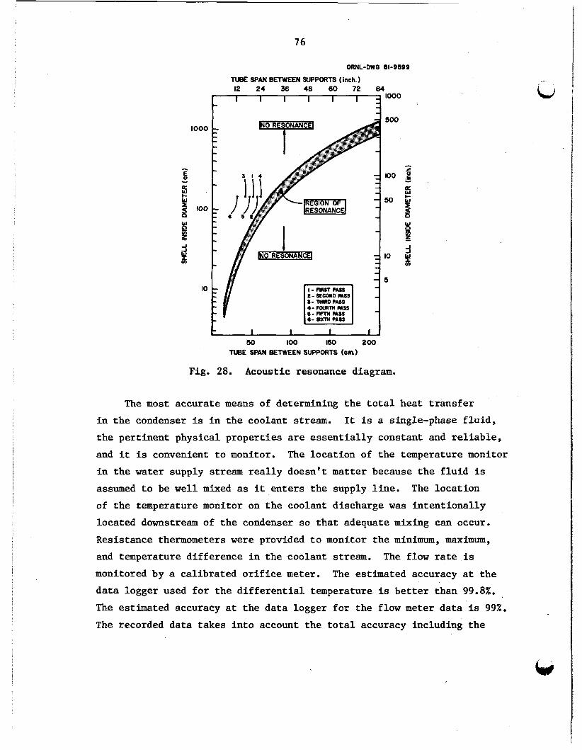
76
ORNL-DWG 61-9599
TUBE SPAN BETWEEN SUPPORTS (inch. 1
500
100
SO
IO
5
t I I I r J 50 loo 150 200
TUBE WAN BETWEEN SUPPORTS (cm)
Fig. 28, Acoustic resonance diagram.
The most accurate means of determining the total heat transfer in the condenser is in the coolant stream. It is a single-phase fluid, the pertinent physical properties are essentially constant and reliable, and it is convenient to monitor. The location of the temperature monitor in the water supply stream really doesn't matter because the fluid is assumed to be well mixed as it enters the supply line. of the temperature monitor on the coolant discharge was intentionally located downstream of the condenser so that adequate mixing can occur. Resistance thermometers were provided to monitor the minimum, maximum,
and temperature difference in the coolant stream. monitored by a calibrated orifice meter.
The location
The flow rate is The estimated accuracy at the
data logger used for the differential temperature is better than 99.8%.
The estimated accuracy at the data logger for the flow meter data is 99%.
The recorded data takes into account the total accuracy including the

77
errors encountered in the instrument, the transmission, and the recording. The accuracy of all temperature determinations is better than 99.8%. resistance thermometers (RTDs) are installed in thermowells so that they
W All
may be replaced without having to shut down the process. The vapor stream is monitored by a venturi that was installed in the
line to the existing system and is probably 98% accurate at the recorder. This isn't too helpful but can be used for making heat balances within 52%. The vapor stream pressure and temperature is monitored at three locations in the condenser: shell, and at the condensate discharge. measurement is also monitored and transmitted to the data logger. expected accuracy of the differential pressure transmitters is better than 99.8%.
99.5%.
the vapor supply line, at the midpoint in The differential pressure
The
The accuracy of the pressure at the recorder i s better than
A liquid hold up volume is provided in the funnel at the base of the condenser. in the funnel where the data are transmitted to the data logger.
A differential pressure cell monitors the liquid level
Dial thermometers with errors of less than 0.6K (l°F) have been provided at the six sample ports on the condensers whose location can be seen in Fig. 20.
with errors of no greater than 1% of the range or 14 kPa (2 psi). accurate electronic instrumentation can be added at these ports as warranted. taking the vapor samples to determine any sudden changes in the sampling conditions.
These ports are also equipped with pressure gages More
It is intended that this instrumentation be used by the person
The vapor samples are taken in 1-liter metal containers equipped with 6-nrm (0.25-in.) sample nozzles. The samples collected will be analyzed on site using a Varian chromatographic analyzer that can provide quantitative analyses on all of the pertinent hydrocarbons, oxygen, and carbon dioxide. obtain water content in the vapor and liquid isobutane samples.
The Karl Fischer method will be used to

78
10.5 Site Testing
The ORNL VFTC was fabricated at Patterson-Kelley's factory at East Stroudsburg, Pennsylvania, and shipped by truck to the geothermal test site at East Mesa, California. fabricated in Patterson-Kelley's factory at Mineral Wells, Texas.
The support frame for the condenser was
The ORNL VFTC was connected to the existing system at the 6-2
Wellhead at the test site (as was shown in Fig. 1). Testing is planned for the winter of 1981.
The test site is located in the desert region in the extreme southeastern part of California near Holtville. Imperial Valley east of El Centro.
Holtville is in the
The present schedule for testing is to run the condenser with the hpercritical Heat Exchanger Field Test (SHEFT) unit for about two weeks and then switch to the Direct Contact Heat Exchanger (DCHX) for two weeks for supply of the working fluid. is that it provides a constant source of relatively pure isobutane gas with a known composition. When the DCHX is used, about 1.5% by weight of water vapor condenser plus C02 that accumulates in the vapor stream are carried over into the condenser.
The advantages of using the SHEFT unit
The proposed scheme for evaluating the overall heat transfer coefficient of the condenser in both modes of operation is:
1. Obtain the temperature drop across the condenser, (T2 - TI) from the differential transmitter and inlet and outlet water temperatures T1 and T2.
2 .
3 .
Obtain the coolant water flow rate, Ww.
Calculate directly the overall heat transfer as shown in Eq. (31)
where C
A
= constant specific heat of water,
= total outside heat transfer area of condenser = 687 m2 (7400 ft2), P
0
Tc = condensing temperature.

79
A second calculation can be made to check the total heat transfer by accounting for the heat on the shellside. of parameters that are not immediately available such as the quality and content of steam in the vapor supply.
This involves knowledge
The scheme presented for evaluating the condenser is in reality an effort to find how good our design predictions were and to substantiate the single-tube experimental data. produced which means a vapor supply temperature of 333 K (140.6"F) at a pressure of 487 Wa (70.6 psia) and a coolant supply of 0.221 m3/s (3500 gpm) at a temperature of 300 K (80'F).
The design conditions need to be
The prime objective in testing the 5-MW condenser is to compare the field test results with results obtained in the laboratory. If these field test results are significantly different, reasonable explanations should be provided to account for the differences.
One of the proposed investigations concerns noncondeneables, mainly C02, that accumulate in the working fluid. Complete and accurate solu- bility data, equilibrium constants, and even composition of the working fluid is often lacking. Solubility data for propane and isobutane in water and water in propane and isobutane can be found in Appendix B.5 and B . 6 . The plots were obtained using Henry's Law, giving some idea of how solubility is affected by temperature at the operating pressure of the condenser.
During normal operating conditions in the DCHX mode, gas samples will be collected at each of the six sample points at various times t o
find out where and in what concentrations the noncondensables are collecting. provided, eventually equipped with a cooler condenser to strip the hydrocarbons during the venting process. CO;! will be introduced inten- tionally into the system to bring the concentration to a point where it starts to have a significant effect on the heat transfer and find out if the vents provided on the condenser can remove the noncendensable.
Once this is determined, a permanent vent or vents may be
The testing procedures will involve independently changing the flow rates of the working fluid and the coolant. rate of vapor will cause a proportional increase or decrease in the heat
Changing the mass flow
,
80
load as well as the temperature difference in the coolant. Changing the mass flow rate of the coolant should cause a proportional change in both the condensing temperature and the coolant discharge temperature and pressure, although the heat load would remain constant.
It would be desirable to observe the condensing conditions with various amounts of superheat in the vapor using a constant coolant flow rate at a constant coolant supply temperature. planned operations can be carried out will depend on the system performance,
Whether or not all the
the brine delivery conditions and the wetbulb temperature during the experimental operation period.
After completing each scheduled test with the SHEFT and DCHX units in operation, it is planned to inspect and photograph the inside of the tubes using a borescope. The 1.0-in. vent valves provide sufficient room to introduce the flexible scope into tubes beneath the valves. This procedure will give comparisons of the relative tubeside corrosion incurred in the two processes. shellside of the tubes through the vent ports to verify any fouling or oil buildups. document such problems that may be encountered.
The borescope will be used to observe the
Photographs of both the interior and exterior tubes will
Similar procedures have been used in controlled tests performed on fluted tube condensers5O in condensing ammonia for the OTEC program. Work was also done in testing a vertical-fluted-tube evaporator in conjunction with the OTEC project. 51

w 11. RELATED PRESENT AND FUTURE WORK
The turbine discharge condenser for the recently built 5-MW(e) Raft River power station in Idaho has carbon steel tubes that were designed based on the'assumption that a source of fresh coolant make-up water would be available. has 7900 19-mm (3/4-in.) diam tubes providing about 5950 m2 (64,000 ft2)
The smooth tube horizontal U-tube condenser
of heat transfer surface. The heat flux on these tubes is about 6760 W/m2 (2150 Btu/h*ft2). 695 W/m2*K (122 Btu/h*ft*'F). used as make-up for the cooling water, and replacement condensers are being considered for this unit where salt water resisting alloys must be utilized.
The expected overall coefficient is about As it turns out, geothermal brine must be
An in-depth study was made by UCC-ND for the replacement condenser. First of all, manufacturers of plate and frame, spiral, and evaporative units were contacted. All but the evaporative manufacturers declined interest for reasons of size, cost, or materials. Baltimore Air Coil could offer only stainless steel tubes and estimated the total cost to be about $1.6M (1981); they allowed for the cost of their stainless steel tubed units to be about four times the cost of the units with carbon steel tubes.
Using newly developed alloys such as SEACURE (produced by the Trent Tube Division of Colt Industries) or AL29-4C (a competitive alloy developed by Allegheny-Ludlum), it was found that a horizontal exchanger designed for this application would cost about $1.8M.
A bayonet-type exchanger requiring only 2,000 vertical fluted tubes providing 2346 m2 (25,000 ft2) of heat transfer surface could do the job with the cost estimated at less than $700 K. A more standard unit similar to the mesa condenser is estimated at $900 K. separate designs were investigated and costs estimated using the newly developed saline resistant alloys.
A total of eight
The study included two horizontal units for direct comparison - one fixed and the other U-tube. U-tube units were found to be more
81

82
expensive because the tubes had t o be sect ion welded as w e l l as bent. It is more economical t o use fixed o r f loa t ing heads i n the la rge s i z e Li u n i t s than t o employ the U-tube design.
A study has been made on compatible tubing a l loys in contact with sal t and brackish water. r e s i s t a n t t o sa l t water and aerated sal t water, which is a more severe case.
A l l of the a l loys shown i n Fig. 29 are highly
Grade AS-179 carbon steel is the only material presented ( i n
Fig. 29) t h a t i s severely attacked by salt w a t e r and is included f o r
cost comparisons.
ORNL-DWG 81-8323 RELATIVE COSTIFT
0 1.0 2.0 3.0 4.0 5.0 6.0 7.0 8.0 S.0 E I I I I I I I I
STEEL 0.57
AL. 29-4C 1.13
28 MIL W A L L TUBING
TITANIUM 1.66
304 STAINLESS STEEL 2.60
316 STAINLESS STEEL 3.75
I I
1 ~~
YONEL 400 3.85
INCONEL 600 5.10
STEEL 0.85
AL. 29-4C 1.37
90-IO CU-NI 1.39
SEACURE 1.41
I
To-so CU-NI 1.64
AL 6X 1.65 5 35 MIL W A L L TUBING
TlTINlUM 2.56
3
Fig. 29. Relative cost of s a l i n e r e s i s t a n t tube materials (March 15, 1981).
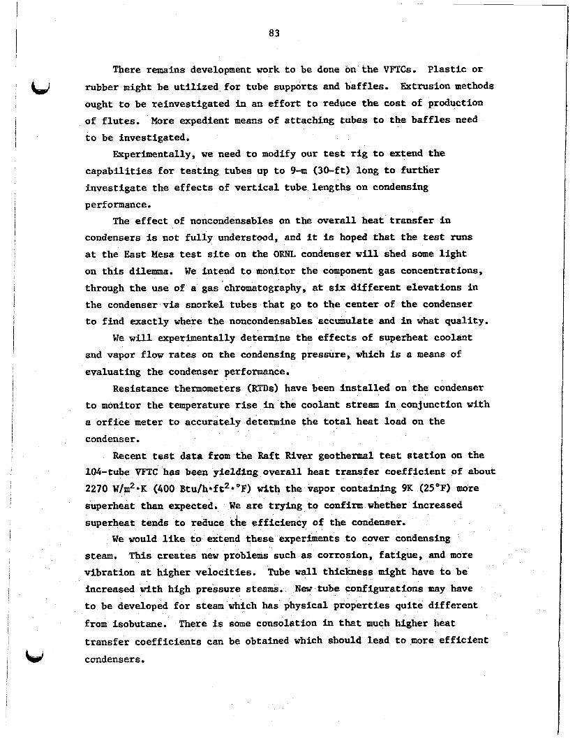
83
There remains development work t o be done on the VFTCs. P l a s t i c or
rubber might be u t i l i z e d f o r tube supports and baff les .
ought t o be reinvest igated i n an e f f o r t t o reduce the cost of production
of f lu t e s .
t o be investigated.
Ektrusion methods
Hore expedient means of attachfng tubes t o the ba f f l e s need
Experimentally, we need t o modify our test r i g t o extend t h e
capab i l i t i e s f o r t e s t ing tubes up t o 9-m (30-ft) long t o fur ther
inves t iga te the e f f e c t s of vertical tube lengths on condensing
performance.
The e f f e c t of noncundensables on the ove ra l l heat t r ans fe r i n
condensers is not f u l l y understood, and it is hoped tha t the test runs a t the E a s t Mesa test site on the ORNL condenser w i l l shed some l i g h t
on t h i s dilemma.
through t h e use of a gas chromatography, at six d i f f e ren t elevations in the condenser via snorkel tubes that go t o t h e center of the condenser
t o f ind exactly where the noncondensables accumulate and i n what qual i ty .
W e intend t o monitor the component gas concentrations,
We w i l l experimentally determine the e f f e c t s of superheat coolant
and vapor flow rates on the condensing pressure, which is a means of
evaluating the condenser performance.
Resistance thermometers (RTDs) have been in s t a l l ed on the condenser
t o monitor t he temperature rise in the coolant stream i n conjunction with
a o r f i c e meter t o accurately determine the t o t a l heat load on the
condenser.
Recent test da ta from the Raft River geothermal test s t a t i o n on the 104-tube VF'TC has been yielding overa l l heat transfer coef f ic ien t of about
2270 W/m2*K (400 Btu/h*ft2*9F) with the vapor containing 9K (25'F) more
superheat than expected.
superheat tends t o reiiuce the eff ic iency of the condenser.
I
We are t ry ing t o confirm whether increased
W e would l i k e t o extend these experiments t o cover condensing
steam.
v ibra t ion at higher ve loc i t ies .
increased with high pressure steams.
t o be developed f o r steam which has physical propert ies qu i te d i f f e ren t
from isobutane.
t r ans fe r coef f ic ien ts can be obtained which should lead t o more e f f i c i e n t
condensers.
This creates new problems such as corrosion, fa t igue, and more
Tube w a l l thickness might have t o be
New tube configurations may have
There is some consolation in that much higher heat


12. CONCLUSIONS AND RECOMMENDATIONS
&J We firmly believe that a VFTC having an overall heat transfer
coefficient of greater than 2840 w/m2*K (500 Btu/h*ft2*'F) can be built for condensing isobutane. outside fouling would have to be cut to a minimum, the exchanger operated at the optimum heat flux, max'mum tubeside velocity achieved, and probably most important, the isobotane kept free of oils and non condensables.
To accomplish this task, both inside and
A recapitulation of the good points of the VFTC includes the fact that the tube count of a horizontal-smooth-tube unit can be reduced by a factor of at least five. An added advantage is that when the number of tubes are decreased, the shell diameter is also decreased, thus saving both shell and structural material.
VFTCs can be built by standard heat exchanger manufacturers if one is willing to accept responsibility for the heat transfer performance. The manufacturers will build the unit in conformance with TEMA standards and negotiate any necessary deviations.
The major task in thfs effort was the design and procurement of the fluted tubes. inexpensive tube material, the fluting cost is, therefore, relatively high: about 75X of the total cost of the fluted tube; with expensive tube material, it can be relatively low:
The cost of the fluting is a flat "per foot" cost. With
about 20% of the total cost. The advantage of using vertical-fluted-tube exchangers is
obtaining higher overall heat transfer coefficients and condensing more vapor per unit cost than either horizontal- or vertical-smooth- tube exchangers requiring the same total tube length. are higher tubing cost, cost of sealing the tubes to the baffles, and having to resort to multipassing the coolant to achieve the desired high coolant velocities. alternatives to smooth-tube-horizontal heat exchangers for low-temperature wast heat utilization. it would make the fluted tube units even more attractive.
The disadvantages
In spite of this, fluted tubes are attractive
If some of these disadvantges could be overcome,
One means of accomplishing this objective is employing a bayonet design with the fluted tube as the sheath with a plastic tube as a
W 85

86
bayonet.
temperature increase i n the coolant i n the plastic tube.
t ha t the bayonet condenser would be t r u l y counter-current with the
condensation s p l i t evenly between the tubes.
Uisng t h i s method, there would be less than a 0.05 IC (O.l°F)
This means
P l a s t i c ba f f l e s might
be used tha t could be attached t o the tubes by appl icat ion of heat.
To f ab r i ca t e the bayonet, the f lu t ed tube would have t o be provided
with a hollow spherical t ip . These and other methods are under
current invest igat ion as are cos t comparisons on various tubing
materials su i t ab le f o r use with geothermal br ines and brackish water. As manufacturers become more familar with f lu ted tubes and f lu t ed tube
exchangers, the fabr ica t ion cos ts w i l l be reduced and we should see
more of these un i t s i n i n d u s t r i a l usage.
ACKNOWLEDGMENTS
This report was done ib cooperation with the Energy Division through J. W. Michel as part of the Waste Heat Rejection Program sponsored by the U.S. Department of Energy, Division of Geothermal Energy, under Contract No. W-7405-end-26 with Union Carbide Corporation' s Nuclear Division (UCC-ND) .
I wish to acknowledge the help of several members of the UCC-ND staff who made contributions to this report as well as to the design and development of the East Mesa condenser:
Dr. E=. H. Luk of the Systems Engineering Department performed the vibrational analysis and verified the arrangement of the baffles and tube supports.
W. D. Hoyle did the drafting work and contributed many original ideas to the conceptual design of the condenser. D. J. Kincaid did the excellent graphics contained in the report.
J. W. Wells and W. P. Huxtable, although not assigned to the
T. Whitus and
project, are thanked for their consultation on condensation theory and excellent references.
I also wish to express my appreciation to J. W. Michel of the Energy Division and the Project Manager, who orginally suggested the project, and to Drs. R. W. Murphy and M. Siman-Tov, who reviewed the report and offered technical consultation.
87


LJ 1.
2.
3.
4.
5.
6.
7.
8.
9.
10.
REFERENCES
K. J. Bell, Condensation, 8th International Heat Transfer Conference, Paris, France, August 1978, Vol. 111, pp. 361-375.
Vehara Hervo, Design of Condensers, Thermal Pollution Administra- tion (Netsu Kanri to Kogai), g(9-12).
Jerry Taborek, Heat Exchanger Design, 6th International Heat Transfer Conference, Paris, France, August 1978, Vol. 111, pp. 269-283.
Jerry Taborek, "Evolution of Heat Exchanger Design Techniques, Heat Transfer .&&neering, l(1): 15-29 (July-September 1979).
R. Gregorig, "Hautkondensation an feingewelten oberflachen bei Berksichtigung der Oberf lachen spannungen," 2. angm. Math. Phys. , - V, 36-49 (1954). R. L. Webb, "A Generalized Procedure for the Design and Optimiza- tion of Gregoric Condensing Surfaces," J. Heat Transfer, 101, 335-339 (May 1979).
T. C. Carnavos, "Augmenting Heat Transfer in Desalination Equipment with Fluted Surfaces," Office of Saline Water Symposium on Enhanced Tubes for Distillation Plants, Washington, D.C. (March 1969).
L. G. Alexander and H. W, Hoffman, Improved Heat Trarpfer Systems for Evaporators -Perforname Chaxaeteristics of Advanced Evaporator Tubes for Long Tube VerticaZ Evaporators, ORNLITM-2951 (January 1971).
D. G. Thomas, "Enhancement of Film Condensation Heat Transfer Rates on Vertical Tubes by Vertical Wires," Am. Int. Chem. Eng. J., -9 14 644 (1968).
D. G. Thomas, "Enhancement of Film Condensation Rate on Vertical Tubes by Longitudinal Fins," Am. Int . Chem. E"ng. J . , 14(4): 644-649
(July 1968).
i
i w 1 I I I 89
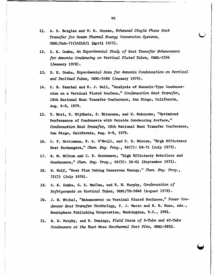
90
11.
3.2 .
13.
14.
l.5.
16 .
17.
18.
19.
20.
21.
A. E. Bergles and M. K. Jensen, EnhmK?ed S & g h Phase H e a t -fer for Ocean TbrrnaZ lhergy Conversion Systems, ORwL/Sub-77/1421611 (April 1977) . s. K. combs, An E3cperimentat Study of H e a t Transfer m-emmt for Ammonia Condensing on VertiCaZ nuted !kba, OWL-5356
(January 1978).
S. K. Combs, EccperhentaZ k t a for A??unm&x ConderPsath m Verticat und IneZSned Ti.&s, ORNL-5488 (January 1979).
C. B. Panchal and K. J. B e l l , "Analysis of Nussslt-Type Condensa-
t i o n on a V e r t i c a l Fluted Surface," C o d m s a t h Heat W w f e r , 18th National 3eat Transfer Conference, San Diego, California,
Aug. 6-8, 1979.
P. Mori, K. Ujikata, S. Birasawa, and W. Nakayama, "Optimized
Performance of Condensers with Outside Condensing Surface,"
C o n d e n s a ~ Heat zlrumsfer, 18th National Heat Transfer Conference,
San Diego, California, Aug. 6-8, 1979.
C. F. Gottzmann, P. S. O ' N e i l l , and P. E. Minton, "High Efficiency
Heat Exchangers," them. Eng. Prog., 69(7) : 6 9 7 5 (July 1973) . R. PI. Milton and C, F. Gottzmann, "High Efficiency Reboilers and
Condensers," Chem. Erg. Prog., 68(9) : 56-61 (September 1972) . W. Wolf, "Hea t Flu Tubing Conserves Energy," chem. Ehg. Prog., 72(7) (July 1976).
S. R. Combs, G. S. Mailen, and R. W. Murphy, Codensatwn of Ref&germrts on Verticcxz Tu.be6, ORNL/TM-5848 (August 1978).
J. W. =&el, "Enhancement on Vertical Fluted Surfaces," Power Con- denser Beat Transfer !TechvioZogy, P, J. Marto and R. H. Nunn, eds. s
Hemisphere Publishing Corporation, Washington, D.C., 1981.
R. W. Murphy, and N. Domingo, FSeZd Tests of %Tube (XVLd 4U-lkrbe Condensers a t the East Mesa &othermat Test Site, ORNL-5852.
-

22.
23.
24.
25.
26.
27.
28.
29.
30.
31.
32.
33 .
91
No A. Samurain and J. R. Shields, "Preliminary Design of Axial Flow Hydrocarbon Turbine , " Generatar Set for GeothermaZ AppZZca- t w n s , EPRI ER 513 (May 1979).
K. E. Starlings, n u i d Thermodydc Properties for Light Hydro- carbon Systems, Gulf Publishing Company, Houston, Texas, 1973.
D. H. Riemer, H. R. Jacobs, R. F. Boehm, and D. S. Cook, "A Computer Program for Determining the Thermodynamic Properties of Light Hydrocarbons," UTEC ME 76-211.
American Petroleum Institute, TeohnioaZ Data Book, PetroZuem Refining, 2d ed., 1970.
W. M. Rohsenow and J. P. Hartnett, Handbook of Heat Transfer, pp. 7-32, McGraw Hill, New York, 1973.
J. H. Perry, ChdoaZ Engineers Handbook, 4th ed., pp. 10-14, McGraw Hill, New York.
David Butterworth and L. B, Cousins, "Use of Computer Programs in Heat Exchanger Design," Chem. Eng. (NiY.), 83(14): pp. 72-76 (July 5, 1976).
D. F. Other, Ph.D. Thesis, University of Michigan (19271, Ind. Eng. Chem. 2 l , 576 (1929).
F. C. Standiford, W e L. Badger Associates, Inc., Greenbank, Washing- ton, "Effect of Noncondensibles on Condenser Design and Heat Trans- fer, Chem. Gng. Pqvg., 75(7): 59 (July 1979).
A. P. Colburn and 0. A. Houghton, "Design of Condensers for Mixtures of Vapors with Noncondenslng Gases," Ind. Eng. Chem., 26(11): 1170-82 (November 1934).
R. G. E. Franks, Modezing and Simuhtion i n ChemioaZ Engineering, Wiley-Interscience, New York, 1972,
J. Prausnitz, T. Anderson, E. Gren6, C, Eckert, R, Hsieh, and J. 0' Connell, Computer CalaulutionB far httfoomponent Vapor-L.tquid and L$quid-Liqu&i? EquiZibAa, Prentice-Hall International Series In
the Physical and Chemical Engineering Sciences, Prantice Hall, Inc., Englewood Cliffs, New Jersey, 1980.

92
34 . 35.
36.
37.
38 .
39.
40.
41.
42.
43.
44.
45.
46.
47.
N. Domingo, Condensation of RefAgerant-11 on the Outside of VerticaZ E n h e d Tubes, ORNL/TEf-7797 (August 1981).
C. E. Gilmore, "No Fooling, No Fouling," chem. Eng. Bog. , 61(7): 49-54 (July 1965)
Standurds of TubuZar Eccchmrger Manufacturers Assocktion, 6th ed., New York, 1978.
D. Q. Kern, Process Heat Transfer, p. 845, McGraw Hill Book Company, New York, 1950.
C. J. Dobratz and C. F. Oldershow, "Desuperheating Vapors in Con-
densers Unnecessary," G u m . Eng. (N.Y. ), 74, 146 (July 31, 1967).
S. W. Churchill, "Friction-factor Equation Spans all Fluid-Flow Regimes," Chem. Ehg. ( N . Y . ) , 84(24), 9$-92 (Ndvember 3, 1977).
D. Q. Kern, Process Heat l'ransfer, p. 273, McGraw-Hill Book Company, New York, 1950.
K. J. Bell, "Final Report of the Cooperative Research Program on Shell and Tube Heat Exchangers," Bulletin #5, University of Delaware , Newark, Delaware (June 1953) . J. W. Palen and Jerry Taborek, "Solution of Shell Side Flow Pressure Drop and Heat Transfer by Stream Analysis Method," Chem. Eng. €909. Symp. Ser., Heat Transfer - Philadelphia 92(65): 53-63.
J. H. Perry, ChemicaZ Engineering Handbook, 4th ed., pp. 5-30,
Eq. (5-91), McGraw-Bill Book Company, New York.
D. A. Donahue Heat Transfer and Pressure Drop in Heat Exchangers, Ind. Bag. Chem., 41: 2499 (1943).
D. F. Rudd and C. C. Watson, S t m t s g y ofProces8 Engineering, pp. 40-50, John Wiley 61 Sons, New York, 1968.
S. Timoshenko and D. H. Young, Vibration Probzems i n Ehghering, p. 338, 3d ed., D. Van Nostrand Company, 1966.
K. H. Lub, ORNL Engineering Division, private communication, June 1979.

48.
49.
50.
51.
93
P. M. Morse, Vibration and Sound, 2d ed., McGraw-Hill, 1948.
J. F. Whitbeck, "Measurement and Control Techniques in Geothermal Power Plants ,'I TREE-1312 (January 1979) . L. G. Lewis and N. F. Sather, O!l'EC Perfomname Tests of ths Camegie-Me ZZon University VerticaZ Fluted !Tube Condenser, ANL/OTEC-PS-S (May 1979)
James Lorentz, D. T. Yung, D. L. Hillis, and N. F. Sather, M%C
Perforname Te8t8 of the Carnegie-Mellon University Vertwal Fluted !Tube Evaporator, ANL/OTEC-PS-5 (July 1979) .

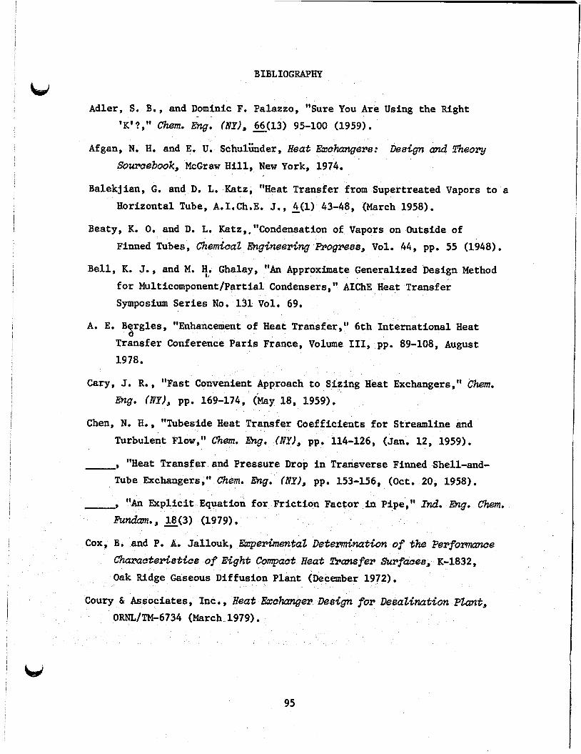
BIBLIOGRAPHY
bd Adler, S. B., and Dominic F. Palazzo, "Sure You Are Using the Right
'K'?," Chem. &gi (NY), - 66(13) 95-100 (1959) . Afgan, N. H. and E. U. Schulkder, Heat Exchangers: Descgn Lznd Theory
Somcebook, McGraw Hill, New York, 1974.
Balekjian, G. and De Le Katz, "Heat Transfer from Supertreated Vapors to a Horizontal Tube, A.1.Ch.E. J,, k(l) 43-48, (March 1958).
Beaty, K. 0, and De L. Katz,,"Condensation of Vapors on Outside of Finned Tubes, C h e ~ c a z lhginesring A.ogre88, Vol. 44, pp. 55 (1948).
Bell, K. J., and M. He Ghalay, "An Approximate Generalized Design Method s, for Multicomponent/Partial Condensers," ALChE Heat Transfer Symposium Series No. 131 Vol. 69,
A. E. B rgles, "Enhancement of Heat Transfer," 6th International Heat Transfer Conference Paris France, Volume 111, pp. 89-108, August 1978 .
8
Cary, J. R., "Fast Convenient Approach to Sizing Heat Exchangers," Chem. Gng. (NY), pp. 169-174, ( b y 18, 1959) .
Chen, N. He, "Tubeside Heat Transfer Coefficients for Streamline and Turbulent Flow," &em. Eng. (IVY), pp. 114-126, (Jan. 12, 1959).
-' "Heat Transfer and Pressure Drop in Transverse Finned Shell-and- Tube Exchangers," Chem. fig. (fly), pp. 153-156, (Oct. 20, 1958).
-' "An Explicit Equation for Friction Factor in Pipe," I&. Ehg. Chem. Fundam., g(3) (1979).
Cox, B. and P. A. Jallouk, ExpemhentaZ Detenrdnation of the P e r f o m m e Chmactsr*i8tics of Eight Compact Heat !l!ransfer Surfaoe8, K-1832, Oak Ridge Gaseous Diffusion Plant (December 1972),
Coury & Associates, Inc., Ilea$ Exchanger Design for DesaZ&ation PZant, ORNLIW6734 (March 1979) .
95

8 96
Diehl, J. K. and C. H. Unruh, "Two Phase Pressure Drop for Horizontal Crossflow through Tube Banks," Pet. Refiner, =(lo) 124-120 (October 1958).
D. M. Eissenberg et al, Enhanced Tubes for Seawater D i s t i t k t i o n P h t s , ORNL-TM-2611 (August 1969).
Edwards, D. K., K. D. Gier, P. S. Ayyaswamy, and I. Cotton, "Evaporation and Condensation in Circumferential Grooves on Horizontal Tubes, ASME Publication, 73-HT-251 (1973).
Ellis, P. F., I1 and M. F. Conover, Mate&ala Selection GuideZ<nes for Geotheml Energy U t i l i z a t h Systems, DOE/RA/27026-1 (January 1981).
Fanaritis, J. P. and J. W. Bevevino, "Designing Shell and Tube Heat Exchangers," Chem. Eng. (NY), 62-71 (July 7, 1976).
Foxhall, D. H. and P. T. Gilhert, "Selecting Tubes for CPI Heat Exchangers," Chem. Eng. (NY), pp. 148-150, (April 12, 1976); 11, pp. 101-104 (April 26, 1976); 111, pp. 133-fi5 (May 10, 1976).
Fujii, T. and H. Honda, "Laminar Filmwise Condensation on a Vertical Sing-= * ' Fluted Plate," Proceedings of 6th InternutiomZ Heat Transfer
Conference, Vol. 2, pp. 419-424 (1978).
Fujii, T. et al., "Heat Transfer and Flow Resistance in Condensation of Low Pressure Steam Flowing Through Tube Banks ,It International Journal of Heat and Mass Transfer Vol. 15 347-359, Pergamon Press, London, England.
Gallant, R. W., "SizingtSipe for Liquids and Vapors," Chem. Eng. (NY), pp. 96-104, (Feb. 24, 1969).
Ganapathy, V., "Quick Calculation for ExChanger Tubedeet; Thicl~nes8,~~ Chwn. Eng. (NY), p. 114, May 12, 1975.
Gloyer , Walter, Thermal Desi@ of Mhed Vapor Condenser8, Hydrooarbon Process., Part 1: pp. 103-107, (June 1970); Part 2: pp. 107-110 (July 1970).
Green, M. A. and H. S. Pines, CalcuZath of GeothermaZ Power Plant Cycles Using Program GEOTHM, LBL-3238, (October 1975).
i
i
97
Gutteman, G., "Specify the Right Heat Exchanger," Hydrocarbon PTocess., pp. 161-163, (April 1980) .
Halford, J. A., ORICON: A Fortran Code for the CalcuZation of A Steam Condenser o f C h d a r &os8 Section, ORNL-Tb-4248, (July 1973).
Heat Exchange Institute Standm?ds for Steam Surface Condensers, Seventh
Ed it ion . Heidemann, R. A., "Three-Phase Equi l ibr ia Using Equations of State,"
AIChE J. 20 (5) 847-855 (September 1974).
Hirasawa, S., K. Hijikata, Y. Mori, and W. Nakayama, "Effect of Surface
Tension on Laminar Film Condensation along a Vertical P l a t e with a Small Leading Radius, Proceedings of S k t h IntemtionaZ Heat Transfer Conference, Vol. 2, pp. 413-418 (1978).
-' "Effect of Surface Tension on Laminar Film Condensation (Study
of Condensate Film i n a Small Groove)," 2'!ran8actions of JSME, Vol. 44, pp. 2041-2048 (1978).
Holt, Co., Ben, GeothermaZ Heat Exchanger Test a t Heber, CaZ<forn<a, EPRI ER-572 (August 1978).
Johnson, R. W., H. R. Jacobs, and R. F. Boehm, Direct Contact Heat Transfer Between Two ImmCscibZe L;quids i n Lmrhar FZm Between PamZZeZ PZates, DGE/1549-1 (December 1975).
3
Kestin, Joseph, AvaiZabZe Work i n Geothermal Energy, COO-4051-25,
USDOE Geothermal Energy (July 1978).
-9 Source Book on the Production of EZectricity from GeothermaZ Energy, DOE/RA/28320-2, U.S. Department of Energy (March 1980).
Khalifa, H. E. and Michaelides, m e Effect of NoncmrdensibZe Gases on the Perfommace of GeothermaZ Steam Power Systems, COO-4051-36
(November 1978) . \
Krishna, Rajamani and C. B. Panchal, "Condensation of a Binary Vapor
Mixture i n the Presence of an I n e r t Gas,'' ChdcaZ Engineering 45, Pergammon Press, Great Bri ta in , 1977.

98
Krishna, R. et al., "An Ackerman-Colburn and Drew Type Analysis for Condensation of Multicomponent Mixtures , I 1 Letters in Heat and Mass !Transfer, - 3, 163-172 (1976).
Kruger, Paul and Care1 Otte, GeothemaZ Energy ResOW)Ce8, Production, and ShZatwn,Stanford University Press, Stanford, Calif., 1973.
Lahaye, P. G., F. J. Neugebauer, R. K. Sakhuja, A Generalized Prediction of Heat Transfer Surfaces, J. Heat !Z'ransfer, pp. 511-517 (November 1974).
Leach, M. J., "An Approach to Multiphase Vapor-liquid Equilibria," Chem. hg. ( f ly) , pp. 137-140, (May 23, 1977).
Levi, J. E., "New Developments in Basics of Cooling Water Treatment," Chem. Eng. (NY), pp. 88-92, (June 10, 1974).
Lord, R. C., P. E. Minton, and R. P. Slusser, "Guide to Trouble Free Heat Exchangers," Chem. Eng. (IVY), pp. 153-160 (June 1, 1970).
Matheson Company, Matheson Cas Data Book, Matheson Co. Inc., East Rutherford, N.J.
Michel, J. W., and R. W. Murphy, "Enhanced Condensation Heat Transfer," Heat Transfer - Orlando AIChE Symposium Series pp. 183-191, (1980).
Milora, S. L. and S. K. Combs, Thermodynamic Representatwns of Anrmonia and. Isobutane, ORNL/TM-5847 (May 1977).
Milora, S. L. and J. W. Testor, Geothermat Energy as A Source of EZectric Power, MIT Press, Cambridge, Mass., and London, England, 1976.
Mothershed, C. T., ORMZF: A FORTMN Code for Computing Detail Muzti-effect MuZtistage FZash Evaporization DesaZimtion Plant Designs, ORNL/TM-1560 (August 1966).
MPR Associates, Assessment of Condenser Leakage ProbZems, EPRI-NP-1467 (August 1980).
Mueler, Alfred C., "An Inquiry of Selected Topics on Heat Exchanger Design," Donald Q. Kern Award Lecture, 1975, Sixteenth National Heat Transfer Conference, St. Louis, Mo., (August 9, 1976).

99
Nakayama, W., T. Daikoku, H. Kuwahara, and K. Kakizaki, "High-Flux Heat Transfer Surface 'THERMOEXCELL' , I1 Hitachs Revia , 24 (8), pp. 329-334 (1975).
Neill, D. T., GeothermuZ SheZZ and !&be Heat fiohmrger Augmenhth, TREE-1023, (November 1976).
Neitzel, J. W., Cooling Methods Study for the Proposed Raft River GeothemZ Power Plant, ANCR-1203 (April 1975) .
Newson, I. H. and T. D. Hodgson, "The Development of Enhanced Heat Transfer Condenser Tubing," DesaZimtwn, Vol. 14, pp. 291, (1978).
ORNL Engineering, Design Guide for Heat Transfer Eqdpen t in Water Cooled NucZsar Reactor Systems, ORNL/TM-3573 (July 1975) .
Ramalho, R, S. and F. M. Tiller, "Improved Design Methods for Multipass Exchangers" Chem. Ens. NY, pp. 87-92, (March 29, 1965).
Robertson, R. C., Waste Heat R j e c t w n from CeothermaZ Potter Stations, ORNL/TM-6533 (December 1978).
Row, M. et al., "Heat Transfer and Air Blanketing in Steam Condensers," I Mech E, pp. 153-162 (1979).
Schrodt, J. Thomas, "Simultaneous Heat and Mass Transfer from Multi- component Condensing Vapor-Gas Systems," AIchE J., l9(4), pp. 753-759 (July 1973).
Short, B. E., "Heat Transfer and Pressure Drop in Heat Exchanges," Engineering Research Series No. 37, Bureau of Engineering Research, University of Texas Publication No. 4324 (June 22, 1943).
Spencer, R. A., Jr., "Predicting Heat-Exchanger Performance by Successive Summation, " Eng., pp. 121-126, (Dec. 4, 1978).
Starczewski, J., "Short-Cut Method to Exchanger Tube Side Pressure Drop," Hydrocarbon Boo. pp. 121-124 (May 1971).
Starling, K. E. and L. W. Fish, ESN, A M-ixture rszerpnOdynamic Computer Progrmn, ORO-4944-2 (December 1975)

100
Stephan, K., "Application of Multicomponent Thermodynamics t o the
Calculation of Thermal Separation Processes," Ger. &em. hzg., pp. 269-278 (1980)
Stern, Frederick and Votta Ferdinand, "Condensation from Superhead
Gas-Vapor Mixtures," AIChE J. - 14(6) (November 1968).
Taborek, J., "Evolution of Heat Exchanger Design," Heat llrcrnsfer Engineer- ing, - 1, 15-28 (July-Sept. 1979).
Tallackson, J. R., CACHE-An Extended BASIC Program Which Computes the Perfommace of Shell cznd Tube Heat Exchangers, ORNL/TM-4952
(March 1976).
Taneyama, T. and S. Simizu, "On t he Transition of Dropwise-Film Conden-
sation," Proc. of 5th Intematwnal Heat Transfer Conference, Vol. 3, pp. 274 (1974).
T l e i m a t , B. W. e t al., Hydrocarbon Heat !&ansfer Coefficients PreZMnary Isobutane Results, LBL-8645 (February 1979).
Turner, S. E. and W. W. Madsen, HEDCOR, A Heat Exchanger and Design Optimization Routine, TREE-1112 (April 1977).
Uehara, H., K. Masutani, and M. Miyoshi, "Heat Transfer of Condensation
on Vertical Fluted Tubes," pp. 146-160 i n Proceedings of the 5th
Ocean Them2 hergy Conversh Confemnce, M i a m i Beach, Fla.,
Feb. 20-22, 1978. DOE Report CONF-780236, Vol. 3, Sec 6.
Wahl, E. F. and F. B. Boucher, Theory and Practice of Near Criticaz Pressure Direct Contact Heat Exchrmge, SNA/1076-1 (October 1977).
Webb, R. L.; and M. J. Scott , "A Parametric Analysis of t he Performance
of Internal ly Finned Tubes f o r Heat Exchanger Application," !hznss-
actions of the ASME JownaZ of Heat Transfer, 102, 38-42 (February
1980).
Wenzel, H. and W. Rupp, "Calculation of Phase Equi l ibr ia i n Systems
Containing Water and Supercr i t ical Components," ChenrLcaZ hzgineering Science, -9 33 683-687 (1978).

101
i
Williams, A. G., S. S. Nandapurkar, and F. A. Holland, "A Review of Methods for Enhancing Heat Transfer Rates in Surface Condensers, fie Chdcai? Engineer, No. 233, pp. CE 367-373 (1968).
Wilson, J. L., "The Design of Condensers by Digital Computers," Paper presented at the Symposium on Design Decision and the Computer, Institution of Chemical Engineers, England (1972).
Yamamoto, Hiroshi and Toyoaki Ishibachi, "Calculation of Condensation Heat Transfer Coefficients of Fluted Tubes. gravitation and valley flow," Heat Transfer -Jp. Res., - 7(3) 49-54 (Eng.) (1978)
The effects of

,

Appendix A
CONVERSIONS (METRIC/ENGLISH, ENGLISH/METRIC)
All quantities used in this report have been expressed in Scientific International (SI) units with the corresponding American Common Usage (ACU) units. ACU units to the corresponding SI units. to convert from SI units into the corresponding ACU units.
Table A,1 gives the factors to convert from Table A.2 gives the factors
Table A.1. Factors to convert from American Common Usage (ACU) units into Scientific
International (SI units)
To convert from To Multiply by
Btu/h Btu/h* f t2 Btu/h*ft*OF Btu/h* f t2 OF Btu/lb, Btu/lb,* OF ft lb/h f t2
f t/h2 fPS gpm in . Ib/h lbf/f t II+J f t 3
lbm/h-f t lb/h* f t2 psia
A(*F)
0.2929 2.152 1.730 5 . 675 2.324 x lo3 4.184 x lo3 0 . 3048 1.263 x
0.0929 2.35 x 0 3048
6,309 x 2.54 1.263 x lo4 14 . 59 16.02 4.134 x 1.356 x loo3 6.895 x l o 3
A(K) or ("C) 0.5556
Temperature conversion: T(K) = 5/9 [T(OF) - 321 + 273.15
103
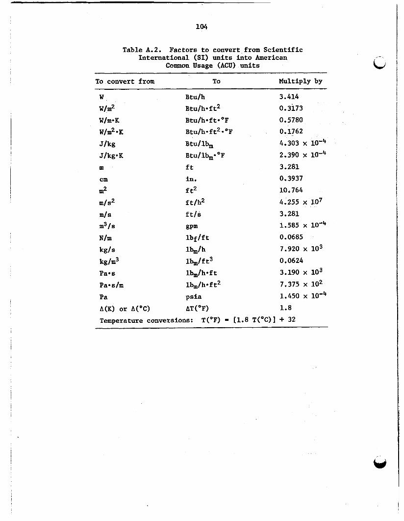
104
Table A.2. Factors to convert from Scientific International (SI) units into American
Common Usage (ACU) units
To convert from To Multiply by
Btu/h Btu/h* f t2 Btu/h* f t* O F Btu/h*ft2*OF Btu/lb, Btu/lbm* OF ft in . ft2 ft/h2 f t/s
gPm lbf/f t
lb&
3.414 0.31173 0.5780 0.1762 4.303 X
2.390 x
3 , 281 0.3937 10.764 4,255 x lo7 3.281 1.585 x loe4 0 . 0685 7.920 x lo3
kg/m3 1k/ft3 0 , 0624 Pa*s l&/h*ft 3.190 x lo3
Pa*s/m lb/h*f t2 7.375 x 10² Pa psia 1.450 x
A(K) or A("C) AT('F) 1.8
Temperature conversions: T(OF) = j1.8 T(OC)] 4- 32

br Appendix B
PROPERTIES OF ISOBUTANE
Appendix B contains data on pertinent thermodynamic and physical
propercteis of isobutane.
as a function of temperature at a pressure of 1 a t m .
the vapor pressure of isobutane as a function of temperature.
shows the spec i f ic heat of isabutane gas a t 1 a t m as
temperature.
as a function of temperature and pressure.
of both propane and isobutane i n water as functions of temperature.
Figure B.6 shows the so lub i l i t y of water in propane and isobutane as
functions of temperature.
presented i n Ref. 25.
Figure B.l shows the l a t e n t heat of isobutane
Figure B.2 shows
Figure B.3
Figure B.4 is a diagram showing the enthalpy of isobutane Figure B.5 shows the so lub i l i t y
These data have been abstracted from equations
a t a Fig. B.1. pressure of 1 a t m .
Latent heat of i s c ibutane as a function of’temperature
105

I 106
Fig. B.2. Vapor pressure of isobutane as a function of temperature.
1850 v)
i3
CWL-DWG e i - m m
1 0.45
TEMPERATURE, OF 50 60 fo 80 90 1 0 0 110 120 130 l40 150
t I I I I I I I I I
1 I I I I I
290 300 310 320 330 TEMPERATURE, K
Fig. B.3. Specific heat of isobutane gas at 1 am.

bi
107
Fig. B.4. Enthalpy of isobutane as a function of temperature and pressure.
Fig. B.5. Solubility of propane and isobutane in water as functions of temperature,

E t f
b
i jg s:
L /
Fig. B . 6 . Solubility of water i n propane and isobutane as functions of temperature.

Appendix C
PROPERTIES OF WATER
Table C.l shows the physical properties of water over the appropriate temperature range of the cooling water. The properties include the density, dynamic viscosity, thermal conductivity and Prandtl Number. The specific heat of water is assumed to be constant over the temperature range considered.
Table C.1. Propertles of saturated watera ~~ ~ ~~
T P F! k lb/ft*h W/m K Btu/h*ft°F NPr k OF tg/m3 lb/ft3 Pas
273 32 277 40 283 50 289 60 294 70 300 80 305 90 311 100 316 110 322 120 327 130 333 140 339 150
1000 1000 999 999 998 996 995 993 991 989 986 983 980
62.42 62.42 62.38 62.34 62.27 62.17 62.11 61.99 61.84 61.73 61.54 61.39 61.20
0.00179 0.00155 0.00130 0.00112 0.00098 0.00086 0.00076 0.00068 0.00062 0.00056 0.00051 0.00047 0.00043
4.33 3.75 3.17 2.71 2.37 2.08 1.85 1.65 1.49 1.36 1.24 1.14 1.04
0.566 0.574 0.585 0.595 0.604 0.614 0.623 0.630 0.637 0.644 0.649 0.654 0.659
0.327 0.332 0.338 0.344 0.349 0.355 0.360 0.364 0.368 0.372 0.375 0.378 0.381
13.37 11.36 9.41 7.88 6.78 5.85 5.13 4.52 4.04 3.65 3.30 3.01 2.72
T = temperature, Cp = specific heat = 1.0 Btu/lb.OF or cal/gm*K, = dynamic viscosity, k = thermal conductivity, and
a p = density, Npr I= Prandtl Number (dimensionless).
109 i


Appendix D
SHELLSIDE PRESSURE DISTRIBUTION
Appendix D shows the pressure distribution in the East Mesa condenser. The vapor velocity, the amount of condensate obtained on each row, the total condensate obtained, and the incurred pressure drop are tabulated for each row of each shell pass. D.6 show the data for the first pass through the sixth pass and indicate the baffle spacing for each pass. passes: baffles, 6; total tube length, 6, 6168 m (20,239 ft); temperature, 307.57 K (94.0'F); pressure, 493.68 kPa (71.60 psi); gas flow rate, 12.55 kg/s (99,400 lb/h); entrance loss to be added to total pressure drop, 715.22 Pa (0.1037 psi).
Tables D.l through
The following is the same for all
111

Table D.l. Pressure distribution through the first shell pass of the East Mesa condenser with a baffle spacing of 1.52 m (60 in.)
Vapor velocity Condensed/row Total condensed Pressure drop Row Number number of tubes (m/s) (ft/s) (liters/s) (gal/min) (liters/s) (gal/min) kPa Psi
1 30 2 31 3 32 4 34 5 35 6 36 7 37 8 38 9 40 10 40 11 40 12 41 13 41 14 41 15 41 16 41 17 41 18 41 19 41 20 41 21 40 22 40 23 40 24 38 25 37 26 37 27 36 28 34 29 34 30 33 31 31 32 30
3.269 3.142 3.021 2.823 2.719 2.620 2.526 2.435 2.291 2.265 2.239 2.160 2.134 2.108 2.082 2.056 2.030 2.004 1.978 1.952 1.973 1.947 1.921 1.993 2.019 1.993 2.020 2.109 2.083 2.118 2.224 2.269
10.73 10.31 9.91 9.26 8.92 8.60 8.29 7.99 7.52 7.43 7.35 7.09 7.00 6.92 6.83 6.74 6.66 6.57 6.49 6.40 6.47 6.39 6.30 6.54 6.62 6.54 6.63 6.92 6.83 6.95 7.30 7.45
0.188 0.194 0.200 0.213 0.219 0.225 0.231 0.238 0.250 0.250 0.250 0.256 0.256 0.256 0.256 0.256 0.256 0.256 0.256 0.256 0.250 0.250 0.250 0.238 0.231 0.231 0.225 0.213 0.213 0.206 0.194 0.188
2.973 3.072 3.171 3.369 3.468 3.568 3.667 3.766 3.964 3.964 3.964 4.063 4.063 4.063 4.063 4.063 4.063 4.063 4.063 4.063 3.964 3.964 3.964 3.766 3.667 3.667 3.568 3.369 3.369 3.270 3.072 2.973
0.188 0.381 0.581 0.794 1.013 1.238 1.469 1.707 1.957 2.207 2.457 2.713 2.970 3.226 3.482 3.739 3.995 4.251 4.508 4.764 5.014. 5.264 5.514 5.752 5.983 6.215 6.440 6.652 6.865 7.071 7.265 7.453
2.97 6.05 9.22 12.59 16.05 19.62 23.29 27.05 31.02 34.98 38.95 43.01 47.07 51.13 55.20 59.26 63.32 67.39 71.45 75.51 79.48 83.44 87.40 91.17 94.84 98.50 102.07 105.44 108.81 112.08 115.15 118.13
0.020 0.039 0.056 0.071 0.085 0,099 0.111 0.123 0.134 0.144 0.154 0.164 0.173 0.182 0.191 0.199 0.208 0.216 0.224 0.232 0.240 0.248 0.256 0.264 0.272 0.280 0,289 0.298 0.307 0.316 0.326 0.336
0.003 0.006 0.008 0.010 0.012 0.014 0.016 0.018 0.019 0.021 0.022 0.024 0.025 0.026 0.028 0.029 0.030 0.031 0.033 0.034 0.035 0.036 0.037 0.038 0.039 0.041 0.042 0.043 0.044 0.046 0.047 0.049

c c
Table D.2. Pressure distribution through the second shell pass of the East Mesa condenser with a baffle spacing of 1.11 m (44 in.)
Vapor velocity Condensed/row Total condensed Pressure drop Row Number number of tubes
(m/s) (ft/s) (liters/s) (gal/min) (liters/s) (galjmin) kPa Psi
1 2 3 4 5 6 7 8 9 10 11 12 13 14 15 16 17 18 19 20 21 22 23 24 25 26 27 28 29 30 31 32
30 3.064 31 2.943 32 2.828 34 2.642 35 2.543 36 2.448 37 2.358 38 2.272 40 2.136 40 2.110 40 2.084 41 2.009 41 1.982 41 1.956 41 1.930 41 1.904 41 1.878 41 1.852 41 1.826 41 1.800 40 1.818 40 1.792 40 1.766 38 1.830 37 1.851 37 1,825 36 1.848 34 1.927 34 1.902 33 1.931 31 2.025 30 2.064
10.05 9.66 9.28 8.67 8.34 8.03 7.74 7.45 7.01 6.92 6.84 6.59 6.50 6.42 6.33 6.25 6.16 6.08 5.99 5.91 5.96 5.88 5.79 6.00 6.07 5.99 6.06 6.32 6.24 6.34 6.64 6.77
0.138 0.142 0.147 0.156 0.160 0.165 0.170 0.174 0.183 0.183 0.183 0.188 0.188 0.188 0.188 0.188 0.188 0.188 0.188 0.188 0.183 0.183 0.183 0.174 0.170 0.170 0.165 0.156 0.156 0.151 0.142 0.138
2.180 2.253 2.326 2.471 2.544 2.616 2.689 2.762 2.907 2.907 2.907 2.980 2.980 2.980 2.980 2.980 2.980 2.980 2,980 2.980 2.907 2.907 2.907 2.762 2.689 2.689 2.616 2.471 2.471 2.398 2.253 2.180
7.590 7.732 7.879 8.035 8.195 8.360 8.530 8.704 8.888 9.071 9.254 9.442 9.630 9.818 10.006 10.194 10.382 10.570 10.758 10.946 11.130 11.313 11.496 11.671 11.840 12.010 12.175 12.331 12.487 12.638 12.780 12.918
120.31 122.56 124.88 127.35 129.90 132.51 135.20 137.96 140.87 143.78 146.69 149.67 152.64 155.62 158.60 161.58 164.56 167.54 170.52 173.50 176.41 179.32 182.22 184.98 187.67 190.36 192.98 195.45 197.92 200.32 202.57 204.75
' 1.231 1.248 1.263 1.277 1.289 1.301 1.312 1.323 1.332 1.341 1.350 1.358 1.366 1.374 1.382 1.390 1.397 1.404 1.411 1.418 1.425 1.432 1.438 1.445 1.452 1,459 1.467 1.474 1.482 1.490 1.498 1.507
0.179 0.181 0.183 0.185 0.187 0.189 0,190 0.192 0.193 0.194 0.196 0.197 0.198 P 0.199 w 0.200 0.202 0.203 0.204 0.205 0.206 0.207 0.208 0.209 0.210 0.211 0.212 0.213 0.214 0.215 0.216 0.217 0.219
P

Table D . 3 . Pressure distribution through the third shell pass of the East Mesa condenser with a baffle epacing of 0.86 m (34 in.)
. Row Number Vapor velocity Condensed/row Total condensed Pressure drop number of tubes
(m/s) (ft/s) (liters/s) (gal/min) (liters/s) (gallrnin) kPa Psi
1 30 2 31 3 32 4 34 5 35 6 36 7 37 8 38 9 40 10 40 11 40 12 41 13 41 14 41 15 41 16 41 17 41 18 41 19 41 20 41 21 40 22 40 23 40 24 38 25 37 26 37 27 36 28 34 29 34 30 33 31 31 32 30
2.722 2.612 2.507 2.339 2.248 2.162 2.079 2.000 1.877 1.851 1.825 1.756 1.730 1.704 1.678 1.652 1.626 1.600 1.574 1.548 1.559 1.533 1.507 1.558 1.573 1.547 1.562 1.625 1.599 1.619 1.694 1.722
8.93 8.57 8.23 7.67 7.38 7.09 6.82 6.56 6.16 6.07 5.99 5.76 5.68 5.59 5.51 5.42 5.33 5.25 5.16 5.08 5.12 5.03 4.94 5.11 5.16 5.07 5.12 5.33 5.25 5.31 5.56 5.65
0.103 0.107 0.110 0.117 0.120 0.124 0. I27 0.131 0.138 0.138 0.138 0.141 0.141 0.141 0.141 0.141 0.141 0.141 0.141 0.141 0.138 0.138 0.138 0.131 0.127 0.127 0.124 0.117 0.117 0.113 0.107 0.103
1.635 1.690 1.744 1.853 1.908 1.962 2.017 2.071 2.180 2.180 2.180 2.235 2.235 2.235 2.235 2.235 2.235 2.235 2.235 2.235 2.180 2.180 2.180 2.071 2.017 2.017 1.962 1.853 1.853 1.799 1.690 1.635
12.021 13.127 13.238 13.354 13.475 13.599 13.726 13.856 13.994 14.132 14.269 14.410 14.551 14.692 14.833 14.974 15.115 15.256 15.397 15.538 15.676 15.813 15.951 16.081 16.209 16.336 16.460 16.576 16.693 16.807 16.913 17.017
206.39 208.08 209.82 211.67 213.58 215.54 217.56 219.63 221.81 223.99 226.17 228.41 230.64 232.87 235.11 237.34 239.58 241.81 244.05 246.28 248.46 250.64 252.82 254.89 256.91 258.93 260.89 262.74 264.60 266.39 268.08 269.72
2.398 2.412 2.424 2.435 2.445 2.454 2.463 2.472 2.479 2.486 2.493 2.500 2.506 2.512 2.518 2.524 2.530 2.535 2.541 2.546 2.551 2.556 2.561 2.566 2.572 2.577 2.582 2.588 2.593 2.599 2.605 2.612
0.348 0.350 0.352 0.353 0.355 0.356 0.357 0.358 0.360 0.361 0.362 0.363 0.363 0.364 0.365 0.366 0.367 0.368 0.368 0.369 0.370 0.371 0.371 0.372 0.373 0.374 0.375 0.375 0.376 0.377 0.378 0.379

c Table D.4. Pressure distribution through the fourth shell pass of the East Mesa condenser Kith a baffle apacing of 0.61 m (24 in.)
Row Number Vapor velocity Condensed/row Total condensed Pressure drap
( d s ) (ft/s) (liters/s) (gal/min) (litersls) (gal/min) kP8 P s i number of tubes
1 30 2 31 3 32 4 34 5 35 6 36 7 37 8 38 9 40 10 40 11 40 12 41 13 41 14 41 15 41 16 41 17 41 18 41 19 41 20 41 21 40 22 40 23 40 24 38 25 37 26 37 27 36 28 34 29 34 30 33 31 31 32 30
2.338 7.67 2.239 7.35 2.146 7.04 1.998 6.56 1.917 ~ 6.29 1.840 6.04 1.766 5.79 1.695 5.56 1.587 5.21 1.561 5.12 1.535 5.03 1.472 4.83 1.446 4.74 1.420 4.66 1.394 4.57 1,368 4.49 1,342 4.40 1.316 4.32 1.290 4.23 1,264 4.15 1.268 4.16 1.242 4.08 1,216 3.99 1,252 4.11 1.259 4.13 1.233 4.04 1.240 4.07 1.284 4.21 1.258 4.13 1.269 4.16 1.321 4.34 1.338 4.39
0.075 0.078 0.080 0.085 0.088 0.090 0.093 0.095. 0.100 0,100 0.100 0.103 0.103 0.103 0.103 0.103
0.103 0.103 0.103 0.100 0.100 0.100 0,095 0.093 0.093 0,090 0.085 0.085 0.083 0.078 0.075
0 103
1.189 1.229 1.268 1.348 1.387 1.427 1.467 1,506 1.586 1.586 1.586 1.625 I. 625 1.625 1.625 1.625 1.625 1.625 1.625 1.625 1.586 I. 586 1,586 1.506 1.467 1.467 1.427 1.348 1.348 1.308 1.229 1 189
17.092 17.169 17.249 17.334 17.422 17.512 17.604 17.699 17.799 17.899 17.999 18.102 18.205 18.307 18,410 18.512 18.615 18.717 18.820 18.922 19.022 19 , 122 19.222 19.317 19.410 19 .SO2 19.592 19.678 19.763 19 A45 19.923 19.998
270.91 272.14 273.41 274.75 276.14 277.57 279.03 280.54 ,
282.13 283.71 285.30 286.92 288.55 290.17 291.80 293.42 295.05 296.67 298.30 299.92 301.51 302.10 304.68 306. I9 307.65 309.12 310.55 311.90 313.24 314.55 315.78 316.97
3.500 3.510 3.519 3.527 3.535 3.542 3.549 3.555 3.560 3.565 3.571 3.575 3.580 3.584 3.589 3.593 3.597 3.601 3.604 3.608 3.612 3.615 3.619 3.622 3.626 3.629 3.633 3.636 3.640 3.644 3.648 3.652
0.508 0.509 0.510 0.512 0.513 0.514 0.515 0.516 0.516 0.517 0.518 0.519 0,519 0.52Q 0.520 0.521 0.522
0.523 0.523 0.524 0.524 0.525 0.525 0.526 0.526 0.527 0.527 0.528 0.528 0.529 0.530
0.522

Table D.5. Pressure distribution through the fifth shell pass of the East Mesa condenser with a baffle spacing of 0.46 m (18 in.)
Vapor velocity Condensed/row Total condensed Pressure drop Row Number
kPa Psi number of tubes (m/s) (ft/s) (liters/s) (gallmin) (liters/s) (gallmid
1 2 3 4 5 6 7 8 9 10 11 12 13 14 15 16 17 18 19 20 21 22 23 24 25 26 27 28 29 30 31 32
30 31 32 34 35 36 37 38 40 40 40 41 41 41 41 41 41 41 41 41 40 40 40 38 37 37 36 34 34 33 31 30
1.754 1.673 1.597 1.481 1.414 1.350 1.289 1.230 1.145 1.119 1.093 1.041 1.015 0.989 0.963 0.937 0.911 0.885 0.859 0.833 0.827 0.801 0.775 0.788 0.782 0.756 0.750 0.767 0.741 0.736 0.756 0.754
5.75 5.49 5.24 4.86 4.64 4.43 4.23 4.04 3.76 3.76 3.59 3.42 3.33 3.25 3.16
'3.07 2.99 2.90 2.82 2.73 2.71 2.63 2.54 2.58 2.57 2.48 2.46 2.52 2.43 2.42 2.48 2.47
0.056 0.058 0,060 0.064 0.066 0.068 0.069 0.071 0.075 0.075 0.075 0.077 0.077 0.077 0.077 0.077 0.077 0.077 0.077 0.077 0.075 0.075 0.075 0.071 0.069 0.069 0.068 0.064 0.064 0.062 0.058 0.056
0.892 0.922 0.951 1.011 1.041 1.070 1.100 1.130 1.189 1.189 1.189 1.219 1.219 1.219 1.219 1.219 1.219 1.219 1.219 1.219 1.189 1.189 1.189 1.130 1,100 1,100 1.070 1.011 1.011 0.981 0.922 0.892
20.054 20.112 20.172 20.236 20.301 20.369 20.438 20.510 20.585 20.660 20.735 20.812 20.889 20.965 21.042 21.119 21.196 21.273 21.350 21.427 21.502 21.577 21.652 21.723 21.793 21.862 21.930 21.993 22.057 22.119 22.117 22.233
317.86 318.78 319.73 320.75 321.79 322.86 323.96 325.09 326.28 327.46 328.65 329.87 331.09 332.31 333.53 334.75 335.97 337.19 338.40 339.62 340.81 342.00 343.19 344.32 345.42 346.52 347.59 348.60 349.61 350.59 351.52 352.41
4.535 4.541 4.547 4.551 4.556 4.560 4.564 4.567 4.570 4.573 4.576 4.578 4.581 4.583 4.585 4.588 4.590 4.591 4.593 4.595 4.597 4.598 4.600 4.601 4.603 4.604 4.606 4.607 4,608 4.610 4.611 4.613
0.658 0.659 0.659 0.660 0.661 0.661 0.662 0.662 0.663 0.663 0.664 0.664 0.664 0.665 0.665 0.665 0.666 0.666 0.666 0.666 0.667 0.667 0.667 0.667 0.668 0.668 0.668 0.668 0.668 0.669 0.669 0.669
c c
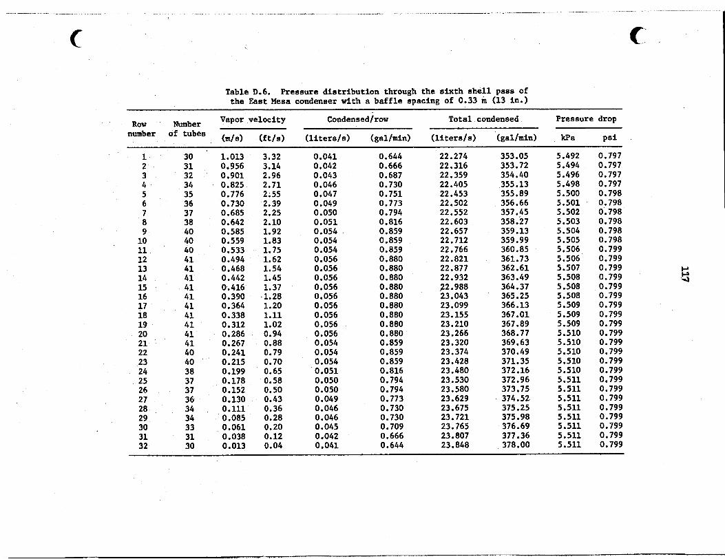
Table D.6. Pressure distribution through the sixth shell pass of the East Mesa condenser with a baffle spacing of 0.33 m (13 in.)
Vapor velocity Condensedlrow Total condensed Pressure drop Row Number number of tubes (m/s) (ft/s) (liters/s) (gal/min) (liters/s) (gal/min) kPa Psi
1 2 3 4 5 6 7
9 10 11 12 13 14 15 16 17
19 20 21 22 23 24 25 26 27
29 30 31 32
a
ia
28
30 31 32 34 35 36 37
40 40
41 41 41 41 41 41 41 41 41 41 40 40
37 37 36 34 34 33 31 30
38
40
38
1.013 3.32 0.956 3.14 0.901 2.96
0.776 2.55 0.730 2.39
0.642 2.10
0.825 2.71
0.685 2.25
0.585 1.92 0.559 1.83
0.468 1.54
0.390 .1.2a
0.338 1.11
0,286 0.94 0.267 0.88
0.533 1.75 0.494 1.62
0.442 1.45 0.416 1.37
0.364 1.20
0.312 1.02
0.241 0.79 0.215 0.70 0.199 0.65
0.152 0.50 0.130 0.43 0.111 0.36
0.061 0.20
0.013 0.04
0.178 0.58
0.085 0.28
0.038 0.12
0.041 0.042 0.043 0.046 0.047 0.049 0.050 0.051 0.054 . 0.054 0.054 0.056 0.056 0.056 0.056 0.056 0.056 0.056 0.056 0.056 0.054 0.054 0.054 0.051 0,050 0.050 0.049 0.046 0.046 0.045 0.042 0.041
0.644 0.666
0.730 0.751 0.773 0.794
0.687
0. a16 0 . a59 0 . a59 0.859 0. aao 0 . aao 0 . aao 0 . aao 0. aao 0. aao 0 . aao 0.880 0 . aao 0.859 0.859 0 . a59 0 . a16 0.794 0.794 0.773 0.730 0.730 0.709 0.666 0.644
22.274 22.316 22.359 22.405 22.453 22.502 22.552 22.603 22.657 22.712 22.766 22.821 22.877
92.988 22.932
23.043 23.099 23.155 23.210 23.266 23.320 23.374 23.428 23.480
23.580 23.530
23.629 23.675 23.721 23.765 23. a07 23. a48
353.05 353.72 354.40 355.13 355. a9 356.66 357.45 358.27 359.13 359.99 360. a5 361.73 362.61 363.49 364.37 365.25 366.13 367.01 367 .a9 368.77 369.63 370.49 371.35 372.16 372.96 373.75 374.52 375.25
376.69 377.36
375.98
378.00
5.492 0.797 5.494 0.797 5.496 0.797 5.498 0.797 5.500 0.798 5.501 0.798 5.502 0.798 5.503 0.798 5.504 0.798 5.505 0.798 5.506 0.799 5.506 0.799 5.507 0.799 5.508 0.799 5.508 0.799 5.508 0.799 5.509 0.799 5.509 0.799 5.509 0.799 5.510 0.799 5.510 0.799 5.510 0.799 5.510 0.799 5.510 0.799 5.511 0.799 5.511 0.799 5.511 0.799 5.511 0.799 5.511 0.799 5.511 0.799 5.511 0.799 5.511 0.799


ORNL/.TM-8100 Distribution Category UC-66d
INTERNAL DISTRIBUTION
1. H, G. Arnold 39-58. G. H. Llewellyn 2. J. P. Belk 59. R. H. Lyon (Consultant) 3. H. P. Blanco 60, K. H. Luk 4. D. D. Cannon 61. R. E. MacPherson 5. R. S. Carlsmith 62. H. A, McClain 6. F. C. Chin 63. V. C. Mei 7. J. H. Clinton 64-73. J. W. Mchel 8. S. K. Combs 74. S. L. Milora 9. K. D. Cook 75. L. I. Moss 10. L, M. Cuddy 76. R. W. Murphy 11. R. C. Devault 77. B. Neimann 12. N. Doming0 78. G. K. Oppegard 13. D. M. Eissenberg 79. J. A. Parsons 14. J. F. Fourman 80. F. S. Patton 15. W. Fulkerson 81. F. J. Peretz 16. W. R. Gambill 82, T. W. Pickel 17. R. W. Glass 83, A. W. Reed 18. R. E. Goodson (Consultant) 84, W. R. Reed 19. G. Grossman 85. R. C. Robertson 20. G. R. Hadder 86. M. W. Rosenthal 21. C. V. Hardin 87. T. H. Row 22. V. 0. Haynes 88.' J. A. Seneker 23. J. L. Heck 89-93. M. Siman-Tov 24. M. V. Helfrich 94. C. B. Smith 25. L. C. Hensley 95. D. G. Thomas 26. R. F. Hibbs 96. D. B. Trauger 27. H. W. Hoffman 97. H. E, Trammel1 28. R. M. Holmes 98. E, A. Vinyard 29. L. N. Howell 99. G. C. Wei 30. W. D. Hoyle 100. J. T. Weir 31. W. P. Huxtable 101. J. W. Wells 32. L. Jung 102. T. Whitus 33. R. A. Just 103. L. V. Wilson 34. A. A. Khan 104. ORNL Patent Office 35. D. J. Kincaid 105-107. Central Research Library 36. E. H. Krieg 108. Document Reference Section 37. T. R. LaPorte (Consultant) 109-1 Laboratory Records Department 38. B. Lieberman 1 Laboratory Records (RC)
119

112.
113.
114.
115.
116.
117.
118.
119.
120.
121.
122.
123.
124.
125.
126.
127.
128.
129.
130.
131.
132.
133.
134.
135.
EXTERNAL DISTRIBUTION
A. A. Adduci, DOE, San Francisco Operations Office, 133 Broadway, Oakland, CA 94612 J. H. Anderson, Sea Solar Power, Inc., 2422 South Queen Street, York, PA, 17403 W. Aung, Division of Engineering, National Science Foundation, Washington, DC 20550 K. J. Bell, School of Chemical Engineering, Oklahoma State University, Sttllwater, OK 74074 A. E. Bergles, Department of Mechanical Engineering, Iowa State University, Ames, IA 50010 C. H. Bloomster, Battelle-Pacific Northwest Laboratory, Richland, WA 99352 G. E. Brandvold, Sandia Laboratories, P. 0. Box 5800, Albuquer- que, NM 87115 E. S. Burcher, Division of Ocean Energy Technology, DOE, Forrestal Building, 1000 Independence Avenue SW, Washington, DC 20585 T. Carnavos, Noranda Metal Industries, Prospect Drive, Newton, CT 06470 N. R. Clevinger, Wolverine Division, 2100 Market St. SE, P. E. Box 2202, Decatur, AL 35601 R. L. bit, Electric Power Research Institute, P. 0. Box 10412, Palo Al to , CA 94303 N. M. F. Conover, Radian Corporation, P. 0. Box 9948, Austin, TX 78766 R. B. Coryell, Geothermal Program, National Science Foundation, Washington, DC 20550 R. H. Dart, Idaho National Engineering Laboratory, Idaho Falls, ID 83415 0. J. Demuth, Idaho National Engineering Laboratory, Idaho Falls, ID 83415 R. L. Fulton, Lawrence Berkeley Laboratory, University of California, Berkeley, CA 94720 C. G. Gottsman, Union Carbide, Linde Division, P. 0. Box 44, Tonawanda, NY 14150 T. C. Hinrichs, Magma Power Company, 5143 Sunset Blvd., LO8 Angeles, CA 92112 B. Hwang, Mail Code 2722, David Taylor Naval Ship RSID Center, Annapolis, MD 21402 I. J. Ingvarsson, Aerojet Nuclear Company, 550 Second Street, Idaho Falls, ID 83401 B. A. Johnson, Battelle-Pacific Northwest Laboratory, P. 0. Box 999, Richland, WA 99352 E. G. Keshock, Aerospace and Mechanical Engineering Department, University of Tennessee, Knoxville, TN 37916 J. Kestin, Division of Engineering, Brown University, Box D, Providence, RI 02912 G. A. Kolstad, Office of Energy Research, DOE, Washington, DC 20545

121
136.
137.
138.
139.
140.
141.
142.
143.
144.
145. 146.
147.
148.
149.
150 . 151.
152.
153.
154 . 155. 156.
157
158.
159.
160.
161.
162.
R. Kornbau, David Taylor Naval Ship Research and Development Center, Annapolis, MD 21402 J. T. Kuwada, Rogers Engineering Company, Inc., 111 Pine Street, Sixth Floor, San Francisco, CA 94111 A. D. K. Laird, Mechanical Engineering Department, University of California, Lawrence Berkeley Laboratory, Berkeley, CA 94720 R. J. LaSala, Geothermal and Hydro Power Division, Department of Energy, 1000 Independence Avenue SW, Washington, DC 20585 A. Lavi, Department of Chemical Engineering, Carnegie-Mellon University, Schenley Park, Pittsburgh, PA 15213 G. W. Leonard, ATDD (P&E) HPDD, Department of the Navy, China Lake, CA 93555 R. Letan, Ben-Gurion University of the Negev, Department of Mechanical Engineering, P. 0. Box 653, Beer Sheva, Israel A. Lundberg, L-505, University of California, Lawrence Livermore Laboratory, P. 0. Box 808, Livermore, CA 94550 W. W. Madsgn, Idaho National Engineering Laboratory, Idaho Falls, ID 83415 P. H. McCabe, Route 1, Bedo, ID 83323 C. McFarland, Solar Research and Technology, Department of Energy, 1000 Independence Avenue SW, Washington, DC 20585 G. Mines, Idaho National Engineering Laboratory, Idaho Falls, ID 83415 P. E. Minton, Union Carbide, P. 0. Box 8361, Bldg. 2000, S. Charleston, W. VA 25303 K. Mirk, Lawrence Berkeley Laboratory, University of California, Berkeley, CA 94720 W. C. Moore, York Division, Borg Warner Corporation, York, PA 17403 D. T. Neil, Idaho National Engineering Laboratory, Idaho Falls, ID 83415 K. Nichols, Barber-Nichols Engineering, 6325 West 55th Avenue, Arvada, CO 80002 F. Notaro, Union Caltbide, Linde Division, P. 0. Box 44, Tonawanda, NY 14150 J. Nugent, Geothermal Energy, San Diego Gas and Electric Company, P. 0. Box 1831, San Diego, CA 92112 R. H. Nunn, Naval Postgraduate School, Monterey, CA 93940 R. Olander, Barber-Nichols Engineering, 6325 West 55th Avenue, Arvada, CO 80002 P. 0. O'Neil, Union Carbide, Linde Division, P. 0. Box 44, Tonawanda, NY 14150 W. L. Owens, Lockheed Missiles and Space Company, Inc., P. 0. Box 504, Sunnyvale, CA 95088 R. W. Perkins, Spiral Tubing Corporation, 533 John Downey Drive, New Britain, CT 06051 J. J. Perona, Chemical and Metallurgical Engineering Department, University of Tennessee, Knoxville, TN 37916 G. Phillips, Barber-Nichols Engineering, 6325 West 55th Avenue, Arvada, CO 80002 W. L. Pope, Lawrence Berkeley Laboratory, University of California, Berkeley, CA 94720
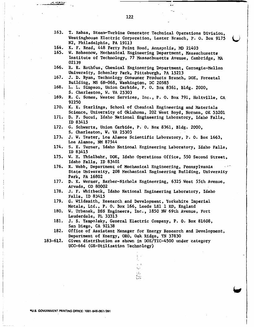
i
163.
164. 165.
166.
167.
168.
169.
170.
171.
172.
173.
174.
175.
T. Rabas, Steam-Turbine Generator Technical Operations Division, Westinghouse Electric Corporation, Lester Branch, P. 0 , Box 9175 N2, Philadelphia, PA 19113 R. F. Read, 448 Ferry Point Road, Annapolis, Mn 21403 W. Rohsenow, Mechanical Engineering Department, Massachusetts Institute of Technology, 77 Massachusetts Avenue, Cambridge, MA 02139 R. R. Rothfus, Chemical Engineering Department, Carnegie-Mellon University, Schenley Park, Pittsburgh, PA 15213 J. D. Ryan, Technology Consumer Products Branch, DOE, Forestal Building, MS 6H-068, Washington, DC 20585 L. L. Simpson, Union Carbide, P. 0. Box 8361, Bldg. 2000, S. Charleston, W. VA 25303 R. C. Somes, Westec Services, Inc., P, 0. Box 791, Holtville, CA 92250 K. E. Starlings, School of Chemical Engineering; and Materials Science, University of Oklahoma, 202 West Boyd, Norman, OK 53201 D. F. Sucui, Idaho National Engineering Laboratory, Idaho Falls, ID 83415 G. Schwartz, Union Carbide, P. 0. Box 8361, Bldg. 2000, S. Charleston, W. VA 25303 J. W. Tester, Los Alamos Scientific Laboratory, P. 0. Box 1663, L o s Alamos, NM 87544 S. E. Turner, Idaho National Engineering Laboratory, Idaho Falls, ID 83415 W. H. Thielbahr, DOE, Idaho Operations Office, 550 Second Street, Idaho Falls, ID 83401
176. R. Webb, Department of Mechanical Engineering, Pennsylvania - State University, 208 Mechanical Engineering Building, University Park, PA 16802
Arvada, CO 80002
Falls, ID 83415 G. Wildsmith, Research and Development, Yorkshire Imperial Metals, Ltd., P. 0. Box 166, Leeds LS1 1 RD, England W. Urbanek, DSS Engineers, Inc., 1850 NW 69th Avenue, Fort Lauderdale, FL 33313 J. S. Yampolsky, General Electric Company, P. 0. Box 81608, San Diego, CA 92138 Office of Assistant Manager for Energy Research and Development, Department of Energy, ORO, Oak Ridge, TN 37830 Given distribution as shown in DOE/TIC-4500 under category UCC-66d (GE-Ut iliza t ion Technology )
177. D. K. Werner, Barber-Nichols Engineering, 6325 West 55th Avenue,
178. J. F. Whitbeck, Idaho National Engineering Laboratory, Idaho
179.
180.
181.
182.
183-612.
W.S. GOVERNMENT PRINTING OFFICE: 1981 -646.067/391 I
b
Related Documents