5: DataLink Layer 5-1 Chapter 5: DataLink Layer Course on Computer Communication and Networks, CTH/GU The slides are adaptation of the slides made available by the authors of the course’s main textbook Computer Networking: A Top Down Approach 5 th edition. Jim Kurose, Keith Ross Addison-Wesley, 2009

5: DataLink Layer5-1 Chapter 5: DataLink Layer Course on Computer Communication and Networks, CTH/GU The slides are adaptation of the slides made available.
Dec 22, 2015
Welcome message from author
This document is posted to help you gain knowledge. Please leave a comment to let me know what you think about it! Share it to your friends and learn new things together.
Transcript

5: DataLink Layer 5-1
Chapter 5: DataLink Layer
Course on Computer Communication and Networks, CTH/GU
The slides are adaptation of the slides made available by the authors of the course’s main textbook
Computer Networking: A Top Down Approach 5th edition. Jim Kurose, Keith RossAddison-Wesley, 2009

5: DataLink Layer 5-2
Chapter 5: The Data Link Layer
Our goals: understand principles behind data link layer
services: error detection, correction sharing a broadcast channel: multiple access link layer addressing reliable data transfer, flow control: done!
instantiation and implementation of various link layer technologies
data-link layer has responsibility of transferring frames from one node to adjacent node over a link

5: DataLink Layer 5-3
Link Layer
5.1 Introduction and services
Framing 5.2 Error detection
and correction 5.3Multiple access
protocols
LAN technology 5.5 Ethernet 5.6 Interconnection 5.4 Link-Layer
Addressing 5.7 PPP 5.9 A day in the life of
a web request(5.8 Link Virtualization:
ATM and MPLS)
5: DataLink Layer 5-4
Link layer: context Datagram transferred by different
link protocols over different links: e.g., Ethernet on first link, frame
relay on intermediate links, 802.11 on last link
Each link protocol provides different services
e.g., may or may not provide rdt over link
transportation analogy trip from Princeton to
Lausanne limo: Princeton to JFK plane: JFK to Geneva train: Geneva to Lausanne
tourist = datagram transport segment =
communication link transportation mode = link
layer protocol travel agent = routing
algorithm

5: DataLink Layer 5-5
Where is the link layer implemented?
in each and every host link layer implemented
in “adaptor” (aka network interface card NIC) Ethernet card, 802.11 card implements link, physical
layer
attaches into host’s system buses
combination of hardware, software, firmware
controller
physicaltransmission
cpu memory
host bus (e.g., PCI)
network adaptercard
host schematic
applicationtransportnetwork
link
linkphysical
5: DataLink Layer 5-6
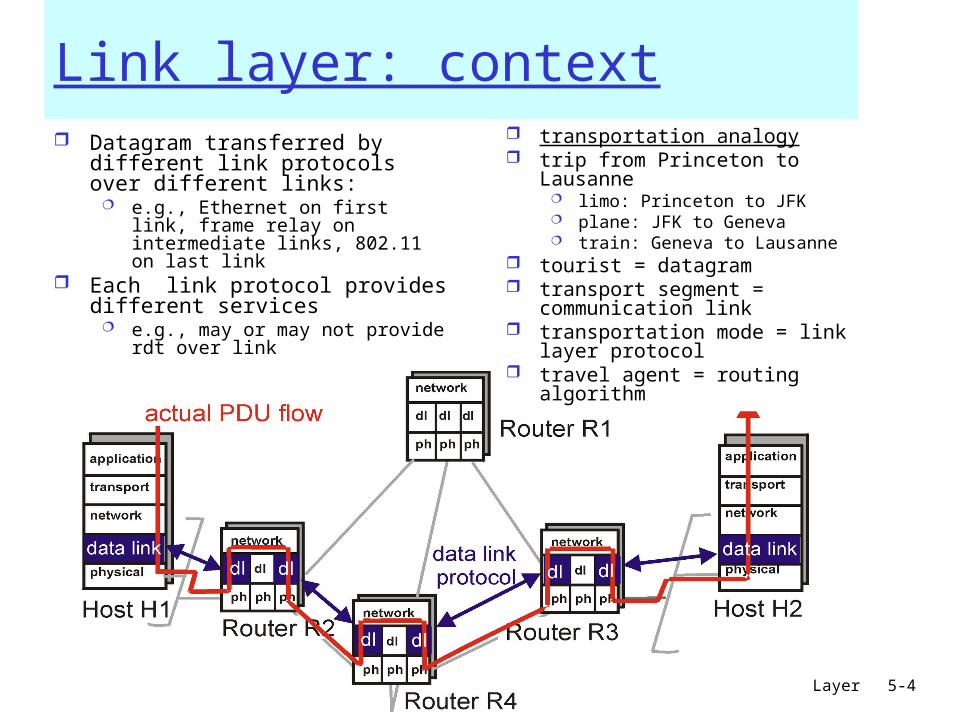
Adaptors Communicating
sending side: encapsulates datagram
in frame adds error checking bits,
rdt, flow control, etc.
receiving side looks for errors, rdt, flow
control, etc extracts datagram, passes
to upper layer at receiving side
controller controller
sending host receiving host
datagram datagram
datagram
frame

5: DataLink Layer 5-7
Link Layer Services Framing, link access:
encapsulate datagram into frame, adding header, trailer channel access if shared medium “MAC” addresses used in frame headers to identify source,
dest • different from IP address!
Reliable delivery between adjacent nodes, flow ctrl Control when errors + pace between adjacent sending and
receiving nodes• we learned how to do this already (chapter 3)!
seldom used on low bit error link (fiber, some twisted pair) wireless links: high error rates Q: why both link-level and end-end reliability?
5: DataLink Layer 5-8
Link Layer Services (more)
Error Detection: errors caused by signal attenuation, noise. receiver detects presence of errors:
• signals sender for retransmission or drops frame
Error Correction: receiver identifies and corrects bit error(s) without
resorting to retransmission

5: DataLink Layer 5-9
Link Layer
5.1 Introduction and services
Framing 5.2 Error detection
and correction 5.3Multiple access
protocols
LAN technology 5.5 Ethernet 5.6 Interconnection 5.4 Link-Layer
Addressing 5.7 PPP 5.9 A day in the life of
a web request(5.8 Link Virtualization:
ATM and MPLS)
5: DataLink Layer 5-10
Framing
to detect possible bit stream errors in the physical layer, the data link layer groups bits from the network layer into discrete frames
the receiver must be able to detect the beginning and the end of the frame
Example methods: Clock-based + Character count : physical-
clock synchronization: much dependent on clock drifts + the counter could be garbled up during transmission

5: DataLink Layer 5-11
Byte Stuffingflag bytepatternin datato send
flag byte pattern plusstuffed byte in transmitted data
<01111110> delimits beginning, end of frame
“data transparency”: data field must be allowed to include <01111110> Q: is received
<01111110> data or flag?
Sender: adds (“stuffs”) extra <01111110> byte after each <01111110> data byte
Receiver: two 01111110 bytes
in a row: discard first byte, continue data reception
single 01111110: flag byte
5: DataLink Layer 5-12
Framing techniques: examples (cont)
... Physical layer coding violation:
exploits special encodings at the physical layer, e.g. Manchester encoding (see next …)

5: DataLink Layer 5-13
Encoding
Problem: Simple binary encoding (aka Non-Return to Zero, NRZ) introduces problems:
consecutive 0’s or 1’s can lead to a situation called baseline wander (hard to distinguish signal values)
hard to recover the clock
More robust encoding: Manchester: XOR NRZ with clock

5: DataLink Layer 5-14
Link Layer
5.1 Introduction and services
Framing 5.2 Error detection
and correction 5.3Multiple access
protocols
LAN technology 5.5 Ethernet 5.6 Interconnection 5.4 Link-Layer
Addressing 5.7 PPP 5.9 A day in the life of
a web request(5.8 Link Virtualization:
ATM and MPLS)

5: DataLink Layer 5-15
Error DetectionEDC= Error Detection and Correction bits (redundancy)D = Data protected by error checking, may include header fields
• Error detection not 100% reliable!• protocol may miss some errors, but this should happen only rarely• larger EDC field yields better detection and correction
5: DataLink Layer 5-16
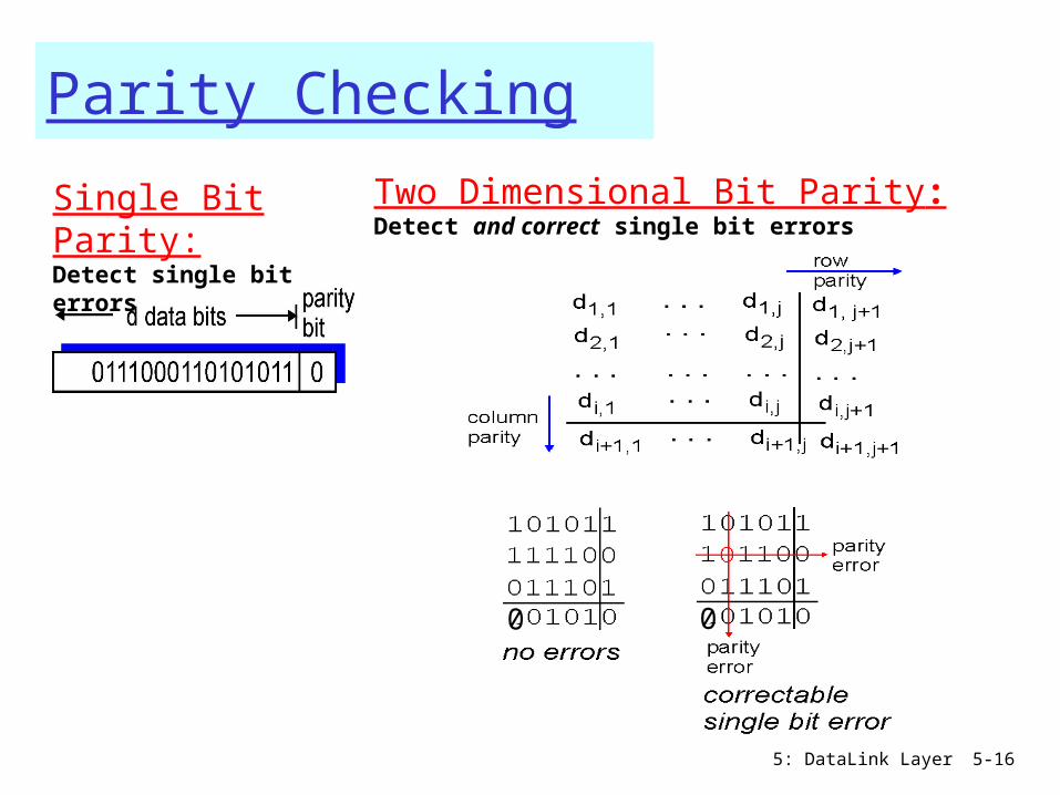
Parity Checking
Single Bit Parity:Detect single bit errors
Two Dimensional Bit Parity:Detect and correct single bit errors
0 0

5: DataLink Layer 5-17
Internet checksums
TCP (UDP)’s checksum:
segment contents = sequence of 16-bit integers
checksum: addition (1’s complement sum) of segment contents
sender puts checksum value into UDP (TCP) checksum field
Cyclic redundancy check (CRC)• data bits, D = binary number consider r+1 bit pattern (generator),
G goal: compute r CRC bits, R, such that
<D,R> exactly divisible by G (modulo 2)
receiver knows G, divides <D,R> by G. If non-zero remainder: error detected!
can detect errors on less than r+1 bits
International standards for G (CRC polynomials)

5: DataLink Layer 5-18
CRC ExampleRecall we want:
D.2r XOR R = nGequivalently:
if we divide D.2r by G, want remainder R
R = remainder[ ]D.2r
G
5: DataLink Layer 5-19
Link Layer
5.1 Introduction and services
Framing 5.2 Error detection
and correction 5.3Multiple access
protocols
LAN technology 5.5 Ethernet 5.6 Interconnection 5.4 Link-Layer
Addressing 5.7 PPP 5.9 A day in the life of
a web request(5.8 Link Virtualization:
ATM and MPLS)

5: DataLink Layer 5-20
Multiple Access Links and Protocols
Two types of “links”: point-to-point
PPP for dial-up access point-to-point link between Ethernet switch and host
broadcast (shared wire or medium) Ethernet upstream HFC 802.11 wireless LAN
shared wire (e.g., cabled Ethernet)
shared RF (e.g., 802.11 WiFi)
shared RF(satellite)
humans at acocktail party
(shared air, acoustical)

5: DataLink Layer 5-21
Multiple Access protocols single shared broadcast channel two or more simultaneous transmissions by nodes:
interference collision if node receives two or more signals at the same
time
multiple access protocol distributed algorithm that determines how nodes
share channel, i.e., determine when node can transmit communication about channel sharing must use channel
itself! • no out-of-band channel for coordination

5: DataLink Layer 5-22
Ideal Mulitple Access Protocol
Broadcast channel of rate R bps1. When one node wants to transmit, it can send
at rate R.2. When M nodes want to transmit, each can
send at average rate R/M3. Fully decentralized:
no special node to coordinate transmissions
4. Simple
5: DataLink Layer 5-23
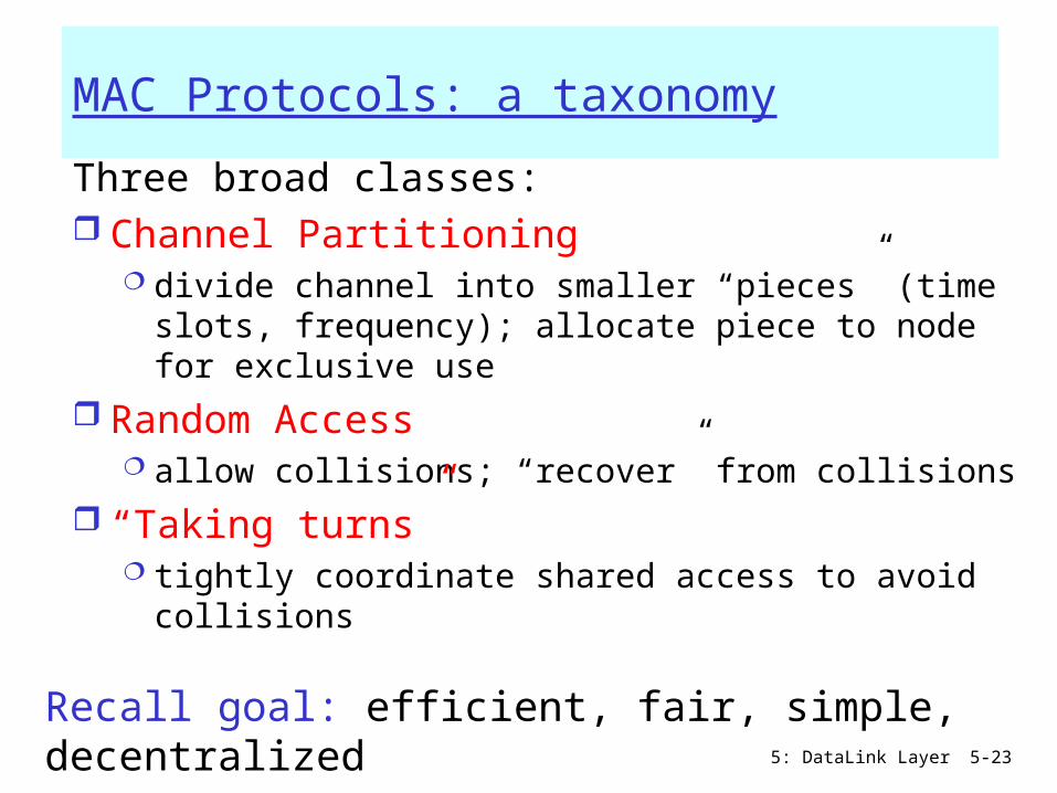
MAC Protocols: a taxonomy
Three broad classes: Channel Partitioning
divide channel into smaller “pieces” (time slots, frequency); allocate piece to node for exclusive use
Random Access allow collisions; “recover” from collisions
“Taking turns” tightly coordinate shared access to avoid
collisions
Recall goal: efficient, fair, simple, decentralized

5: DataLink Layer 5-24
Channel Partitioning MAC protocols: TDMA, FDMA
TDMA: time division multiple access
access to channel in "rounds"
each station gets fixed length slot (length = pkt trans time) in each round
unused slots go idle example: 6-station LAN,
1,3,4 have pkt, slots 2,5,6 idle
FDMA: frequency division multiple access
each station assigned fixed frequency band
unused transmission time in frequency bands goes idle example: 6-station LAN, 1,3,4
have pkt, frequency bands
2,5,6 idle fr
equ
ency
bands

5: DataLink Layer 5-25
Channel Partitioning CDMA
CDMA: Code Division Multiple Access allows each station to transmit over the entire frequency
spectrum all the time. simultaneous transmissions are separated using coding
theory. used mostly in wireless broadcast channels (cellular, satellite, etc) –
we will study it in the wireless context has been ”traditionally” used in the military
Observe:MUX = speak person-to-person in designated spaceCDMA = ”shout” using different languages: the ones who know
the language will get what you say
5: DataLink Layer 5-26
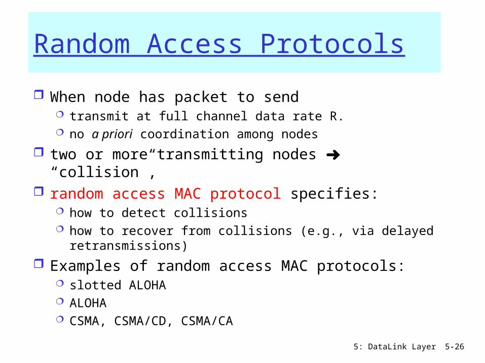
Random Access Protocols
When node has packet to send transmit at full channel data rate R. no a priori coordination among nodes
two or more transmitting nodes ➜ “collision”, random access MAC protocol specifies:
how to detect collisions how to recover from collisions (e.g., via delayed
retransmissions)
Examples of random access MAC protocols: slotted ALOHA ALOHA CSMA, CSMA/CD, CSMA/CA
5: DataLink Layer 5-27
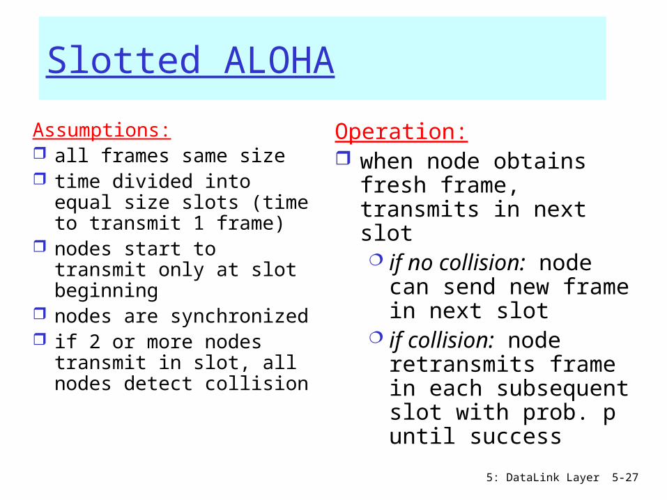
Slotted ALOHA
Assumptions: all frames same size time divided into
equal size slots (time to transmit 1 frame)
nodes start to transmit only at slot beginning
nodes are synchronized
if 2 or more nodes transmit in slot, all nodes detect collision
Operation: when node obtains fresh
frame, transmits in next slot if no collision: node
can send new frame in next slot
if collision: node retransmits frame in each subsequent slot with prob. p until success

5: DataLink Layer 5-28
Slotted ALOHA
Pros single active node can
continuously transmit at full rate of channel
highly decentralized: only slots in nodes need to be in sync
simple
Cons collisions, wasting
slots idle slots nodes may be able to
detect collision in less than time to transmit packet
clock synchronization

5: DataLink Layer 5-29
Slotted Aloha efficiency
Q: max fraction of successful transmissions?A: Suppose N stations, each transmits in slot with
probability p prob. successful transmission is:
P[specific node succeeds]= p (1-p)(N-1)
P[any of N nodes succeeds] = N p (1-p)(N-1)
Efficiency = 1/e = .37 LARGE N
At best: channeluse for useful transmissions 37%of time!
Efficiency : long-run fraction of successful slots (many nodes, all with many frames to send)
5: DataLink Layer 5-30
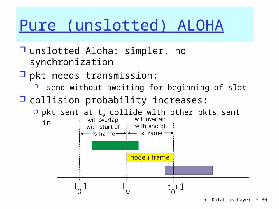
Pure (unslotted) ALOHA unslotted Aloha: simpler, no synchronization pkt needs transmission:
send without awaiting for beginning of slot
collision probability increases: pkt sent at t0 collide with other pkts sent in [t0-1,
t0+1]

5: DataLink Layer 5-31
Pure Aloha (cont.)
P(success by any of N nodes) = N p . (1-p)2N =
i.e. N p P(no other node transmits in [p0-1,p0] .
P(no other node transmits in [p0,p0+1]
=(as n -> infty …)
1/(2e) = .18
S =
thro
ughput
=
“goodput”
(
succ
ess
rate
)
G = offered load = #frames per frame-time0.5 1.0 1.5 2.0
0.1
0.2
0.3
0.4
Pure Aloha
Slotted Alohaprotocol constrainseffective channelthroughput!
5: DataLink Layer 5-32
CSMA: Carrier Sense Multiple Access
CSMA: listen before transmit: If channel sensed busy, defer transmission
back-off, random interval If/when channel sensed idle:
p-persistent CSMA: transmit immediately with probability p; with probablility 1-p retry after random interval
non-persistent CSMA: transmit after random interval
human analogy: don’t interrupt others!
5: DataLink Layer 5-33
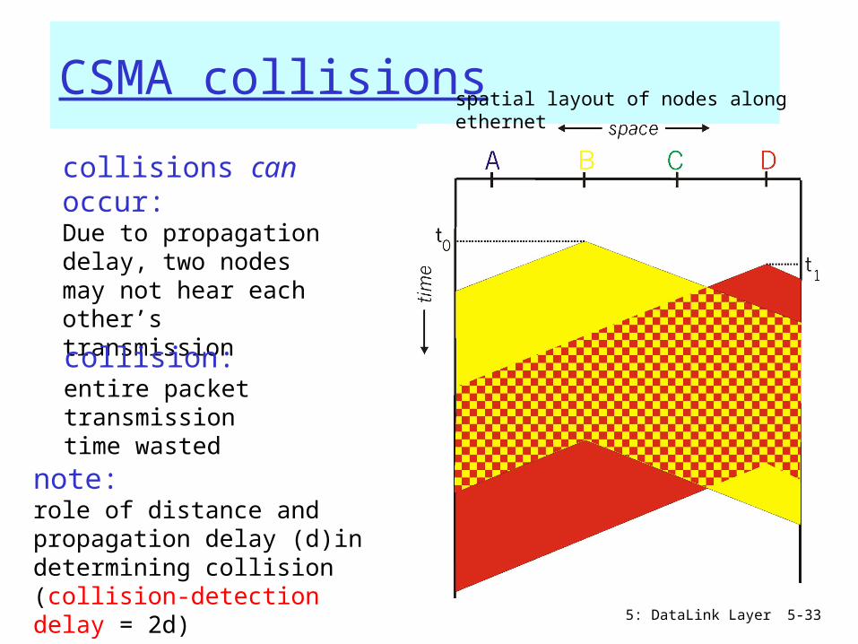
CSMA collisions
collisions can occur:Due to propagation delay, two nodes may not hear each other’s transmission
collision:entire packet transmission time wasted
spatial layout of nodes along ethernet
note:role of distance and propagation delay (d)in determining collision (collision-detection delay = 2d)

5: DataLink Layer 5-34
CSMA/CD (Collision Detection)CSMA/CD: carrier sensing, deferral as in CSMA
colliding transmissions aborted, reducing channel wastage persistent or non-persistent retransmission
collision detection: easy in wired LANs: measure signal
strengths, compare transmitted, received signals
different in wireless LANs:transmitter/receiver not “on” simultaneously; collision at the receiver matters, not the sender
human analogy: the polite conversationalist

5: DataLink Layer 5-35
“Taking Turns” MAC protocolschannel partitioning MAC protocols:
share channel efficiently and fairly at high load
inefficient at low load: delay in channel access, 1/N bandwidth allocated even if only 1 active node!
Random access MAC protocols efficient at low load: single node can fully
utilize channel high load: collision overhead
“taking turns” protocolslook for best of both worlds!

5: DataLink Layer 5-36
“Taking Turns” MAC protocols
Token passing: control token-frame passed from one node to
next sequentially. not pure broadcast concerns:
token overhead latency single point of failure (token)
5: DataLink Layer 5-37
IEEE 802.4 Standard (General Motors Token Bus)(not in must-study material)
Contention systems limitation: worst-case delay until successful transmission is unlimited => not suitable for real-time traffic
Solution: token-passing, round robin token = special control frame; only the
holding station can transmit; then it passes it to another station, i.e. for token bus, the next in the logical ring
4 priority classes of traffic, using timers Logical ring-maintenance: distributed strategy
Robust, somehow complicated though

5: DataLink Layer 5-38
IEEE Standard 802.5 (Token Ring) (not in must-study material)Motivation: instead of complicated token-bus, have a physical
ringPrinciple: Each bit arriving at an interface is copied into a 1-bit
buffer (inspected and/or modified); then copied out to the ring again. copying step introduces a 1-bit delay at each interface.

5: DataLink Layer 5-39
Token Ring operation
to transmit a frame, a station is required to seize the token and remove it from the ring before transmitting.
bits that have propagated around the ring are removed from the ring by the sender (the receiver in FDDI).
After a station has finished transmitting the last bit of its frame, it must regenerate the token.
5: DataLink Layer 5-40
IEEE 802.5 Ring: Maintenance (not in must-study material)
Centralised: a “monitor” station oversees the ring:
generates token when lost cleans the ring when garbled/orphan frames
appear
If the monitor goes away, a convention protocol ensures that another station is elected as a monitor (e.g. the one with highest identity)
If the monitor gets ”mad”, though…..

5: DataLink Layer 5-41
IEEE 802.5 Ring: Priority Algorithm (not in must-study material)
Station Supon arrival of frame f:
set prior(f) := max{prior(f), prior(S)} forward(f)
upon arrival of Tif prior(T)>prior(S) then forward(T)else send own frame f with prior(f):=0
wait until f comes backprior(T):=prior(f)forward(T)

5: DataLink Layer 5-42
Reservation-based protocolsDistributed Polling – Bit-map protocol: time divided into slots begins with N short reservation slots
station with message to send posts reservation during its slot
reservation seen by all stations reservation slot time equal to channel end-end
propagation delay (why?) after reservation slots, message transmissions ordered by
known priority
5: DataLink Layer 5-43
Summary of MAC protocols
What do you do with a shared media? Channel Partitioning, by time, frequency or
code• Time Division, Frequency Division
Random partitioning (dynamic), • ALOHA, S-ALOHA, CSMA, CSMA/CD• carrier sensing: easy in some technologies (wire),
hard in others (wireless)• CSMA/CD used in Ethernet• CSMA/CA used in 802.11
Taking Turns• polling, token passing• Bluetooth, FDDI, IBM Token Ring

5: DataLink Layer 5-44
Link Layer
5.1 Introduction and services
Framing 5.2 Error detection
and correction 5.3Multiple access
protocols
LAN technology 5.5 Ethernet 5.6 Interconnection 5.4 Link-Layer
Addressing 5.7 PPP 5.9 A day in the life of
a web request(5.8 Link Virtualization:
ATM and MPLS)

5: DataLink Layer 5-45
Ethernet
“dominant” wired LAN technology: cheap $20 for 100Mbs! first widely used LAN technology Simpler, cheaper than token LANs and ATM Kept up with speed race: 10 Mbps – 10 Gbps
Metcalfe’s Ethernetsketch
5: DataLink Layer 5-46
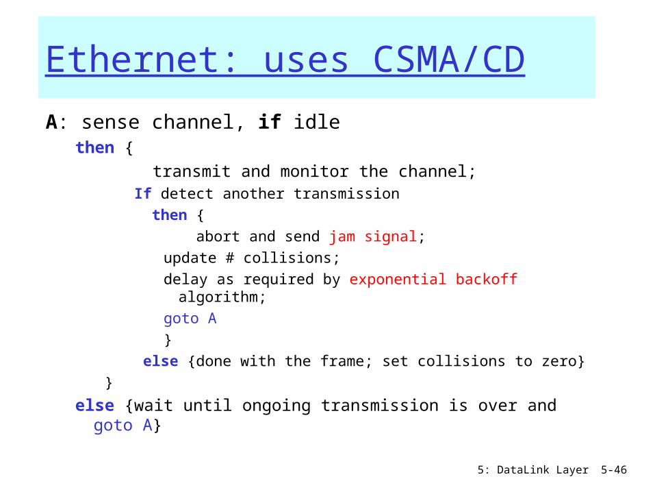
Ethernet: uses CSMA/CD
A: sense channel, if idle then {
transmit and monitor the channel; If detect another transmission then { abort and send jam signal;
update # collisions; delay as required by exponential backoff algorithm; goto A}
else {done with the frame; set collisions to zero}}
else {wait until ongoing transmission is over and goto A}
5: DataLink Layer 5-47
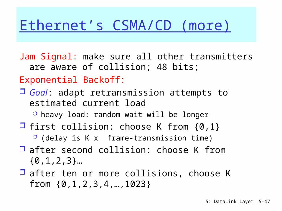
Ethernet’s CSMA/CD (more)
Jam Signal: make sure all other transmitters are aware of collision; 48 bits;
Exponential Backoff: Goal: adapt retransmission attempts to
estimated current load heavy load: random wait will be longer
first collision: choose K from {0,1} (delay is K x frame-transmission time)
after second collision: choose K from {0,1,2,3}…
after ten or more collisions, choose K from {0,1,2,3,4,…,1023}

5: DataLink Layer 5-48
Recall: collision detection interval = 2*Propagation delay along the LAN
This implies a minimum frame size and/or a maximum wire length
Critical factor:a = 2 * propagation_delay /frame_transmission_delay
Ethernet (CSMA/CD) Limitation
5: DataLink Layer 5-49
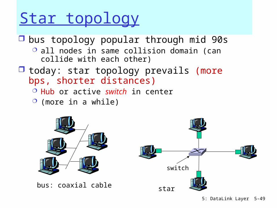
Star topology bus topology popular through mid 90s
all nodes in same collision domain (can collide with each other)
today: star topology prevails (more bps, shorter distances) Hub or active switch in center (more in a while)
switch
bus: coaxial cable star
5: DataLink Layer 5-50
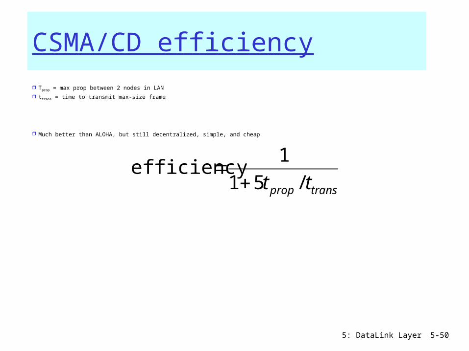
CSMA/CD efficiency
Tprop = max prop between 2 nodes in LAN
ttrans = time to transmit max-size frame
Much better than ALOHA, but still decentralized, simple, and cheap
transprop tt /51
1efficiency
5: DataLink Layer 5-51
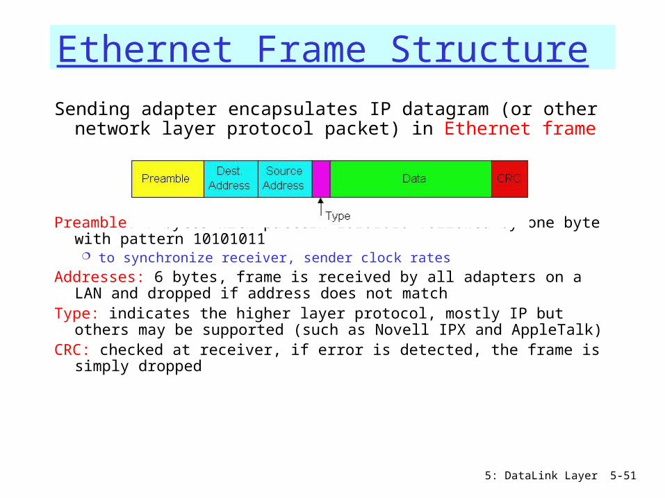
Ethernet Frame Structure
Sending adapter encapsulates IP datagram (or other network layer protocol packet) in Ethernet frame
Preamble: 7 bytes with pattern 10101010 followed by one byte with pattern 10101011 to synchronize receiver, sender clock rates
Addresses: 6 bytes, frame is received by all adapters on a LAN and dropped if address does not match
Type: indicates the higher layer protocol, mostly IP but others may be supported (such as Novell IPX and AppleTalk)
CRC: checked at receiver, if error is detected, the frame is simply dropped
5: DataLink Layer 5-52
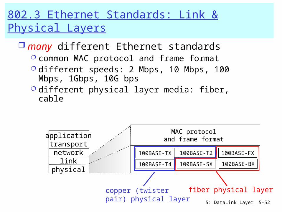
802.3 Ethernet Standards: Link & Physical Layers
many different Ethernet standards common MAC protocol and frame format different speeds: 2 Mbps, 10 Mbps, 100
Mbps, 1Gbps, 10G bps different physical layer media: fiber, cable
applicationtransportnetwork
linkphysical
MAC protocoland frame format
100BASE-TX
100BASE-T4
100BASE-FX100BASE-T2
100BASE-SX 100BASE-BX
fiber physical layercopper (twisterpair) physical layer

5: DataLink Layer 5-53
Manchester encoding
Used in 10BaseT Each bit has a transition Allows clocks in sending and receiving nodes to
synchronize to each other no need for a centralized, global clock among nodes!
Hey, this is physical-layer stuff!
5: DataLink Layer 5-54
Ethernet: Unreliable, connectionless connectionless: No handshaking between sending
and receiving NICs unreliable: receiving NIC doesn’t send acks or
nacks to sending NIC stream of datagrams passed to network layer can have
gaps (missing datagrams) gaps will be filled if app is using TCP otherwise, app will see gaps

5: DataLink Layer 5-55
Link Layer
5.1 Introduction and services
Framing 5.2 Error detection
and correction 5.3Multiple access
protocols
LAN technology 5.5 Ethernet 5.6 Interconnection 5.4 Link-Layer
Addressing 5.7 PPP 5.9 A day in the life of
a web request(5.8 Link Virtualization:
ATM and MPLS)

5: DataLink Layer 5-56
Interconnecting with hubsHubs are essentially physical-layer repeaters:
bits coming from one link go out all other links at the same rate (no frame buffering)
no CSMA/CD at hub: adapters detect collisions (one large collision domain)
provides net management functionality (monitoring, statistics) Extends distance between nodes Can’t interconnect e.g. 10BaseT & 100BaseT
hub
hubhub
hub

5: DataLink Layer 5-57
Switch: allows multiple simultaneous transmissions
hosts may have dedicated, direct connection to switch
switches buffer packets Ethernet protocol used on
each incoming link, but no collisions; full duplex each link is its own collision
domain switching: A-to-A’ and B-
to-B’ simultaneously, without collisions not possible with dumb hub
A
A’
B
B’
C
C’
switch with six interfaces(1,2,3,4,5,6)
1 23
45
6

5: DataLink Layer 5-58
Switches (bridges): cont. Link Layer devices: operate on frames, examining header
and selectively forwarding frame based on its destination filtering: same-LAN-segment frames not forwarded to other seg’s
Advantages: Isolates collision domains:
• higher total max throughput• no limit on number of nodes nor distances
Can connect different net-types (translational, …) Transparent: no need for any change to hosts LAN adapters
forwarding: how to know LAN segment on which to forward frame? looks like a routing problem…
switch

5: DataLink Layer 5-59
Switch: self-learning
switch learns which hosts can be reached through which interfaces when frame received,
switch “learns” location of sender: incoming LAN segment
records sender/location pair in switch table
A
A’
B
B’
C
C’
1 23
45
6
A A’
Source: ADest: A’
MAC addr interface TTL
Switch table (initially empty)
A 1 60

5: DataLink Layer 5-60
Switch: frame filtering/forwardingWhen frame received:
1. record link associated with sending host2. index switch table using MAC dest address3. if entry found for destination
then { if dest on segment from which frame arrived
then drop the frame else forward the frame on interface indicated } else flood
forward on all but the interface on which the frame arrived
5: DataLink Layer 5-61
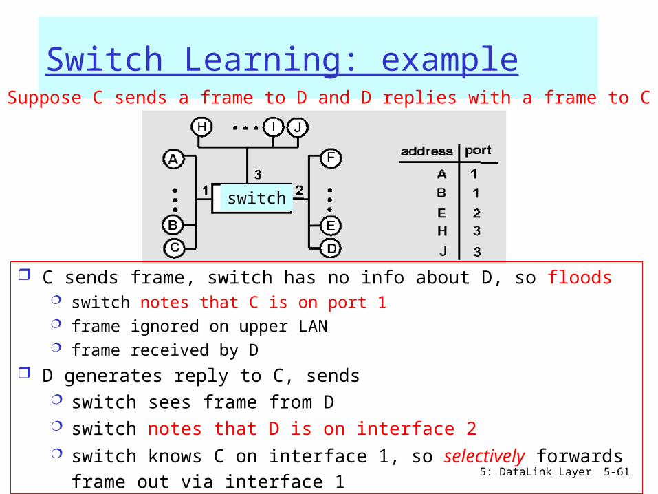
Switch Learning: exampleSuppose C sends a frame to D and D replies with a frame to C
C sends frame, switch has no info about D, so floods switch notes that C is on port 1 frame ignored on upper LAN frame received by D
D generates reply to C, sends switch sees frame from D switch notes that D is on interface 2 switch knows C on interface 1, so selectively forwards frame
out via interface 1
switch

5: DataLink Layer 5-62
Switch: traffic isolation switch installation breaks subnet into LAN
segments switch filters packets:
same-LAN-segment frames not usually forwarded onto other LAN segments
segments become separate collision domains
hub hub hub
switch
collision domain collision domain
collision domain

5: DataLink Layer 5-63
Switches vs. Routers both store-and-forward devices
routers: network layer devices (examine network layer headers) Switches (bridges) are Link Layer devices
routers maintain routing tables, implement routing algorithms
switches maintain filtering tables, implement filtering, learning (and spanning tree) algorithms
Switch

5: DataLink Layer 5-64
Routers vs. Bridges/Switches
Bridges/Switches+ Bridge operation is
simpler requiring less processing bandwidth
- Topologies are restricted with bridges (a spanning tree must be built to avoid cycle)
- Bridges do not offer protection from broadcast storms (endless broadcasting by a host will be forwarded by a bridge)
Routers+ arbitrary topologies can be
supported, cycling is limited by good routing protocols
+ provide firewall protection against broadcast storms
- require detailed configuration (not plug and play) and higher processing capacity
Bridges/switches do well in small (few hundred hosts) while routers used in large networks (thousands of hosts)
5: DataLink Layer 5-65
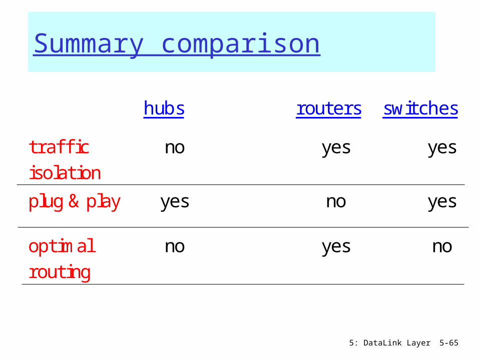
Summary comparison
hubs routers switches
traffi c isolation
no yes yes
plug & play yes no yes
optimal routing
no yes no
cut through
yes no yes

5: DataLink Layer 5-66
Institutional network
to externalnetwork
router
IP subnet
mail server
web server

5: DataLink Layer 5-67
VLANs: motivation
What happens if: CS user moves office to
EE, but wants connect to CS switch?
single broadcast domain: all layer-2 broadcast
traffic (ARP, DHCP) crosses entire LAN (security/privacy, efficiency issues)
each lowest level switch has only few ports in use
Computer Science Electrical
Engineering
ComputerEngineering
What’s “wrong” with this picture?

5: DataLink Layer 5-68
VLANs Port-based VLAN: switch ports grouped (by switch management software) so that single physical switch ……
Switch(es) supporting VLAN capabilities can be configured to define multiple virtual LANS over single physical LAN infrastructure.
Virtual Local Area Network
1
8
9
16102
7
…
Electrical Engineering(VLAN ports 1-8)
Computer Science(VLAN ports 9-15)
15
…
Electrical Engineering(VLAN ports 1-8)
…
1
82
7 9
1610
15
…
Computer Science(VLAN ports 9-16)
… operates as multiple virtual switches

5: DataLink Layer 5-69
Port-based VLAN:
1
8
9
16102
7
…
Electrical Engineering(VLAN ports 1-8)
Computer Science(VLAN ports 9-15)
15
…
traffic isolation: frames to/from ports 1-8 can only reach ports 1-8 can also define VLAN based on
MAC addresses of endpoints, rather than switch port
dynamic membership: ports can be dynamically assigned among VLANs
router
forwarding between VLANS: done via routing (just as with separate switches) in practice vendors sell
combined switches plus routers

5: DataLink Layer 5-70
VLANS spanning multiple switches
trunk port: carries frames between VLANS defined over multiple physical switches frames forwarded within VLAN between switches can’t be
vanilla 802.1 frames (must carry VLAN ID info) 802.1q protocol adds/removed additional header fields
for frames forwarded between trunk ports
1
8
9
102
7
…
Electrical Engineering(VLAN ports 1-8)
Computer Science(VLAN ports 9-15)
15
…
2
73
Ports 2,3,5 belong to EE VLANPorts 4,6,7,8 belong to CS VLAN
5
4 6 816
1

5: DataLink Layer 5-71
Type
2-byte Tag Protocol Identifier (value: 81-00)
Tag Control Information (12 bit VLAN ID field,
3 bit priority field like IP TOS)
Recomputed CRC
802.1Q VLAN frame format
802.1 frame
802.1Q frame
5: DataLink Layer 5-72
Link Layer
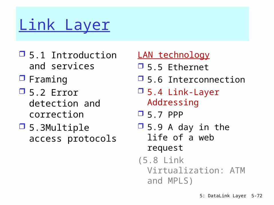
5.1 Introduction and services
Framing 5.2 Error detection
and correction 5.3Multiple access
protocols
LAN technology 5.5 Ethernet 5.6 Interconnection 5.4 Link-Layer
Addressing 5.7 PPP 5.9 A day in the life of
a web request(5.8 Link Virtualization:
ATM and MPLS)

5: DataLink Layer 5-73
LAN Addresses32-bit IP address: network-layer address used to get datagram to destination network (recall
IP network definition)
LAN (or MAC or physical) address: to get datagram from
one interface to another physically-connected interface (same network)
48 bit MAC address (for most LANs)burned in NIC’s ROM(sometimes resettable)
Broadcast address =FF-FF-FF-FF-FF-FF

5: DataLink Layer 5-74
LAN Address (more)
MAC address allocation administered by IEEE manufacturer buys portion of MAC address space (to
assure uniqueness)
Analogy: (a) MAC address: like People’s Names or
PersonalNum’s (b) IP address: like postal address MAC flat address => portability
can move LAN card from one LAN to another
IP hierarchical address NOT portable depends on network to which one attaches

5: DataLink Layer 5-75
Recall earlier routing discussion
223.1.1.1
223.1.1.2
223.1.1.3
223.1.1.4 223.1.2.9
223.1.2.2
223.1.2.1
223.1.3.2223.1.3.1
223.1.3.27
A
BE
Starting at A, given IP datagram addressed to B:
look up net. address of B, find B on same net. as A
link layer send datagram to B inside link-layer frame
A’s MACaddr
B’s MACaddr
A’s IPaddr
B’s IPaddr
IP payload
datagramframe
frame source,dest address
datagram source,dest address

5: DataLink Layer 5-76
ARP: Address Resolution Protocol Each IP node (Host, Router) on
LAN has ARP module, table ARP Table: IP/MAC address
mappings < IP address; MAC address; TTL>
< ………………………….. >
• TTL (Time To Live): time to cache (typically 20 min); afterwards:
A broadcasts ARP query pkt, containing B's IP address
B receives ARP packet, replies to A with its (B's) physical layer address
A caches (saves) IP-to-physical address pairs until they times out
• soft state: information that times out (goes away) unless refreshed
Question: how to determineMAC address of Bgiven B’s IP address?
5: DataLink Layer 5-77
Addressing: routing to another LAN
R
1A-23-F9-CD-06-9B
222.222.222.220111.111.111.110
E6-E9-00-17-BB-4B
CC-49-DE-D0-AB-7D
111.111.111.112
111.111.111.111
A74-29-9C-E8-FF-55
222.222.222.221
88-B2-2F-54-1A-0F
B222.222.222.222
49-BD-D2-C7-56-2A
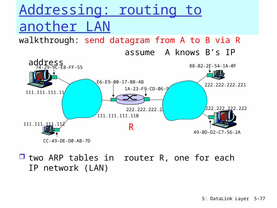
walkthrough: send datagram from A to B via R assume A knows B’s IP address
two ARP tables in router R, one for each IP network (LAN)

5: DataLink Layer 5-78
A creates IP datagram with source A, destination B A uses ARP to get R’s MAC address for 111.111.111.110 A creates link-layer frame with R's MAC address as dest,
frame contains A-to-B IP datagram A’s NIC sends frame R’s NIC receives frame R removes IP datagram from Ethernet frame, sees its
destined to B R uses ARP to get B’s MAC address R creates frame containing A-to-B IP datagram sends to B
R
1A-23-F9-CD-06-9B
222.222.222.220
111.111.111.110
E6-E9-00-17-BB-4B
CC-49-DE-D0-AB-7D
111.111.111.112
111.111.111.111
A74-29-9C-E8-FF-55
222.222.222.221
88-B2-2F-54-1A-0F
B222.222.222.222
49-BD-D2-C7-56-2A
This is a really importantexample – make sure youunderstand!
5: DataLink Layer 5-79
Link Layer
5.1 Introduction and services
Framing 5.2 Error detection
and correction 5.3Multiple access
protocols
LAN technology 5.5 Ethernet 5.6 Interconnection 5.4 Link-Layer
Addressing 5.7 PPP 5.9 A day in the life of
a web request(5.8 Link Virtualization:
ATM and MPLS)
5: DataLink Layer 5-80
Point to Point Data Link Control one sender, one receiver, one link: easier than
broadcast link: no Media Access Control no need for explicit MAC addressing e.g., dialup link, ISDN line
popular point-to-point DLC protocols: PPP (point-to-point protocol) HDLC: High level data link control
5: DataLink Layer 5-81
PPP Design Requirements [RFC 1557]
packet framing: encapsulation of network-layer datagram in data link frame
carry network layer data of any network layer protocol (not just IP)
bit transparency: no constraints on bit pattern in the data field
error detection (no correction) connection liveness: detect, signal link failure to
network layer network layer address negotiation: endpoint
can learn/configure each other’s network address

5: DataLink Layer 5-82
PPP non-requirements
no error correction/recovery no flow control “out of order” delivery OK
Error recovery, flow control, data re-ordering all relegated to higher layers!
5: DataLink Layer 5-83
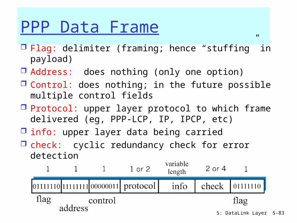
PPP Data Frame Flag: delimiter (framing; hence “stuffing” in
payload) Address: does nothing (only one option) Control: does nothing; in the future possible multiple
control fields Protocol: upper layer protocol to which frame
delivered (eg, PPP-LCP, IP, IPCP, etc) info: upper layer data being carried check: cyclic redundancy check for error detection
5: DataLink Layer 5-84
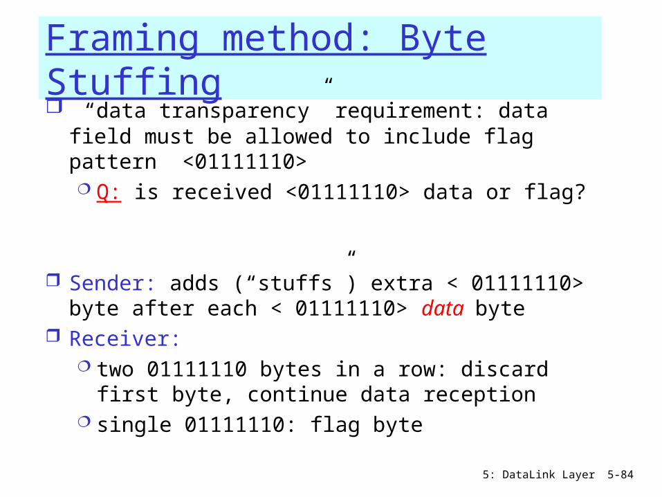
Framing method: Byte Stuffing “data transparency” requirement: data field
must be allowed to include flag pattern <01111110> Q: is received <01111110> data or flag?
Sender: adds (“stuffs”) extra < 01111110> byte after each < 01111110> data byte
Receiver: two 01111110 bytes in a row: discard first
byte, continue data reception single 01111110: flag byte
5: DataLink Layer 5-85
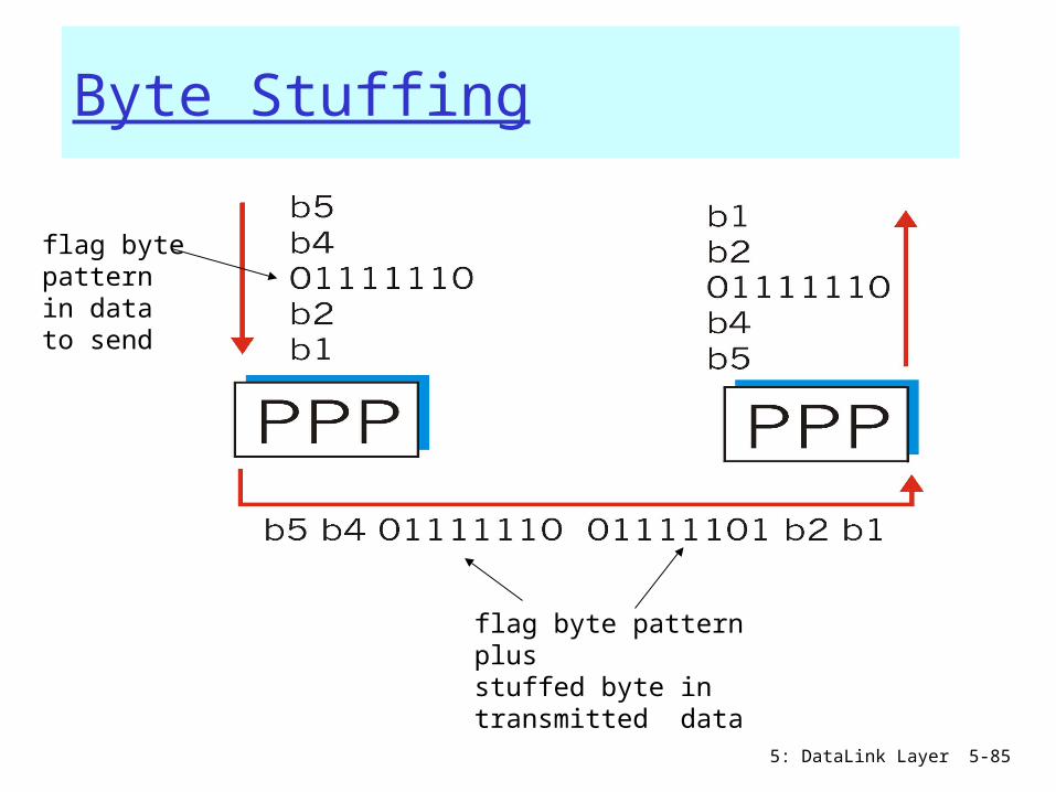
Byte Stuffing
flag bytepatternin datato send
flag byte pattern plusstuffed byte in transmitted data
5: DataLink Layer 5-86
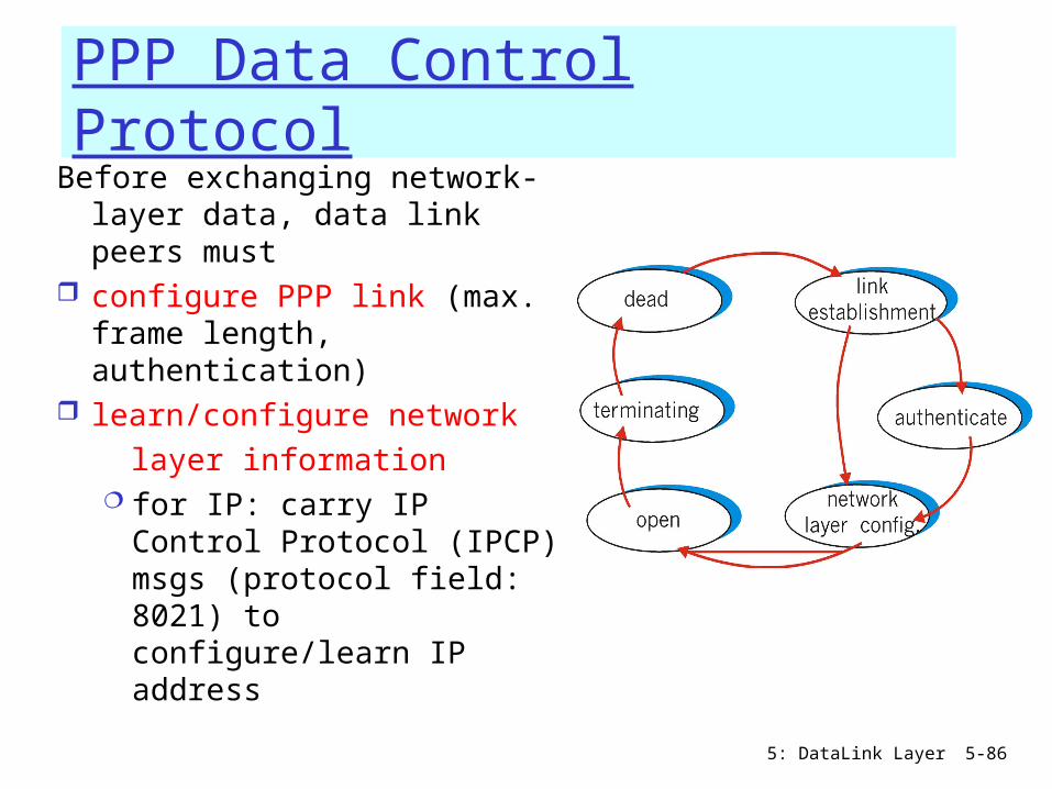
PPP Data Control ProtocolBefore exchanging network-
layer data, data link peers must
configure PPP link (max. frame length, authentication)
learn/configure network layer information
for IP: carry IP Control Protocol (IPCP) msgs (protocol field: 8021) to configure/learn IP address

5: DataLink Layer 5-87
Link Layer
5.1 Introduction and services
Framing 5.2 Error detection
and correction 5.3Multiple access
protocols
LAN technology 5.5 Ethernet 5.6 Interconnection 5.4 Link-Layer
Addressing 5.7 PPP 5.9 A day in the life of
a web request(5.8 Link Virtualization:
ATM and MPLS)
5: DataLink Layer 5-88
Synthesis: a day in the life of a web request
journey down protocol stack complete! application, transport, network, link
putting-it-all-together: synthesis! goal: identify, review, understand protocols
(at all layers) involved in seemingly simple scenario: requesting www page
scenario: student attaches laptop to campus network, requests/receives www.google.com

5: DataLink Layer 5-89
A day in the life: scenario
Comcast network 68.80.0.0/13
Google’s network 64.233.160.0/19 64.233.169.105
web server
DNS server
school network 68.80.2.0/24
browser
web page

5: DataLink Layer 5-90
A day in the life… connecting to the Internet
connecting laptop needs to get its own IP address, addr of first-hop router, addr of DNS server: use DHCP
router(runs DHCP)
DHCPUDP
IPEthPhy
DHCP
DHCP
DHCP
DHCP
DHCP
DHCPUDP
IPEthPhy
DHCP
DHCP
DHCP
DHCPDHCP
DHCP request encapsulated in UDP, encapsulated in IP, encapsulated in 802.1 Ethernet Ethernet frame broadcast (dest: FFFFFFFFFFFF) on LAN, received at router running DHCP server
Ethernet demux’ed to IP demux’ed, UDP demux’ed to DHCP
5: DataLink Layer 5-91
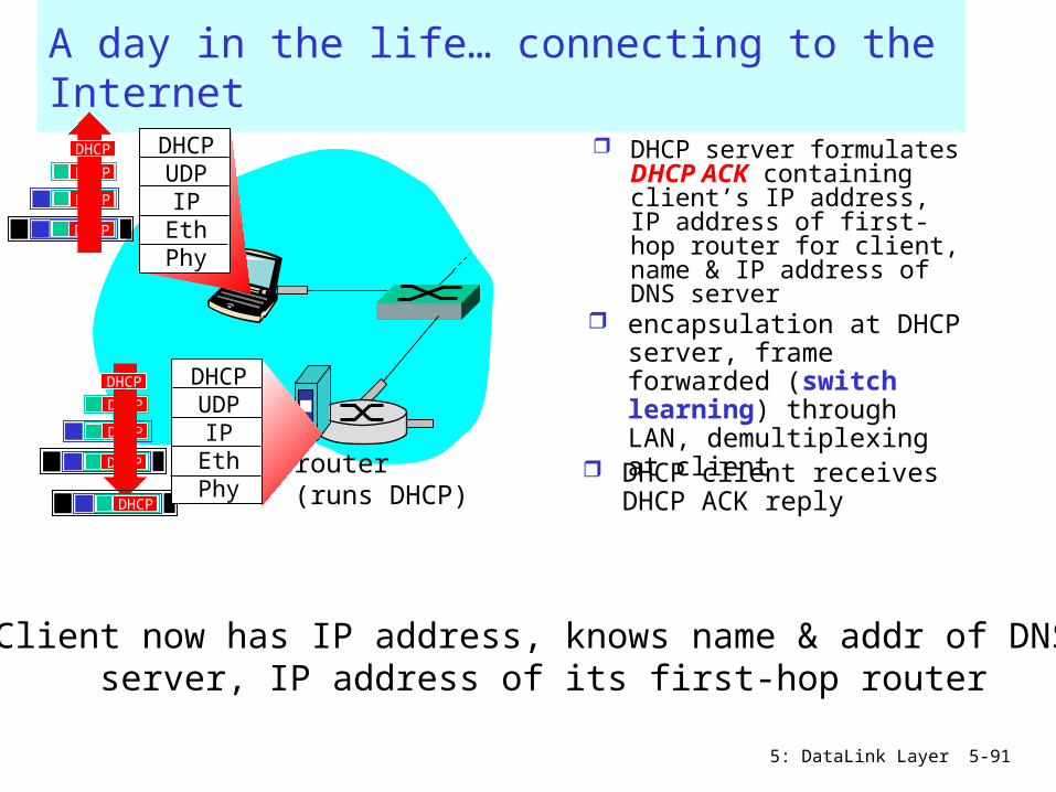
A day in the life… connecting to the Internet
DHCP server formulates DHCP ACK containing client’s IP address, IP address of first-hop router for client, name & IP address of DNS server
router(runs DHCP)
DHCPUDP
IPEthPhy
DHCP
DHCP
DHCP
DHCP
DHCPUDP
IPEthPhy
DHCP
DHCP
DHCP
DHCP
DHCP
encapsulation at DHCP server, frame forwarded (switch learning) through LAN, demultiplexing at client
Client now has IP address, knows name & addr of DNS server, IP address of its first-hop router
DHCP client receives DHCP ACK reply
5: DataLink Layer 5-92
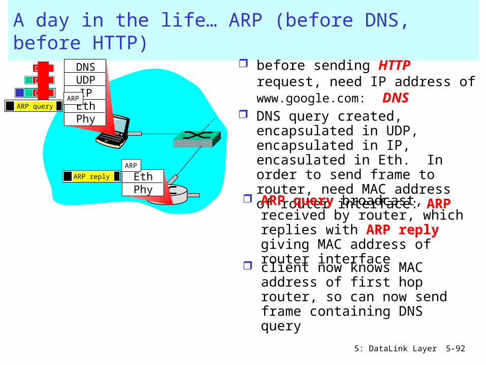
A day in the life… ARP (before DNS, before HTTP)
before sending HTTP request, need IP address of www.google.com: DNS
DNSUDP
IPEthPhy
DNS
DNS
DNS
DNS query created, encapsulated in UDP, encapsulated in IP, encasulated in Eth. In order to send frame to router, need MAC address of router interface: ARP
ARP query broadcast, received by router, which replies with ARP reply giving MAC address of router interface client now knows MAC address of first hop router, so can now send frame containing DNS query
ARP query
EthPhy
ARP
ARP
ARP reply

5: DataLink Layer 5-93
A day in the life… using DNS
DNSUDP
IPEthPhy
DNS
DNS
DNS
DNS
DNS
IP datagram containing DNS query forwarded via LAN switch from client to 1st hop router
IP datagram forwarded from campus network into comcast network, routed (tables created by RIP, OSPF and BGP routing protocols) to DNS server
demux’ed to DNS server DNS server replies to
client with IP address of www.google.com
Comcast network 68.80.0.0/13
DNS server
DNSUDP
IPEthPhy
DNS
DNS
DNS
DNS
5: DataLink Layer 5-94
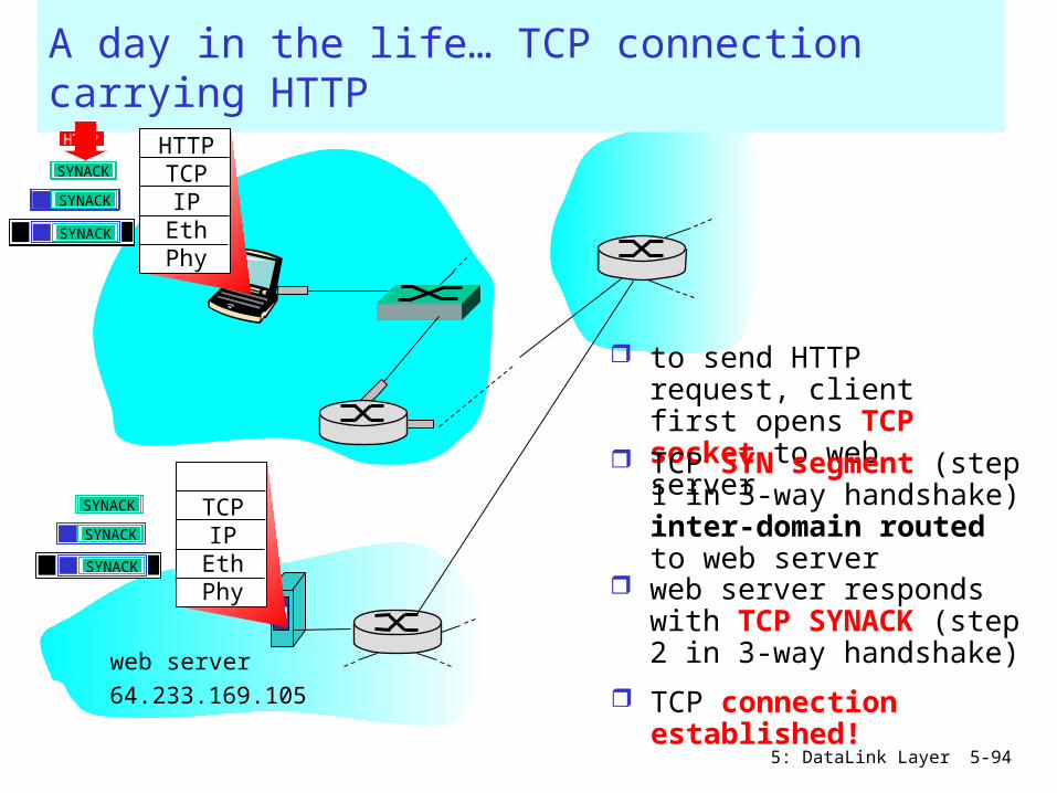
A day in the life… TCP connection carrying HTTP
HTTPTCPIP
EthPhy
HTTP
to send HTTP request, client first opens TCP socket to web server
TCP SYN segment (step 1 in 3-way handshake) inter-domain routed to web server
TCP connection established!
64.233.169.105
web server
SYN
SYN
SYN
SYN
TCPIP
EthPhy
SYN
SYN
SYN
SYNACK
SYNACK
SYNACK
SYNACK
SYNACK
SYNACK
SYNACK
web server responds with TCP SYNACK (step 2 in 3-way handshake)

5: DataLink Layer 5-95
A day in the life… HTTP request/reply
HTTPTCPIP
EthPhy
HTTP
HTTP request sent into TCP socket
IP datagram containing HTTP request routed to www.google.com
IP datgram containing HTTP reply routed back to client
64.233.169.105
web server
HTTPTCPIP
EthPhy
web server responds with HTTP reply (containing web page)
HTTP
HTTP
HTTPHTTP
HTTP
HTTP
HTTP
HTTP
HTTP
HTTP
HTTP
HTTP
HTTP
web page finally (!!!) displayed

5: DataLink Layer 5-96
Link Layer
5.1 Introduction and services
5.2 Error detection and correction
5.3Multiple access protocols
5.4 Link-Layer Addressing
5.5 Ethernet
5.6 Hubs and switches 5.7 PPP A day in the lifetime of
a web-request 5.8 Link Virtualization

5: DataLink Layer 5-97
Link Layer
5.1 Introduction and services
Framing 5.2 Error detection
and correction 5.3Multiple access
protocols
LAN technology 5.5 Ethernet 5.6 Interconnection 5.4 Link-Layer
Addressing 5.7 PPP 5.9 A day in the life of
a web request(5.8 Link Virtualization:
ATM and MPLS)

5: DataLink Layer 5-98
The Internet: virtualizing networks
1974: multiple unconnected nets ARPAnet data-over-cable networks packet satellite network (Aloha) packet radio network
… differing in: addressing conventions packet formats error recovery routing
ARPAnet satellite net"A Protocol for Packet Network Intercommunication", V. Cerf, R. Kahn, IEEE Transactions on Communications, May, 1974, pp. 637-648.
5: DataLink Layer 5-99
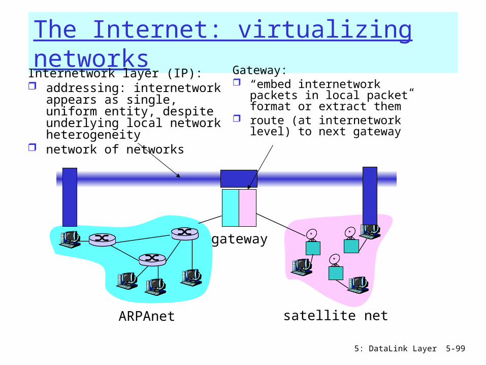
The Internet: virtualizing networks
ARPAnet satellite net
gateway
Internetwork layer (IP): addressing: internetwork
appears as single, uniform entity, despite underlying local network heterogeneity
network of networks
Gateway: “embed internetwork packets
in local packet format or extract them”
route (at internetwork level) to next gateway

5: DataLink Layer 5-100
Cerf & Kahn’s Internetwork ArchitectureWhat is virtualized? two layers of addressing: internetwork and local
network new layer (IP) makes everything homogeneous at
internetwork layer underlying local network technology
cable satellite 56K telephone modem today: ATM, MPLS
… “invisible” at internetwork layer. Looks like a link layer technology to IP!
5: DataLink Layer 5-101
ATM and MPLS
ATM, MPLS separate networks in their own right different service models, addressing, routing
from Internet viewed by Internet as logical link
connecting IP routers just like dialup link is really part of separate
network (telephone network) ATM, MPLS: of technical interest in their
own right

1: Introduction 102
On ATM: Asynchronous Transfer Mode nets
1980’s telco’s proposal for future networking Smart core, simple terminals
small (48 byte payload, 5 byte header) fixed length cells (like packets) fast switching (pipelined/cut-through) small size good for voice
virtual-circuit network: switches maintain state for each “call”
well-defined interface between “network” and “user” (think of telephone company):
several transport (Adaptation)-layer protocols, one per expected type of traffic
5: DataLink Layer 5-103
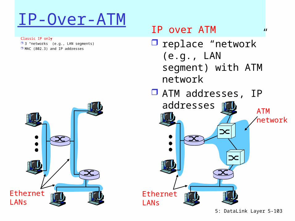
IP-Over-ATMClassic IP only 3 “networks” (e.g., LAN segments) MAC (802.3) and IP addresses
IP over ATM replace “network”
(e.g., LAN segment) with ATM network
ATM addresses, IP addresses
ATMnetwork
EthernetLANs
EthernetLANs

5: DataLink Layer 5-104
IP-Over-ATM
AALATMphyphy
Eth
IP
ATMphy
ATMphy
apptransport
IPAALATMphy
apptransport
IPEthphy

5: DataLink Layer 5-105
Datagram Journey in IP-over-ATM Network at Source Host:
IP layer maps between IP, ATM dest address (using ARP) passes datagram to AAL5 AAL5 encapsulates data, segments cells, passes to ATM
layer
ATM network: moves cell along VC to destination at Destination Host:
AAL5 reassembles cells into original datagram if CRC OK, datagram is passed to IP

5: DataLink Layer 5-106
IP-Over-ATM
Issues: IP datagrams into
ATM AAL5 PDUs from IP addresses
to ATM addresses just like IP
addresses to 802.3 MAC addresses!
ATMnetwork
EthernetLANs
5: DataLink Layer 5-107
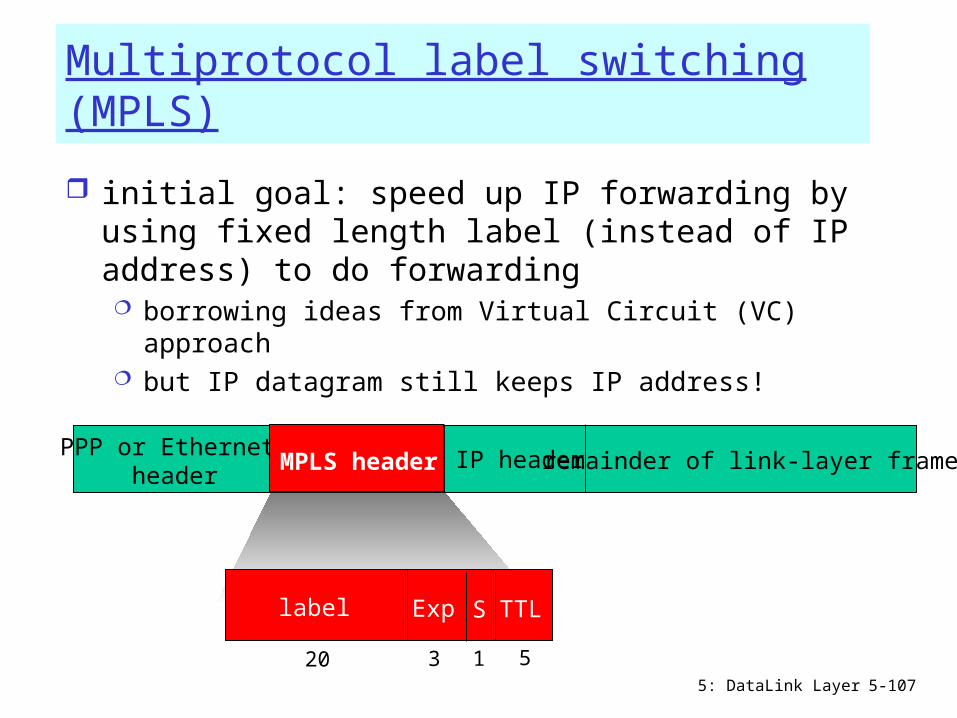
Multiprotocol label switching (MPLS)
initial goal: speed up IP forwarding by using fixed length label (instead of IP address) to do forwarding borrowing ideas from Virtual Circuit (VC) approach but IP datagram still keeps IP address!
PPP or Ethernet header
IP header remainder of link-layer frameMPLS header
label Exp S TTL
20 3 1 5

5: DataLink Layer 5-108
MPLS capable routers
a.k.a. label-switched router forwards packets to outgoing interface based
only on label value (don’t inspect IP address) MPLS forwarding table distinct from IP forwarding
tables signaling protocol needed to set up forwarding
RSVP-TE forwarding possible along paths that IP alone would
not allow (e.g., source-specific routing) !! use MPLS for traffic engineering
must co-exist with IP-only routers
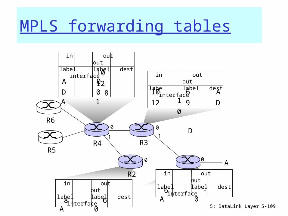
5: DataLink Layer 5-109
R1R2
D
R3R4R5
0
1
00
A
R6
in out outlabel label dest interface 6 - A 0
in out outlabel label dest interface10 6 A 1
12 9 D 0
in out outlabel label dest interface 10 A 0
12 D 0
1
in out outlabel label dest interface 8 6 A 0
0
8 A 1
MPLS forwarding tables

5: DataLink Layer 5-110
Chapter 5: Summary principles behind data link layer services:
error detection, correction sharing a broadcast channel: multiple access link layer addressing
instantiation and implementation of various link layer technologies Ethernet switched LANS PPP Link Virtualization: ATM and MPLS
Related Documents