17 Figure 5. The vertical dipole and its electromagnetic equivalent, the vertical monopole 5. ANTENNA TYPES Antennas can be classified in several ways. One way is the frequency band of operation. Others include physical structure and electrical/electromagnetic design. The antennas commonly used for LMR—both at base stations and mobile units—represent only a very small portion of all the antenna types. Most simple, nondirectional antennas are basic dipoles or monopoles. More complex, directional antennas consist of arrays of elements, such as dipoles, or use one active and several passive elements, as in the Yagi antenna. New antenna technologies are being developed that allow an antenna to rapidly change its pattern in response to changes in direction of arrival of the received signal. These antennas and the supporting technology are called adaptive or “smart” antennas and may be used for the higher- frequency LMR bands in the future. 5.1 Dipoles and Monopoles The vertical dipole—or its electromagnetic equivalent, the monopole—could be considered one of the best antennas for LMR applications. It is omnidirectional (in azimuth) and, if it is a half-wavelength long, has a gain of 1.64 (or G = 2.15 dBi) in the horizontal plane. A center-fed, vertical dipole is illustrated in figure 5(a). Although this is a simple antenna, it can be difficult to mount on a mast or vehicle. The ideal vertical monopole is illustrated in figure 5(b). It is half a dipole placed in half- space, with a perfectly conducting, infinite surface at the boundary. A monopole over an infinite ground plane is theoretically the same (identical gain, pattern, etc., in the half-space above the ground plane) as the dipole in free space. In practice, a ground plane cannot be infinite, but a ground plane with a radius approximately the same as the length of the active element, is an effective, practical solution. The flat surface of a vehicle’s trunk or roof can act as an adequate ground plane. Figure 6 shows typical monopole antennas for base-station and mobile applications.

Welcome message from author
This document is posted to help you gain knowledge. Please leave a comment to let me know what you think about it! Share it to your friends and learn new things together.
Transcript
17
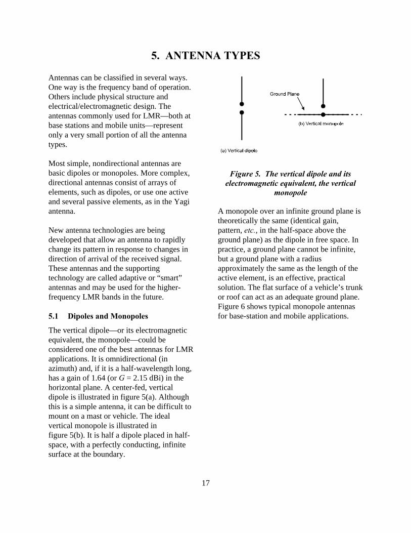
Figure 5. The vertical dipole and itselectromagnetic equivalent, the vertical
monopole
5. ANTENNA TYPES
Antennas can be classified in several ways.One way is the frequency band of operation.Others include physical structure andelectrical/electromagnetic design. Theantennas commonly used for LMR—both atbase stations and mobile units—representonly a very small portion of all the antennatypes.
Most simple, nondirectional antennas arebasic dipoles or monopoles. More complex,directional antennas consist of arrays ofelements, such as dipoles, or use one activeand several passive elements, as in the Yagiantenna.
New antenna technologies are beingdeveloped that allow an antenna to rapidlychange its pattern in response to changes indirection of arrival of the received signal.These antennas and the supportingtechnology are called adaptive or “smart”antennas and may be used for the higher-frequency LMR bands in the future.
5.1 Dipoles and Monopoles
The vertical dipole—or its electromagneticequivalent, the monopole—could beconsidered one of the best antennas for LMRapplications. It is omnidirectional (inazimuth) and, if it is a half-wavelength long,has a gain of 1.64 (or G = 2.15 dBi) in thehorizontal plane. A center-fed, verticaldipole is illustrated in figure 5(a). Althoughthis is a simple antenna, it can be difficult tomount on a mast or vehicle. The idealvertical monopole is illustrated infigure 5(b). It is half a dipole placed in half-space, with a perfectly conducting, infinitesurface at the boundary.
A monopole over an infinite ground plane istheoretically the same (identical gain,pattern, etc., in the half-space above theground plane) as the dipole in free space. Inpractice, a ground plane cannot be infinite,but a ground plane with a radiusapproximately the same as the length of theactive element, is an effective, practicalsolution. The flat surface of a vehicle’s trunkor roof can act as an adequate ground plane.Figure 6 shows typical monopole antennasfor base-station and mobile applications.
18
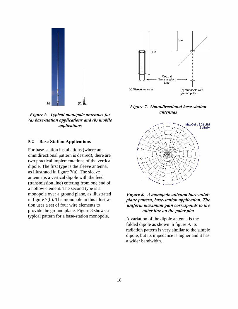
Figure 6. Typical monopole antennas for(a) base-station applications and (b) mobile
applications
Figure 7. Omnidirectional base-stationantennas
Figure 8. A monopole antenna horizontal-plane pattern, base-station application. Theuniform maximum gain corresponds to the
outer line on the polar plot
5.2 Base-Station Applications
For base-station installations (where anomnidirectional pattern is desired), there aretwo practical implementations of the verticaldipole. The first type is the sleeve antenna,as illustrated in figure 7(a). The sleeveantenna is a vertical dipole with the feed(transmission line) entering from one end ofa hollow element. The second type is amonopole over a ground plane, as illustratedin figure 7(b). The monopole in this illustra-tion uses a set of four wire elements toprovide the ground plane. Figure 8 shows atypical pattern for a base-station monopole.
A variation of the dipole antenna is thefolded dipole as shown in figure 9. Itsradiation pattern is very similar to the simpledipole, but its impedance is higher and it hasa wider bandwidth.
19
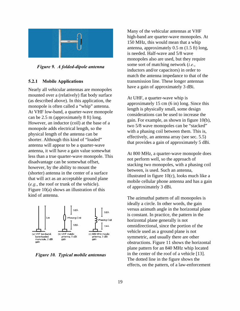
Figure 10. Typical mobile antennas
5.2.1 Mobile Applications
Nearly all vehicular antennas are monopolesmounted over a (relatively) flat body surface(as described above). In this application, themonopole is often called a “whip” antenna.At VHF low-band, a quarter-wave monopolecan be 2.5 m (approximately 8 ft) long.However, an inductor (coil) at the base of amonopole adds electrical length, so thephysical length of the antenna can beshorter. Although this kind of “loaded”antenna will appear to be a quarter-waveantenna, it will have a gain value somewhatless than a true quarter-wave monopole. Thisdisadvantage can be somewhat offset,however, by the ability to mount the(shorter) antenna in the center of a surfacethat will act as an acceptable ground plane(e.g., the roof or trunk of the vehicle).Figure 10(a) shows an illustration of thiskind of antenna.
Many of the vehicular antennas at VHFhigh-band are quarter-wave monopoles. At150 MHz, this would mean that a whipantenna, approximately 0.5 m (1.5 ft) long,is needed. Half-wave and 5/8 wavemonopoles also are used, but they requiresome sort of matching network (i.e.,inductors and/or capacitors) in order tomatch the antenna impedance to that of thetransmission line. These longer antennashave a gain of approximately 3 dBi.
At UHF, a quarter-wave whip isapproximately 15 cm (6 in) long. Since thislength is physically small, some designconsiderations can be used to increase thegain. For example, as shown in figure 10(b),two 5/8 wave monopoles can be “stacked”with a phasing coil between them. This is,effectively, an antenna array (see sec. 5.5)that provides a gain of approximately 5 dBi.
At 800 MHz, a quarter-wave monopole doesnot perform well, so the approach ofstacking two monopoles, with a phasing coilbetween, is used. Such an antenna,illustrated in figure 10(c), looks much like amobile cellular phone antenna and has a gainof approximately 3 dBi.
The azimuthal pattern of all monopoles isideally a circle. In other words, the gainversus azimuth angle in the horizontal planeis constant. In practice, the pattern in thehorizontal plane generally is notomnidirectional, since the portion of thevehicle used as a ground plane is notsymmetric, and usually there are otherobstructions. Figure 11 shows the horizontalplane pattern for an 840 MHz whip locatedin the center of the roof of a vehicle [13].The dotted line in the figure shows theeffects, on the pattern, of a law-enforcement
Figure 9. A folded-dipole antenna
20
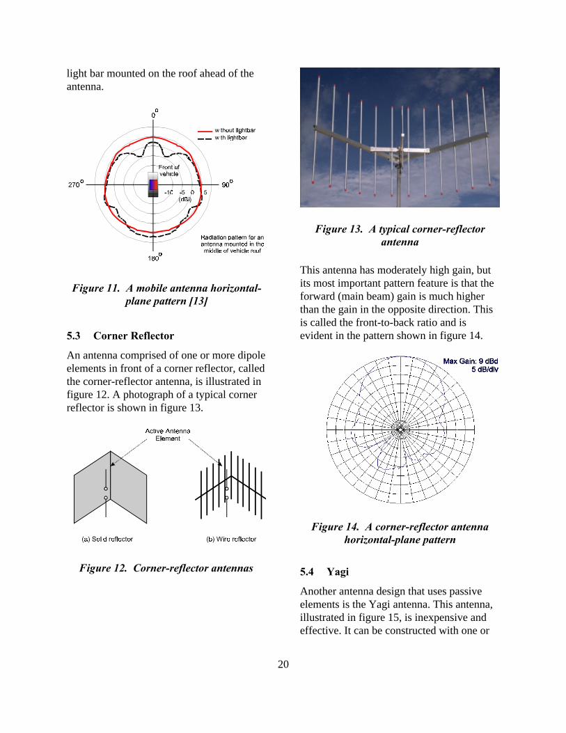
Figure 11. A mobile antenna horizontal-plane pattern [13]
Figure 12. Corner-reflector antennas
light bar mounted on the roof ahead of theantenna.
5.3 Corner Reflector
An antenna comprised of one or more dipoleelements in front of a corner reflector, calledthe corner-reflector antenna, is illustrated infigure 12. A photograph of a typical cornerreflector is shown in figure 13.
This antenna has moderately high gain, butits most important pattern feature is that theforward (main beam) gain is much higherthan the gain in the opposite direction. Thisis called the front-to-back ratio and isevident in the pattern shown in figure 14.
5.4 Yagi
Another antenna design that uses passiveelements is the Yagi antenna. This antenna,illustrated in figure 15, is inexpensive andeffective. It can be constructed with one or
Figure 13. A typical corner-reflectorantenna
Figure 14. A corner-reflector antennahorizontal-plane pattern
21
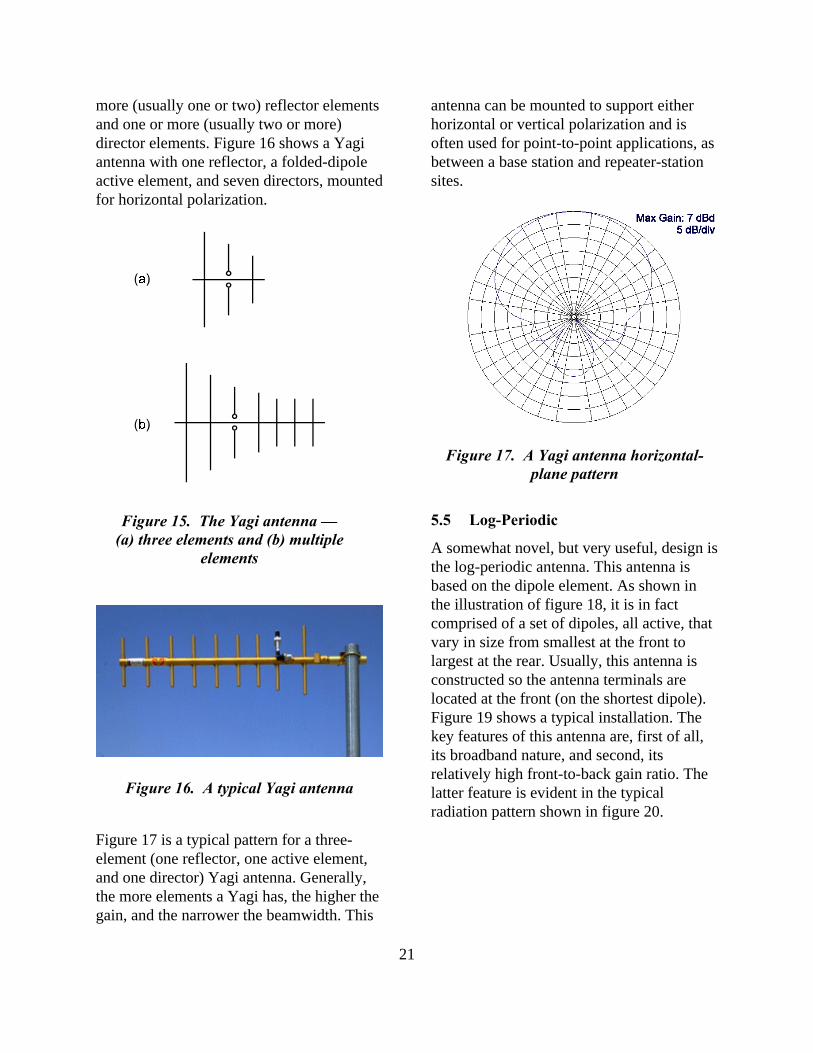
Figure 15. The Yagi antenna —(a) three elements and (b) multiple
elements
more (usually one or two) reflector elementsand one or more (usually two or more)director elements. Figure 16 shows a Yagiantenna with one reflector, a folded-dipoleactive element, and seven directors, mountedfor horizontal polarization.
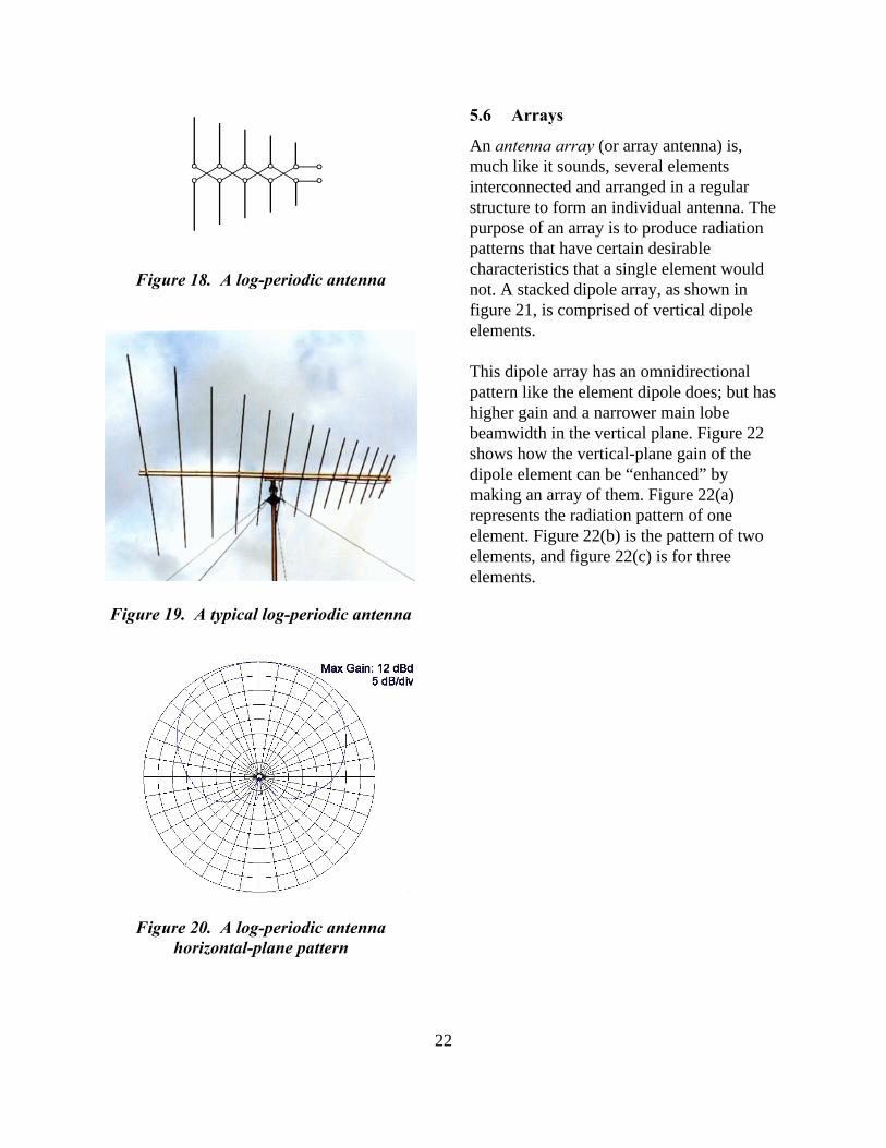
Figure 17 is a typical pattern for a three-element (one reflector, one active element,and one director) Yagi antenna. Generally,the more elements a Yagi has, the higher thegain, and the narrower the beamwidth. This
antenna can be mounted to support eitherhorizontal or vertical polarization and isoften used for point-to-point applications, asbetween a base station and repeater-stationsites.
5.5 Log-Periodic
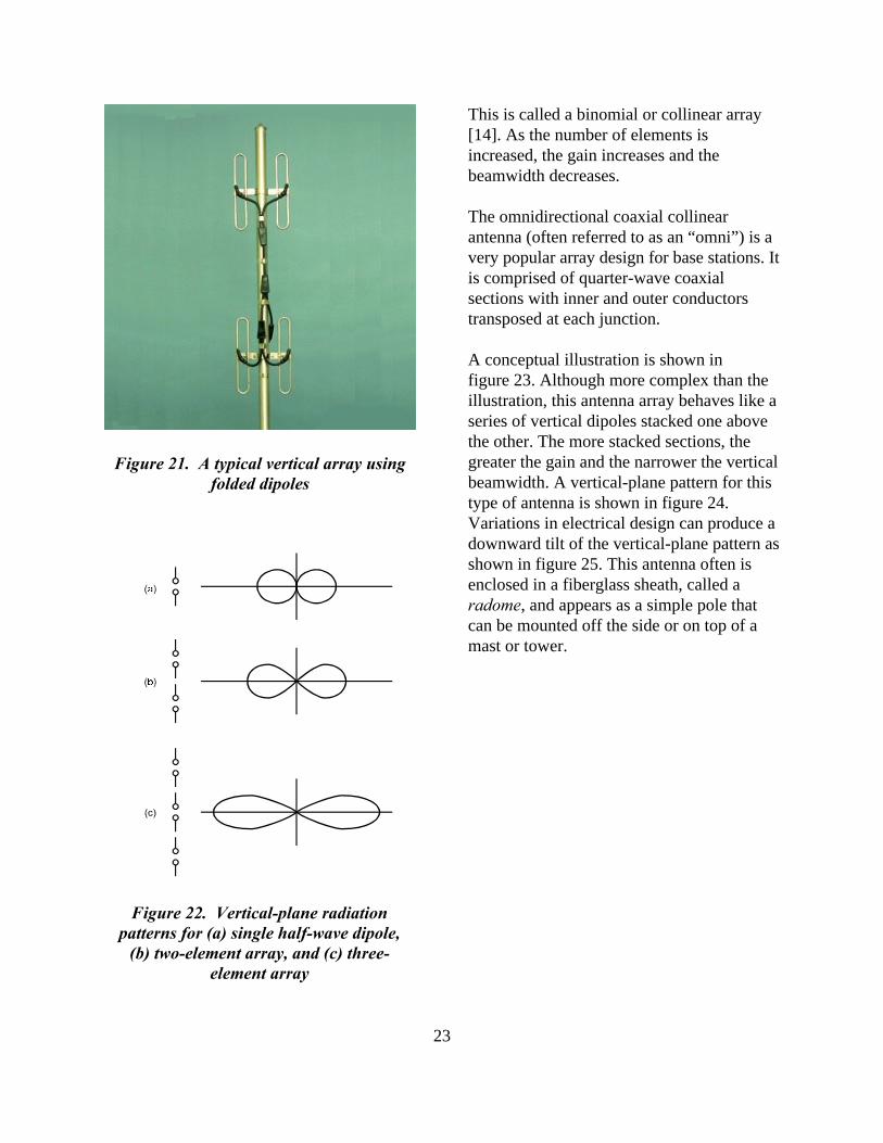
A somewhat novel, but very useful, design isthe log-periodic antenna. This antenna isbased on the dipole element. As shown inthe illustration of figure 18, it is in factcomprised of a set of dipoles, all active, thatvary in size from smallest at the front tolargest at the rear. Usually, this antenna isconstructed so the antenna terminals arelocated at the front (on the shortest dipole).Figure 19 shows a typical installation. Thekey features of this antenna are, first of all,its broadband nature, and second, itsrelatively high front-to-back gain ratio. Thelatter feature is evident in the typicalradiation pattern shown in figure 20.
Figure 16. A typical Yagi antenna
Figure 17. A Yagi antenna horizontal-plane pattern
22
Figure 18. A log-periodic antenna
Figure 19. A typical log-periodic antenna
Figure 20. A log-periodic antennahorizontal-plane pattern
5.6 Arrays
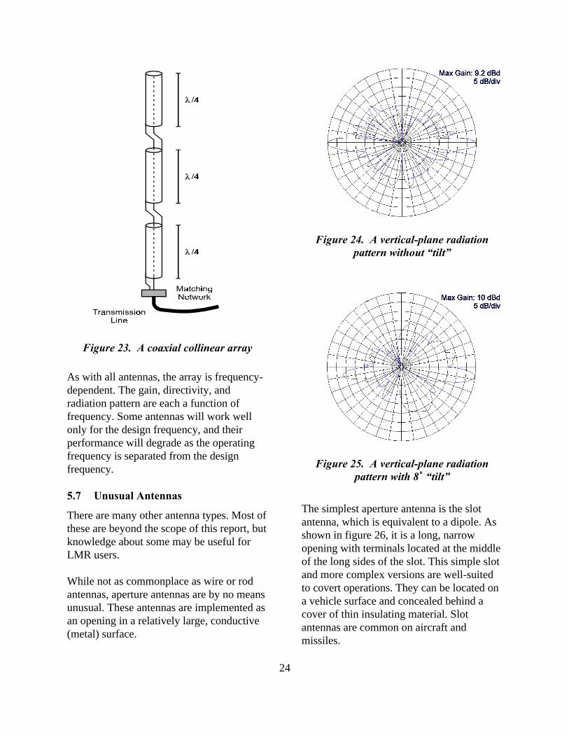
An antenna array (or array antenna) is,much like it sounds, several elementsinterconnected and arranged in a regularstructure to form an individual antenna. Thepurpose of an array is to produce radiationpatterns that have certain desirablecharacteristics that a single element wouldnot. A stacked dipole array, as shown infigure 21, is comprised of vertical dipoleelements.
This dipole array has an omnidirectionalpattern like the element dipole does; but hashigher gain and a narrower main lobebeamwidth in the vertical plane. Figure 22shows how the vertical-plane gain of thedipole element can be “enhanced” bymaking an array of them. Figure 22(a)represents the radiation pattern of oneelement. Figure 22(b) is the pattern of twoelements, and figure 22(c) is for threeelements.
23
Figure 21. A typical vertical array usingfolded dipoles
Figure 22. Vertical-plane radiationpatterns for (a) single half-wave dipole,
(b) two-element array, and (c) three-element array
This is called a binomial or collinear array[14]. As the number of elements isincreased, the gain increases and thebeamwidth decreases.
The omnidirectional coaxial collinearantenna (often referred to as an “omni”) is avery popular array design for base stations. Itis comprised of quarter-wave coaxialsections with inner and outer conductorstransposed at each junction.
A conceptual illustration is shown infigure 23. Although more complex than theillustration, this antenna array behaves like aseries of vertical dipoles stacked one abovethe other. The more stacked sections, thegreater the gain and the narrower the verticalbeamwidth. A vertical-plane pattern for thistype of antenna is shown in figure 24.Variations in electrical design can produce adownward tilt of the vertical-plane pattern asshown in figure 25. This antenna often isenclosed in a fiberglass sheath, called aradome, and appears as a simple pole thatcan be mounted off the side or on top of amast or tower.
24
Figure 23. A coaxial collinear array
Figure 25. A vertical-plane radiationpattern with 8// “tilt”
As with all antennas, the array is frequency-dependent. The gain, directivity, andradiation pattern are each a function offrequency. Some antennas will work wellonly for the design frequency, and theirperformance will degrade as the operatingfrequency is separated from the designfrequency.
5.7 Unusual Antennas
There are many other antenna types. Most ofthese are beyond the scope of this report, butknowledge about some may be useful forLMR users.
While not as commonplace as wire or rodantennas, aperture antennas are by no meansunusual. These antennas are implemented asan opening in a relatively large, conductive(metal) surface.
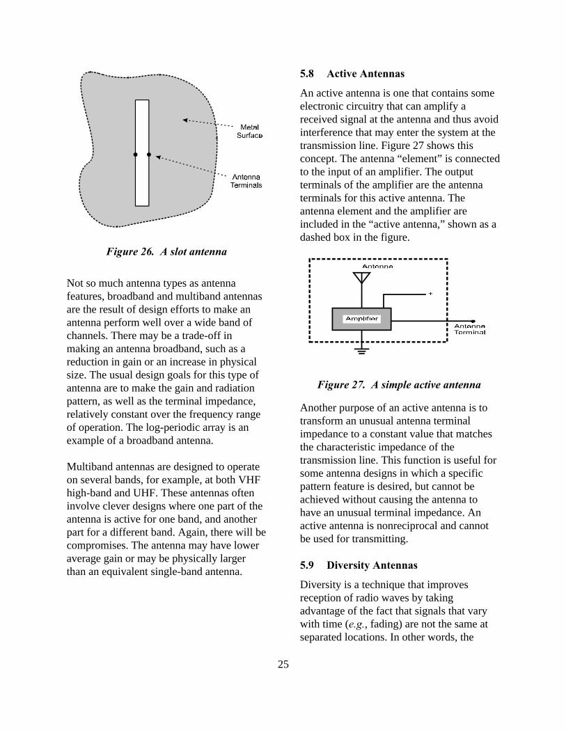
The simplest aperture antenna is the slotantenna, which is equivalent to a dipole. Asshown in figure 26, it is a long, narrowopening with terminals located at the middleof the long sides of the slot. This simple slotand more complex versions are well-suitedto covert operations. They can be located ona vehicle surface and concealed behind acover of thin insulating material. Slotantennas are common on aircraft andmissiles.
Figure 24. A vertical-plane radiationpattern without “tilt”
25
Figure 26. A slot antenna
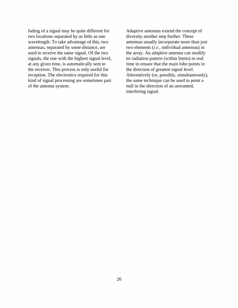
Figure 27. A simple active antenna
Not so much antenna types as antennafeatures, broadband and multiband antennasare the result of design efforts to make anantenna perform well over a wide band ofchannels. There may be a trade-off inmaking an antenna broadband, such as areduction in gain or an increase in physicalsize. The usual design goals for this type ofantenna are to make the gain and radiationpattern, as well as the terminal impedance,relatively constant over the frequency rangeof operation. The log-periodic array is anexample of a broadband antenna.
Multiband antennas are designed to operateon several bands, for example, at both VHFhigh-band and UHF. These antennas ofteninvolve clever designs where one part of theantenna is active for one band, and anotherpart for a different band. Again, there will becompromises. The antenna may have loweraverage gain or may be physically largerthan an equivalent single-band antenna.
5.8 Active Antennas
An active antenna is one that contains someelectronic circuitry that can amplify areceived signal at the antenna and thus avoidinterference that may enter the system at thetransmission line. Figure 27 shows thisconcept. The antenna “element” is connectedto the input of an amplifier. The outputterminals of the amplifier are the antennaterminals for this active antenna. Theantenna element and the amplifier areincluded in the “active antenna,” shown as adashed box in the figure.
Another purpose of an active antenna is totransform an unusual antenna terminalimpedance to a constant value that matchesthe characteristic impedance of thetransmission line. This function is useful forsome antenna designs in which a specificpattern feature is desired, but cannot beachieved without causing the antenna tohave an unusual terminal impedance. Anactive antenna is nonreciprocal and cannotbe used for transmitting.
5.9 Diversity Antennas
Diversity is a technique that improvesreception of radio waves by takingadvantage of the fact that signals that varywith time (e.g., fading) are not the same atseparated locations. In other words, the
26
fading of a signal may be quite different fortwo locations separated by as little as onewavelength. To take advantage of this, twoantennas, separated by some distance, areused to receive the same signal. Of the twosignals, the one with the highest signal level,at any given time, is automatically sent tothe receiver. This process is only useful forreception. The electronics required for thiskind of signal processing are sometimes partof the antenna system.
Adaptive antennas extend the concept ofdiversity another step further. Theseantennas usually incorporate more than justtwo elements (i.e., individual antennas) inthe array. An adaptive antenna can modifyits radiation pattern (within limits) in realtime to ensure that the main lobe points inthe direction of greatest signal level.Alternatively (or, possibly, simultaneously),the same technique can be used to point anull in the direction of an unwanted,interfering signal.
Related Documents