4th Year Systems Design 4th Year Systems Design Workshop Workshop ROUTE System ROUTE System Workshop Group #24 Workshop Group #24 Danny Ho Danny Ho Macy Lui Macy Lui Gegi Thomas Gegi Thomas Supervisors: Supervisors: Prof. Doug Dudycha Prof. Doug Dudycha (GEOG) (GEOG) Prof. Eric Kubica (SY Prof. Eric Kubica (SY DE) DE) March 21, 2002

4th Year Systems Design Workshop ROUTE System Workshop Group #24 Danny Ho Macy Lui Gegi Thomas Supervisors: Prof. Doug Dudycha (GEOG) Prof. Eric Kubica.
Dec 18, 2015
Welcome message from author
This document is posted to help you gain knowledge. Please leave a comment to let me know what you think about it! Share it to your friends and learn new things together.
Transcript
4th Year Systems Design 4th Year Systems Design WorkshopWorkshop
ROUTE SystemROUTE System
Workshop Group #24Workshop Group #24Danny HoDanny HoMacy LuiMacy LuiGegi ThomasGegi Thomas
Supervisors:Supervisors:Prof. Doug Dudycha Prof. Doug Dudycha (GEOG)(GEOG)Prof. Eric Kubica (SY DE)Prof. Eric Kubica (SY DE)
March 21, 2002

OverviewOverview
1.1. IntroductionIntroduction
2.2. The ROUTE SystemThe ROUTE System
3.3. DemonstrationDemonstration
4.4. Design ArchitectureDesign Architecture- Client- Client
- Server- Server
5.5. ConclusionConclusion
6.6. Future ConsiderationsFuture Considerations

IntroductionIntroduction
• Traffic congestion is a Traffic congestion is a common societal problemcommon societal problem
• Current navigation software Current navigation software assumes static traffic flowassumes static traffic flow
• Absence of link between Absence of link between road conditions and path road conditions and path calculationcalculation
Introduction
The ROUTE System
Demonstration
Design Architecture
- Client
- Server
Conclusion
Future
Considerations

Problem StatementProblem Statement
Provide motorists with efficient, Provide motorists with efficient, accurate directions from origin accurate directions from origin to destination using user-to destination using user-position and coincident traffic position and coincident traffic delay information, to reduce delay information, to reduce traffic congestion, and its traffic congestion, and its subsequent costs, in urban subsequent costs, in urban areas.areas.
Introduction
The ROUTE System
Demonstration
Design Architecture
- Client
- Server
Conclusion
Future
Considerations

Our SolutionOur Solution
• ROUTEROUTE System = System = RRoute oute OOptimization ptimization UUsing sing TTraffic raffic EEvents vents SystemSystem
• Input: Input: – Live traffic data (road speeds Live traffic data (road speeds
collected via road sensors)collected via road sensors)– Desired destination (entered by user Desired destination (entered by user
using front-end interface)using front-end interface)– Current geographical location of Current geographical location of
vehicle (detected using GPS device)vehicle (detected using GPS device)
Introduction
The ROUTE System
Demonstration
Design Architecture
- Client
- Server
Conclusion
Future
Considerations

Our Solution – cont’dOur Solution – cont’d
• Output:Output:– Optimized path of travel (displayed Optimized path of travel (displayed
in GUI on a portable device)in GUI on a portable device)
• Scope:Scope:– Street network of Street network of
Kitchener/WaterlooKitchener/Waterloo
Introduction
The ROUTE System
Demonstration
Design Architecture
- Client
- Server
Conclusion
Future
Considerations

Overall Design GoalOverall Design Goal
Introduction
The ROUTE System
Demonstration
Design Architecture
- Client
- Server
Conclusion
Future
Considerations
From Concept to Design…

Design ApproachDesign Approach
• Evolutionary PrototypingEvolutionary Prototyping– Client feature developmentClient feature development
• Rapid PrototypingRapid Prototyping– Client interface developmentClient interface development
• Use of Use of ChunksChunks– Location acquisitionLocation acquisition– Client User Interface ModuleClient User Interface Module– Route optimization ModuleRoute optimization Module– Traffic network DatabaseTraffic network Database
Introduction
The ROUTE System
Demonstration
Design Architecture
- Client
- Server
Conclusion
Future
Considerations

DemonstrationDemonstration
• Path optimization with Path optimization with current location and current location and destinationdestination
• Update and re-optimize Update and re-optimize when traffic condition when traffic condition changeschanges
Introduction
The ROUTE System
Demonstration
Design Architecture
- Client
- Server
Conclusion
Future
Considerations

Design ArchitectureDesign Architecture
• Separation of Computing ResponsibilitiesSeparation of Computing Responsibilities
– Client:Client: •User Entry InterfaceUser Entry Interface
•Location IdentificationLocation Identification
•Path RenderingPath Rendering– Server:Server:
•Path OptimizationPath Optimization
•Traffic Data HandlingTraffic Data Handling
Client / Server ParadigmClient / Server Paradigm
Introduction
The ROUTE System
Demonstration
Design Architecture
- Client
- Server
Conclusion
Future
Considerations

Design ArchitectureDesign ArchitectureClient-Side ArchitectureClient-Side Architecture
Introduction
The ROUTE System
Demonstration
Design Architecture
- Client
- Server
Conclusion
Future
Considerations

Design ArchitectureDesign Architecture
• Location ProcessorLocation Processor
• Route HandlerRoute Handler
• ESRI MapObjects map controlESRI MapObjects map control
• Street network data fileStreet network data fileIntroduction
Business Objectives
Demonstration
Design Architecture
Future
Enhancements
Conclusion
Client – System Inputs/OutputsClient – System Inputs/Outputs

Design ArchitectureDesign Architecture
• InputsInputs– GPS coordinate from GPS deviceGPS coordinate from GPS device– Street network data file (shape file)Street network data file (shape file)– Edge list of optimized route from Edge list of optimized route from
ServerServer
• OutputsOutputs– Parameters for optimizationParameters for optimization– Onscreen map output to userOnscreen map output to user
Client – System Inputs/OutputsClient – System Inputs/Outputs
Introduction
The ROUTE System
Demonstration
Design Architecture
- Client
- Server
Conclusion
Future
Considerations

Design ArchitectureDesign ArchitectureServer ArchitectureServer Architecture
Introduction
The ROUTE System
Demonstration
Design Architecture
- Client
- Server
Conclusion
Future
Considerations

Design ArchitectureDesign Architecture
• Requirements for optimizationRequirements for optimization
• Decision: Dijkstra’s algorithmDecision: Dijkstra’s algorithm
• Advantages/DisadvantagesAdvantages/Disadvantages
Server Side - Route OptimizationServer Side - Route Optimization
Introduction
The ROUTE System
Demonstration
Design Architecture
- Client
- Server
Conclusion
Future
Considerations
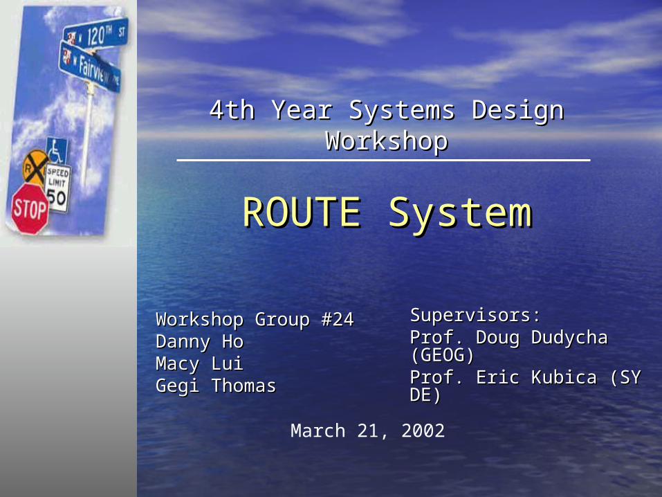
Design ArchitectureDesign ArchitectureData Investigation & RepresentationData Investigation & Representation
NODE_ ARC1_ ARC2_ AZIMUTH ANGLE ARC1_ID ARC2_ID1 1628 1627 25.499 -85.819 1628 16271 1628 918 25.499 91.704 1628 9181 1627 1628 291.318 85.819 1627 16281 1627 918 291.318 -2.477 1627 9181 918 1628 113.795 -91.704 918 16281 918 1627 113.795 2.477 918 16272 918 917 202.084 86.713 918 9172 918 649 202.084 -81.308 918 6492 917 918 295.372 -86.713 917 9182 917 649 295.372 11.979 917 6492 649 918 103.392 81.308 649 9182 649 917 103.392 -11.979 649 9173 1494 917 51.201 94.479 1494 9173 1494 916 51.201 -94.616 1494 9163 917 1494 136.722 -94.479 917 14943 917 916 136.722 -9.095 917 916
TNODE_ LENGTH KWRDS_ ST_NAME TIME_IMP10 390.830 1 WEBER ST N 31.2668 208.501 2 KING ST N 16.680
994 61.251 3 REG RD 70 TO HWY 7/8 E_BND 4.009990 239.345 4 REG RD 70 TO HWY 7/8 E_BND 15.666994 105.104 5 REG RD 70 TO HWY 7/8 E_BND 6.880315 254.607 6 MARGARET AVE 16.665290 78.559 7 MARGARET AVE 5.142281 171.243 8 WELLINGTON ST N 13.699496 162.913 9 VICTORIA ST N 13.033496 149.292 10 WATER ST N 11.943493 18.505 11 VICTORIA ST N 1.480494 17.614 12 VICTORIA ST N 1.409910 246.562 13 STRASBURG RD 16.139936 199.060 14 BLOCK LINE RD 13.029
Introduction
The ROUTE System
Demonstration
Design Architecture
- Client
- Server
Conclusion
Future
Considerations

ConclusionsConclusions
• Successful implementation of Successful implementation of core ROUTE System componentscore ROUTE System components
• A robust, portable, client-server A robust, portable, client-server solution for traffic route mappingsolution for traffic route mapping
• Positive societal implications:Positive societal implications:– Improved emergency vehicle Improved emergency vehicle
responseresponse– Increased enjoyment of drivingIncreased enjoyment of driving– Cleaner environmentCleaner environment
Introduction
The ROUTE System
Demonstration
Design Architecture
- Client
- Server
Conclusion
Future
Considerations

Future ConsiderationsFuture Considerations
• Public policy to fully adopt traffic Public policy to fully adopt traffic sensors in citiessensors in cities
• Standardized data collection and Standardized data collection and map formats amongst citiesmap formats amongst cities
• Package this to popular devicesPackage this to popular devices• Compatibility with any GPS and Compatibility with any GPS and
wireless deviceswireless devices• Improved network performance Improved network performance
& scalability& scalability
Introduction
The ROUTE System
Demonstration
Design Architecture
- Client
- Server
Conclusion
Future
Considerations

Questions?Questions?
• Thank you for attending our Thank you for attending our presentation.presentation.
• Supervisor Acknowledgment:Supervisor Acknowledgment:– Prof. Doug Dudycha (GEOG)Prof. Doug Dudycha (GEOG)– Prof. Eric Kubica (SY DE)Prof. Eric Kubica (SY DE)
• Other Other AcknowledgmentsAcknowledgments– Ian Mackenzie (GEOG)Ian Mackenzie (GEOG)– Steve Kemp (City of Toronto)Steve Kemp (City of Toronto)– Prof. Hallinga (Civil Engineering)Prof. Hallinga (Civil Engineering)

Design ArchitectureDesign Architecture
• Location ProcessorLocation Processor– Track route historyTrack route history– Perform bearing calculationsPerform bearing calculations– Perform position tracingPerform position tracing– Determine source node for path Determine source node for path
findingfinding– Determine destination node for path Determine destination node for path
findingfinding
Client – ComponentsClient – Components

Design ArchitectureDesign Architecture
• Route HandlerRoute Handler– Process routes returned by serverProcess routes returned by server– Detect deviations from best pathDetect deviations from best path
Client – ComponentsClient – Components

Design ArchitectureDesign Architecture
• Street network data fileStreet network data file– Shapefile format (industry standard)Shapefile format (industry standard)– Contains geographical vector dataContains geographical vector data– Contains street info (names, etc.)Contains street info (names, etc.)– Commonly used dataset for any Commonly used dataset for any
geographical system applicationsgeographical system applications
Client - ComponentsClient - Components

Design ArchitectureDesign Architecture
• ESRIESRI©© MapObjects map control MapObjects map control– Reads Shapefile of street networkReads Shapefile of street network– Used to display all map featuresUsed to display all map features
Client - ComponentsClient - Components
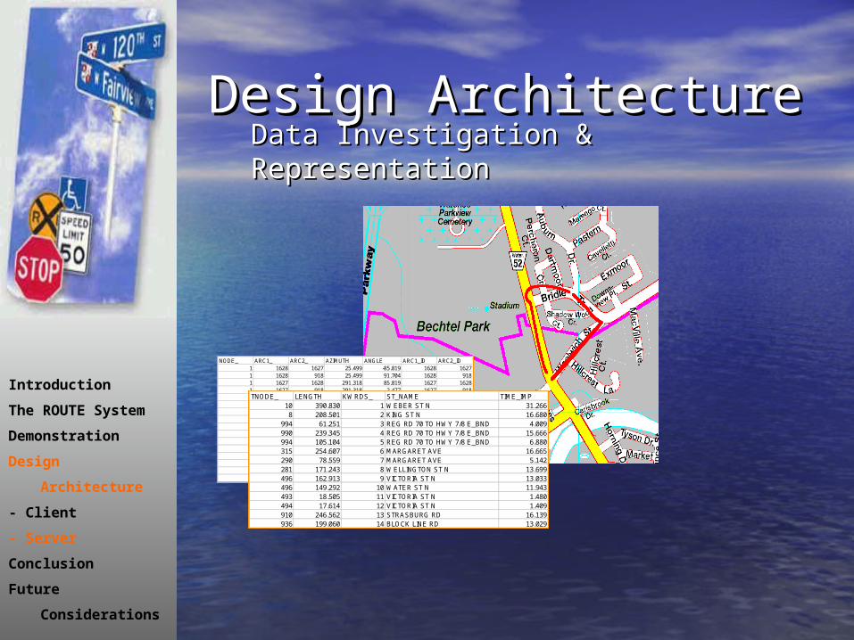
SCOOTSCOOT
• Demand ResponsiveDemand Responsive
• Data Transmission in real-Data Transmission in real-timetime
• Employed at intersectionsEmployed at intersections
• 279 intersections in Toronto 279 intersections in Toronto systemsystem
Urban Traffic Control SystemUrban Traffic Control System

SCOOTSCOOTUrban Traffic Control SystemUrban Traffic Control System

Design ArchitectureDesign ArchitectureServer ArchitectureServer Architecture

IBM WebSphereIBM WebSphere
• Industrial Strength ServerIndustrial Strength Server
65% of the Fortune 500 companies 65% of the Fortune 500 companies
80% of the top US healthcare companies80% of the top US healthcare companies
75% of commercial banks worldwide75% of commercial banks worldwide
90% of the top commercial banks in the US 90% of the top commercial banks in the US
67% of the world's largest banks use 67% of the world's largest banks use
IBM messaging servers IBM messaging servers
15 of the top Wall Street brokerage firms15 of the top Wall Street brokerage firms
7 of the 8 largest US telecommunications 7 of the 8 largest US telecommunications companies companies
[Source : http://www-3.ibm.com/software/webservers/appserv/]

ESRIESRI
• Geographical Product LineGeographical Product Line
• ESRI MapObjects, ArcView, ESRI MapObjects, ArcView, ArcIMSArcIMS
• Consideration Factors:Consideration Factors:– FinancialFinancial– Ease of Implementation / TimeEase of Implementation / Time– Feasibility of ImplementationFeasibility of Implementation
Design MethodologyDesign Methodology
Design Trade-offs & ConsiderationsDesign Trade-offs & Considerations
- Server Implementation Logic- Server Implementation Logic
- 3- 3rdrd Party vs. Proprietary Party vs. Proprietary
- Server Connectivity- Server Connectivity
- Protocols (HTTP vs. SMS)- Protocols (HTTP vs. SMS)
- Computing Design- Computing Design
- Client vs. Server-centric- Client vs. Server-centric

The Impedance IssueThe Impedance Issue
• II - Impedance is measured in time - Impedance is measured in time taken to travel an arc (sec)taken to travel an arc (sec)
• SS - Average speeds of each road are - Average speeds of each road are sensed (meters/sec)sensed (meters/sec)
• LL - The lengths of the arcs are known - The lengths of the arcs are known and static (m)and static (m)
Impedance, I = S x LImpedance, I = S x L
Potential optimizations include:Potential optimizations include:Fastest/shortest/consistent travel speedFastest/shortest/consistent travel speed

The TAXI SolutionThe TAXI Solution

MarketMarket Analysis Analysis
• Major coMajor contributorsntributors::– Digital map servicesDigital map services
•MapQuest.comMapQuest.com
– In-vehicle voice servicesIn-vehicle voice services•OnStarOnStar

ScreenshotsScreenshots

ScreenshotsScreenshots
Related Documents