www.ee.ntou.edu .tw Department of Electrical Engineering, National Taiwan Ocean University NuMicro GPIO 4/25/2015 Richard Kuo Assistant Professor

Welcome message from author
This document is posted to help you gain knowledge. Please leave a comment to let me know what you think about it! Share it to your friends and learn new things together.
Transcript

www.ee.ntou.edu.twDepartment of Electrical Engineering,
National Taiwan Ocean University
NuMicro GPIO
4/25/2015
Richard Kuo
Assistant Professor

Department of Electrical Engineering, National Taiwan Ocean University
www.ee.ntou.edu.tw
Outline
4.NuMicro_GPIO.pptGPIO Interface Introduction►Lab. LED control (smpl_GPIO_LED1, smpl_GPIO_RGBled)►Lab. Buzzer control (smpl_GPIO_Buzzer)►Lab. Sensor input (smpl_GPIO_PIR)►Lab. 7-segment Display (smpl_7seg)►Lab. Keypad scanning (smpl_Keypad)►Lab. Step Motor control (smpl_GPIO_StepMotor)►Lab. GPIO Interrupt (smpl_GPIO_IRQ)
►Homework : LED Cube 3x3x3►Homework: Electronic Safe

Department of Electrical Engineering, National Taiwan Ocean University
www.ee.ntou.edu.tw
Peripherals
To use GPIO to access the following components/modules
PIRIRBuzzerLEDs
Step MotorRelaysKeypad

Department of Electrical Engineering, National Taiwan Ocean University
www.ee.ntou.edu.tw
GPIO pins of NUC140 LQFP-100

Department of Electrical Engineering, National Taiwan Ocean University
www.ee.ntou.edu.tw
GPIO pins of Nano102 LQFP-64

Department of Electrical Engineering, National Taiwan Ocean University
www.ee.ntou.edu.tw
GPIO I/O Modes : Input
► Input only with high impedance
– Set GPIOx_PMD (PMDn[1:0]) to 00b the GPIOx port [n] pin is in Input mode
– and the I/O pin is in tri-state (high impedance) without output drive capability
GPIO_SetMode(PC, BIT12, GPIO_PMD_INPUT);

Department of Electrical Engineering, National Taiwan Ocean University
www.ee.ntou.edu.tw
GPIO I/O Modes - Output
► Push-Pull Output
GPIO_SetMode(PC, BIT12, GPIO_PMD_OUTPUT);

Department of Electrical Engineering, National Taiwan Ocean University
www.ee.ntou.edu.tw
GPIO I/O Modes – Open_Drain
► Open-Drain
GPIO_SetMode(PC, BIT12, GPIO_PMD_OPEN_DRAIN);

Department of Electrical Engineering, National Taiwan Ocean University
www.ee.ntou.edu.tw
GPIO I/O Modes
► Quasi bi-direction
GPIO_SetMode(PC, BIT12, GPIO_PMD_QUASI);

Department of Electrical Engineering, National Taiwan Ocean University
www.ee.ntou.edu.tw
StdDriver/GPIO_OutputInput
► GPIO set mode : GPIO_SetMode(PA, BIT12, GPIO_PMD_OUTPUT);
I/O groups : NUC140 = GPA, GPB, GPC, GPD, GPENANO102 = PA, PB, PC, PD, PE, PF
port no = BIT0~15 I/O modes
GPIO_PMD_INPUT : input only modeGPIO_PMD_OUTPUT : push-pull output modeGPIO_PMD_OPEN_DRAIN : open-drain output modeGPIO_PMD_QUASI : quai bi-direction mode
► Output value : PA12 = 0; ► Read Input : if (PA12 !=0) { }

Department of Electrical Engineering, National Taiwan Ocean University
www.ee.ntou.edu.tw
LED schematic (Nu-LB-NUC140)

Department of Electrical Engineering, National Taiwan Ocean University
www.ee.ntou.edu.tw
LED
PC12
GPIO_SetMode(PC, BIT12, GPIO_PMD_OUTPUT);
Each IO pad drive/sink ~25mAEntire Chip drive/sink ~200mA

Department of Electrical Engineering, National Taiwan Ocean University
www.ee.ntou.edu.tw
smpl_GPIO_LED1
int main(void)
{
SYS_Init();
GPIO_SetMode(PC, BIT12, GPIO_PMD_OUTPUT);
while(1) {
PC12 =0; // turn on LED
CLK_SysTickDelay(100000); // Delay
PC12 =1; // turn off LED
CLK_SysTickDelay(100000); // Delay
}
}
Output Mode
Initialize Clocks & Pins

Department of Electrical Engineering, National Taiwan Ocean University
www.ee.ntou.edu.tw
PIR (Passive InfraRed) sensor

Department of Electrical Engineering, National Taiwan Ocean University
www.ee.ntou.edu.tw
PIR (Passive InfraRed) schemiatc

Department of Electrical Engineering, National Taiwan Ocean University
www.ee.ntou.edu.tw
PIR (Passive InfraRed) application circuit
Application Circuit
5~9V Battery

Department of Electrical Engineering, National Taiwan Ocean University
www.ee.ntou.edu.tw
smpl_GPIO_PIR
display Detection message
Passive Infrared Detectordetecting human body

Department of Electrical Engineering, National Taiwan Ocean University
www.ee.ntou.edu.tw
smpl_GPIO_PIR
int main(void)
{
SYS_Init();
GPIO_SetMode(PA, BIT0, GPIO_PMD_INPUT);
while(1) {
if (PA0==1) printf("PIR detected!\n");
else printf("PIR no detection!\n");
}
}
Input Mode

Department of Electrical Engineering, National Taiwan Ocean University
www.ee.ntou.edu.tw
Reflective Optical Sensor : TCRT5000
PictureApplication Circuit
Top ViewIR Diode keep emitting Infrared lightIR Transistor receive the reflective Infrared light
220
PA0
Vcc
Gnd
TCRT5000
R1R2
10K

Department of Electrical Engineering, National Taiwan Ocean University
www.ee.ntou.edu.tw
Buzzer schematic (Nu-LB-NUC140)
0 ohm
R1 is shorted

Department of Electrical Engineering, National Taiwan Ocean University
www.ee.ntou.edu.tw
smpl_GPIO_Buzzer
void Init_Buzzer(void)
{
GPIO_SetMode(PB, BIT11, GPIO_PMD_OUTPUT);
PB11=1; // turn off Buzzer
}
void Buzz(int number)
{
int i;
for (i=0; i<number; i++) {
PB11 =0; // turn on Buzzer
CLK_SysTickDelay(100000); // Delay
PB11 =1; // turn off Buzzer
CLK_SysTickDelay(100000); // Delay
}
}

Department of Electrical Engineering, National Taiwan Ocean University
www.ee.ntou.edu.tw
7-segment display

Department of Electrical Engineering, National Taiwan Ocean University
www.ee.ntou.edu.tw
7seg. LED schematics (Nu-LB-NUC140)
Drive Low will turn on 7-seg. LED

Department of Electrical Engineering, National Taiwan Ocean University
www.ee.ntou.edu.tw
Seven_Segment.c
#include <stdio.h>
#include "NUC100Series.h"
#include "GPIO.h"
#include "SYS.h"
#include "Seven_Segment.h"
#define SEG_N0 0x82
#define SEG_N1 0xEE
#define SEG_N2 0x07
#define SEG_N3 0x46
#define SEG_N4 0x6A
#define SEG_N5 0x52
#define SEG_N6 0x12
#define SEG_N7 0xE6
#define SEG_N8 0x02
#define SEG_N9 0x62
#define SEG_N10 0x22
#define SEG_N11 0x1A
#define SEG_N12 0x93
#define SEG_N13 0x0E
#define SEG_N14 0x13
#define SEG_N15 0x33
unsigned char SEG_BUF[16]={SEG_N0, SEG_N1, SEG_N2, SEG_N3, SEG_N4, SEG_N5, SEG_N6, SEG_N7, SEG_N8, SEG_N9, SEG_N10, SEG_N11, SEG_N12, SEG_N13, SEG_N14, SEG_N15};
void OpenSevenSegment(void)
{
GPIO_SetMode(PC, BIT4, GPIO_PMD_OUTPUT);
GPIO_SetMode(PC, BIT5, GPIO_PMD_OUTPUT);
GPIO_SetMode(PC, BIT6, GPIO_PMD_OUTPUT);
GPIO_SetMode(PC, BIT7, GPIO_PMD_OUTPUT);
PC4=0; PC5=0; PC6=0; PC7=0;
GPIO_SetMode(PE, BIT0, GPIO_PMD_OUTPUT);
GPIO_SetMode(PE, BIT1, GPIO_PMD_OUTPUT);
GPIO_SetMode(PE, BIT2, GPIO_PMD_OUTPUT);
GPIO_SetMode(PE, BIT3, GPIO_PMD_OUTPUT);
GPIO_SetMode(PE, BIT4, GPIO_PMD_OUTPUT);
GPIO_SetMode(PE, BIT5, GPIO_PMD_OUTPUT);
GPIO_SetMode(PE, BIT6, GPIO_PMD_OUTPUT);
GPIO_SetMode(PE, BIT7, GPIO_PMD_OUTPUT);
PE0=0; PE1=0; PE2=0; PE3=0;
PE4=0; PE5=0; PE6=0; PE7=0;
}

Department of Electrical Engineering, National Taiwan Ocean University
www.ee.ntou.edu.tw
Seven_Segment.c
void ShowSevenSegment(unsigned char no, unsigned char number)
{
unsigned char temp,i;
temp=SEG_BUF[number];
for(i=0;i<8;i++) {
if((temp&0x01)==0x01)
switch(i) {
case 0: PE0=1; break;
case 1: PE1=1; break;
case 2: PE2=1; break;
case 3: PE3=1; break;
case 4: PE4=1; break;
case 5: PE5=1; break;
case 6: PE6=1; break;
case 7: PE7=1; break;
}
else
switch(i) {
case 0: PE0=0; break;
case 1: PE1=0; break;
case 2: PE2=0; break;
case 3: PE3=0; break;
case 4: PE4=0; break;
case 5: PE5=0; break;
case 6: PE6=0; break;
case 7: PE7=0; break;
}
temp=temp>>1;
}
switch(no) {
case 0: PC4=1; break;
case 1: PC5=1; break;
case 2: PC6=1; break;
case 3: PC7=1; break;
}
}

Department of Electrical Engineering, National Taiwan Ocean University
www.ee.ntou.edu.tw
Seven_Segment.c
void CloseSevenSegment(void)
{
PC4=0;
PC5=0;
PC6=0;
PC7=0;
}

Department of Electrical Engineering, National Taiwan Ocean University
www.ee.ntou.edu.tw
4x4 Keypad

Department of Electrical Engineering, National Taiwan Ocean University
www.ee.ntou.edu.tw
3x3 Keypad on Learning board
1 2 3
4 5 6
7 8 9

Department of Electrical Engineering, National Taiwan Ocean University
www.ee.ntou.edu.tw
3x3 Keypad schematic (Nu-LB-NUC140)

Department of Electrical Engineering, National Taiwan Ocean University
www.ee.ntou.edu.tw
Keypad GPIO setting
► GPIO pin mode : Input– GPIO_SetMode(PA, BIT0, GPIO_PMD_QUASI);
► Key press will connect output pin to input pin– Quasi output 1 : pin is floating
– Quasi output 0 : pin drive to Low
► Keypad scanning– Set input pins PA3,4,5 to 1
– Set output pins to 0 one at a time PA0,1,2
PA3=1; PA4=1; PA5=1; PA0=1; PA1=1; PA2=0; if (PA3==0) return 1; if (PA4==0) return 4; if (PA5==0) return 7;

Department of Electrical Engineering, National Taiwan Ocean University
www.ee.ntou.edu.tw
Scankey.c
void OpenKeyPad(void)
{
GPIO_SetMode(PA, BIT0, GPIO_PMD_QUASI);
GPIO_SetMode(PA, BIT1, GPIO_PMD_QUASI);
GPIO_SetMode(PA, BIT2, GPIO_PMD_QUASI);
GPIO_SetMode(PA, BIT3, GPIO_PMD_QUASI);
GPIO_SetMode(PA, BIT4, GPIO_PMD_QUASI);
GPIO_SetMode(PA, BIT5, GPIO_PMD_QUASI);
}
uint8_t ScanKey(void)
{
PA0=1; PA1=1; PA2=0; PA3=1; PA4=1; PA5=1;
if (PA3==0) return 1;
if (PA4==0) return 4;
if (PA5==0) return 7;
PA0=1; PA1=0; PA2=1; PA3=1; PA4=1; PA5=1;
if (PA3==0) return 2;
if (PA4==0) return 5;
if (PA5==0) return 8;
PA0=0; PA1=1; PA2=1; PA3=1; PA4=1; PA5=1;
if (PA3==0) return 3;
if (PA4==0) return 6;
if (PA5==0) return 9;
return 0;
}

Department of Electrical Engineering, National Taiwan Ocean University
www.ee.ntou.edu.tw
smpl_7seg_Keypad
Scankey.c : function calls for scanning keypad 3x3
Press middle keyof 3x3 keypad
7-segment display number = 5

Department of Electrical Engineering, National Taiwan Ocean University
www.ee.ntou.edu.tw
smpl_GPIO_Keypad
Press key
Using GPIO outputs to control relays GPIOs control 4-port Relay
Vcc/Gnd

Department of Electrical Engineering, National Taiwan Ocean University
www.ee.ntou.edu.tw
smpl_GPIO_Keypad
Press key1 Press key2 Press key3 Press key4
Relay #1 off Relay #2 off Relay #3 off Relay #4 off
Vcc = 3.3V, GPIO output hi (base) Relay Control pin = low (collector)

Department of Electrical Engineering, National Taiwan Ocean University
www.ee.ntou.edu.tw
Smpl_GPIO_Keypad
int main(void)
{
uint32_t i =0;
SYS_Init();
OpenKeyPad();
Init_GPIO();
while(1)
{
i=ScanKey();
switch(i) {
case 1 : PB0=1; break;
case 2 : PB1=1; break;
case 3 : PB2=1; break;
case 4 : PB3=1; break;
default: PB0=0; PB1=0; PB2=0; PB3=0; break;
}
}
}

Department of Electrical Engineering, National Taiwan Ocean University
www.ee.ntou.edu.tw
8x8 LED Matrix
MAX7219 N1588

Department of Electrical Engineering, National Taiwan Ocean University
www.ee.ntou.edu.tw
MAX7219.c
//
// MAX7219 Driver : drive 8x8 LEDs
//
#include <stdio.h>
#include "NUC100Series.h"
#include "SYS.h"
#include "GPIO.h"
// Define GPA2,1,0 as CLK, CS, DIN pins
#define CLK_HI PA2=1
#define CLK_LO PA2=0
#define CS_HI PA1=1
#define CS_LO PA1=0
#define DIN_HI PA0=1
#define DIN_LO PA0=0
void Init_GPIO(void)
{
GPIO_SetMode(PA, BIT0, GPIO_PMD_OUTPUT);
GPIO_SetMode(PA, BIT1, GPIO_PMD_OUTPUT);
GPIO_SetMode(PA, BIT2, GPIO_PMD_OUTPUT);
PA0=0; PA1=0; PA2=0;
}
void WriteData_MAX7219(uint8_t DATA)
{
uint8_t i;
CS_LO;
for(i=8;i>=1;i--) {
CLK_LO;
if (DATA&0x80) DIN_HI;
else DIN_LO;
DATA=DATA<<1;
CLK_HI;
CLK_SysTickDelay(10);
}
}

Department of Electrical Engineering, National Taiwan Ocean University
www.ee.ntou.edu.tw
MAX7219.c
void write_MAX7219(uint8_t address,uint8_t dat)
{
CS_LO;
WriteData_MAX7219(address);
WriteData_MAX7219(dat);
CS_HI;
}
void Init_MAX7219(void)
{
write_MAX7219(0x09, 0x00);
write_MAX7219(0x0a, 0x03);
write_MAX7219(0x0b, 0x07);
write_MAX7219(0x0c, 0x01);
write_MAX7219(0x0f, 0x00);
}

Department of Electrical Engineering, National Taiwan Ocean University
www.ee.ntou.edu.tw
smpl_GPIO_LED8x8
int main(void)
{
uint8_t i,j;
SYS_Init();
Init_GPIO();
Init_MAX7219();
while(1) {
for(j=0;j<38;j++) {
for(i=1;i<9;i++)
write_MAX7219(i, Font8x8[j][i-1]);
CLK_SysTickDelay(100000);
}
}
}

Department of Electrical Engineering, National Taiwan Ocean University
www.ee.ntou.edu.tw
GPIO Interrupt pin circuit
MCU
Pullup resistor

Department of Electrical Engineering, National Taiwan Ocean University
www.ee.ntou.edu.tw
GPIO Interrupt pin setting
► GPIO pin mode : Input– GPIO_SetMode(PB, BIT12, GPIO_PMD_INPUT);
► GPIO pin chip internal Pull-up – GPIO_ENABLE_PULL_UP(PB, BIT12);
► GPIO interrupt trigger type : RISING/FALLING/BOTH_EDGE/HIGH/LOW– GPIO_EnableInt(PB, 12, GPIO_INT_FALLING);
► GPIO Interrupts : two groups = ABC or DEF– NVIC_EnableIRQ(GPABC_IRQn); // ABC group share 1 interrupt to CPU
– NVIC_EnableIRQ(GPDEF_IRQn); // DEF group share 1 interrupt to CPU
► GPIO pin debouncing– Debounce Clock Source = LIRC (10KHz) or HCLK
– GPIO_SET_DEBOUNCE_TIME(GPIO_DBCLKSRC_LIRC, GPIO_DBCLKSEL_64);
– GPIO_ENABLE_DEBOUNCE(PB, BIT12);

Department of Electrical Engineering, National Taiwan Ocean University
www.ee.ntou.edu.tw
Initialize GPIO interrupt pins
// KEY1 to PB12, KEY2 to PB13, KEY3 to PB14
void Init_KEY(void)
{
GPIO_SetMode(PB, (BIT12 | BIT13 | BIT14), GPIO_PMD_INPUT);
GPIO_ENABLE_PULL_UP(PB, (BIT12 | BIT13 | BIT14));
GPIO_EnableInt(PB, 12, GPIO_INT_FALLING);
GPIO_EnableInt(PB, 13, GPIO_INT_FALLING);
GPIO_EnableInt(PB, 14, GPIO_INT_FALLING);
NVIC_EnableIRQ(GPAB_IRQn);
GPIO_SET_DEBOUNCE_TIME(GPIO_DBCLKSRC_LIRC, GPIO_DBCLKSEL_64);
GPIO_ENABLE_DEBOUNCE(PB, (BIT12 | BIT13 | BIT14));
}
GPAB_IRQn for NUC100 seriesGPABC_IRQn for Nano100 series

Department of Electrical Engineering, National Taiwan Ocean University
www.ee.ntou.edu.tw
GPAB_IRQHandler (NUC100Series)
volatile uint8_t KEY1_Flag = 0;
volatile uint8_t KEY2_Flag = 0;
volatile uint8_t KEY3_Flag = 0;
void GPAB_IRQHandler(void)
{
if (PB->ISRC & BIT12) { // check if PB12 interrupt occurred
PB->ISRC |= BIT12; // clear PB12 interrupt status
KEY1_Flag=1; // set a flag for PB12(KEY1)
} else if (PB->ISRC & BIT13) { // check if PB13 interrupt occurred
PB->ISRC |= BIT13; // clear PB13 interrupt status
KEY2_Flag=1; // set a flag for PB13(KEY2)
} else if (PB->ISRC & BIT14) { // check if PB14 interrupt occurred
PB->ISRC |= BIT14; // clear PB14 interrupt status
KEY3_Flag=1; // set a flag for PB14(KEY3)
} else { // else it is unexpected interrupts
PB->ISRC = PB->ISRC; // clear all GPB pins
}
}

Department of Electrical Engineering, National Taiwan Ocean University
www.ee.ntou.edu.tw
GPABC_IRQHandler (Nano100Series)
volatile uint8_t KEY1_Flag = 0;
volatile uint8_t KEY2_Flag = 0;
volatile uint8_t KEY3_Flag = 0;
void GPABC_IRQHandler(void)
{
if (PB->ISRC & BIT12) { // check if PB12 interrupt occurred
PB->ISRC |= BIT12; // clear PB12 interrupt status
KEY1_Flag=1; // set a flag for PB12(KEY1)
} else if (PB->ISRC & BIT13) { // check if PB13 interrupt occurred
PB->ISRC |= BIT13; // clear PB13 interrupt status
KEY2_Flag=1; // set a flag for PB13(KEY2)
} else if (PB->ISRC & BIT14) { // check if PB14 interrupt occurred
PB->ISRC |= BIT14; // clear PB14 interrupt status
KEY3_Flag=1; // set a flag for PB14(KEY3)
} else { // else it is unexpected interrupts
PB->ISRC = PB->ISRC; // clear all GPB pins
}
}

Department of Electrical Engineering, National Taiwan Ocean University
www.ee.ntou.edu.tw
smpl_GPIO_IRQ
int32_t main()
{
SYS_Init();
Init_KEY();
printf("Testing KEY1/2/3 IRQ generation:\n");
while(1) {
if (KEY1_Flag) {
printf("KEY1/PB12 Interrupt!\n");
KEY1_Flag=0; }
if (KEY2_Flag) {
printf("KEY2/PB13 Interrupt!\n"); KEY2_Flag=0; }
if (KEY3_Flag) {
printf("KEY3/PB14 Interrupt!\n");
KEY3_Flag=0; }
}
}

Department of Electrical Engineering, National Taiwan Ocean University
www.ee.ntou.edu.tw
Stepping Motor
http://www.piclist.com/images/www/hobby_elec/e_step1.htm
Operation principle of stepper motor

Department of Electrical Engineering, National Taiwan Ocean University
www.ee.ntou.edu.tw
Step Motor Driving Methods
► Four phase Step Motor :
4 phases are A, /A, B, /B
► Diving Method as left – Wave Drive: single phase full step
– Full Step Drive : two phase full step
– Half Stepping : one/two phase half step
– Microstepping
http://commons.wikimedia.org/wiki/File:Drive.png

Department of Electrical Engineering, National Taiwan Ocean University
www.ee.ntou.edu.tw
5V Step Motor 28YBJ-48
步進電機 28YBJ-48
ULN2003 驅動 IC

Department of Electrical Engineering, National Taiwan Ocean University
www.ee.ntou.edu.tw
smpl_GPIO_Stepmotor
► 5V Step Motor► Driver IC : TI ULN2003A► Connections
– Motor A+ connected to INA of ULN2003A, controlled by NUC140 GPA3
– Motor A- connected to INB of ULN2003A, controlled by NUC140 GPA2
– Motor B+ connected to INC of ULN2003A, controlled by NUC140 GPA1
– Motor B- connected to IND of ULN2003A, controlled by NUC140 GPA0
► unsigned char CCW[8]={0x08,0x0c,0x04,0x06,0x02,0x03,0x01,0x09}; //counter-clockwise sequence
► unsigned char CW[8] ={0x09,0x01,0x03,0x02,0x06,0x04,0x0c,0x08}; //clockwise sequence

Department of Electrical Engineering, National Taiwan Ocean University
www.ee.ntou.edu.tw
Stepping Control
► Clockwise : 0x09,0x01,0x03,0x02,0x06,0x04,0x0c,0x08
► Counter clockwise : 0x08,0x0c,0x04,0x06,0x02,0x03,0x01,0x09
Port Step
InA 1 0 0 0 0 0 1 1
InB 0 0 0 0 1 1 1 0
InC 0 0 1 1 1 0 0 0
InD 1 1 1 0 0 0 0 0
Port Step
InA 1 1 0 0 0 0 0 1
InB 0 1 1 1 0 0 0 0
InC 0 0 0 1 1 1 0 0
InD 0 0 0 0 0 1 1 1

Department of Electrical Engineering, National Taiwan Ocean University
www.ee.ntou.edu.tw
smpl_GPIO_Stepmotor

Department of Electrical Engineering, National Taiwan Ocean University
www.ee.ntou.edu.tw
Project : LED Cube 3x3x3
► Ex.Video : http://youtu.be/jxIFTKsBAT0

Department of Electrical Engineering, National Taiwan Ocean University
www.ee.ntou.edu.tw
LED Cube 3x3x3 schematic
1 2 3
PA0 PA1 PA2
PD0 PD1 PD2 PD3 PD4 PD5 PD6 PD7 PD8
1
2
3
1
2
3
1
2
3
Department of Electrical Engineering, National Taiwan Ocean University
www.ee.ntou.edu.tw
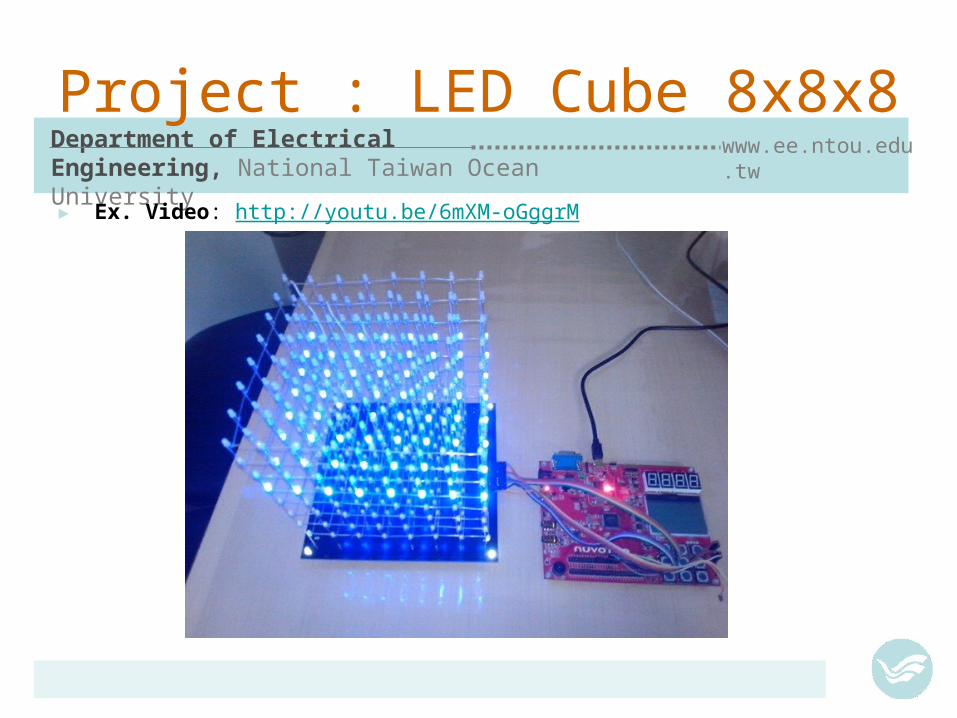
Project : LED Cube 8x8x8
► Ex. Video: http://youtu.be/6mXM-oGggrM

Department of Electrical Engineering, National Taiwan Ocean University
www.ee.ntou.edu.tw
Project : Electronic Safe
► Electronic Safe : http://goods.ruten.com.tw/item/show?21110021890926► Ex.Video : http://youtu.be/PUKqQM0oIIo Samsung Door Lock

Department of Electrical Engineering, National Taiwan Ocean University
www.ee.ntou.edu.tw
Electronic Safe : Functional Description
► Project Objectives– To use Cortex-M0 learning board to control the electronic safe
– To study/trace the PCB & circuit of Electronic Safe
– To draw the flow chart & implement the firmware of MCU
► Functional Description– Input six keycode by pressing 3x3 keypad
– Buzz when each keycode pressed
– Compared with passcode when six keycodes are entered
– If passcode equal to entered keycode, buzz few times and output to (drive electronic magnet) open the door
– SWInt button to change the passcode

Department of Electrical Engineering, National Taiwan Ocean University
www.ee.ntou.edu.tw
Flow Chart
Start
Init_RGBLEDInit_Buzzer
InitLockInit SWInt
Setup HCLK
i=0
OpenKeyPadInitial LCD
Print 2 lines
while(1)
number=Scankey()
number!=0
Y
N
i==4N
Y
print_LCDRGBLED(BLUE)
Buzz(1)
print_LCDRGBLED(GREEN)
Buzz(3)OpenLock
Keycode==
passcodeY N
print_LCDRGBLED(RED)
Buzz(2)CloseLock
print_LCD to clear codei=0

Department of Electrical Engineering, National Taiwan Ocean University
www.ee.ntou.edu.tw
Electronic Safe : Interface Circuit
+6V (1.5V AA x4)Vcc
GroundGnd
GPB15
GPA11
2N2222

Department of Electrical Engineering, National Taiwan Ocean University
www.ee.ntou.edu.tw
GPA15
Electronic Safe : Interface Circuit
+6VGPA12
GPA13
GPA14
Gnd
2N2222

Department of Electrical Engineering, National Taiwan Ocean University
www.ee.ntou.edu.tw
Important Notice !
► This educational material are neither intended nor warranted for usage in systems or equipment, any malfunction or failure of which may cause loss of human life, bodily injury or severe property damage. Such applications are deemed, “Insecure Usage”.
► Insecure usage includes, but is not limited to: equipment for surgical implementation, atomic energy control instruments, airplane or spaceship instruments, the control or operation of dynamic, brake or safety systems designed for vehicular use, traffic signal instruments, all types of safety devices, and other applications intended to support or sustain life.
► All Insecure Usage shall be made at user’s own risk, and in the event that third parties lay claims to the author as a result of customer’s Insecure Usage, the user shall indemnify the damages and liabilities thus incurred by using this material.
► Please note that all lecture and sample codes are subject to change without notice. All the trademarks of products and companies mentioned in this material belong to their respective owners.
Related Documents
![Chemical Resistance Chart for Metal - ARC Industrial … Chloride [CH3CH2Cl] 4 4 4 4 3 4 4 4 4 4 4 4 4 4 4 4 4 2 4 ethylene Dichloride [ClCH2CH2Cl] 4 4 4 4 3 4 4 4 4 4 4 4 4 4 4 4](https://static.cupdf.com/doc/110x72/5ac7280c7f8b9a220b8e82c8/chemical-resistance-chart-for-metal-arc-industrial-chloride-ch3ch2cl-4-4.jpg)