Date of Issue: September 2013 Affected Publication: API RP 4G, Operation, Inspection, Maintenance, and Repair of Drilling and Well Servicing Structures, Fourth Edition, April 2012 ERRATA The forms in Annexes A, B, C and D shall be replaced with the attached forms. A section for Corrosion has been added to each form. MS Excel versions of these forms can also be found here: http://mycommittees.api.org/standards/ecs/sc8/Committee%20Documents/Forms/AllItems.aspx

Welcome message from author
This document is posted to help you gain knowledge. Please leave a comment to let me know what you think about it! Share it to your friends and learn new things together.
Transcript

Date of Issue: September 2013 Affected Publication: API RP 4G, Operation, Inspection, Maintenance, and Repair of Drilling and Well Servicing Structures, Fourth Edition, April 2012
ERRATA The forms in Annexes A, B, C and D shall be replaced with the attached forms. A section for Corrosion has been added to each form.
MS Excel versions of these forms can also be found here:
http://mycommittees.api.org/standards/ecs/sc8/Committee%20Documents/Forms/AllItems.aspx

26
Annex A(informative)
Drilling Mast Visual Inspection Form
The form in this annex is intended for free exchange between owners/operators of the equipment or users of this document.

OPERATION, INSPECTION, MAINTENANCE, AND REPAIR OF DRILLING AND WELL SERVICING STRUCTURES 27
Type of inspection performed (check one box only):
Category III Inspection Category IV Inspection
Company: Rig #:
Date:
Location: Mast Manufacturer:
Date of Manufacture:
Manufacturer's Drawing Available for Use in Inspection: Yes: No:
Manufacturer's Rating: Height:
Mast Serial #:
Mast Type: Telescoping: Cantilevered:
Mast Position: Disassembled: Standing: Lying down:
Mast Nameplate on Structure: Yes: No:
Component Numbers Present: Yes: No:
Inspected By: Representing:
MARKING DAMAGE: At the time of inspection, damaged sections or equipment must be clearly and visibly marked sothat needed repairs may be made. A bright, contrasting spray paint is suggested for this. When repairs are made, thevisible markings should be removed by painting over them. It is also necessary for the inspector to write "None" whenno damage markings are needed, as this is his indication that the item has passed inspection. It is recommended thatinspection be made with assistance of manufacturer's assembly drawing and operating instructions. For items notaccessible or that do not apply, draw a line through the item pertaining to the component.
Drilling Mast
Category III/IV - Visual Field Inspection Form
PURPOSE & SCOPE OF INSPECTION: This report form and inspection procedure was developed as a guide for makingand reporting field inspection in a thorough and uniform manner. The procedure is intended for use by operatingpersonnel (or a designated representative) to the extent that its use satisfies conditions for which an inspection isintended. More detailed and critical inspections may be scheduled periodically, or ordered to supplement a program ofthese inspections; if masts are used in the upper range of their load limits, or if structures may have been subjected tocritical conditions which could effect safe performance. This form is provided strictly as a guide, and the API accepts noliability whatsoever for its use or scope.
Mast—A structural tower comprised of one or more sections and then raised to the operating position. If the unit contains two or more sections, it may be telescoped or unfolded during the erection procedure.

28 API RECOMMENDED PRACTICE 4G
OK X1 Requires immediate attention Provide comments regarding
NA Not applicable X2 Requires attention next move inspected items.
U Unable to access X3 Requires attention next maintenance
M Missing X4 Requires attention when convenient
1.0 Crown Assembly
Make/Model:
1.1 Sheaves
Number of Sheaves: Main Cluster Sheave Diameter:
Fast Line Sheave Diameter:
Condition:
Sheaves:
Grooves in Gage:
Spacers or Seals:
Grease Fittings:
Bearings:
Drilling Line Guards:
1.2 Crown Platform
Decking:
Holes Covered:
Safety Gate:
Ladder Access:
Handrails:
Frame Straight:
Welds:
Bolts and Nuts:
1.3 Crown Support Beams:
Beam Straight:
Pins & Bolts:
Safety Pins/Keepers:
Welds:
1.4 Additional Sheave Assemblies in Crown:
Name:
Condition:
1.5 Pad-eyes Under the Crown Platform:
SWL Marked:
Welds:
Pin Holes
Items that do not need attention should be checked to indicate that the item was inspected. Items that are notapplicable should be marked in the box as "NA" (not applicable). Items that are warped, worn, damaged, crackedwelds, rusted, bent, in need of repair or replacement, or otherwise in need of further attention, mark an "X" in the box and provide comments on the inspected items.
COMMENTS REGARDING INSPECTED ITEMS
DRILLING MASTS

OPERATION, INSPECTION, MAINTENANCE, AND REPAIR OF DRILLING AND WELL SERVICING STRUCTURES 29
1.6 Fall Arrest/Climbing Assist Device Mounting:Support Pole:Base:Sheave Attachment:Weight Bucket Attach:Welds:
1.7 Crown Saver Block(s):Safety Mesh:Safety Cable:Block(s) Condition:Attachment Strapping:Strapping Welds:
Number of Visible Marks Applied:
2.0 Mast Legs:2.1 Front Leg, Drillers Side:
Leg Straight:Pin Connections: Pin Hole(s):Pins:Safety Pins/Keepers:Welds:
2.2 Front Leg, Off Drillers Side:Leg Straight:Pin Connections: Pin Hole(s):Pins:Safety Pins/Keepers:Welds:
2.3 Rear Leg, Drillers Side:Leg Straight:Pin Connections: Pin Hole(s):Pins:Safety Pins / Keepers:Welds:
2.4 Rear Leg, Off Drillers Side:Leg Straight:Pin Connections: Pin Hole(s):Pin(s):Safety Pins/Keepers:Welds:
Number of Visible Marks Applied:
COMMENTS REGARDING INSPECTED ITEMS

30 API RECOMMENDED PRACTICE 4G
3.0 Spreaders (Back Panel Trusses)Members Straight:Bolts:Pin/Bolt Hole(s):Pins:Safety Pins/Keepers:Welds:
Number of Visible Marks Applied:
4.0 Girt(s) and Bracing:Members Straight:Welds:
Number of Visible Marks Applied:
5.0 Mast Feet or PivotsCondition: Pin Hole(s):Pins:Safety Pins/Keepers:Welds:
Number of Visible Marks Applied:
6.0 Deadline Anchor Mounting: (Reference API RP 8B)Supports:Bolts:Anchor Mounting Welds:Brass Inserts:
Number of Visible Marks Applied:
7.0 A-Frame/Gin Pole7.1 Driller's Side Legs:
Leg Straight:Pin Hole(s):Pins:Safety Pins/Keepers:Welds:
7.2 Off Driller's Side Legs:Leg Straight:Pin Hole(s):Pins:Safety Pins/Keepers:Welds:
7.3 Spreaders or Trusses:Members:Welds:
7.4 Upper Connections:Members:Welds:
COMMENTS REGARDING INSPECTED ITEMS

OPERATION, INSPECTION, MAINTENANCE, AND REPAIR OF DRILLING AND WELL SERVICING STRUCTURES 31
7.5 Lower Connections:Pin Connections: Pin Hole(s):Pins:Safety Pins/Keepers:Welds:
Number of Visible Marks Applied:
See Section 10.0 for Raising Sheave Check List.
8.0 Working Platforms:8.1 Pipe Racking Platform:
Frame Straight:Pin Hole(s):Pins:Safety Pins/Keepers:Frame Welds:Working Platform:Landing Platform:Handrails:Ladder Access:Fingers Straight:Finger Welds:Finger Safety Line(s):Hoist Mounting:
Number of Visible Marks Applied:
8.2 Casing Stabbing Board:Frame Straight:Welds:Handrails:Working Platform: Hoisting Assembly:Hoist Mounting:Lower Travel Stops:Pin or Bolt Holes:Pins or Bolts:Safety Pins/Keepers:
Number of Visible Marks Applied:
8.3 Tubing Support/Belly Board:Frame Straight:Welds:Handrails:Pin Holes:Pins:Safety Pins/Keepers:Support Cables:Cable Connections:
Number of Visible Marks Applied:
COMMENTS REGARDING INSPECTED ITEMS

32 API RECOMMENDED PRACTICE 4G
9.0 Ladders:Vertical Rails Straight:Rails in Alignment:Ladder Stand Offs:Stand Off Connections:Rail Welds:Rungs:Rung Welds:Rung Spacing:Access at Rig Floor: Cage:Toe Clearance:
Number of Visible Marks Applied:
10.0 Raising and Telescoping System10.1 Raising Line System—Refer to API Spec 9B, for Specifications:
Wireline:Wireline—Sockets:Pins:Safety Pins/Keepers:Sheaves Turn Freely:Sheaves:Grooves in Gage:Spacers or SealsGrease Fittings:Bearings:Line Guards:Welds:Equalizer Assembly:
Number of Visible Marks Applied:
10.2 Hydraulic or Telescoping System:Hydraulic Cylinders—Raising:
Seals:Main Ram:Cylinder Hinge Points:Hinge Pin Hole(s):Hinge Pins:Safety Pins/Keepers:Hydraulic Hoses:Hose Connections: Bleed Valve:
Hydraulic Cylinder(s) Telescoping:Seals:Main Ram:Cylinder Hinge Points:Pin Hole(s):Pins:Safety Pins/Keepers:Hydraulic Hoses:Hose Connections: Cylinder Stabilizers:Bleed Valve:Lubrication:
COMMENTS REGARDING INSPECTED ITEMS
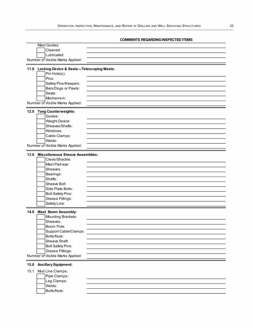
OPERATION, INSPECTION, MAINTENANCE, AND REPAIR OF DRILLING AND WELL SERVICING STRUCTURES 33
Mast Guides:Cleaned:Lubricated:
Number of Visible Marks Applied:
11.0 Locking Device & Seats—Telescoping Masts:Pin Hole(s):Pins:Safety Pins/Keepers:Bars/Dogs or Pawls:Seats:Mechanism:
Number of Visible Marks Applied:
12.0 Tong Counterweights:Guides:Weight Device:Sheaves/Shafts:Wirelines:Cable Clamps:Welds:
Number of Visible Marks Applied:
13.0 Miscellaneous Sheave Assemblies:Clevis/Shackle:Mast Pad-eye:Sheaves:Bearings:Shafts:Sheave Bolt:Side Plate Bolts:Bolt Safety Pins:Grease Fittings:Safety Line:
14.0 Mast Boom Assembly:Mounting Brackets:Sheaves:Boom Pole:Support Cable/Clamps:Bolts/Nuts:Sheave Shaft:Bolt Safety Pins:Grease Fittings:
Number of Visible Marks Applied:
15.0 Ancillary Equipment:
15.1 Mud Line Clamps:Pipe Clamps:Leg Clamps:Welds:Bolts/Nuts:
COMMENTS REGARDING INSPECTED ITEMS

34 API RECOMMENDED PRACTICE 4G
15.2 Gas Vent Line Clamps:Pipe Clamps:Leg Clamps:Welds:Bolts/Nuts:
15.3 Climber Assist System: (See User's Manual for Specific Inspection Requirements)Cable:Cable Attachments:Counter Weight:Sheave/Control Descent Device:
15.4 Fall Arrest System: (See User's Manual for Specific Inspection Requirements)Cable:Cable Attachments:Device Attachment:Sheave/Control Descent Device:
15.5 Mast Escape Device:Mast Attachment:Cable:Device Condition:
15.6 Windwalls/Frames and AttachmentsFrame Condition:Frame Welds:Frame Bolts/PinsMetal Wall Sections:
15.7 Topdrive Mounting System:Rail(s):Pad-eyes:Mounting Brackets:Pins/Bolts:Safety Pins/Keepers:Cables:Block Dollies:Welds:
16.0 Corrosion (refer to Section 7.2):
COMMENTS REGARDING INSPECTED ITEMS
(See User's Manual for Specific Inspection Requirements)

OPERATION, INSPECTION, MAINTENANCE, AND REPAIR OF DRILLING AND WELL SERVICING STRUCTURES 35
17.0 Paint/CoatingCondition:
18.0 Comments, Sketches, and/or Pictures:
Inspector's Signature Date:Owner Representative Signature: Date:

36
Annex B(informative)
Well Servicing Masts Visual Inspection Form
The form in this annex is intended for free exchange between owners/operators of the equipment or users of this document.

OPERATION, INSPECTION, MAINTENANCE, AND REPAIR OF DRILLING AND WELL SERVICING STRUCTURES 37
Type of inspection performed (check one box only):
Category III Inspection Category IV Inspection
Company: Rig #:
Date:
Location: Mast Manufacturer:
Manufacturer's Drawing Available for Use in Inspection: Yes: No:
Manufacturer's Rating: Height:
Mast Serial #:
Mast Type: One Piece Telescoping Folding
Mast Position: Standing Lying down Disassembled
Mast Nameplate on Structure: Yes: No:
Inspected By: Representing:
Well Servicing Masts (Guyed, Carrier\Trailer Mounted)
Category III/IV - Visual Field Inspection Form
PURPOSE & SCOPE OF INSPECTION: This report form and inspection procedure was developed as a guide for makingand reporting field inspection in a thorough and uniform manner. The procedure is intended for use by operatingpersonnel (or a designated representative) to the extent that its use satisfies conditions for which an inspection isintended. More detailed and critical inspections may be scheduled periodically, or ordered to supplement a programof these inspections; if masts are used in the upper range of their load limits, or if structures may have been subjectedto critical conditions which could effect safe performance. This form is provided strictly as a guide, and the API acceptsno liability whatsoever for its use or scope.
MARKING DAMAGE: At the time of inspection, damaged sections or equipment must be clearly and visibly marked sothat needed repairs may be made. A bright, contrasting spray paint is suggested for this. When repairs are made, thevisible markings should be removed by painting over them. It is also necessary for the inspector to write "None" whenno damage markings are needed, as this is his indication that the item has passed inspection. It is recommendedthat inspection be made with assistance of manufacturer's assembly drawing and operating instructions. For itemsnot accessible or that do not apply, draw a line through the item pertaining to the component.

38 API RECOMMENDED PRACTICE 4G
OK X1 Requires immediate attention Provide comments regardingNA Not applicable X2 Requires attention next move inspected items.U Unable to access X3 Requires attention next maintenanceM Missing X4 Requires attention when convenient
1.0 Crown Assembly1.1 Sheaves
Number of Sheaves: Main Cluster Sheave Diameter:
Hoisting Line Size: Fast Line Sheave Diameter:
Condition:Main Sheaves:Fastline Sheaves:Sandline Sheaves:Grooves in Gage:Bearings:Seals:Line Guards: Grease Fittings:Center Pin Locks:Winch Line Sheaves:Retracting Line Sheaves:
Sheave Material Type: Cast IronFab
Steel Phenolic ResinNumber of Visible Marks Applied:
2.0 Crown Block StructureCrown Railing:Crown Frame:Safety Gate:Guyline Support Eyes:Loadline Support Eyes:Sheave Pedestal Mounts:Crown Decking:Fall Protection Mount:Fall Protection Device:
Number of Visible Marks Applied:
3.0 Upper Mast SectionOperator's Side Front Leg:Operator's Side Rear Leg:Off Side Front Leg:Off Side Rear Leg:C Sections:Diagonal Bracing:Back Bracing:Rod Basket Mounts:Tubing Board Mounts:Upper Latch Assembly (LoCotter Keys in Place:Ram Stabilizers:Mast Lighting Mounts:
Number of Visible Marks Applied:
Items that do not need attention should be checked to indicate that the item was inspected. Items that are notapplicable should be marked in the box as "NA" (not applicable). Items that are warped, worn, damaged, crackedwelds, rusted, bent, in need of repair or replacement, or otherwise in need of further attention, mark an "X" in the boxand provide comments on the inspected items.
GUYED MAST
COMMENTS REGARDING INSPECTED ITEMS

OPERATION, INSPECTION, MAINTENANCE, AND REPAIR OF DRILLING AND WELL SERVICING STRUCTURES 39
4.0Operator's Side Front Leg:Operator's Side Rear Leg:Off Side Front Leg:Off Side Rear Leg:C Sections:Diagonal Bracing:Back Bracing:Lower Latch Assembly (Lock):Cotter Keys in Place:Mast Hinge Points:Stand Pipe Mounts:Block Hanging Assembly:Leg Adjustment Screws:Rating Tags in Place:
Number of Visible Marks Applied:
5.0 Tubing BoardTubing Board Frame:Frame Hinge Points:Tail Gate Hinge Points:Left Support Line Anchor:Right Support Line Anchor:Diving Board:Hand Rails:Fingers:Safety Cables on Fingers:Support Cables:
Number of Visible Marks Applied:
6.0 Rod BasketRod Basket Frame:Rod Racks (fingers):Load Line Anchor Points:Rod Rack Hinge Points:
Number of Visible Marks Applied:
7.0 Pipe Racking Platform (Drilling Applications):Frame Straight:Pin Hole(s):PinsSafety Pins/Keepers:Frame Welds:Working Platform:Landing Platform:Handrails:Ladder Access:Fingers Straight:Finger Welds:Finger Safety Line(s):Hoist Mounting:
Number of Visible Marks Applied:
Lower Mast Section
Telescoping Cylinder Stabilizers:
Support Cables:
COMMENTS REGARDING INSPECTED ITEMS

40 API RECOMMENDED PRACTICE 4G
COMMENTS REGARDING INSPECTED ITEMS8.0 Base Mast Section
Base Section Structure:Diagonal Supports:Turnbuckles:Hinge Points:Push Points:Mast Locking Device:Support Beam:Angle Adjustment Screws:Load Adjustment Screws:
Number of Visible Marks Applied:
9.0 Main Hydraulic Ram/Raising Cylinder(Shall be inspected during rig-up/rig-down operation.)
Cylinder Hinge Points:Hydraulic Connections:Hydraulic Hoses:Hinge Pins:Retaining Pins or Locks:Main Ram:Seals:Bleed Valve:
10.0 Telescoping Hydraulic Ram/CylinderCylinder Push Points:Hydraulic Connections:Hydraulic Hoses:Connecting Pins:Retaining Pins or Locks:Telescoping Ram:Seals:Bleed Valve:
11.0 Ladders:Vertical Rails Straight:Rails In Alignment:Ladder Stand Offs:Stand Off Connections:Rail Welds:Rungs/Welds:Rung Spacing:Access at Rig Floor: Toe Clearance:
Number of Visible Marks Applied:
12.0 Tong Counterweights (Drilling Applications):Guides:Weight Device:Sheaves/Shafts:Wirelines:Cable Clamps:Welds:
Number of Visible Marks Applied:

OPERATION, INSPECTION, MAINTENANCE, AND REPAIR OF DRILLING AND WELL SERVICING STRUCTURES 41
COMMENTS REGARDING INSPECTED ITEMS
13.0 Miscellaneous Sheave Assemblies:Clevis/Shackle:Mast Pad-eye:Sheaves:Bearings:Shafts:Sheave Bolt:Side Plate Bolts:Bolt Safety Pins:Grease Fittings:Safety Line:
Number of Visible Marks Applied:
14.0 Carrier ComponentsDead Line Anchor:Rear Jack Beam:Front Jack Beam:Load Line Tiedowns:Load Line Turnbuckles:Load Line Condition:Load Line Size:Tubing Line Condition:Proper Jack Stands:
Number of Visible Marks Applied:
15.0 Corrosion (refer to Section 7.2):
16.0 Paint /CoatingCondition:
17.0 Should additional inspection or NDT be performed? ____________________ If so, please explain: ______________

42 API RECOMMENDED PRACTICE 4G
18.0 Special Comments and/or Pictures:
Inspector's Signature: Date: Owner Representative Signature: Date:

43
Annex C(informative)
Drilling Derrick Visual Inspection Form
The form in this annex is intended for free exchange between owners/operators of the equipment or users of this document.

44 API RECOMMENDED PRACTICE 4G
Type of inspection performed (check one box only):
Category III Inspection Category IV Inspection
Company: Rig #:
Date:
Location: Derrick Manufacturer:
Date of Manufacture:
Manufacturer's Drawing Available for Use in Inspection: Yes: No:
Manufacturer's Rating: Height:
Derrick Serial #:
Derrick Type: Bolted Welded
Type Rig: Platform Jackup Submersible
Semi-submersible Drill Ship
Nameplate on Structure: Yes: No:
Component Numbers Present: Yes: No:
Inspected By: Representing:
Drilling Derrick
Category III / IV - Visual Field Inspection Form
PURPOSE & SCOPE OF INSPECTION: This report form and inspection procedure was developed as a guide for makingand reporting field inspection in a thorough and uniform manner. The procedure is intended for use by operatingpersonnel (or a designated representative) to the extent that its use satisfies conditions for which an inspection isintended. More detailed and critical inspections may be scheduled periodically, or ordered to supplement a program ofthese inspections; if derricks are used in the upper range of their load limits, or if structures may have been subjected tocritical conditions which could effect safe performance. This form is provided strictly as a guide, and the API accepts noliability whatsoever for its use or scope.
Derrick—A semi-permanent structure of square or rectangular cross-section having members that are latticed or trussed on all four sides. This unit must be assembled in the vertical or operation position, as it includes no erection mechanism.
MARKING DAMAGE: At the time of inspection, damaged sections or equipment must be clearly and visibly marked sothat needed repairs may be made. A bright, contrasting spray paint is suggested for this. When repairs are made, thevisible markings should be removed by painting over them. It is also necessary for the inspector to write "None" whenno damage markings are needed, as this is his indication that the item has passed inspection. It is recommended thatinspection be made with assistance of manufacturer's assembly drawing and operating instructions. For items notaccessible or that do not apply, draw a line through the item pertaining to the component.

OPERATION, INSPECTION, MAINTENANCE, AND REPAIR OF DRILLING AND WELL SERVICING STRUCTURES 45
OK X1 Requires immediate attention Provide comments regarding inspec
NA Not applicable X2 Requires attention next move
U Unable to access X3 Requires attention next maintenance
M Missing X4 Requires attention when convenient
1.0 Crown Assembly
Make/Model:
1.1 SheavesNumber of Sheaves: Main Cluster Sheave Dia:
Fast Line Sheave Dia:Condition:Sheaves:Grooves in Gage:Spacers or Seals:Grease Fittings:Bearings:Drilling Line Guards:
1.2 Crown PlatformDecking:Holes Covered:Safety Gate:Ladder Access:Handrails:Frame Straight:Welds:Bolts and Nuts:
1.3 Crown Support Beams:Beam Straight:Pins & Bolts:Safety Pins/Keepers:Welds:
1.4 Additional Sheave Assemblies in Crown: Name:
Condition:
1.5 Pad-eyes Under the Crown Platform:SWL Marked:Welds:Pin Holes
COMMENTS REGARDING INSPECTED ITEMS
DERRICK
Items that do not need attention should be checked to indicate that the item was inspected. Items that are notapplicable should be marked in the box as "NA" (not applicable). Items that are warped, worn, damaged, crackedwelds, rusted, bent, in need of repair or replacement, or otherwise in need of further attention, mark an "X" in the boxand provide comments on the inspected items.

46 API RECOMMENDED PRACTICE 4G
1.6 Fall Arrest/Climbing Assist Device Mounting:Support Pole:Base:Sheave Attachment:Weight Bucket Attach.:Welds:
1.7 Crown Saver Block(s):Safety Mesh:Safety Cable:Block(s) Condition:Attachment Strapping:Strapping Welds:
1.8 A-Frame/Gin Pole:Frame Legs:Bolt Connections:Welds:Access Platform:Ladder:Pad-eyes:
1.9 Top Beams/Water Table:Frame:Welds:Bolt Connections:
Number of Visible Marks Applied:
2.0 Derrick Legs:
2.1 Front Leg, Drillers Side:Leg Straight:Bolt Connections: Splice Connections:Welds:
2.2 Front Leg, Off Drillers Side:Leg Straight:Bolt Connections: Splice Connections:Welds:
2.3 Rear Leg, Drillers Side:Leg Straight:Bolt Connections: Splice Connections:Welds:
2.4 Rear Leg, Off Drillers Side:Leg Straight:Bolt Connections: Splice Connections:Welds:
Number of Visible Marks Applied:
COMMENTS REGARDING INSPECTED ITEMS

OPERATION, INSPECTION, MAINTENANCE, AND REPAIR OF DRILLING AND WELL SERVICING STRUCTURES 47
3.0 Girts & Braces:Members Straight:Bolt Connections:Welds:
Number of Visible Marks Applied:
5.0 Pedestals, Base Plates:Condition: Anchor Bolts:Welds:
Number of Visible Marks Applied:
6.0 Working Platforms:
6.1 Pipe Racking Platform:Frame Straight:Pin Hole(s):PinsSafety Pins/Keepers:Frame Welds:Working Platform:Landing Platform:Handrails:Ladder Access:Fingers Straight:Finger Welds:Finger Safety Line(s)Hoist Mounting:
Number of Visible Marks Applied:
6.2 Casing Stabbing Board:Frame Straight:Welds:Handrails:Working Platform: Hoisting Assembly*:Hoist Mounting:Lower Travel Stops:Pin or Bolt Holes:Pins or Bolts:Safety Pins/Keepers:Ladder Access:
Number of Visible Marks Applied:* See user's manual for specific inspection requirements.
6.3 Tubing Support/Belly Board:Frame Straight:Welds:Handrails:Pin Holes:Pins:Safety Pins/Keepers:
Number of Visible Marks Applied:
COMMENTS REGARDING INSPECTED ITEMS

48 API RECOMMENDED PRACTICE 4G
6.4 Fourble Platform:Handrails:Decking:Bolt Connections:Welds:Safety Gates:
Number of Visible Marks Applied:
7.0 Ladders:Vertical Rails Straight:Rails in Alignment:Ladder Stand Offs:Stand Off Connections:Rail Welds:Rungs:Rung Welds:Rung Spacing:Access at Rig Floor: Cage:Toe Clearance:
Number of Visible Marks Applied:
8.0 Tong Counterweights:Guides:Weight Device:Sheaves:Wirelines:Cable Clamps:Welds:
Number of Visible Marks Applied:
9.0 Miscellaneous Sheave Assemblies:Clevis/Shackle:Derrick Pad-eye:Sheaves:Bearings:Shafts:Sheave Bolt:Side Plate Bolts:Bolt Safety Pins:Grease FittingsSafety Line:
10.0 Ancillary Equipment:
10.1 Mud Line ClampsPipe Clamps:Leg Clamps:Welds:Bolts/Nuts:
COMMENTS REGARDING INSPECTED ITEMS

OPERATION, INSPECTION, MAINTENANCE, AND REPAIR OF DRILLING AND WELL SERVICING STRUCTURES 49
10.2 Gas Vent Line Clamps:Pipe Clamps:Leg Clamps:Welds:Bolt/Nuts:
10.3 Climber Assist System: (See User's Manual for specific inspection requirements.)Cable:Cable Attachments:Counter Weight:Sheave/ControlDescent Device:
10.4 Fall Arrest System: (See User's Manual for specific inspection requirements.)Cable:Cable Attachments:Device Attachment:Sheave/ControlDescent Device:
10.5 Derrick Escape Device:Derrick Attachment:Cable:Device Condition:
10.6 Windwalls, Heat Shields, Frames and AttachmentsFrame Condition:Frame Welds:Frame Bolts/Pins:Metal Wall Sections:
10.7 Topdrive Mounting System:Rail(s)Pad-eyes:Mounting Brackets:Pins/Bolts:Safety Pins/Keepers:Cables:Block Dollies:Welds:
10.8 V-door Rollers/GuidesRollers:Grease Fittings:Welds:Bolts & Nuts:Brackets:
11.0 Corrosion (refer to Section 7.2):
COMMENTS REGARDING INSPECTED ITEMS
(See User's Manual for specific inspection requirements.)

50 API RECOMMENDED PRACTICE 4G
12.0 Paint / CoatingCondition:
13.0 Comments, Sketches, and/or Pictures:
Inspector's Signature: Date:Owner Representative Signature: Date:

51
Annex D(informative)
Substructure Visual Inspection Form
The form in this annex is intended for free exchange between owners/operators of the equipment or users of this document.

52 API RECOMMENDED PRACTICE 4G
Type of inspection performed (check one box only):
Category III Inspection Category IV Inspection
Company: Rig #:Date:
Location: Manufacturer:
Date of Manufacture:
Manufacturer's Rating: Height:
Substructure Serial #:
Substructure Type: Box on Box Self Elevating
Telescoping Offshore
Substructure Position: Elevated: Lowered: Disassembled:
Manufacturer's Drawing Available: Yes: No:
Assembly Drawings Used in Inspection: Yes: No:
Nameplate on Structure: Yes: No:
Component Numbers Present: Yes: No:
Inspected By: Representing:
MARKING DAMAGE: At the time of inspection, damaged sections or equipment must be clearly and visibly marked so thatneeded repairs may be made. A bright, contrasting spray paint is suggested for this. When repairs are made, the visiblemarkings should be removed by painting over them. It is also necessary for the inspector to write "None" when no damagemarkings are needed, as this is his indication that the item has passed inspection. It is recommended that inspection bemade with assistance of manufacturer's assembly drawing and operating instructions. For items not accessible or that donot apply, draw a line through the item pertaining to the component.
Substructure
Category III/IV - Visual Field Inspection Form
PURPOSE & SCOPE OF INSPECTION: This report form and inspection procedure was developed as a guide for makingand reporting field inspection in a thorough and uniform manner. The procedure is intended for use by operatingpersonnel (or a designated representative) to the extent that its use satisfies conditions for which an inspection is intended. More detailed and critical inspections may be scheduled periodically, or ordered to supplement a program of theseinspections; if substructures are used in the upper range of their load limits, or if structures may have been subjected tocritical conditions which could effect safe performance. This form is provided strictly as a guide, and the API accepts noliability whatsoever for its use or scope.

OPERATION, INSPECTION, MAINTENANCE, AND REPAIR OF DRILLING AND WELL SERVICING STRUCTURES 53
OK X1 Requires immediate attention Provide comments regarding inspected items.
NA Not applicable X2 Requires attention next move
U Unable to access X3 Requires attention next maintenance
M Missing X4 Requires attention when convenient
1.0 Shoes, Pedestals:Pin Connections:
Pin Holes:
Bolt Connections:
Bolt Holes:
Pins/Bolts:
Safety Pins:
Support Beams:
Welds:
Number of Visible Marks Applied:
2.0 Floor Area:Floor Plates:
Handrails & Toe Boards:
Handrail Connections:
Setback Material:Floor Bracing:
Welds:
Number of Visible Marks Applied:
3.0 Sub-Spreaders and Rotary Beams:Rotary Beams:
Spreaders:
Pin Connections:
Pin Holes:
Pins:
Pad-eyes:
Welds:
Number of Visible Marks Applied:
4.0 Deadline Anchor Mounting:Supports:
Bolts:
Flooring:
Breakover Assembly:
Handrails:
Welds:
Number of Visible Marks Applied:
COMMENTS REGARDING INSPECTED ITEMS
SUBSTRUCTURES
Items that do not need attention should be checked to indicate that the item was inspected. Items that are not applicableshould be marked in the box as "NA" (not applicable). Items that are warped, worn, damaged, cracked welds, rusted, bent,in need of repair or replacement, or otherwise in need of further attention, mark an "X" in the box and provide comments onthe inspected items.

54 API RECOMMENDED PRACTICE 4G
5.0 Substructure Components:Beams Straight:Cross Braces:Pin/Bolt Holes:Pin/Bolts:Safety Pins:Pull Back Posts:Drawworks Tiedowns:Welds:BOP Anchor Pad-eyes:Pad-eyes:
Number of Visible Marks Applied:
6.0 Engine Foundation:Support Beams:Cross Braces:Pin/Bolt Holes:Pins/Bolts:Safety Pins:Pad-eyes:
Number of Visible Marks Applied:
7.0 Engine Foundation Spreaders:Beams:Cross Braces:Pins / Bolt Holes:Pins / Bolts:Safety Pins:Welds:
Number of Visible Marks Applied:
8.0 BOP Trolley Beams:Beams:Pin Holes:Pins:Safety Pins:Welds:
Number of Visible Marks Applied:
9.0 Raising Equipment:Pin Connections:Pin Holes:Pins:Wirelines:Sheaves:Bearings:Seals:Grease Fittings:Hydraulic Winches:Hydraulic Cylinders:Hydraulic Hoses:Cylinder Hinge:
Number of Visible Marks Applied:
COMMENTS REGARDING INSPECTED ITEMS

OPERATION, INSPECTION, MAINTENANCE, AND REPAIR OF DRILLING AND WELL SERVICING STRUCTURES 55
10.0 Stairs/Landings/Flooring/Handrails:Welds:
Pin/Bolt Holes:
Pins/Bolts:
Floor Plating:
Stair Tread Spacing:
Handrail Sockets:
Number of Visible Marks Applied:
11.0 Paint/CoatingCondition:
12.0 Skidding EquipmentPad-eyes:
Pins:
Beam Clamps:
Jacks:
Jacking Motors:Jacking Rack:
13.0 Corrosion (refer to Section 7.2):
COMMENTS REGARDING INSPECTED ITEMS

56 API RECOMMENDED PRACTICE 4G
14.0 Comments, Drawings, and/or Pictures:
Inspector's Signature: Date:
Owner Representative Signature: Date: __________________________
__________________________
Related Documents