1 4Core1600P35-WiFi+ / 4Core1600P35-WiFi User Manual Version 1.0 Published December 2007 Copyright©2007 ASRock INC. All rights reserved.

Welcome message from author
This document is posted to help you gain knowledge. Please leave a comment to let me know what you think about it! Share it to your friends and learn new things together.
Transcript

11111
4Core1600P35-WiFi+ /4Core1600P35-WiFi
User Manual
Version 1.0Published December 2007
Copyright©2007 ASRock INC. All rights reserved.

22222
Copyright Notice:Copyright Notice:Copyright Notice:Copyright Notice:Copyright Notice:No part of this manual may be reproduced, transcribed, transmitted, or translated inany language, in any form or by any means, except duplication of documentation bythe purchaser for backup purpose, without written consent of ASRock Inc.Products and corporate names appearing in this manual may or may not be regis-tered trademarks or copyrights of their respective companies, and are used only foridentification or explanation and to the owners’ benefit, without intent to infringe.
Disclaimer:Disclaimer:Disclaimer:Disclaimer:Disclaimer:Specifications and information contained in this manual are furnished for informa-tional use only and subject to change without notice, and should not be constructedas a commitment by ASRock. ASRock assumes no responsibility for any errors oromissions that may appear in this manual.With respect to the contents of this manual, ASRock does not provide warranty ofany kind, either expressed or implied, including but not limited to the implied warran-ties or conditions of merchantability or fitness for a particular purpose.In no event shall ASRock, its directors, officers, employees, or agents be liable forany indirect, special, incidental, or consequential damages (including damages forloss of profits, loss of business, loss of data, interruption of business and the like),even if ASRock has been advised of the possibility of such damages arising from anydefect or error in the manual or product.
This device complies with Part 15 of the FCC Rules. Operation is subject to thefollowing two conditions:(1) this device may not cause harmful interference, and(2) this device must accept any interference received, including interference that
may cause undesired operation.
CALIFORNIA, USA ONLYThe Lithium battery adopted on this motherboard contains Perchlorate, a toxicsubstance controlled in Perchlorate Best Management Practices (BMP) regulationspassed by the California Legislature. When you discard the Lithium battery inCalifornia, USA, please follow the related regulations in advance.“Perchlorate Material-special handling may apply, seewww.dtsc.ca.gov/hazardouswaste/perchlorate”
ASRock Website: http://www.asrock.com

33333
ContentsContentsContentsContentsContents1 Introduction1 Introduction1 Introduction1 Introduction1 Introduction ............................................................................................................................................................................................................................................................... 5 5 5 5 5
1.1 Package Contents .......................................................... 51.2 Specifications ................................................................. 61.3 Minimum Hardware Requirement Table for Windows®
VistaTM Premium 2008 and Basic Logo......................... 101.4 Motherboard Layout (4Core1600P35-WiFi+) ................... 111.5 Motherboard Layout (4Core1600P35-WiFi) ..................... 121.6 ASRock 1394_eSATAII I/O Plus (4Core1600P35-WiFi+) . 131.7 ASRock 8CH_eSATAII I/O Plus (4Core1600P35-WiFi) .... 141.8 ASRock WiFi-802.11g Module Specifications ................. 15
2 Installation2 Installation2 Installation2 Installation2 Installation ......................................................................................................................................................................................................................................................................... 16 16 16 16 162.1 Screw Holes ................................................................... 162.2 Pre-installation Precautions ............................................ 162.3 CPU Installation .............................................................. 172.4 Installation of Heatsink and CPU fan ............................... 192.5 Installation of Memory Modules (DIMM) ......................... 202.6 Expansion Slots (PCI and PCI Express Slots) ..................... 232.7 CrossFireTM Operation Guide .......................................... 232.8 Surround Display Feature ............................................... 272.9 Jumpers Setup ............................................................... 282.10 Onboard Headers and Connectors .................................. 302.11 HDMI_SPDIF Header Connection Guide ......................... 362.12 eSATAII Interface Introduction ......................................... 372.13 SATAII Hard Disk Setup Guide ........................................ 402.14 Serial ATA (SATA) / Serial ATAII (SATAII) Hard Disks Installation ...................................................................... 412.15 Hot Plug and Hot Swap Functions for SATA / SATAII
HDDs and eSATAII Devices ......................................... 422.16 SATA / SATAII HDD Hot Plug Feature and Operation Guide ............................................................................. 432.17 Driver Installation Guide ................................................... 452.18 Installing Windows® XP / XP 64-bit / VistaTM / VistaTM
64-bit With RAID Functions ............................................ 452.18.1 Installing Windows® XP / XP 64-bit With RAID Functions ............................................................ 452.18.2 Setting Up a “RAID Ready” System .................... 462.18.3 Migrating a “RAID Ready” System to RAID 0, RAID 1 or RAID 5 ................................................ 472.18.4 Installing Windows® VistaTM / VistaTM 64-bit With RAID Functions ................................................... 48

44444
2.19 Installing Windows® 2000 / XP / XP 64-bit / VistaTM / VistaTM 64-bit Without RAID Functions ........................... 49
2.19.1 Installing Windows® 2000 / XP / XP 64-bit Without RAID Functions ................................................... 492.19.2 Installing Windows® VistaTM / VistaTM 64-bit Without RAID Functions ................................................... 50
2.20 DTS Operation Guide .................................................. 512.21 Untied Overclocking Technology ................................... 53
3 BIOS S3 BIOS S3 BIOS S3 BIOS S3 BIOS SETUP UTILITYETUP UTILITYETUP UTILITYETUP UTILITYETUP UTILITY .................................................................................................................................................................................................................. 54 54 54 54 543.1 Introduction ..................................................................... 54
3.1.1 BIOS Menu Bar ..................................................... 543.1.2 Navigation Keys .................................................... 55
3.2 Main Screen ................................................................... 553.3 Advanced Screen ............................................................ 56
3.3.1 CPU Configuration ................................................ 573.3.2 Chipset Configuration ............................................ 593.3.3 ACPI Configuration ................................................ 613.3.4 IDE Configuration .................................................. 623.3.5 PCIPnP Configuration ........................................... 653.3.6 Floppy Configuration ............................................. 663.3.7 Super IO Configuration .......................................... 663.3.8 USB Configuration ................................................ 68
3.4 Hardware Health Event Monitoring Screen...................... 683.5 Boot Screen ................................................................... 69
3.5.1 Boot Settings Configuration ................................... 703.6 Security Screen .............................................................. 703.7 Exit Screen .................................................................... 71
4 Software Support4 Software Support4 Software Support4 Software Support4 Software Support .................................................................................................................................................................................................................. 72 72 72 72 724.1 Install Operating System ................................................ 724.2 Support CD Information ................................................... 72
4.2.1 Running Support CD ............................................. 724.2.2 Drivers Menu ......................................................... 724.2.3 Utilities Menu ........................................................ 724.2.4 Contact Information ............................................... 72

55555
Chapter 1: IntroductionChapter 1: IntroductionChapter 1: IntroductionChapter 1: IntroductionChapter 1: IntroductionThank you for purchasing ASRock 4Core1600P35-WiFi+ / 4Core1600P35-WiFimotherboard, a reliable motherboard produced under ASRock’s consistently stringentquality control. It delivers excellent performance with robust design conforming to ASRock’scommitment to quality and endurance.In this manual, chapter 1 and 2 contain introduction of the motherboard and step-by-stepguide to the hardware installation. Chapter 3 and 4 contain the configuration guide toBIOS setup and information of the Support CD.
Because the motherboard specifications and the BIOS software mightbe updated, the content of this manual will be subject to change withoutnotice. In case any modifications of this manual occur, the updatedversion will be available on ASRock website without further notice. Youmay find the latest VGA cards and CPU support lists on ASRock websiteas well. ASRock website http://www.asrock.comIf you require technical support related to this motherboard, please visitour website for specific information about the model you are using.www.asrock.com/support/index.asp
1.1 P1.1 P1.1 P1.1 P1.1 Packackackackackage Contentsage Contentsage Contentsage Contentsage ContentsASRock 4Core1600P35-WiFi+ / 4Core1600P35-WiFi Motherboard
(ATX Form Factor: 12.0-in x 9.6-in, 30.5 cm x 24.4 cm)ASRock 4Core1600P35-WiFi+ / 4Core1600P35-WiFi Quick Installation GuideASRock 4Core1600P35-WiFi+ / 4Core1600P35-WiFi Support CDASRock WiFi-802.11g Module Operation Guide
Motherboard AccessoriesOne 80-conductor Ultra ATA 66/100/133 IDE Ribbon CableOne Ribbon Cable for a 3.5-in Floppy DriveFour Serial ATA (SATA) Data Cables (Optional)One Serial ATA (SATA) HDD Power Cable (Optional)One HDMI_SPDIF Cable (Optional)One “ASRock 1394_eSATAII I/O Plus” I/O Panel Shield (4Core1600P35-WiFi+)One “ASRock 8CH_eSATAII I/O Plus” I/O Panel Shield (4Core1600P35-WiFi)
WiFi AccessoriesOne ASRock WiFi-802.11g ModuleOne AntennaOne WiFi Bracket

66666
1 .21 .21 .21 .21 .2 SpecificationsSpecificationsSpecificationsSpecificationsSpecifications
Platform - ATX Form Factor: 12.0-in x 9.6-in, 30.5 cm x 24.4 cm- All Solid Capacitor design
CPU - LGA 775 for Intel® CoreTM 2 Extreme / CoreTM 2 Quad / CoreTM
2 Duo / Pentium® Dual Core / Celeron®, supporting Penryn Quad Core Yorkfield and Dual Core Wolfdale processors- Compatible with all FSB1600/1333/1066/800MHz CPUs (see CAUTION 1)- Supports Hyper-Threading Technology (see CAUTION 2)- Supports Untied Overclocking Technology (see CAUTION 3)- Supports EM64T CPU
Chipset - Northbridge: Intel® P35- Southbridge: Intel® ICH9R
Memory - Dual Channel DDR3/DDR2 Memory Technology (see CAUTION 4)- 2 x DDR3 DIMM slots (green)- Support DDR3 1333/1066/800 non-ECC, un-buffered memory (see CAUTION 5)- Max. capacity: 4GB (see CAUTION 6)- 4 x DDR2 DIMM slots (yellow and orange)- Support DDR2 1066/800/667 non-ECC, un-buffered memory (see CAUTION 5)- Max. capacity: 8GB (see CAUTION 6)
Expansion Slot - Supports ATITM CrossFireTM
- 1 x PCI Express x16 slot- 1 x AGI Express slot (PCI Express x4)- 3 x PCI slots
Audio 4Core1600P35-WiFi+- 7.1 CH Windows® VistaTM Premium Level HD Audio with Content Protection- DAC with 110dB dynamic range (ALC890 Audio Codec)- DTS (Digital Theater Systems) support (see CAUTION 7)4Core1600P35-WiFi- 7.1 CH Windows® VistaTM Premium Level HD Audio with Content Protection- DAC with 110dB dynamic range (ALC890 Audio Codec)
LAN - PCIE x1 Gigabit LAN 10/100/1000 Mb/s- Realtek RTL8111B/RTL8111C- Supports Wake-On-LAN

77777
Wireless LAN - ASRock WiFi-802.11g module- 54Mbps IEEE 802.11g / 11Mbps IEEE 802.11b- Supports Software Access Point mode (AP mode) and Station mode (Infrastructure mode and Ad-hoc mode)
Rear Panel I/O 4Core1600P35-WiFi+ASRock 1394_eSATAII I/O Plus- 1 x PS/2 Mouse Port- 1 x PS/2 Keyboard Port- 1 x Serial Port: COM1- 1 x Parallel Port (ECP/EPP Support)- 4 x Ready-to-Use USB 2.0 Ports- 1 x eSATAII Port- 1 x RJ-45 LAN Port- 2 x RJ-45 LAN Port LED (ACT/LINK LED and SPEED LED)- 1 x IEEE 1394 Port- HD Audio Jack: Side Speaker/Rear Speaker/Central/Bass/ Line in/Front Speaker/Microphone (see CAUTION 8)4Core1600P35-WiFiASRock 8CH_eSATAII I/O Plus- 1 x PS/2 Mouse Port- 1 x PS/2 Keyboard Port- 1 x Serial Port: COM1- 1 x Parallel Port (ECP/EPP Support)- 4 x Ready-to-Use USB 2.0 Ports- 1 x eSATAII Port- 1 x RJ-45 LAN Port- 2 x RJ-45 LAN Port LED (ACT/LINK LED and SPEED LED)- HD Audio Jack: Side Speaker/Rear Speaker/Central/Bass/ Line in/Front Speaker/Microphone (see CAUTION 8)
Connector - 6 x SATAII 3.0Gb/s connectors, support RAID (RAID 0, RAID 1, RAID 10, RAID 5 and Intel Matrix Storage), NCQ, AHCI and “Hot Plug” functions (see CAUTION 9)- 1 x eSATAII 3.0Gb/s connector (shared with 1 SATAII connector) (see CAUTION 10)- 1 x ATA133 IDE connector (supports 2 x IDE devices)- 1 x Floppy connector- 1 x DeskExpress Hot Plug Detection header- 1 x HDMI_SPDIF header- 1 x IEEE 1394 header (4Core1600P35-WiFi+)- CPU/Chassis FAN connector
88888
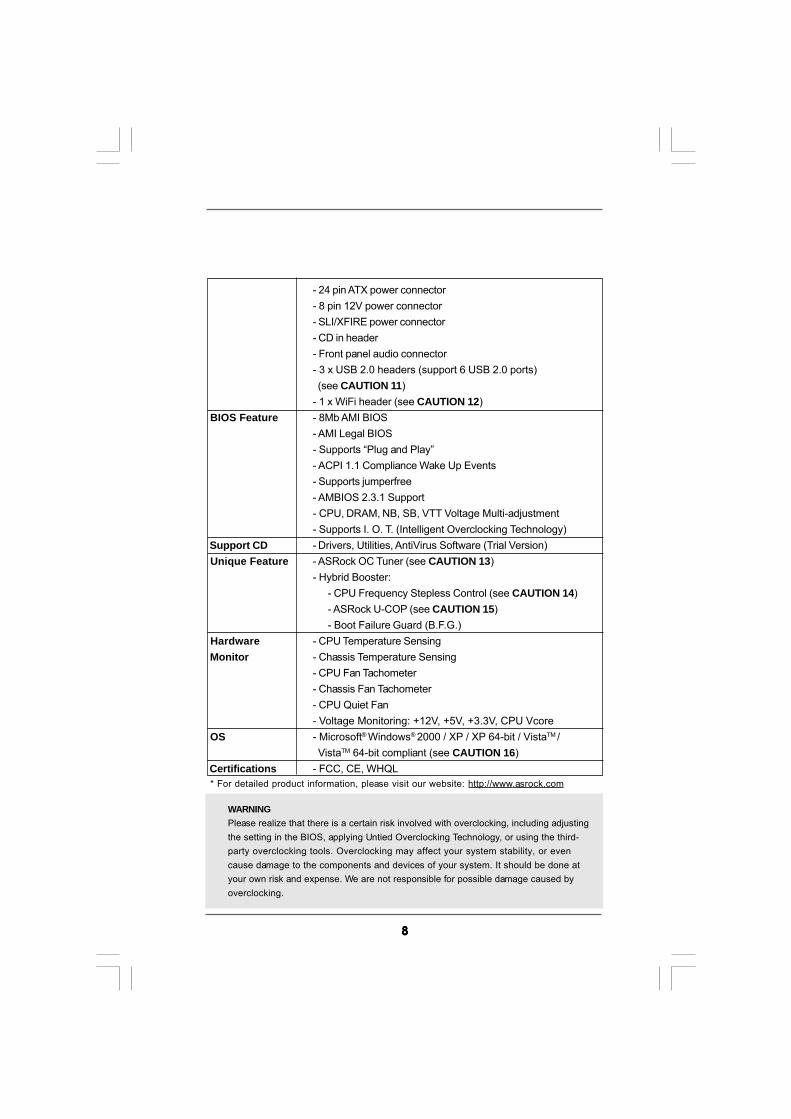
- 24 pin ATX power connector- 8 pin 12V power connector- SLI/XFIRE power connector- CD in header- Front panel audio connector- 3 x USB 2.0 headers (support 6 USB 2.0 ports) (see CAUTION 11)- 1 x WiFi header (see CAUTION 12)
BIOS Feature - 8Mb AMI BIOS- AMI Legal BIOS- Supports “Plug and Play”- ACPI 1.1 Compliance Wake Up Events- Supports jumperfree- AMBIOS 2.3.1 Support- CPU, DRAM, NB, SB, VTT Voltage Multi-adjustment- Supports I. O. T. (Intelligent Overclocking Technology)
Support CD - Drivers, Utilities, AntiVirus Software (Trial Version) Unique Feature - ASRock OC Tuner (see CAUTION 13)
- Hybrid Booster:- CPU Frequency Stepless Control (see CAUTION 14)- ASRock U-COP (see CAUTION 15)- Boot Failure Guard (B.F.G.)
Hardware - CPU Temperature Sensing Monitor - Chassis Temperature Sensing
- CPU Fan Tachometer- Chassis Fan Tachometer- CPU Quiet Fan- Voltage Monitoring: +12V, +5V, +3.3V, CPU Vcore
OS - Microsoft® Windows® 2000 / XP / XP 64-bit / VistaTM / VistaTM 64-bit compliant (see CAUTION 16)
Certifications - FCC, CE, WHQL * For detailed product information, please visit our website: http://www.asrock.com
WARNINGPlease realize that there is a certain risk involved with overclocking, including adjustingthe setting in the BIOS, applying Untied Overclocking Technology, or using the third-party overclocking tools. Overclocking may affect your system stability, or evencause damage to the components and devices of your system. It should be done atyour own risk and expense. We are not responsible for possible damage caused byoverclocking.
99999
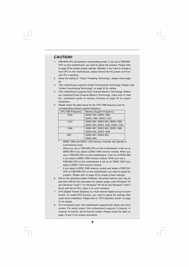
CAUTION!1. FSB1600-CPU will operate in overclocking mode. If you use a FSB1600-
CPU on this motherboard, you need to adjust the jumpers. Please referto page 29 for proper jumper settings. Besides, if you want to change anew CPU on this motherboard, please remove the AC power cord fromyour PC in advance.
2. About the setting of “Hyper Threading Technology”, please check page56.
3. This motherboard supports Untied Overclocking Technology. Please read“Untied Overclocking Technology” on page 53 for details.
4. This motherboard supports Dual Channel Memory Technology. Beforeyou implement Dual Channel Memory Technology, make sure to readthe installation guide of memory modules on page 20 for properinstallation.
5. Please check the table below for the CPU FSB frequency and itscorresponding memory support frequency.
CPU FSB Frequency Memory Support Frequency1600 DDR2 800, DDR2 1066,
DDR3 1066, DDR3 13331333 DDR2 667, DDR2 800, DDR2 1066,
DDR3 800, DDR3 1066, DDR3 13331066 DDR2 667, DDR2 800, DDR2 1066,
DDR3 800, DDR3 1066800 DDR2 667, DDR2 800,
DDR3 800* DDR2 1066 and DDR3 1333 memory modules will operate in
overclocking mode.* When you use a FSB1600-CPU on this motherboard, it will run at
DDR2 960 if you adopt a DDR2 1066 memory module. When youuse a FSB1600-CPU on this motherboard, it will run at DDR3 960if you adopt a DDR3 1066 memory module. When you use aFSB1600-CPU on this motherboard, it will run at DDR3 1280 if youadopt a DDR3 1333 memory module.
* If you adopt a DDR2 1066 memory module and adopt a FSB1333-CPU or FSB1066-CPU on this motherboard, you need to adjust thejumpers. Please refer to page 29 for proper jumper settings.
6. Due to the operating system limitation, the actual memory size may beless than 4GB for the reservation for system usage under Windows® XPand Windows® VistaTM. For Windows® XP 64-bit and Windows® VistaTM
64-bit with 64-bit CPU, there is no such limitation.7. DTS (Digital Theater Systems) is a multi-channel digital surround sound
format. To enable DTS function, you need to adjust the settings afteraudio driver installation. Please refer to “DTS Operation Guide” on page51 for details.
8. For microphone input, this motherboard supports both stereo and monomodes. For audio output, this motherboard supports 2-channel, 4-channel, 6-channel, and 8-channel modes. Please check the table onpage 13 and 14 for proper connection.

1010101010
1.31.31.31.31.3 Minimum Hardware RMinimum Hardware RMinimum Hardware RMinimum Hardware RMinimum Hardware Requirement Tequirement Tequirement Tequirement Tequirement Table for Wable for Wable for Wable for Wable for Windowsindowsindowsindowsindows®®®®®
VistaVistaVistaVistaVistaTMTMTMTMTM Premium 2008 and Basic Logo Premium 2008 and Basic Logo Premium 2008 and Basic Logo Premium 2008 and Basic Logo Premium 2008 and Basic LogoFor system integrators and users who purchase this motherboard andplan to submit Windows® VistaTM Premium 2008 and Basic logo, pleasefollow below table for minimum hardware requirements.
CPU Celeron 420Memory 1GB system memory (Premium)
512MB Single Channel (Basic)VGA DX10 with WDDM Driver
with 128bit VGA memory (Premium)with 64bit VGA memory (Basic)
* After June 1, 2008, all Windows® VistaTM systems are required to meet above minimum hardware requirements in order to qualify for Windows® VistaTM
Premium 2008 logo.
9. Before installing SATAII hard disk to SATAII connector, please read the“SATAII Hard Disk Setup Guide” on page 40 to adjust your SATAII harddisk drive to SATAII mode. You can also connect SATA hard disk to SATAIIconnector directly.
10. This motherboard supports eSATAII interface, the external SATAIIspecification. Please read “eSATAII Interface Introduction” on page 37for details about eSATAII and eSATAII installation procedures.
11. Power Management for USB 2.0 works fine under Microsoft® Windows®
VistaTM 64-bit / VistaTM / XP 64-bit / XP SP1 or SP2 / 2000 SP4.12. WiFi header supports WiFi+AP function with ASRock WiFi-802.11g or
WiFi-802.11n module, an easy-to-use wireless local area network(WLAN) adapter. It allows you to create a wireless environment andenjoy the convenience of wireless network connectivity.
13. It is a user-friendly ASRock overclocking tool which allows you to surveilyour system by hardware monitor function and overclock your hardwaredevices to get the best system performance under Windows®
environment. Please visit our website for the operation procedures ofASRock OC Tuner. ASRock website: http://www.asrock.com
14. Although this motherboard offers stepless control, it is not recom-mended to perform over-clocking. Frequencies other than the recom-mended CPU bus frequencies may cause the instability of the systemor damage the CPU.
15. While CPU overheat is detected, the system will automatically shutdown.Before you resume the system, please check if the CPU fan on themotherboard functions properly and unplug the power cord, then plug itback again. To improve heat dissipation, remember to spray thermalgrease between the CPU and the heatsink when you install the PCsystem.
16. ASRock WiFi-802.11g module and RAID / AHCI functions are notsupported under Windows® 2000 OS. It is recommended to use IDEmode under Windows® 2000. Please refer to page 62 for detailed setup.

1111111111
1.4 Motherboard L1.4 Motherboard L1.4 Motherboard L1.4 Motherboard L1.4 Motherboard Layout (4Core1600P35-ayout (4Core1600P35-ayout (4Core1600P35-ayout (4Core1600P35-ayout (4Core1600P35-WWWWWiFiFiFiFiFi+)i+)i+)i+)i+)
IntelP35
Chipset
IntelICH9R
AT
XP
WR
1
CD1
ATX12V1
1
PS2_USB_PWR1
SuperI/O
8MbBIOS
LANPHY
AUDIOCODEC
PCIE1
CPU_FAN1
CM
OS
Ba
ttery
PCIEXPRESS
4Cor
e160
0P35
-WiF
i+
DD
R2
10
66
Qu
ad
Co
reC
PU
IDE1
CLRCMOS1
1
CH
A_
FA
N1
FLOPPY1
1
HD_AUDIO1
HDLED RESET
PLED PWRBTN
SPEAKER1
1
PANEL11
WIFI
30
.5c
m(1
2.0
in)
24.4cm (9.6 in)
1 2 3 4 5 6 7 8
9
10
11
12131415
16
2425 23 1718192021222627282930
31
32
DD
RII
_1
(64
bit
,2
40
-pin
mo
du
le)
DD
RII
_2
(64
bit
,2
40
-pin
mo
du
le)Ro
HS
Wo
lfd
ale
Du
alC
ha
nn
el
7.1
CH
HD
SATAII
1
HDMI_SPDIF1 IR1
1
USB4_5
11
Yo
rkfi
eld
Gig
ab
itL
AN
SATAII_3 (Port2)SATAII_4 (Port3)
FS
B1
60
0
FSB1
1
FSB2
1
FSB3
1
1
To
p:
SID
ES
PK
Ce
nte
r:
RE
AR
SP
K
Bo
ttom
:C
TR
BA
SS
To
p:
LIN
EIN
Ce
nte
r:
FR
ON
T
Bo
ttom
:M
ICIN
AGI_EXPRESS1
PCI1
PCI2
PCI3
DD
R3
_A
1(6
4b
it,2
40
-pin
mo
du
le)
DD
RII
_3
(64
bit
,2
40
-pin
mo
du
le)
DD
RII
_4
(64
bit
,2
40
-pin
mo
du
le)
DD
R3
_B
1(6
4b
it,2
40
-pin
mo
du
le)
USB6_7
11
USB8_9
11
SATAII_5 (Port4)SATAII_6 (Port5)
SATAII_1 (Port0)SATAII_2 (Port1)
DD
R3
13
33
US
B2
.0e
SA
TA
II
ESATAII
RAID
AT
A1
33
SL
I/X
FIR
E_
PW
R1
PAR
AL
LE
LP
OR
T
CO
M1
PS
2
Mo
us
e
PS
2K
ey
bo
ard
ES
ATA
II
USB 2.0T: USB0B: USB1
Top:RJ-45
USB 2.0T: USB2B: USB3
33
343536
Top:IEEE1394
FRONT_1394
11
3738
39
1 PS2_USB_PWR1 Jumper 20 USB 2.0 Header (USB6_7, Blue)2 ATX 12V Connector (ATX12V1) 21 USB 2.0 Header (USB4_5, Blue)3 CPU Fan Connector (CPU_FAN1) 22 USB 2.0 Header (USB8_9, Blue)4 775-Pin CPU Socket 23 South Bridge Controller5 North Bridge Controller 24 SPI BIOS Chip6 2 x 240-pin DDR2 DIMM Slots 25 Front Panel IEEE 1394 Header
(Dual Channel A: DDRII_1, DDRII_3; Yellow) (FRONT_1394)7 2 x 240-pin DDR2 DIMM Slots 26 WiFi Header (WiFi)
(Dual Channel B: DDRII_2, DDRII_4; Orange) 27 DeskExpress Hot Plug Detection Header8 2 x 240-pin DDR3 DIMM Slots (IR1)
(Dual Channel C: DDR3_A1, DDR3_B1; Green) 28 Floppy Connector (FLOPPY1)9 IDE1 Connector (IDE1, Blue) 29 HDMI_SPDIF Header (HDMI_SPDIF1)10 Clear CMOS Jumper (CLRCMOS1) 30 Front Panel Audio Header (HD_AUDIO1)11 SATAII Connector (SATAII_5 (Port4), Red) 31 Internal Audio Connector: CD1 (Black)12 SATAII Connector (SATAII_1 (Port0), Red) 32 PCI Slots (PCI1 - 3)13 Chassis Fan Connector (CHA_FAN1) 33 AGI Express Slot (AGI_EXPRESS1)14 SATAII Connector (SATAII_2 (Port1), Red) 34 FSB1 Jumper15 Chassis Speaker Header (SPEAKER 1) 35 FSB2 / FSB3 Jumpers16 System Panel Header (PANEL1) 36 PCI Express x16 Slot (PCIE1)17 SATAII Connector (SATAII_3 (Port2), Red) 37 SLI / XFIRE Power Connector18 SATAII Connector (SATAII_4 (Port3), Red) 38 ATX Power Connector (ATXPWR1)19 SATAII Connector (SATAII_6 (Port5), Orange) 39 eSATAII Connector (eSATAII)

1212121212
1.5 Motherboard L1.5 Motherboard L1.5 Motherboard L1.5 Motherboard L1.5 Motherboard Layout (4Core1600P35-ayout (4Core1600P35-ayout (4Core1600P35-ayout (4Core1600P35-ayout (4Core1600P35-WWWWWiFiFiFiFiFi)i)i)i)i)
IntelP35
Chipset
IntelICH9R
AT
XP
WR
1
CD1
ATX12V1
1
PS2_USB_PWR1
SuperI/O
8MbBIOS
LANPHY
AUDIOCODEC
PCIE1
CPU_FAN1
CM
OS
Ba
ttery
PCIEXPRESS
4Cor
e160
0P35
-WiF
i
DD
R2
10
66
Qu
ad
Co
reC
PU
IDE1
CLRCMOS1
1
CH
A_
FA
N1
FLOPPY1
1
HD_AUDIO1
HDLED RESET
PLED PWRBTN
SPEAKER1
1
PANEL11
WIFI
30
.5c
m(1
2.0
in)
24.4cm (9.6 in)
1 2 3 4 5 6 7 8
9
10
11
12131415
16
2425 23 17181920212226272829
30
31
32
DD
RII
_1
(64
bit
,2
40
-pin
mo
du
le)
DD
RII
_2
(64
bit
,2
40
-pin
mo
du
le)Ro
HS
Wo
lfd
ale
Du
alC
ha
nn
el
7.1
CH
HD
SATAII
1
HDMI_SPDIF1 IR1
1
USB4_5
11
Yo
rkfi
eld
Gig
ab
itL
AN
SATAII_3 (Port2)SATAII_4 (Port3)
FS
B1
60
0
FSB1
1
FSB2
1
FSB3
1
1
To
p:
SID
ES
PK
Ce
nte
r:
RE
AR
SP
K
Bo
ttom
:C
TR
BA
SS
To
p:
LIN
EIN
Ce
nte
r:
FR
ON
T
Bo
ttom
:M
ICIN
AGI_EXPRESS1
PCI1
PCI2
PCI3
DD
R3
_A
1(6
4b
it,
24
0-p
inm
od
ule
)
DD
RII
_3
(64
bit
,2
40
-pin
mo
du
le)
DD
RII
_4
(64
bit
,2
40
-pin
mo
du
le)
DD
R3
_B
1(6
4b
it,
24
0-p
inm
od
ule
)
USB6_7
11
USB8_9
11
SATAII_5 (Port4)SATAII_6 (Port5)
SATAII_1 (Port0)SATAII_2 (Port1)
DD
R3
13
33
US
B2
.0e
SA
TA
II
ESATAII
RAID
AT
A1
33
SL
I/X
FIR
E_
PW
R1
PAR
AL
LE
LP
OR
T
CO
M1
PS
2
Mo
us
e
PS
2K
ey
bo
ard
ES
ATA
II
USB 2.0T: USB0B: USB1
Top:RJ-45
USB 2.0T: USB2B: USB3
333435
3637
38
1 PS2_USB_PWR1 Jumper 20 USB 2.0 Header (USB6_7, Blue)2 ATX 12V Connector (ATX12V1) 21 USB 2.0 Header (USB4_5, Blue)3 CPU Fan Connector (CPU_FAN1) 22 USB 2.0 Header (USB8_9, Blue)4 775-Pin CPU Socket 23 South Bridge Controller5 North Bridge Controller 24 SPI BIOS Chip6 2 x 240-pin DDR2 DIMM Slots 25 WiFi Header (WiFi)
(Dual Channel A: DDRII_1, DDRII_3; Yellow) 26 DeskExpress Hot Plug Detection Header7 2 x 240-pin DDR2 DIMM Slots (IR1)
(Dual Channel B: DDRII_2, DDRII_4; Orange) 27 Floppy Connector (FLOPPY1)8 2 x 240-pin DDR3 DIMM Slots 28 HDMI_SPDIF Header (HDMI_SPDIF1)
(Dual Channel C: DDR3_A1, DDR3_B1; Green) 29 Front Panel Audio Header (HD_AUDIO1)9 IDE1 Connector (IDE1, Blue) 30 Internal Audio Connector: CD1 (Black)10 Clear CMOS Jumper (CLRCMOS1) 31 PCI Slots (PCI1 - 3)11 SATAII Connector (SATAII_5 (Port4), Red) 32 AGI Express Slot (AGI_EXPRESS1)12 SATAII Connector (SATAII_1 (Port0), Red) 33 FSB1 Jumper13 Chassis Fan Connector (CHA_FAN1) 34 FSB2 / FSB3 Jumpers14 SATAII Connector (SATAII_2 (Port1), Red) 35 PCI Express x16 Slot (PCIE1)15 Chassis Speaker Header (SPEAKER 1) 36 SLI / XFIRE Power Connector16 System Panel Header (PANEL1) 37 ATX Power Connector (ATXPWR1)17 SATAII Connector (SATAII_3 (Port2), Red) 38 eSATAII Connector (eSATAII)18 SATAII Connector (SATAII_4 (Port3), Red)19 SATAII Connector (SATAII_6 (Port5), Orange)
1313131313
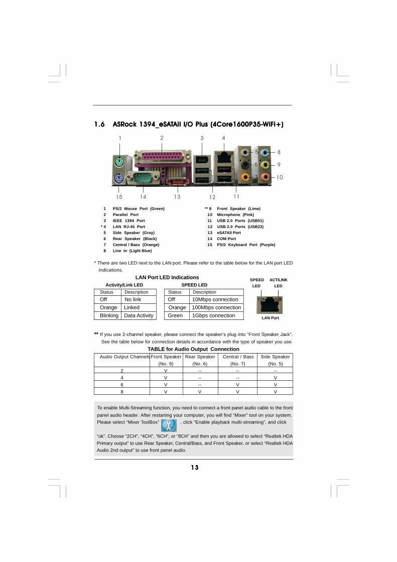
1.61.61.61.61.6 ASRASRASRASRASRock 1394_eSAock 1394_eSAock 1394_eSAock 1394_eSAock 1394_eSATTTTTAII I/O Plus (4Core1600P35-AII I/O Plus (4Core1600P35-AII I/O Plus (4Core1600P35-AII I/O Plus (4Core1600P35-AII I/O Plus (4Core1600P35-WWWWWiFiFiFiFiFi+)i+)i+)i+)i+)
1 PS/2 Mouse Port (Green) ** 9 Front Speaker (Lime)2 Parallel Port 10 Microphone (Pink)3 IEEE 1394 Port 11 USB 2.0 Ports (USB01)
* 4 LAN RJ-45 Port 12 USB 2.0 Ports (USB23)5 Side Speaker (Gray) 13 eSATAII Port6 Rear Speaker (Black) 14 COM Port7 Central / Bass (Orange) 15 PS/2 Keyboard Port (Purple)8 Line In (Light Blue)
To enable Multi-Streaming function, you need to connect a front panel audio cable to the front panel audio header. After restarting your computer, you will find “Mixer” tool on your system. Please select “Mixer ToolBox” , click “Enable playback multi-streaming”, and click
“ok”. Choose “2CH”, “4CH”, “6CH”, or “8CH” and then you are allowed to select “Realtek HDA Primary output” to use Rear Speaker, Central/Bass, and Front Speaker, or select “Realtek HDA Audio 2nd output” to use front panel audio.
6
7
1 2 43
5 8
9
10
1112131415
** If you use 2-channel speaker, please connect the speaker’s plug into “Front Speaker Jack”. See the table below for connection details in accordance with the type of speaker you use.
TABLE for Audio Output ConnectionAudio Output ChannelsFront Speaker Rear Speaker Central / Bass Side Speaker
(No. 9) (No. 6) (No. 7) (No. 5)2 V -- -- --4 V -- -- V6 V -- V V8 V V V V
* There are two LED next to the LAN port. Please refer to the table below for the LAN port LED indications.
LAN Port LED Indications Activity/Link LED SPEED LEDStatus Description Status DescriptionOff No link Off 10Mbps connectionOrange Linked Orange 100Mbps connectionBlinking Data Activity Green 1Gbps connection LAN Port
ACT/LINK LED
SPEED LED
1414141414
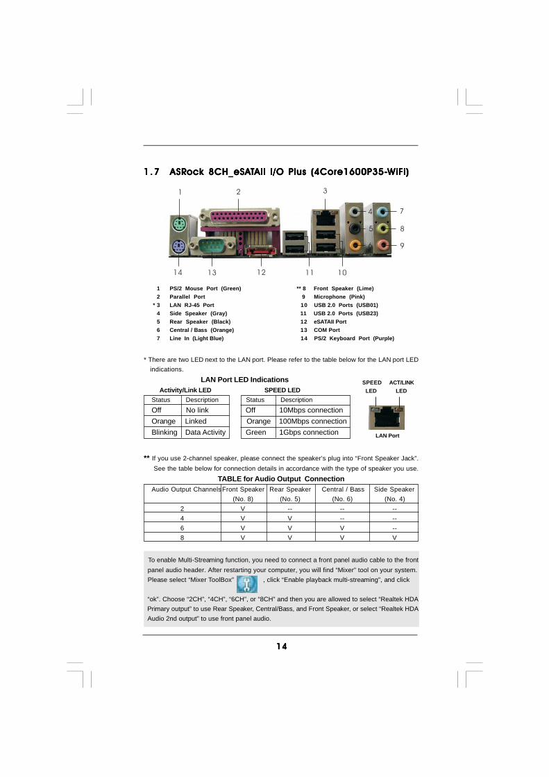
1 .71 .71 .71 .71 .7 ASRASRASRASRASRock 8CH_eSAock 8CH_eSAock 8CH_eSAock 8CH_eSAock 8CH_eSATTTTTAII I/O Plus (4Core1600P35-AII I/O Plus (4Core1600P35-AII I/O Plus (4Core1600P35-AII I/O Plus (4Core1600P35-AII I/O Plus (4Core1600P35-WWWWWiFiFiFiFiFi)i)i)i)i)
1 PS/2 Mouse Port (Green) ** 8 Front Speaker (Lime)2 Parallel Port 9 Microphone (Pink)
* 3 LAN RJ-45 Port 10 USB 2.0 Ports (USB01)4 Side Speaker (Gray) 11 USB 2.0 Ports (USB23)5 Rear Speaker (Black) 12 eSATAII Port6 Central / Bass (Orange) 13 COM Port7 Line In (Light Blue) 14 PS/2 Keyboard Port (Purple)
To enable Multi-Streaming function, you need to connect a front panel audio cable to the front panel audio header. After restarting your computer, you will find “Mixer” tool on your system. Please select “Mixer ToolBox” , click “Enable playback multi-streaming”, and click
“ok”. Choose “2CH”, “4CH”, “6CH”, or “8CH” and then you are allowed to select “Realtek HDA Primary output” to use Rear Speaker, Central/Bass, and Front Speaker, or select “Realtek HDA Audio 2nd output” to use front panel audio.
6
7
1 2
4
3
5 8
9
1011121314
** If you use 2-channel speaker, please connect the speaker’s plug into “Front Speaker Jack”. See the table below for connection details in accordance with the type of speaker you use.
TABLE for Audio Output ConnectionAudio Output ChannelsFront Speaker Rear Speaker Central / Bass Side Speaker
(No. 8) (No. 5) (No. 6) (No. 4)2 V -- -- --4 V V -- --6 V V V --8 V V V V
* There are two LED next to the LAN port. Please refer to the table below for the LAN port LED indications.
LAN Port LED Indications Activity/Link LED SPEED LEDStatus Description Status DescriptionOff No link Off 10Mbps connectionOrange Linked Orange 100Mbps connectionBlinking Data Activity Green 1Gbps connection LAN Port
ACT/LINK LED
SPEED LED

1515151515
1 .81 .81 .81 .81 .8 ASRock WiFi-802.11g Module SpecificationsASRock WiFi-802.11g Module SpecificationsASRock WiFi-802.11g Module SpecificationsASRock WiFi-802.11g Module SpecificationsASRock WiFi-802.11g Module Specifications
ASRock WiFi-802.11g module is an easy-to-use wireless local area network (WLAN)adapter to support WiFi+AP function. With ASRock WiFi-802.11g module, you caneasily create a wireless environment and enjoy the convenience of wireless networkconnectivity. Therefore, from anywhere within the signal range, you will be able to playLAN games, connect to the internet, access and share printers, and make Internetphone calls easily.
Standard - IEEE 802.11g Data Rate - 6, 9, 12, 18, 24, 36, 48, 54Mbps Security - Access Point mode (AP mode): WEP, WPA Network - Access Point mode (AP mode) Architecture Types - Station mode: Infrastructure mode and Ad-Hoc mode Frequency Band - 2.4~2.5GHz Operating Range - Indoor: 80ft (30m)
Outdoor: 200ft (60m)* The range varies in different environments
Number of - up to 16 stations Connected Devices (AP Mode) Antenna - ASRock WiFi-802.11g omni-directional antenna LED - Green data transmission (AIR) LED Support OS - Windows® XP / XP 64-bit / VistaTM / VistaTM 64-bit Compatibility - Full compatible with IEEE 802.11g standard products Software Support - ASRock WiFi-802.11g Wizard
If you want to start to use ASRock WiFi-802.11g module on this motherboard, pleasecarefully read “ASRock WiFi-802.11g Module Operation Guide” in the package forthe detailed introduction and operation procedures. You can also read the document inthe following path of ASRock motherboard support CD:..\ ASRock WiFi-802.11g \ Vista64_Vista_XP64_XP

1616161616
Chapter 2: InstallationChapter 2: InstallationChapter 2: InstallationChapter 2: InstallationChapter 2: InstallationThis is an ATX form factor (12.0" x 9.6", 30.5 x 24.4 cm) motherboard. Before you installthe motherboard, study the configuration of your chassis to ensure that the motherboardfits into it.
Make sure to unplug the power cord before installing or removing themotherboard. Failure to do so may cause physical injuries to you anddamages to motherboard components.
2.1 Screw Holes2.1 Screw Holes2.1 Screw Holes2.1 Screw Holes2.1 Screw HolesPlace screws into the holes indicated by circles to secure the motherboard to thechassis.
Do not over-tighten the screws! Doing so may damage the motherboard.
2.2 Pre-installation Precautions2.2 Pre-installation Precautions2.2 Pre-installation Precautions2.2 Pre-installation Precautions2.2 Pre-installation PrecautionsTake note of the following precautions before you install motherboard componentsor change any motherboard settings.
1. Unplug the power cord from the wall socket before touching any component.2. To avoid damaging the motherboard components due to static electricity, NEVER
place your motherboard directly on the carpet or the like. Also remember to usea grounded wrist strap or touch a safety grounded object before you handlecomponents.
3. Hold components by the edges and do not touch the ICs.4. Whenever you uninstall any component, place it on a grounded antistatic pad or
in the bag that comes with the component.
Before you install or remove any component, ensure that the power is switched off or the power cord is detached from the power supply. Failure to do so may cause severe damage to the motherboard, peripherals, and/or components.

1717171717
2.3 CPU Installation2.3 CPU Installation2.3 CPU Installation2.3 CPU Installation2.3 CPU InstallationFor the installation of Intel 775-LAND CPU,please follow the steps below.
Before you insert the 775-LAND CPU into the socket, please check ifthe CPU surface is unclean or if there is any bent pin on the socket.Do not force to insert the CPU into the socket if above situation isfound. Otherwise, the CPU will be seriously damaged.
Step 1. Open the socket:Step 1-1. Disengaging the lever by depressing
down and out on the hook to clearretention tab.
Step 1-2. Rotate the load lever to fully open po-sition at approximately 135 degrees.
Step 1-3. Rotate the load plate to fully open po-sition at approximately 100 degrees.
Step 2. Insert the 775-LAND CPU:Step 2-1. Hold the CPU by the edges where are
marked with black lines.
Step 2-2. Orient the CPU with IHS (IntegratedHeat Sink) up. Locate Pin1 and the twoorientation key notches.
775-Pin Socket Overview
black line
black line
775-Pin Socket
Pin1alignment key alignment key
Pin1
orientationkey notch
orientationkey notch
775-LAND CPU

1818181818
For proper inserting, please ensure to match the two orientation keynotches of the CPU with the two alignment keys of the socket.
Step 2-3. Carefully place the CPU into the socketby using a purely vertical motion.
Step 2-4. Verify that the CPU is within the socketand properly mated to the orient keys.
Step 3. Remove PnP Cap (Pick and Place Cap):Use your left hand index finger and thumb tosupport the load plate edge, engage PnP capwith right hand thumb and peel the cap from thesocket while pressing on center of PnP cap toassist in removal.
1. It is recommended to use the cap tab to handle and avoid kicking off the PnP cap.2. This cap must be placed if returning the motherboard for after service.
Step 4. Close the socket:Step 4-1. Rotate the load plate onto the IHS.Step 4-2. While pressing down lightly on load
plate, engage the load lever.Step 4-3. Secure load lever with load plate tab
under retention tab of load lever.
1919191919
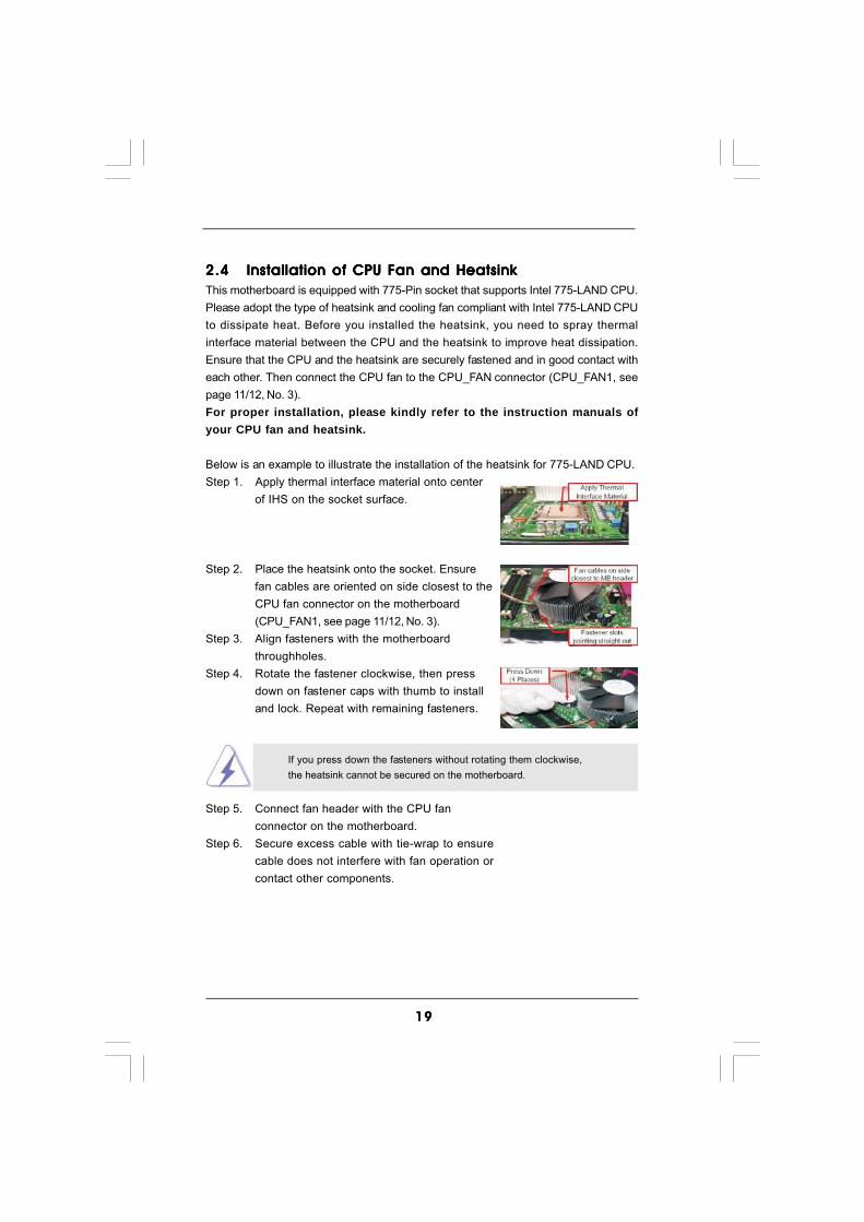
2.42.42.42.42.4 Installation of CPU Fan and HeatsinkInstallation of CPU Fan and HeatsinkInstallation of CPU Fan and HeatsinkInstallation of CPU Fan and HeatsinkInstallation of CPU Fan and HeatsinkThis motherboard is equipped with 775-Pin socket that supports Intel 775-LAND CPU.Please adopt the type of heatsink and cooling fan compliant with Intel 775-LAND CPUto dissipate heat. Before you installed the heatsink, you need to spray thermalinterface material between the CPU and the heatsink to improve heat dissipation.Ensure that the CPU and the heatsink are securely fastened and in good contact witheach other. Then connect the CPU fan to the CPU_FAN connector (CPU_FAN1, seepage 11/12, No. 3).For proper installation, please kindly refer to the instruction manuals ofyour CPU fan and heatsink.
Below is an example to illustrate the installation of the heatsink for 775-LAND CPU.Step 1. Apply thermal interface material onto center
of IHS on the socket surface.
Step 2. Place the heatsink onto the socket. Ensurefan cables are oriented on side closest to theCPU fan connector on the motherboard(CPU_FAN1, see page 11/12, No. 3).
Step 3. Align fasteners with the motherboardthroughholes.
Step 4. Rotate the fastener clockwise, then pressdown on fastener caps with thumb to installand lock. Repeat with remaining fasteners.
If you press down the fasteners without rotating them clockwise,the heatsink cannot be secured on the motherboard.
Step 5. Connect fan header with the CPU fanconnector on the motherboard.
Step 6. Secure excess cable with tie-wrap to ensurecable does not interfere with fan operation orcontact other components.

2020202020
2.5 Installation of Memor2.5 Installation of Memor2.5 Installation of Memor2.5 Installation of Memor2.5 Installation of Memory Modules (DIMM)y Modules (DIMM)y Modules (DIMM)y Modules (DIMM)y Modules (DIMM)This motherboard provides four 240-pin DDR2 (Double Data Rate 2) DIMM slots andtwo 240-pin DDR3 (Double Data Rate 3) DIMM slots, and supports Dual ChannelMemory Technology. For dual channel configuration, you always need to installidentical (the same brand, speed, size and chip-type) DDR2/DDR3 DIMM pair inthe slots of the same color. In other words, you have to install identical DDR2DIMM pair in Dual Channel A (DDRII_1 and DDRII_3; Yellow slots; see p.11/12 No.6), identical DDR2 DIMM pair in Dual Channel B (DDRII_2 and DDRII_4; Orangeslots; see p.11/12 No.7), or identical DDR3 DIMM pair in Dual Channel C (DDR3_A1and DDR3_B1; Green slots; see p.11/12 No.8), so that Dual Channel Memory Tech-nology can be activated. This motherboard also allows you to install four DDR2DIMMs for dual channel configuration, and please install identical DDR2 DIMMs inall four slots. You may refer to the Dual Channel Memory Configuration Table below.
Dual Channel DDR2 Memory Configurations(DS: Double Side, SS: Single Side)
DDRII_1 DDRII_2 DDRII_3 DDRII_4 (Yellow Slot) (Orange Slot) (Yellow Slot) (Orange Slot)
2 memory modules SS X SS X2 memory modules DS X DS X2 memory modules X SS X SS2 memory modules X DS X DS4 memory modules SS SS SS SS4 memory modules DS DS DS DS
DDR3_A1 DDR3_B1 (Green Slot) (Green Slot)
2 memory modules SS SS2 memory modules DS DS
Dual Channel DDR3 Memory Configurations(DS: Double Side, SS: Single Side)

2121212121
1. If you want to install two memory modules, for optimal compatibil-ity and reliability, it is recommended to install them in the slots ofthe same color. In other words, install them in the set of greenslots (DDR3_A1 and DDR3_B1), in the set of yellow slots (DDRII_1and DDRII_3), or in the set of orange slots (DDRII_2 and DDRII_4).
2. If only one memory module or three memory modules are installedin the DDR2 DIMM slots on this motherboard, it is unable to acti-vate the Dual Channel Memory Technology. If only one memorymodule is installed in the DDR3 DIMM slots on this motherboard,it is unable to activate the Dual Channel Memory Technology.
3. If a pair of memory modules is NOT installed in the same DualChannel, for example, installing a pair of memory modules in DDRII_1and DDRII_2, it is unable to activate the Dual Channel MemoryTechnology .
4. It is not allowed to install a DDR3 memory module into DDR2 slotor install a DDR2 memory module into DDR3 slot; otherwise, thismotherboard and DIMM may be damaged.
5. DDR2 and DDR3 memory modules cannot be installed on thismotherboard at the same time.

2222222222
notch
break
Installing a DIMMInstalling a DIMMInstalling a DIMMInstalling a DIMMInstalling a DIMM
Please make sure to disconnect power supply before adding orremoving DIMMs or the system components.
Step 1. Unlock a DIMM slot by pressing the retaining clips outward.Step 2. Align a DIMM on the slot such that the notch on the DIMM matches the break
on the slot.
The DIMM only fits in one correct orientation. It will cause permanentdamage to the motherboard and the DIMM if you force the DIMM into the slotat incorrect orientation.
Step 3. Firmly insert the DIMM into the slot until the retaining clips at both ends fullysnap back in place and the DIMM is properly seated.
notch
break

2323232323
2.6 Expansion Slots (PCI, PCI Express, and AGI Express2.6 Expansion Slots (PCI, PCI Express, and AGI Express2.6 Expansion Slots (PCI, PCI Express, and AGI Express2.6 Expansion Slots (PCI, PCI Express, and AGI Express2.6 Expansion Slots (PCI, PCI Express, and AGI Express
Slots) Slots) Slots) Slots) Slots)There are 3 PCI slots, 1 PCI Express slot, and 1 AGI Express slot (PCI Express x4) onthis motherboard.PCI slots: PCI slots are used to install expansion cards that have the 32-bit PCI
interface.PCIE slots: PCIE1 (PCIE x16 slot) is used for PCI Express cards with x16 lane
width graphics cards.AGI Express slot (PCI Express x4):
AGI Express slot (PCI Express x4) is used to install PCI Express expan-sion cards.
If you plan to install only one PCI Express card on this motherboard, pleaseinstall it on PCIE1 (PCIE x16 slot).
Installing an expansion cardInstalling an expansion cardInstalling an expansion cardInstalling an expansion cardInstalling an expansion cardStep 1. Before installing the expansion card, please make sure that the power
supply is switched off or the power cord is unplugged. Please read thedocumentation of the expansion card and make necessary hardwaresettings for the card before you start the installation.
Step 2. Remove the bracket facing the slot that you intend to use. Keep the screwsfor later use.
Step 3. Align the card connector with the slot and press firmly until the card iscompletely seated on the slot.
Step 4. Fasten the card to the chassis with screws.
2.7 CrossFire2.7 CrossFire2.7 CrossFire2.7 CrossFire2.7 CrossFireTMTMTMTMTM Operation Guide Operation Guide Operation Guide Operation Guide Operation GuideThis motherboard supports CrossFireTM feature. CrossFireTM technology offers themost advantageous means available of combining multiple high performanceGraphics Processing Units (GPU) in a single PC. Combining a range of differentoperating modes with intelligent software design and an innovative interconnectmechanism, CrossFireTM enables the highest possible level of performance andimage quality in any 3D application. Currently CrossFireTM feature is supported withWindows® XP with Service Pack 2 and VistaTM OS. Please check AMD website forATITM CrossFireTM driver updates.
2424242424
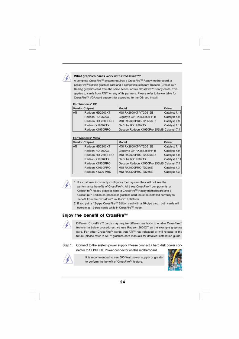
1. If a customer incorrectly configures their system they will not see the performance benefits of CrossFireTM. All three CrossFireTM components, a CrossFireTM Ready graphics card, a CrossFireTM Ready motherboard and a CrossFireTM Edition co-processor graphics card, must be installed correctly to benefit from the CrossFireTM multi-GPU platform.2. If you pair a 12-pipe CrossFireTM Edition card with a 16-pipe card, both cards will operate as 12-pipe cards while in CrossFireTM mode.
What graphics cards work with CrossFireTM?A complete CrossFireTM system requires a CrossFireTM Ready motherboard, aCrossFireTM Edition graphics card and a compatible standard Radeon (CrossFireTM
Ready) graphics card from the same series, or two CrossFireTM Ready cards. Thisapplies to cards from ATITM or any of its partners. Please refer to below table forCrossFireTM VGA card support list according to the OS you install.
Enjoy the benefit of CrossFireEnjoy the benefit of CrossFireEnjoy the benefit of CrossFireEnjoy the benefit of CrossFireEnjoy the benefit of CrossFireTMTMTMTMTM
Different CrossFireTM cards may require different methods to enable CrossFireTM
feature. In below procedures, we use Radeon 2600XT as the example graphicscard. For other CrossFireTM cards that ATITM has released or will release in thefuture, please refer to ATITM graphics card manuals for detailed installation guide.
It is recommended to use 500-Watt power supply or greaterto perform the benefit of CrossFireTM feature.
Step 1. Connect to the system power supply. Please connect a hard disk power con-nector to SLI/XFIRE Power connector on this motherboard.
For Windows® XPVendor Chipset Model DriverATI Radeon HD2900XT MSI RX2900XT-VT2D512E Catalyst 7.11
Radeon HD 2600XT Gigabyte GV-RX26T256HP-B Catalyst 7.9Radeon HD 2600PRO MSI RX2600PRO-T2D256EZ Catalyst 7.9Radeon X1950XTX GeCube RX1950XTX Catalyst 7.11Radeon X1950PRO Gecube Radeon X1950Pro 256MB Catalyst 7.11
For Windows® VistaVendor Chipset Model DriverATI Radeon HD2900XT MSI RX2900XT-VT2D512E Catalyst 7.11
Radeon HD 2600XT Gigabyte GV-RX26T256HP-B Catalyst 7.9Radeon HD 2600PRO MSI RX2600PRO-T2D256EZ Catalyst 7.9Radeon X1950XTX GeCube RX1950XTX Catalyst 7.11Radeon X1950PRO Gecube Radeon X1950Pro 256MB Catalyst 7.11Radeon X1600PRO MSI RX1600PRO-TD256E Catalyst 7.3Radeon X1300 PRO MSI RX1300PRO-TD256E Catalyst 7.3
2525252525
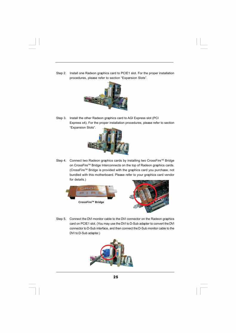
Step 2. Install one Radeon graphics card to PCIE1 slot. For the proper installationprocedures, please refer to section “Expansion Slots”.
Step 3. Install the other Radeon graphics card to AGI Express slot (PCIExpress x4). For the proper installation procedures, please refer to section“Expansion Slots”.
Step 4. Connect two Radeon graphics cards by installing two CrossFireTM Bridgeon CrossFireTM Bridge Interconnects on the top of Radeon graphics cards.(CrossFireTM Bridge is provided with the graphics card you purchase, notbundled with this motherboard. Please refer to your graphics card vendorfor details.)
Step 5. Connect the DVI monitor cable to the DVI connector on the Radeon graphicscard on PCIE1 slot. (You may use the DVI to D-Sub adapter to convert the DVIconnector to D-Sub interface, and then connect the D-Sub monitor cable to theDVI to D-Sub adapter.)
CrossFireTM Bridge
2626262626
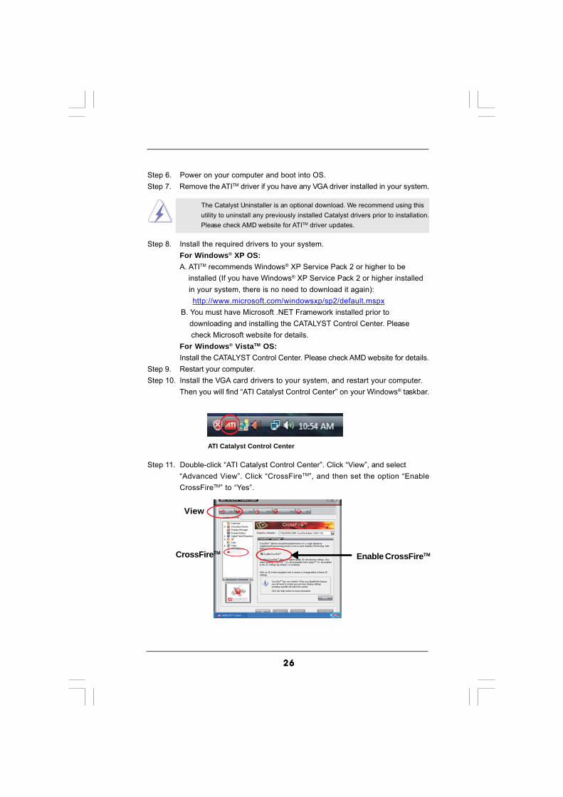
Step 6. Power on your computer and boot into OS.Step 7. Remove the ATITM driver if you have any VGA driver installed in your system.
The Catalyst Uninstaller is an optional download. We recommend using thisutility to uninstall any previously installed Catalyst drivers prior to installation.Please check AMD website for ATITM driver updates.
Step 8. Install the required drivers to your system.For Windows® XP OS:A. ATITM recommends Windows® XP Service Pack 2 or higher to be installed (If you have Windows® XP Service Pack 2 or higher installed in your system, there is no need to download it again):
http://www.microsoft.com/windowsxp/sp2/default.mspx B. You must have Microsoft .NET Framework installed prior to downloading and installing the CATALYST Control Center. Please check Microsoft website for details.
For Windows® VistaTM OS:Install the CATALYST Control Center. Please check AMD website for details.
Step 9. Restart your computer.Step 10. Install the VGA card drivers to your system, and restart your computer.
Then you will find “ATI Catalyst Control Center” on your Windows® taskbar.
ATI Catalyst Control Center
Step 11. Double-click “ATI Catalyst Control Center”. Click “View”, and select“Advanced View”. Click “CrossFireTM”, and then set the option “EnableCrossFireTM” to “Yes”.
View
CrossFireTM Enable CrossFireTM

2727272727
Although you have selected the option “Enable CrossFireTM”, the CrossFireTM
function may not work actually. Your computer will automatically reboot. Afterrestarting your computer, please confirm whether the option “Enable CrossFireTM”in “ATI Catalyst Control Center” is selected or not; if not, please select it again,and then you are able to enjoy the benefit of CrossFireTM feature.
Step 12. You can freely enjoy the benefit of CrossFireTM feature.
* CrossFireTM appearing here is a registered trademark of ATITM Technologies Inc., and is used only for identification or explanation and to the owners’ benefit, without intent to infringe.* For further information of ATITM CrossFireTM technology, please check AMD website for updates and details.
2.8 Surround Display Feature2.8 Surround Display Feature2.8 Surround Display Feature2.8 Surround Display Feature2.8 Surround Display FeatureThis motherboard supports Surround Display upgrade. With the external add-onPCI Express VGA card, you can easily enjoy the benefits of Surround Displayfeature. For the detailed instruction, please refer to the document at the followingpath in the Support CD:..\ Surround Display Information

2828282828
2.9 Jumpers Setup2.9 Jumpers Setup2.9 Jumpers Setup2.9 Jumpers Setup2.9 Jumpers SetupThe illustration shows how jumpers are setup.When the jumper cap is placed onpins, the jumper is “Short”. If no jumper cap isplaced on pins, the jumper is “Open”. The il-lustration shows a 3-pin jumper whose pin1and pin2 are “Short” when jumper cap isplaced on these 2 pins.Jumper Setting DescriptionPS2_USB_PWR1 Short pin2, pin3 to enable(see p.11/12 No. 1) +5VSB (standby) for PS/2
or USB wake up events.Note: To select +5VSB, it requires 2 Amp and higher standby current provided by
power supply.
Clear CMOS Jumper(CLRCMOS1)
(see p.11/12, No. 10)
Note: CLRCMOS1 allows you to clear the data in CMOS. The data in CMOS includessystem setup information such as system password, date, time, and systemsetup parameters. To clear and reset the system parameters to default setup,please turn off the computer and unplug the power cord from the power supply.After waiting for 15 seconds, use a jumper cap to short pin2 and pin3 on CLRCMOS1for 5 seconds. However, please do not clear the CMOS right after you update theBIOS. If you need to clear the CMOS when you just finish updating the BIOS, youmust boot up the system first, and then shut it down before you do the clear-CMOS action.
+5V
1_2
+5VSB
2_3
Clear CMOS
2_31_2
Default

2929292929
FSB1 Jumper(FSB1, 3-pin jumper, see p.11 No. 34 or p.12 No. 33)
FSB2 Jumper(FSB2, 5-pin jumper, see p.11 No. 35 or p.12 No. 34)
FSB3 Jumper(FSB3, 5-pin jumper, see p.11 No. 35 or p.12 No. 34)
Note1: If you use a FSB1600-CPU on this motherboard, you need to adjust the jumpers.Please short pin4, pin5 for FSB3. Otherwise, the CPU may not work properly onthis motherboard. Please refer to below jumper settings.
Note2: If you use a FSB1333-CPU and adopt a DDR2 1066 memory module on thismotherboard, you need to adjust the jumpers. Please short pin4, pin5 forFSB2. Otherwise, the CPU and memory module may not work properly onthis motherboard. Please refer to below jumper settings.
Note3: If you use a FSB1066-CPU and adopt a DDR2 1066 memory module on thismotherboard, you need to adjust the jumpers. Please short pin2, pin3 forFSB3. Otherwise, the CPU and memory module may not work properly onthis motherboard. Please refer to below jumper settings.
1_2
FSB2
1_2
FSB1
1_2
FSB3
4_5
FSB3
1_2
FSB1
FSB2
1_2
Default
FSB2
1_2
FSB1
1_2
FSB3
4_5
1_2
FSB2
1_2
FSB1
2_3
FSB3
FSB1600
FSB1333 / DDR2 1066
FSB1066 / DDR2 1066

3030303030
2.10 Onboard Headers and Connectors2.10 Onboard Headers and Connectors2.10 Onboard Headers and Connectors2.10 Onboard Headers and Connectors2.10 Onboard Headers and Connectors
Onboard headers and connectors are NOT jumpers. Do NOT placejumper caps over these headers and connectors. Placing jumper capsover the headers and connectors will cause permanent damage of themotherboard!
FDD connector(33-pin FLOPPY1)
(see p.11 No. 28 or p.12 No. 27)
Note: Make sure the red-striped side of the cable is plugged into Pin1 side of theconnector.
Primary IDE connector (Blue)(39-pin IDE1, see p.11/12 No. 9)
Note: Please refer to the instruction of your IDE device vendor for the details.
Serial ATAII Connectors These six Serial ATAII (SATAII)(SATAII_1 (Port0): connectors support SATA datasee p.11/12, No. 12) cables for internal storage(SATAII_2 (Port1): devices. The current SATAIIsee p.11/12, No. 14) interface allows up to 3.0 Gb/s(SATAII_3 (Port2): data transfer rate.see p.11/12, No. 17)(SATAII_4 (Port3):see p.11/12, No. 18)(SATAII_5 (Port4):see p.11/12, No. 11)(SATAII_6 (Port5):see p.11/12, No. 19)
SATAII_6 (Port5) connector can be used for internal storage device orbe connected to eSATAII connector to support eSATAII device. Pleaseread “eSATAII Interface Introduction” on page 37 for details abouteSATAII and eSATAII installation procedures.
FLOPPY1Pin1
the red-striped side to Pin1
connect the black endto the IDE devices
connect the blue endto the motherboard
IDE1PIN1
80-conductor ATA 66/100/133 cable
SATAII_5 (Port4) SATAII_1 (Port0)
SATAII_6 (Port5) SATAII_2 (Port1)
SATAII_3 (Port2)
SATAII_4 (Port3)

3131313131
eSATAII Connector This eSATAII connector(eSATAII: see p.11, No. 39 or p.12, No. 38) supports SATA data cable for
external SATAII function. Thecurrent eSATAII interfaceallows up to 3.0 Gb/s datatransfer rate.
Serial ATA (SATA) Either end of the SATA data cableData Cable can be connected to the SATA /(Optional) SATAII hard disk or the SATAII
connector on this motherboard.You can also use the SATA datacable to connect SATAII_6 (Port5)connector and eSATAIIconnector.
Serial ATA (SATA) Please connect the black end ofPower Cable SATA power cable to the power(Optional) connector on each drive. Then
connect the white end of SATApower cable to the powerconnector of the power supply.
eSATAII
connect to the SATA HDDpower connector
connect to thepower supply
USB_PWR
USB_PWR
P+5P-5
P+4P-4
GND
GND
DUMMY
1
USB_PWR
USB_PWR
P+7P-7
P+6P-6
GND
GND
DUMMY
1
1
USB_PWRP-8
GND
DUMMY
USB_PWR
P+8
GND
P-9P+9
USB 2.0 Headers Besides four default USB 2.0(9-pin USB8_9) ports on the I/O panel, there are(see p.11/12 No. 22) three USB 2.0 headers on this
motherboard. Each USB 2.0header can support two USB2.0 ports.
(9-pin USB6_7)(see p.11/12 No. 20)
(9-pin USB4_5)(see p.11/12 No. 21)

3232323232
1
IRTX+5VSB
Hotplug#
IRRXGND
DeskExpress Hot Plug Detection This header supports the HotHeader Plug detection function for(5-pin IR1) ASRock DeskExpress.(see p.11 No. 27 or p.12 No. 26)
CD
-L
GN
DG
ND
CD
-R
CD1
J_SENSE
OUT2_L
1
MIC_RETPRESENCE#
GND
OUT2_RMIC2_R
MIC2_L
OUT_RET
Internal Audio Connectors This connector allows you(4-pin CD1) to receive stereo audio input(CD1: see p.11 No. 31 or p.12 No. 30) from sound sources such as
a CD-ROM, DVD-ROM, TVtuner card, or MPEG card.
Front Panel Audio Header This is an interface for front(9-pin HD_AUDIO1) panel audio cable that allows(see p.11 No. 30 or p.12 No. 29) convenient connection and
control of audio devices.
WiFi Header This header supports WiFi+AP(11-pin WIFI) function with ASRock(see p.11 No. 26 or p.12 No. 25) WiFi-802.11g or WiFi-802.11n
module, an easy-to-use wirelesslocal area network (WLAN)adapter. It allows you to create awireless environment and enjoy theconvenience of wireless networkconnectivity.
1
USB+5V_1
NCNC
GND1PLTRST#
+3SVB
USB+5V_1D0-D0+
GND1 PME#
1. High Definition Audio supports Jack Sensing, but the panel wire on the chassis must support HDA to function correctly. Please follow the
instruction in our manual and chassis manual to install your system.2. If you use AC’97 audio panel, please install it to the front panel audio header as below: A. Connect Mic_IN (MIC) to MIC2_L. B. Connect Audio_R (RIN) to OUT2_R and Audio_L (LIN) to OUT2_L.
C. Connect Ground (GND) to Ground (GND). D. MIC_RET and OUT_RET are for HD audio panel only. You don’t need to connect them for AC’97 audio panel. E. Enter BIOS Setup Utility. Enter Advanced Settings, and then select
Chipset Configuration. Set the Front Panel Control option from [Auto] to [Enabled].

3333333333
GND
PWRBTN#PLED-
PLED+
DUMMYRESET#
GND
HDLED+HDLED-
1
+5V
DUMMYDUMMY
SPEAKER
1Chassis Speaker Header Please connect the chassis(4-pin SPEAKER 1) speaker to this header.(see p.11/12 No. 15)
Chassis Fan Connector Please connect a chassis fan(3-pin CHA_FAN1) cable to this connector and(see p.11/12 No. 13) match the black wire to the
ground pin.
CPU Fan Connector Please connect a CPU fan cable(4-pin CPU_FAN1) to this connector and match(see p.11/12 No. 3) the black wire to the ground pin.
GND
+12VCHA_FAN_SPEED
F. Enter Windows system. Click the icon on the lower right hand taskbar to enter Realtek HD Audio Manager. For Windows® 2000 / XP / XP 64-bit OS: Click “Audio I/O”, select “Connector Settings” , choose
“Disable front panel jack detection”, and save the change by clicking “OK”. For Windows® VistaTM / VistaTM 64-bit OS: Click the right-top “Folder” icon , choose “Disable front
panel jack detection”, and save the change by clicking “OK”.
4321GND
+12V
CPU_FAN_SPEED
FAN_SPEED_CONTROL
Though this motherboard provides 4-Pin CPU fan (Quiet Fan) support, the 3-Pin CPU fan still can work successfully even without the fan speed control function. If you plan to connect the 3-Pin CPU fan to the CPU fan connector on this motherboard, please connect it to Pin 1-3.
3-Pin Fan Installation
Pin 1-3 Connected
System Panel Header This header accommodates(9-pin PANEL1) several system front panel(see p.11/12 No. 16) functions.
3434343434
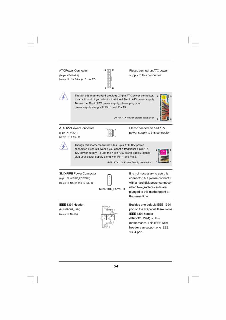
ATX 12V Power Connector Please connect an ATX 12V(8-pin ATX12V1) power supply to this connector.(see p.11/12 No. 2)
ATX Power Connector Please connect an ATX power(24-pin ATXPWR1) supply to this connector.(see p.11, No. 38 or p.12, No. 37)
12
1
24
13
20-Pin ATX Power Supply Installation
12
1
24
13
SLI/XFIRE Power Connector It is not necessary to use this(4-pin SLI/XFIRE_POWER1) connector, but please connect it(see p.11 No. 37 or p.12 No. 36) with a hard disk power connecor
when two graphics cards areplugged to this motherboard atthe same time.
SLI/XFIRE_POWER1
IEEE 1394 Header Besides one default IEEE 1394(9-pin FRONT_1394) port on the I/O panel, there is one(see p.11 No. 25) IEEE 1394 header
(FRONT_1394) on thismotherboard. This IEEE 1394header can support one IEEE1394 port.
+12V
GND+12V
1
RXTPBM_0GND
RXTPAM_0
RXTPBP_0GND
RXTPAP_0
4
1
8
5
4-Pin ATX 12V Power Supply Installation
4
1
8
5
Though this motherboard provides 24-pin ATX power connector,it can still work if you adopt a traditional 20-pin ATX power supply.To use the 20-pin ATX power supply, please plug yourpower supply along with Pin 1 and Pin 13.
Though this motherboard provides 8-pin ATX 12V powerconnector, it can still work if you adopt a traditional 4-pin ATX12V power supply. To use the 4-pin ATX power supply, pleaseplug your power supply along with Pin 1 and Pin 5.

3535353535
1
GND
+5VSPDIFOUT
HDMI_SPDIF Header HDMI_SPDIF header, providing(3-pin HDMI_SPDIF1) SPDIF audio output to HDMI VGA(see p.11 No. 29 or p.12 No. 28) card, allows the system to
connect HDMI Digital TV/projector/LCD devices. Pleaseconnect the HDMI_SPDIFconnector of HDMI VGA card tothis header.
HDMI_SPDIF Cable Please connect the black end (A)(Optional) of HDMI_SPDIF cable to the
HDMI_SPDIF header on themotherboard. Then connect thewhite end (B or C) ofHDMI_SPDIF cable to theHDMI_SPDIF connector of HDMIVGA card.
A. black end B. white end (2-pin) C. white end (3-pin)
CB
GND
+5V
SPDIFOUT blue
black
blue
blackGND
SPDIFOUT blue
blackGND
SPDIFOUT
A

3636363636
2.11 HDMI_SPDIF Header Connection Guide2.11 HDMI_SPDIF Header Connection Guide2.11 HDMI_SPDIF Header Connection Guide2.11 HDMI_SPDIF Header Connection Guide2.11 HDMI_SPDIF Header Connection GuideHDMI (High-Definition Multi-media Interface) is an all-digital audio/videospecification, which provides an interface between any compatible digital audio/video source, such as a set-top box, DVD player, A/V receiver and a compatibledigital audio or video monitor, such as a digital television (DTV). A complete HDMIsystem requires a HDMI VGA card and a HDMI ready motherboard with aHDMI_SPDIF header. This motherboard is equipped with a HDMI_SPDIF header,which provides SPDIF audio output to HDMI VGA card, allows the system toconnect HDMI Digital TV/projector/LCD devices. To use HDMI function on thismotherboard, please carefully follow the below steps.
•
Make sure to correctly connect the HDMI_SPDIF cable to the motherboard and theHDMI VGA card according to the same pin definition. For the pin definition ofHDMI_SPDIF header and HDMI_SPDIF cable connectors, please refer to page 35.For the pin definition of HDMI_SPDIF connectors on HDMI VGA card, please refer tothe user manual of HDMI VGA card vendor. Incorrect connection may causepermanent damage to this motherboard and the HDMI VGA card.
white end(2-pin) (B)
white end(3-pin) (C)
Please do not connect the white end of HDMI_SPDIF cable to the wrong connectorof HDMI VGA card or other VGA card. Otherwise, the motherboard and theVGA card may be damaged. For example, this picture shows the wrongexample of connecting HDMI_SPDIF cable to the fan connector of PCIExpress VGA card. Please refer to the VGA card user manual forconnector usage in advance.
Step 4. Connect the HDMI output connector on HDMI VGA card toHDMI device, such as HDTV. Please refer to the user manualof HDTV and HDMI VGA card vendor for detailed connectionprocedures.
Step 5. Install HDMI VGA card driver to your system.
Step 3. Connect the white end (B or C) of HDMI_SPDIF cable to the HDMI_SPDIFconnector of HDMI VGA card. (There are two white ends (2-pin and 3-pin)on HDMI_SPDIF cable. Please choose the appropriate white end accordingto the HDMI_SPDIF connector of the HDMI VGA card you install.
Step 1. Install the HDMI VGA card to the PCI Express Graphics slot on this motherboard. For the proper installation of HDMI VGA card, please refer to the installation guide on page 23.
Step 2. Connect the black end (A) of HDMI_SPDIF cable to theHDMI_SPDIF header (HDMI_SPDIF1, yellow, see page 11, No.29 or page 12, No. 28) on the motherboard.

3737373737
2.12 eSA2.12 eSA2.12 eSA2.12 eSA2.12 eSATTTTTAII InterAII InterAII InterAII InterAII Inter face Introductionface Introductionface Introductionface Introductionface Introduction
What is eSATAII?This motherboard supports eSATAII interface, the external SATAII specification.eSATAII allows you to enjoy the SATAII function provided by the I/O of yourcomputer, offering the high speed data transfer rate up to 3.0Gb/s, and theconvenient mobility like USB. eSATAII is equipped with Hot Plug capability thatenables you to exchange drives easily. For example, with eSATAII interface, youmay simply plug your eSATAII hard disk to the eSATAII ports instead of openingyour chassis to exchange your SATAII hard disk. Currently, on the market, thedata transfer rate of USB 2.0 is up to 480Mb/s, and for IEEE 1394 is up to400Mb/s. However, eSATAII provides the data transfer rate up to 3000Mb/s, which ismuch higher than USB 2.0 and IEEE 1394, and still keeps the convenience of HotPlug feature. Therefore, on the basis of the advantageous transfer speed and thefacilitating mobile capability, in the near future, eSATAII will replace USB 2.0 andIEEE 1394 to be a trend for external interface.
eSATAII connector(eSATAII)
NOTE:1. If you set “Configure SATAII as” option in BIOS setup to AHCI or RAID mode, Hot Plug function is supported with eSATAII devices. Therefore, you can insert or remove your eSATAII devices to the eSATAII ports while the system is power-on and in working condition.2. If you set “Configure SATAII as” option in BIOS setup to IDE mode, Hot Plug function is not supported with eSATAII devices. If you still want to use eSATAII function in IDE mode, please insert or remove your eSATAII devices to the eSATAII ports only when the system is power-off.3. Please refer to page 45 to 50 for detailed information of RAID mode, IDE mode, and AHCI mode.
How to install eSATAII?
SATAII connectorSATAII_6 (Port5)
3838383838
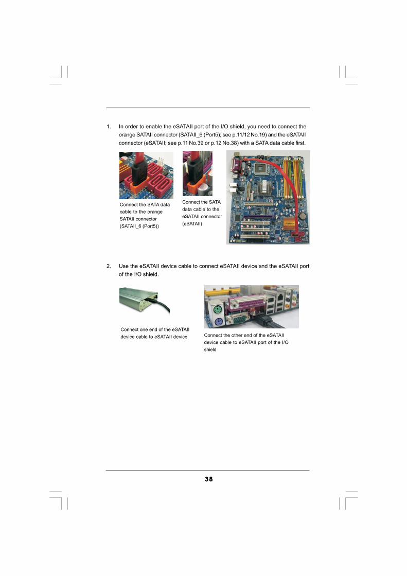
Connect one end of the eSATAIIdevice cable to eSATAII device Connect the other end of the eSATAII
device cable to eSATAII port of the I/Oshield
2. Use the eSATAII device cable to connect eSATAII device and the eSATAII portof the I/O shield.
Connect the SATA datacable to the orangeSATAII connector(SATAII_6 (Port5))
Connect the SATAdata cable to theeSATAII connector(eSATAII)
1. In order to enable the eSATAII port of the I/O shield, you need to connect theorange SATAII connector (SATAII_6 (Port5); see p.11/12 No.19) and the eSATAIIconnector (eSATAII; see p.11 No.39 or p.12 No.38) with a SATA data cable first.

3939393939
Comparison between eSATAII and other devices
IEEE 1394 400Mb/sUSB 2.0 480Mb/sSATA 1.5Gb/s (1500Mb/s)eSATAII/SATAII 3.0Gb/s (3000Mb/s)

4040404040
2.13 SA2.13 SA2.13 SA2.13 SA2.13 SATTTTTAII Hard Disk Setup GuideAII Hard Disk Setup GuideAII Hard Disk Setup GuideAII Hard Disk Setup GuideAII Hard Disk Setup GuideBefore installing SATAII hard disk to your computer, please carefully read belowSATAII hard disk setup guide. Some default setting of SATAII hard disks may not beat SATAII mode, which operate with the best performance. In order to enable SATAIIfunction, please follow the below instruction with different vendors to correctly adjustyour SATAII hard disk to SATAII mode in advance; otherwise, your
SATAII hard disk may fail to run at SATAII mode.
Western Digital
If pin 5 and pin 6 are shorted, SATA 1.5Gb/s will be enabled.On the other hand, if you want to enable SATAII 3.0Gb/s, please remove thejumpers from pin 5 and pin 6.
SAMSUNG
If pin 3 and pin 4 are shorted, SATA 1.5Gb/s will be enabled.On the other hand, if you want to enable SATAII 3.0Gb/s, please remove thejumpers from pin 3 and pin 4.
HITACHIPlease use the Feature Tool, a DOS-bootable tool, for changing various ATAfeatures. Please visit HITACHI’s website for details:http://www.hitachigst.com/hdd/support/download.htm
1357
2468
1357
2468
The above examples are just for your reference. For different SATAII hard disk products of different vendors, the jumper pin setting methods may
not be the same. Please visit the vendors’ website for the updates.

4141414141
2.142.142.142.142.14 Serial ASerial ASerial ASerial ASerial ATTTTTA (SAA (SAA (SAA (SAA (SATTTTTA) / Serial AA) / Serial AA) / Serial AA) / Serial AA) / Serial ATTTTTAII (SAAII (SAAII (SAAII (SAAII (SATTTTTAII) Hard DisksAII) Hard DisksAII) Hard DisksAII) Hard DisksAII) Hard Disks
InstallationInstallationInstallationInstallationInstallationThis motherboard adopts Intel® ICH9R south bridge chipset that supports Serial ATA(SATA) / Serial ATAII (SATAII) hard disks and RAID (RAID 0, RAID 1, RAID 10, RAID 5,and Intel Matrix Storage) functions. You may install SATA / SATAII hard disks on thismotherboard for internal storage devices. This section will guide you to install theSATA / SATAII hard disks.
STEP 1: Install the SATA / SATAII hard disks into the drive bays of your chassis.STEP 2: Connect the SATA power cable to the SATA / SATAII hard disk.STEP 3: Connect one end of the SATA data cable to the motherboard’s SATAII
connector.STEP 4: Connect the other end of the SATA data cable to the SATA / SATAII hard
disk.
1. If you plan to use RAID 0, RAID 1, RAID 10 or Intel Matrix Storage function, you need to install at least 2 SATA / SATAII hard disks. If you plan to use RAID 5 function, you need to install at least 3 SATA / SATAII hard disks.2. It is not recommended to switch the “Configure SATAII as” setting between AHCI, RAID and IDE mode after OS installation.
4242424242
2.15 Hot Plug and Hot Swap F2.15 Hot Plug and Hot Swap F2.15 Hot Plug and Hot Swap F2.15 Hot Plug and Hot Swap F2.15 Hot Plug and Hot Swap Functions for SAunctions for SAunctions for SAunctions for SAunctions for SATTTTTA / SAA / SAA / SAA / SAA / SATTTTTAIIAIIAIIAIIAII
HDDs and eSA HDDs and eSA HDDs and eSA HDDs and eSA HDDs and eSATTTTTAII DevicesAII DevicesAII DevicesAII DevicesAII DevicesThis motherboard supports Hot Plug and Hot Swap functions for SATA / SATAII /eSATAII Devices in RAID / AHCI mode. Intel® ICH9R south bridge chipset provideshardware support for Advanced Host controller Interface (AHCI), a new programminginterface for SATA host controllers developed thru a joint industry effort.
NOTEWhat is Hot Plug Function?If the SATA / SATAII HDDs are NOT set for RAID configuration, it is called“Hot Plug” for the action to insert and remove the SATA / SATAII HDDswhile the system is still power-on and in working condition.However, please note that it cannot perform Hot Plug if the OS has beeninstalled into the SATA / SATAII HDD.
What is Hot Swap Function?If SATA / SATAII HDDs are built as RAID1 or RAID 5 then it is called “HotSwap” for the action to insert and remove the SATA / SATAII HDDs whilethe system is still power-on and in working condition.
eSATAII is equipped with Hot Plug capability that enables you to exchangedrives easily. For example, with eSATAII interface, you may simply plug youreSATAII devices to the eSATAII ports instead of opening your chassis toexchange your SATAII hard disk.

4343434343
Caution1. Without SATA 15-pin power connector interface, the SATA / SATAII Hot Plug cannot be processed.2. Even some SATA / SATAII HDDs provide both SATA 15-pin power connector and IDE 1x4-pin conventional power connector interfaces, the IDE 1x4-pin conventional power connector interface is definitely not able to support Hot Plug and will cause the HDD damage and data loss.
SATA 7-pinconnector
1x4-pin conventionalpower connector (White)connect to power supply
A. SATA data cable (Red) B. SATA power cable
2.16 SA2.16 SA2.16 SA2.16 SA2.16 SATTTTTA / SAA / SAA / SAA / SAA / SATTTTTAII HDD Hot Plug FAII HDD Hot Plug FAII HDD Hot Plug FAII HDD Hot Plug FAII HDD Hot Plug Feature and Operationeature and Operationeature and Operationeature and Operationeature and Operation
GuideGuideGuideGuideGuideThis motherboard supports Hot Plug feature for SATA / SATAII HDD in RAID / AHCImode. Please read below operation guide of SATA / SATAII HDD Hot Plug featurecarefully. Before you process the SATA / SATAII HDD Hot Plug, please check belowcable accessories from the motherboard gift box pack.A. 7-pin SATA data cableB. SATA power cable with SATA 15-pin power connector interface
The SATA 15-pin powerconnector (Black) connectto SATA / SATAII HDD
Points of attention, before you process the Hot Plug:1. Below operation procedure is designed only for our motherboard, which supports SATA / SATAII HDD Hot Plug. * The SATA / SATAII Hot Plug feature might not be supported by the chipset because of its limitation, the SATA / SATAII Hot Plug support information of our motherboard is indicated in the product spec on our website: www.asrock.com2. Make sure your SATA / SATAII HDD can support Hot Plug function from your dealer or HDD user manual. The SATA / SATAII HDD, which cannot support Hot Plug function, will be damaged under the Hot Plug operation.3. Please make sure the SATA / SATAII driver is installed into system properly. The latest SATA / SATAII driver is available on our support website: www.asrock.com4. Make sure to use the SATA power cable & data cable, which are from our motherboard package.5. Please follow below instructions step by step to reduce the risk of HDD crash or data loss.

4444444444
How to Hot Plug a SATA / SATAII HDD:Points of attention, before you process the Hot Plug:Please do follow below instruction sequence to process the Hot Plug, improperprocedure will cause the SATA / SATAII HDD damage and data loss.
Connect SATA data cable tothe motherboard’s SATAII connector.
Connect SATA 15-pin power cable connector(Black) end to SATA / SATAII HDD.
Connect SATA data cable tothe SATA / SATAII HDD.
How to Hot Unplug a SATA / SATAII HDD:
Points of attention, before you process the Hot Unplug:Please do follow below instruction sequence to process the Hot Unplug, improperprocedure will cause the SATA / SATAII HDD damage and data loss.
Please connect SATA power cable 1x4-pin end(White) to the power supply 1x4-pin cable.
Step 1 Step 2
Step 3 Step 4
Step 2
SATA power cable 1x4-pinpower connector (White)
Unplug SATA data cable from SATA / SATAII HDD side.
Unplug SATA 15-pin power cable connector (Black) from SATA / SATAII HDD side.
Step 1

4545454545
2.172.172.172.172.17 Driver Installation Guide Driver Installation Guide Driver Installation Guide Driver Installation Guide Driver Installation GuideTo install the drivers to your system, please insert the support CD to your optical drivefirst. Then, the drivers compatible to your system can be auto-detected and listed onthe support CD driver page. Please follow the order from up to bottom side to installthose required drivers. Therefore, the drivers you install can work properly.
2.18.1 Installing Windows2.18.1 Installing Windows2.18.1 Installing Windows2.18.1 Installing Windows2.18.1 Installing Windows® XP / XP 64-bit With RAID XP / XP 64-bit With RAID XP / XP 64-bit With RAID XP / XP 64-bit With RAID XP / XP 64-bit With RAID
F F F F FunctionsunctionsunctionsunctionsunctionsIf you want to install Windows® XP / XP 64-bit on your SATA / SATAII HDDs with RAIDfunctions, please follow below steps.STEP 1: Set up BIOS.A. Enter BIOS SETUP UTILITY Advanced screen IDE Configuration.B. Set “SATAII Configuration” to [Enhanced], and then in the option “Configure SATAII as”, please set the option to [RAID].STEP 2: Make a SATA / SATAII Driver Diskette.A. Insert the Support CD into your optical drive to boot your system.B. During POST at the beginning of system boot-up, press <F11> key, and then a window for boot devices selection appears. Please select CD-ROM as the boot device.C. When you see the message on the screen, “Do you want to generate Serial ATA driver diskette [YN]?”, press <Y>.D. Then you will see these messages,
Please insert a diskette into the floppy drive.WARNING! Formatting the floppy diskette willlose ALL data in it!Start to format and copy files [YN]?Please insert a floppy diskette into the floppy drive, and press <Y>.
E. The system will start to format the floppy diskette and copy SATA / SATAII drivers into the floppy diskette.
2.182.182.182.182.18 Installing WindowsInstalling WindowsInstalling WindowsInstalling WindowsInstalling Windows® XP / XP 64-bit / Vista XP / XP 64-bit / Vista XP / XP 64-bit / Vista XP / XP 64-bit / Vista XP / XP 64-bit / VistaTM TM TM TM TM / Vista/ Vista/ Vista/ Vista/ VistaTMTMTMTMTM
64-bit W64-bit W64-bit W64-bit W64-bit With RAID Fith RAID Fith RAID Fith RAID Fith RAID FunctionsunctionsunctionsunctionsunctionsIf you want to install Windows® XP / XP 64-bit / VistaTM / VistaTM 64-bit OS on yourSATA / SATAII HDDs with RAID functions, please follow below procedures according tothe OS you install.
Since Windows® 2000 RAID / AHCI driver is not provided by the chipset vendor, RAID / AHCI functions are not supported under Windows® 2000.

4646464646
STEP 3: Use “RAID Installation Guide” to set RAID configuration.Before you start to configure the RAID function, you need to check the installationguide in the Support CD for proper configuration. Please refer to the document inthe Support CD, “Guide to SATA Hard Disks Installation and RAID Configuration”,which is located in the folder at the following path: .. \ RAID Installation GuideSTEP 4: Install Windows® XP / XP 64-bit OS on your system. (Windows® 2000 is not supported.)After making a SATA / SATAII driver diskette and using “RAID Installation Guide” to setRAID configuration, you can start to install Windows® XP / XP 64-bit on your system.At the beginning of Windows setup, press F6 to install a third-party RAID driver. Whenprompted, insert the SATA / SATAII driver diskette containing the Intel® RAID driver.After reading the floppy disk, the driver will be presented. Select the driver to installaccording to the mode you choose and the OS you install. You may select: "Intel(R)ICH8R/ICH9R SATA RAID Controller (Desktop - Windows XP)" for Windows® XP or"Intel(R) ICH8R/ICH9R SATA RAID Controller (Desktop - Windows XP64)" forWindows® XP 64-bit.
If you want to use “Intel Matrix Storage Manager” in Windows® environment, please install SATA / SATAII drivers from the Support CD again so that “Intel Matrix Storage Manager” will be installed to your system as well.
After the installation of Windows® XP / Windows® XP-64bit OS, if you want to manageRAID functions, you are allowed to use both “RAID Installation Guide” and “Intel MatrixStorage Manager Information” for RAID configuration. Please refer to the document in theSupport CD, “Guide to SATA Hard Disks Installation and RAID Configuration”, which islocated in the folder at the following path: .. \ RAID Installation Guide and the documentin the support CD, “Guide to Intel Matrix Storage Manager”, which is located in the folderat the following path: .. \ Intel Matrix Storage Manager Information
2.18.2 Setting Up a “RAID Ready” System2.18.2 Setting Up a “RAID Ready” System2.18.2 Setting Up a “RAID Ready” System2.18.2 Setting Up a “RAID Ready” System2.18.2 Setting Up a “RAID Ready” SystemYou can also set up a “RAID Ready” system with a single SATA / SATAII hard disk.A “RAID Ready” system can be seamlessly upgraded to RAID 0, RAID 1 or RAID 5at a later date by using RAID migration feature of Intel Matrix Storage. Thefollowing steps outline how to build an Intel “RAID Ready” system.
1. Assemble the system and attach a single SATA / SATAII hard drive.2. Set up system BIOS as step 1 of page 45. When done, exit Setup.3. Make a SATA / SATAII driver diskette as step 2 of page 45. Begin Windows®
setup by booting from the installation CD.4. At the beginning of Windows® setup, press F6 to install a third-party RAID driver. When prompted, insert the SATA / SATAII driver diskette containing the Intel® RAID driver. After reading the floppy disk, the driver will be presented.

4747474747
2.18.3 Migrating a “RAID Ready” System to RAID 0,2.18.3 Migrating a “RAID Ready” System to RAID 0,2.18.3 Migrating a “RAID Ready” System to RAID 0,2.18.3 Migrating a “RAID Ready” System to RAID 0,2.18.3 Migrating a “RAID Ready” System to RAID 0,
RAID 1 or RAID 5 RAID 1 or RAID 5 RAID 1 or RAID 5 RAID 1 or RAID 5 RAID 1 or RAID 5If you have an existing “RAID Ready” system, then you can use the followingsteps to perform a migration from a single non-RAID configuration to a two driveRAID 0, RAID 1 configuration or three drive RAID 5 configuration. To prepare forthis, you will need another SATA / SATAII hard drive with a capacity equal to orgreater than that currently being used as the source hard drive.
1. Physically attach one additional SATA / SATAII hard drive to the SATAII port not being used. Note the serial number of the hard drive already in the system; you will use this to select it as the source hard drive when initiating the migration.2. Boot Windows®, install the Intel(R) Matrix Storage Manager software, if not already installed, using the setup package obtained from a CD-ROM or from the Internet. This will install the necessary Intel Storage Utility and start menu links.3. Open the Intel Storage Utility from the Start Menu and select “Create RAID volume from Existing Hard Drive” from the Actions menu. This will activate the Create RAID volume from Existing Hard Drive Wizard. Click through the dialogs as prompted. It’s important to understand what will occur during the migration process because any data on the destination hard drive will be lost.4. Once the migration is complete, reboot the system. If you migrated to a RAID 0 volume, use Disk Management from within Windows® in order to partition and format the empty space created when the two hard drive capacities are combined. You may also use third-party software to extend any existing partitions within the RAID volume.
Select the driver to install according to the mode you choose and the OS you install. You may select: "Intel(R) ICH8R/ICH9R SATA RAID Controller (Desktop - Windows XP)" for Windows® XP or "Intel(R) ICH8R/ICH9R SATA RAID Controller (Desktop - Windows XP64)" for Windows® XP 64-bit.5. Finish the Windows® installation and install all necessary drivers.6. Install the Intel(R) Matrix Storage Manager software via the CD-ROM included with your motherboard or after downloading it from the Internet. This will add the Intel(R) Matrix Storage Console which can be used to manage the RAID configuration.7. After setting up a “RAID Ready” system as the above steps, you can follow the procedures of the next section to migrate the system to RAID 0, RAID 1 or RAID 5.

4848484848
2.18.4 Installing Windows2.18.4 Installing Windows2.18.4 Installing Windows2.18.4 Installing Windows2.18.4 Installing Windows® Vista Vista Vista Vista VistaTMTMTMTMTM / Vista / Vista / Vista / Vista / VistaTMTMTMTMTM 64-bit With 64-bit With 64-bit With 64-bit With 64-bit With
RAID F RAID F RAID F RAID F RAID FunctionsunctionsunctionsunctionsunctionsIf you want to install Windows® VistaTM / VistaTM 64-bit on your SATA / SATAII HDDswith RAID functions, please follow below steps.STEP 1: Set up BIOS.A. Enter BIOS SETUP UTILITY Advanced screen IDE Configuration.B. Set “SATAII Configuration” to [Enhanced], and then in the option “Configure SATAII as”, please set the option to [RAID].STEP 2: Use “RAID Installation Guide” to set RAID configuration.Before you start to configure the RAID function, you need to check the installationguide in the Support CD for proper configuration. Please refer to the document inthe Support CD, “Guide to SATA Hard Disks Installation and RAID Configuration”,which is located in the folder at the following path: .. \ RAID Installation GuideSTEP 3: Install Windows® VistaTM / VistaTM 64-bit OS on your system.Insert the Windows® VistaTM / VistaTM 64-bit optical disk into the optical drive to bootyour system, and follow the instruction to install Windows® VistaTM / VistaTM 64-bitOS on your system. When you see “Where do you want to install Windows?” page,please insert the ASRock Support CD into your optical drive, and click the “LoadDriver” button on the left on the bottom to load the Intel® RAID drivers. Intel® RAIDdrivers are in the following path in our Support CD:.. \ I386 (For Windows® VistaTM OS).. \ AMD64 (For Windows® VistaTM 64-bit OS)After that, please insert Windows® VistaTM / VistaTM 64-bit optical disk into the opticaldrive again to continue the installation.
After the installation of Windows® VistaTM / VistaTM 64-bit OS, if you want to manage RAIDfunctions, you are allowed to use both “RAID Installation Guide” and “Intel Matrix StorageManager Information” for RAID configuration. Please refer to the document in the SupportCD, “Guide to SATA Hard Disks Installation and RAID Configuration”, which is located in thefolder at the following path: .. \ RAID Installation Guide and the document in the supportCD, “Guide to Intel Matrix Storage Manager”, which is located in the folder at the followingpath: .. \ Intel Matrix Storage Manager Information
If you want to use “Intel Matrix Storage Manager” in Windows® environment,please install SATA / SATAII drivers from the Support CD again so that “IntelMatrix Storage Manager” will be installed to your system as well.

4949494949
STEP 1: Set Up BIOS.A. Enter BIOS SETUP UTILITY Advanced screen IDE Configuration.B. Set “SATAII Configuration” to [Enhanced], and then in the option “Configure SATAII as”, please set the option to [AHCI].STEP 2: Make a SATA / SATAII driver diskette.Please make a SATA / SATAII driver diskette by following section 2.18.1 step 2 onpage 45.STEP 3: Install Windows® XP / XP 64-bit OS on your system. (Windows® 2000 is not supported.)After making a SATA / SATAII driver diskette, you can start to install Windows® XP / XP64-bit on your system. At the beginning of Windows® setup, press F6 to install a third-party AHCI driver. When prompted, insert the SATA / SATAII driver diskette containingthe Intel® AHCI driver. After reading the floppy disk, the driver will be presented. Selectthe driver to install according to the mode you choose and the OS you install. You mayselect: "Intel(R) ICH9 SATA AHCI Controller (Desktop - Windows XP)" for Windows® XPor "Intel(R) ICH9 SATA AHCI Controller (Desktop - Windows XP64)" for Windows® XP 64-bit.
2.192.192.192.192.19 Installing WindowsInstalling WindowsInstalling WindowsInstalling WindowsInstalling Windows® 2000 / XP / XP 64-bit / Vista 2000 / XP / XP 64-bit / Vista 2000 / XP / XP 64-bit / Vista 2000 / XP / XP 64-bit / Vista 2000 / XP / XP 64-bit / VistaTM TM TM TM TM /////
VistaVistaVistaVistaVistaTMTMTMTMTM 64-bit Without RAID Functions 64-bit Without RAID Functions 64-bit Without RAID Functions 64-bit Without RAID Functions 64-bit Without RAID FunctionsIf you want to install Windows® 2000 / XP / XP 64-bit / VistaTM / VistaTM 64-bit OSon your SATA / SATAII HDDs without RAID functions, please follow belowprocedures according to the OS you install.
2.19.1 Installing Windows2.19.1 Installing Windows2.19.1 Installing Windows2.19.1 Installing Windows2.19.1 Installing Windows® 2000 / XP / XP 64-bit 2000 / XP / XP 64-bit 2000 / XP / XP 64-bit 2000 / XP / XP 64-bit 2000 / XP / XP 64-bit
W W W W Without RAID Fithout RAID Fithout RAID Fithout RAID Fithout RAID FunctionsunctionsunctionsunctionsunctionsIf you want to install Windows® 2000 / XP / XP 64-bit OS on your SATA / SATAII HDDswithout RAID functions, please follow below steps.
Using SATA / SATAII HDDs and eSATAII devices with NCQ function
STEP 1: Set up BIOS.A. Enter BIOS SETUP UTILITY Advanced screen IDE Configuration.B. Set “SATAII Configuration” to [Enhanced], and then in the option “Configure SATAII as”, please set the option to [IDE].STEP 2: Install Windows® 2000 / XP / XP 64-bit OS on your system.
Using SATA / SATAII HDDs and eSATAII devices without NCQ function
Since Windows® 2000 RAID / AHCI driver is not provided by the chipset vendor, RAID / AHCI functions are not supported under Windows® 2000.
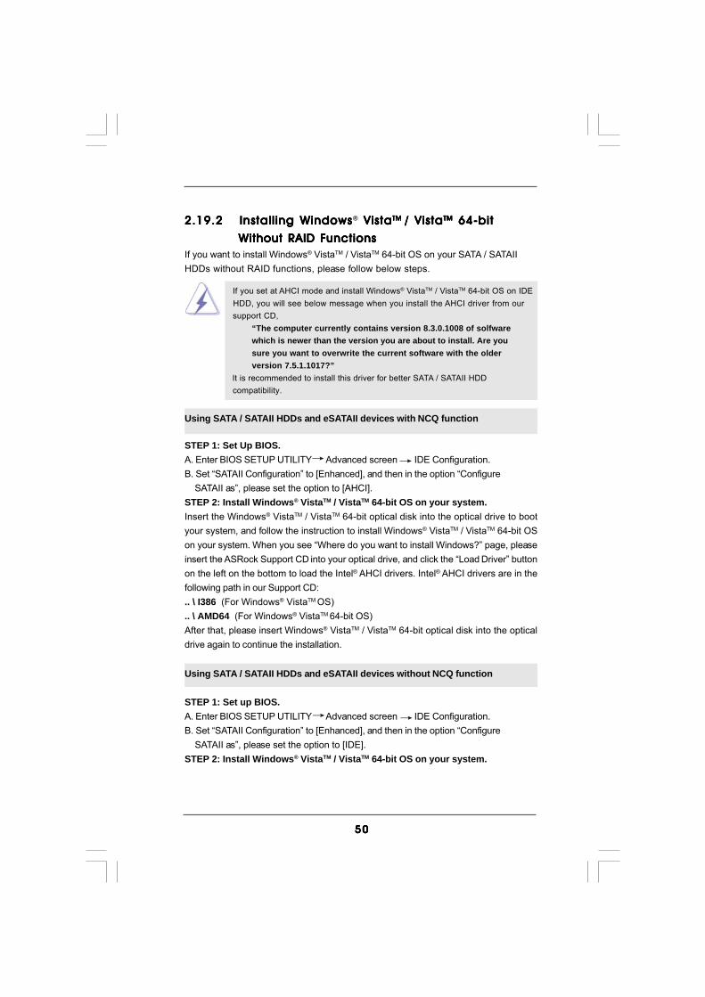
5050505050
2.19.2 Installing Windows2.19.2 Installing Windows2.19.2 Installing Windows2.19.2 Installing Windows2.19.2 Installing Windows® Vista Vista Vista Vista VistaTM TM TM TM TM / Vista/ Vista/ Vista/ Vista/ VistaTMTMTMTMTM 64-bit 64-bit 64-bit 64-bit 64-bit
W W W W Without RAID Fithout RAID Fithout RAID Fithout RAID Fithout RAID FunctionsunctionsunctionsunctionsunctionsIf you want to install Windows® VistaTM / VistaTM 64-bit OS on your SATA / SATAIIHDDs without RAID functions, please follow below steps.
Using SATA / SATAII HDDs and eSATAII devices with NCQ function
STEP 1: Set Up BIOS.A. Enter BIOS SETUP UTILITY Advanced screen IDE Configuration.B. Set “SATAII Configuration” to [Enhanced], and then in the option “Configure SATAII as”, please set the option to [AHCI].STEP 2: Install Windows® VistaTM / VistaTM 64-bit OS on your system.Insert the Windows® VistaTM / VistaTM 64-bit optical disk into the optical drive to bootyour system, and follow the instruction to install Windows® VistaTM / VistaTM 64-bit OSon your system. When you see “Where do you want to install Windows?” page, pleaseinsert the ASRock Support CD into your optical drive, and click the “Load Driver” buttonon the left on the bottom to load the Intel® AHCI drivers. Intel® AHCI drivers are in thefollowing path in our Support CD:.. \ I386 (For Windows® VistaTM OS).. \ AMD64 (For Windows® VistaTM 64-bit OS)After that, please insert Windows® VistaTM / VistaTM 64-bit optical disk into the opticaldrive again to continue the installation.
Using SATA / SATAII HDDs and eSATAII devices without NCQ function
STEP 1: Set up BIOS.A. Enter BIOS SETUP UTILITY Advanced screen IDE Configuration.B. Set “SATAII Configuration” to [Enhanced], and then in the option “Configure SATAII as”, please set the option to [IDE].STEP 2: Install Windows® VistaTM / VistaTM 64-bit OS on your system.
If you set at AHCI mode and install Windows® VistaTM / VistaTM 64-bit OS on IDE HDD, you will see below message when you install the AHCI driver from our support CD,
“The computer currently contains version 8.3.0.1008 of solfwarewhich is newer than the version you are about to install. Are yousure you want to overwrite the current software with the olderversion 7.5.1.1017?”
It is recommended to install this driver for better SATA / SATAII HDD compatibility.

5151515151
2.202.202.202.202.20 DTS Operation GuideDTS Operation GuideDTS Operation GuideDTS Operation GuideDTS Operation GuideDTS (Digital Theater Systems) is a multi-channel digital surround sound format tobring you a new class of entertainment experience by using home PCs. DTS makesaudio tracks more closely match the original master recording than other digitallyencoded soundtracks. Coupled with the multi-dimensional benefit of surround soundtechnology, the audio quality of DTS-format soundtracks and music mixesdramatically improves content.
Please follow below steps to enable DTS function:1. Install the drivers to your system from ASRock support CD.2. Reboot your system.
3. You will find the icon (Realtek HD Audio Manager) on the Windows® task bar.4. Double-click this icon to open Realtek HD Audio Manager.5. On the bottom of Realtek HD Audio Manager. You can find that the DTS Connect contains 2 elements: DTS Neo: PC and DTS Interactive. Click the button to enable or disable it.
DTS Neo: PC DTS Interactive
DTS Neo: PCDTS Neo: PC turns your stereo audio (WMA, MP3, CD and more) into aconvincing 7.1-channel audio experience.
DTS InteractiveDTS Interactive provides a single cable connection to your DTS enabledsurround sound system. Your stereo or multi-channel (up to 5.1) audiosources are re-encoded into a DTS audio signal and sent out from your PC toany DTS enabled system such as, powered PC speakers, an A/V receiver orany other DTS compatible surround sound system.
6. If you select DTS Neo: PC. You can click the icon (Detail Settings) to access advanced controls.
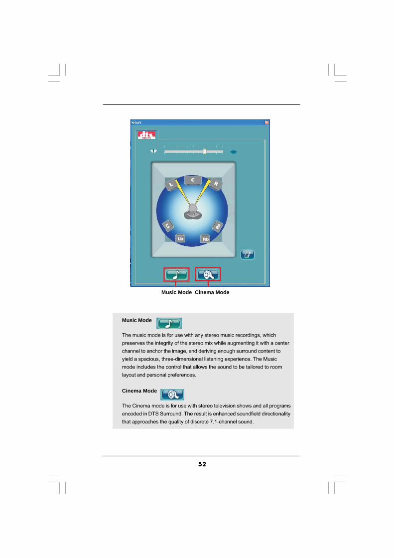
5252525252
Music Mode
The music mode is for use with any stereo music recordings, whichpreserves the integrity of the stereo mix while augmenting it with a centerchannel to anchor the image, and deriving enough surround content toyield a spacious, three-dimensional listening experience. The Musicmode includes the control that allows the sound to be tailored to roomlayout and personal preferences.
Cinema Mode
The Cinema mode is for use with stereo television shows and all programsencoded in DTS Surround. The result is enhanced soundfield directionalitythat approaches the quality of discrete 7.1-channel sound.
Music Mode Cinema Mode

5353535353
2.212.212.212.212.21 Untied Overclocking TUntied Overclocking TUntied Overclocking TUntied Overclocking TUntied Overclocking TechnologyechnologyechnologyechnologyechnologyThis motherboard supports Untied Overclocking Technology, which means duringoverclocking, FSB enjoys better margin due to fixed PCI / PCIE buses. Before youenable Untied Overclocking function, please enter “Overclock Mode” option ofBIOS setup to set the selection from [Auto] to [Manual]. Therefore, CPU FSB isuntied during overclocking, but PCI / PCIE buses are in the fixed mode so that FSBcan operate under a more stable overclocking environment.
Please refer to the warning on page 8 for the possible overclocking riskbefore you apply Untied Overclocking Technology.

5454545454
Chapter 3: BIOS SETUP UTILITYChapter 3: BIOS SETUP UTILITYChapter 3: BIOS SETUP UTILITYChapter 3: BIOS SETUP UTILITYChapter 3: BIOS SETUP UTILITY3.13 .13 .13 .13 .1 IntroductionIntroductionIntroductionIntroductionIntroductionThis section explains how to use the BIOS SETUP UTILITY to configure your system.The BIOS FWH chip on the motherboard stores the BIOS SETUP UTILITY. You mayrun the BIOS SETUP UTILITY when you start up the computer. Please press <F2>during the Power-On-Self-Test (POST) to enter the BIOS SETUP UTILITY, otherwise,POST will continue with its test routines.If you wish to enter the BIOS SETUP UTILITY after POST, restart the system bypressing <Ctl> + <Alt> + <Delete>, or by pressing the reset button on the systemchassis. You may also restart by turning the system off and then back on.
Because the BIOS software is constantly being updated, thefollowing BIOS setup screens and descriptions are for refer-ence purpose only, and they may not exactly match what yousee on your screen.
3.1.13.1.13.1.13.1.13.1.1 BIOS Menu BarBIOS Menu BarBIOS Menu BarBIOS Menu BarBIOS Menu BarThe top of the screen has a menu bar with the following selections:Main To set up the system time/date informationAdvanced To set up the advanced BIOS featuresH/W Monitor To display current hardware statusBoot To set up the default system device to locate and load the
Operating SystemSecurity To set up the security featuresExit To exit the current screen or the BIOS SETUP UTILITYUse < > key or < > key to choose among the selections on the menu bar,and then press <Enter> to get into the sub screen.

5555555555
3.1.23.1.23.1.23.1.23.1.2 Navigation KeysNavigation KeysNavigation KeysNavigation KeysNavigation KeysPlease check the following table for the function description of each navigationkey.
Navigation Key(s) Function Description / Moves cursor left or right to select Screens / Moves cursor up or down to select items + / - To change option for the selected items<Enter> To bring up the selected screen<F1> To display the General Help Screen<F9> To load optimal default values for all the settings<F10> To save changes and exit the BIOS SETUP UTILITY<ESC> To jump to the Exit Screen or exit the current screen
3.23.23.23.23.2 Main ScreenMain ScreenMain ScreenMain ScreenMain ScreenWhen you enter the BIOS SETUP UTILITY, the Main screen will appear and displaythe system overview.
4Core1600P35-WiFi
BIOS SETUP UTILITY
Main Advanced H/W Monitor Boot Security Exit
System Overview
System Time
System Date[ :00:09][Mon 12/03/2007]
Use [Enter], [TAB]or [SHIFT-TAB] toselect a field.
Use [+] or [-] toconfigure system Time.
Select ScreenSelect Item
+- Change FieldTab Select FieldF1 General HelpF9 Load DefaultsF10 Save and ExitESC Exit
BIOS VersionProcessor Type
Processor SpeedMicrocode Update
Total Memory
Cache Size
DDRII 1DDRII 2DDRII 3DDRII 4DDR3_1DDR3_2
: 4Core1600P35-WiFi P1.00: Intel (R) Core(TM)2 Extreme CPU
X9770 @ 3.20GHz (64bit): 3200MHz
: 12288KB: 10676/606
: 1024MB: 1024MB/400MHz (DDR2 800): None
: None: None
: 1024MB/400MHz (DDR2 800)
: None
v02.54 (C) Copyright 1985-2005, American Megatrends, Inc.
14

5656565656
BIOS SETUP UTILITY
Main H/W Monitor Boot Security Exit
Advanced Settings
WARNING : Setting wrong values in below sectionsmay cause system to malfunction.
Configure CPU
Select ScreenSelect Item
Enter Go to Sub ScreenF1 General HelpF9 Load DefaultsF10 Save and ExitESC Exit
v02.54 (C) Copyright 1985-2005, American Megatrends, Inc.
Advanced
CPU ConfigurationChipset Configuration
IDE ConfigurationPCIPnP ConfigurationFloppy ConfigurationSuperIO ConfigurationUSB Configuration
ACPI Configuration
3.33 .33 .33 .33 .3 Advanced ScreenAdvanced ScreenAdvanced ScreenAdvanced ScreenAdvanced ScreenIn this section, you may set the configurations for the following items: CPU Configuration,Chipset Configuration, ACPI Configuration, IDE Configuration, PCIPnP Configuration,Floppy Configuration, SuperIO Configuration, and USB Configuration.
4Core1600P35-WiFi+
BIOS SETUP UTILITY
Main Advanced H/W Monitor Boot Security Exit
System Overview
System Time
System Date[ :00:09][Mon 12/03/2007]
Use [Enter], [TAB]or [SHIFT-TAB] toselect a field.
Use [+] or [-] toconfigure system Time.
Select ScreenSelect Item
+- Change FieldTab Select FieldF1 General HelpF9 Load DefaultsF10 Save and ExitESC Exit
BIOS VersionProcessor Type
Processor SpeedMicrocode Update
Total Memory
Cache Size
DDRII 1DDRII 2DDRII 3DDRII 4DDR3_1DDR3_2
: 4Core1600P35-WiFi+ P1.00: Intel (R) Core(TM)2 Extreme CPU
X9770 @ 3.20GHz (64bit): 3200MHz
: 12288KB: 10676/606
: 1024MB: 1024MB/400MHz (DDR2 800): None: 1024MB/400MHz (DDR2 800): None: None: None
v02.54 (C) Copyright 1985-2005, American Megatrends, Inc.
14
System Time [Hour:Minute:Second]Use this item to specify the system time.
System Date [Day Month/Date/Year]Use this item to specify the system date.
Setting wrong values in this section may causethe system to malfunction.

5757575757
3.3.13.3.13.3.13.3.13.3.1 CPU ConfigurationCPU ConfigurationCPU ConfigurationCPU ConfigurationCPU Configuration
Overclock ModeUse this to select Overclock Mode. Configuration options: [Auto], [Manual]and [I.O.T.]. The default value is [Auto]. If you select [Manual], UntiedOverclocking function is enabled. Please refer to page 53 for the details ofUntied Overclocking Technology. If you select [I.O.T.] (Intelligent OverclockingTechnology), you are allowed to adjust the CPU frequency and PCIE frequencyin the following two items. Therefore, the system will automatically enable theoverclocking function when your CPU is heavy loaded.
CPU Frequency (MHz)Use this option to adjust CPU frequency.
PCIE Frequency (MHz)Use this option to adjust PCIE frequency.
Boot Failure GuardEnable or disable the feature of Boot Failure Guard.
Spread SpectrumThis item should always be [Auto] for better system stability.
Ratio StatusThis is a read-only item, which displays whether the ratio status of thismotherboard is “Locked” or “Unlocked”. If it shows “Unlocked”, you will find anitem Ratio CMOS Setting appears to allow you changing the ratio value ofthis motherboard.
Ratio Actual ValueThis is a read-only item, which displays the ratio actual value of thismotherboard.
BIOS SETUP UTILITY
CPU Configuration
Select ScreenSelect Item
+- Change OptionF1 General HelpF9 Load DefaultsF10 Save and ExitESC Exit
v02.54 (C) Copyright 1985-2005, American Megatrends, Inc.
Advanced
Boot Failure GuardSpread Spectrum
[Enabled][Auto]
Select ScreenSelect Item
+- Change OptionF1 General HelpF9 Load DefaultsF10 Save and ExitESC Exit
Ratio Status Unlocked (Min:06, Max:Unlimited)Ratio Actual Value 8
Select the over clockmode.
CPU Frequency (MHz)PCIE Frequency (MHz)
Overclock Mode
[400][100]
[Auto]
Enhanced Halt StateIntel Virtualization tech.CPU Thermal ThrottlingNo-Excute Memory ProtectionHyper Threading TechnologyIntel (R) SpeedStep(tm) tech.
[Disabled][Enabled][Enabled][Disabled][Enabled][Auto]

5858585858
Enhance Halt StateAll processors support the Halt State (C1). The C1 state is supportedthrough the native processor instructions HLT and MWAIT and requires nohardware support from the chipset. In the C1 power state, the processormaintains the context of the system caches.
Intel (R) Virtualization tech.When this option is set to [Enabled], a VMM (Virtual Machine Architecture)can utilize the additional hardware capabilities provided by VanderpoolTechnology. This option will be hidden if the installed CPU does not supportIntel (R) Virtualization Technology.
CPU Thermal ThrottlingYou may select [Enabled] to enable P4 CPU internal thermal control mecha-nism to keep the CPU from overheated.
No-Excute Memory ProtectionNo-Execution (NX) Memory Protection Technology is an enhancement to theIA-32 Intel Architecture. An IA-32 processor with “No Execute (NX) MemoryProtection” can prevent data pages from being used by malicious software toexecute code. This option will be hidden if the current CPU does not supportNo-Excute Memory Protection.
Hyper Threading TechnologyTo enable this feature, it requires a computer system with an Intel Pentium® 4processor that supports Hyper-Threading technology and an operating systemthat includes optimization for this technology, such as Microsoft® Windows®
XP. Set to [Enabled] if using Microsoft® Windows® XP, or Linux kernel version2.4.18 or higher. This option will be hidden if the installed CPU does not sup-port Hyper-Threading technology.
Intel (R) SpeedStep(tm) tech.Intel (R) SpeedStep(tm) tech. is Intel’s new power saving technology. Proces-sor can switch between multiple frequency and voltage points to enable powersavings. The default value is [Auto]. Configuration options: [Auto], [Enabled]and [Disabled]. If you install Windows® XP and select [Auto], you need to setthe “Power Schemes” as “Portable/Laptop” to enable this function. If youinstall Windows® VistaTM and want to enable this function, please set this itemto [Enabled]. This item will be hidden if the current CPU does not support Intel(R) SpeedStep(tm) tech..
Please note that enabling this function may reduce CPU voltage and lead to systemstability or compatibility issue with some power supplies. Please set this item to[Disable] if above issue occurs.

5959595959
3.3.23.3.23.3.23.3.23.3.2 Chipset ConfigurationChipset ConfigurationChipset ConfigurationChipset ConfigurationChipset Configuration
Memory Remap FeatureUse this item to enable or disable memory remap feature. Configurationoptions: [Enabled] and [Disabled]. The default value is [Disabled].
DRAM FrequencyIf [Auto] is selected, the motherboard will detect the memory module(s)inserted and assigns appropriate frequency automatically. You may select[333MHz (DDR2 667)], [400MHz (DDR2 800)] or [533MHz (DDR2 1066)] forDDR2 memory modules, or select [400MHz (DDR3 800)], [533MHz (DDR31066)] or [667MHz (DDR3 1333)] for DDR3 memory modules. The configura-tion options depend on the CPU and memory module you adopt on thismotherboard. Please refer to page 9 for the CPU FSB frequency and its corre-sponding memory support frequency.
Flexibility OptionThe default value of this option is [Disabled]. It will allow better tolerance formemory compatibility when it is set to [Enabled].DRAM CAS# Latency
Use this item to adjust the means of memory accessing. Configurationoptions for DDR2 memory modules are [3], [4], [5], [6] and [Auto].Configuration options for DDR3 memory modules are are [5], [6], [7], [8],[9] and [Auto].
DRAM RAS# to CAS# DelayThis controls the latency between the DRAM active command and theread / write command. Configuration options: [Auto], [3 DRAM Clocks], [4DRAM Clocks], [5 DRAM Clocks] and [6 DRAM Clocks].
DRAM RAS# PrechargeThis controls the idle clocks after a precharge command is issued.
Configuration options: [Auto], [3 DRAM Clocks], [4 DRAM Clocks], [5 DRAM Clocks] and [6 DRAM Clocks].
BIOS SETUP UTILITY
v02.54 (C) Copyright 1985-2005, American Megatrends, Inc.
Chipset Configuration
Memory Remap Feature
DRAM FrequencyFlexibility Option
DRAM CAS# LatencyDRAM RAS# to CAS# DelayDRAM RAS# PrechargeDRAM RAS# Activate to Precha
[Auto][Disabled]
[Auto][Auto]
[Auto][Auto]
[Disabled]
Select ScreenSelect Item
+ - Change OptionF1 General Help
F10 Save and ExitESC Exit
F9 Load Defaults
ENABLE: Allowremapping ofoverlapped PCI memoryabove the totalphysical memory.
DISABLE: Do not allowremapping of memory.
Advanced
Primary Graphics Adapter [PCI]
OnBoard HD AudioFront Panel
OnBoard LanOnBoard 1394
[Auto][Auto][Enabled][Enabled]
CPU VoltageDRAM VoltageNB Core Voltage
[Auto][Auto]
[Auto]

6060606060
DRAM RAS# Activate to PrechargeThis controls the number of DRAM clocks for TRAS. Configuration options:Configuration options: [Auto], [9 DRAM Clocks], [10 DRAM Clocks], [11DRAM Clocks], [12 DRAM Clocks], [13 DRAM Clocks], [14 DRAM Clocks]and [15 DRAM Clocks].
Primary Graphics AdapterThis allows you to select [PCI] or [PCI Express] as the boot graphic adapterpriority. The default value is [PCI].
OnBoard HD AudioSelect [Auto], [Enabled] or [Disabled] for the onboard HD Audio feature. If youselect [Auto], the onboard HD Audio will be disabled when PCI Sound Card isplugged.
Front PanelSelect [Auto], [Enabled] or [Disabled] for the onboard HD Audio Front Panel.
OnBoard LanThis allows you to enable or disable the “OnBoard Lan” feature.
OnBoard 1394This allows you to enable or disable the “OnBoard 1394” feature.
CPU VoltageUse this to select CPU Voltage. Configuration options: [Auto] and [Manual].The default value of this feature is [Auto].
DRAM VoltageUse this to select DRAM Voltage. Configuration options for DDR2 memorymodules: [Auto], [1.79V], [1.85V], [1.90V], [1.96V], [2.02V], [2.08V], [2.14V],[2.20V], [2.31V], [2.37V], [2.42V], [2.48V], [2.54V], [2.60V], [2.66V] and[2.72V]. Configuration options for DDR3 memory modules: [Auto], [1.47V],[1.53V], [1.64V], [1.71V], [1.76V], [1.82V], [1.88V], [1.99V], [2.05V], [2.11V],[2.16V], [2.23V], [2.28V], [2.34V], [2.40V] and [2.66V]. The default value ofthis feature is [Auto].
NB Core VoltageUse this to select Northbridge Core Voltage. Configuration options: [Auto],[Low], [Middle], [High] and [Highest]. The default value of this feature is [Auto].
SB VoltageUse this to select Southbridge Voltage. Configuration options: [Auto], [Low],[Middle], [High] and [Highest]. The default value of this feature is [Auto].
VTT VoltageUse this to select VTT Voltage. Configuration options: [Auto], [Low],[Middle], [High] and [Highest]. The default value of this feature is [Auto].
DRAM RCOMP SettingUse this to adjust DRAM RCOMP Setting feature. Configuration options: [Auto]and [Manual]. The default value of this feature is [Auto].

6161616161
BIOS SETUP UTILITY
ACPI Configuration Select auto-detect ordisable the STRfeature.
Select ScreenSelect Item
+- Change OptionF1 General HelpF9 Load DefaultsF10 Save and ExitESC Exit
v02.54 (C) Copyright 1985-2005, American Megatrends, Inc.
Advanced
Suspend To RAM
Repost Video on STR Resume
Restore on AC/Power LossRing-In Power OnPCI Devices Power OnPS / 2 Keyboard Power OnRTC Alarm Power On
ACPI HPET Table
[Auto][No]
[Power Off][Disabled][Disabled][Disabled][Disabled]
[Disabled]
3.3.33.3.33.3.33.3.33.3.3 ACPI ConfigurationACPI ConfigurationACPI ConfigurationACPI ConfigurationACPI Configuration
Suspend to RAMUse this item to select whether to auto-detect or disable the Suspend-to-RAM feature. Select [Auto] will enable this feature if the OS supports it. Ifyou set this item to [Disabled], the function “Repost Video on STR Resume”will be hidden.
Repost Video on STR Resume This feature allows you to repost video on STR resume. (STR refers to
suspend to RAM.) Restore on AC/Power Loss
This allows you to set the power state after an unexpected AC/power loss. If [Power Off] is selected, the AC/power remains off when the power recovers. If [Power On] is selected, the AC/power resumes and the system starts to boot up when the power recovers.
Ring-In Power OnUse this item to enable or disable Ring-In signals to turn on the system fromthe power-soft-off mode.
PCI Devices Power OnUse this item to enable or disable PCI devices to turn on the system from thepower-soft-off mode.
PS/2 Keyboard Power OnUse this item to enable or disable PS/2 keyboard to turn on the system fromthe power-soft-off mode.
RTC Alarm Power OnUse this item to enable or disable RTC (Real Time Clock) to power on thesystem.

6262626262
BIOS SETUP UTILITY
IDE Configuration
v02.54 (C) Copyright 1985-2003, American Megatrends, Inc.
Advanced
SATAII Configuration
SATAII 1SATAII 2SATAII 3SATAII 4SATAII 5SATAII 6IDE1 MasterIDE1 Slave
[Enhanced]
[Hard Disk][Not Detected][Not Detected][Not Detected][Not Detected][Not Detected][Not Detected][Not Detected]
Select ScreenSelect Item
+- Change OptionF1 General HelpF9 Load DefaultsF10 Save and ExitESC Exit
Select ScreenSelect Item
+- Change OptionF1 General HelpF9 Load DefaultsF10 Save and ExitESC Exit
Configure SATAII asHot Plug
[AHCI][Enabled]
DisabledCompatibleEnhanced
OnBoard IDE Controller [Enabled]
AHCI CD/DVD Boot Time out [20]
Options
ACPI HPET TableUse this item to enable or disable ACPI HPET Table. The default value is[Disabled]. Please set this option to [Enabled] if you plan to use thismotherboard to submit Windows® VistaTM certification.
3.3.43.3.43.3.43.3.43.3.4 IDE ConfigurationIDE ConfigurationIDE ConfigurationIDE ConfigurationIDE Configuration
SATAII ConfigurationPlease select [Compatible] when you install legacy OS. If native OS (Windows2000 / XP) is installed, please select [Enhanced]. Then in the option “Config-ure SATAII as”, you are allowed to set the selection to [RAID] if you plan toenable RAID function. Configuration options: [AHCI], [IDE] and [RAID]. Thedefault value is [AHCI].If you select [AHCI] or [RAID] mode, the option “Hot Plug” will appear. You areallowed to use the Hot Plug function under Windows environment if this optionis enabled. Configuration options: [Enabled] and [Disabled].
AHCI (Advanced Host Controller Interface) supports NCQ and othernew features that will improve SATA disk performance but IDEmode does not have these advantages.

6363636363
BIOS SETUP UTILITY
Primary IDE Master Select the typeof device connectedto the system.
Select ScreenSelect Item
+- Change OptionF1 General HelpF9 Load DefaultsF10 Save and ExitESC Exit
v02.54 (C) Copyright 1985-2005, American Megatrends, Inc.
Advanced
Type
LBA/Large ModeBlock (Multi-Sector Transfer)PIO ModeDMA ModeS . M . A . R . T .32Bit Data Transfer
[Auto]
[Auto][Auto][Auto][Auto][Disabled][Enabled]
DeviceVendorSizeLBA ModeBlock ModePIO ModeAsync DMAUltra DMAS.M.A.R.T.
:Hard Disk:ST340014A:40.0 GB:Supported:16Sectors:4:MultiWord DMA-2:Ultra DMA-5:Supported
IDE Device ConfigurationYou may set the IDE configuration for the device that you specify. We willuse the “Primary IDE Master” as the example in the following instruction.
TYPEUse this item to configure the type of the IDE device that you specify.Configuration options: [Not Installed], [Auto], [CD/DVD], and [ARMD].[Not Installed]: Select [Not Installed] to disable the use of IDE device.[Auto]: Select [Auto] to automatically detect the hard disk drive.
After selecting the hard disk information into BIOS, use a diskutility, such as FDISK, to partition and format the new IDE harddisk drives. This is necessary so that you can write or readdata from the hard disk. Make sure to set the partition of thePrimary IDE hard disk drives to active.

6464646464
[CD/DVD]: This is used for IDE CD/DVD drives.[ARMD]: This is used for IDE ARMD (ATAPI Removable Media Device),
such as MO.LBA/Large Mode
Use this item to select the LBA/Large mode for a hard disk > 512 MB underDOS and Windows; for Netware and UNIX user, select [Disabled] todisable the LBA/Large mode.
Block (Multi-Sector Transfer)The default value of this item is [Auto]. If this feature is enabled, it willenhance hard disk performance by reading or writing more data duringeach transfer.
PIO ModeUse this item to set the PIO mode to enhance hard disk performance byoptimizing the hard disk timing.
DMA ModeDMA capability allows the improved transfer-speed and data-integrity for com-patible IDE devices.
S.M.A.R.T.Use this item to enable or disable the S.M.A.R.T. (Self-Monitoring, Analysis,and Reporting Technology) feature. Configuration options: [Disabled], [Auto],[Enabled].
32-Bit Data TransferUse this item to enable 32-bit access to maximize the IDE hard disk datatransfer rate.

6565656565
BIOS SETUP UTILITY
Advanced PCI / PnP Settings Value in units of PCIclocks for PCI devicelatency timerregister.
Select ScreenSelect Item
+- Change OptionF1 General HelpF9 Load DefaultsF10 Save and ExitESC Exit
v02.54 (C) Copyright 1985-2005, American Megatrends, Inc.
PCI Latency TimerPCI IDE BusMaster
[32][Enabled]
Advanced
3.3.53.3.53.3.53.3.53.3.5 PCIPnP ConfigurationPCIPnP ConfigurationPCIPnP ConfigurationPCIPnP ConfigurationPCIPnP Configuration
PCI Latency TimerThe default value is 32. It is recommended to keep the default value unlessthe installed PCI expansion cards’ specifications require other settings.
PCI IDE BusMasterUse this item to enable or disable the PCI IDE BusMaster feature.

6666666666
3.3.63.3.63.3.63.3.63.3.6 Floppy ConfigurationFloppy ConfigurationFloppy ConfigurationFloppy ConfigurationFloppy ConfigurationIn this section, you may configure the type of your floppy drive.
3.3.73.3.73.3.73.3.73.3.7 Super IO ConfigurationSuper IO ConfigurationSuper IO ConfigurationSuper IO ConfigurationSuper IO Configuration
OnBoard Floppy ControllerUse this item to enable or disable floppy drive controller.
Serial Port AddressUse this item to set the address for the onboard serial port or disable it.Configuration options: [Disabled], [3F8 / IRQ4], [2F8 / IRQ3], [3E8 / IRQ4],[2E8 / IRQ3].
Infrared Port AddressUse this item to set the address for the onboard infrared port or disable it.Configuration options: [Disabled], [2F8 / IRQ3], and [2E8 / IRQ3]. If you plan touse ASRock DeskExpress on this motherboard, please keep this item on[Disabled] option.
BIOS SETUP UTILITY
Floppy Configuration Select the type offloppy driveconnected to thesystem.
Select ScreenSelect Item
+- Change OptionF1 General HelpF9 Load DefaultsF10 Save and ExitESC Exit
v02.54 (C) Copyright 1985-2005, American Megatrends, Inc.
Advanced
Floppy A [1.44 MB 3 "]12
BIOS SETUP UTILITY
Configure Super IO Chipset Allow BIOS to Enableor Disable FloppyController.
Select ScreenSelect Item
+- Change OptionF1 General HelpF9 Load DefaultsF10 Save and ExitESC Exit
v02.54 (C) Copyright 1985-2005, American Megatrends, Inc.
Advanced
OnBoard Floppy ControllerSerial Port AddressInfrared Port AddressParallel Port Address
Parallel Port ModeEPP VersionECP Mode DMA Channel
Parallel Port IRQ
[Enabled][3F8 / IRQ4][Disabled][378][ECP + EPP][1.9][DMA3][IRQ7]

6767676767
Parallel Port AddressUse this item to set the address for the onboard parallel port or disable it.Configuration options: [Disabled], [378], and [278].Parallel Port Mode
Use this item to set the operation mode of the parallel port. The defaultvalue is [ECP+EPP]. If this option is set to [ECP+EPP], it will show the EPPversion in the following item, “EPP Version”. Configuration options:[Normal], [Bi-Directional], and [ECP+EPP].EPP Version
Use this item to set the EPP version. Configuration options: [1.9]and [1.7].
ECP Mode DMA ChannelUse this item to set the ECP mode DMA channel. Configurationoptions: [DMA0], [DMA1], and [DMA3].
Parallel Port IRQUse this item to set the IRQ for the parallel port. Configuration options:[IRQ5] and [IRQ7].
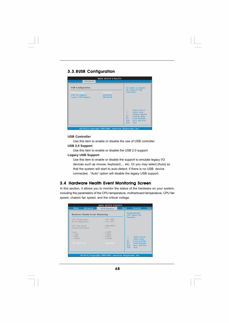
6868686868
3.3.83.3.83.3.83.3.83.3.8 USB ConfigurationUSB ConfigurationUSB ConfigurationUSB ConfigurationUSB Configuration
USB ControllerUse this item to enable or disable the use of USB controller.
USB 2.0 SupportUse this item to enable or disable the USB 2.0 support.
Legacy USB SupportUse this item to enable or disable the support to emulate legacy I/Odevices such as mouse, keyboard,... etc. Or you may select [Auto] sothat the system will start to auto-detect; if there is no USB deviceconnected, “Auto” option will disable the legacy USB support.
3.43.43.43.43.4 Hardware Health Event Monitoring ScreenHardware Health Event Monitoring ScreenHardware Health Event Monitoring ScreenHardware Health Event Monitoring ScreenHardware Health Event Monitoring ScreenIn this section, it allows you to monitor the status of the hardware on your system,including the parameters of the CPU temperature, motherboard temperature, CPU fanspeed, chassis fan speed, and the critical voltage.
BIOS SETUP UTILITY
Hardware Health Event Monitoring
Select ScreenSelect Item
F1 General HelpF9 Load DefaultsF10 Save and ExitESC Exit
v02.54 (C) Copyright 1985-2003, American Megatrends, Inc.
CPU TemperatureM / B Temperature
CPU Fan SpeedChassis Fan Speed
Vcore+ 3.30V+ 5.00V+ 12.00V
: 37 C / 98 F
: 3400 RPM: N / A
: 1.629V: 3.306V: 5.067V: 11.890V
: 31 C / 87 F
Main Advanced Boot Security ExitH/W Monitor
Enable/DisableCPU Quiet FanFunction.
CPU Quiet Fan [Disabled]
BIOS SETUP UTILITY
USB Configuration To enable or disablethe onboard USBcontrollers.
Select ScreenSelect Item
+- Change OptionF1 General HelpF9 Load DefaultsF10 Save and ExitESC Exit
v02.54 (C) Copyright 1985-2005, American Megatrends, Inc.
Advanced
USB Controller
USB 2.0 SupportLegacy USB Support
[Enabled]
[Enabled][Disabled]
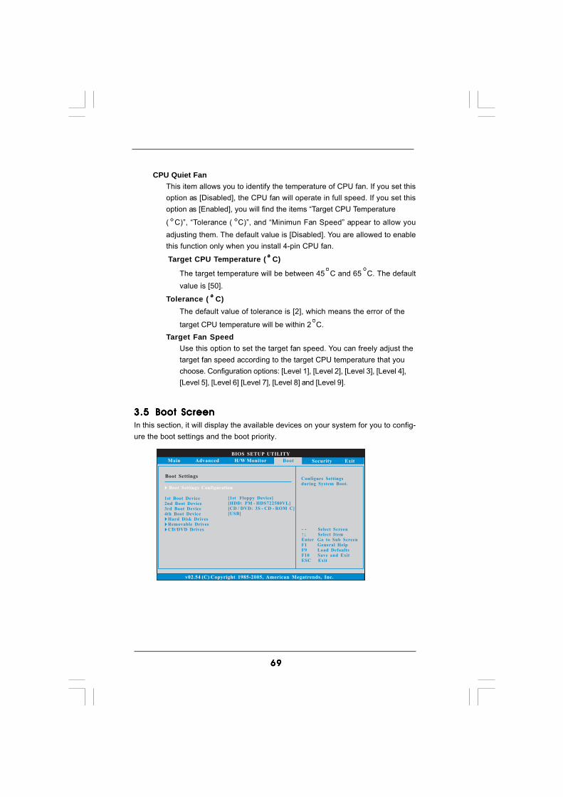
6969696969
3.53.53.53.53.5 Boot ScreenBoot ScreenBoot ScreenBoot ScreenBoot ScreenIn this section, it will display the available devices on your system for you to config-ure the boot settings and the boot priority.
BIOS SETUP UTILITY
Main Advanced H/W Monitor Security Exit
Boot SettingsConfigure Settingsduring System Boot.
Select ScreenSelect Item
Enter Go to Sub ScreenF1 General HelpF9 Load DefaultsF10 Save and ExitESC Exit
v02.54 (C) Copyright 1985-2005, American Megatrends, Inc.
Boot
Boot Settings Configuration
1st Boot Device2nd Boot Device3rd Boot Device4th Boot Device
Hard Disk DrivesRemovable DrivesCD/DVD Drives
[1st Floppy Device][HDD: PM - HDS722580VL][CD / DVD: 3S - CD - ROM C][USB]
CPU Quiet FanThis item allows you to identify the temperature of CPU fan. If you set thisoption as [Disabled], the CPU fan will operate in full speed. If you set thisoption as [Enabled], you will find the items “Target CPU Temperature
( C)”, “Tolerance ( C)”, and “Minimun Fan Speed” appear to allow youadjusting them. The default value is [Disabled]. You are allowed to enablethis function only when you install 4-pin CPU fan.
Target CPU Temperature ( C)
The target temperature will be between 45 C and 65 C. The defaultvalue is [50].
Tolerance ( C)The default value of tolerance is [2], which means the error of the
target CPU temperature will be within 2 C.Target Fan Speed
Use this option to set the target fan speed. You can freely adjust thetarget fan speed according to the target CPU temperature that youchoose. Configuration options: [Level 1], [Level 2], [Level 3], [Level 4],[Level 5], [Level 6] [Level 7], [Level 8] and [Level 9].
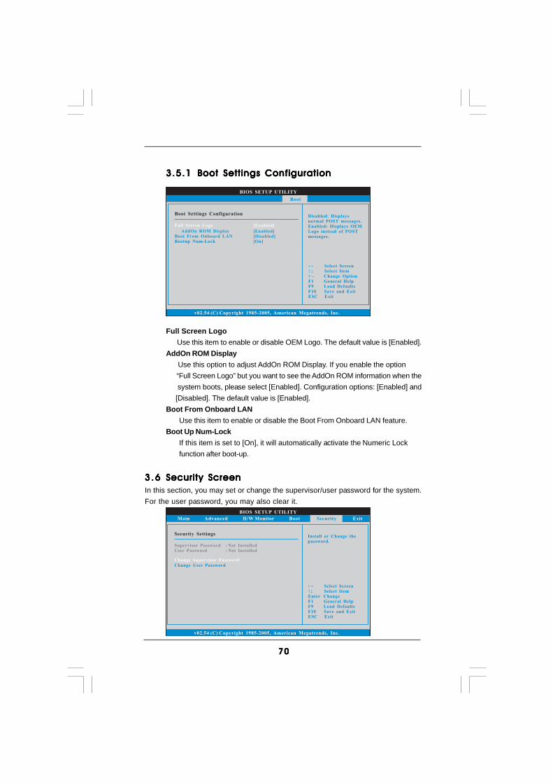
7070707070
3.5.13.5.13.5.13.5.13.5.1 Boot Settings ConfigurationBoot Settings ConfigurationBoot Settings ConfigurationBoot Settings ConfigurationBoot Settings Configuration
Full Screen Logo Use this item to enable or disable OEM Logo. The default value is [Enabled].AddOn ROM Display Use this option to adjust AddOn ROM Display. If you enable the option “Full Screen Logo” but you want to see the AddOn ROM information when the system boots, please select [Enabled]. Configuration options: [Enabled] and [Disabled]. The default value is [Enabled].Boot From Onboard LAN
Use this item to enable or disable the Boot From Onboard LAN feature.Boot Up Num-Lock
If this item is set to [On], it will automatically activate the Numeric Lockfunction after boot-up.
3.63 .63 .63 .63 .6 Security ScreenSecurity ScreenSecurity ScreenSecurity ScreenSecurity ScreenIn this section, you may set or change the supervisor/user password for the system.For the user password, you may also clear it.
BIOS SETUP UTILITY
Main Advanced H/W Monitor Boot Exit
Install or Change thepassword.
Select ScreenSelect Item
Enter ChangeF1 General Help
F10 Save and ExitESC Exit
F9 Load Defaults
v02.54 (C) Copyright 1985-2005, American Megatrends, Inc.
Security
Change Supervisor Password
Change User Password
Security Settings
Supervisor Password : Not InstalledUser Password : Not Installed
BIOS SETUP UTILITY
Boot Settings ConfigurationDisabled: Displaysnormal POST messages.Enabled: Displays OEMLogo instead of POSTmessages.
Select ScreenSelect Item
+ - Change OptionF1 General HelpF9 Load DefaultsF10 Save and ExitESC Exit
v02.54 (C) Copyright 1985-2005, American Megatrends, Inc.
Boot
AddOn ROM DisplayBoot From Onboard LANBootup Num-Lock
[Enabled][Disabled][On]
Full Screen Logo [Enabled]

7171717171
3.73.73.73.73.7 Exit ScreenExit ScreenExit ScreenExit ScreenExit Screen
Save Changes and ExitWhen you select this option, it will pop-out the following message, “Saveconfiguration changes and exit setup?” Select [OK] to save the changesand exit the BIOS SETUP UTILITY.
Discard Changes and ExitWhen you select this option, it will pop-out the following message, “Dis-card changes and exit setup?” Select [OK] to exit the BIOS SETUP UTILITYwithout saving any changes.
Discard ChangesWhen you select this option, it will pop-out the following message, “Dis-card changes?” Select [OK] to discard all changes.
Load Optimal DefaultsWhen you select this option, it will pop-out the following message, “Loadoptimal defaults?” Select [OK] to load the default values for all the setupconfigurations.
BIOS SETUP UTILITY
Main Advanced H/W Monitro Boot Security
Exit system setupafter saving thechanges.
F10 key can be usedfor this operation.
Select ScreenSelect Item
Enter Go to Sub ScreenF1 General Help
F10 Save and ExitESC Exit
F9 Load Defaults
v02.54 (C) Copyright 1985-2005, American Megatrends, Inc.
Exit
Save Changes and Exit
Discard Changes and ExitDiscard Changes
Load Optimal Defaults
Exit Options
7272727272
Chapter 4: Software SupporChapter 4: Software SupporChapter 4: Software SupporChapter 4: Software SupporChapter 4: Software Supporttttt4.14.14.14.14.1 Install Operating SystemInstall Operating SystemInstall Operating SystemInstall Operating SystemInstall Operating System
This motherboard supports various Microsoft® Windows® operating systems: 2000 /XP / XP 64-bit / VistaTM / VistaTM 64-bit. Because motherboard settings and hardwareoptions vary, use the setup procedures in this chapter for general reference only.Refer to your OS documentation for more information.
4.24 .24 .24 .24 .2 Support CD InformationSupport CD InformationSupport CD InformationSupport CD InformationSupport CD Information
The Support CD that came with the motherboard contains necessary drivers anduseful utilities that enhance the motherboard features.
4.2.14.2.14.2.14.2.14.2.1 Running The Support CDRunning The Support CDRunning The Support CDRunning The Support CDRunning The Support CD
To begin using the support CD, insert the CD into your CD-ROM drive. The CDautomatically displays the Main Menu if “AUTORUN” is enabled in your computer.If the Main Menu did not appear automatically, locate and double click on thefile “ASSETUP.EXE” from the BIN folder in the Support CD to display the menus.
4.2.24.2.24.2.24.2.24.2.2 Drivers MenuDrivers MenuDrivers MenuDrivers MenuDrivers Menu
The Drivers Menu shows the available devices drivers if the system detectsinstalled devices. Please install the necessary drivers to activate the devices.
4.2.34.2.34.2.34.2.34.2.3 Uti l i t ies MenuUti l i t ies MenuUti l i t ies MenuUti l i t ies MenuUti l i t ies Menu
The Utilities Menu shows the applications software that the motherboardsupports. Click on a specific item then follow the installation wizard to install it.
4.2.44.2.44.2.44.2.44.2.4 Contact Informat ionContact Informat ionContact Informat ionContact Informat ionContact Informat ion
If you need to contact ASRock or want to know more about ASRock, welcometo visit ASRock’s website at http://www.asrock.com; or you may contact yourdealer for further information.
Related Documents