Bureau of Project Delivery |Construction & Materials Division 400 North Street, 7 th Floor | Harrisburg, PA 17120 | 717.787.6989 | www.penndot.gov 481-18-03 DATE: April 19, 2018 SUBJECT: Rocscience SLIDE® Slope Stability Analysis Software Required for PennDOT Projects TO: District Executives FROM: George W. McAuley, Jr., P.E. /s/ Deputy Secretary for Highway Administration This time–neutral Strike-Off Letter requires the use of Rocscience’s SLIDE® software for all PennDOT projects with geotechnical constituents for new engineering agreements or new supplements not yet in the preliminary design phase. The implementation of SLIDE software was due to the completion of the transition and analysis period for slope stability software. Rocscience’s SLIDE ® software is designed to be a 2D limit equilibrium slope stability analysis program for all types of soil slopes. SLIDE includes built-in finite element groundwater seepage analysis, probabilistic analysis, multi-scenario modeling, and support design. PennDOT is requiring Central Office and the Districts to use SLIDE7.0 or the most current version. Business Partners responsible for geotechnical constituents in the project development process may use any slope stability software for preliminary design/analysis for PennDOT projects. However, the final slope stability design or analysis must be submitted to PennDOT using the most recent version of SLIDE software. Detailed information for integrating SLIDE software into the project development process for both Districts and Business Partners is provided in Attachment A. Please direct any questions or concerns regarding this matter to Kerry Petrasic, P.E., at (717) 787- 4319 or e-mail [email protected], or Kruz Schrann at (717) 787-4319 or e-mail [email protected]. Attachment

Welcome message from author
This document is posted to help you gain knowledge. Please leave a comment to let me know what you think about it! Share it to your friends and learn new things together.
Transcript

Bureau of Project Delivery |Construction & Materials Division 400 North Street, 7th Floor | Harrisburg, PA 17120 | 717.787.6989 | www.penndot.gov
481-18-03
DATE: April 19, 2018
SUBJECT: Rocscience SLIDE® Slope Stability Analysis Software Required for PennDOT Projects
TO: District Executives
FROM: George W. McAuley, Jr., P.E. /s/ Deputy Secretary for Highway Administration
This time–neutral Strike-Off Letter requires the use of Rocscience’s SLIDE® software for all PennDOT projects with geotechnical constituents for new engineering agreements or new supplements not yet in the preliminary design phase. The implementation of SLIDE software was due to the completion of the transition and analysis period for slope stability software.
Rocscience’s SLIDE ® software is designed to be a 2D limit equilibrium slope stability analysis program for all types of soil slopes. SLIDE includes built-in finite element groundwater seepage analysis, probabilistic analysis, multi-scenario modeling, and support design.
PennDOT is requiring Central Office and the Districts to use SLIDE7.0 or the most current version. Business Partners responsible for geotechnical constituents in the project development process may use any slope stability software for preliminary design/analysis for PennDOT projects. However, the final slope stability design or analysis must be submitted to PennDOT using the most recent version of SLIDE software.
Detailed information for integrating SLIDE software into the project development process for both Districts and Business Partners is provided in Attachment A.
Please direct any questions or concerns regarding this matter to Kerry Petrasic, P.E., at (717) 787- 4319 or e-mail [email protected], or Kruz Schrann at (717) 787-4319 or e-mail [email protected].
Attachment

SOL 481-18-03 Page 2 April 19, 2018
481/KNS/KWP/jdm
cc: George W. McAuley, P.E., 8th Floor CKB Daryl R. St. Clair, P.E., 8th Floor, CKB Natasha Fackler, 8th Floor, CKB Highway Administration Bureau Directors Project Delivery Division Chiefs Assistant District Executives – Design Assistant District Executives – Construction Assistant District Executives – Maintenance Assistant District Executives – Services Joseph S. Robinson, P.E., MTL Kerry W. Petrasic, P.E., MTL Dennis Q. Neff, P.E., MTL Beverly L. Miller, P.E., MTL Kruz N. Schrann, MTL District Bridge Engineers District Geotechnical Engineers District Structure Control Engineers Moises Marrero, Federal Highway Administration Leeann MacWilliams, ACEC Robert Latham, Associated Pennsylvania Constructors Pennsylvania Turnpike Commission Prequalified Drilling Contractors

Attachment A: Details for Incorporating Rocscience SLIDE Software on PennDOT Projects with Geotechnical Components

The implementation of Rocscience SLIDE® software for PennDOT projects with geotechnical components may affect various aspects of the project development process. Detailed information for Districts and Business Partners for obtaining SLIDE software and for integrating SLIDE into the project development process is available by clicking any of the items in the list, below:
1. Obtaining Rocscience SLIDE® Software2. Publication Updates:
• Attachment B: Publication 15M - Design Manual, Part 4 (DM-4), Section 10,Article 10.6.2.5
• Publication 293, Geotechnical Engineering Manual, Chapter 1, Chapter 5, andChapter 11
• Accepted Commercially Available or Consultant Developed Software3. RocScience SLIDE® Software Training
1. Obtaining Rocscience SLIDE® Software
PennDOT:SLIDE7.0 is covered under PennDOT’s Enterprise License Service Agreement withRocscience. SLIDE was previously deployed three years ago during a transition period toall District Geotechnical personnel and is now being implemented for sole use. PennDOThas a sufficient number of concurrent SLIDE licenses. However, PennDOT personnelusing SLIDE will need to be diligent in logging off when SLIDE is not in use in order toguarantee availability to all PennDOT SLIDE users.
Business Partners:Geotechnical Business Partners are required to use SLIDE7.0 software when submittingthe final slope stability design or analysis to PennDOT. Business Partners can purchaseSLIDE software from Rocscience (www.rocscience.com).
2. Publication Updates: Pub. 15M - Design Manual, Part 4 and Pub. 293, GeotechnicalEngineering Manual
Modifications to Design Manual, Part 4 (DM-4) and various sections of Publication 293 Chapter 1, Chapter 5, and Chapter 11 were required to address the implementation of SLIDE software. Additionally, the Department’s list of “Accepted Commercially Available or Consultant Developed Software” is updated.
DM-4: Section 10, Article 10.6.2.5 will replace the language for the use of GSTABL software to the use of SLIDE software. The replacement pages for DM-4 are included in Attachment B. The annotated version of DM-4, available free of charge through the Department’s website, has been updated to indicate where these changes occur.
Pub. 293: Publication 293, Chapter 1, Section 1.5.5.4; Chapter 5, Section 5.5.3.1.4; Chapter 11, Section 11.2, 11.8.2, and 11.8.3 has been revised to replace the language for the use of GSTABL software to the use of SLIDE software. Publication 293 is currently available free of charge through the Department’s website: Publication 293.
Accepted Commercially Available or Consultant Developed Software: This on-line list (that updates DM-4, Appendix J) has been revised to remove GSTABL7 with STEDwin, and to update the accepted version of SLIDE to version 7.0. The updated pages are included in Attachment C.
3. RocScience SLIDE® Software Training
For PennDOT Users:PennDOT has created PennDOT Powerpoint Tutorials for the in-house direction and useof Slide v7.0. PennDOT has also provided access to Rocscience tutorials and manual.These can be accessed on the P drive at the following location or at the links presentedbelow for business partners:
P:\Slide v7.0
For Business Partners:

Business Partners can access program documentation, tutorials, FAQ’s, example problem sets and SLIDE verification examples. Rocscience offers webinars, workshops, and short courses. These can be accessed at the following links:
Documentation: https://www.rocscience.com/rocscience/products/slide
Tutorials: https://www.rocscience.com/help/slide/webhelp7/tutorials/Slide_Tutorials.htm
FAQ’s: https://www.rocscience.com/support/find-an-answer
Sample Problems: https://www.rocscience.com/documents/pdfs/education/Slide_Problem_Sets
Training: https://www.rocscience.com/support/training
Webinars: https://www.rocscience.com/learning/professional-development/webinars
Rocscience also has additional resources available online at the following links:
https://www.rocscience.com/rocscience/products/slide/features
https://www.rocscience.com/learning/resource-library
https://www.rocscience.com/rocscience/products/slide/resources/researchpapers
https://www.rocscience.com/rocscience/products/slide/resources/developers-tips
Attachment B: Publication 15M - Design Manual, Part 4, Replacement Pages
Revision to Publication 15M - Design Manual, Part 4 (DM-4):
• Amend DM-4 Section 10, Article 10.6.2.5 to address the use of SLIDE rather than theuse of GSTABL.

DM-4, Section 10 – Foundations April 2018
SPECIFICATIONS COMMENTARY
B.10 - 22
10.6.2.4.3 Settlement of Footings on Cohesive Soils
The following shall supplement A10.6.2.4.3. For foundations on stiff cohesive soils, the elastic
settlement may be determined using Eq. D10.6.2.4.2-1.
C10.6.2.4.3
The following shall replace the third paragraph of AC10.6.2.4.3.
To account for the decreasing stress with increased depth below a footing and variations in soil compressibility with depth, the compressible layer should be divided into vertical increments, i.e., typically 5.0 to 10.0 ft. for most normal width footings for highway applications, and the consolidation settlement of each increment analyzed separately. The number and thickness of compressible layers will depend on the total depth of compressible soil below the footing and the desired accuracy of the settlement computations. In general, layers should be thinnest near the footing base to account for rapid changes in vertical stress distribution due to the applied stress, and variations in σp′with depth. The total value of Sc is the summation of Sc for each increment.
The following shall supplement AC10.6.2.4.3. The use of spread footings when total consolidation
settlement exceeds serviceability limitations is undesirable and another foundation type should be considered.
10.6.2.4.4 Settlement of Footings on Rock
The following shall supplement A6.10.2.4.4. If soil-filled discontinuities are present below a footing,
settlement of such layers should be estimated using theprocedures for footings on soil.
10.6.2.5 Overall Stability
The following shall replace A10.6.2.5. The overall stability of footings, slope and foundation
soil or rock shall be evaluated using Load CombinationService I Limit State; the provisions of A3.4.1, D3.4.1,D3.4.1.1P, A10.5.2.3 and D11.6.2.3 and the resistancefactors given in Table 10.6.2.5-1P.
C10.6.2.5P
Overall stability refers to deep seated failures. Until a computer program is developed to analyze
overall stability which incorporates the LRFD methodology, the Department will use the factor of safety method where S.F. = 1/ and the SLIDE computer program (Rocscience).
Table 10.6.2.5-1P ‒ Minimum Resistance Factors, φ, for Overall Stability at the Service Limit State
GEOMETRY SPT* AND VISUAL CLASSIFICATION
SPT* AND LAB CLASSIFICATION
SPT* AND LAB STRENGTH TESTING
General Spread Footing 0.55 0.65 0.75
Abutment Supported Above Retaining Wall
Not Acceptable 0.55 0.65
* Standard Penetration Test data from soil borings.
The overall stability shall be evaluated using limiting equilibrium methods of analysis. Depending on whether theanticipated mode of failure is circular or planar, theModified Bishop Method (or equivalent) or the Janbu
The Modified Bishop Method is appropriate where the failure surface is expected to be circular. The Janbu Method is appropriate where the failure surface is expected to be planar.
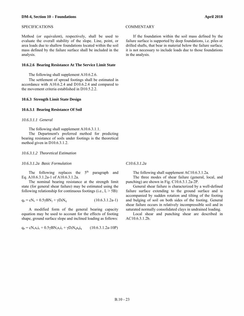
DM-4, Section 10 – Foundations April 2018
SPECIFICATIONS COMMENTARY
B.10 - 23
Method (or equivalent), respectively, shall be used toevaluate the overall stability of the slope. Line, point, orarea loads due to shallow foundations located within the soilmass defined by the failure surface shall be included in theanalysis.
If the foundation within the soil mass defined by the failure surface is supported by deep foundations, i.e. piles or drilled shafts, that bear in material below the failure surface, it is not necessary to include loads due to those foundations in the analysis.
10.6.2.6 Bearing Resistance At The Service Limit State
The following shall supplement A10.6.2.6. The settlement of spread footings shall be estimated in
accordance with A10.6.2.4 and D10.6.2.4 and compared tothe movement criteria established in D10.5.2.2.
10.6.3 Strength Limit State Design
10.6.3.1 Bearing Resistance Of Soil
10.6.3.1.1 General
The following shall supplement A10.6.3.1.1. The Department's preferred method for predicting
bearing resistance of soils under footings is the theoreticalmethod given in D10.6.3.1.2.
10.6.3.1.2 Theoretical Estimation
10.6.3.1.2a Basic Formulation
The following replaces the 5th paragraph andEq. A10.6.3.1.2a-1 of A10.6.3.1.2a.
The nominal bearing resistance at the strength limitstate (for general shear failure) may be estimated using thefollowing relationship for continuous footings (i.e., L > 5B):
qn = cNc + 0.5γBNγ + γDfNq (10.6.3.1.2a-1)
A modified form of the general bearing capacityequation may be used to account for the effects of footingshape, ground surface slope and inclined loading as follows:
qn = cNcscic + 0.5γBNγsγiγ + γDfNqsqiq (10.6.3.1.2a-10P)
C10.6.3.1.2a
The following shall supplement AC10.6.3.1.2a. The three modes of shear failure (general, local, and
punching) are shown in Fig. C10.6.3.1.2a-2P. General shear failure is characterized by a well-defined
failure surface extending to the ground surface and is accompanied by sudden rotation and tilting of the footing and bulging of soil on both sides of the footing. General shear failure occurs in relatively incompressible soil and in saturated normally consolidated clays in undrained loading.
Local shear and punching shear are described in AC10.6.3.1.2b.

Attachment C: Accepted Commercially Available or Consultant Developed Software
Revision to Accepted Commercially Available or Consultant Developed Software:
• Amend the on-line list to remove GSTABL7 with STEDwin, and to update theaccepted version of SLIDE to version 7.0.

BRIDGE DESIGN AND TECHNOLOGY DIVISION
ACCEPTED COMMERCIALLY AVAILABLE ORCONSULTANT DEVELOPED SOFTWARE
(UPDATED APRIL 19, 2018)
Recent Updates:4/19/2018 - For geotechnical slope stability analysis, SLIDE v7.0 is required; GSTABL7 and SLIDE
v6.0 are no longer acceptable.
7/27/2017 - Accepted LOAD3D v2.0 (SAI Consulting Engineers, Inc.) for LRFD design, analysis and rating.
7/26/2017 - Accepted LOAD3D v2.0 (SAI Consulting Engineers, Inc.) for Load Factor Ratings.
The software and programs listed herein have been tested and accepted for use on Department projects as indicated. Unless noted otherwise, only the listed version of a program, if given, has been tested and accepted. The following content had previously been provided in Appendix J of Design Manual, Part 4.
3D AND REFINED METHODS OF ANALYSISListed below are computer programs accepted for 3D or Refined Analysis to determine Load Factor Ratings (LFR) and for LRFD analysis and ratings. The acceptance of these programs is subject to the following conditions and limitations:
1. While certain software packages provide design optimization and/or code compliance checks, theseaspects were not included in the review process. Acceptance has been based solely upon the reviewof generalized design forces (moments, shears, reactions, etc.) as calculated by the software.
2. Acceptance of a software package by the Department does not affect the responsibility of the designerfor the proper application of the software and interpretation of its results. The acceptance of asoftware package does not constitute an endorsement nor does it relieve the vendor or the designerfrom their responsibility for accurate, technically correct, and sound engineering results and services tothe Department.
3. The Department's acceptance does not constitute any form of implied warranty, including warranty ofmerchantability and fitness for a particular purpose. The Commonwealth makes no warranty orrepresentation, either expressed or implied, with respect to this software or accompanyingdocumentation, including their quality performance, merchantability, or fitness for a particular purpose.In addition, the Commonwealth will not be liable for any direct, indirect, special, incidental, orconsequential damages arising out of the use, inability to use, or any defect in the software or anyaccompanying documentation.

Only the version of a program listed in the tables below has been tested and accepted. If any changes and/or modifications are made to a program after its acceptance date, re-evaluation and acceptance of the program is required.
Load Factor Ratings (LFR)
ACCEPTED SOFTWARE VENDOR / CONSULTANT ACCEPTED
AASHTOWare Bridge Design and Rating, v6.6.0 AASHTO (Washington, D.C.) 6/16/2014
BSMStudio, v1.5 Fynite Solutions, LLC (Moon Township, PA) 12/22/2014
CSiBridge, 2015, v16 through v19 Computers & Structures, Inc. (Walnut Creek, CA) 8/21/2014
LARSA 4D Bridge, v7.08.05 LARSA, Inc. (Melville, NY) 7/28/2016
LEAP Bridge Steel, CONNECT Edition, v16 and v17 Bentley Systems, Inc. (Exton, PA) 4/20/2016
LOAD3D v2.0 SAI Consulting Engineers, Inc. (Pittsburgh, PA) 7/26/2017
LUSAS+VLO v15.0 (Vehicle Load Opt.) LUSAS (New York, NY) 12/31/2014
Consultants utilizing these programs will need to submit sample calculations that demonstrate their proficiency with the software to properly perform a 3D finite element structural analysis including moving loads, influence surface generation, and subsequent design code checks.
LRFD Analysis and Rating
ACCEPTED SOFTWARE VENDOR / CONSULTANT ACCEPTED
AASHTOWare Bridge Design and Rating, v6.6.0 AASHTO (Washington, D.C.) 12/3/2014
BSMStudio, v1.5 Fynite Solutions, LLC (Moon Township, PA) 12/31/2014
CSiBridge, 2015, v16 through v19 Computers & Structures, Inc. (Walnut Creek, CA) 12/2/2014
LARSA 4D Bridge, v7.08.05 LARSA, Inc. (Melville, NY) 2/15/2017
LEAP Bridge Steel, CONNECT Edition, v16 and v17 Bentley Systems, Inc. (Exton, PA) 5/19/2016
LOAD3D v2.0 SAI Consulting Engineers, Inc. (Pittsburgh, PA) 7/27/2017
LUSAS+VLO v15.0 (Vehicle Load Opt.) LUSAS (New York, NY) 11/3/2015
Consultants utilizing these programs will need to submit sample calculations that demonstrate their proficiency with the software to properly perform a 3D finite element structural analysis including moving loads, influence surface generation, and subsequent design code checks.

GENERAL PURPOSE STRUCTURAL ANALYSIS▪ STAAD.Pro V8i (Bentley Systems, Inc.)
The following features have not yet proven satisfactory to the Department and shall not be used:1. The analysis of moving live loads on two- or three-dimensional structural models, load rating
determination, and all design code check capabilities.2. The response spectrum and forced vibration analysis capabilities, or seismic design and analyses.
▪ LUSAS v15.0 (without Vehicle Load Optimization) (LUSAS)The following features have not yet proven satisfactory to the Department and shall not be used:1. The analyses of LRFD moving live loads on two- or three-dimensional structural models, load
rating determination, and all design code check capabilities.2. The response spectrum and forced vibration analysis capabilities, or seismic design and analyses.3. Analyses involving the non-linear behavior of material properties.
▪ BSMStudio (Fynite Solutions, LLC)The following features have not yet proven satisfactory to the Department and shall not be used:1. All design code check capabilities.2. The response spectrum and forced vibration analysis capabilities, or seismic design and analyses.
▪ SAP2000 v19.1.0 (Computers and Structures, Inc.) [Accepted 5/3/2017]The following features have not yet proven satisfactory to the Department and shall not be used:1. The analyses of LRFD moving live loads on two- or three-dimensional structural models, load
rating determination, and all design code check capabilities.2. The response spectrum and forced vibration analysis capabilities, or seismic design and analyses.3. Analyses involving the non-linear behavior of material properties.
PIER ANALYSIS▪ VBent v3.4.0 (Viathor, Inc.)
BURIED PRECAST CONCRETE PIPE DESIGN AND ANALYSIS▪ PIPECAR (FHWA)
SEISMIC DESIGN AND ANALYSIS OF GIRDER BRIDGES▪ WinSEISAB v5.1.0 (TRC Software LLC)

GEOTECHNICAL DESIGN AND ANALYSIS
Pile Hammer WEAP Analysis (refer to DM-4 Article 10.7.3.8.4aP)▪ GRLWEAP 2010 (Pile Dynamics, Inc.)
Ultimate Vertical Static Pile Capacity (refer to FHWA Report SA-98-074, AASHTO Article 10.7.3.8.6 and DM-4 Article 10.7.3.8.6)▪ DRIVEN v1.2 (FHWA)
▪ AllPile (CivilTech Software)
Laterally Loaded Piles and Drilled Shafts (refer to DM-4 Article 10.7.3.12.2P)▪ COM624P (Ensoft, Inc.)
▪ LPILE (Ensoft, Inc.)
Slope Stability Analysis (refer to PennDOT Pub. 293 and DM-4 Article 10.6.2.5)▪ SLIDE v7.0 (Rocscience Inc.)
INQUIRIES AND SUBMISSIONSFor more information about software acceptance and pre-qualification for utilizing software, or to make a submission and initiate the acceptance review process, please contact:
Pennsylvania Department of TransportationBridge Design and Technology DivisionATTN: Paul E. Brandl, P.E.400 North Street, 7th FloorHarrisburg, PA 17120(717) 787-7057 | [email protected]
Related Documents