Volume 2 (Technical Handbook) Georgia Stormwater Management Manual 4.8-18989 4.8 Enhanced Swales Best Management Practice Description: Vegetated open channels that are explicitly designed and constructed to capture and treat stormwater runoff within dry or wet cells formed by check dams or other means. LID/GI Consideration: Adaptable to many linear situations, and often a small BMP used to treat runoff close to the source. KEY CONSIDERATIONS DESIGN CRITERIA: Longitudinal slopes must be less than 4% Bottom width of 2 to 8 feet Side slopes 2:1 or flatter; 4:1 recommended Convey the 25-year storm event with a minimum of 6 inches of freeboard ADVANTAGES / BENEFITS: Combines stormwater treatment with runoff conveyance system Less expensive than curb and gutter Reduces runoff velocity DISADVANTAGES / LIMITATIONS: Higher maintenance than curb and gutter systems Cannot be used on steep slopes Possible resuspension of sediment Potential for odor / mosquitoes (wet swale) MAINTENANCE REQUIREMENTS: Maintain grass heights of approximately 4 to 6 inches (dry swale) Remove sediment from forebay and channel STORMWATER MANAGEMENT SUITABILITY Water Quality Channel Protection Overbank Flood Protection Extreme Flood Protection -suitable for this practice in certain situationsmay provide partial benefitsAccepts Hotspot Runoff: Yes (requires impermeable liner) in certain situations IMPLEMENTATION CONSIDERATIONS Land Requirement Capital Cost Maintenance Burden Residential Subdivision Use: Yes High Density/Ultra-Urban: No Drainage Area: 5 acres max. HM M L Commented [A1]: For the final formatted version, a symbol different from a star will be chosen.

Welcome message from author
This document is posted to help you gain knowledge. Please leave a comment to let me know what you think about it! Share it to your friends and learn new things together.
Transcript

Volume 2 (Technical Handbook) Georgia Stormwater Management Manual 4.8-18989
4.8 Enhanced Swales Best Management Practice
Description: Vegetated open channels
that are explicitly designed and constructed to capture and treat stormwater runoff within dry or wet cells formed by check dams or other means. LID/GI Consideration: Adaptable to
many linear situations, and often a small BMP used to treat runoff close to the source.
KEY CONSIDERATIONS
DESIGN CRITERIA:
Longitudinal slopes must be less than 4%
Bottom width of 2 to 8 feet
Side slopes 2:1 or flatter; 4:1 recommended
Convey the 25-year storm event with a minimum of 6 inches of freeboard
ADVANTAGES / BENEFITS:
Combines stormwater treatment with runoff conveyance system
Less expensive than curb and gutter
Reduces runoff velocity
DISADVANTAGES / LIMITATIONS:
Higher maintenance than curb and gutter systems
Cannot be used on steep slopes
Possible resuspension of sediment
Potential for odor / mosquitoes (wet swale)
MAINTENANCE REQUIREMENTS:
Maintain grass heights of approximately 4 to 6 inches (dry swale)
Remove sediment from forebay and channel
STORMWATER MANAGEMENT
SUITABILITY
Water Quality
Channel Protection
Overbank Flood Protection
Extreme Flood Protection
-suitable for this practice in certain situationsmay provide partial benefitsAccepts Hotspot Runoff: Yes
(requires impermeable liner)
in certain situations
IMPLEMENTATION
CONSIDERATIONS
Land Requirement
Capital Cost
Maintenance Burden
Residential Subdivision Use: Yes
High Density/Ultra-Urban: No
Drainage Area: 5 acres max.
HM
M
L
Commented [A1]: For the final formatted version, a symbol different from a star will be chosen.
3.24.8-290 Georgia Stormwater Management Manual Volume 2 (Technical Handbook)
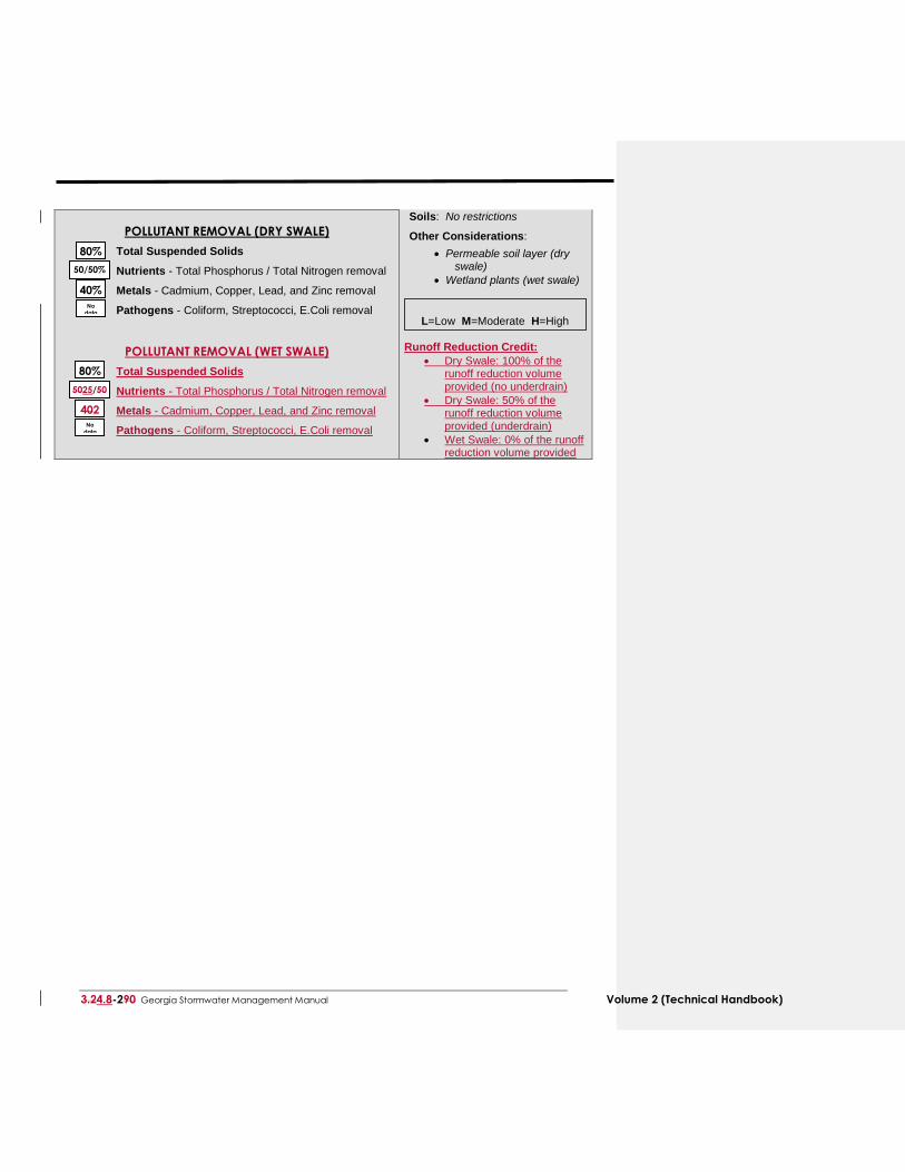
POLLUTANT REMOVAL (DRY SWALE)
Total Suspended Solids
Nutrients - Total Phosphorus / Total Nitrogen removal
Metals - Cadmium, Copper, Lead, and Zinc removal
Pathogens - Coliform, Streptococci, E.Coli removal
POLLUTANT REMOVAL (WET SWALE)
Total Suspended Solids
Nutrients - Total Phosphorus / Total Nitrogen removal
Metals - Cadmium, Copper, Lead, and Zinc removal
Pathogens - Coliform, Streptococci, E.Coli removal
Soils: No restrictions
Other Considerations:
Permeable soil layer (dry swale)
Wetland plants (wet swale)
L=Low M=Moderate H=High Runoff Reduction Credit:
Dry Swale: 100% of the runoff reduction volume provided (no underdrain)
Dry Swale: 50% of the runoff reduction volume provided (underdrain)
Wet Swale: 0% of the runoff reduction volume provided
80%
40%
No
data
50/50%
5025/50
40%
80%
402
0% No
data
Volume 2 (Technical Handbook) Georgia Stormwater Management Manual 4.8-38989
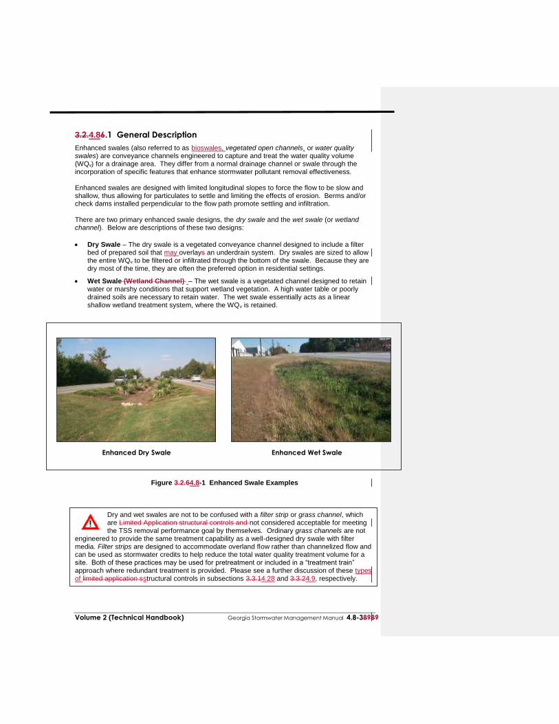
3.2.4.86.1 General Description
Enhanced swales (also referred to as bioswales, vegetated open channels, or water quality swales) are conveyance channels engineered to capture and treat the water quality volume (WQv) for a drainage area. They differ from a normal drainage channel or swale through the incorporation of specific features that enhance stormwater pollutant removal effectiveness. Enhanced swales are designed with limited longitudinal slopes to force the flow to be slow and shallow, thus allowing for particulates to settle and limiting the effects of erosion. Berms and/or check dams installed perpendicular to the flow path promote settling and infiltration. There are two primary enhanced swale designs, the dry swale and the wet swale (or wetland channel). Below are descriptions of these two designs:
Dry Swale – The dry swale is a vegetated conveyance channel designed to include a filter
bed of prepared soil that may overlays an underdrain system. Dry swales are sized to allow the entire WQv to be filtered or infiltrated through the bottom of the swale. Because they are dry most of the time, they are often the preferred option in residential settings.
Wet Swale (Wetland Channel) – The wet swale is a vegetated channel designed to retain water or marshy conditions that support wetland vegetation. A high water table or poorly drained soils are necessary to retain water. The wet swale essentially acts as a linear shallow wetland treatment system, where the WQv is retained.
Enhanced Dry Swale Enhanced Wet Swale
Figure 3.2.64.8-1 Enhanced Swale Examples
Dry and wet swales are not to be confused with a filter strip or grass channel, which are Limited Application structural controls and not considered acceptable for meeting the TSS removal performance goal by themselves. Ordinary grass channels are not
engineered to provide the same treatment capability as a well-designed dry swale with filter media. Filter strips are designed to accommodate overland flow rather than channelized flow and can be used as stormwater credits to help reduce the total water quality treatment volume for a site. Both of these practices may be used for pretreatment or included in a “treatment train” approach where redundant treatment is provided. Please see a further discussion of these types of limited application sstructural controls in subsections 3.3.14.28 and 3.3.24.9, respectively.
3.24.8-490 Georgia Stormwater Management Manual Volume 2 (Technical Handbook)
3.2.64.8.2 Stormwater Management Suitability
Enhanced swale systems are designed primarily for stormwater quality and have only a limited ability to provide channel protection or to convey higher flows to other controls. Water Quality
Dry swale systems rely primarily on filtration through an engineered media to provide removal of stormwater contaminants. Wet swales achieve pollutant removal both from sediment accumulation removal and biological removal. Section 3.2.64.8.3 provides median pollutant removal efficiencies that can be used for planning and design purposes.
Channel Protection
Generally only the WQv is treated by a dry or wet swale, and another structural control must be used to provide Cpv extended detention. However, for some smaller sites, a swale may be designed to capture and detain the full Cpv. Overbank Flood Protection
Enhanced swales must provide flow diversion and/or be designed to safely pass overbank flood flows. Another structural control must be used in conjunction with an enhanced swale system to reduce the post-development peak flow of the 25-year storm (Qp25) to pre-development levels (detention). Extreme Flood Protection
Enhanced swales must provide flow diversion and/or be designed to safely pass extreme storm flows. Another structural control must be used in conjunction with an enhanced swale system to reduce the post-development peak flow of the 100-year storm (Qf) if necessary.
3.2.64.8.3 Pollutant Removal Capabilities
Both the dry and wet enhanced swale are presumed to be able to remove 80% of the total suspended solids load in typical urban post-development runoff when sized, designed, constructed and maintained in accordance with the recommended specifications. Undersized or poorly designed swales can reduce TSS removal performance. The following design pollutant removal rates are conservative average pollutant reduction percentages for design purposes derived from sampling data, modeling and professional judgment. In a situation where a removal rate is not deemed sufficient, additional controls may be put in place at the given site in a series or “treatment train” approach.
Total Suspended Solids – 80%
Total Phosphorus – Dry Swale 50% / Wet Swale 25%
Total Nitrogen – Dry Swale 50% / Wet Swale 40%
Fecal Coliform – insufficient data
Heavy Metals – Dry Swale 40% / Wet Swale 20% For additional information and data on pollutant removal capabilities for enhanced dry and wet swales, see the National Pollutant Removal Performance Database (2nd EditionVersion 3) available at www.cwp.org and the National Stormwater Best Management Practices (BMP) Database at www.bmpdatabase.org.
Volume 2 (Technical Handbook) Georgia Stormwater Management Manual 4.8-58989
3.2.64.8.4 Application and Feasibility Criteria
Enhanced swales can be used in a variety of development types; however, they are primarily applicable to residential and institutional areas of low to moderate density where the impervious cover in the contributing drainage area is relatively small, and along roads and highways. Dry swales are mainly used in moderate to large lot residential developments, small impervious areas (parking lots and rooftops), and along rural highways. Wet swales tend to be used for highway runoff applications, small parking areas, and in commercial developments as part of a landscaped area. Because of their relatively large land requirement, enhanced swales are generally not used in higher density areas. In addition, wet swales may not be desirable for some residential applications, due to the presence of standing and stagnant water, which may create nuisance odor or mosquito problems. The topography and soils of a site will determine the applicability of the use of one of the two enhanced swale designs. Overall, the topography should allow for the design of a swale with sufficient slope and cross-sectional area to maintain non-erosive velocities. The following criteria should be evaluated to ensure the suitability of an enhanced swale stormwater pond for meeting stormwater management objectives on a site or development. General Feasibility
Suitable for Residential Subdivision Usage – YES
Suitable for High Density/Ultra Urban Areas – NO
Regional Stormwater Control – NO Physical Feasibility - Physical Constraints at Project Site
Drainage Area – 5 acres maximum
Space Required – Approximately 10 to 20% of the tributary impervious area
Site Slope – Typically no more than 4% channel slope
Minimum Head – Elevation difference needed at a site from the inflow to the outflow: 3 to 5 feet for dry swale; 1 foot for wet swale
Minimum Depth to Water Table – 2 feet required between the bottom of a dry swale and the elevation of the seasonally high water table, if an aquifer or treating a hotspot; wet swale is below water table or placed in poorly drained soils
Soils – Engineered media for dry swale
Other Constraints / Considerations
Aquifer Protection – Exfiltration should not be allowed for in hotspots areas
3.2.64.8.5 Planning and Design Criteria
The following criteria are to be considered minimum standards for the design of an enhanced
swale system. Consult with the local review authority to determine if there are any variations to these criteria or additional standards that must be followed. A. LOCATION AND SITING
A dry or wet swale should be sited such that the topography allows for the design of a channel with sufficiently mild slope (unless small drop structures are used) and cross-sectional area to maintain non-erosive velocities.
Enhanced swale systems should have a contributing drainage area of 5 acres or less. Swale siting should also take into account the location and use of other site features, such as
buffers and undisturbed natural areas, and should attempt to aesthetically “fit” the facility into the landscape.
3.24.8-690 Georgia Stormwater Management Manual Volume 2 (Technical Handbook)
A wet swale can be used where the water table is at or near the soil surface, or where there is a sufficient water balance in poorly drained soils to support a wetland plant community.
B. GENERAL DESIGN
Both types of enhanced swales are designed to treat the WQv through a volume-based design, and to safely pass larger storm flows. Flow enters the channel through a pretreatment forebay. Runoff can also enter along the sides of the channel as sheet flow through a the use of a pea gravel flow spreader, such as a pea gravel trench along the top of the bank.
Dry Swale
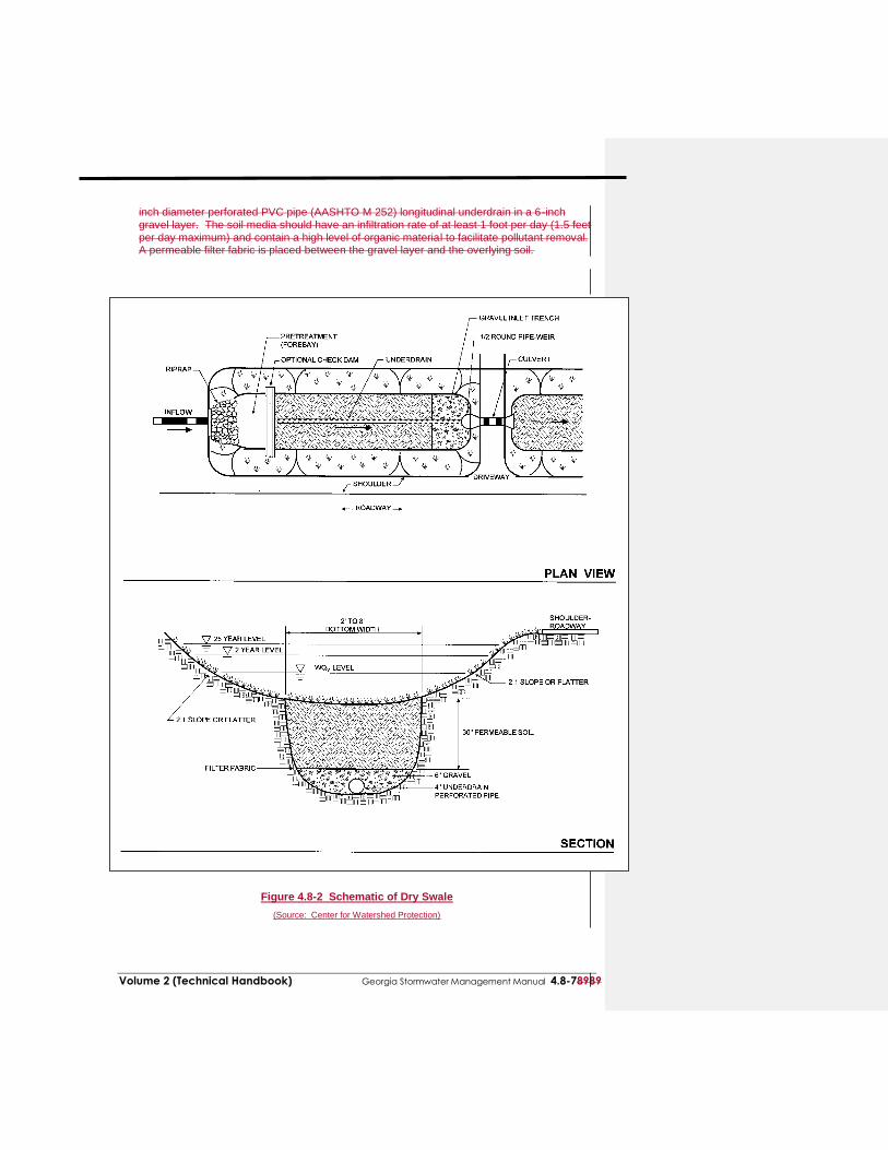
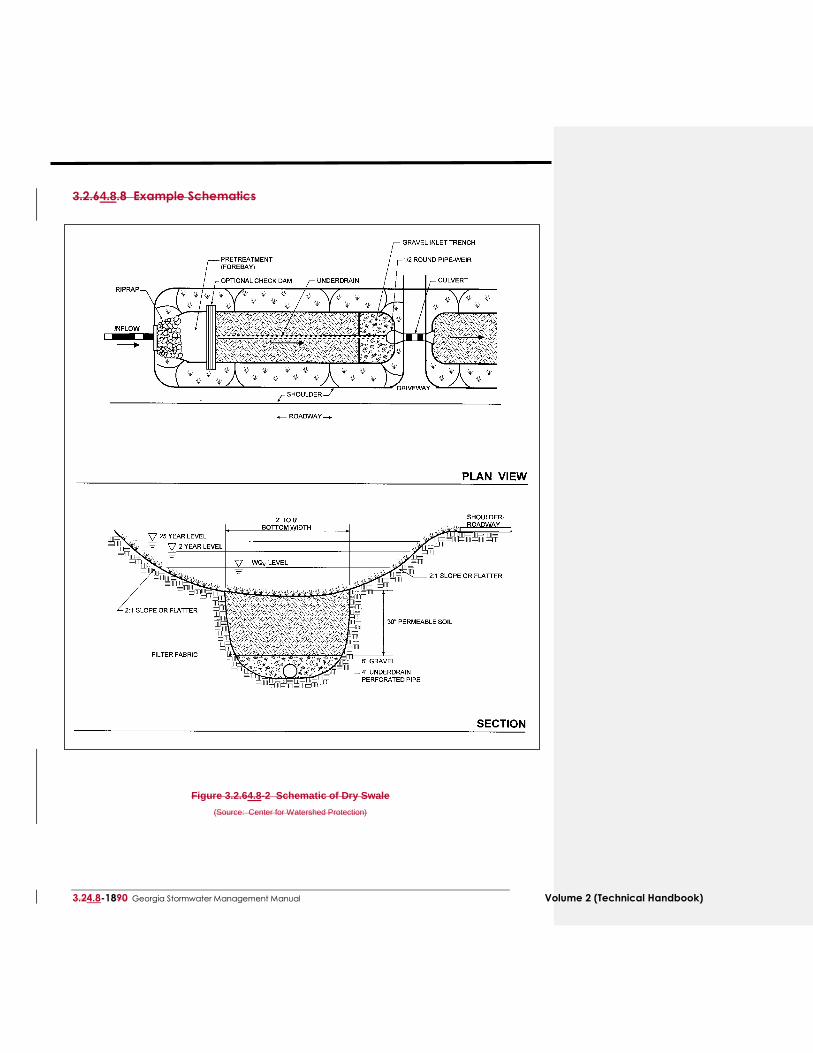
A dry swale system consists of an open conveyance channel with a filter bed of permeable soils that may overlays an underdrain system. Flow passes into and is detained in the main portion of the channel where it is filtered through the soil bed. Runoff may beis collected and conveyed by a perforated pipe and gravel underdrain system to the outlet. Figure 3.2.64.8-2 provides a plan view and profile schematic for the design of a dry swale system.
Wet Swale
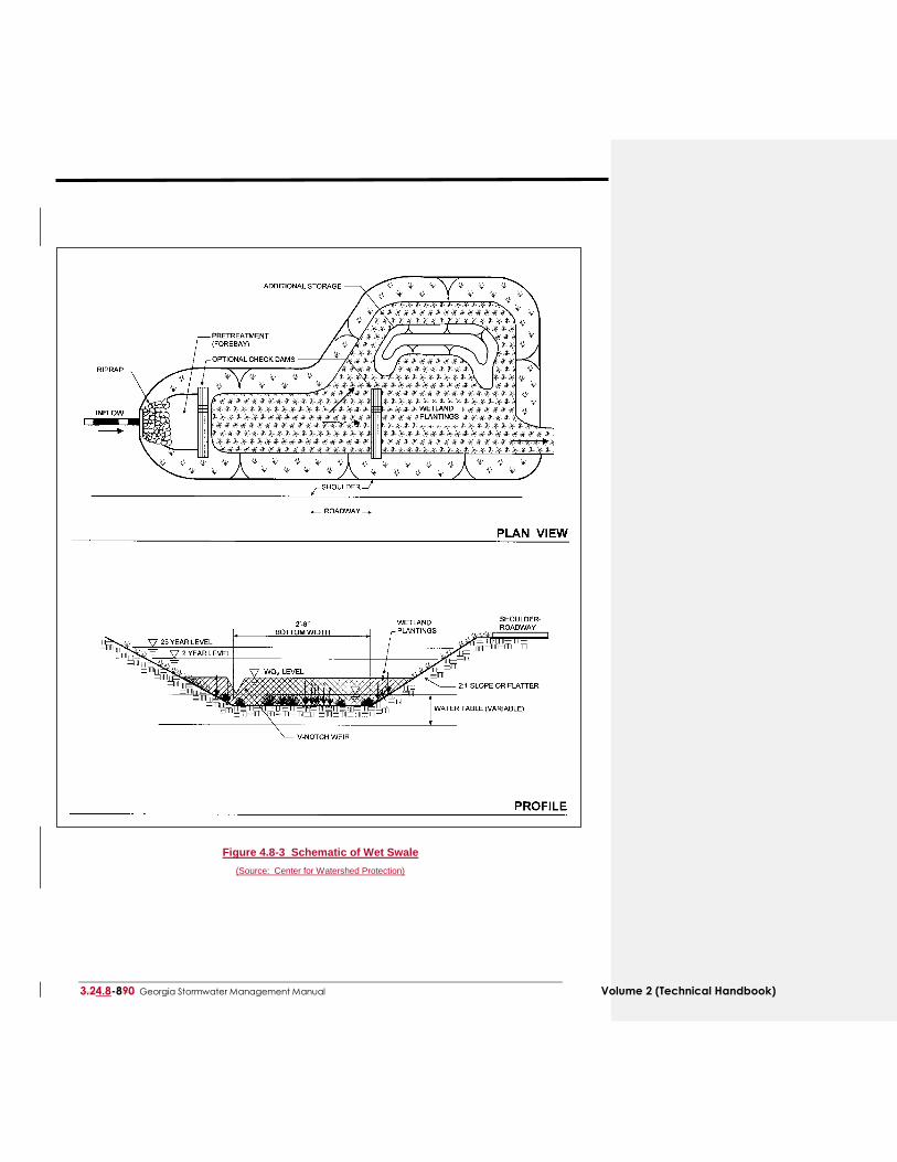
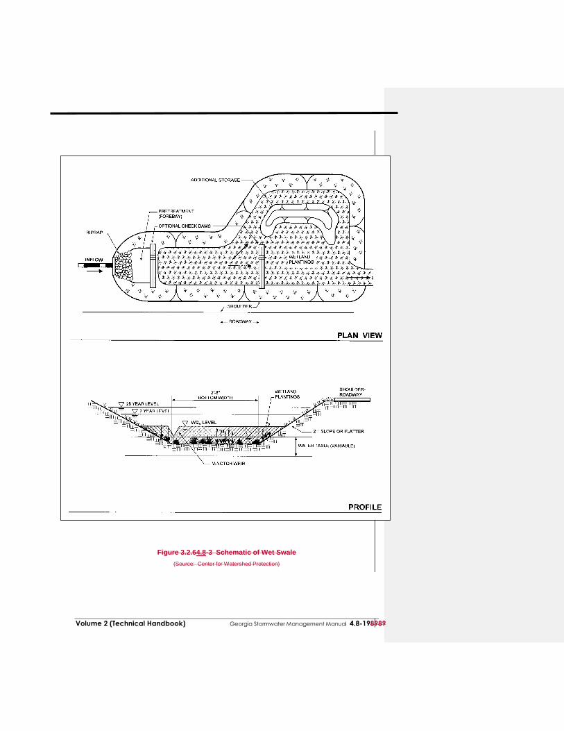
A wet swale or wetland channel consists of an open conveyance channel which has been excavated to the water table or to poorly drained soils. Check dams are used to create multiple wetland “cells,” which act as miniature shallow marshes. Figure 3.2.64.8-3 provides a plan view and profile schematic for the design of a wet swale system.
C. PHYSICAL SPECIFICATIONS / GEOMETRY
Channel slopes between 1% and 2% are recommended unless topography necessitates a steeper slope, in which case 6- to 12-inch drop structures can be placed to limit the energy slope to within the recommended 1 to 2% range. Energy dissipation will be required below the drops. Spacing between the drops should not be closer than 50 feet. Depth of the WQ v at the downstream end should not exceed 18 inches.
Dry and wet swales should have a bottom width of 2 to 8 feet to ensure adequate filtration.
Wider channels can be designed, but should contain berms, walls, or a multi-level cross section to prevent channel braiding or uncontrolled sub-channel formation.
Dry and wet swales are parabolic or trapezoidal in cross-section and are typically designed with moderate side slopes no greater than 2:1 for ease of maintenance and side inflow by sheet flow (4:1 or flatter recommended).
Dry and wet swales should maintain a maximum WQv ponding depth of 18 inches at the end point of the channel. A 12-inch average depth should be maintained.
The peak velocity for the 2-year storm must be non-erosive for the soil and vegetative cover provided.
If the system is on-line, channels should be sized to convey runoff from the overbank flood event (Qp25) safely with a minimum of 6 inches of freeboard and without damage to adjacent property.
Dry Swale
Dry swale channels are sized to store and infiltrate the entire water quality volume (WQv) with less than 18 inches of ponding and allow for full filtering through the permeable soil layer. The maximum ponding time is 48 hours, though a 24-hour ponding time is more desirable.
The dry swale consists of a permeable soil layer of at least 30 inches in depth, above an
underdrain. The soil media should have an infiltration rate of at least 1 foot per day (1.5 feet per day maximum) and contain a high level of organic material to facilitate pollutant removal. A permeable filter fabric is placed between the gravel layer and the overlying soil. Where an underdrain collection system is utilized, it should be equipped with at least a The 4-inch diameter perforated PVC pipe (AASHTO M 252) longitudinal underdrain in a gravel layer.bed of the dry swale consists of a permeable soil layer of at least 30 inches in depth, above a 4-
Volume 2 (Technical Handbook) Georgia Stormwater Management Manual 4.8-78989
inch diameter perforated PVC pipe (AASHTO M 252) longitudinal underdrain in a 6-inch gravel layer. The soil media should have an infiltration rate of at least 1 foot per day (1.5 feet per day maximum) and contain a high level of organic material to facilitate pollutant removal. A permeable filter fabric is placed between the gravel layer and the overlying soil.
Figure 4.8-2 Schematic of Dry Swale
(Source: Center for Watershed Protection)
3.24.8-890 Georgia Stormwater Management Manual Volume 2 (Technical Handbook)
Figure 4.8-3 Schematic of Wet Swale
(Source: Center for Watershed Protection)
Volume 2 (Technical Handbook) Georgia Stormwater Management Manual 4.8-98989
The channel and underdrain excavation should be limited to the width and depth specified in the design. The bottom of the excavated trench shall not be loaded in a way that causes soil compaction, and shall be scarified prior to placement of gravel and permeable soil. The sides of the channel shall be trimmed of all large roots. The sidewalls shall be uniform with no voids and scarified prior to backfilling.
Wet Swale
Wet swale channels are sized to retain the entire water quality volume (WQv) with less than 18 inches of ponding at the maximum depth point.
Check dams can be used to achieve multiple wetland cells. V-notch weirs in the check dams
can be utilized to direct low flow volumes. D. PRETREATMENT / INLETS
Inlets to enhanced swales must be provided with energy dissipators such as riprap. Pretreatment of runoff in both a dry and wet swale system is typically provided by a sediment
forebay located at the inlet. The pretreatment volume should be equal to 0.1 inches per impervious acre. This storage is usually obtained by providing check dams at pipe inlets and/or driveway crossings.
Enhanced swale systems that receive direct concentrated runoff may have a 6-inch drop to a
pea gravel diaphragm flow spreader at the upstream end of the control. A pea gravel diaphragmVegetated filter strips and gentle side slopes should be provided
along the top of channels to provide pretreatment for lateral sheet flows. E. OUTLET STRUCTURES
Dry Swale
The underdrain system should discharge to the storm drainage infrastructure or a stable outfall.
Wet Swale
Outlet protection must be used at any discharge point from a wet swale to prevent scour and downstream erosion.
F. EMERGENCY SPILLWAY
Enhanced swales must be adequately designed to safely pass flows that exceed the design storm flows.
G. MAINTENANCE ACCESS
Adequate access should be provided for all dry and wet swale systems for inspection and maintenance.
H. SAFETY FEATURES
Ponding depths should be limited to a maximum of 18 inches. I. LANDSCAPING
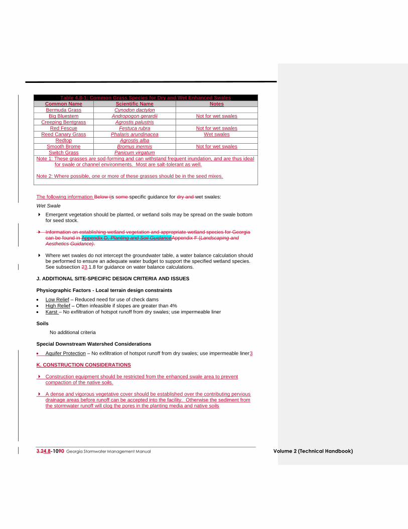
Landscape design should specify proper grass species and wetland plants based on specific site, soils and hydric conditions present along the channel. Table 4.8-1 below provides a number of grass species that perform well in the stressful environment of an open channel BMP. In addition, wet swales may include other wetland species (see plant list in Section 5 of Appendix D). Select plant material capable of salt tolerance in areas that may include high salt levels.
3.24.8-1090 Georgia Stormwater Management Manual Volume 2 (Technical Handbook)
Table 4.8-1: Common Grass Species for Dry and Wet Enhanced Swales
Common Name Scientific Name Notes
Bermuda Grass Cynodon dactylon
Big Bluestem Andropogon gerardii Not for wet swales
Creeping Bentgrass Agrostis palustris
Red Fescue Festuca rubra Not for wet swales
Reed Canary Grass Phalaris arundinacea Wet swales
Redtop Agrostis alba
Smooth Brome Bromus inermis Not for wet swales
Switch Grass Panicum virgatum
Note 1: These grasses are sod-forming and can withstand frequent inundation, and are thus ideal for swale or channel environments. Most are salt-tolerant as well.
Note 2: Where possible, one or more of these grasses should be in the seed mixes.
The following information Below iis some specific guidance for dry and wet swales:
Wet Swale
Emergent vegetation should be planted, or wetland soils may be spread on the swale bottom for seed stock.
Information on establishing wetland vegetation and appropriate wetland species for Georgia
can be found in Appendix D, Planting and Soil GuidanceAppendix F (Landscaping and Aesthetics Guidance).
Where wet swales do not intercept the groundwater table, a water balance calculation should
be performed to ensure an adequate water budget to support the specified wetland species. See subsection 23.1.8 for guidance on water balance calculations.
J. ADDITIONAL SITE-SPECIFIC DESIGN CRITERIA AND ISSUES Physiographic Factors - Local terrain design constraints
Low Relief – Reduced need for use of check dams
High Relief – Often infeasible if slopes are greater than 4%
Karst – No exfiltration of hotspot runoff from dry swales; use impermeable liner Soils
No additional criteria Special Downstream Watershed Considerations
Aquifer Protection – No exfiltration of hotspot runoff from dry swales; use impermeable liner3
K. CONSTRUCTION CONSIDERATIONS Construction equipment should be restricted from the enhanced swale area to prevent
compaction of the native soils.
A dense and vigorous vegetative cover should be established over the contributing pervious drainage areas before runoff can be accepted into the facility. Otherwise the sediment from the stormwater runoff will clog the pores in the planting media and native soils
Volume 2 (Technical Handbook) Georgia Stormwater Management Manual 4.8-118989
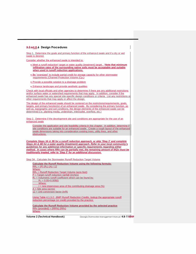
3.2.64.8.6 Design Procedures Step 1. Determine the goals and primary function of the enhanced swale and if a dry or wet swale is desired.
Consider whether the enhanced swale is intended to:
Meet a runoff reduction* target or water quality (treatment) target. *Note that minimum infiltration rates of the surrounding native soils must be acceptable and suitable when used in runoff reduction applications.
Be “oversized” to include partial credit for storage capacity for other stormwater requirements (Channel Protection Volume (Cpv)
Provide a possible solution to a drainage problem
Enhance landscape and provide aesthetic qualities
Check with local officials and other agencies to determine if there are any additional restrictions and/or surface water or watershed requirements that may apply. In addition, consider if the enhanced swale has any special site-specific design conditions or criteria. List any restrictions or other requirements that may apply or affect the design.
The design of the enhanced swale should be centered on the restrictions/requirements, goals, targets, and primary function(s) of an enhanced swale. By considering the primary function, as well as, topographic and soil conditions, the design elements of the enhanced swale can be determined (i.e. planting media, underdrain, inlet/outlet, overflow, etc.)
Step 2. Determine if the development site and conditions are appropriate for the use of an enhanced swale
Consider the application and site feasibility criteria in this chapter. In addition, determine if site conditions are suitable for an enhanced swale. Create a rough layout of the enhanced swale dimensions taking into consideration existing trees, utility lines, and other obstructions.
Complete Steps 3A & 3B for a runoff reduction approach, or skip ‘Step 3’ and complete Steps 4A & 4B for a water quality (treatment) approach. Refer to your local community’s guidelines for any additional information or specific requirements regarding either method. In cases where RRv can be partially met, the remaining amount of WQv must be traditionally treated, refer to ‘Step 5’ for an additional discussion.
Step 3A. Calculate the Stormwater Runoff Reduction Target Volume
Calculate the Runoff Reduction Volume using the following formula: RRV = (P) (RV) (A) / 12 Where: RRV = Runoff Reduction Target Volume (acre-feet) P = Target runoff reduction rainfall (inches) RV = Volumetric runoff coefficient which can be found by: RV = 0.05+0.009(I) Where: I = new impervious area of the contributing drainage area (%) A = Site area (acres) 12 = Unit conversion factor (in/ft) Using Table 4.1.3-2 - BMP Runoff Reduction Credits, lookup the appropriate runoff reduction percentage (or credit) provided by the practice: Calculate the Runoff Reduction Volume provided by the selected practice RRv (provided) = (RR%) (RRv) Where:
3.24.8-1290 Georgia Stormwater Management Manual Volume 2 (Technical Handbook)
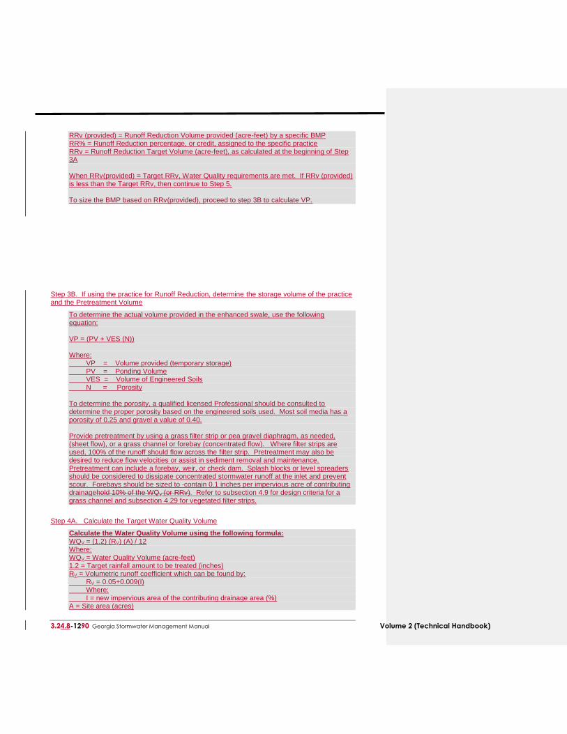
RRv (provided) = Runoff Reduction Volume provided (acre-feet) by a specific BMP RR% = Runoff Reduction percentage, or credit, assigned to the specific practice RRv = Runoff Reduction Target Volume (acre-feet), as calculated at the beginning of Step 3A When RRv(provided) = Target RRv, Water Quality requirements are met. If RRv (provided) is less than the Target RRv, then continue to Step 5. To size the BMP based on RRv(provided), proceed to step 3B to calculate VP.
Step 3B. If using the practice for Runoff Reduction, determine the storage volume of the practice and the Pretreatment Volume
To determine the actual volume provided in the enhanced swale, use the following equation: VP = (PV + VES (N)) Where: VP = Volume provided (temporary storage) PV = Ponding Volume VES = Volume of Engineered Soils N = Porosity To determine the porosity, a qualified licensed Professional should be consulted to determine the proper porosity based on the engineered soils used. Most soil media has a porosity of 0.25 and gravel a value of 0.40. Provide pretreatment by using a grass filter strip or pea gravel diaphragm, as needed, (sheet flow), or a grass channel or forebay (concentrated flow). Where filter strips are used, 100% of the runoff should flow across the filter strip. Pretreatment may also be desired to reduce flow velocities or assist in sediment removal and maintenance. Pretreatment can include a forebay, weir, or check dam. Splash blocks or level spreaders should be considered to dissipate concentrated stormwater runoff at the inlet and prevent scour. Forebays should be sized to contain 0.1 inches per impervious acre of contributing drainagehold 10% of the WQv (or RRv). Refer to subsection 4.9 for design criteria for a grass channel and subsection 4.29 for vegetated filter strips.
Step 4A. Calculate the Target Water Quality Volume
Calculate the Water Quality Volume using the following formula: WQV = (1.2) (RV) (A) / 12 Where: WQV = Water Quality Volume (acre-feet) 1.2 = Target rainfall amount to be treated (inches) RV = Volumetric runoff coefficient which can be found by: RV = 0.05+0.009(I) Where: I = new impervious area of the contributing drainage area (%) A = Site area (acres)
Volume 2 (Technical Handbook) Georgia Stormwater Management Manual 4.8-138989
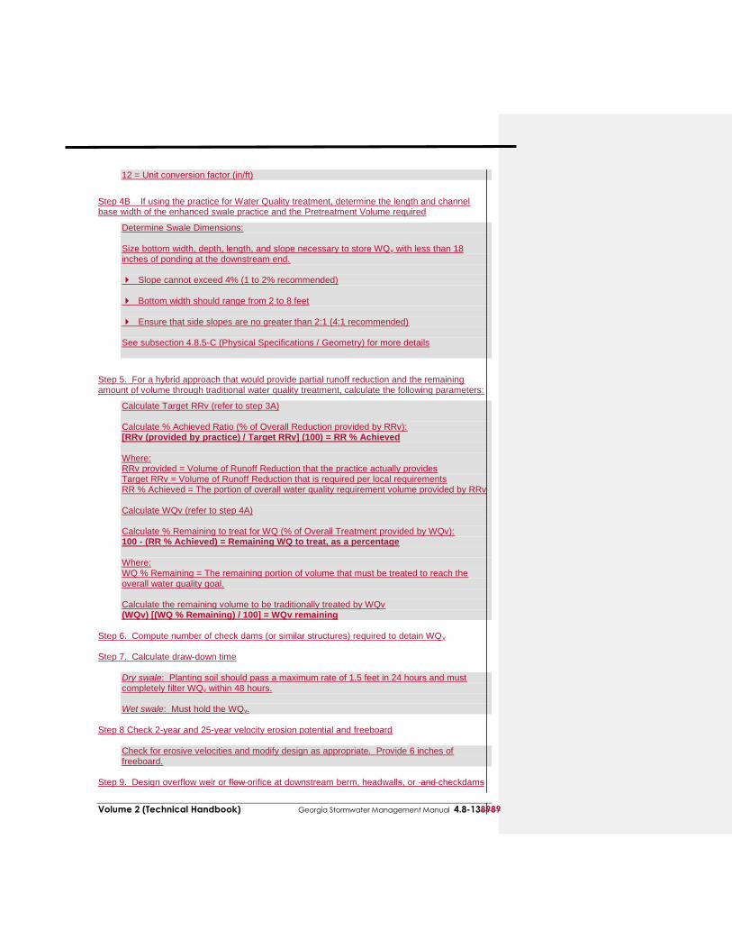
12 = Unit conversion factor (in/ft)
Step 4B If using the practice for Water Quality treatment, determine the length and channel base width of the enhanced swale practice and the Pretreatment Volume required
Determine Swale Dimensions: Size bottom width, depth, length, and slope necessary to store WQv with less than 18 inches of ponding at the downstream end. Slope cannot exceed 4% (1 to 2% recommended) Bottom width should range from 2 to 8 feet Ensure that side slopes are no greater than 2:1 (4:1 recommended) See subsection 4.8.5-C (Physical Specifications / Geometry) for more details
Step 5. For a hybrid approach that would provide partial runoff reduction and the remaining amount of volume through traditional water quality treatment, calculate the following parameters:
Calculate Target RRv (refer to step 3A) Calculate % Achieved Ratio (% of Overall Reduction provided by RRv): [RRv (provided by practice) / Target RRv] (100) = RR % Achieved Where: RRv provided = Volume of Runoff Reduction that the practice actually provides Target RRv = Volume of Runoff Reduction that is required per local requirements RR % Achieved = The portion of overall water quality requirement volume provided by RRv Calculate WQv (refer to step 4A) Calculate % Remaining to treat for WQ (% of Overall Treatment provided by WQv): 100 - (RR % Achieved) = Remaining WQ to treat, as a percentage Where: WQ % Remaining = The remaining portion of volume that must be treated to reach the overall water quality goal. Calculate the remaining volume to be traditionally treated by WQv (WQv) [(WQ % Remaining) / 100] = WQv remaining
Step 6. Compute number of check dams (or similar structures) required to detain WQv Step 7. Calculate draw-down time
Dry swale: Planting soil should pass a maximum rate of 1.5 feet in 24 hours and must completely filter WQv within 48 hours. Wet swale: Must hold the WQv.
Step 8 Check 2-year and 25-year velocity erosion potential and freeboard
Check for erosive velocities and modify design as appropriate. Provide 6 inches of freeboard.
Step 9. Design overflow weir or flow orifice at downstream berm, headwalls, or and checkdams
3.24.8-1490 Georgia Stormwater Management Manual Volume 2 (Technical Handbook)
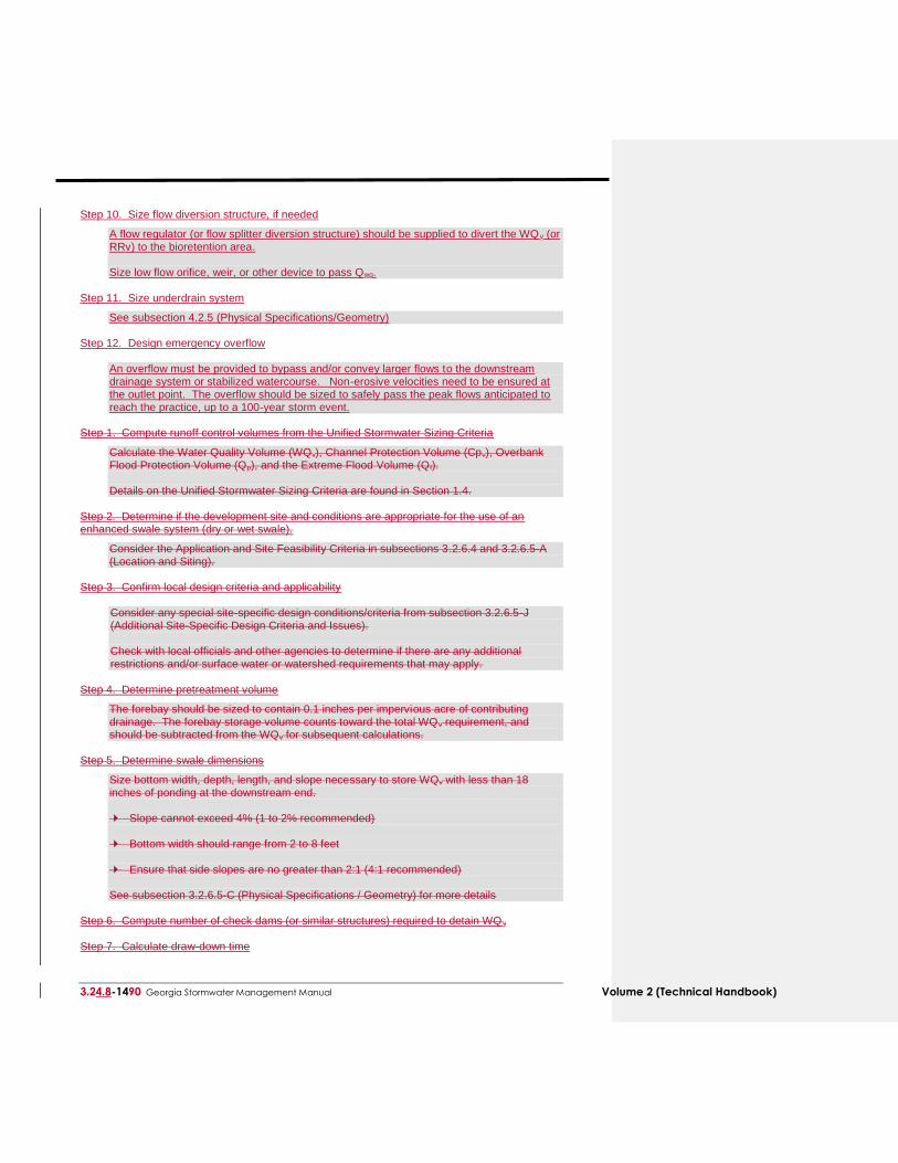
Step 10. Size flow diversion structure, if needed
A flow regulator (or flow splitter diversion structure) should be supplied to divert the WQ v (or RRv) to the bioretention area. Size low flow orifice, weir, or other device to pass Qwq.
Step 11. Size underdrain system
See subsection 4.2.5 (Physical Specifications/Geometry) Step 12. Design emergency overflow
An overflow must be provided to bypass and/or convey larger flows to the downstream drainage system or stabilized watercourse. Non-erosive velocities need to be ensured at the outlet point. The overflow should be sized to safely pass the peak flows anticipated to reach the practice, up to a 100-year storm event.
Step 1. Compute runoff control volumes from the Unified Stormwater Sizing Criteria
Calculate the Water Quality Volume (WQv), Channel Protection Volume (Cpv), Overbank Flood Protection Volume (Qp), and the Extreme Flood Volume (Qf). Details on the Unified Stormwater Sizing Criteria are found in Section 1.4.
Step 2. Determine if the development site and conditions are appropriate for the use of an enhanced swale system (dry or wet swale).
Consider the Application and Site Feasibility Criteria in subsections 3.2.6.4 and 3.2.6.5-A (Location and Siting).
Step 3. Confirm local design criteria and applicability
Consider any special site-specific design conditions/criteria from subsection 3.2.6.5-J (Additional Site-Specific Design Criteria and Issues). Check with local officials and other agencies to determine if there are any additional restrictions and/or surface water or watershed requirements that may apply.
Step 4. Determine pretreatment volume
The forebay should be sized to contain 0.1 inches per impervious acre of contributing drainage. The forebay storage volume counts toward the total WQv requirement, and should be subtracted from the WQv for subsequent calculations.
Step 5. Determine swale dimensions
Size bottom width, depth, length, and slope necessary to store WQv with less than 18 inches of ponding at the downstream end. Slope cannot exceed 4% (1 to 2% recommended) Bottom width should range from 2 to 8 feet Ensure that side slopes are no greater than 2:1 (4:1 recommended) See subsection 3.2.6.5-C (Physical Specifications / Geometry) for more details
Step 6. Compute number of check dams (or similar structures) required to detain WQ v Step 7. Calculate draw-down time

Volume 2 (Technical Handbook) Georgia Stormwater Management Manual 4.8-158989
Dry swale: Planting soil should pass a maximum rate of 1.5 feet in 24 hours and must completely filter WQv within 48 hours. Wet swale: Must hold the WQv.
Step 8. Check 2-year and 25-year velocity erosion potential and freeboard
Check for erosive velocities and modify design as appropriate. Provide 6 inches of freeboard.
Step 9. Design low flow orifice at downstream headwalls and checkdams
Design orifice to pass WQv in 6 hours. Use Orifice equation.

3.24.8-1690 Georgia Stormwater Management Manual Volume 2 (Technical Handbook)
Step 1013. Design inlets, sediment forebay(s), and underdrain system (dry swale)
See subsection 3.2.64.8.5-D through H for more details. Step 141. Prepare Vegetation and Landscaping Plan
A landscaping plan for a dry or wet swale should be prepared to indicate how the enhanced swale system will be stabilized and established with vegetation. See subsection 3.2.64.8.5-I (Landscaping) and Appendix F D for more details.
See Appendix DC-5 for an Enhanced Swale Design Example
3.2.64.8.7 Inspection and Maintenance Requirements
All best management practices require proper maintenance. Without proper maintenance, BMPs will
not function as originally designed and may cease to function altogether. The design of all BMPs
includes considerations for maintenance and maintenance access. For additional information on
inspection and maintenance requirements, see Appendix XX. Regular inspection and maintenance is critical to the effective operation of a bioslope as designed. Maintenance responsibility for a bioslope should be vested with a responsible authority by means of a legally binding and enforceable maintenance agreement that is executed as a condition of plan approval.
Table 3.2.64.8-1 Typical Maintenance Activities for Enhanced Swales (Source: WMI, 1997; Pitt, 1997)
Activity
Schedule
For dry swales, mow grass to maintain a height of 4 to 6 inches. Remove grass clippings.
As needed (frequent/seasonally)
Inspect grass along side slopes for erosion and formation of rills or gullies and correct.
Remove trash and debris accumulated in the inflow forebay.
Inspect and correct erosion problems in the sand/soil bed of dry swales.
Based on inspection, plant an alternative grass species if the original grass cover has not been successfully established.
Replant wetland species (for wet swale) if not sufficiently established.
Inspect pea gravel diaphragm for clogging and correct the problem.
Annually (Semi-annually the first
year)
Roto-till or cultivate the surface of the sand/soilengineered soil bed of dry swales if the swale does not draw down within 48 hours.
Remove sediment build-up within the bottom of the swale once it has accumulated to 25% of the original design volume.
As needed
All best management practices require proper maintenance. Without proper maintenance, BMPs
will not function as originally designed and may cease to function altogether. The design of all
BMPs includes considerations for maintenance and maintenance access. For additional
information on inspection and maintenance requirements, see Appendix XX.

Volume 2 (Technical Handbook) Georgia Stormwater Management Manual 4.8-178989
Regular inspection and maintenance is critical to the effective operation of an enhanced swale as designed. Maintenance responsibility for an enhanced swale should be vested with a responsible authority by means of a legally binding and
enforceable maintenance agreement that is executed as a condition of plan approval.
3.24.8-1890 Georgia Stormwater Management Manual Volume 2 (Technical Handbook)
3.2.64.8.8 Example Schematics
Figure 3.2.64.8-2 Schematic of Dry Swale
(Source: Center for Watershed Protection)
Volume 2 (Technical Handbook) Georgia Stormwater Management Manual 4.8-198989
Figure 3.2.64.8-3 Schematic of Wet Swale
(Source: Center for Watershed Protection)
3.24.8-2090 Georgia Stormwater Management Manual Volume 2 (Technical Handbook)
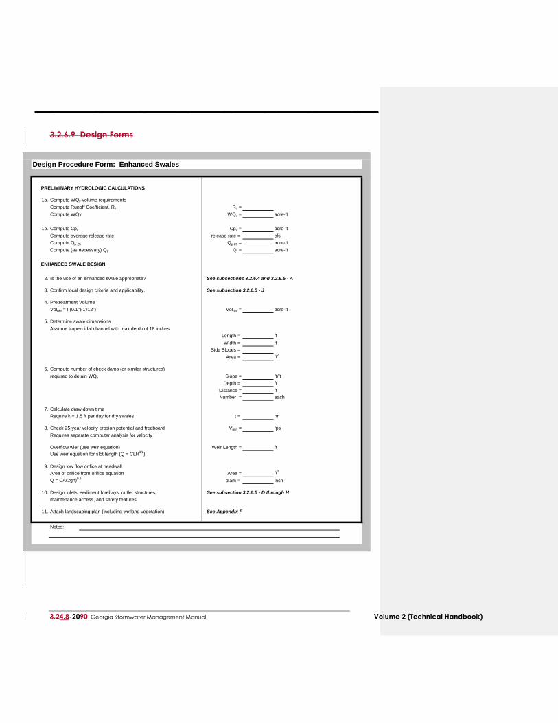
3.2.6.9 Design Forms
Design Procedure Form: Enhanced Swales
PRELIMINARY HYDROLOGIC CALCULATIONS
1a. Compute WQv volume requirements
Compute Runoff Coefficient, Rv Rv =
Compute WQv WQv = acre-ft
1b. Compute Cpv Cpv = acre-ft
Compute average release rate release rate = cfs
Compute Qp-25 Qp-25 = acre-ft
Compute (as necessary) Qf Qf = acre-ft
ENHANCED SWALE DESIGN
2. Is the use of an enhanced swale appropriate? See subsections 3.2.6.4 and 3.2.6.5 - A
3. Confirm local design criteria and applicability. See subsection 3.2.6.5 - J
4. Pretreatment Volume
Volpre = I (0.1")(1'/12") Volpre = acre-ft
5. Determine swale dimensions
Assume trapezoidal channel with max depth of 18 inches
Length = ft
Width = ft
Side Slopes =
Area = ft2
6. Compute number of check dams (or similar structures)
required to detain WQv Slope = ft/ft
Depth = ft
Distance = ft
Number = each
7. Calculate draw-down time
Require k = 1.5 ft per day for dry swales t = hr
8. Check 25-year velocity erosion potential and freeboard Vmin = fps
Requires separate computer analysis for velocity
Overflow wier (use weir equation) Weir Length = ft
Use weir equation for slot length (Q = CLH3/2
)
9. Design low flow orifice at headwall
Area of orifice from orifice equation Area = ft2
Q = CA(2gh)0.5
diam = inch
10. Design inlets, sediment forebays, outlet structures, See subsection 3.2.6.5 - D through H
maintenance access, and safety features.
11. Attach landscaping plan (including wetland vegetation) See Appendix F
Notes:

Volume 2 (Technical Handbook) Georgia Stormwater Management Manual 4.8-218989
This page left intentionally blank
Related Documents