JICA PREPARATORY SURVEY ON GREATER CAIRO METRO LINE NO. 4 Final Report - Volume 3 4-151 4.6.4 Study of the Shield TBM (1): Comparison between Single Track Double Tunnel (STDT) and Double Track Single Tunnel (DTST) The tunnel section of the metro will be constructed by the shield TBM. For the construction with two tracks, there are two alternatives: the Single Track Double Tunnel (STDT) and the Double Track Single Tunnel (DTST). According to the condition of land use of the ground surface, the most suitable alternative has been selected in Japan. In the case of the STDT, an isolation distance between two tunnels is necessary to avoid interference of excavation between tunnels. The isolation distance between the two tunnels was basically 1.0 D (D is excavation diameter). The STDT needs a wider right of way for construction. Therefore, the DTST was well used in the past in conditions where the existing road above the metro was narrow and land use at ground level was limited. However, the required isolation distance between two tunnels has been reduced in recent years thanks to the development of tunnel excavation technology. Consequently, the right of way for construction has been narrowed and the use of the STDT is becoming dominant these days in Japan because it is more economical and convenient. In the following sections, the main methods of economical construction and convenience are indicated. (1) Cross Sectional Area and Excavation Volume The excavation sectional area of STDT (75.84 m 2 ) is smaller than that of DTST (86.55 m 2 ). The total excavation volume of the DTST is approximately 123,000 m 3 , which is larger than that of the STDT. The excavation volume is the most important factor in the total cost. (2) Volume of Concrete The concrete volume for the segmental lining is almost equal in both cases. However, the volume of the lean concrete which fills the invert area under the track is different. There are many void spaces in the ceiling and under the track in DTST because the construction gauge and required space for two tracks, which are located in parallel in the tunnel, are of low profile. Thus, it is necessary to use much material to fill the invert area in the DTST. The Invert area of DTST is 5.0 times larger than that of STDT. Figure 4-109 Invert Area of Cross Section Large area of Invert Small area of Invert Source: JICA Study Team

Welcome message from author
This document is posted to help you gain knowledge. Please leave a comment to let me know what you think about it! Share it to your friends and learn new things together.
Transcript

JICA PREPARATORY SURVEY ON GREATER CAIRO METRO LINE NO. 4
Final Report - Volume 3 4-151
4.6.4 Study of the Shield TBM (1): Comparison between Single Track Double Tunnel (STDT) and Double Track Single Tunnel (DTST)
The tunnel section of the metro will be constructed by the shield TBM. For the
construction with two tracks, there are two alternatives: the Single Track Double Tunnel
(STDT) and the Double Track Single Tunnel (DTST). According to the condition of land
use of the ground surface, the most suitable alternative has been selected in Japan. In
the case of the STDT, an isolation distance between two tunnels is necessary to avoid
interference of excavation between tunnels. The isolation distance between the two
tunnels was basically 1.0 D (D is excavation diameter). The STDT needs a wider right of
way for construction. Therefore, the DTST was well used in the past in conditions where the
existing road above the metro was narrow and land use at ground level was limited.
However, the required isolation distance between two tunnels has been reduced in recent
years thanks to the development of tunnel excavation technology. Consequently, the right
of way for construction has been narrowed and the use of the STDT is becoming dominant
these days in Japan because it is more economical and convenient. In the following
sections, the main methods of economical construction and convenience are indicated.
(1) Cross Sectional Area and Excavation Volume
The excavation sectional area of STDT (75.84 m2) is smaller than that of DTST (86.55 m2).
The total excavation volume of the DTST is approximately 123,000 m3, which is larger than
that of the STDT. The excavation volume is the most important factor in the total cost.
(2) Volume of Concrete
The concrete volume for the segmental lining is almost equal in both cases. However, the
volume of the lean concrete which fills the invert area under the track is different. There
are many void spaces in the ceiling and under the track in DTST because the construction
gauge and required space for two tracks, which are located in parallel in the tunnel, are of
low profile. Thus, it is necessary to use much material to fill the invert area in the DTST.
The Invert area of DTST is 5.0 times larger than that of STDT.
Figure 4-109 Invert Area of Cross Section
Large area of Invert Small area of Invert
Source: JICA Study Team

JICA PREPARATORY SURVEY ON GREATER CAIRO METRO LINE NO. 4
Final Report - Volume 3 4-152
(3) Cost of the Shield TBM
Material cost represents a large proportion of the total cost of the shield TBM. The cost of
the shield TBM is closely related to its weight. The weight of the typical Earth Pressure
Balanced Shield (EPBS) TBM is shown in Figure 4-110. The weight of each machine of
STDT is approximately 400 tonnes (Outer Diameter of TBM = 6.95 m) and the total weight
of the machine is about 800 tonnes. On the other hand, the weight of DTST is
approximately 1200 tonnes (Outer Diameter of TBM = 10.5 m). The weight of DTST is
about 1.5 times heavier than that of STDT. Therefore, the cost of DTST is consequently
more expensive than that of STDT. In fact, 20-30% extra cost is usually required for the
machine cost in the case of DTST.
Figure 4-110 Diameter-Weight Relationship of the EPBS TBM
(4) Required Overburden at Nile River Crossing
It is important to secure enough overburden under the river bed to prevent the flotation of
the tunnel. The required overburden above the tunnel is basically 1.0 D (D is the excavation
diameter of the tunnel). As shown in Figure 4-111, STDT can be located at shallower
depths than DTST. At the passing point of the Nile River, it is anticipated that the depth of
the Nile River is 6 m or deeper. Therefore, the vertical alignment becomes very deep at the
Nile River crossing. This is constrained and the major control points of the vertical
alignment and depth of the stations, which are located in the vicinity of the Nile River, are
influenced. It is highly preferable to design the tunnel location to be as shallow as possible.
STDT has many advantages for the vertical alignment design.
Weight of EPBS TBM
0
200
400
600
800
1000
1200
1400
1600
0 1 2 3 4 5 6 7 8 9 10 11 12
Outer Diameter of EPBS TBM (m)
Wei
ght o
f EPB
S TB
M (t
)
Source: Shield Tunnelling Association of Japan

JICA PREPARATORY SURVEY ON GREATER CAIRO METRO LINE NO. 4
Final Report - Volume 3 4-153
Figure 4-111 Required Overburden at Nile River Crossing
(5) Ground Surface Settlement and Neighbouring Construction
The scale of ground deformation and ground surface settlement is proportional to the size
of tunnel. Therefore, the impact on the ground surface settlement and existing structures in
the vicinity of tunnel would be minimized if STDT is applied.
In addition, STDT can change the location of two tunnels flexibly from horizontal to vertical.
It is possible for STDT to avoid existing structures and pass narrow spaces. In some
areas, the foundation/piles of existing structures are closely situated and the space
between them is very narrow. STDT can provide less impact to the surrounding
environment.
Figure 4-112 Tunnel in the Vicinity of Existing Structures (Left: STDT, Right: DTST)
Nile River
6.8m
6.8m
10.3m
10.3m
Source: JICA Study Team
10m
Outer Diameter
of Shield TBM
Approx. 7m
El-GizaFlyover
Building
Outer Diameter
of Shield TBM
Approx. 10.5m
El-GizaFlyover
Building
10m
Source: JICA Study Team

JICA PREPARATORY SURVEY ON GREATER CAIRO METRO LINE NO. 4
Final Report - Volume 3 4-154
(6) Station Type (Island Platform and Side Platform) and Station Depth
The island platform is more convenient and comfortable for passengers than the side
platform. STDT can connect the island platform without shifting the horizontal alignment
and widening the station. Therefore, the island platform is widely used for STDT.
If DTST connects the island platform, the diversion of the horizontal alignment and
widening of the station are required at the transition section between tunnel and station.
As a result, the station tends to be more elongated and wider. Therefore, the side platform
is usually used for DTST.
In addition, the track level of DTST, as well as the platform level, becomes deeper due to
the large diameter of tunnel. Therefore, to enhance the service level for the passengers,
the island platform with STDT is more preferable.
(7) Ventilation in Tunnel
The metro requires a ventilation system to exchange the air in the tunnel, which is heated
by the train operation. The traffic flow in the STDT is unidirectional and the air always runs
in same direction. In addition, the piston effect of the train operation is helpful for ventilation
and the operation cost of ventilation becomes economical. Intermediate ventilation shafts
are usually not needed because of the high efficiency of ventilation.
On the other hand, the traffic flow in the DTST is bidirectional and the air flow in tunnel is
counterbalanced (see Figure 4-113). In addition, the intermediate ventilation shaft is
required to exhaust air due to the poor efficiency of ventilation. The construction cost and
operational cost will be increased very much in the case of the DTST.
Figure 4-113 Air Flow and Traffic Flow in Tunnel
Single Track Double Tunnel Double Track Single Tunnel
Source: JICA Study Team

JICA PREPARATORY SURVEY ON GREATER CAIRO METRO LINE NO. 4
Final Report - Volume 3 4-155
(8) Recommendation
As described above, the STDT has many advantages in construction, environment, cost
and operation. The application of the STDT is increasing all over the world, including
Europe. It is recommended to use the STDT for Metro Line 4. The comparison between
the STDT and the DTST is summarized in Table 4-42.
Figure 4-114 Photo of the STDT for Metro
Yurakucho Line, Tokyo, Japan Source: JICA Study Team, 2008
Cityringen, Copenhagen, Denmark Source: T&T International, July, 2008
Line B1 of Rome Metro, Rome, Italy Source: T&T International, March, 2009
Line 4, Beijing, China Source: T&T International, May, 2009

JICA PREPARATORY SURVEY ON GREATER CAIRO METRO LINE NO. 4
Final Report - Volume 3 4-156
Table 4-42 Comparison between the Single Track Double Tunnel and the Double Track Single Tunnel
Typical Tunnel Cross Section
Tunnel Outer Diameter Do=6.8m x 2tube 1 Do=10.3m×1tube 1.5
Shield Outer Diameter Ds=6.95m x 2 set 1 Ds=10.5m×1set 1.5
Width of Structure W=6.8m(vertical)to15.9 m (horizontal) 1.0~2.3 W=10.3m 1.5
Excavation Sectional Area A=75.84m2 1 A=86.55m2 1.14
Segment Sectional Area A=12.25m2 1 A=12.43m2 1.01
Required Overburdenat River Bed
6.8m(1.0・D) 1 10.3m(1.0・D) 1.5
Settlement of Surface 4mm(1.0・D Overburden ) 1 11mm(1.0・D Overburden) 2.8
Isolation distance to Flyoverstructure
about 0.5m(vertical) contact with structure
Invert Concrete Area 2.2m2 1 12.0m2 5.5
Disposal soil volume(L=11.5km)
872,160m3 1 995,352m3 1.14
Cost (per km) about 20 Million USD 1 about 22 Million USD 1.14
Platform Island Platform (High Service Level) Side Platform
Tunnel Ventilation Longitudinal (Economical) Concentrated Exhaust (Expensive)
Single Track Double Tunnel (STDT) Double Track Single Tunnel (DTST)
(STDT) (DTT)
Source: JICA Study Team
JICA PREPARATORY SURVEY ON GREATER CAIRO METRO LINE NO. 4
Final Report - Volume 3 4-157
4.6.5 Study of the Shield TBM (2): Comparison between Earth Pressure Balanced Shield (EPBS) TBM and Slurry Shield TBM
(1) Comparison and Recommendation on the Shield TBM
The Slurry Shield TBM has been used for many projects in Greater Cairo. On the
other hand, as of 2009, the EPBS has never been used for any project. The
comparison between EPBS TBM and Slurry Shield TBM is carried out to
determine a suitable method for the project while taking into account the
geological and congested city conditions in the project area. The comparison
study is summarized in Table 4-43.
It is recommended to use the EPBS TBM for the project. The introduction and
study of the EPBS is described in clause 4.6.6. The decisive factors in selecting
the EPBS TBM are as follows:
Safe Construction
The sand stratum of the project area is collapsible and application of the EPBS is
preferable for the stability of the cutting face in that condition.
Construction Yard
The use of Slurry Shield TBM will require a larger construction yard due to the
required space for slurry and separation plants.
Cost
The total cost for EPBS TBM is more economical than that of Slurry Shield TBM.

JICA PREPARATORY SURVEY ON GREATER CAIRO METRO LINE NO. 4
Final Report - Volume 3 4-158
Table 4-43 Comparison between the EPBS TBM and the Slurry Shield TBM
○ ○
◎ △
○ △
○ △
○ △
○ ○
○ △
○ ◎
○ △
○ ○
○ △
Note: ◎Excellent, ○Good, △Fair
Cost∙ Total cost of the EPBS TBM is generally more economical than that of the Slurry Shield TBM because of less additive use, smallerconstruction yard and smaller noise countermeasure.
∙ Total cost of the Slurry Shield TBM is generally more expensive than that of the EPBS TBM because of larger construction yardand countermeasure for large noise of plant.
EvaluationThe adoption of the EPBS TBM is yearly increasing all over the world. Especially, more than 70% of the shield TBM is the EPBS TBM in Japan as following reasons.① Total cost of the EPBS TBM is lower than that of the Slurry Shield TBM. ② The EPBS TBM was invented in Japan about 35 years ago and has been developed and matured under various geological condition.Note: The EPBS TBM and Slurry Shield TBM could be both applied to the various geological condition. The selection of the machine should be totally evaluated and determined by the geological condition, situation and location of construction site.
Launch Shaft ∙ The plant equipment is smaller and noise from the plant is also smaller.∙ The slurry plant equipment becomes larger and the noise and the vibration of the slurry processing equipment (vibrating screen)are also larger. Soundproofing and the vibration insulation measures are necessary.
Driving Speed ∙ It is assumed that driving speed of the shield is about 250m/month to 300m/month. ∙ It is assumed that driving speed of the shield is about 250m/month to 300m/month.
ShallowOverburden
∙ The specific gravity of the muddy soil is about 1.7 to 2.0 as same as the natural ground. Therefore, it is possible to balance both atcrown and bottom between the earth pressure of ground (including water pressure) and design earth pressure at bulkhead .Consequently, it is possible to excavate under shallow overburden (0.5D D: outer diameter of the TBM).
∙ The specific gravity of slurry is 1.1 to1.2 and lighter than that of the ground. Therefore, if the slurry pressure is balanced at thebottom of TBM under the shallow overburden condition, the slurry pressure at crown is excessive to the earth pressure of theground (including water pressure). There is possibility that the slurry is escaped and blown out in shallow overburden (0.5 D D:outer diameter of the shield)
High WaterPressure
∙ It is possible to excavate and drive with suitable control of the muddy soil condition in excavation chamber and water stoppagesystem of screw conveyor even under high water pressure of 0.45Mpa. Moreover, it is safer if the secondary screw conveyor is
li d
∙ Since the slurry system is the closed circuit, the TBM could excavate and drive normally even under the high water pressure of0.45MPa.
・Boulder: The boulder could be continuously discharged through the 750mm diameter screw conveyor if boulder is450mm×250mm dimension or smaller.
・Boulder: It is necessary to break the boulder to size of 1/3 or less of the discharge pipe (250mm diameter) by the crasher.
・Limestone: It is necessary to attach the roller cutter on the cutting head. ・Limestone: It is necessary to attach the roller cutter on the cutting head.
Control ofExcavation
1. The Earth Pressure at Cutting Face: The amount of the discharging soil is controlled by measuring the earth pressure atbulkhead, the speed of the push jack and the rotational speed of the screw conveyer.2. Amount of Discharging soil:The flow meter and the RI (Radio Isotope) densimeter, etc. are installed in the soil exhaust. Theamount of the discharging soil is measured and managed simultaneously.3. Properties of Muddy soil:Control of discharging soil density, water content, the slump, quality and quantity of the additive.
1. The Slurry Pressure at Cutting Face: The slurry pressure is measured with the water pressure gauge installed at the bulkheadand it is controlled by the slurry feed/discharge pump.2. Amount of discharging soil: The flow meter and the densimeter are installed in slurry discharge pipeline. Flow and the density ofslurry are measured and analyzed and the amount of soil as dry condition is calculated and is fed back to the control.3. Properties of slurry:The specific gravity and the viscosity etc. of the slurry are managed.
GroundCondition
∙ Clay: In case of soft clay, the additive is not required. Even hard clayey material, it is easily transmuted to the muddy soil if wateror small additive is added. Consequently, the cost for the additive is quite economical.
∙ Clay: Large plant is required to separate the muck and slurry according to environmental law (Japan). Cost becomes expensive.
∙Sand: The excavated fine and midium sand could be transmuted into the muddy soil by the additive material. In case of the sandwhich the uniformity coefficient is under 6,the cutting face can be stabilized by muddy soil. The muddy soil can smoothlydischarge and transfar to the starting base by the belt conveyer.
∙ Sand : When the uniformity coefficient is under 6,and soil particle of under 74μof sand is under 8 % , the stability of the cuttingface is difficult in the slurry shield.The vibration screen and cyclone are required to classify the sandy muck by size andcountermeasure for noise and vibration is required.
∙Sand and gravel: as same as sandy soil. ・Sand and gravel: As same as sandy soil. In addition, if the size of the gravel is 1/3 or bigger than the diameter of discharge pipe(φ250mm) , the crusher for the gravel is required.
Outline of theMachine
MainSpecification
∙Shield outer diameter: φ6.95m∙Jack thrust power: 2,000kN×21 pcs=42,000kN∙Screw conveyer diameter: φ750mm
∙Cutter torque: 5,700 kN ∙ m∙Cutter rotation speed: 0.8 rpm∙Cutter power: 481kw
・Shield outer diameter: φ6.95m・Shield jack thrust power: 2,000kN×21 pcs=42,000kN・Slurry removal pipe diameter: φ250 mm
・Cutter torque: 4,700 kN∙ m・Cutter rotation speed: 0.8 rpm・Cutter power: 407 kw
Item Earth Pressure Balanced Shield TBM Slurry Pressure Balanced Shield TBM
Condition∙ Segment outer diameter: φ6.8m∙ Excavation section area: 37.9 ㎡∙ Overburden:15~45m
∙ Shield outer diameter: φ6.95m∙ Segment section area: 6.12 ㎡∙ Ground condition: Clay, sand, gravel, limestone
Source: JICA Study Team

JICA PREPARATORY SURVEY ON GREATER CAIRO METRO LINE NO. 4
Final Report - Volume 3 4-159
4.6.6 Introduction and Study of EPBS TBM
The shield TBM has been developed to construct tunnels in soft ground condition of the city
area. In 1967, the first practical Slurry Shield TBM was developed in Japan. The
compressed air shield, which had been widely used, was replaced by the Slurry Shield
TBM and this technology spread throughout world. After the development of the Slurry
Shield TBM, the first advanced EPBS TBM was invented in 1974 in Japan to reduce the
total construction cost, the required space for ground level construction yard and
environmental impact.
In recent years, the use of EPBS TBM has prevailed over Slurry Shied TBM in Japan
because of lower construction cost and smaller construction yard at ground level. There
were 1187 constructions using Shield TBM in Japan from 1998 to 2007 and 70% of them
were done by the EPBS TBM (see Figure 4-115). The technology of the EPBS TBM is
introduced as follows:
Figure 4-115 Application of Different Shield TBM Types in Japan (1998-2007)
EPBS Slurry Semi Mechanical
EPBS (Conventional) Mechanical
Manual
Others Blind EPBS
835 70.8%
Slurry 308 26.1%
Semi Mechanical 11 0.9%
EPBS (Conventional), 9, 0.8%
Manual,1, 0.1% Others 10, 0.8%
Mechanical, 5, 0.4%
Source: Shield Tunnelling Association of Japan
Blind 0, 0.0%

JICA PREPARATORY SURVEY ON GREATER CAIRO METRO LINE NO. 4
Final Report - Volume 3 4-160
(1) Development and Practices of EPBS TBM
The EPBS TBM was invented in 1974 and has been developed in Japan. So far, there
have been more than 1400 construction practices by EPBS TBM in Japan and other
countries. This method can be applied in various ground conditions, such as clay, sand,
gravel, volcanic ash soil and mudstone.
The technology of the EPBS TBM has been developing and its application with large
diameter projects is increasing. The largest diameter of the EPBS TBM is approximately
15m, which was used for the M30 ring road tunnel in Madrid City, Spain. The large EPBS
TBM of 12 m diameter class is used for road tunnel projects in Japan and 7-10 m diameter
classes are widely used for subway construction.
Figure 4-116 EPBS TBM (Outer Diameter 6.24m)
(2) Principles of EPBS TBM
a) Principle of Stability at Cutting Fface
The principle of stability at the cutting face by EPBS TMB is as follows:
1) Making of Muddy Soil from Excavated Soil
The ground is excavated by the spoke type cutting head and the excavated muck
is simultaneously mixed with additive injection. The excavated soil and additive
material are mixed well by the mixing blade, which is located at the rear of the
cutting head. The mixed material has a unit weight equivalent to the ground and
becomes muddy soil, which has a characteristic of plastic flow and low
permeability.
Source: IHI Corporation

JICA PREPARATORY SURVEY ON GREATER CAIRO METRO LINE NO. 4
Final Report - Volume 3 4-161
2)Generation of Pressure at Bulk Head (in excavation chamber) and Stabilization
of Cutting Face
The excavation chamber and screw conveyor are filled with muddy soil. Then, the
muddy soil in the excavation chamber is pressurized by the push jack. The
generated earth pressure at the bulkhead balances and resists the earth pressure
at rest, as well as water pressure, thus, stabilizing the cutting face.
3)Excavation and Driving Control by Earth Pressure at Bulkhead
The cutting face is stabilized by the earth pressure at the bulkhead. The driving
speed of the push jack and rotation speed of the cutting head are adjusted and
controlled to stabilize the earth pressure at bulkhead.
Figure 4-117 Design Earth Pressure at Bulkhead and Outline of EPBS TBM
Earth Pressure Gauge Push Jack
Additive Injection Port EEAA
Cutter Head
Mixing Blade Earth Pressure at Bulk Head
Earth Pressure at Rest
Water Pressure Screw Conveyer Muddy Soil
in Excavation Chamber
Additive Injection Pipe
Source: Shield Tunnelling Association of Japan

JICA PREPARATORY SURVEY ON GREATER CAIRO METRO LINE NO. 4
Final Report - Volume 3 4-162
b) Plasticity Fluidizing of the Excavated Soil
As explained in the preceding section, it is necessary and important to make
muddy soil which has characteristics of plastic flow and low permeability.
The muddy soil, which is filled and pressurized in the excavation chamber, is
continuously fluidized in the chamber and exhausted to the screw conveyor. The
diameter of the screw conveyor is about 1/10 of the shield TBM and the muddy
soil is required to be deformed and be fluidized easily in the excavation chamber.
Figure 4-118 Deformation and fluidization of muddy soil in excavation chamber
c) Procedure of Plasticity Fluidizing of the Excavated Soil
The soft clayey soil is easily plasticized and fluidized by the excavation. On the
other hand, the sandy soil and sand with gravel would block the excavation
chamber due to the angle of internal friction if there is no additive injection used.
Therefore, it is important to have an additive injection and mix it well with the
mixing blade.
Figure 4-119 Image of Muddy soil in Excavation Chamber
Muddy Soil in Excavation Chamber
Screw Conveyor
Plastic Muddy Soil easily deforms and is fluidized.
Source: JICA Study Team
Pressure
Pressure
Pressure
Pressure
Additive
Additive
Soil Particle
Soil Particle
Source: JICA Study Team

JICA PREPARATORY SURVEY ON GREATER CAIRO METRO LINE NO. 4
Final Report - Volume 3 4-163
(3) Study of the Application of the EPBS TBM to Metro Line 4
a) Applicable Ground Condition
The EPBS TBM can be applied not only in clayey soil but also in sandy soil and
soil with gravel. Besides, it is possible to apply the EPBS TBM to the alternation
of these strata if an additive injection with an appropriate quality and content is
used in the excavation chamber.
1) Clayey Soil
If the water content exceeds the liquid limit in the soil, the additive injection is not
required. In other cases, the amount of the additive injection is determined by
the ratio of fine material (smaller than 0.074 mm).
2) Sandy Soil and Gravel
The EPBS TBM can be applied to sandy soil and gravel layer if a suitable
concentration of additive injection is applied. In accordance with the ratio of fine
material in sandy and gravel soil, the amount of additive injection is determined.
If more than 30% of fine material is included, additive injection is not required. In
case that the uniform coefficient (Cu=D60/D10*) of the ground is less than 5, the
ground condition is expected to be unstable and it is therefore necessary to
increase the additive injection.
The EPBS TBM can be applicable to the stratum with boulders (up to 450 mm x
250mm). Boulders can be mucked using the screw conveyor of 850mm diameter,
which equips the EPBS TBM of 7 m outer diameter class.
Note: D60 corresponds to the 60% finer in the particle size distribution and D10
corresponds to the 10% finer.
3) Alternation of clay, sand and gravel strata
In the same way as for the sandy and gravel layers, the EPBS TBM can be
applied to the alternation of strata and the amount of the additive injection is
determined by the content of the fine material.
b) Applicability to Shallow Overburden
There are many practices and experiences involving the application of the EPBS
TBMs to projects with shallow overburden. According to the application of the
appropriate control of earth pressure at bulkheads and use of advanced rapid
hardening backfill material for tail void, the ground surface settlement and
displacement of the neighbouring construction can be controlled within a few
millimetres.

JICA PREPARATORY SURVEY ON GREATER CAIRO METRO LINE NO. 4
Final Report - Volume 3 4-164
c) Applicability to River Crossing
There were experiences of river crossings using the EPBS TBM in Japan. The
most severe case was to cross the river in diluvium sandy strata with shallow
overburden of 4.4 m (0.6D, where D is the outer diameter of the shield tunnel).
The EPBS TBM can be used to cross the Nile River and other canals with suitable
overburden taking into consideration the floating during construction and after
completion of the tunnel.
d) Applicability to Neighboring Construction
Metro Line 4 is anticipated to pass in the vicinity of other existing structures.
Therefore, it is necessary to study the neighbouring construction between existing
structures and the shield TBM. There were similar and more severe experiences
in Japan that were constructed by the EPBS TBM. The EPBS TBM passed
under the piles of bridges and the distance between these structures was
sometimes just 1.5 m (0.2D). Besides, EPBS often crossed near existing tunnels
at a distance of 0.6 m or less.
e) Applicability to the Ground with High Water Pressure
As illustrated in Figure 4-117, the EPBS TBM stabilizes the cutting face by the
earth pressure at bulkhead, which is a bit higher than the pressure from the
ground (earth pressure at rest + water pressure) and drives forward. Even under
the condition of the high water pressure of 0.4 MPa, the underground water
cannot surge into the excavation chamber, enabling the EPBS TBM to drive safely.
There were many practices that involve thick overburden, which is 40 m or deeper.
According to these experiences and practices, the EPBS TBM can be applied to
the sand or gravel layer with high water pressure conditions in Metro Line 4.
f) Applicability to Long Distance Driving and Construction
Even if the Shield TBM is continuously driven more than 5 km before completion
of the intermediate vertical shaft (station), the long distance mucking from the
EPBS TBM can be easier with a continuous belt conveyor or muck car than with
the slurry liquid discharge from the Slurry Shield TBM, which requires more than
20 discharge pumps.
g) Disposal of Waste Soil
The mucked soil must be disposed carefully according to environmental
laws/decrees, thus, it is necessary to install a plant for its treatment. In the case
of the Slurry Shield TBM in Japan, it is necessary to locate a large plant which
separates slurry and muck. Furthermore, this plant creates loud noises when
slurry and muck are separated. On the other hand, the EPBS TBM does not
need such a large plant at the construction yard.

JICA PREPARATORY SURVEY ON GREATER CAIRO METRO LINE NO. 4
Final Report - Volume 3 4-165
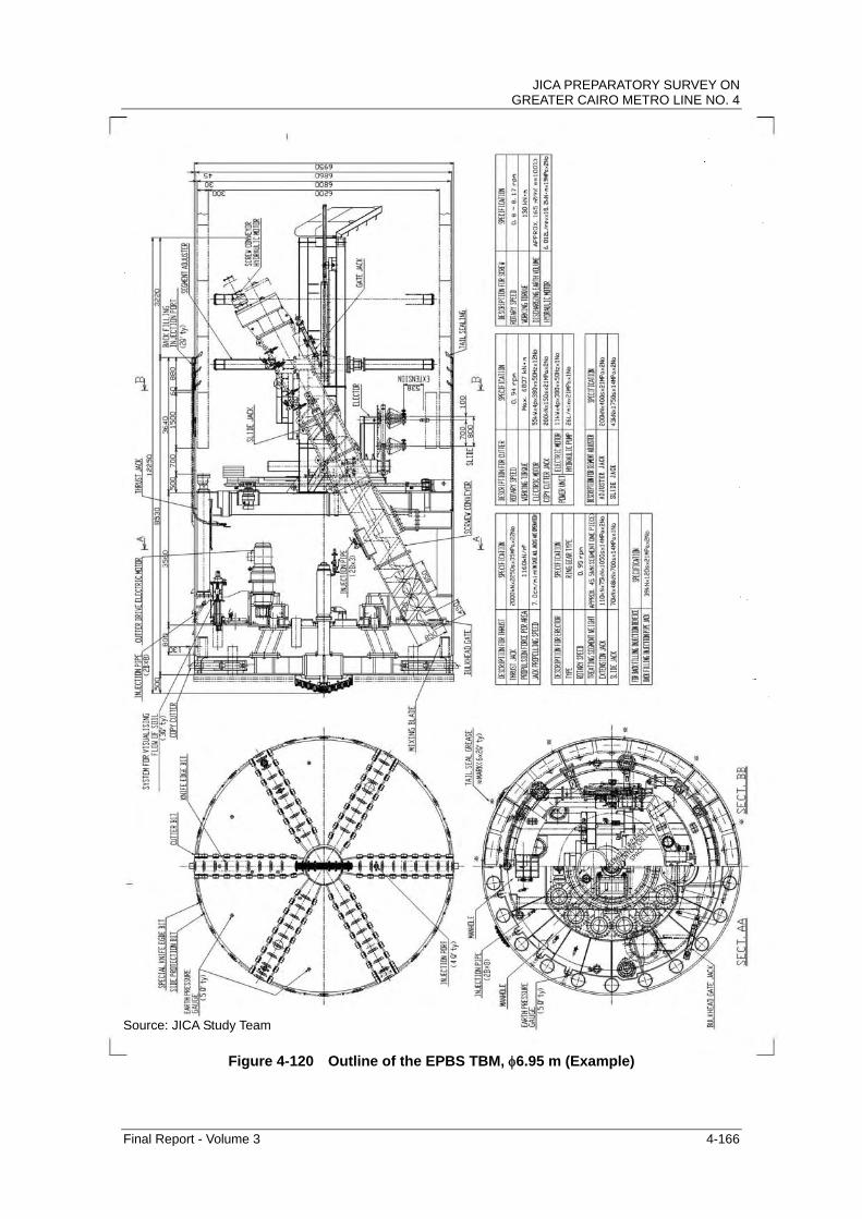
(4) Outline of EPBS TBM
The shield TBM is studied for the project. The general feature of the shield TBM is
tabulated in Table 4-44 and its outline is shown in Figure 4-120.
Table 4-44 General Features of the EPBS (6.95 m)
Item Specification Remarks Shield Outer Diameter φ6.95 m Stabilization of Cutting Face EPBS Type Cutter Torque 6,807KN·m (max) Cutter rpm 0.94 rpm Facility Thrust Force 44,000 KN
Advance Speed 3~3.5 cm/min. Average monthly advance of about 300m (main driving)
Screw Conveyor φ850 mm
For Advance Excavation
Precutting Bit
For Sandy Soil Teeth Bit Bit
For limestone Roller Bit
Source: JICA Study Team
JICA PREPARATORY SURVEY ON GREATER CAIRO METRO LINE NO. 4
Final Report - Volume 3 4-166
Source: JICA Study Team
Figure 4-120 Outline of the EPBS TBM, 6.95 m (Example)

JICA PREPARATORY SURVEY ON GREATER CAIRO METRO LINE NO. 4
Final Report - Volume 3 4-167
a) Excavation Mechanism for Sandy Soil and Rock
It is expected that the shield TBM will excavate and drive mainly in fine sandy to
medium sandy strata in the project. It is necessary to consider this condition for
the selection of cutter bits.
The cutter bits attached on the cutter head of the shield TBM are the fishtail bits as
the centre bit, the pre-cutting bit as the advance bit and the teeth bits as main bits.
As the combination of these bits, there are many practices in excavating FFU,
which is used at the launch and arrival shaft and improved soil by the jet mixing
column. Moreover, there is a practice of long drive construction which exceeds
5 km and the frequency of exchange of these bits is assumed to be once or twice
in every 5 km. In the area where limestone is expected (Station 12 to 14), roller
cutters will be considered.
Figure 4-121 Example of Bits on Cutter Head (Left: Pre-Cutting and Tooth Bits, Right: Roller Cutter and Tooth Bits)
b) Torque of the Cutter Head
The torque of the cutter head is proportional to the cube of the outer diameter of
the shield TBM and the empirical formula is “T=·D3”. Based on past
experiences and practices, the coefficient, ranges from 13 to 20 for sandy
ground. Thus, 4400-5000 kN-m is prepared for normal conditions and
6800-7000 kN-m as maximum.
c) Thrust Force
The thrust force of the shield TBM is approximately 1100-1200 kN/m2 based on
past experiences and practices. Therefore, the resulting thrust force required is
42,000-45,000 kN.
d) Control System of the Earth Pressure (Pressure at Bulkhead)
The bulkhead is equipped with about five pressure metres, and it should be
possible to exchange two of them, even during excavation.
Source: Japan Society of Civil Engineers

JICA PREPARATORY SURVEY ON GREATER CAIRO METRO LINE NO. 4
Final Report - Volume 3 4-168
e) Backfill Grouting
The backfill grouting is simultaneously carried out with excavation through the pipe
which is attached on the crown of the shield TBM. The backfill material is
composed of cementitious material (liquid A) and liquid grass (liquid B). These
materials are mixed just before casting to the tail void. The mixed backfill
material is plastic and hardens rapidly. Most of the constructions in Japan made
use of this material for shield tunnel construction, which proved to generate less
settlement and be watertight. The durability for long term use was also proved.
f) Mucking of the Excavated Soil
The mucking from the shield TBM is done by continuous belt conveyer. The
excavated material is carried by the belt conveyer to the shaft and lifted up to
ground level by the vertical belt conveyer. The belt conveyer is extended at an
interval of 300 m excavation. An image of the extension of the belt conveyer is
given in Figure 4-122
Figure 4-122 Image of the Extension of the Continuous Belt Conveyor
g) Disposal of Excavated Soil
The excavated material is mixed with an additive and becomes mud with plastic
fluidity. The mucked material is carried to the disposal area by dump truck and is
dried in the yard. After that, it will be filled in at a suitable disposal area.
Source: Kyushu Shinkansen Tagami Tunnel, Tunnel and Underground, Japan

JICA PREPARATORY SURVEY ON GREATER CAIRO METRO LINE NO. 4
Final Report - Volume 3 4-169
(5) Daily Monitoring and Control of EPBS TBM
The daily monitoring and control of the tunnel excavation is important for safe
construction. As for the daily monitoring and control of the EPBS TBM, the
following items will be planned and carried out:
a) Earth pressure in chamber
b) Plastic flow condition of muddy soil in chamber
c) Measurement of excavated soil and discharged soil
d) Measurement and control for injection pressure and amount of the backfill
material
e) Control of mix portion and amount of additive
f) Measurement and control of the cutter torque of the shield TBM
g) Control of thrust force of push jack on the shield TBM
a) Earth Pressure in Chamber
The earth pressure at bulkhead is continuously measured by multiple earth
pressure meters the bulkhead and the optimum earth pressure is obtained and
controlled by adjusting the speed of push jack and revolution of screw conveyor.
The earth pressure at bulkhead is controlled to be higher than the sum of active
earth pressure and water pressure and to be lower than the sum of passive earth
pressure and water pressure. The optimum earth pressure at bulkhead is
controlled to minimize ground settlement.
b) Plastic Flow Condition of Muddy Soil in Chamber
The plastic flow of muddy soil in chamber is controlled to be in a suitable condition
by adjusting the amount of additive injection and continuous monitoring of the
fluctuation of cutter torque. In addition, the muddy soil condition, which is
discharged through the screw conveyor, is confirmed and monitored by hand
touching and material watching. The water content and unit weight of the muddy
soil is frequently measured to know the change of the muddy soil condition.
c) Measurement of Excavated Soil and Discharged Soil
The volume of excavated soil is calculated as the product of cross sectional area
and driven speed of the shield TBM. In addition, the discharged soil through the
screw conveyor is continuously measured and compared with the amount from the

JICA PREPARATORY SURVEY ON GREATER CAIRO METRO LINE NO. 4
Final Report - Volume 3 4-170
calculated volume. The difference between the calculated and measured
volumes is fed back to the control and adjustment of the excavation. The volume,
weight and density of the discharged soil is measured and controlled by
densimeter, flow-meter, number of pumping and weight scale according to the
mucking delivery method (belt conveyor, pumped either through pipe or muck car).
d) Measurement and Control for Injection Pressure and Amount of the Backfill Material
The injection pressure and amount of backfill material for the tail void are
continuously monitored and controlled to minimize ground settlement.
e) Control of Mix Portion and Amount of Additive
The type and consistency are determined by the mix portion test according to the
actual soil condition. The amount of additive is controlled to make suitable
muddy soil according to the monitoring of cutter torque of the shield TBM.
f) Measurement and Control of the Cutter Torque of the Shield TBM
The cutter torque is controlled and adjusted according to the soil condition, driven
speed of the shield TBM and the amount of the additive.
g) Control of Thrust Force of Push Jack on the Shield TBM
The thrust force of the push jack on the shield TBM is controlled with accordance
with the earth pressure at bulkhead, driven speed and control of the direction.
The flow chart of the daily monitoring and control of the EPBS TBM is indicated in
the Figure 4-123.

JICA PREPARATORY SURVEY ON GREATER CAIRO METRO LINE NO. 4
Final Report - Volume 3 4-171
Figure 4-123 Flow chart of Control of the Cutting Face of the EPBS TBM

JICA PREPARATORY SURVEY ON GREATER CAIRO METRO LINE NO. 4
Final Report - Volume 3 4-172
4.6.7 Technical Study of the Shield TBM Construction
The shield TBM will pass under the congested central area of Greater Cairo City. It is
anticipated to pass in the vicinity of existing structures and their foundations/piles.
Therefore, the dilapidation survey of the existing structure is carried out to confirm the
deterioration of neighbouring structures. From the aspect of tunnel engineering, the
required countermeasures are assessed and studied. In addition, the shield TBM will pass
under the Nile River with shallow overburden and the floating of tunnel at crossing point is
also studied.
(1) Study of the Neighbouring Construction
The major technical point of the neighbouring construction is illustrated in Figure 4-124.
Each neighbouring construction is assessed and studied by the impact level, which is
determined by ground displacement analysis of the Finite Element Method (FEM).
According to the level of displacement of the ground, the impact level is classified into two
levels. The impact levels are defined as follows.
Level IT: the ground area where 5-10 mm displacement is expected.
Level IIT: the ground area where 5 mm or less displacement is expected.
No.155(-0k980m)
WaterSupplyBridge
No.12(0k297m)
El-NilFlyover
No.53(2k220m)El-GizaFlyover
No.56(2k220m)
El-RayTunnel
Trackof ENR
No.75(5k328m)
PedestrianTunnel
No.125(8k610m)New road
Bridge
No.127(8k759m)
RoadTunnel
No.134(9k500m)
CanalMansouria
Note: - No.***: Number of Structure in the dilapidation survey - (*k***m): Chanage
Figure 4-124 Major Neighboring Constructions

JICA PREPARATORY SURVEY ON GREATER CAIRO METRO LINE NO. 4
Final Report - Volume 3 4-173
a) No.12 El-Nile Flyover
The depth of the piles is unknown. It is therefore necessary to measure the depth
and confirm the isolation distance from the tunnel in the design stage. As
illustrated in Figure 4-125, there are possibilities that the bottom of the pile is
located in level IIT area and the pile point bearing will affect the segmental lining of
the tunnel. In this case, high stiffness segmental lining will be considered and
designed.
Figure 4-125 No. 12 El-Nile Flyover
b) No.53 El-Giza Flyover
The piers of the El-Giza Flyover are densely located and it is inevitable to pass in
the vicinity of piles of these piers. The location and depth of piles are unknown.
The tunnels are located vertically to avoid the piles but there is a possibility that
the isolation distance between tunnel and pile is 1.1 m. Therefore, it is necessary
to measure the location and depth of the piles and design the segmental lining
considering the influence of the point bearing of the pile, if the bottom of pile is
situated above the crown of tunnel.
El-Nil Flyover
Ic, IIc: Impact Level
7m
No.12(0k297m)
Source: JICA Study Team
Level IIT
Level IT

JICA PREPARATORY SURVEY ON GREATER CAIRO METRO LINE NO. 4
Final Report - Volume 3 4-174
Figure 4-126 No. 53 El-Giza Flyover
c) No.56 El-Ray Tunnel
The pile of the structure is not confirmed but it is assumed that the pile is relatively
short or does not exist because the structure is cut and cover tunnel. Therefore,
there will be no impact from tunnel excavation.
Figure 4-127 No. 56 El-Rat Flyover
d) No.75 Tunnel
Judging from the structural condition, it is assumed that the piles of No.75 tunnel
are non-existent. However, the overburden from the shield tunnel to No. 75
tunnel is less than 1.0D (D: Excavation diameter of the shield tunnel). The
El-Giza Flyover
Ic, IIc: Impact Level
7m
No.53(2k220m)
Source: JICA Study Team
Source: JICA Study Team
El-Ray Tunnel
Ic, IIc: Impact Level
7m
No.56(2k220m)

JICA PREPARATORY SURVEY ON GREATER CAIRO METRO LINE NO. 4
Final Report - Volume 3 4-175
ground displacement and surface settlement will be measured and the ground will
be improved by post injection after the passing of the shield TBM if necessary.
Figure 4-128 No. 75 Tunnel
e) No.125 Bridge
Although the depth of the pile is not confirmed, it is anticipated that the pile is
closely located in the vicinity of tunnel (about 3 m). Therefore, it is necessary to
measure the location and depth of the piles and to design the segmental lining
considering the influence of the point bearing of pile, if the bottom of pile is
situated above the crown of tunnel.
Figure 4-129 No.125 Tunnel
f) No.127 Road Underpass
It is assumed that the minimum distance between the shield tunnel and the road
underpass is more than 1.0D. Therefore, there is no influence from the shield
TBM.
PedestrianTunnel
Ic, IIc: Impact Level
7m
No.75(5k328m)
Source: JICA Study Team
New Road Bridge
Ic, IIc: Impact Level
7m
No.125(8k610m)
Source: JICA Study Team

JICA PREPARATORY SURVEY ON GREATER CAIRO METRO LINE NO. 4
Final Report - Volume 3 4-176
Figure 4-130 No.127 Road underpass
g) No.155 Magra El-Eyoon (Water Supply Viaduct)
There is enough overburden above tunnel and the impact on the water supply
bridge is negligible.
Figure 4-131 No. 155 Magra El-Eyoon (Water Supply Viaduct)
Road Underpass
Ic, IIc: Impact Level
7m
No.127(8k759m)
Source: JICA Study Team
Water supply bridge
Ic, IIc: Impact Level
7m
No.155(-0k980m)
Source: JICA Study Team

JICA PREPARATORY SURVEY ON GREATER CAIRO METRO LINE NO. 4
Final Report - Volume 3 4-177
(2) Nile River Crossing (Study for Floating of Tunnel)
It is important to secure enough overburden under the river bed to prevent the
floating of the tunnel both during construction and operation. The required
overburden above the tunnel is basically 1.0D (D is the excavation diameter of the
tunnel). The sounding survey at the Nile River Crossing was carried out and the
cross sectional depth of the Nile River was surveyed. In addition, the historical
analysis of the fluctuation of the river bed was done with the data of year 1982 and
2003. The river bed of the Nile River has the tendency of sedimentation as
indicated in Figure 4-132. The deepest point of the Nile River is used for the
study for the floating of the tunnel. The floating of the tunnel is studied for the
condition of construction stage because the weight of the tunnel is lighter and is in
a more severe condition. The safety factor for the floating should be more than
1.03 for the construction stage and the result of the study is 1.47. Therefore, the
floating of the tunnel is prevented if the overburden is more than 1.0D.
As explained in the geological condition section, the uniformity coefficient of the
sandy stratum is very small and it is necessary to consider and study the
possibility of liquefaction in the next stage of the study.
Figure 4-132 Sound Survey and Historical Analysis of the River Bed at Nile River Crossing
Source: Nile River Survey Report, Nile Research Institute, 2009

JICA PREPARATORY SURVEY ON GREATER CAIRO METRO LINE NO. 4
Final Report - Volume 3 4-178
Figure 4-133 Model of the Study for the Floating of Tunnel at Nile River Crossing
Table 4-45 Comparison between the EPBS TBM and the Slurry Shield TBM
▽-6.5mRL
5.5m
▽6m (Deepest Point*1)
7.0m
Nile River
6.8m
Overburden
RL
Source: JICA Study Team
Source: JICA Study Team
Mark unit Value note
Input Ro m 3.400
H m 7.000 Overburden
Hw m 7.000
γ kN/m3 17.0
γ' kN/m3 7.0
γw kN/m3 10.0
γrc kN/m3 26.0 Segment (SG)
t m 0.300 thickness of SG
g kN/m2 7.800 γrc×t
Po kN/m2 0.000
Pi kN/m2 0.000
Output Fs - 1.472 Safety Factor
Evaluation OK Fs>1.0

JICA PREPARATORY SURVEY ON GREATER CAIRO METRO LINE NO. 4
Final Report - Volume 3 4-179
4.6.8 Tunnel Construction for the ENR Access Line
The ENR access line from station No.5 of Metro Line 4 is planned to serve as a
siding track to procure and bring rolling stock. It is also planned to construct this
line through a tunnel. The alignment of the ENR access line is studied while
taking into account the isolation distance from the mainline of Metro Line 4.
(1) Alignment of the ENR Access Line
The ENR access line will start from station No.5 and pass above the mainline east
bound. Then, it will pass under the Zommor Canal and Faisal Station of Metro
Line 2 and reach the arrival shaft, which will be constructed between ENR line and
Metro Line 2. The length of the ENR access line is approximately 1.75 km and
the diameter of the tunnel is 6.8 m, the same with that of the mainline.
Figure 4-134 Plan and Profile of ENR Access Line
ENR Access Main Line East Bound Main Line West Bound Faisal Station
Zommor Canal
Source: JICA Study Team

JICA PREPARATORY SURVEY ON GREATER CAIRO METRO LINE NO. 4
Final Report - Volume 3 4-180
Figure 4-135 Isolation Distance Between ENR Access Line and Mainline Eastbound
The isolation distance between the ENR access line and main tunnel eastbound is
shown in Figure 4-135. The minimum distance is about 1.2 m at the launch shaft.
The alignment of the ENR access line is diverted from the mainline eastbound and
the isolation distance between two tunnels is widened accordingly. This is
basically not a difficult condition and can be constructed without special
countermeasures, such as pre-injection from the ground surface if an appropriate
system and method of tunnel construction is applied. Ground improvement
should be considered only in the proximity of the launch shaft. The shield TBM,
which starts from station No.14 and arrives at station No. 9, will be removed at
station No.9 and shifted to station No.5 for the ENR access line.
ENR Access Main Line East Bound Main Line West Bound
Source: JICA Study Team

JICA PREPARATORY SURVEY ON GREATER CAIRO METRO LINE NO. 4
Final Report - Volume 3 4-181
(2) Launch Shaft of the ENR Access Line
The distance between two tunnels of the mainline is planned to be 16 m at the
launch shaft of station No.5. The ENR access tunnel is located between these
tunnels and the isolation distance between each tunnel of the main line is about
1.2 m (1.125 m when excavated) as illustrated in Figure 4-136. Considering the
influence to the tunnel of main line, the ground improvement would be carried out
in the vicinity of the launch shaft if required with accordance with the geological
condition.
Figure 4-136 Launch shaft of ENR access line
(3) Excavation and Driving of the Shield TBM
The overburden under the Zommor Canal is 1.0 D (D: outer diameter of the shield
TBM) or more. Therefore, the influence to the canal caused by the tunnel
excavation is minor and ground improvement will not be required if appropriate
construction is used (narrow tail void, two-component backfill material, etc.).
The overburden at arrival shaft will be approximately 2 m (0.3D). The overburden
above tunnel is shallower than 1.0D in the range of 140 m from the arrival shaft.
The section is located in the vicinity of Metro Line 2 and ENR line. It is necessary
to drive the shield TBM safely while monitoring ground displacement and surface
settlement. In addition, ground improvement by the column jet grouting (CJG)
should be carried out in the range of 43 m from the arrival shaft, where overburden
is less than 0.5D, to intercept the influence of the tunnel excavation (see Figure
4-137).
Source: JICA Study Team

JICA PREPARATORY SURVEY ON GREATER CAIRO METRO LINE NO. 4
Final Report - Volume 3 4-182
Figure 4-137 Ground Improvement at Shallow Overburden
(4) Arrival Shaft of the ENR Access Line
The arrival shaft of the ENR access line will be situated between Metro Line 2 and
ENR Line. Due to a very narrow space, it will be very difficult to construct a
diaphragm wall, which is an in-situ RC. Steel sheet piles have been considered
to be used as retaining wall in a limited space. Compared with the diaphragm
wall, the required space for the arrival shaft can be narrowed.
The outside of the arrival shaft is improved within a range of 10 m by the column
jet grouting as the cross sectional dimension of 9x9 m. The outline of the arrival
shaft for ENR access line is indicated in Figure 4-138.
Figure 4-138 Arrival Shaft of the ENR Access Line
Source: JICA Study Team
Source: JICA Study Team

JICA PREPARATORY SURVEY ON GREATER CAIRO METRO LINE NO. 4
Final Report - Volume 3 4-183
4.6.9 Construction Plan of Tunnel
The schedule of the tunnel construction is studied. It is found from the geological
survey that a risky geological stratum exists in the project area. Therefore, the
construction plan is carried out considering a safe construction.
(1) Advance Speed of Shield TBM
According to the geological survey for the Phase 1A section, the stratum where
the shield TBM will pass is expected to be mainly sandy. This sandy stratum is
very dense with a standard penetration test (SPT) value of 50-100 or higher
(converted value). However, the particle size of sand in the stratum is not widely
distributed from small to large grains and the stratum is composed of similar sand
particle sizes. Therefore, the uniformity coefficient of the ground is very small.
In general, ground with a small uniformity coefficient (5 or less) and the content of
10% or less of fine material (silt and clay, where grains are smaller than
0.074 mm) are prone to collapse when excavated by the shield TBM. In addition,
in case the water pressure is 30 kN/mm2 or higher under that condition, the risk of
collapse of the cutting face will greatly increase. The index chart of the collapsible
ground is illustrated and the data of uniformity coefficients versus percentage of
fine material, which was obtained from the geological survey of the project, are
plotted in Figure 4-139.
If this stratum is excavated by the shield TBM with a speed faster than 500 m/mo
(equivalent to 60-70 mm/min), it will be difficult to control the pressure balance at
the bulkhead and measure the volume of excavated soil precisely. Therefore, the
risk of the cutting face collapse will be increased by the rapid construction with
shield TBM. In order to enhance the safety of excavation, it is planned to employ
four shield TBMs (for Single Track Tunnel) and its average monthly advance is
assumed to be 300 m/mo (30-40 mm/min).
Note: Uniformity coefficient is defined as “Cu=D60/D10”. Herein, D60 is
corresponding to the 60% finer in the particle size distribution and D10 is
corresponding to the 10% finer in the particle size.

JICA PREPARATORY SURVEY ON GREATER CAIRO METRO LINE NO. 4
Final Report - Volume 3 4-184
Figure 4-139 Risk Area of Collapsible Ground and Plotted Data of Geological Survey
(2) Procurement and Allocation of Shield TBM
The total length of the tunnel section in Metro Line 4 is about 11.3 km for main line
and 1.8 km for ENR connection line from Station No. 5, as illustrated in Figure
4-140. The overall construction schedule is constrained by the construction of
deep stations (No.3 El Nile and No.4 El Giza Station), which will requires more
than six years. The schedule of the tunnel construction is planned to finish
before completion of the station without disturbing other work and secure a safe
excavation. As mentioned in the preceding section, the speed of excavation of
the shield tunnel has to be controlled because collapsible sandy stratum exists in
the project area and rapid excavation may lose the stability of the cutting face.
The tunnel will be constructed by the shield TBM from Station No.1 to No.14. It is
planned to divide the construction of this segment into two sections. Considering
these conditions, it is planned to employ four shield TBMs and allocate two
machines as the Single Track Double Tunnel (STDT) in each section.
There is a possibility that the cut and cover method will be applied from Station
No.14 to No.15. It is planned as a cut and cover section for the study at present
and it will be further discussed and studied in the design stage. The construction
sections are defined as follows:
Section 1: Station No.1-9 including turn back section from Station No.1 and
access line to ENR from Station No. 5 (Shield TBM)
Source: JICA Study Team, 2009 and “Practice of City Tunnel, Dr. Shunsuke Sakurai, 1988”
0
5
10
15
20
25
30
0 2 4 6 8 10
Uniformity
Perc
enta
ge o
f silt
and
cla
y [%
]
High Collapsible Ground
Collapsible Ground
Uniformity Coefficient

JICA PREPARATORY SURVEY ON GREATER CAIRO METRO LINE NO. 4
Final Report - Volume 3 4-185
Launch Shaft: Station No.9
Arrival Shaft: End of turn back section which is approximately 1.0 km from
Station No.1
Launch Shaft for ENR access line: Station No.5
Arrival Shaft for ENR access line: U-type retaining wall at the end of
connection line
Section 2: Station No.9- 14 (Shield TBM)
Launch Shaft: Station No.14
Arrival Shaft: Station No.9
Section 3: Station No.14-15 (Cut and Cover Method)
Each shield TBM will excavate 5-6 km. When the shield TBM arrives at the
intermediate shaft (station), which is already excavated, it will be moved
horizontally in the station area for the next launch by ball slider (see Figure 4-141).
The ENR access line will be excavated by the shield TBM, which will complete the
excavation in section 2.
Figure 4-140 Allocation of the Shield TBM
Sta.No9LAUNCH / ARRIVE
1
2
Sta.No14LAUNCH
ARRIVALSHAFT
3
4
1
Cut & CoverMethod
Access line to ENR
Sta.No5LAUNCH to ENR
Sta.No14Sta.No9Conversion
Sta.No5
ARRIVALSHAFT
Shield TBM Method
PLAN
PLOFILE
Source: JICA Study Team
Section 1 Section 2

JICA PREPARATORY SURVEY ON GREATER CAIRO METRO LINE NO. 4
Final Report - Volume 3 4-186
Figure 4-141 The Shifter for the Shield TBM in Station (Ball Slider)
(3) Study of Launch and Arrival Shaft
a) General
The maximum overburden above the shield TBM in the launch and arrival shaft is
about 36.5 m and water pressure at the bottom of the shield TBM is 4.3 kgf/cm2.
Under this condition, it is suitable to use the FFU wall for safe construction and
can be directly excavated by the shield TBM. The outside ground of the launch
shaft is improved for crack prevention of FFU and the arrival shaft is done to lower
the permeability of the ground. The ground improvement will be done by
chemical or jet column grouting in accordance with the geological condition and
ground water level. The image of the construction of launch and arrival shaft is
indicated in Figure 4-108.
To study the space for the launch and arrival shaft, the size of the shield TBM and
segmental lining is considered, as shown in Table 4-46.
Table 4-46 General Feature of the Shield TBM and Segmental Lining
Item General Features
Shield TBM Type: EPBS Outer diameter: 6,950 mm Machine length: 8,500 mm
Segmental Lining
Type: RC segment Outer diameter: 6,800 mm Thickness: 300 mm Longitudinal Length of each Segment: 1,500 mm
Source: JICA Study Team
Situation of using Ball Slider
Steel ball(Material:SUJ2)
Steel plate
Structure of Ball Slider
Situation of using Ball Slider
Ball Slider
Source: JICA Study Team

JICA PREPARATORY SURVEY ON GREATER CAIRO METRO LINE NO. 4
Final Report - Volume 3 4-187
b) Required Space for Launch Shaft (Horizontally Tunnels Located)
To study the space for the launch shaft, the following items have to be considered:
Required space for the launch of the shield TBM
Required space for the station
The longitudinal dimension of the launch shaft is determined by the required space
for the launch of shield TBM. The arrival shaft is transversely widened and tapered
from the normal part of the station (see Figure 4-142). It is necessary to calculate
the allowance, l, (see Figure 4-144) for the assembly of the shield TBM to know
the transverse dimension, taking the design width of the platform into
consideration. The vertical dimension is determined by the requirement of the
station design and overburden.
Based on past experiences, the dimension of the launch shaft is illustrated in
Figure 4-142. The basis for each dimension is tabulated in Table 4-47, Table
4-48, and Table 4-49.
Source: JICA Study Team
Figure 4-142 Plan of Launch and Arrival Shaft
Figure 4-143 Profile of Launch Shaft
Source: JICA Study Team

JICA PREPARATORY SURVEY ON GREATER CAIRO METRO LINE NO. 4
Final Report - Volume 3 4-188
Figure 4-144 Cross Section of Launch Shaft
Table 4-47 Longitudinal Dimension of Launch Shaft (corresponding to Figure 4-143)
Item Corresponding in Figure
Dimension (mm)
Remarks
1) Entrance width a 600 2) Allowance width for excavating b 200 3) Cutter length c 500 4) Shield machine length d 8,500 5) Screw conveyor length e (1,800) 6) Temporary segment
f 2,000 Segment
Length 1.5m 7) Supporting g 2,200 8) Shield thrust supporting h (7,000) In the stationTotal Longitudinal Dimensions, 1)-7) 14,000
Table 4-48 Transverse Dimension of Launch Shaft (corresponding to Figure 4-144)
Item Corresponding in Figure
Dimension (mm)
Remarks
1) Shield machine outer diameter i 6,950 2) Platform width j 12,000 3) Rail center from platform edge k 1,500×2
4) Allowance of machine assembly l 1,100×2
Total Transverse Dimensions, 1)-4) 24,150
Source: JICA Study Team
Source: JICA Study Team
Source: JICA Study Team

JICA PREPARATORY SURVEY ON GREATER CAIRO METRO LINE NO. 4
Final Report - Volume 3 4-189
Table 4-49 Vertical Dimension of Launch Shaft (corresponding to Figure 4-144)
Item Corresponding in Figure
Dimension (mm)
Remarks
1) Shield machine outer diameter m 6,950 2) Depth of station equipment n 3) Bottom slab from shield bottom tip o 725
4) Allowance of entrance p 425
Total Depth 1)-4) 8,100+
Source: JICA Study Team
Therefore, the dimension of the launch shaft is 14.0 m x 24.15 m x (8.10 m +).
c) Required Space of Arrival Shaft (Horizontally-Located Tunnels)
The longitudinal dimension of the arrival shaft is determined by the required space
for retrieval of the shield TBM. The arrival shaft is transversely widened and
tapered from the normal part of the station (see Figure 4-142). It is necessary to
shift the shield TBM to the centre side when it passes the shaft (station). The
allowance, l, (see Figure 4-146) for the shift of the shield TBM determines the
transverse dimension, taking the design width of the platform into consideration.
The vertical dimension is determined by the requirement of the station design and
overburden.
Figure 4-145 Profile of Arrival Shaft
Source: JICA Study Team
Figure 4-146 Plan of Arrival Shaft
Source: JICA Study Team
JICA PREPARATORY SURVEY ON GREATER CAIRO METRO LINE NO. 4
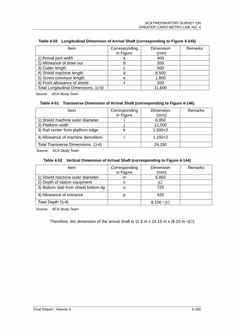
Final Report - Volume 3 4-190
Table 4-50 Longitudinal Dimension of Arrival Shaft (corresponding to Figure 4-145)
Item Corresponding in Figure
Dimension (mm)
Remarks
1) Arrival port width a 400 2) Allowance of draw out b 200 3) Cutter length c 500 4) Shield machine length d 8,500 5) Screw conveyor length e 1,800 6) Front allowance of shield f 200 Total Longitudinal Dimensions, 1)-6) 11,600
Table 4-51 Transverse Dimension of Arrival Shaft (corresponding to Figure 4-146)
Item Corresponding in Figure
Dimension (mm)
Remarks
1) Shield machine outer diameter i 6,950 2) Platform width j 12,000 3) Rail center from platform edge k 1,500×2
4) Allowance of machine demolition l 1,100×2
Total Transverse Dimensions, 1)-4) 24,150
Table 4-52 Vertical Dimension of Arrival Shaft (corresponding to Figure 4-144)
Item Corresponding in Figure
Dimension (mm)
Remarks
1) Shield machine outer diameter m 6,950 2) Depth of station equipment n 3) Bottom slab from shield bottom tip o 725
4) Allowance of entrance p 425
Total Depth 1)-4) 8,100+
Therefore, the dimension of the arrival shaft is 11.6 m x 24.15 m x (8.10 m +).
Source: JICA Study Team
Source: JICA Study Team
Source: JICA Study Team

JICA PREPARATORY SURVEY ON GREATER CAIRO METRO LINE NO. 4
Final Report - Volume 3 4-191
d) Required Space of Final Arrival Shaft (Horizontally-Located Tunnels)
The final arrival shaft is located in the station and the required space is the same
as that of other arrival shaft (horizontal).
e) Required Space of Arrival Shaft (Vertically-Located Tunnels)
Stations No.3 (El Nile) and No.4 (El Giza) are located in a congested area of
central Cairo and the width of the road above station is very narrow. It is difficult
to widen the station under this condition without extensive land acquisition. To
minimize the width of the station, two platforms are vertically separated (located at
different levels). Therefore, these stations need an arrival shaft where two
tunnels arrive and locate vertically. An example of the arrival shaft with vertically
located tunnels is shown in Figure 4-147.
Figure 4-147 Photo of Arrival Shaft (Vertical)
The dimension of the arrival shaft is determined by the required space for the
retrieval of the shield TBM in the longitudinal direction.
The longitudinal dimension of the arrival shaft is determined by the required space
for retrieval of shield TBM. The arrival shaft is transversely widened and tapered
from the normal part of the station (see Figure 4-150). It is necessary to shift to
the centre when the shield TBM passes in the shaft (station). The allowance, l,
(see Figure 4-150) for the shift of the shield TBM determines the transverse
dimension, taking the design width of the platform into consideration. The
platform width is 12 m in Station No.3 (El Nile) and 13m in Station No.4 (El Giza).
Source: Keio Corporation.

JICA PREPARATORY SURVEY ON GREATER CAIRO METRO LINE NO. 4
Final Report - Volume 3 4-192
The vertical dimension is determined by the requirement of the station design and
overburden.
Source: JICA Study Team
Figure 4-148 Plan of Launch and Arrival Shaft (Vertically Located Tunnels)
Source: JICA Study Team
Figure 4-149 Profile of Arrival Shaft (Vertically-Located Tunnels)
Source: JICA Study Team
Figure 4-150 Plan of Arrival Shaft (Vertically-Located Tunnels)

JICA PREPARATORY SURVEY ON GREATER CAIRO METRO LINE NO. 4
Final Report - Volume 3 4-193
Table 4-53 Longitudinal Dimension of Arrival Shaft (Vertical, Corresponding to Figure 4-149)
Item Corresponding
in Figure Dimension
(mm) Remarks
1) Arrival port width a 400 2) Allowance of draw out b 200 3) Cutter length c 500 4) Shield machine length d 8,500 5) Screw conveyor length e 1,800 6) Front allowance of shield f 200 Total longitudinal dimensions 1)-6) 11,600
Table 4-54 Transverse Dimension of Arrival Shaft (vertical, corresponding to Figure 4-150)
Item Corresponding in Figure
Dimension (mm)
Remarks
1) Shield machine outer diameter i 3,500 6950×1/2 2) Platform width j 12,000 (No.3 Sta.)
13,000 (No.4 Sta.) Side Platform
3) Rail centre from platform edge k 1,500
4) Allowance of machine assembly l 700
Total Transverse Dimensions, 1)-4) 17,700 (No.3 Sta.) 18,700 (No.4 Sta.)
Table 4-55 Vertical Dimension of Arrival Shaft (vertical, corresponding to Figure 4-152)
Item Corresponding in Figure
Dimension (mm)
Remarks
1) Shield machine outer diameter m 6,950×2
2) Depth of station equipment n
3) Bottom slab o 1,000
4) Allowance of entrance p1 525
5) Allowance of entrance p2 825
6) Bottom slab from shield bottom tip q 725×2
Total Vertical Dimension 1)-5) 17,700+
Therefore, the dimension of the arrival shaft is 11.6 m x 17.7 m x (17.7 m +) for
the Station No.3 (El Nile) and 11.6 m x 18.7 m x (17.7 m +) for the Station No.4
(El Giza).
Source: JICA Study Team
Source: JICA Study Team
Source: JICA Study Team

JICA PREPARATORY SURVEY ON GREATER CAIRO METRO LINE NO. 4
Final Report - Volume 3 4-194
f) Required Space of Launch Shaft (Vertically Located Tunnels)
After the shield TBM arrives at the shaft, it is moved in the station and re-launched.
The dimension of the launch shaft for vertical location of tunnels is determined the
same as the case for horizontal location of tunnels.
Figure 4-151 Profile of Launch Shaft (Vertically Located Tunnels)
Figure 4-152 Cross Section of Launch Shaft (Vertically Located Tunnels)
mq
hgfdcba
Source: JICA Study Team

JICA PREPARATORY SURVEY ON GREATER CAIRO METRO LINE NO. 4
Final Report - Volume 3 4-195
Table 4-56 Longitudinal Dimension of Launch Shaft (vertical, corresponding with Figure 4-151)
Item Corresponding in Figure
Dimension (mm)
Remarks
1) Entrance width a 600 2) Allowance width for excavating b 200 3) Cutter length c 500 4) Shield machine length d 8,500 5) Screw conveyor length e (1,800) 6) Temporary segment
f 2,000 Segment
Length 1.5m 7) Supporting g 2,200 8) Shield thrust supporting h (7,000) In the station Total Longitudinal Dimension 1)-7) 14,000
Table 4-57 Transverse Dimension of Launch Shaft (vertical, corresponding with Figure 4-152)
Item Corresponding in Figure
Dimension (mm)
Remarks
1) Shield machine outer diameter i 3,500 6950×1/2 2) Platform width j 12,000 (Sta.No.3)
13,000 (Sta.No.4) Side Platform
3) Rail center from platform edge k 1,500
4) Allowance of machine assembly l 700
Total Transverse Dimension 1)-4) 17,700 (Sta.No.3) 18,700 (Sta.No.4)
Source: JICA Study Team
Source: JICA Study Team

JICA PREPARATORY SURVEY ON GREATER CAIRO METRO LINE NO. 4
Final Report - Volume 3 4-196
(4) Study of Construction Yard of Launch Shaft
The shield TBM launches from Station No.14 and Station No. 9. The construction
yard of launch is used for the supply of the construction material and power and is
also used for the storage of the segmental lining. The allocation and layout of the
construction yard is studied.
a) Station No.9
There is an open space of approximately 10,000 m2 in close proximity of Station
No. 9. This space can be utilized for construction site office, mess, parking and
materials storage. Therefore, it is suitable to locate the launch shaft for section 1
of the Metro Line 4. The pyramid road is 40-45 m wide and the island type
construction yard is planned on the median and some part the road. The
construction yard is 12 m wide and approximately 2600 m2. Dual three lane
carriageway with side walk is secured during construction to prevent blockage of
existing traffic on pyramid road. The major equipments include portal crane,
plants for the backfill material and additive injection, pits for mucking, wastewater
plant, and power substation. In addition, the space for storage of lining and rail
segments has to be ensured. The outline of the construction yard is indicated in
Figure 4-153.
Source: JICA Study Team
Figure 4-153 Layout of the Launch Shaft Construction Yard of Station No. 9

JICA PREPARATORY SURVEY ON GREATER CAIRO METRO LINE NO. 4
Final Report - Volume 3 4-197
b) Station No.14
The construction yard of launch shaft is planned to be located on the open space
along the existing road. The storage space is prepared simultaneously with
Station No.9. The outline of the construction yard is indicated in Figure 4-154.
Source: JICA Study Team
Figure 4-154 Layout of the Launch Shaft Construction Yard of Station No.14

JICA PREPARATORY SURVEY ON GREATER CAIRO METRO LINE NO. 4
Final Report - Volume 3 4-198
4.7 Civil Works (Station)
4.7.1 Basic Condition
(1) Geological Condition
Geological survey was carried out at stations and intermediate points between stations.
Typical geological dada and corresponding analysis are presented and summarised in
section 4.6.1, Basic Condition of Civil Works (Tunnel).
(2) Basic Design Condition and Requirement
The basic design condition and requirement for the alignment, station, arrangement of
station facilities, etc are considered for the planning of the station. A summary of these
requirements is shown in Table 4-58.
Table 4-58 Basic Requirement for the Structural Planning
item contents
Railway alignment See Section 4.1
Station location See Section 4.1, 4.9
Arrangement of Station facilities See Section 4.9
Platform width of island type 12.0 m
Platform length 170.0 m
Minimum width of passenger corridor between platform screen door (PSD) and stairway and escalator
2.5 m
Tunnel type between stations single track double tunnel
Source: JICA Study Team
Taking into consideration the congested condition of central Greater Cairo City,
neighbouring structures, convenience and economical advantages, the main features of the
Metro Line 4 are studied and determined. The difference in major features between the
Metro Line 4 and other lines are as follows.
All stations of the Metro Line 4 (Phase 1) are underground.
Tunnel structure type of the Metro Line 4 is single track double tunnels. On
the other hand, that of the existing lines is double track single tunnel.
The platform of Metro Line 4 is mainly island type except for the two-storey
platform stations, namely, El Nile station and El Giza station. On the other
hand, those of the existing lines are side platform.
PSD is installed at all stations of Metro Line 4.

JICA PREPARATORY SURVEY ON GREATER CAIRO METRO LINE NO. 4
Final Report - Volume 3 4-199
Table 4-59 Comparison of Typical Features of Standard Stations
Metro Line 3 Metro Line 4
Name of standard station Abdou Pasha Station
M4W Station No.6
Number of story 3 3
Platform type side island Platform widths 7.015 m 12.0 m with PSD Platform length 150 m 170 m
Station inner width 20.0 m 21.0 m
Station length 150 m 190 m
Structure type 1 span rigid frame 3 spans rigid frame Retaining wall Diaphragm wall Diaphragm wall Minimum stairway width at platform
1.2 m 1.5 m
Tunnel type between stations
Double track single tunnel
Single track double tunnel
Remarks Under construction
Under planning
Source: JICA Study Team
(3) Outline Feature of Stations
The outline of the stations and major features are shown in Table 4-60 and Figure 4-155.

JICA PREPARATORY SURVEY ON GREATER CAIRO METRO LINE NO. 4
Final Report - Volume 3 4-200
Source: JICA Study Team
Figure 4-155 Outline of Stations of Metro Line 4 (Phase 1)

JICA PREPARATORY SURVEY ON GREATER CAIRO METRO LINE NO. 4
Final Report - Volume 3 4-201
Table 4-60 Outline of Station of Metro Line 4 (1/7)
M4W Station No.1 M4W Station No.2
El Malek El Saleh El Rauda
Outline of plane
a b c
Platform
Type Island and side 2 side
Width 8.0 m + 10.5 m 12.0 m
Pla
tform
length 170 m 170 m
Structural type 2 span rigid frame with 4 storeys 2 span rigid frame with 4 storeys
Inner width 26.0 m 24.0 m
Outer width 29.0 m 27.0 m Sca
le
Bottom depth 32.1 m 35.6 m
Addition (a) 10 m 10 m
Platform (b) 170 m 170 m
Addition (c) 10 m 10 m Leng
th
Total (a+b+c) 190 m 190 m
B1 level Entrance square, Concourse,
Station office
Entrance square, Concourse, Station office,
Environmental control System, Electric room
B2 level
Passenger corridor, Air handling unit,
Environmental control System, Electric room
Passenger corridor, Air handling unit
B3 level
Stair, escalator and elevator, Air handling unit,
Tunnel ventilation fans, Tunnel exhaust fans
Stair, escalator and elevator, Tunnel ventilation fans, Tunnel exhaust fans,
Spare space for facility room
Fac
ility
arr
ange
men
t
B4 level Platform,
Drainage equipment (both ends)Platform,
Drainage equipment (both ends)Source: JICA Study Team

JICA PREPARATORY SURVEY ON GREATER CAIRO METRO LINE NO. 4
Final Report - Volume 3 4-202
Table 4-61 Outline of Station of Metro Line 4 (2/7)
M4W Station No.3 M4W Station No.4
El Nile El Giza
Outline of plane
Type 2 side (2 storeys) 2 side (2 storeys)
Width 12.0 m 13.0 m
Pla
tform
length 170 m 170 m
Structural type 1 span rigid frame with 5 storeys 1 span rigid frame with 5 storeys
Inner width 16.5 m 18.5 m
Outer width 19.5 m 21.5 m Sca
le
Bottom depth 44.6 m 36.6 m
Addition (a) 25 m 25 m
Platform (b) 170 m 170 m
Addition (c) 40 m 25 m Leng
th
Total (a+b+c) 235 m 220 m
B1 level
Entrance square, Concourse, Station office,
Environmental control System, Electric room
Entrance square, Concourse, Station office,
Air handling unit
B2 level Passenger corridor,
Electric room, Sub station
Passenger corridor, Environmental control System
Electric room Spare space for E/M room
B3 level
Passenger corridor, Air handling unit,
Electrical supply station, Tunnel ventilation fans,
Tunnel exhaust fans
Passenger corridor, Air handling unit,
Tunnel ventilation fans, Tunnel exhaust fans,
Spare space for E/M room
B4 level Platform,
Tunnel ventilation fans Platform,
Tunnel ventilation fans
Fac
ility
arr
ange
men
t
B5 level Platform,
Drainage equipment Platform,
Drainage equipment Source: JICA Study Team

JICA PREPARATORY SURVEY ON GREATER CAIRO METRO LINE NO. 4
Final Report - Volume 3 4-203
Table 4-62 Outline of Station of Metro Line 4 (3/7)
M4W Station No.5 M4W Station No.6
El Mesaha Square Madkour
Outline of plane
a b c
Platform
a b c
Platform
Type Island Island
Width 12.0 m 12.0 m
Pla
tform
length 170 m 170 m
Structural type 3 span rigid frame with 2 storeys 3 span rigid frame with 3 storeys
Inner width 21.0 m 21.0 m
Outer width 23.4 m 23.4 m Sca
le
Bottom depth 20.1 m 27.1 m
Addition (a) 115 m for ENR access line 10 m
Platform (b) 170 m 170 m
Addition (c) 290 m for head shunting line 10 m Leng
th
Total (a+b+c) 575 m 190 m
B1 level
Entrance square, Concourse, Station office,
Environmental control System, Electric room,
Air handling unit, Tunnel ventilation fans, Tunnel exhaust fans,
Sub station
Entrance square, Concourse,
Station office, Environmental control System,
Electric room
B2 level
Platform, Drainage equipment,
Air handling unit, ENR access line, head shunting line
Passenger corridor, Air handling unit,
Tunnel ventilation fans, Tunnel exhaust fans
Fac
ility
arr
ange
men
t
B3 level - Platform,
Drainage equipment Source: JICA Study Team

JICA PREPARATORY SURVEY ON GREATER CAIRO METRO LINE NO. 4
Final Report - Volume 3 4-204
Table 4-63 Outline of Station of Metro Line 4 (4/7)
M4W Station No.7, 8 M4W Station No.9
El Talbeya and El Matabaa Hassan Mohammed
Outline of plane
a b c
Platform
Type island Island
Width 12.0 m 12.0 m
Pla
tform
length 170 m 170 m
Structural type 3 span rigid frame with 3 storeys 3 span rigid frame with 2 storeys
Inner width 21.0 m 21.0 m
Outer width 23.4 m 23.4 m Sca
le
Bottom depth 27.1 m 20.1 m
Addition (a) 10 m 10 m
Platform (b) 170 m 170 m
Addition (c) 10 m 290 m for head shunting line Leng
th
Total (a+b+c) 190 m 470 m
B1 level
Entrance square, Concourse,
Station office, Environmental control System,
Electric room
Entrance square, Concourse, Station office,
Environmental control System, Electric room,
Air handling unit, Tunnel ventilation fans, Tunnel exhaust fans,
Sub station
B2 level
Passenger corridor, Air handling unit,
Tunnel ventilation fans, Tunnel exhaust fans
Platform, Drainage equipment,
Air handling unit, head shunting line
Fac
ility
arr
ange
men
t
B3 level Platform,
Drainage equipment -
Source: JICA Study Team

JICA PREPARATORY SURVEY ON GREATER CAIRO METRO LINE NO. 4
Final Report - Volume 3 4-205
Table 4-64 Outline of Station of Metro Line 4 (5/7)
M4W Station No.10, 11 M4W Station No.12
Maryoutia and Al Ahramat El Remayah
Outline of plane
a b c
Platform
Type island Island
Width 12.0 m 14.0 m
Pla
tform
length 170 m 170 m
Structural type 3 span rigid frame with 3 storeys 1 span rigid frame with 2 storeys
Inner width 21.0 m 23.0 m
Outer width 23.4 m 26.0 m Sca
le
Bottom depth 29.6 m 22.6 m
Addition (a) 10 m 35 m
Platform (b) 170 m 170 m
Addition (c) 10 m 40 m Leng
th
Total (a+b+c) 190 m 245 m
B1 level
Entrance square, Concourse,
Passenger corridor, Station office,
Environmental control System, Electric room,, Air handling unit
Entrance square, Concourse, Station office,
Air handling unit, Environmental control System,
Electric room,
B2 level
Passenger corridor, Air handling unit,
Tunnel ventilation fans, Tunnel exhaust fans
Platform, Drainage equipment,
Air handling unit, Tunnel ventilation fans,
Tnnel exhaust fans, Electric room,
Sub station
Fac
ility
arr
ange
men
t
B3 level Platform,
Drainage equipment -
Source: JICA Study Team

JICA PREPARATORY SURVEY ON GREATER CAIRO METRO LINE NO. 4
Final Report - Volume 3 4-206
Table 4-65 Outline of Station of Metro Line 4 (6/7)
M4W Station No.13 M4W Station No.14
GEM -
Outline of plane
a b c
Platform
a b c
Platform
Type 2 side (2 storeys) Island
Width 12.0 m 12.0 m
Pla
tform
length 170 m 170 m
Structural type 1 span rigid frame with 5 storeys 3 span rigid frame with 3 storeys
Inner width 16.5 m 21.0 m
Outer width 19.5 m 23.4 m Sca
le
Bottom depth 40.1 m 25.6 m
Addition (a) 10 m 25 m
Platform (b) 170 m 170 m
Addition (c) 10 m 35 m Leng
th
Total (a+b+c) 190 m 230 m
B1 level
Entrance square, Concourse, Station office,
Environmental control System, Electric room
Entrance square, Concourse, Station office, Electric room,
Sub station
B2 level
Passenger corridor, Electric room,
Sub station
Passenger corridor, Environmental control System,
Air handling unit, Tunnel ventilation fans,
Tunnel exhaust fans
B3 level
Passenger corridor, Air handling unit,
Tunnel ventilation fans, Tunnel exhaust fans
Platform, Tunnel ventilation fans,
Air handling unit, Drainage equipment
B4 level Platform,
Tunnel ventilation fans -
Fac
ility
arr
ange
men
t
B5 level Platform,
Drainage equipment -
Source: JICA Study Team

JICA PREPARATORY SURVEY ON GREATER CAIRO METRO LINE NO. 4
Final Report - Volume 3 4-207
Table 4-66 Outline of Station of Metro Line 4 (7/7)
M4W Station No.15
-
Outline of plane
a b c
Platform
Type 2 Islands
Width 12.0 m + 12.0 m
Pla
tform
length 170 m
Structural type 3 span rigid frame with 2 storeys
Inner width 40.0 m
Outer width 42.4 m Sca
le
Bottom depth 20.6 m
Addition (a) 10 m
Platform (b) 170 m
Addition (c) 40 m Leng
th
Total (a+b+c) 220 m
B1 level
Entrance square, Concourse, Station office,
Environmental control System, Electric room,
Air handling unit, Tunnel ventilation fans, Tunnel exhaust fans,
Sub station
Fac
ility
arr
ange
men
t
B2 level Platform,
Drainage equipment, Air handling unit
Source: JICA Study Team

JICA PREPARATORY SURVEY ON GREATER CAIRO METRO LINE NO. 4
Final Report - Volume 3 4-208
4.7.2 Required Clearance and Space
(1) Structural Gauge and Inner Cross Section of Station
The inner cross section of the platform level is shown in Figure 4-156. The major feature
of the clearance is as follows:
Clearance between the rolling stock gauge and the column of PSD is 200 mm.
Therefore, distance between track centre and edge of platform is 1500 mm.
Distance between the edge of the track and wall is planned to be 1360 mm
taking into consideration the clearance for the maintenance work.
Source: JICA Study Team
Figure 4-156 Structural Gauge and Inner Cross Section of Station
The station is composed of the spaces for the platform, concourse, entrance square,
electrical and mechanical rooms and station office. In order to provide appropriate space
for each facility and rooms, the required heights are planned as follows.
Table 4-67 Planned Height of Facilities and Rooms in Station
Finishing of floor H0 (mm)
Required Height (mm)
Duct space on ceiling (mm)
Standard height H (mm)
Minimum height H mm)
Platform 100 2700-3400 5000 4300
Concourse
Station office
200 2700-3300 1500
5000 4400
E&M room - 4000-5000 - 5000 4000
Sub-station - 6000 - 6000 6000
Source: JICA Study Team

JICA PREPARATORY SURVEY ON GREATER CAIRO METRO LINE NO. 4
Final Report - Volume 3 4-209
Source: JICA Study Team
Figure 4-157 Height of Spaces and Rooms in Station
(2) Distribution of Structural Column at Platform
PSD is planned to be installed in Metro Line 4. Taking into account the array of the PSD,
spacing between columns is proposed to be 10.0 m as shown in Figure 4-158.
10000 10000
Car length 20000 15
00
car
platform column PSD
Structural column span
600
Source: JICA Study Team
Figure 4-158 Distribution of Structural Columns and Array of the PSD
(3) Width of Escalator and Stairway at Platform
Minimum width of escalator and stairway is shown in Figure 4-159. The provision for
escalator and stairway includes the space for the interior finish on wall and column.
Effective width of stairway should be more than 1500 mm.

JICA PREPARATORY SURVEY ON GREATER CAIRO METRO LINE NO. 4
Final Report - Volume 3 4-210
Escalator
1900 1900
1800 1500 20050 50 200
Stairway
Source: JICA Study Team
Figure 4-159 Minimum Width of Escalator and Stairway
4.7.3 Study of Structure for Standard Station
The structure of the standard station is studied taking into account size of the station,
construction cost and service level for the passengers. The possible structural types for
the standard station are the three-storey type, two-storey type and the two-storey type with
atrium. Since each structural type has advantage and disadvantage, a comparative study is
carried out.
(1) Cross-Sectional Structure of the Standard Station
The platform structure for the standard station is studied. The passenger corridors at
platform are important space for the safety and smooth operation of station. The minimum
width of the passenger corridors is 2500 mm. In order to assure this space on the platform,
the location of structural columns, escalators, stairway, PSD are arranged as illustrated in
Figure 4-160. The structural columns are used to support both the station structure and
the PSD. The structural section of each station type is shown in Figure 4-161 to Figure
4-163.

JICA PREPARATORY SURVEY ON GREATER CAIRO METRO LINE NO. 4
Final Report - Volume 3 4-211
Columnt=800
Columnt=800
PlatformScreenDoor
PlatformScreenDoor
30001500Platform width 120003000 1500
1050 3050
5100 10800
10503050
5100
38003500 3500
Passengercorridor
Passengercorridor
Escalator& Stairway≧2500 ≧2500
Source: JICA Study Team
Figure 4-160 Platform Structure Plan of a Standard Station
Source: JICA Study Team
Figure 4-161 Section of Standard Three-storey Station

JICA PREPARATORY SURVEY ON GREATER CAIRO METRO LINE NO. 4
Final Report - Volume 3 4-212
Source: JICA Study Team
Figure 4-162 Section of Standard Two-storey Station
Source: JICA Study Team
Figure 4-163 Section of Standard Two-storey Station with Atrium
(2) Plan of the Standard Station
The station length is determined by the required space and arrangement of platform,
stairway, electrical and mechanical rooms, station office and entrance square. Plan for
each type of station is illustrated as follows.

JICA PREPARATORY SURVEY ON GREATER CAIRO METRO LINE NO. 4
Final Report - Volume 3 4-213
Paid concourseEntrance square
Entrance
Station facilities
Entrance
B2 level
Platform length 170 m
Station facilities
Station facilities Station facilities
Entrance square
Station length 190 mShieldtunnel
Shieldtunnel
Stair&Escalator
B1 level
B3 level
Station facilities
Source: JICA Study Team
Figure 4-164 Plan of Standard Three-storey Station
Source: JICA Study Team
Figure 4-165 Plan of Standard Two-storey Station
Source: JICA Study Team
Figure 4-166 Plan of Standard Two-storey Station with Atrium
Atriu

JICA PREPARATORY SURVEY ON GREATER CAIRO METRO LINE NO. 4
Final Report - Volume 3 4-214
(3) Comparison of the Three Types of Structure as Standard Station
Comparison among the three types of structure is carried out taking into account the
service level for the passengers and construction cost. The service level and construction
cost are compared in terms of trade off. In order to determine the structure of the standard
station, the construction cost is mainly focused for comparison. The comparison is
summarised in Table 4-68.
Table 4-68 Comparison of Structures for the Standard Station
Two-storey type Three-storey type
Without atrium With atrium
Outline (cross section)
Inner width of Station
21.0 m 21.0 m 21.0 m
Station length 190.0 m 280.0 m 320.0 m
Accessibility from concourse to platform
Vertical distance: 13 m use of stairway: 2 times
Vertical distance: 6.0 muse of stairway: 1 time
Vertical distance: 6.0 muse of stairway:1time
Volume of Excavation
About 104,500 m3 About 113,000 m3 About 129,000 m3
Concourse (B1 level)
Area: 2,730 ㎡ Entrance square: 2 places
Area: 2,310 ㎡ Entrance square: 1 place
Area: 3,570 ㎡ Entrance square: 2 places
Construction costs ratio
1.0 1.08 1.23
Construction Period ratio
1.0 1.2 1.4
Characteristic
Most economical for construction cost, and similar to Metro Line 3 under construction
Most convenient for passengers, but expensive for construction
Most Convenient and comfortable for passengers,but most expensive for Construction
Recommendation For typical standard Station of Metro Line 4
For long length station required by another reason like turn-back track
For only special station of Metro Line 4
Applicable station No.6, 7,8,10,11,14 No.5, 9 inapplicable
Source: JICA Study Team
Atrium

JICA PREPARATORY SURVEY ON GREATER CAIRO METRO LINE NO. 4
Final Report - Volume 3 4-215
(4) Consideration of the Shield TBM Passing for the Standard Station
According to the overall construction schedule, it is necessary for the shield TBM to pass
through some stations. In that case, the height of the platform level should be increased
to allow for the passage of the shield TBM. The vertically elongated stations are illustrated
in Figure 4-167 and Figure 4-168.
Source: JICA Study Team
Figure 4-167 Elongated Standard Three-storey Station
Source: JICA Study Team
Figure 4-168 Elongated Standard Two-storey Station

JICA PREPARATORY SURVEY ON GREATER CAIRO METRO LINE NO. 4
Final Report - Volume 3 4-216
(5) Consideration of the Location for Structural Column on the Platform
With regard to the installation of structural columns at platform edge, further study will be
required and carried out considering the following aspects.
a) Installation of the PSD
The PSDs should be installed at appropriate positions.
b) Operation
Columns on the platform should not hamper any operation of train service and
safety of the passengers.
c) Visibility
The clear visibility of the driver/station staffs on the platform should be ensured
without any invisible spaces.
In case the columns at the edge of the platform hamper the operation of train
services and installation of the PSD at appropriate position, consequently affecting
the visibility of the driver/station staffs on the platform, relocation of said columns
further inside the platform will be considered and studied. Cross sections of the
standard stations are shown in Figure 4-169
Three storeys Two storeys
Figure 4-169 Relocation of Columns for Standard Stations

JICA PREPARATORY SURVEY ON GREATER CAIRO METRO LINE NO. 4
Final Report - Volume 3 4-217
4.7.4 Study of Structure for Other Stations
Some stations are located in densely populated and congested areas where there are
constrains on land use at the ground level. In order to avoid some structures or minimize
land acquisition, the alignment and station structures are significantly affected. Besides,
the alignment is vertically deepened at the Nile River crossing and the depth of the station
in its vicinity is also considerably affected. The station structures in said area are different
from that of the standard stations which are located under Pyramid Street. The structures
of such stations are studied in this section.
(1) M4W Station No.1(El Malek El Saleh Station)
a) Control Points and Important Factors
The El Malek El Saleh Station is located in the proximity of hospital, mosque and
existing El Malek El Saleh Station of Metro Line 1. Furthermore, the turn back
track is installed behind said station. Therefore, the control points and important
factors for the station planning are summarised as follows.
Avoid Misrel Gadima Hospital as much as possible
Minimize land acquisition
Facilitate the passenger’s transfer between Metro Line 1 and 4
Minimize the damage and influence to El Malek El Saleh Tunnel
Shorten the turn back track section as much as possible
Source: JICA Study Team
Figure 4-170 Plan of El Malek El Saleh Station

JICA PREPARATORY SURVEY ON GREATER CAIRO METRO LINE NO. 4
Final Report - Volume 3 4-218
b) Structure of Station
The structure of the El Malek El Saleh Station is studied taking into account control
points and important factors. The characteristics of the structure of station are as
follows.
Station is composed of four storeys and two-span rigid frame structure.
The structural column is used to support both the station structure and PSD to
ensure appropriate space for the passenger corridor.
Two platforms (side and island) are irregularly positioned to maintain the
capacity of platform and shorten the turn back section as much as possible.
The excavation depth is 32 m.
Source: JICA Study Team
Figure 4-171 Structure of El Malek El Saleh Station
c) Consideration for the Opening of Intermediate Slab
In order to install the stairway and escalator, a large opening is provided on the
intermediate slab. In that case, the structural study for the influence of the
opening is necessary. The opening gives impact on the vertical support
mechanism of the slab and lateral support mechanism of the diaphragm wall.
The large opening and other required spaces is illustrated in Figure 4-172.

JICA PREPARATORY SURVEY ON GREATER CAIRO METRO LINE NO. 4
Final Report - Volume 3 4-219
Source: JICA Study Team
Figure 4-172 Large Opening for the Stairway and Escalator
The vertical support mechanism of the slab and lateral support mechanism of the
diaphragm wall are illustrated in Figure 4-173.
In case that large opening is provided on the intermediate slab, the
diaphragm wall will be supported by the top slab and the slab of B2 floor
against the lateral load.
In order to reinforce the vertical support which weakened by the opening on
the slab, supplemental structural walls and columns are installed as indicated
in Figure 4-173.
Source: JICA Study Team
Figure 4-173 Arrangement of the Supplemental Structural Wall and Column to Support Large Opening on Slabs
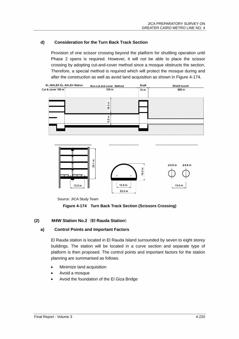
JICA PREPARATORY SURVEY ON GREATER CAIRO METRO LINE NO. 4
Final Report - Volume 3 4-220
d) Consideration for the Turn Back Track Section
Provision of one scissor crossing beyond the platform for shuttling operation until
Phase 2 opens is required. However, it will not be able to place the scissor
crossing by adopting cut-and-cover method since a mosque obstructs the section.
Therefore, a special method is required which will protect the mosque during and
after the construction as well as avoid land acquisition as shown in Figure 4-174.
Source: JICA Study Team
Figure 4-174 Turn Back Track Section (Scissors Crossing)
(2) M4W Station No.2(El Rauda Station)
a) Control Points and Important Factors
El Rauda station is located in El Rauda Island surrounded by seven to eight storey
buildings. The station will be located in a curve section and separate type of
platform is then proposed. The control points and important factors for the station
planning are summarised as follows.
Minimize land acquisition
Avoid a mosque
Avoid the foundation of the El Giza Bridge

JICA PREPARATORY SURVEY ON GREATER CAIRO METRO LINE NO. 4
Final Report - Volume 3 4-221
Source: JICA Study Team
Figure 4-175 Plan of El Rauda Station
b) Structure of Station
The structure of the El Rauda Station is studied taking into account the control
points and important factors. The characteristics of the structure of the station
are as follows:
Station is composed of four storeys and two-span rigid frame structure.
The structural column is used to support both the station structure and the
PSD to ensure appropriate space for the passenger corridor.
Two platforms (side and island) are irregularly installed to maintain the
capacity of the platform.
The excavation depth is about 36.6 m.

JICA PREPARATORY SURVEY ON GREATER CAIRO METRO LINE NO. 4
Final Report - Volume 3 4-222
100
060
00
670
01
000
366
00
2000
3000 8000 8000
24000
1500 1500
11500
1000
150
064
00
500
06
000
1190012100
3500
150
0
150
0
2000
350
0500
011
00
600
Source: JICA Study Team
Figure 4-176 Structure of El Rauda Station
c) Consideration for the Opening of Intermediate Slab
In order to install the stairway and escalator, a large opening is provided on the
intermediate slab. In that case, the structural study for the influence of the
opening is necessary. The opening gives impact on the vertical support
mechanism of the slab and lateral support mechanism of the diaphragm wall.
The large opening and other required spaces is illustrated in Figure 4-177.
Platform 8000
3100
400
1500
Intermediate slab
Passengercorridor
Platform 8000
2500 1900
1500 2000
PlatformScreenDoor
400 1900450
3500
3000
250
Intermediate slab
850
Escalator
Structural column(t=800)
Structural column(t=800)
Stairway
Passengercorridor
19001900
EscalatorStairway
PlatformScreenDoor
Structural wall (t=400)
4500
Structural wall (t=400)
12100 11900
450
Source: JICA Study Team
Figure 4-177 Large Opening for the Stairway and Escalator

JICA PREPARATORY SURVEY ON GREATER CAIRO METRO LINE NO. 4
Final Report - Volume 3 4-223
(3) M4W Station No.3(El Nile Station)
a) Control Points and Important Factors
El Nile station is located under the Giza Flyover. A new pedestrian underpass
which crosses this flyover is under construction to connect with an existing bus
terminal and other sidewalk. Control points and important factors for the station
planning are summarised as follows:
Minimize land acquisition
Facilitate a safe and efficient station access route for passengers
Minimize the damage and demolishment of Giza Flyover
To EL MALEK EL SALEH
To EL REMAYAH
Station length 235 m
Platform length 170 mGIZA Square
EL GIZA Flyover Ramp
Source: JICA Study Team
Figure 4-178 Plan of El Nile Station
b) Structure of Station
The structure of El Nile Station is studied taking into account control points and
important factors. The station is deepest among Metro Line 4 stations. The
characteristics of the structure of station are as follows.
It is composed of five storeys and one span rigid frame structure.
Two storeys platform is provided to minimize land acquisition.
Roof slab of station must be able to support the foundation of flyover bridges
Excavation depth is about 43.6 m.

JICA PREPARATORY SURVEY ON GREATER CAIRO METRO LINE NO. 4
Final Report - Volume 3 4-224
600
010
0039
700
2000
1100
530
0
12000
16500
1500
150
038
00
600
1000
100
01
500
4900
500
060
00
3000
820
010
00
3250
095
00
7000
150
035
00
1100
210
0
350
0
4200
0
150
0
446
00
600
01
000
325
00
200
010
00
100
015
0049
00
500
060
0082
0010
0039
700
9500
4200
0
700
0
680
068
0027
0021
00
130
0
900
600
600
6400
210
061
0025
00
10000
Source: JICA Study Team
Figure 4-179 Structure of El Nile Station
c) Consideration for the Opening of Intermediate Slab
In order to install the stairway and escalator, a large opening is arranged on the
intermediate slab. In such case, the structural study for the influence of the
opening is necessary. The opening gives impact on the vertical support
mechanism of the slab and lateral support mechanism of the diaphragm wall.
The large opening and other required spaces are illustrated in Figure 4-180.
1500
Platform 12000 1500 3000
75019001900
450
Stairway
Structural wall (t=400)
Intermediate slab
PlatformScreenDoor
Passengercorridor
Structural column(500)
Escalator
5500
corridor for Maintenance
1500 3800 6700 3000 1500
Structural beam
Opnenning of slab
Source: JICA Study Team
Figure 4-180 Large Opening for the Stairway and Escalator

JICA PREPARATORY SURVEY ON GREATER CAIRO METRO LINE NO. 4
Final Report - Volume 3 4-225
In this station, support mechanism of diaphragm wall poses a serious problem,
because the openings of the four slabs are at the same location of the stairway
arrangement. Structural beams should be constructed for the purpose of ensuring
the stability of the diaphragm wall.
Source: JICA Study Team
Figure 4-181 Support Mechanism in case of Open Slab
(4) M4W Station No.4(El Giza Station)
a) Control Points and Important Factors
El Giza station is located near the Al Ahram underpass and crosses under the
ENR line and a Metro Line 2 viaduct station. The control points and important
factors for the station planning are summarised as follows.

JICA PREPARATORY SURVEY ON GREATER CAIRO METRO LINE NO. 4
Final Report - Volume 3 4-226
Minimize land acquisition
Facilitate the passenger’s transfer between Metro Line 2 and 4
Minimize the damage and demolishment to Pyramids Road underpass
Reduce influence on traffic of Al Aharam underpass during the construction
It is inevitable to demolish some part of Al Aharam underpass (see Figure
4-183). In order to minimize the influence and restore Al Aharam underpass,
dividing the station construction may possibly be adopted. In this case, the
construction period will be longer and TBM will be driven before the station
excavation. Therefore, this possibility is also considered for the study of
station structure.
To EL REMAYAH
AL AHRAM Underpass
Station length 220 m
Platform length 170 m
Transfer corridor
Lin
e-2
GIZ
A
Sta
tio
n
Proposed Sation Praza
Entrance square
of Station
To EL MALEKEL SALEH
Source: JICA Study Team
Figure 4-182 Plan of El Giza Station
b) Structure of Station
The structure of El Giza Station is studied taking into account the control points
and important factors. The characteristics of the structure of station are as
follows.
Station is composed of five storeys and one span rigid frame.
Two-storey platform is installed to minimize land acquisition.
The excavation depth is about 36.6m.

JICA PREPARATORY SURVEY ON GREATER CAIRO METRO LINE NO. 4
Final Report - Volume 3 4-227
5000
900
500
0
110
050
00
13000
18500
15001500
3500
1000
100
010
00
500
070
00
100
0
260
008
000
3400
0
150
035
00
110
090
0
6700
200
010
00
600
4000
3660
0
Source: JICA Study Team
Figure 4-183 Cross Section of El Giza Station
c) Consideration for the Opening of Intermediate Slab
The large opening affects the vertical support mechanism of the slab and lateral
support mechanism of the diaphragm wall, same as El Nile station.
(5) M4W Station No.12(El Remayah Station)
a) Structure of Station
The structure of El Remayah Station is studied taking into account control points
and important factors. The characteristics of the structure of the station are as
follows:
Station is composed of one storey and one span rigid frame structure.
The excavation depth is about 22.6 m
AL AHRAM Underpass

JICA PREPARATORY SURVEY ON GREATER CAIRO METRO LINE NO. 4
Final Report - Volume 3 4-228
Source: JICA Study Team
Figure 4-184 Cross Section of El Remayah Station
The location of structural columns, escalators, stairway, and PSD are arranged as
illustrated in Figure 4-185.
Source: JICA Study Team
Figure 4-185 Section of Platform Structure of El Remayah Station

JICA PREPARATORY SURVEY ON GREATER CAIRO METRO LINE NO. 4
Final Report - Volume 3 4-229
(6) N4W Station No.13 (GEM)
a) Structure of Station
The structure of GEM Station is studied taking into account control points and
important factors. The characteristics of the structure of station are as follows.
Station is composed of one span rigid frame with five storeys.
Two-storey platform is installed to minimize land acquisition
The excavation depth is about 40.1 m
Structural type is same as El Nile Station.
Source: JICA Study Team
Figure 4-186 Cross Section of Station No. 13
(7) N4W Station No.15
a) Structure of Station
The structure of No.15 Station is studied taking into account control points and
important factors. The characteristics of the structure of station are as follows:
Station is composed of three-span rigid frame with two storeys.
Inner width of the station is the widest among the Metro Line 4 stations as the
terminal consist of two platforms.
The excavation depth is about 20.6 m

JICA PREPARATORY SURVEY ON GREATER CAIRO METRO LINE NO. 4
Final Report - Volume 3 4-230
Source: JICA Study Team
Figure 4-187 Cross Section of Station No. 15
6700
200
050
00
100
0
4400
2060
0
1500
1620
0
40000
3000 15000 4000 15000 3000
12000 12000
600
1100 50
00
820015900 15900
Related Documents