GARRETT WADE TECHNICAL MEMO T60 Supplementary English Instructions for the Assembly and Operation of the DIY Chain Saw Sharpener Quick Feed Model: GW Product 45T01.02 Your Sharpener comes packed with thorough safety, assembly and operating instructions in a number of languages. It’s important to read and understand them; however, we have found the English translation of the assembly and operation instructions sometimes to be awkward in phrasing and inaccurate on the electric specifics for the USA, so we have prepared this supplement to aid you and make your work more efficient. Read this carefully. If you have any questions, do not hesitate to contact a Garrett Wade technician for assistance. Always follow safe and sensible procedures. Always wear safety glasses (goggles) when running the motor and make sure the unit is securely attached to your work surface. Always set up and adjust the unit with the power cord unplugged. Always work in a clean area free of tools and objects, at a safe distance from any flammable substance or rags (grinding wheels cause some sparking during normal operation). Always practice caution (or wear gloves) when handling the chain. Never tamper with or in any way modify the unit. Never allow children to operate the unit. The unit is intended ONLY to be used to re-sharpen chain saw chains. Do not use it for any other purpose. Your machine is equipped with an 115V 60 Hz motor and can be plugged into any standard 115V 15A outlet. Once your sharpener is set up, you will find it can be used easily and efficiently time and time again. Before first using the Sharpener, inspect the grinding wheel for cracks or chips and replace if necessary (we stock replacement wheels). Never use a defective grinding wheel. (Tip: “Hang” the wheel by inserting a pencil through the arbor hole and lightly strike its edge with a non-metallic object, such as a screwdriver handle or another pencil. If the wheel is in good condition, this will produce a metallic sound; a dull sound indicates that the grinding wheel is cracked or otherwise defective, and should be replaced). As an extra precaution before any cutting action, first run the Sharpener for about 30 seconds to make sure there is no unexpected vibration. Replace the grinding wheel when it has worn to a diameter of 75mm (2.925”) BASICS OF THE SAW CHAIN Before you begin, it would be helpful to review some basics: A saw chain comprises five basic parts – left-hand cutter, right- hand cutter, tie-straps, drive links and rivets. The alternating left-right cutters are the primary focus during sharpening. Each cutter features a ramp-like depth-limiting gauge (or raker) at the front and a gouge- like cutting element (tooth) at the rear. The gulf between is the gullet. The cutting element has a profile that resembles the number “7”; its two surfaces, the top plate and the side plate, contain three different angles. The top-plate angle (Fig. 2: A) is the familiar 25-35 degree angle you see when you look down on the chain; the top-plate cutting angle (B) is the bevel on the underside of the top plate; the side-plate angle (C) is the beveled arc in the side plate. Getting the angles exactly right is not as important as removing all damage from the side and top plate and making sure the critical top corner is really sharp. Careful position and accurate adjustment of the chain in the chain guide of the sharpener is the key. Take your time - check repeatedly how the grinding wheel engages these cutter angles while setting up the first tooth. Once properly adjusted, the sharpener will accurately grind each tooth the same.

Welcome message from author
This document is posted to help you gain knowledge. Please leave a comment to let me know what you think about it! Share it to your friends and learn new things together.
Transcript
GARRETT WADE TECHNICAL MEMO T60
Supplementary English Instructions for the Assembly and Operation of the DIY Chain Saw Sharpener Quick Feed Model: GW Product 45T01.02
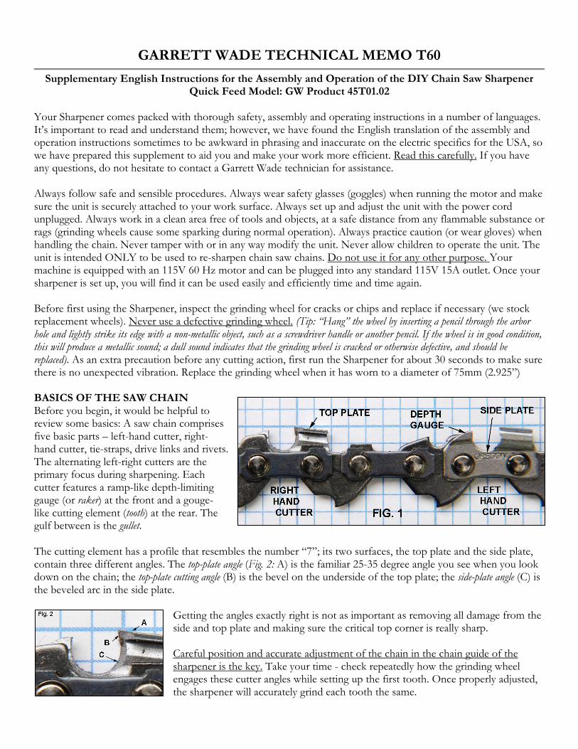
Your Sharpener comes packed with thorough safety, assembly and operating instructions in a number of languages. It’s important to read and understand them; however, we have found the English translation of the assembly and operation instructions sometimes to be awkward in phrasing and inaccurate on the electric specifics for the USA, so we have prepared this supplement to aid you and make your work more efficient. Read this carefully. If you have any questions, do not hesitate to contact a Garrett Wade technician for assistance. Always follow safe and sensible procedures. Always wear safety glasses (goggles) when running the motor and make sure the unit is securely attached to your work surface. Always set up and adjust the unit with the power cord unplugged. Always work in a clean area free of tools and objects, at a safe distance from any flammable substance or rags (grinding wheels cause some sparking during normal operation). Always practice caution (or wear gloves) when handling the chain. Never tamper with or in any way modify the unit. Never allow children to operate the unit. The unit is intended ONLY to be used to re-sharpen chain saw chains. Do not use it for any other purpose. Your machine is equipped with an 115V 60 Hz motor and can be plugged into any standard 115V 15A outlet. Once your sharpener is set up, you will find it can be used easily and efficiently time and time again. Before first using the Sharpener, inspect the grinding wheel for cracks or chips and replace if necessary (we stock replacement wheels). Never use a defective grinding wheel. (Tip: “Hang” the wheel by inserting a pencil through the arbor hole and lightly strike its edge with a non-metallic object, such as a screwdriver handle or another pencil. If the wheel is in good condition, this will produce a metallic sound; a dull sound indicates that the grinding wheel is cracked or otherwise defective, and should be replaced). As an extra precaution before any cutting action, first run the Sharpener for about 30 seconds to make sure there is no unexpected vibration. Replace the grinding wheel when it has worn to a diameter of 75mm (2.925”) BASICS OF THE SAW CHAIN Before you begin, it would be helpful to review some basics: A saw chain comprises five basic parts – left-hand cutter, right-hand cutter, tie-straps, drive links and rivets. The alternating left-right cutters are the primary focus during sharpening. Each cutter features a ramp-like depth-limiting gauge (or raker) at the front and a gouge-like cutting element (tooth) at the rear. The gulf between is the gullet.
The cutting element has a profile that resembles the number “7”; its two surfaces, the top plate and the side plate, contain three different angles. The top-plate angle (Fig. 2: A) is the familiar 25-35 degree angle you see when you look down on the chain; the top-plate cutting angle (B) is the bevel on the underside of the top plate; the side-plate angle (C) is the beveled arc in the side plate.
Getting the angles exactly right is not as important as removing all damage from the side and top plate and making sure the critical top corner is really sharp. Careful position and accurate adjustment of the chain in the chain guide of the sharpener is the key. Take your time - check repeatedly how the grinding wheel engages these cutter angles while setting up the first tooth. Once properly adjusted, the sharpener will accurately grind each tooth the same.

SET UP AND OPERATION
1. MOTOR
2. BASE
3. TURRET
4. WHEEL GUARD
5. GRINDING WHEEL
6. DEPTH STOP ADJUSTMENT
7. CHAIN STOP AJUSTMENT
8. SLIDE INTERVAL ADJUSTMENT
9. TURRET LOCK KNOB
10. M8 NUT
11. M8 NUT
12. M8x 100 HEX BOLT
13. CHAIN STOP
14. SPRING
15. M6 NUT
16. M4 SCREWS (2)
17. OUTER FLANGE
18. INNER FLANGE
19. M8 ARBOR NUT (NOT SHOWN)
20. SLIDE
Unpack your sharpener and, with the power cord unconnected, assemble the unit as shown in Fig 3. Attach the motor (1) to the base (2) using the supplied M8x100 hex bolt and nut (11). Attach the turret (3) to the base by inserting the bolt through the hole and attaching the knob (9) and M8 nut (10). Although not absolutely required, it is best if the motor can rotate to a vertical position when at rest.
Caution: Saw chains are very sharp - exercise
caution whenever handling the chain. ALWAYS
wear eye protection during use of the sharpener.
1. Clean the chain thoroughly by soaking in solvent, and if necessary, scrub with a toothbrush;
2. Lift the Chain Stop (13) and carefully place the chain in the channel of the chain guide.
3. All chains have equal numbers of left and right cutters. You will sharpen all the cutters in one direction then sharpen all the opposite angled cutters. (Tip: Mark the first tooth you sharpen with a spot of paint or tape so you recognize it when it comes around again). 4. Rotate the chain carrier turret so that the angle (left or right) indicated on the scale matches the specification of the chain you are working on (the top plate angle). (If you do not know the correct angle, check with the chain manufacturer). Tighten knob (9) on the underside of the turret base so it does not move while you work. 5. Position the chain stop behind the first tooth to be sharpened. Lower the grinding wheel to spot-check that the first tooth is angled in the correct direction. Insure that the chain hangs freely and is not obstructed in any way. (Tip: Bolt the sharpener to a length of 1x 6 and clamp it to your workbench; the chain won’t rub the edge of the bench (avoid this) and you can hang the unit out of the way when not needed).

6. Turn knob (7) to adjust the chain stop forward and back to position the “tongue” snugly behind first tooth. 7. Slide the chain stop back along the chain channel by its handles (20). . The stop should flip over the adjacent (opposite angle) tooth and drop behind the next tooth you will be sharpening. The interval between cutting teeth is not standard – each chain is different – so you need to adjust this distance by turning knob (8). This limits how far you can slide the chain stop back along the channel guide. 8. Slide the chain stop forward until it reaches the stop position (Fig. 7). The spring clip (D) engages the chain clamp (E) which securely holds the tooth in the correct cutting position. Adjust the stiffness (or play) in the spring clip by turning the small screw (F). 9. The final adjustment is the depth of cut. Lower the grinding wheel to the tooth (Fig. 8). Adjust the depth stop knob (6) so as to remove all signs of damage to the beveled surfaces of the cutter, but no more. Cutters are plated with a thin but tough coating of industrial chrome. On a worn and dull chain, the chrome plating has worn away, and the shiny steel underneath is exposed. Sharpen each cutter only until the uppermost corner is sharp and well defined by a thin chrome edge. You will probably cycle through steps 6-9 several times before everything is aligned and ready to go. This is normal. When the depth stop is set correctly, the grinding wheel can be moved easily and quickly from at rest to the cutting position and back again – repeatedly. And when the chain stop and chain link interval are correctly set, the chain can be advanced from tooth to tooth easily without stopping to make adjustments to each tooth – you will quickly feed the chain to the pre-set cutting position and lower the wheel to the pre-set cutting depth. When you think you have everything set and ready to go, plug in the machine. The ON switch must be manually held in for the motor to run – release the switch and the motor will turn off automatically. Holding the switch in the ON position, carefully lower the wheel and sharpen the first cutter tooth. (Be sure to wear proper eye protection). Watch how the wheel engages the tooth. Check that the wheel is not removing more steel than is necessary. Your grinding movement should be a “quick in and out” – do not stay long on the tooth. Return the motor to the at-rest position and check the first tooth carefully. Remember, you will be repeating these results over and over, so make sure the first one’s right.

Once you’ve sharpened all the cutters in one direction, rotate the chain carrier turret and sharpen the cutters in the opposite direction (don’t forget to mark the first tooth). Do not remove the chain to rotate the turret – just loosen the knob (9), rotate the turret to the same but opposite number on the scale and re-tighten the knob. Be sure to visually check the first tooth after sharpening when going in this direction, as well.
One final important note: Take a look at the cutter top plate. Notice how it slopes down to the rear. This slope, or clearance angle, assures that the critical corner is always the highest point. However, repeated sharpening can cause a reduction in cutter height. The chain depth-limiting stop becomes too high with respect to the cutting teeth. The chain will not bite and thus loses its self-feeding characteristics.
When this occurs, you must file down (with a flat file) the depth limiting stops (or depth gauge, the hook-like tail of the side plate, across the gullet from the cutting tooth). Check your chain specifications for the correct depth gauge setting (often 0.025” below the peak of the cutting tooth).
CHANGING THE GRINDING WHEEL Loosen the nested M4 screws (16) and remove the wheel guard (4). Use a spanner or wrench to remove the M8 arbor nut. A hole through the arbor shaft is located directly behind the inner wheel guard (Fig. 9). To lock the arbor shaft, insert a rod or nail, as shown. Remove the arbor nut and outer flange. Replace with a new wheel. Replacement wheels are available. GW item 45T01.03 If you have any questions, please contact us at 800-221-2942, or email [email protected] and ask for a Garrett Wade technician. We hope you enjoy your Quick Feed Chain Sharpener. Garrett Wade Technical Department
Related Documents