*1 Existing model Intermediary Bore Sizes Same external dimensions Same external dimensions Same external dimensions Same external dimensions Existing model ø50 100 mm stroke 100 mm stroke Overall length shortened Air saving Space saving shorter ø40 *1 ø45 ø56 ø67 ø85 ø50 *1 ø63 *1 ø80 *1 ø100 *1 1.56 kg a 1.00 kg 36% lighter (Compared with the existing MB series model, ø50, 100 mm stroke) Max. JMB ø45 JMB ø56 JMB ø67 JMB ø85 Theoretical output ø45/ø40 = 1.27 times Theoretical output ø56/ø50 = 1.25 times Theoretical output ø67/ø63 = 1.13 times Theoretical output ø85/ø80 = 1.13 times Existing model ø50 Existing model ø63 Existing model ø80 Existing model ø100 ø40 = ø45 ø50 = ø56 ø63 = ø67 ø80 = ø85 Same dimensions as the ø40 Same dimensions as the ø50 Same dimensions as the ø63 Same dimensions as the ø80 Existing model ø40 Existing model ø50 Existing model ø63 Existing model ø80 ø45 ø56 ø67 ø85 (Existing model) (Existing model) (Existing model) (Existing model) Weight JMB ø50 27 mm New New A foot type and a flange type have been added. RoHS CAT.ES20-240E JMB Series Air Cylinder ø32, ø40, ø45 , ø50, ø56 , ø63, ø67 , ø80, ø85 , ø100

Welcome message from author
This document is posted to help you gain knowledge. Please leave a comment to let me know what you think about it! Share it to your friends and learn new things together.
Transcript

*1 Existing model
Intermediary Bore Sizes
Same external dimensions Same external dimensions Same external dimensionsSame external dimensions
Existing model ø50
100 mm stroke
100 mm stroke
Overall length shortened
Air savingSpace saving
shorter
ø40*1
ø45 ø56 ø67 ø85ø50*1 ø50 ø50ø63*1
ø80*1
ø100*1
1.56 kg a 1.00 kg36% lighter (Compared with the existing MB series model, ø50, 100 mm stroke)
Max.
JMB ø45JMB ø56
JMB ø67JMB ø85
Theoretical outputø45/ø40 = 1.27 times
Theoretical outputø56/ø50 = 1.25 times
Theoretical outputø67/ø63 = 1.13 times
Theoretical outputø85/ø80 = 1.13 times
Existing modelø50
Existing modelø63
Existing modelø80
Existing modelø100
ø40 = ø45ø50 = ø56
ø63 = ø67ø80 = ø85
Same dimensions
as the ø40
Same dimensions
as the ø50
Same dimensions
as the ø63
Same dimensions
as the ø80Existing model
ø40
Existing model
ø50
Existing model
ø63
Existing model
ø80
ø45 ø56 ø67 ø85
(Existing model)
(Existing model)
(Existing model)
(Existing model)
Weight
JMB ø50
27 mm
NewNew A foot type and a flange type have been added.
RoHS
CAT.ES20-240E
JMB Series
Air Cylinderø32, ø40, ø45 , ø50, ø56 , ø63, ø67 , ø80, ø85 , ø100

JMB
L1
L2
W2 W1
* Compared at a 100 mm stroke
(Compared with the existing MB series model)
Bore size [mm] ø40 ø45 ø50 ø56 ø63 ø67 ø80 ø85 ø100
Air consumption L (ANR) 1.4 1.8 2.2 2.8 3.6 4.1 5.8 6.6 9.1
Conditions/Supply pressure: 0.5 MPaLoad factor: 50%, At 100 mm stroke
In order to move a workpiece with a weight of 37 kg, a bore size of ø43 or more is required. Previously, a ø50 bore size would have been the closest option since the next smallest size, the ø40, has insufficient output. Howev-er, with the newly released bore size of ø45, sufficient output can be obtained while also saving air due to a 0.4 L (ANR) reduction in air consumption compared with the ø50.* Conditions/Supply pressure: 0.5 MPa, Load factor: 50%
Air consumption can be reduced by optimal size selection.
Compact and lightweight (ø32, ø40, ø50, ø63, ø80, ø100)
Air saving Reduced by up to 29%
Reduces labor time Air cushion adjustment is not required due to the non-adjustable air cushion. The built-in rubber bumper reduces the metal noise that occurs when the piston stops.
18% reduction 22% reduction 29% reduction 27% reduction
ø50: 2.2 L (ANR) − ø45: 1.8 L (ANR) = 0.4 L (ANR) 18% reduction
Current bore size output
Bore size [mm] Output*1 [kg] Air consumption [L (ANR)] Judgment when 37 kgof output is required
ø40 32.0 1.4 Not acceptable
ø50 50.1 2.2 Acceptable
*1 Supply pressure: 0.5 MPa, Load factor: 50%
When the intermediary bore size of ø45 is used
Bore size [mm] Output*1 [kg] Air consumption [L (ANR)] Judgment when 37 kgof output is required
ø45 40.6 1.8 Acceptable*1 Supply pressure: 0.5 MPa, Load factor: 50%
Air consumption
Example
Air Cylinder JMB Series
Bore size[mm]
W: Width L: Overall length Weight
Existing modelW1 [mm]
JMBW2 [mm]
Existing modelL1 [mm]
JMBL2 [mm]
Existing model[kg]
JMB[kg]
ø32 46 42 235 209 0.66 0.43ø40 52 48 239 214 0.91 0.64ø45 52 214 0.68ø50 65 60 256 229 1.56 1.00ø56 65 229 1.09ø63 75 70 256 235 1.83 1.28ø67 75 235 1.51ø80 95 88 290 258 3.25 2.18ø85 95 259 2.67ø100 114 110 290 268 4.48 3.48
Existingmodel
1
Air Cylinder JMB Series
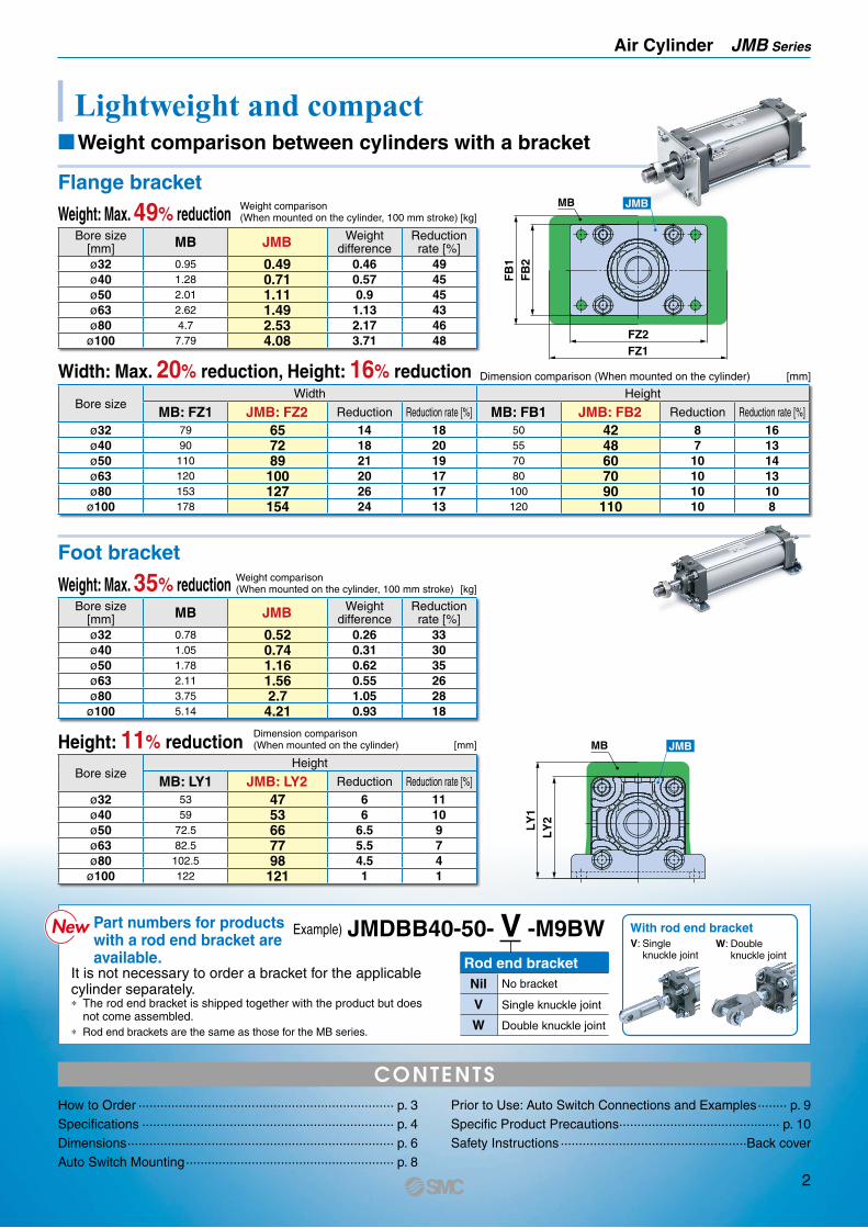
Lightweight and compact
Flange bracket
Bore size[mm] MB JMB Weight
differenceReduction rate [%]
ø32 0.95 0.49 0.46 49ø40 1.28 0.71 0.57 45ø50 2.01 1.11 0.9 45ø63 2.62 1.49 1.13 43ø80 4.7 2.53 2.17 46
ø100 7.79 4.08 3.71 48
Bore size[mm] MB JMB Weight
differenceReduction rate [%]
ø32 0.78 0.52 0.26 33ø40 1.05 0.74 0.31 30ø50 1.78 1.16 0.62 35ø63 2.11 1.56 0.55 26ø80 3.75 2.7 1.05 28ø100 5.14 4.21 0.93 18
Bore sizeWidth Height
MB: FZ1 JMB: FZ2 Reduction Reduction rate [%] MB: FB1 JMB: FB2 Reduction Reduction rate [%]
ø32 79 65 14 18 50 42 8 16ø40 90 72 18 20 55 48 7 13ø50 110 89 21 19 70 60 10 14ø63 120 100 20 17 80 70 10 13ø80 153 127 26 17 100 90 10 10
ø100 178 154 24 13 120 110 10 8
Bore sizeHeight
MB: LY1 JMB: LY2 Reduction Reduction rate [%]
ø32 53 47 6 11ø40 59 53 6 10ø50 72.5 66 6.5 9ø63 82.5 77 5.5 7ø80 102.5 98 4.5 4ø100 122 121 1 1
Weight: Max. 35% reduction
Width: Max. 20% reduction, Height: 16% reduction
Height: 11% reduction
Weight comparison(When mounted on the cylinder, 100 mm stroke) [kg]
Weight comparison(When mounted on the cylinder, 100 mm stroke) [kg]
Dimension comparison (When mounted on the cylinder) [mm]
Dimension comparison(When mounted on the cylinder) [mm]
FZ1FZ2
FB
2F
B1
MB JMB
LY
2L
Y1
MB JMB
How to Order ······································································ p. 3Specifications ····································································· p. 4Dimensions ········································································· p. 6Auto Switch Mounting ························································· p. 8
Prior to Use: Auto Switch Connections and Examples ········ p. 9Specific Product Precautions ············································ p. 10Safety Instructions ···················································Back cover
Part numbers for products with a rod end bracket are available.
It is not necessary to order a bracket for the applicable cylinder separately.* The rod end bracket is shipped together with the product but does
not come assembled.
Example) JMDBB40-50- V -M9BW With rod end bracket
Rod end bracketNil No bracket
V Single knuckle joint
W Double knuckle joint* Rod end brackets are the same as those for the MB series.
NewNew
Weight: Max. 49% reduction
CONTENTS
V: Single knuckle joint
W: Double knuckle joint
Foot bracket
MWeight comparison between cylinders with a bracket
2

∗1 Water-resistant type auto switches can be mounted on the above models, but SMC cannot guarantee water resistance. Please contact SMC regarding water-resistant types with the above model numbers.
∗ Lead wire length symbols: 0.5 m………… Nil (Example) M9NW ∗ Solid state auto switches marked with “v” are produced upon receipt of order. 1 m………… M (Example) M9NWM 3 m………… L (Example) M9NWL 5 m………… Z (Example) M9NWZ∗ For details on auto switches with pre-wired connectors, refer to the Web Catalog.∗ Auto switches and auto switch mounting brackets are shipped together with the product but do not come assembled.
Applicable Auto Switches/Refer to the Web Catalog for further information on auto switches.
Type Special functionElectrical
entry
Indica
tor lig
ht
Wiring(Output)
Load voltage Auto switch model Lead wire length [m] Pre-wired connector
Applicable loadDC AC Perpendicular In-line
0.5(Nil)
1(M)
3(L)
5(Z)
So
lid s
tate
au
to s
wit
ch —
Grommet Yes
3-wire (NPN)
24 V
5 V, 12 V
—
M9NV M9N V V V v v ICcircuit
Relay, PLC
3-wire (PNP) M9PV M9P V V V v v
2-wire 12 V M9BV M9B V V V v v —
Diagnostic indication(2-color indicator)
3-wire (NPN) 5 V, 12 V
M9NWV M9NW V V V v v ICcircuit3-wire (PNP) M9PWV M9PW V V V v v
2-wire 12 V M9BWV M9BW V V V v v —
Water resistant(2-color indicator)
3-wire (NPN) 5 V, 12 V
M9NAV∗1 M9NA∗1 v v V v v ICcircuit3-wire (PNP) M9PAV∗1 M9PA∗1 v v V v v
2-wire 12 V M9BAV∗1 M9BA∗1 v v V v v —
How to Order
With auto switch JMDB
With auto switch (Built-in magnet)∗ Not available without a magnet
Refer to page 4 for standard strokes.
Cylinder stroke [mm]
Auto switch
∗ For applicable auto switches, refer to the table below.
Nil Without auto switch
Number of auto switchesNil 2S 13 3n n
Bore size32 32 mm40 40 mm45 45 mm50 50 mm56 56 mm63 63 mm67 67 mm80 80 mm85 85 mm100 100 mm
MountingB BasicL Axial footF Rod flangeG Head flange
∗ “L,” “F,” and “G” cannot be selected for bore sizes ø45, ø56, ø67, and ø85.
Nil RcTN NPTTF G
Port thread type
Rod end bracketNil No bracketV Single knuckle jointW Double knuckle joint
∗ A knuckle joint pin is not provided with the single knuckle joint.
∗ The rod end bracket is shipped together with the product.
B 5032 M9BW
Air CylinderDouble Acting, Single Rod
JMB Seriesø32, ø40, ø45, ø50, ø56, ø63, ø67, ø80, ø85, ø100
3

4
Air CylinderDouble Acting, Single Rod JMB Series
OUT IN
Refer to page 8 for cylinders with auto switches.
· Auto Switch Proper Mounting Position (Detection at stroke end) and Mounting Height
· Minimum Stroke for Auto Switch Mounting· Operating Range· Auto Switch Mounting Brackets/Part Nos.
Bore size [mm]
Rod size [mm]
Operating direction
Piston area [mm2]
Operating pressure [MPa] 0.2 0.3 0.4 0.5 0.6 0.7
32 10OUT 804 161 241 322 402 483 563
IN 726 145 218 290 363 435 508
40 14OUT 1257 251 377 503 628 754 880
IN 1103 221 331 441 551 662 772
45 14OUT 1590 318 477 636 795 954 1113
IN 1436 287 431 575 718 862 1006
50 18OUT 1963 393 589 785 982 1178 1374
IN 1709 342 513 684 855 1025 1196
56 18OUT 2463 493 739 985 1232 1478 1724
IN 2209 442 663 883 1104 1325 1546
63 18OUT 3117 623 935 1247 1559 1870 2182
IN 2863 573 859 1145 1431 1718 2004
67 18OUT 3526 705 1058 1410 1763 2115 2468
IN 3271 654 981 1308 1636 1963 2290
80 22OUT 5027 1005 1508 2011 2513 3016 3519
IN 4646 929 1394 1859 2323 2788 3252
85 22OUT 5675 1135 1702 2270 2837 3405 3972
IN 5294 1059 1588 2118 2647 3177 3706
100 26OUT 7854 1571 2356 3142 3927 4712 5498
IN 7323 1465 2197 2929 3662 4394 5126
[Unit: N]
* Theoretical output [N] = Pressure [MPa] x Piston area [mm2]
Theoretical Output
Bore size [mm] Standard stroke [mm] Max. manufacturable
stroke32 25, 50, 75, 100, 125, 150, 175, 200, 250, 300 30040 25, 50, 75, 100, 125, 150, 175, 200, 250, 300 30045 25, 50, 75, 100, 125, 150, 175, 200, 250, 300 30050 25, 50, 75, 100, 125, 150, 175, 200, 250, 300, 350, 400 40056 25, 50, 75, 100, 125, 150, 175, 200, 250, 300, 350, 400 40063 25, 50, 75, 100, 125, 150, 175, 200, 250, 300, 350, 400 40067 25, 50, 75, 100, 125, 150, 175, 200, 250, 300, 350, 400 40080 25, 50, 75, 100, 125, 150, 175, 200, 250, 300, 350, 400, 450, 500 50085 25, 50, 75, 100, 125, 150, 175, 200, 250, 300, 350, 400, 450, 500 500
100 25, 50, 75, 100, 125, 150, 175, 200, 250, 300, 350, 400, 450, 500 500
Standard Strokes
Bore size [mm] 32 40 45 50 56 63 67 80 85 100Action Double acting, Single rodFluid AirProof pressure 1.0 MPaMax. operating pressure 0.7 MPa*2
Min. operating pressure 0.05 MPaAmbient and fluid temperatures 5 to 60°CLubrication Not required (Non-lube)Piston speed*1 50 to 500 mm/s*2
Stroke length tolerance +2.0 0
Cushion Non-adjustable air cushion + rubber bumperPort size (Rc, NPT, G) 1/8 1/4 3/8Mounting Basic
Specifications
PrecautionsBe sure to read this before han-dling the products. Refer to the back cover for safety instruc-tions. For actuator and auto switch precautions, refer to the “Handling Precautions for SMC Products” and the “Operation Manual” on the SMC website: https://www.smcworld.com
*1 Depending on the system configuration selected, the specified speed may not be satisfied.*2 Max. operating pressure and piston speed are different from those of the existing model (MB series).

5
JMB Series
ø100
ø85
ø80ø67
ø63ø56ø50ø45ø40
ø32
3
10
100
1000
50030010050
40
Maximum speed [mm/s]
Load
mas
s [k
g]
ø100
ø85
ø80
ø67
ø63
ø56
ø50ø45
ø40
ø32
1
10
100
500200100 4003000
Allo
wab
le la
tera
l loa
d at
rod
end
[N]
Cylinder stroke [mm]
Example) Load limit at rod end when the air cylinder ø50 is actuated at 300 mm/sExtend upward from 300 mm/s on the horizontal axis of the graph to the intersection point with the line for a tube bore size of 50 mm, and then extend leftward from this point to find the load of 40 kg.
Allowable Kinetic Energy Allowable Lateral Load at Rod End
[kg]
Weight
Calculation example) JMDBL50-100¡Basic weight ··················· 0.62 (Basic, ø50)¡Additional weight ············ 0.19/50 mm stroke¡Stroke ····························· 100 mm stroke¡Foot bracket (2 pcs.) ······· 0.08 x 2 0.62 + (0.19 x 100/50) + (0.08 x 2) = 1.16 kg
Bore size [mm] 32 40 45 50 56 63 67 80 85 100Basic weight Basic 0.21 0.30 0.32 0.62 0.69 0.88 1.03 1.54 1.91 2.56
Additional weight per 50 mm of stroke 0.11 0.17 0.18 0.19 0.20 0.20 0.24 0.32 0.38 0.46Additional weight for
mounting bracketFoot bracket 0.04 0.05 — 0.08 — 0.14 — 0.26 — 0.36Flange bracket 0.06 0.07 — 0.11 — 0.21 — 0.35 — 0.60
AccessoriesSingle knuckle joint 0.15 0.23 0.23 0.26 0.26 0.26 0.26 0.60 0.60 0.83Double knuckle joint (with pin) 0.22 0.37 0.37 0.43 0.43 0.43 0.43 0.87 0.87 1.27
Mounting Brackets/Part Nos.
Mounting bracketMin. order quantity
Bore size [mm]Contents32 40 45 50 56 63 67 80 85 100
Foot bracket*1 2 JMB-L032 JMB-L040 — JMB-L050 — JMB-L063 — JMB-L080 — JMB-L1001 foot bracket, 2 hexagon nuts,
2 flat washers
Flange bracket 1 JMB-F032 JMB-F040 — JMB-F050 — JMB-F063 — JMB-F080 — JMB-F1001 flange bracket, 4 hexagon
nuts, 4 flat washersSingle knuckle joint 1 I-03M I-04M I-05M I-08M I-10M 1 single knuckle joint
Double knuckle joint 1 Y-03M Y-04M Y-05M Y-08M Y-10M1 double knuckle joint, 1 pin,
2 split pins, 2 flat washers
*1 Order two foot brackets per cylinder.
Mounting Brackets/Material, Surface Treatment
Segment Description Material Surface treatment
Mounting bracketsFoot bracket Carbon steel Zinc chromatingFlange bracket Carbon steel Zinc chromating
AccessoriesSingle knuckle joint Free cutting carbon steel Zinc chromatingDouble knuckle joint Cast iron Metallic silver color paintingKnuckle joint pin Carbon steel (None)

6
Air CylinderDouble Acting, Single Rod JMB Series
øD
G G
BCB1
BC4 x J
øE
MMWidth acrossflats KA 2 x P
(Rc, NPT, G)
H1
ALA NF
HZZ + Stroke
S + Stroke
NM
K
B
C
d
D
H
30°
Bore size Stroke range A AL B B1 C D E F G H H1 J K KA M MM N P S ZZ32 Up to 300 22 19.5 42 17 31 10 24 8 9 38 6 M5 x 0.8 5.5 8 8 M10 x 1.25 18 1/8 63 10940 Up to 300 24 21 48 22 37 14 32 9 9 44 8 M5 x 0.8 8 12 8 M14 x 1.5 18 1/8 62 11445 Up to 300 24 21 52 22 41 14 32 9 9 44 8 M5 x 0.8 8 12 8 M14 x 1.5 18 1/8 62 11450 Up to 400 35 32 60 27 45 18 38 10 9 55 11 M6 x 1 7 16 11 M18 x 1.5 18 1/8 63 12956 Up to 400 35 32 65 27 50 18 38 10 9 55 11 M6 x 1 7 16 11 M18 x 1.5 18 1/8 63 12963 Up to 400 35 32 70 27 55 18 38 6 11 51 11 M6 x 1 7 16 11 M18 x 1.5 22 1/4 73 13567 Up to 400 35 32 75 27 58 18 38 6 11 51 11 M8 x 1.25 7 16 11 M18 x 1.5 22 1/4 73 13580 Up to 500 40 37 88 32 69 22 45 12 13 62 13 M8 x 1.25 7 19 13 M22 x 1.5 26 1/4 83 15885 Up to 500 40 37 95 32 74 22 45 12 13 62 13 M10 x 1.25 7 19 14 M22 x 1.5 26 1/4 83 159100 Up to 500 40 37 110 41 87 26 50 10 14 66 16 M10 x 1.25 12 23 14 M26 x 1.5 28 3/8 88 168
Basic: JMDBB
Dimensions
Rod end nut (Standard)
Part no. Bore size d H B C DNT-03 32 M10 x 1.25 6 17 19.6 16.5NT-04 40, 45 M14 x 1.5 8 22 25.4 21NT-05 50, 56, 63, 67 M18 x 1.5 11 27 31.2 26NT-08 80, 85 M22 x 1.5 13 32 37.0 31NT-10 100 M26 x 1.5 16 41 47.3 39
[mm]
[mm]

7
JMB Series
LZLX
LY
LH
4 x øLD X LS + Stroke XYL
TY
4 x øFD
FBFY
FZFX
FT
FT FZFX
FBFY
4 x øFD
Axial foot: JMBL
Rod flange: JMBF
Head flange: JMBG
Dimensions
[mm]
Bore size LD LH LS LT LX LY LZ X Y32 5.5 26 46 3.2 52 47 64 12 6.340 5.5 29 44 3.2 58 53 69 12 5.550 6.5 36 41 3.2 75 66 90 14 6.863 6.5 42 51 4.5 86 77 100 16 7.580 9 54 55 4.5 114 98 136 19 10
100 11 66 56 4.5 138 121 160 20.5 11.5
[mm]
Bore size FB FD FT FX FY FZ32 42 5.5 3.2 54 31 6540 48 5.5 3.2 60 37 7250 60 6.5 3.2 74 46 8963 70 6.5 4.5 85 55 10080 90 9 4.5 108 70 127
100 110 11 5 133 87 154

8
A
B
≈ Hs
≈ H
tD-M9m/M9mVD-M9mW/M9mWVD-M9mA/M9mAV
<Tie-rod mounting>
JMB Series
Auto Switch Mounting
Auto Switch Proper Mounting Position (Detection at stroke end) and Mounting Height
Minimum Stroke for Auto Switch Mounting
[mm]Auto Switch Proper Mounting Position [mm]Auto Switch Mounting Height
* Adjust the auto switch after confirming the operating conditions in the actual setting.
Auto switchmodel
Bore size
D-M9m/M9mVD-M9mW/M9mWVD-M9mA/M9mAV
A B32 7.5 740 6.5 745 6.5 750 7 6.556 7 6.563 8 867 8 880 9 985 9 9100 9 10
Auto switch model
Bore size
D-M9m/M9mVD-M9mW/M9mWVD-M9mA/M9mAV
32 3.540 445 450 456 4.563 567 4.580 585 5.5
100 5.5
* Values which include hysteresis are for reference purposes only. They are not a guarantee (assuming approximately ±30% dispersion) and may change substantially depending on the ambient environment.
Auto switch model
Bore size
D-M9m/M9mVD-M9mW/M9mWVD-M9mA/M9mAV
32 BMB10-03240 BMB10-03245 BMB10-03250 BMB5-03256 BMB5-03263 BMB5-03267 BA7-04080 BA7-04085 BA7-063100 BA7-063
Auto switchmodel
Bore size
D-M9mD-M9mWD-M9mA
D-M9mVD-M9mWVD-M9mAV
Hs Ht Hs Ht32 24.5 22.5 30.5 22.540 28.5 25.5 34 25.545 30.5 27.5 36 27.550 33 30 38.5 3056 35 32.5 41 32.563 38.5 36 43 3667 45.5 45 49.5 4580 46.5 45 52 4585 54 53.5 57.5 53.5
100 54 53.5 59.5 53.5
n: Number of auto switches [mm]
*1 When “n” is an odd number, an even number that is one larger than the odd number is to be used for the calculation.
Auto switch model Number of auto switches ø32, ø40, ø45, ø50, ø56, ø63, ø67, ø80, ø85, ø100
D-M9mD-M9mW
2 (Different surfaces, Same surface), 1
15
n 15 + 40 (n − 2)2
(n = 2, 4, 6, 8…)*1
D-M9mVD-M9mWV
2 (Different surfaces, Same surface), 1
10
n 10 + 30 (n − 2)2
(n = 2, 4, 6, 8…)*1
D-M9mA
2 (Different surfaces, Same surface), 1
15
n 15 + 40 (n − 2)2
(n = 2, 4, 6, 8…)*1
D-M9mAV
2 (Different surfaces, Same surface), 1
15
n 15 + 30 (n − 2)2
(n = 2, 4, 6, 8…)*1
Auto Switch Mounting Brackets/Part Nos.
Operating Range
[mm]
[mm]
[Stainless Steel Mounting Screw Kit]The following stainless steel mounting screw kit (including set screws) is available. Use it in accordance with the operating environment. (Since the auto switch mounting bracket is not included, order it separately.)
* When using the D-M9mA(V), do not use the steel set screws which are inc luded wi th the auto swi tch mounting brackets shown to the left (BMB10-032, BMB5-032, BA7-040, BA7-063). Order a stainless steel screw kit (BBA1) separately, and use the M4 x 6 L stainless steel set screws included in the BBA1.

Relay
RelayLoad
Load
Load
Load Load
Load Load
Load
Blue
Black
Brown
Auto switch 2
Blue
Black
Brown
Auto switch 1
Blue
Black
Brown
Auto switch 2
Blue
Black
Brown
Auto switch 1
Blue
Black
Brown
Auto switch 2
Blue
Black
Brown
Auto switch 1
Blue
Black
Brown
Auto switch 2
Blue
Black
Brown
Auto switch 1
Blue
Brown
Auto switch 2
Blue
Brown
Auto switch 1
Blue
Black
Brown
Auto switch 2
Blue
Black
Brown
Auto switch 1
Blue
Brown
Auto switch 2
Blue
Brown
Auto switch 1
Blue
Black
Brown
Auto switch 2
Blue
Black
Brown
Auto switch 1
Input
COM
COMCOM
COM
InputInput
Input
Blue
Brown
Blue
Brown
Blue
Black
Brown
Blue
Black
Brown
Auto switch
Auto switch
Auto switch
Auto switch
Connect according to the applicable PLC input specifications, as the connection method will vary depending on the PLC input specifications.
Because there is no current leakage, the load voltage will not increase when turned OFF. However, depending on the number of auto switches in the ON state, the indicator lights may sometimes grow dim or not light up, due to the dispersion and reduction of the current flowing to the auto switches.
When two auto switches are connected in parallel, malfunction may occur because the load voltage will increase when in the OFF state.Auto switches with a load
voltage less than 20 V cannot be used. Please contact SMC if using AND connection for a heat-resistant solid state auto switch or a trimmer switch.
When two auto switches are connected in series, a load may malfunction because the load voltage will decline when in the ON state.The indicator lights will light up when both of the auto switches are in the ON state.
(Reed)(Solid state)
Example) Load voltage at OFFLeakage current: 1 mALoad impedance: 3 kΩLoad voltage at OFF = Leakage current x 2 pcs. x
Load impedance= 1 mA x 2 pcs. x 3 kΩ= 6 V
Example) Load voltage at ONPower supply voltage: 24 VDCInternal voltage drop: 4 VLoad voltage at ON = Power supply voltage –
Internal voltage drop x 2 pcs.= 24 V − 4 V x 2 pcs.= 16 V
Prior to UseAuto Switch Connections and Examples
3-wire, NPN
2-wire
3-wire, PNP
2-wire
(PLC internal circuit)
(PLC internal circuit)
(PLC internal circuit)
(PLC internal circuit)
3-wire AND connection for NPN output(Using relays) (Performed with auto switches only)
3-wire OR connection for NPN output
3-wire AND connection for PNP output(Using relays) (Performed with auto switches only)
3-wire OR connection for PNP output
2-wire AND connection 2-wire OR connection
Sink Input Specifications
Examples of AND (Series) and OR (Parallel) Connections
Source Input Specifications
* When using solid state auto switches, ensure the application is set up so the signals for the first 50 ms are invalid. Depending on the operating environment, the product may not operate properly.
9

Mounting
Caution1. Allowable lateral load
Lateral load that can apply to the piston rod end is limited. If a cylinder is used with a lateral load over the limit, it may cause air leakage due to abnormal friction of seals, galling of cylinder tubes and pistons, or abnormal friction of the bearing part. The lateral load applied to the piston rod must be within the allowable range indicated in this catalog. When the load exceeds the limit, install a guide or change the bore size to suit the load in order to make the load within the allowable range.
2. Connection with a workpieceWhen a workpiece is mounted on the piston rod end, connect them aligning the center of piston rod and a workpiece. If they are off-center, lateral load is generated and phenomena mentioned in 1. may occur. In order not to apply the off-center load, use of a floating joint is recommended.
3. Use the tightening torques shown below when replacing mounting brackets.
Bore size [mm] Tightening torque [N·m]
32, 40 1.79 to 2.42
50, 63 3.09 to 4.19
80 6.38 to 8.63
100 12.5 to 16.91
4. When replacing the mounting bracket, the tie-rod tightening nut on the cylinder body may also loosen.After retightening the tie-rod tightening nut with the proper tightening torque (refer to 3. above), install the mounting bracket.
5. Simultaneous use of multiple cylindersIt is difficult to control the speed of pneumatic cylinders. The following conditions cause speed change: change in supply pressure, load, temperature and lubrication, performance difference of each cylinder, deterioration of each part over time, etc. Speed controller can be used to control the speed of multiple cylinders simultaneously for a short period of time, but depending on conditions, it may not work as desired. If multiple cylinders cannot operate simultaneously, unreasonable force is applied to the piston rod because cylinder positions may not be the same. This may cause abnormal friction of seals and bearings, and galling of cylinder tubes and pistons. Do not use an application to operate several cylinders simultaneously by adjusting cylinder speed. If this is inevitable, use a high rigid guide against load, so that the cylinder is not damaged even when the each cylinder output is slightly different.
6. Depending on the system configuration selected, the specified speed may not be satisfied.
Be sure to read this before handling the products. Refer to the back cover for safety instruc-tions. For actuator and auto switch precautions, refer to the “Handling Precautions for SMC Products” and the “Operation Manual” on the SMC website: https://www.smcworld.com
JMB SeriesSpecific Product Precautions
10

∗ The “Allowable Lateral Load at Rod End” graph has been changed. TQ
∗ Bore sizes ø63, ø67, ø80, ø85, and ø100 have been added. TR
∗ Port thread types NPT and G have been added. UR
∗ An axial foot type and a flange type have been added to mounting brackets.∗ Number of pages has been increased from 12 to 16. ZT
Revision History
Edition B
Edition C
Edition D
Edition E
Safety Instructions Be sure to read the “Handling Precautions for SMC Products” (M-E03-3) and “Operation Manual” before use.
CautionSMC products are not intended for use as instruments for legal metrology.Measurement instruments that SMC manufactures or sells have not been qualified by type approval tests relevant to the metrology (measurement) laws of each country. Therefore, SMC products cannot be used for business or certification ordained by the metrology (measurement) laws of each country.
Compliance Requirements
∗1) ISO 4414: Pneumatic fluid power – General rules relating to systems. ISO 4413: Hydraulic fluid power – General rules relating to systems. IEC 60204-1: Safety of machinery – Electrical equipment of machines. (Part 1: General requirements) ISO 10218-1: Manipulating industrial robots – Safety. etc.
Caution indicates a hazard with a low level of risk which, if not avoided, could result in minor or moderate injury.Caution:Warning indicates a hazard with a medium level of risk which, if not avoided, could result in death or serious injury.Warning:
Danger : Danger indicates a hazard with a high level of risk which, if not avoided, will result in death or serious injury.
Warning Caution1. The compatibility of the product is the responsibility of the
person who designs the equipment or decides its specifications.Since the product specified here is used under various operating conditions, its compatibility with specific equipment must be decided by the person who designs the equipment or decides its specifications based on necessary analysis and test results. The expected performance and safety assurance of the equipment will be the responsibility of the person who has determined its compatibility with the product. This person should also continuously review all specifications of the product referring to its latest catalog information, with a view to giving due consideration to any possibility of equipment failure when configuring the equipment.
2. Only personnel with appropriate training should operate machinery and equipment.The product specified here may become unsafe if handled incorrectly. The assembly, operation and maintenance of machines or equipment including our products must be performed by an operator who is appropriately trained and experienced.
3. Do not service or attempt to remove product and machinery/equipment until safety is confirmed.1. The inspection and maintenance of machinery/equipment should only be
performed after measures to prevent falling or runaway of the driven objects have been confirmed.
2. When the product is to be removed, confirm that the safety measures as mentioned above are implemented and the power from any appropriate source is cut, and read and understand the specific product precautions of all relevant products carefully.
3. Before machinery/equipment is restarted, take measures to prevent unexpected operation and malfunction.
4. Contact SMC beforehand and take special consideration of safety measures if the product is to be used in any of the following conditions. 1. Conditions and environments outside of the given specifications, or use
outdoors or in a place exposed to direct sunlight.2. Installation on equipment in conjunction with atomic energy, railways, air
navigation, space, shipping, vehicles, military, medical treatment, combustion and recreation, or equipment in contact with food and beverages, emergency stop circuits, clutch and brake circuits in press applications, safety equipment or other applications unsuitable for the standard specifications described in the product catalog.
3. An application which could have negative effects on people, property, or animals requiring special safety analysis.
4. Use in an interlock circuit, which requires the provision of double interlock for possible failure by using a mechanical protective function, and periodical checks to confirm proper operation.
1. The product is provided for use in manufacturing industries.The product herein described is basically provided for peaceful use in manufacturing industries. If considering using the product in other industries, consult SMC beforehand and exchange specifications or a contract if necessary. If anything is unclear, contact your nearest sales branch.
Limited warranty and Disclaimer/Compliance RequirementsThe product used is subject to the following “Limited warranty and Disclaimer” and “Compliance Requirements”.Read and accept them before using the product.
Limited warranty and Disclaimer1. The warranty period of the product is 1 year in service or 1.5 years after
the product is delivered, whichever is first.∗2)
Also, the product may have specified durability, running distance or replacement parts. Please consult your nearest sales branch.
2. For any failure or damage reported within the warranty period which is clearly our responsibility, a replacement product or necessary parts will be provided. This limited warranty applies only to our product independently, and not to any other damage incurred due to the failure of the product.
3. Prior to using SMC products, please read and understand the warranty terms and disclaimers noted in the specified catalog for the particular products.
∗2) Vacuum pads are excluded from this 1 year warranty.A vacuum pad is a consumable part, so it is warranted for a year after it is delivered. Also, even within the warranty period, the wear of a product due to the use of the vacuum pad or failure due to the deterioration of rubber material are not covered by the limited warranty.
1. The use of SMC products with production equipment for the manufacture of weapons of mass destruction (WMD) or any other weapon is strictly prohibited.
2. The exports of SMC products or technology from one country to another are governed by the relevant security laws and regulations of the countries involved in the transaction. Prior to the shipment of a SMC product to another country, assure that all local rules governing that export are known and followed.
These safety instructions are intended to prevent hazardous situations and/or equipment damage. These instructions indicate the level of potential hazard with the labels of “Caution,” “Warning” or “Danger.” They are all important notes for safety and must be followed in addition to International Standards (ISO/IEC)∗1), and other safety regulations.
Safety Instructions
Related Documents