45 10. HENRIE, J.O. Properties of Nuclear Shielding Concrete. Journal of the American Concrete Institute. July 1959. 11. ITO, N. and YANAGAWA, A. Method for Manufacturing High Boron Concrete for Radiation Protection. Japanese Patent No. 43-11793, May 1983. 12. BS 4975 : 1973, Specification for Prestressed Concrete Pressure Vessels for Nuclear Reactors, British Standards Institution. 13. GREGORY, A.R. CEGB Proof of Evidence on Decommissioning. Sizewell 'B' Power Station Public Enquiry. November 1982. 14. NUREG, CR 0130. Technology, Safety and Costs for Decommissioning of a Reference Pressurised Water Reactor. U.S. Nuclear Regulatory Commission. June 1978. 11. ACKNOWLEDGEMENTS On behalf of Taylor Woodrow Construction Limited, the authors gratefully acknowledge the financial and technical support afforded to them during the study by the Commission of the European Communities, the Nuclear Installations Inspectorate, the Central Electricity Generating Board, the National Nuclear Corporation Limited and the Department of the Environment. Thanks is also given to the Central Electricity Generating Board for its permission to reproduce figures nos. 1, 2, 3, 4 and 8. The authors also acknowledge the help given to them by their colleagues in carrying out the work and preparing the report. 12. TABLES AND FIGURES Table 1 Table 2 Figure 1 2 3 4 5 6 7 8 9 Results of ultimate load analysis of structures having planes of weakness. Comparison of activity levels in PWR for 10 year and 100 year decay times. Site plan - typical magnox station. Section through typical magnox station. Site plan - typical AGR station. Section through typical AGR station. Section through Hartlepool/Heysham I multicavity reactor vessel. Section through Heysham II/Torness single cavity reactor vessel. Assumed activated zone of a typical AGR prestressed concrete pressure vessel. Variation of average permissible access times inside vessel (with core intact) and dose equivalent rate, with time after shutdown. View on outside face of a typical PCRV liner.

Welcome message from author
This document is posted to help you gain knowledge. Please leave a comment to let me know what you think about it! Share it to your friends and learn new things together.
Transcript

45
10. HENRIE, J.O. Properties of Nuclear Shielding Concrete. Journal of the American Concrete Institute. July 1959.
11. ITO, N. and YANAGAWA, A. Method for Manufacturing High Boron Concrete for Radiation Protection. Japanese Patent No. 43-11793, May 1983.
12. BS 4975 : 1973, Specification for Prestressed Concrete Pressure Vessels for Nuclear Reactors, British Standards Institution.
13. GREGORY, A.R. CEGB Proof of Evidence on Decommissioning. Sizewell 'B' Power Station Public Enquiry. November 1982.
14. NUREG, CR 0130. Technology, Safety and Costs for Decommissioning of a Reference Pressurised Water Reactor. U.S. Nuclear Regulatory Commission. June 1978.
11. ACKNOWLEDGEMENTS
On behalf of Taylor Woodrow Construction Limited, the authors gratefully acknowledge the financial and technical support afforded to them during the study by the Commission of the European Communities, the Nuclear Installations Inspectorate, the Central Electricity Generating Board, the National Nuclear Corporation Limited and the Department of the Environment. Thanks is also given to the Central Electricity Generating Board for its permission to reproduce figures nos. 1, 2, 3, 4 and 8.
The authors also acknowledge the help given to them by their colleagues in carrying out the work and preparing the report.
12. TABLES AND FIGURES
Table 1
Table 2
Figure 1 2 3 4 5
6
7
8
9
Results of ultimate load analysis of structures having planes of weakness. Comparison of activity levels in PWR for 10 year and 100 year decay times.
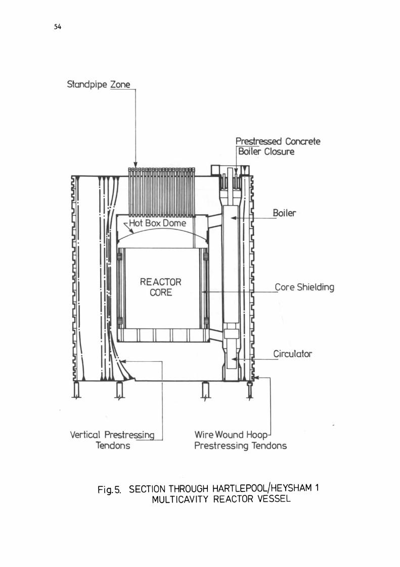
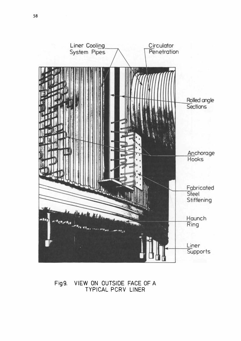
Site plan - typical magnox station. Section through typical magnox station. Site plan - typical AGR station. Section through typical AGR station. Section through Hartlepool/Heysham I multicavity reactor vessel. Section through Heysham II/Torness single cavity reactor vessel. Assumed activated zone of a typical AGR prestressed concrete pressure vessel. Variation of average permissible access times inside vessel (with core intact) and dose equivalent rate, with time after shutdown. View on outside face of a typical PCRV liner.

46
10 Section through typical PCRV showing main internal structures and items.
11 Proposed arrangement of planes of weakness in the activated zone of a prestressed concrete pressure vessel.
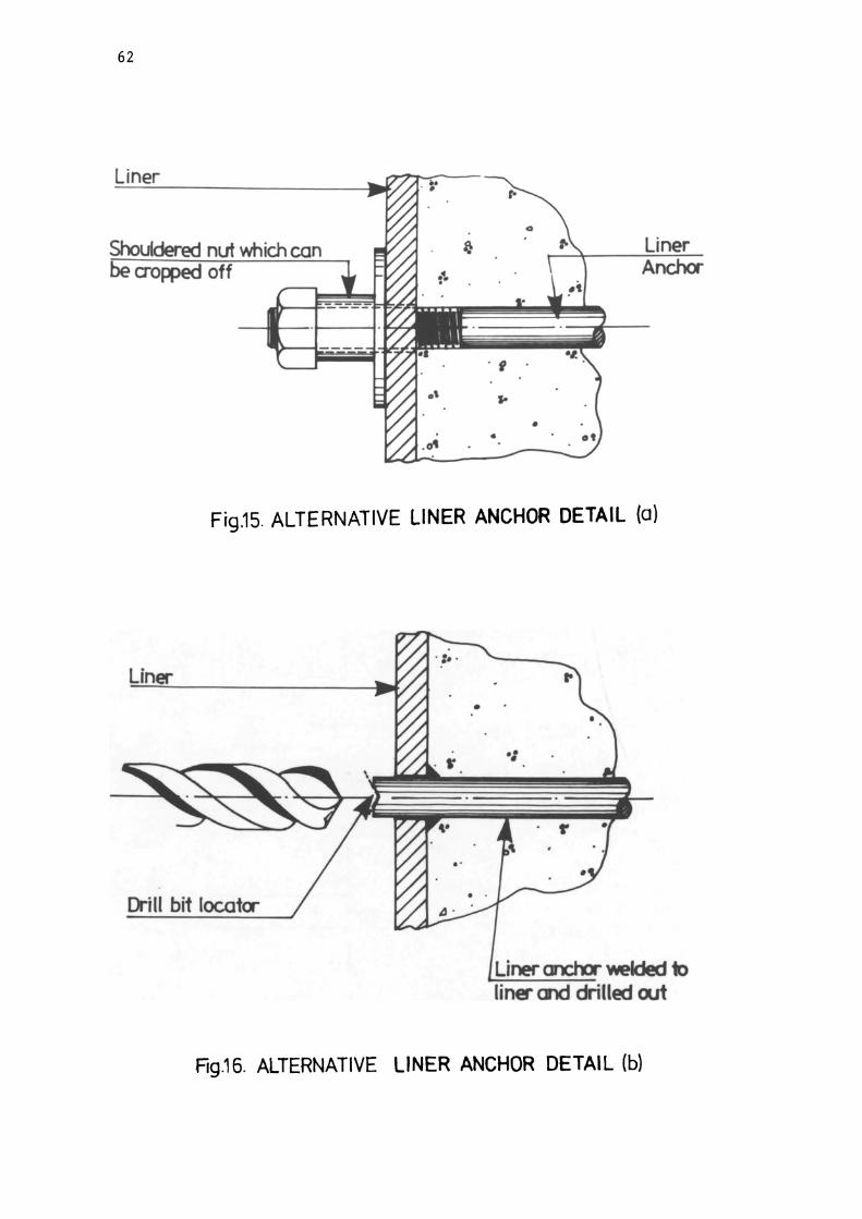
12 Planes of hollow tubes. 13 Crack inducer slots. 14 Preformed cavities. 15 Alternative liner anchor detail (a). 16 Alternative liner anchor detail (b). 17 Possible detail to facilitate removal of penetration end
attached to main liner. 18 Grouped and debondedpenetrations. 19 Planes of weakness analysis - structure type 1. 20 Planes of weakness analysis - structure type 2. 21 Finite element grid for assessment of structural effects of
planes of weakness. 22 Planes of weakness analysis - location of stress profile
control points. 23 to 25 Typical comparison of D.R. and F.E.
Analyses of structure Type 1. 26 Stress profiles for structures type 1 and 2, Load Case 1,
Profile 6, Vertical. 27 Stress profiles for structures type 1 and 2, Load Case 1,
Profile 7, Vertical. 28 Stress profiles for structures type 1 and 2, Load Case 1,
Profile 2, Radial. 29 Stress profiles for structures type 1 and 2, Load Case 1,
Profile 7, Radial. 30 Stress profiles for structures type 1 and 2, Load Case 1,
Profile 2, Hoop. 31 Stress profiles for structures type 1 and 2, Load Case 1,
Profile 7, Hoop. 32 Stress profiles for structures type 1 and 2, Load Case 2,
Profile 6, Vertical. 33 Stress profiles for structures type 1 and 2, Load Case 2,
Profile 7, Vertical. 34 Stress profiles for structures type 1 and 2, Load Case 2,
Profile 2, Radial. 35 Stress profiles for structures type 1 and 2, Load Case 2,
Profile 7, Radial. 36 Stress profiles for structures type 1 and 2, Load Case 2,
Profile 2, Hoop. 37 Stress profiles for structures type 1 and 2, Load Case 2,
Profile 7, Hoop. 38 In-situ construction formation of planes of weakness within
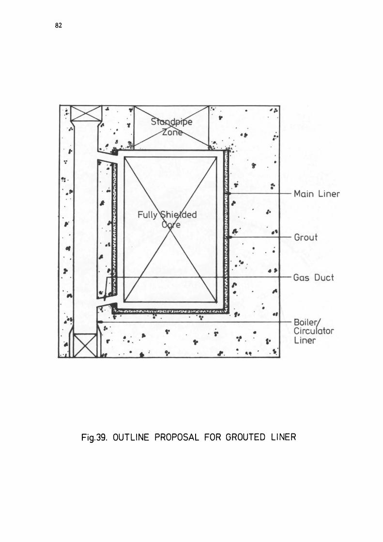
a normal sized pour. 39 Outline proposal for grouted liner. 40 Proposed detail of junction between grouted main liner and
gas duct. 41 Outline scheme for removal of standpipe region to give
access for removal of reactor core and internals. 42 Site plan - typical PWR station. 43 Major structures of typical PWR station. 44 Reactor building outline of typical PWR station. 45 Reactor building structures of typical PWR station. 46 Nuclear steam supply system of typical PWR. 47 Section through reactor pressure vessel of typical PWR.

47
48 Section through loop pipe penetration of typical PWR pressure vessel.
49 Section through detector slot of typical PWR pressure vessel.
50 Plan showing detector slots of typical PWR pressure vessel.
51 Plan on I.S.I. gallery of typical PWR. 52 Plan on fuelling pool of typical PWR. 53 Section showing possible location for water tanks in PWR
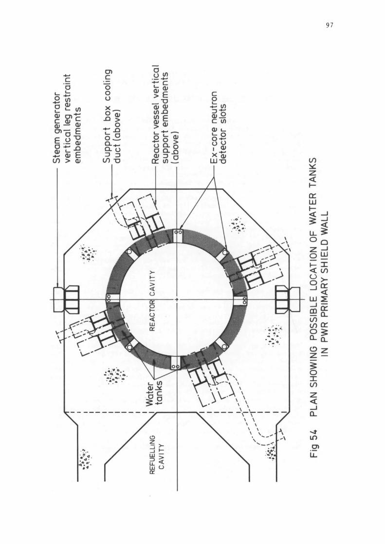
primary shield wall. 54 Plan showing possible location for water tanks in PWR
primary shield wall.

48
TABLE 1
STRUCTURE
Type 1 (No planes of weakness)
Type 2, with all reinforcement outside planes of weakness zone
RESULTS OF ULTIMATE LOAD ANALYSES OF STRUCTURES HAVING PLANES OF WEAKNESS
VESSEL PRESSURE LOAD AT ULTIMATE LOAD FACTOR (p.s.i)
1632 2.534
1624 2.521
Type 2, with haunch 1631 2.533 reinforcement increased by 20%
FAILURE CRITERIA
Longitudinal crack width
Lo ng it ud ina1 crack width
Longitudinal crack width

TABLE 2
COMPONENT
Activated Plant:
reactor internals reactor pressure vessel biological shield
Contaminated Plant:
- in containment:
steam generators primary coolant circuit
COMPARISON OF ACTIVITY LEVELS IN PWR FOR 10 YEAR AND 100 YEAR DECAY TIMES
(Extracted from Ref. 11)
10 YEAR DECAY
MATERIAL MASS TOTAL MEAN (t) ACTIVITY SPECIFIC
(Ci) ACTIVITY (Ci t-1)
stainless steel 210 840000 4000
mild steel 400 1700 4.3 concrete and 600 80 0.13
reinforcement
stainless steel 1250 700 0.56
stainless steel 520 37 0.07
- in other buildings:
auxiliary building steel 145 36 0.25 fuel building steel 12 3 0.25 radwaste building steel 80 25 0.31
Contaminated Structures:
- in containment concrete 1900~ 0.2** 0.0001 - in containment mild steel 670~ 0.6** 0.0009 - in other
buildings concrete 5700~ 0.8** 0.00014 - in other
buildings steel 1100 1.4** 0.0013
Notes:
49
100 YEAR DECAY
TOTAL MEAN ACTI- SPECIFIC VITY ACTIVITY (Ci) (Ci C 1)
110000 520
40 0.1 4 0.01
100 0.08
5 0.009
- -- -- -
0.03** 0.000016 0.08** 0.00012
- -- -
1 * These data refer to the maximum values of the estimated quantity of contaminated concrete surfaces. The minimum quantity may be a factor 50 less.
2 ** These data refer to the maximum values of the estimated activity levels. The minimum levels may be a factor 300 less.
3 No credit is taken in this data for any decontamination operations which may precede decommissioning.

50
0 ;$ 0
: 0 .. • • 0 .. .. • .. • " .. 0 • ;;jls
J ~ i I!, !& .. -0 -1- 0 I .. 0_ ... ... ~
=- .. ~ i .. .. • •
F'\ r-"\ fRI ====
Fig 1. SITE PLAN-TYPICAL MAGNOX STATION

! " :> ! ..
o
\ 11\
J
In
z o ~
~ (/)
X o z (9 <{ 2: -l <{ U a.. >~
I (9 :::J o 0::: I ~
Z o ~ u w (/)
N 01
LL
51

52
D
• 2 • .... -. 1 0 ;-
000 000
Fig3. SITE PLAN-TYPICAL AGR STATION

1---
11
Ito
-
~
CH
""G
E H
"LL
~FUELLIHG .
... C
HIN
E
• h
..
'"" r
11
11·
1
......... G
AL .
.. ,
n n
O':':"
i'\', ,
",
~DI~ ~
.. /:: .
.... ,.:
......
'
'-'-' F
-....
.. I'-"'"'
.-....;~
. S
'''N
DP
IPE
S
T::i:
:.::rr-t:~it-:::::::tII-.
..
. F
UE
L
...•
. ~
. I I
0
:·.f· .
..
RE
.. C
TOIt
H"rrN
G 8
':;~~?:;
, ~II
.:....
,'" ,,'
", <...
... ',,;[
1! I. ,
1M',
1: .
'·; Pltl!-"lt
i:s
afD
~G.id
tE,f:
. Q
5
' .. ;. : ... '.' '.:
'.: .' .:.'
....
:.
. ..
ItE
II V
ItI!
YE
ISE
L
,..
.
d:.j:
::::.. ·::·:·::
'::<.<L
'.'·:;·:b
.. ::.
'~::./.
Fig
4.
SE
CTI
ON
TH
RO
UG
H
TY
PIC
AL
AG
R
STA
TIO
N
VI
W
54
Standpipe Zone
REACTOR CORE
Vertical Presfressin -""""----'
Tendons
Prestressed Concrete Boiler Closure
Boiler ~I-++--~
IHIt---+-----lJ-l--fi;l--~Cor e Sh ield rng
Circulator ~"-+E--~
Wire Wound Hoop Prestressing Tendons
Fig.5. SECTION THROUGH HARTLEPOOLjHEYSHAM 1 MULTICAVITY REACTOR VESSEL

Gas Dcrne
Cere ~ .. l.-Ili.-w-.
Stcndpipe Zale
REACTOR CORE
Fig 6 SECTION THROUGH HEYSHAM HI TORNESS SINGLE CAVITY REACTOR VESSEL
55

56
r---_________ L..., - ~
.................................. .... ...................................................................................... ~\y::::::::::::::::::::::::::::::::::::::::::::::::::::::: ~~
Activated zone ---+ : :w..---up to 1m. thick
..;.:.; I I
.. ,:-1 I .. : .. ....., .......................................................................................................................... .... ................................................................................................................ .... .. .... .......................................... ........ .............. .......................... ...................... .... ..
_ ~~------------._r-~~~~ 1 -4-
Fig 7. ASSUMED ACTIVATED ZONE OF A TYPICAL AG.R. PRESTRESSED CONCRETE PRESSURE VESSEL

---, s::. > ~
E -II -a "--C II -a > :J tr II
II en 0
" a E E a
(!)
1000 Permissible average acces s times
ToP of core
100
Note: Average access times are based on a mean
10 individual exposure of 5 m Sv y.l man - 1 and
a 40 hour wee k.
Gamma dose equivalent 0.1 rate. side of core.
Total 108m Ag
0.01 94 Nb
Contributions from principal isotopes.
0 20 40 60 80 100 120 140 160 180
Time after shutdown (years)
Fig 8. VARIATION OF AVERAGE PERMISSIBLE ACCESS TIMES INSIDE VESSEL (WITH CORE INTACT) AND DOSE EQUIVALENT RATE. WITH TIME
AFTER SHUTDOWN.
57
40 30 20
10 -5 c 0
3 E 2 '-
~ oX CII
0.5 ~ '-~ en '-
0.1 :J 0
.£:. -en II E -0.01 en en ., u u a ., -.0
en en E "-., Q.
., Ot a "-II > c(
58
Circulator netration
I11rtfmtftt+Hm!J-~Rolied angle
Fig9. VIEW ON OUTSIDE FACE OF A TYPICAL PCRV LINER
Sections

rr Boiler-Feed rnd Refu f>e,etrat'ns
Vessel Liner
Man Atxess Penetration
....
r :'1 'I ~ ; I .~
~ . 'T '.' .,
mttm III. II
1 !! j!. 'I ~ II! I,! II I ! ~ i ! ! I i .' • :'J -
,---.tooE :::::=~ ~ III : II! ·I i iU k-2 rr :,..
TI limi il' iii i'v JU , IY I-- -E ~:.::::-.:::
l! I I r--I I --
~ I I
i I I '-:::.: I I I I
--.::
~ ~~;i~~~: Q
r I I I II III W .... , :' .
<
r;:
-• .. \ ;-..
1 .. j
:.' ;/
-
" ~ o'
>- f- -l-
Sf andpipes
Gas Dome
Boilers
Core ielding 50
R eacfor Core
~ ~ as
rculafors
~ . .,
1 T
Fig.10, SECTION THROUGH TYPICAL PCRV SHOWING MAIN INTERNAL STRUCTURES AND ITEMS
59

60
1 ,.....
U
r-- ~
mr ,IT
rHt-III
'I' III
1m; Minimum pathway , , 14 through concrete ,
/1 ~:r1 ( i) -i I I I I I I ~-, • r--~ I ,
V -, I ,
I- , I ~_J
I -.,...~ :J 250 Staggered I , I L_J 750 joints. , L- , I L_J , ,
_J I ,
Typical "
I ~I+- I barrel
" -~-~ I Planes of I
block "
I weakness , " ~
, "
, , " 500
, I I
" ~ rl
I " I' i
:' ~ L~---- ---- - --------- - -- J' --~-::::::::::::-~~-:::-~~
a Typical end cap block '--
... - - r _ ~ L- -41-. -4-L.. - L-
Fig 11. PROPOSED ARRANGEMENT OF PLANES OF WEAKNESS IN THE ACTIVATED ZONE
OF A PRESTRESSED CONCRETE PRESSURE VESSEL

- ~. -'·4 · .. , .":
Hollow tubes or cooling 'Mlter ---&..:.-: ....
pi pes arranged to form plane of weakness
Fig.12. PLANES OF HOLLOW TUBES
Preformed Slot----......
Stress concentration under - _ -/
tension causes cracking
Rg.13. CRACK INDUCER SLOTS
Preformed hole for insertion of explosive charges or pressure bursters
... ... " . .. .. .. :. "II:"· : : ...
•
.' . " . .. -..,.." . ·:~:~6' .· :
Fig.14. PREFORMED CAVITIES
61
62
Liner
Shouldered nut which can ao~off
., .
•
Liner Anchor
•
Fig.15. ALTERNATIVE LINER ANCHOR DETAIL (a)
Liner
. S'
Drill bit locatcr
•
• • •
Liner anchor welded to liner cr.d drilled out
Fig.16. ALTERNATIVE LINER ANCHOR DETAIL (b)

1000
LIN
ER
-41
•
. •
•• .:. :
. ····1
~ ~
···
···X
TEN
DO
N D
UC
TS
•• -c;
6 05
1 .. ..
. ..
..
. ., .
, . •
Fig
.17.
\ ...
• 0
00
0
··
··
I ...
. I~
.~
. I~l
... .
..
\ C
IRC
UM
FER
EN
TIA
L SI
TE W
ELD
.
~ .
CU
T LI
NE
R
INTE
RN
ALL
Y
o 0
0 O
. FO
R
DE
CO
MM
ISS
ION
IN G
. ...
" P
RE
CA
ST
CO
NC
RET
E PL
UG
. E
XT
ER
NA
L SU
RFA
CE·
CO
ATE
D
WIT
H
OE
BO
ND
ING
A
GE
NT
.
PO
SS
IBLE
DE
TA
il TO
FA
CIU
TATE
R
EM
OV
AL
OF
PE
NE
TRA
TIO
N E
ND
A
TTA
CH
ED
TO
MAI
N L
INE
R
a Vo>

68
co en co .;
co .,
'" '"
co
'" '" ,
'" ., , ~
" , ~ ";'
~ '? co ~ , co ., , co
or '" Q
+ +
+
+
+
+
+
+ + O.R. AXISTHHETRIC
__ f.E. AXISTHHETRIC
,. 30.0 28.0 26.0 2~.0 22.0 20.0 18.0 16.0 1~.0 12.0 10.0 8.0 6.0 '.0 2.0 0.0
Til' ~ '''!lEL -----1
FIG. 25
DISTANCE 1M)
LORD CRSE 2 PRESTRESS + PROOF PRESSURE
PROFILE 7
HOOP STRESS
PLANES OF WEAKNESS ANALYSIS TYPICAL COMPARISON OF D.R. AND F.E. ANALYSES OF STRUCTURE TYPE 1
~ MIff'" Of m'El
C>
.,; C>
cD C> ...
co
'"
C>
ci co
co
7 co
=f <>
'" , co
'" , '" ,..: I
co
of C>
<? <> ci
+
+
+ +
+
"i I~.D 12.0 10.0 8.0 6.0 ~.O 2.0 0.0
EDGE If ,mn ---1 r-- CO"II[ " "ssn
LOAD CASE 2 PRESTRESS + PROOF PRESSURE
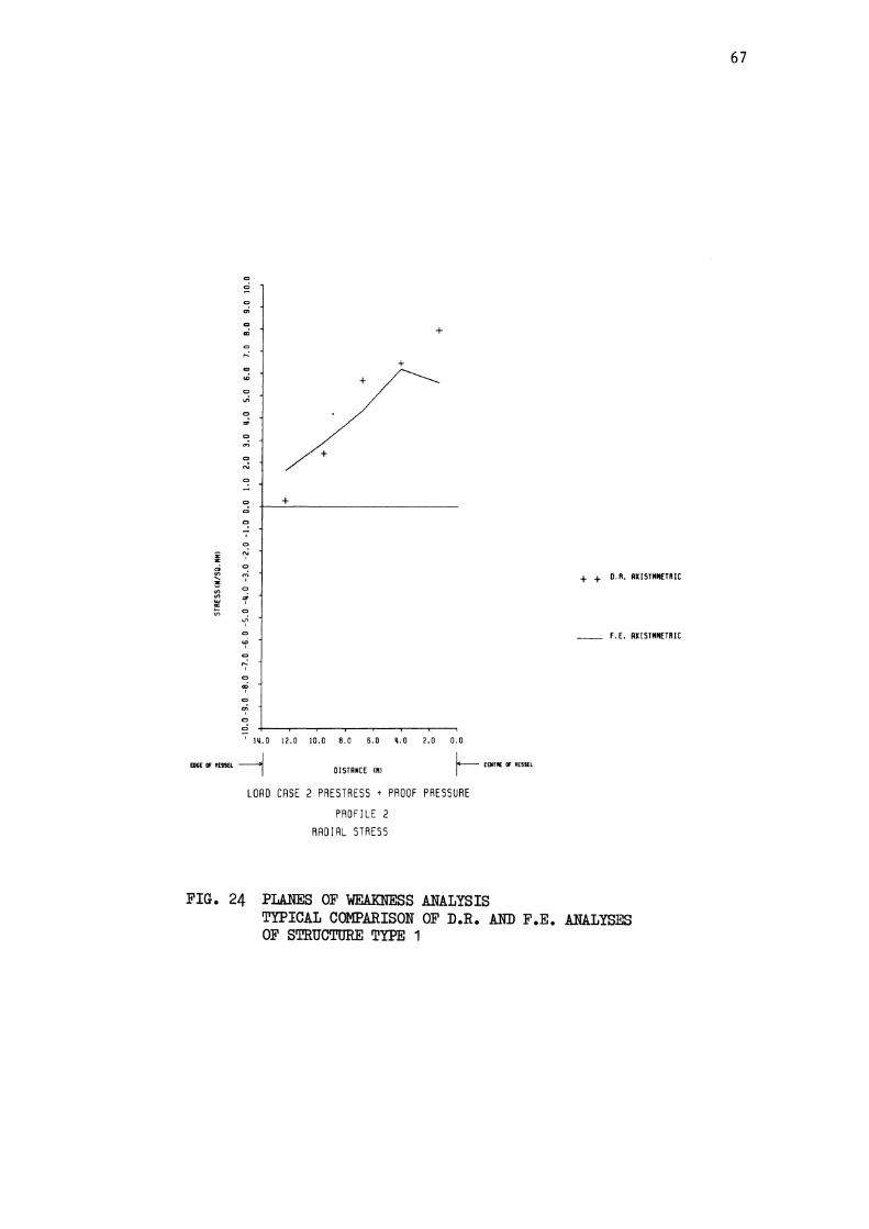
PROFILE 2 RADIAL STRESS
FIG. 24 PLANES OF WEAlOOlSS ANALYSIS
+ + D. R. AXISTMMETRIC
__ f.E. AXISTMMETRIC
TYPICAL COMPARISON OF D.R. AND F.E. ANALYSES OF STRUCTURE TYPE 1
67

64
Penetrat ions cast in amulusnot fully bonded to rest of structure
.... --- --- .... ,- ~ ..... ", " /' ,
// '" / ' / \\
I \
I ' I ' I \
I \
/ \ ! <p '---it--t- -'""""""ili-----\- "'---1,--I I \ I \ I \ I \ I
\ I " /1 " / " ///
................... ...,/
~--- ----~
Fig.18. GROUPED AND DEBONDED PENETRATIONS
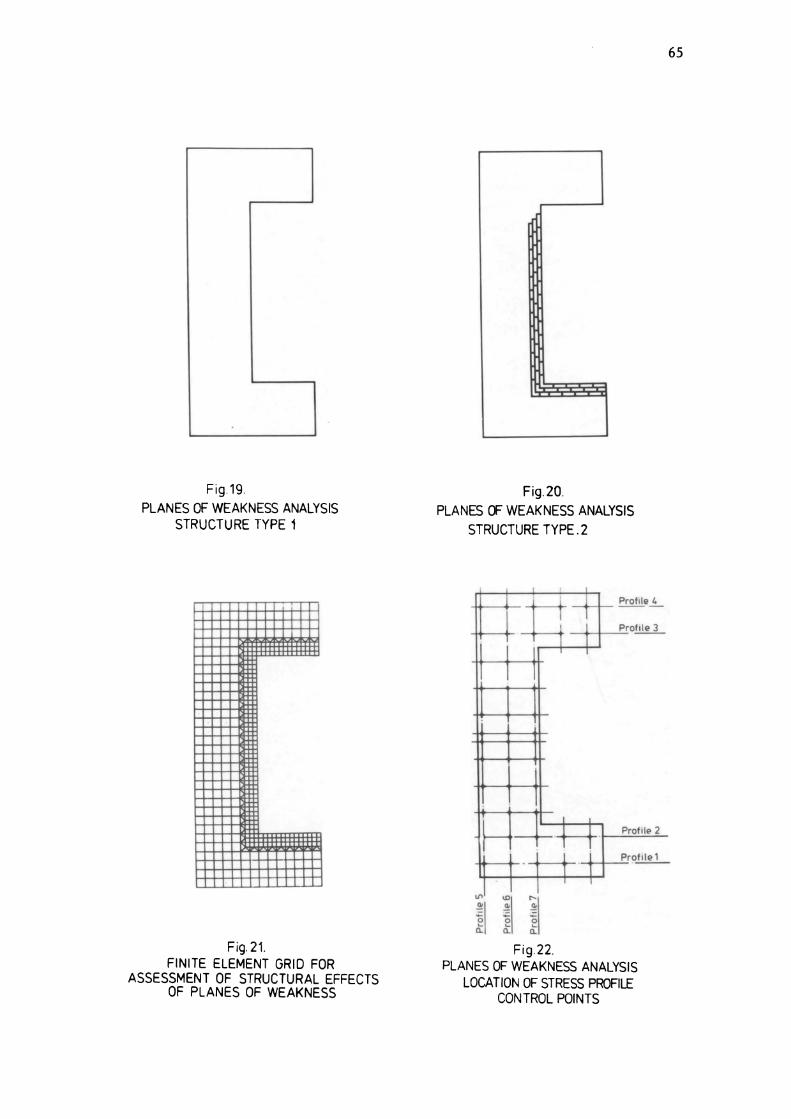
Fig.19. PLANES OF WEAKNESS ANALYSIS
STRUCTURE TYPE 1
Fig. 21. FINITE ELEMENT GRID FOR
ASSESSMENT OF STRUCTURAL EFFECTS OF PLANES OF WEAKNESS
Fig.20. PLANES OF WEAKNESS ANALYSIS
STRUCTURE TYPE. 2
.L 1 PrO"le~
1 ] Pro~
I 1 I T
I
I I
I
1 I
I ~
~l 1 Prot,le 2 ~ ~- T 1 1 1 Profile 1 , T
I I
il i\ j\ Fig.22.
PLANES OF WEAKNESS ANALYSIS LOCATION OF STRESS PROFILE
CON TROL POINTS
65

70
co
'" co
'" co ....
co ui
co ni
co
co co
o
'l' co .., , o ~ , o
"' , <:>
'" , o
~ <:>
'l' <>
'" , co .;
+ +
+ + STRUCTURE 1
__ STRUCTURE 2
'30.0 28.0 26.0 2Y.0 22.0 20.0 18.0 16.0 14.0 12.0 10.0 8.0 6.0 q.o 2.0 0.0
TOP " ""'El ---1
FIG. 27
DISTRNCE IMI
LOAD CASE 1 PRESTRESS ONLY
PROFILE 7 VERTICRL STRESS
PLANES OF WEAKNESS ANALYSIS TYPICAL COMPARISON OF STRESS PROFILES FOR STRUCTURES TYPE 1 AND 2
r-- IOn .. or ""El

o
'" o ... o r-
o <D
o .,; o =r
o N
o
, o N , o
~ o =r , o
'" , o <D , o r, o ... , o
'"
+ + + +
-t +-----
'30.0 2B.0 26.0 2~.0 22.0 20.0 IB.O 16.0 I~.O 12.0 10.0 B.O 6.0 ~.D 2.0
... """fL --1
FIG. 26
DISTRNCE IHI
LOAD CASE 1 PRESTRESS ONLY
PROFILE 6 VERTICRL STRESS
PLANES OF WEAKNESS ANALYSIS TYPICAL COMPARISON OF STRESS PROFILES FOR STRUCTURES TYPE 1 AND 2
69
+
+ + STRUCTURE 1
__ STRUCTURE 2
0.0
r-- IOn .. '" """

66
.. co
co .,; .. .; co .... .. .. '" on .. ,; .. .. <> nO .. .. cO .. i <>
~ .. ~ .. 'f
..
..; I ..
,.: I
C ... I ..
of .. ..
~ +
+ +
.. I~.O 12.0 10.0 8.0 6.0 ~.O 2.0 0.0
_ ......... --1 DISTANCE IMI r-- "'111£ at' "' ....
FIG. 23
LOAD CASE 2 PRESTRESS • PROOF PRESSURE
PROFILE II VERTICAL STRESS
PLANES OF WEA.KN]5S ANALYSIS
+ + D.R. AXISTMMETRIC
__ F.E. RXISYMMETRIC
TYPICAL COMPARISON OF D.R. AND F.E. ANALYSES OF STRUCTURE TYPE 1

~
'"
o
'"
o ~
o
'" o ... , o
1 o
'" , ~
~ , ~
'" , ~
~ o
~
+
+
+ + STRUCTURE I
-_ STRUCTURE 1
'I~.O 11.0 10.0 8.0 6.0 ~.O 1.0 0.0
IIIG, or '!>S'L --1
FIG. 28
o ISTRNCE IHI
LOAD CASE I PRESTRESS ONLY
PROFILE 2
RADIAL STRESS
~ co,,", IF """
PLANES OF WEAKN:HSS ANALYSIS TYPICAL COMPARISON OF STRESS PROFILES FOR STRUCTURES TYPE 1 AND 2
71
72
C>
c
'" CD
C>
'"
'" '" '" '"
<> <>
<>
, <>
~ C>
'"
<>
, <> ... ,
C>
C>
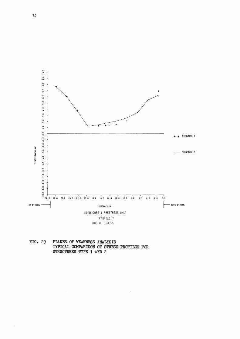
+
+ + STRUCTURE I
__ STRUCTURE 2
'30.0 28.0 26.0 2~.0 22.0 20.0 18.0 16.0 14.0 12.0 10.0 8.0 6.0 ~.O 2.0 0.0
TI' OF 'ES'" --1
FIG. 29
OISTRNCE IHI
LOAD CASE 1 PRESTRESS ONLY
PROFILE 7 RRDIRL STRESS
PLANES OF WEAKNESS ANALYSIS TYPICAL COMPARISON OF STRESS PROFILES FOR STRUCTURES TYPE 1 :AND 2
r--- IOn .. or mSEl

co co
co
'" co
co o co
, co
'" , co
'" , co
'f co
-? ., ~ co ~ , co
'" , ., '" , co o
+ + +
+ + STRUCTURE 1
__ STRUCTURE 2
7 Iq.o 12,0 10,0 B.O 6.0 q.o 2.0 0.0
fD"Of""" ~
FIG. 30
DISTRNCE IMI
LOAD CASE I PRESTRESS ONLY
PROFILE 2 HOOP STRESS
~"""Df""'l.
PLANm OF WEAKNESS ANALYSIS TYPICAL COMPARISON OF STRESS PROFILES FOR STRUCTURES TYPE 1 AND 2
73

74
co
2 co
'" co cD co ,..:
co .,;
co
'" co .,. co ~
co
'" .,
.,
., Q
., i ~ 0 ., '" .., ~
,
'" Q
'" ,.. w , -= <> '" -?
<>
~ co
~ ., ., <>
~ ., d ,
30.0
rIP IF """ --1
FIG. 31
+ + + + +
+
28.0 26.0 2~.0 22.0 20.0 18.0 16.0 lij.O 12.0 10.0 8.0 6.0 ~.O
DISTRNCE 1"1
LORD CRSE I PRESTRESS ONLY
PROFILE 7
HOOP STRESS
PLANES OF WEAKNESS ANALYSIS TYPICAL COMPARISON OF STRESS PROFILES FOR STRUCTURES TYPE 1 AND 2
+ + STRUCTURE I
-- STRUCTURE 2
2.0 0.0
~ .rl1llO OF """

'" '" '" m
.,
...
.,
.;
<>
"'
<>
"" <>
'"
., '" '" , '" '" ,
'" 1 ., ,. , ., "' , ., "' , ., , ., ... ., m
+ + +-------:+;::--...
'30.0 28.0 26.0 2ij.0 22.0 20.0 18.0 16.0 lij.O 12.0 10.0 8.0 6.0
IOI'Of""fL~
FIG. 32
OJ STRNCE IMI
LOAO CASE 2 PRESTRESS + PROOF PRESSURE
PROFILE 6
VERTICRL STRESS
PLANES OF WEAKNESS ANALYSIS TYPICAL COMPARISON OF STRESS PROFILES FOR STRUCTURES TYPE 1 AND 2
75
+ + STRUCTURE 1
-- STRUCTURE 2
2.0 0.0
r-- 10"l1li Of JUSlL

76
C>
.,;
C>
cO C>
cD
C>
,..:
C>
'" C>
"' '" '" '" '" C>
N
C>
'" C>
'" , '" N , '" '" '" '" , '" '1 '" <? '" ... , '" ~ '" cf " '"
+ + +
+ +
+ + STRUCTURE I
__ STRUCTURE 2
'30.0 28.0 26.0 2Q.O 22.0 20.0 18.0 16.0 IQ.O 12.0 10.0 8.0 6.0 Q.O 2.0 0.0
FIG. 33
DISTRNCE (HI
LOAO CASE 2 PRESTRESS • PROOF PRESSURE
PROFILE 7 VERTICAL STRESS
PLANES OF WEAKNESS ANALYSIS TYPICAL COMPARISON OF STRESS PROFILES FOR STRUCTURES TYPE 1 AND 2
r--- IOn .. or ,mEl

'" ...
'" on
'" '"
'" c '" ,
'" '" , o
=f o
<? o
of '" 'i '" ; '" .... o
+
C ---,.---,
'1'.0 12.0 10.0 B.O &.0 '.0 2.0 0.0
EDKorntsEL --I OISTANCE tN) r-- CO'IE ,., nSSEl
FIG. 34
LORD CRSE 2 PRESTRESS + PROOF PRESSURE
PROFILE 2 RADIAL STRESS
PLANES OF WEAKNESS ANALYSIS TYPICAL COMPARISON OF STRESS PROFILES FOR STRUCTURES TYPE 1 AND 2
77
+ + STIlUCTURE 1
-- STRUCTURE 2

78
<> eft
<>
'" <> .... <> ..;
<> .,;
<>
'"
<> nO
<> ci <> ,
<>
~ co
'" , <>
'" , <> ~ , <> .. , <> ,
<> ., <> m
+
'30.0 28.0 26.0 2~.0 22.0 20.0 IB.o 16.0 lij.O 12.0 10.0 8.0 6.0 ~.O 2.0 0.0
FIG. 35
DIsrANCf IMI
LOAD CASE 2 PRESTRESS + PROOF PRESSURE
PROFILE 7 RADIAL STRESS
PLANES OF ~S ANALYSIS TYPICAL COMPARISON OF STRE:)S PROFILES FOR STRUCTURE5 TYPE 1 AND 2
+ + STRUCrURE I
__ STRUCrURE 2

., ..
.,
...
., '" ., N
., o ., 7
'" N , ., ~ ., of ., u? ., <f ., ~ , ., m , ., '" , ., .,
+ +
-; lij.O 12.0 10.0 8.0 6.0 ij.O 2.0 0.0
EO" Of "'>EL --1 DISTANCE {M} ~ '''''' Of ""a
LOAD CASE 2 PRESTRESS + PROOF PRESSURE
PROFILE 2
HOOP STRESS
FIG. 36 PLANES OF WEAKNESS ANALYSIS
+ + STRUCTURE I
__ STRUCTURE 2
TYPICAL COMPARISON OF STRESS PROFILES FOR STRUCTURES TYPE 1 AND 2
79

80
c
~ .. '" c .; c .... .. <D .. .; .. ,;. .. '" .. .. .. .. c
, .. '" c
'" , .. ~ , .. "' , .. <D , C
.... , c
1 .. ~ .. o
+
+ + +
+ + STRUCTURE 1
__ STRUCTURE 2
'30.0 le.O 26.0 2~.0 21.0 20.0 le.o 16.0 I~.O 12.0 10.n e.o 6.0 ~.O 2.U 0.0
TIP '" "55EL --1
FIG. 37
·0 [STANCE IMI
LORD CRSE 2 PRESTRESS + PROOF PRESSURE
PROFILE 7
HOOP STRESS
PLANES OF WEAKNESS ANALYSIS TYPICAL COMPARISON OF STRESS PROFILES FOR STRUCTURES TYPE 1 AND 2
I-- "'TT'III OF ,mEL

81
Shuttered face
\ Planes of Weakness
Formers
Previous Pour Previous Pour
tinuous In-situ Ccn:rete '--'---
Fig.38. IN-SITU CONSTRUCTION FORMATION OF PLANES OF WEAKNESS WITHIN
A NORMAL SIZED POUR
82
Fig.39. OUTLINE PROPOSAL FOR GROUTED LINER

II' • .: 'II •
••
...•. · ~ ,'.'
I
.~.:: . ....
. " .. • III ' ~ • ~ .... ..
83
...---Grout
........--Main Liner
.'
.' ----Seal Welds L :.
.. '.
. . . .. ',., I' ...... :: • ..... / '::: ... :.::::::::'.:::'
. •.. p' .P"If""'I('~~~ . ' .".
"--------- Gas Duct or other penetration
.'
.' '.
-.. -: :, -: .
. ;. .... . .{;: ...... :-: .. ,' : .:~ ..
PCRV
Reactor Cavity
--Wall Concrete
Fig.40. PROPOSED DETAIL OF JUNCTION BETWEEN GROUTED MAIN LINER
AND GAS DUCT

84
Reactor Fuelling Mochine Cranei Beams '
Temporary Prestressed r-f:ooaete Cover
r--_ _ __ ~Shiek:led Flask / on Tracks
Precast Concre:..:..:te,----_____ I SupportWaU ~rE~~~~~~~31)
~ __ T,empa-ary Shielded Coller
~~. ' . ~~~ Gallery ~ IL..-__ ...J
Shield Wall " -.-Permanent built aft~ Shielded Door Reoc:tor "'-____ Temporary Defuelling 1 Platfam
2 FWmanent _____ ... 3 _ _ -:-:--_ --.-. _ ' _ _ standpipe Regioo Man Acx::.ess r---:-......:.:L..J......I.=::a::..~-.l..---.:::..." ---, ....
Gas Dome
Prestress:::,:i ~~ Gallery
Standpi~ Region
Shield W lis ./ built after Reactor De fuelling
/ /
-SECTION-
-PLAN-
/
"
I
//\ /
Liner
Aa;ess to and from AnteChamber
Fig 41 OUTLINE SCHEME FOR REMOVAL a= STANDPIPE REGION TO GIVE ACCESS FOR REMOVAL OF
REACTOR CORE AND INTERNALS

85
"W SUI STAnOtil
--------~ - -
Fig.42. SITE PLAN - TYPICAL PWR STATION

1. A
uxi
llia
ry
build
ing
. 0
0
0'
2. R
ea
cto
r bu
ildin
g.
3.
Con
trol
bu
ildin
g.
4.
Tur
bine
bui
ldin
g.
5.
Dei
sel
bui l
ding
.
4 I II
I ~) ~
6.
Fue
l bu
ildin
g.
7. R
adio
activ
e w
aste
st
ora
ge
& p
roce
ssin
g bu
ildin
g.
Fig
43
MA
JOR
S
TR
UC
TU
RE
S
OF
TY
PIC
AL
PW
.R.
ST
AT
ION

~
Per
sonn
el
acce
ss h
a tc
h
Cf. E
quip
men
t h
atc
h
..... ! ..........
_---,
/
I I
~A " 9!
~ ~
-+-:~TI.
\
I ,
----
-'-
' ..
r-
-I~~
RPV
.
PLA
N
~
R.B.
I
S~ri
n9 li~l_
~ R
.PV.
Inco
re
i nst
rum
eri
tatio
n
tun
ne
l
SE
CTI
ON
A
-A
Fig
.44
. R
EA
CT
OR
B
UIL
DIN
G
OU
TL
INE
OF
T
YP
ICA
L
PW
R
ST
AT
ION
0
0
........

Re
act
or
Sec
tion
A-A
Rea
ctor
Sec
tion
B-8
~-lLrLJ~Y ?
r= ~
Pla
n
1. -
Pri
ma
ry s
hiel
d w
all
2. -
Re
acto
r ca
vity
3.
-R
efue
lling
ca
vity
4.
-S
tea
m g
en
era
tor
com
pa
rtm
en
t (s
eco
nd
ary
sh
ield
wa
lls 1
5.
-R
ea
cto
r bu
ildin
g sh
ell
6. -
Pre
ssu
rise
r C
ompa
rtm
ent
Fig
45
R
EA
.CT
OR
B
UIL
DIN
G
ST
RU
CT
UR
ES
O
F
TY
PIC
AL
P
WR
S
TA
TIO
N
00
0
0

Steam generator
Reactor coolant pump
Reactor pressure Vessel
Fig.40. NUCLEAR STEAM SUPPLY SYSTEM OF TYPICAL PWR.
89

90
Upper support assembly ---
Hold down spring
Upper support __ column
R.C.C.A. guide --.j~~'
Core barrel----.::::~.J
bU~Ii=====t= = == ==== Upper core plate
Baffle plate --~
t Lower core pia te
Lower support __ __ column
Lower core support --~~~~W~~I-
Instrumentation -----~~UiI=R~ columns
Secondary support structure
Core region
Lower internal structure
Fig.47. SECTION THROUGH REACTOR PRESSURE VESSEL OF TYPICAL PWR

Seal ring cooling ducts ------"'"
I .•.... . ~.~~ ... '. . ..
Reactor cavity seal ring ----¥:....,.£..IQ.-.I I
I Gallery roof ---------t?L.HH---:--
Expansion joint ---~----1P'/m1=7.¥~==~C==::J:""'--J Reactor pressure vessel ---if'"
I Inner shield wall ------
I I S I gallery -----~---
~ REACTOR CAVITY
1--..1...-- +-+--{i7- NOZ Z LES ---4---;1.-
I S u pp 0 r t bo x cooli n9 d uc t ---+-'AFJ:JI!-4~-f!t.!.---f-
Insulati
Vessel
Ex -cor slots
..•. .. ;.
Main containment liner ----f-.... f+-~-....
& through-liner reinforcement connectors
I
I
Fig 48 SECTION THROUGH LOOP PIPE PENETRATION OF TYPICAL PWR PRESSURE VESSEL
91

92
, Cover plate ------------, , Reactor cavity seal ring ----------,
I Steam generator lower
restraint embedment -----1~~!:J~::=~~:d~::~~ Seol ring c~oling duct -----¥Cr-:
I Man access way ---------\''-;; Ex pansion joint , Reactor coolant pump -----f-,L tie rod e-mbedment
I 151 gallery,----------+<
I Closure welds ofter vessel----==F:;; insto 110 tion
I Reactor pressure vessel ---·-r.,1~
" . '. " . . ,. f ·
Insulation ....;.'---------+7iiI jj.,..H,.. ... ~-'- - - - - - --I
Reactor vessel lateral Jil~~~~V support 0
Ex-core detector
Ex- core detector Ist'ow'n
liner & through
liner reinforcement connectors - i1li:==::lll.----.J
Fig 49. SECTION THROUGH DETECTOR SLOT OF TYPICAL PWR PRESSURE VESSEL

lit;
a. b
, J
...
6.
" ..
~.6
RE
FUE
LLIN
G
CA
VIT
Y
~ 1
J S
team
ge
ne
rato
r A
"\ \.
• ,
vert
ica
l le
g re
stra
int
.. " ...
.. "~
" •
0 •
• /)
6
'0'
" .
.• p
•
RE
AC
TOR
I C
AV
ITY
':"/)" .
. . a
. /) •
. '·
·f
em
be
dm
en
ts
Su
pp
ort
bo
x co
olin
g
/' ......
... ~\---
-duct (
abov
e)
I ..
""
I,..A
'" •
..~ ,
,)
, ,.
~y ,,-=
,,\~
y~..
. ...
...<'
'' I
Rea
ctor
ves
sel
vert
ica
I \'
su
pp
ort
em
be
dm
en
ts
I 01
(a
bo
ve)
--------------+-------~lo~Jj_---------
+ -
.. ,
I<~~
-: :~.
\...:=
"'" -
" I
('
\ ,
I \ ~
I I ~
,/
.... ...
I'"
....
..... 1...
.. ....
....
.... ....
.... ....
,.~
/ ..... 1
" /'
.... I
",'
I I
;'.,
\ \
'::"~
":' ~
... \o
o
. ', ...
..
a' ..
-• .'
t-',
o " ...
.'.
-, liS\\~-'.
OOI'~
, ~
\.
\ \,~,,~
" J
" \...
.._
\/\
':. ;
: ..
...
o.
. ~ .. '
Fig.
SO
. P
LA
N S
HO
WIN
G
DE
TE
CT
OR
S
LO
TS
O
F
TY
PIC
AL
P
WR
P
RE
SS
UR
E
VE
SS
EL
----
Ex-c
ore
ne
utr
on
d
ete
cto
r sl
ots
\0
W

RE
FU
ELL
ING
CA
VIT
Y
Loop
pip
e p
en
etr
ati
on
s
Re
act
or
coo
lan
t pu
mp
tie
rod
em
bedm
ents
Re
act
or
vess
el
late
ral
sup
po
rt e
mb
ed
me
nts
Loca
l th
icke
ning
to
e
xte
rna
l g
eo
me
try
~. ,
""'I
: I
Ex-
core
neu
tron
d
ete
c to
r tu
be
s
,~Inner s
hiel
d w
all
., ....
; '''J~v£ "
I S
I G
alle
ry
Fig
.51
. P
LAN
O
N l
SI
GA
LL
ER
Y O
F T
YP
ICA
L
PW
R
PR
ES
SU
RE
VE
SS
EL
\0
..,...

RE
FU
ELL
ING
C
AV
ITY
Ste
am g
en
era
tor
low
er r
est
rain
t e
mb
ed
me
nts
coo
ling
Man
acc
ess
wa
y
---------+
----+
----liw
.1II
H-1
----
-T
"I
l I
I to
I S
I g
alle
ry &
a
cce
ss t
o e
x-co
re
neut
ron
de
tect
ors
"I'
.: ';
"I'
\&/0
' "
" ":
.~..:'
"",, /
II
II
II
'~4
'O,
'0,
I',
, ""
Q
Fig
.52
P
LAN
O
N
FU
ELL
ING
PO
OL
OF
TY
PIC
AL
P
WR
P
RE
SS
UR
E V
ES
SE
L
\.0
1
Il

96
Seal ring cooling ducts
I ..... . . ~.~~ ... '. . ..
Reactor cavity seal r ing ---¥...."L..ICl,.,.J I
I Goller y roof ---------+-:,.L+~---
Expansion joint ~-==~--t:~~~g~=,....r===~---J Reactor pressure vessel --......
I Inner shield wall ----~
I 151 gallery ---------
Vessel
Ex -co slots
I --+--- ~~--- +-+-~-NOZZLES-+-~-
~ REACTOR CAV ITY
DO x COO ling d u c t ---+-,<4Hw.-+I--JI---P."-!-----+-
Main containment liner ----4-..IN& through-liner reinforcement connectors
I
I
Fig.53. SECTION SHOWING POSSIBLE LOCATION OF WATER TANKS IN PWR PRIMARY SHIELD WALL
1 \
~ I J
S
team
ge
ne
rato
r "
( (Z
i
'"
vert
ica
l le
g re
stra
int
.' , •• "
6 .
,: ~
.. ,~
.,&
I
RE
FUE
LLIN
G
CA
VIT
Y
t_
" .. '
' ••
,/1 ..
.
t •
. ~ ,',.'
-"0
'1
("'".
I
. I
\...-""
" I
("'"
I .
I
~-/
I....
.;
...
, ..,
,'"
"..;
;",,
' I
... .,..
' /,,
" ;' ~"
"'r'"
I ,;'
I I
, . \
\ "
\ \
" , .. '
, I
" ' •• "
,b
•
• ',1
; .
,"
.. ~
' ,t
",
, , '
'., II
•
. .
·:'f
em
be
dm
en
ts
. S
up
po
rt
bo
x co
olin
g
, d
uct
(ab
ove)
,...<
.-I
Rea
ctor
ves
sel
vert
ica
I su
pp
ort
em
be
dm
en
ts
I 91
(a
bove
)
,---
Ex-c
ore
neu
tron
d
ete
cto
r sl
ots
Fig
54
PLA
N S
HO
WIN
G
PO
SS
IBLE
LO
CA
TIO
N
OF
WA
TER
T
AN
KS
IN
P
WR
P
RIM
AR
Y S
HIE
LD W
ALL
1.
0 '-
J
98
APPENDIX A
SUPPLEMENTARY INFORMATION
This appendix contains additional infonnation and discussion relating to a number of ideas mentioned but not fully described in the main report.
(a) Provision of preformed holes for the placement of explosive charges.
The use of explosives for the controlled demolition of concrete biological shields and pressure vessels is being investigated by !WC under Project 3 of the CEC programme on nuclear plant decommissioning. n"is work has shown that small explosive charges placed in holes formed at right angles to the inside face of a massive concrete structure can be used to strip off concrete layers from the face. Each concrete layer stripping operation is carried out using predetermined charge spacing and depth of burial designed to give optimum results with respect to safety, volume of material excava.ted and econ011lY. The layer by layer stripping operation is continued until the required thickness of concrete has been cratered off, or excavated. The indications are that a one metre thlckness could be fa.irly satisfactorily removed in a series of four layer stripping operations. If a mat of reinforcement is present close to the face of the concrete, the effect of the fit'st layer round of firings will be to blow the cover off and, depending on the reinforcement detail, break up some concrete behind the reinforcement. The reinforcement mat so exposed can be cropped or cut away to release any debris held behind it. Once the reinforcement mat has been removed the stripping process proceeds as normal.
No tests have been carried out to assess the effect of a liner bonded to the concrete by studs. It may be that, if the liner is cut through into discrete plates consistent with the expected pattern of explosive cratering, the concrete can be blown off in discrete pieces with the liner still attached to it. n"is would, however, have to be investigated by a programme of testine.
The layout of boreholes required to strip a given thickness, say one metre, of concrete could be predetermined at the design stage. This being so it would be possible to form holes in the concrete during construction of the vessel subject to the maintenance of adequate shielding. n"is would permit the placement of charges during decommissioning without having to bore or cut holes first. Boring or cutting such holes would produce a cert~ln amount of activated waste Which would have to be suitably disposed of. It would also be a time consuming process, increasing radiation doses received by decommissioning workers. A preferable approach would be to use shaped charges Which are faster and produce negligible active waste.
There are, however, two main problems with preformed holes:-
(1) Shine paths for radiation. (2) Integrity of the liner.

99
The concentration of holes will be such that shine paths for radiation could be a problem, forming 'hot spots' of activation outside of the designated activated zone. If unacceptable, this could be overcome if the holes were plugged with a material with good neutron Rhielding properties. Assuming that the concrete is cast up against the liner, the hole filler would have to be a solid object, such as graphite or lead, fixed in position before concrete placing, suitably debonded from the concrete. The size of the holes would be limited by the ability of the liner to span the hole, and whether the material in the hole could support the liner. In carrying out the ultimate load analysis for the Hartlepool/Heysham I vessels, crack width was limited to 32mm for this reason. It is not thought likely that the density of holes would cause major problems due to stress concentrations but this would have to be checked following design of a suitable layout of charges.
(b) Provision of preformed holes for the placement of a chemical demolition agent.
The use of a non-explosive chemical demolition agent to split up concrete overcomes problems due to noise, vibration, dust, flying debris, etc. associated with the use of explosives. If mixed with water and poured into cylindrical holes formed in the concrete, "BRISTAR" expands, generating eracks in the surrounding concrete. Thls product has been successfully used for breaking up rock and massive unreinforced concrete structures. For reinforced concrete, a close hole spacing of about 200mm to 300mm is requlred, hole diameters being 40mm to 5Omm. Provision of preformed holes subject to provisos mentioned in item (a) above ~ould aid the use of such an agent, but the number of holes would be such that stress concentrations could become quite significant.
(c) Provision of preformed cavities for the insertion of mechanical burster.
There are two types of hydraulic burster, namely wedge type and piston type, anrl both split the concrete by expanding outwards against the circumference of a suitable hole into which they have been placed. The spacing of holes, their posi tion, depth and angle govern the success of bursting. Generally speaking, the hole for the insertion of the burster should be less than 500mm from a free face. Alternatively, a number of bursters can be used simultaneously, in holes about 600mm apart in a line about 600mm from the free face. Hole diameter depends on the type of burster being used. Provided a free working face could first be established, hydraulic bursters could provide a controlled means of splitting up activated concrete for removal. The provision of preformed holes, subject again to the provisos mentioned in item (a) above would save the time consuning and expensive job of cutting or boring holes.

100
(d) Improvement in the neutron shielding properties of concrete to reduce the volume of activated concrete and surface dose rates.
Activation of the concrete in a PCRV is caused by production of radioactive isotopes due to capture of neutrons by the nucleii of certain elements present in the concrete. Before capture, fast neutrons must be slowed down to thermal levels. Hydrogen is very effective at slowing down neutrons over a wide range of energies. By increasing the amount of hydrogen in concrete, the neutron attenuating properties of the concrete can be improved and two methods of increasing the proportion of hydrogen in hardened concrete are:
(1) Increasing the amount of free and chemically bound water in the hardened cement paste.
(2) Using hydrous aggregates.
Method (1) could involve increasing the fineness of the cement and increasing the cement and water content of the mix combined with stringent curing procedures during construction. Migration of free water through concrete is very slow, even under PCRV operating temperatures. Naturally occurring aggregates with a high hydrogen content include limonite, geophite and serpentine.
The adoption of any of these measures would have to be preceded by trials to establish the effects on workability, heat of hydration during construction, creep and shrinkage properties and long term strength and durability of the resulting concrete.
Boron is very effective in capturing thermal neutrons and does not produce gamma-emitting isotopes. The addition of boron to concrete will reduce dose rates received by decommissioning workers from harmful gamma radiation. Some of the more readily available boron containing additives are soluble in water and have a deleterious effect on the concrete setting process. As a result, borated concretes used in practice in reactor construction in the U. S.A. and Japan have typically had boron contents of less than 1% by weight. However, Japanese researchers have succeeded in producing concrete mixes wi th a boron content of up to 6.4% using non-soluble boron frits. The presence of these appears to retard slightly the early gain of strength, but 28 day strengths similar to or even greater than comparable mixes without boron are achieved, and all of the trial mixes reported had 28 day strengths of greater than the 40 N/mm2 commonly specified for PCRVs. Incorporation of boron in the PCRV concrete may also affect reactor operating characteristics.
(e) Use of an alternative material to mild steel for the liner.
Discussions with liner design engineers have revealed that alternative materials to steel for liners have been investigated in the past. One of the important properties required by material used on heavy civil engineering construction sites is durability against damage from both normal site operations and misuse of equipment such as dropped scaffold tubes, reinforcing rods and the like. Recent tests on high density polyethylene sheet have shown that this material can be easily penetrated by dropped objects and, although easily repaired, the integrity of
101
the liner would depend on all such damage being identified before the liner is built in or covered up. Plastic materials used in industry for containment liners have good chemical resistance and elasticity properties but are not able to withstand the high temperatures normally found in a reactor. The long term effect of radiation on some plastics, with resulting embrittlement, is also a problem to be taken into account.
Stainless steet is used in nuclear installations as an impermeable containment membrane but this material is normally used where corrosive conditions prevail and Where ease of decontamination is required. Compared with mild steel, stainless steel is considerably more expensive and exhibits a higher level of harmful radioactive isotopes, such as nickel, when subjected to radiation. All enquiries to date have failed to identify a better material than mild steel for the liner.
Related Documents


![[Pause cafe] j.o sociaux](https://static.cupdf.com/doc/110x72/558c81f8d8b42acf268b46ac/pause-cafe-jo-sociaux.jpg)
