MUFFAKHAM JAH COLLEGE OF ENGINEERING AND TECHNOLOGY EC - 431 MICROWAVE ENGINEERING LAB (With effect from the academic year 2011-2012) STUDENT’S MANUAL DEPARTMENT OF ELECTRONICS AND COMMUNICATION ENGINEERING

Welcome message from author
This document is posted to help you gain knowledge. Please leave a comment to let me know what you think about it! Share it to your friends and learn new things together.
Transcript
MUFFAKHAM JAH
COLLEGE OF ENGINEERING AND TECHNOLOGY
EC - 431 MICROWAVE ENGINEERING LAB
(With effect from the academic year 2011-2012)
STUDENT’S MANUAL
DEPARTMENT OF
ELECTRONICS AND COMMUNICATION ENGINEERING

MICROWAVE LAB MANUAL ECE DEPARTMENT
Muffakham Jah College of Engineering and Technology Page ii
Vision and Mission of the Institution
Vision
To be part of universal human quest for development and progress by contributing high calibre,
ethical and socially responsible engineers who meet the global challenge of building modern
society in harmony with nature.
Mission
• To attain excellence in imparting technical education from the undergraduate through
doctorate levels by adopting coherent and judiciously coordinated curricular and co-curricular
programs
• To foster partnership with industry and government agencies through collaborative research
and consultancy
• To nurture and strengthen auxiliary soft skills for overall development and improved
employability in a multi-cultural work space
• To develop scientific temper and spirit of enquiry in order to harness the latent innovative
talents
• To develop constructive attitude in students towards the task of nation building and empower
them to become future leaders
• To nourish the entrepreneurial instincts of the students and hone their business acumen.
• To involve the students and the faculty in solving local community problems through
economical and sustainable solutions.
Vision and Mission of ECE Department
Vision
To be recognized as a premier education center providing state of art education and facilitating
research and innovation in the field of Electronics and Communication.
Mission
We are dedicated to providing high quality, holistic education in Electronics and Communication
Engineering that prepares the students for successful pursuit of higher education and challenging
careers in research, R& D and Academics.
Program Educational Objectives of B. E (ECE) Program:
1. Graduates will demonstrate technical competence in their chosen fields of employment by
identifying, formulating, analyzing and providing engineering solutions using current
techniques and tools
2. Graduates will communicate effectively as individuals or team members and demonstrate
leadership skills to be successful in the local and global cross-cultural working environment
3. Graduates will demonstrate lifelong learning through continuing education and professional
development
4. Graduates will be successful in providing viable and sustainable solutions within societal,
professional, environmental and ethical contexts
MICROWAVE LAB MANUAL ECE DEPARTMENT
Muffakham Jah College of Engineering and Technology Page iii
MUFFAKHAM JAH COLLEGE OF ENGINEERING AND TECHNOLOGY
BANJARA HILLS, ROAD NO-3, TELANGANA
LABORATORY MANUAL
FOR
MICROWAVE ENGINEERING LAB
Prepared by: IFTEKHARUDDIN Checked by:
Approved by:
MICROWAVE LAB MANUAL ECE DEPARTMENT
Muffakham Jah College of Engineering and Technology Page iv
MUFFAKHAM JAH COLLEGE OF ENGINEERING AND TECHNOLOGY
DEPARTMENT OF ELECTRONICS AND COMMUNICATIONS ENGINEERING
MICROWAVE ENGINEERING LAB
Code: EC431 Programme: UG
Branch: ECE Version No: 1
Year : IV Updated on: 04/04/2016
Semester :I No. of Pages: 67
Classification Status (Unrestricted/restricted): Unrestricted
Distribution List: Department, Lab, Library, Lab Incharge
Prepared by: 1) Name : 1) Name :
2) Sign : 2) Sign :
3)Designation : 3) Designation :
4) Date : 4) Date :
Verified by: 1) Name : * For Q.C Only
2) Sign : 1) Name :
3)Designation : 2) Sign :
4) Date : 3) Designation :
4) Date :
Approved by: (HOD) 1) Name:
2) Sign :
3) Date :
MICROWAVE LAB MANUAL ECE DEPARTMENT
Muffakham Jah College of Engineering and Technology Page v
EC 431
MICROWAVE ENGINEERING LAB
Instructions 3 Periods per week
Duration of University Examination 3 Hours
University Examination 50 Marks
Sessionals 25 Marks
List of Experiments:
1. Characteristics of Reflex Klystron oscillator, finding the mode numbers and efficiencies of
different modes. 2. Characteristics of Gunn diode oscillator, Power Output Vs Frequency, Power Output Vs
Bias Voltage. 3. Measurement of frequency and Guide wavelength calculation:
i. Verification of the relation between Guide wavelength, free space wavelength and cutoff
wavelength of X- band rectangular waveguide.
ii. Verification of the straight line relation between (1/lg)2 and (1/l0)
2 and finding the
dimension of the guide.
4. Measurement of low and high VSWRs: VSWR of different components like matched
terminals, capacitive and inductive windows, slide screw tuner for different heights of the
tuning posts etc.
5. Measurement of impedance.
6. To find parameters of Directional coupler.
7. To find Scattering matrices of Tees : E plane, H plane and Magic Tee.
8. To find Scattering matrices of Circulator.
9. Measurement of radiation patterns for basic microwave antennas like horn and parabolic
reflectors in E-plane and H-plane. Also to finding the gain, bandwidth and beam width these
antennas.
10. Study of various antennas like dipoles, loops, Yagi antenna, log periodic antenna and their
radiation pattern.
11. Mini Project
i. To design microwave components such as directional couplers, circulators and
hybrid junctions using simulation software tools.
ii. To design antennas arrays such as Binomial, Chebyshev using software tools.
MICROWAVE LAB MANUAL ECE DEPARTMENT
Muffakham Jah College of Engineering and Technology Page vi
MICROWAVE ENGINEERING LAB
GENERAL GUIDELINES AND SAFETY INSTRUCTIONS
1. Sign in the log register as soon as you enter the lab and strictly observe your lab timings.
2. Strictly follow the written and verbal instructions given by the teacher / Lab Instructor. If
you do not understand the instructions, the handouts and the procedures, ask the
instructor or teacher.
3. Never work alone! You should be accompanied by your laboratory partner and / or the
instructors / teaching assistants all the time.
4. It is mandatory to come to lab in a formal dress and wear your ID cards.
5. Do not wear loose-fitting clothing or jewellery in the lab. Rings and necklaces are usual
excellent conductors of electricity.
6. Mobile phones should be switched off in the lab. Keep bags in the bag rack.
7. Keep the labs clean at all times, no food and drinks allowed inside the lab.
8. Intentional misconduct will lead to expulsion from the lab.
9. Do not handle any equipment without reading the safety instructions. Read the handout
and procedures in the Lab Manual before starting the experiments.
10. Do your wiring, setup, and a careful circuit checkout before applying power. Do not
make circuit changes or perform any wiring when power is on.
11. Avoid contact with energized electrical circuits.
12. Do not insert connectors forcefully into the sockets.
13. NEVER try to experiment with the power from the wall plug.
14. Immediately report dangerous or exceptional conditions to the Lab instructor / teacher:
Equipment that is not working as expected, wires or connectors are broken, the
equipment that smells or “smokes”. If you are not sure what the problem is or what's
going on, switch off the Emergency shutdown.
15. Never use damaged instruments, wires or connectors. Hand over these parts to the Lab
instructor/Teacher.
16. Be sure of location of fire extinguishers and first aid kits in the laboratory.
17. After completion of Experiment, return the bread board, trainer kits, wires, CRO probes
and other components to lab staff. Do not take any item from the lab without permission.
18. Observation book and lab record should be carried to each lab. Readings of current lab
experiment are to be entered in Observation book and previous lab experiment should be
written in Lab record book. Both the books should be corrected by the faculty in each lab.
19. Handling of Semiconductor Components:Sensitive electronic circuits and electronic
components have to be handled with great care. The inappropriate handling of electronic
component can damage or destroy the devices. The devices can be destroyed by driving
to high currents through the device, by overheating the device, by mixing up the polarity,
or by electrostatic discharge (ESD). Therefore, always handle the electronic devices as
indicated by the handout, the specifications in the data sheet or other documentation.
20. Special Precautions during soldering practice
a. Hold the soldering iron away from your body. Don't point the iron towards you.
b. Don't use a spread solder on the board as it may cause short circuit.
c. Do not overheat the components as excess heat may damage the components/board.
d. In case of burn or injury seek first aid available in the lab or at the college dispensary
MICROWAVE LAB MANUAL ECE DEPARTMENT
Muffakham Jah College of Engineering and Technology Page vii
CONTENTS
Exp.No
Title of Experiment
Page.No
Study of Microwave Components 1
1 Characteristics of Reflex Klystron oscillator 16
2 Characteristics of Gunn diode oscillator 21
3 Measurement of frequency and Guide wavelength 25
4 Measurement of VSWR 29
5 Measurement of impedance. 33
6 Parameters of Directional coupler.
36
7 Scattering matrices of Tees : E plane, H plane and Magic Tee. 39
8 Scattering matrices of Circulator. 41
9 Radiation patterns for basic microwave antennas 43
10 Study of various microwave antennas 47
11 Mini Project
Design of Microwave components, Antenna arrays 51
12 Appendix 52
MICROWAVE LAB MANUAL ECE DEPARTMENT
Muffakham Jah College of Engineering and Technology Page 1
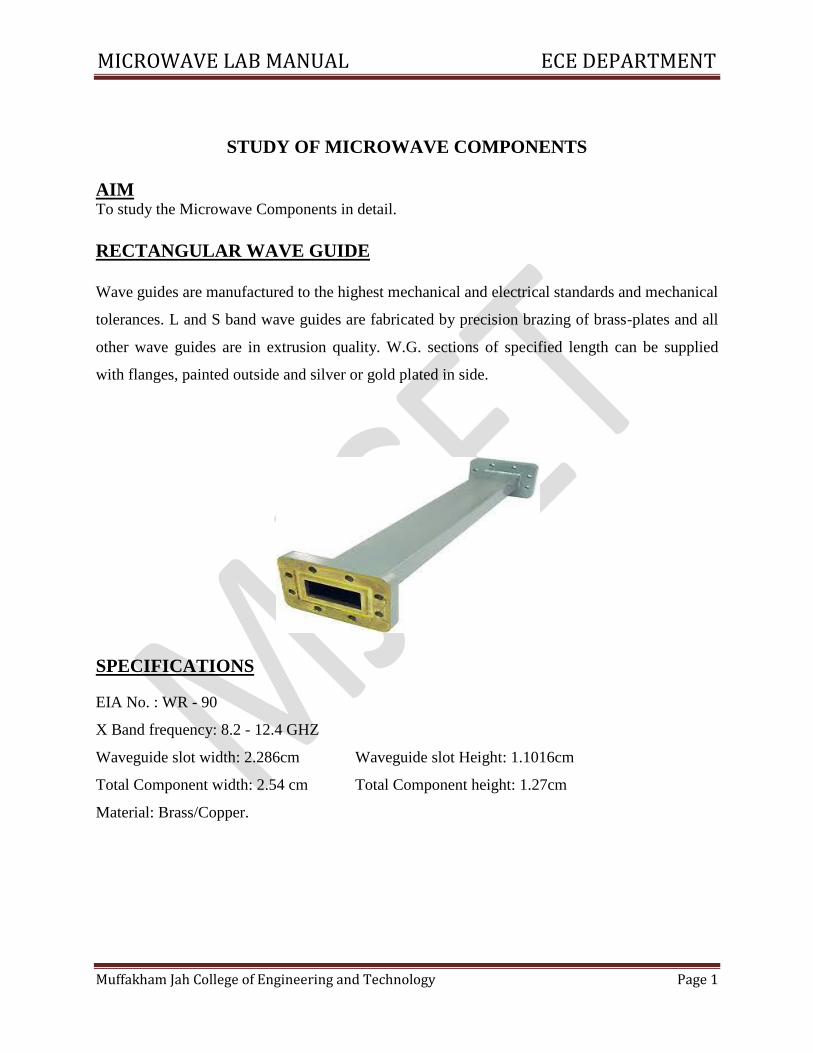
STUDY OF MICROWAVE COMPONENTS
AIM To study the Microwave Components in detail.
RECTANGULAR WAVE GUIDE
Wave guides are manufactured to the highest mechanical and electrical standards and mechanical
tolerances. L and S band wave guides are fabricated by precision brazing of brass-plates and all
other wave guides are in extrusion quality. W.G. sections of specified length can be supplied
with flanges, painted outside and silver or gold plated in side.
SPECIFICATIONS
EIA No. : WR - 90
X Band frequency: 8.2 - 12.4 GHZ
Waveguide slot width: 2.286cm Waveguide slot Height: 1.1016cm
Total Component width: 2.54 cm Total Component height: 1.27cm
Material: Brass/Copper.
MICROWAVE LAB MANUAL ECE DEPARTMENT
Muffakham Jah College of Engineering and Technology Page 2
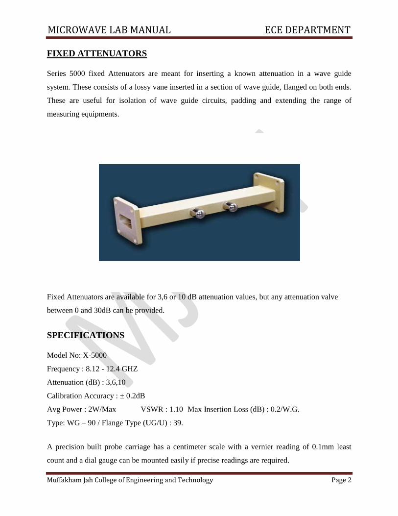
FIXED ATTENUATORS
Series 5000 fixed Attenuators are meant for inserting a known attenuation in a wave guide
system. These consists of a lossy vane inserted in a section of wave guide, flanged on both ends.
These are useful for isolation of wave guide circuits, padding and extending the range of
measuring equipments.
Fixed Attenuators are available for 3,6 or 10 dB attenuation values, but any attenuation valve
between 0 and 30dB can be provided.
SPECIFICATIONS
Model No: X-5000
Frequency : 8.12 - 12.4 GHZ
Attenuation (dB) : 3,6,10
Calibration Accuracy : ± 0.2dB
Avg Power : 2W/Max VSWR : 1.10 Max Insertion Loss (dB) : 0.2/W.G.
Type: WG – 90 / Flange Type (UG/U) : 39.
A precision built probe carriage has a centimeter scale with a vernier reading of 0.1mm least
count and a dial gauge can be mounted easily if precise readings are required.
MICROWAVE LAB MANUAL ECE DEPARTMENT
Muffakham Jah College of Engineering and Technology Page 3
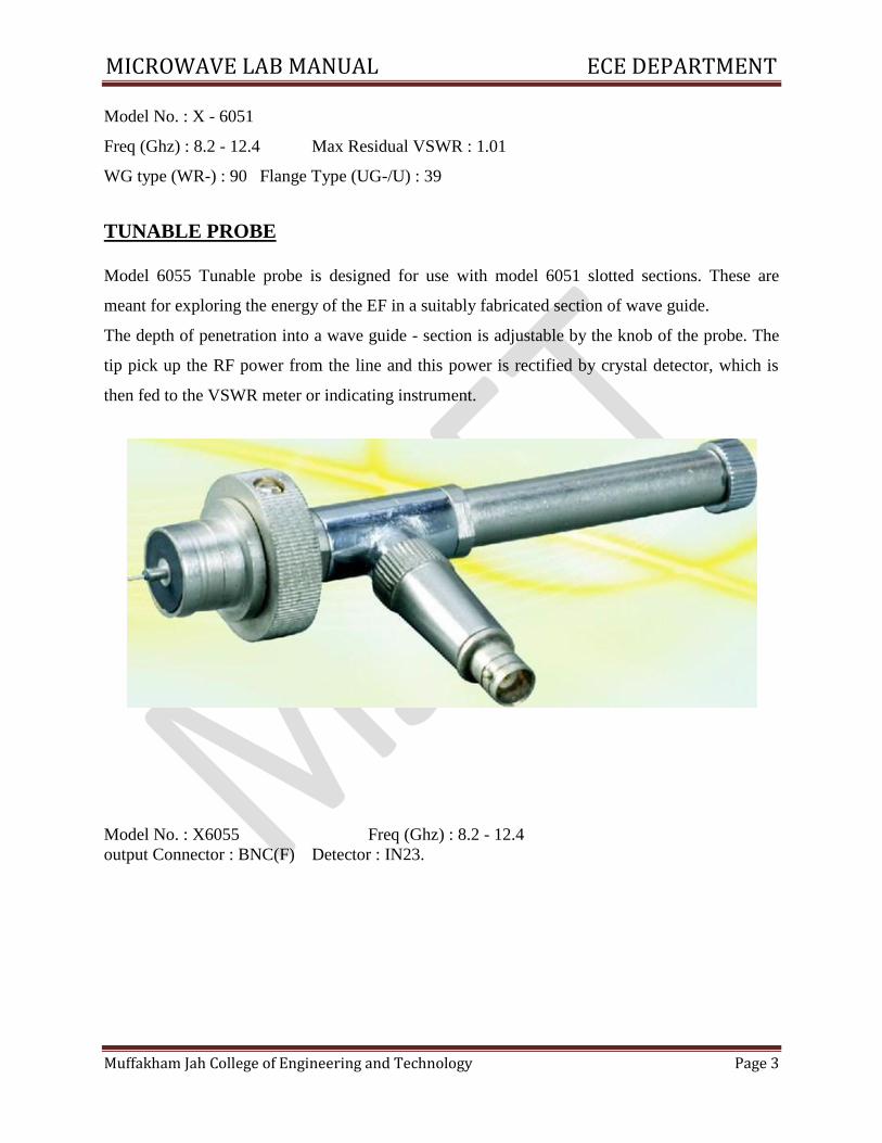
Model No. : X - 6051
Freq (Ghz) : 8.2 - 12.4 Max Residual VSWR : 1.01
WG type (WR-) : 90 Flange Type (UG-/U) : 39
TUNABLE PROBE
Model 6055 Tunable probe is designed for use with model 6051 slotted sections. These are
meant for exploring the energy of the EF in a suitably fabricated section of wave guide.
The depth of penetration into a wave guide - section is adjustable by the knob of the probe. The
tip pick up the RF power from the line and this power is rectified by crystal detector, which is
then fed to the VSWR meter or indicating instrument.
Model No. : X6055 Freq (Ghz) : 8.2 - 12.4
output Connector : BNC(F) Detector : IN23.
MICROWAVE LAB MANUAL ECE DEPARTMENT
Muffakham Jah College of Engineering and Technology Page 4
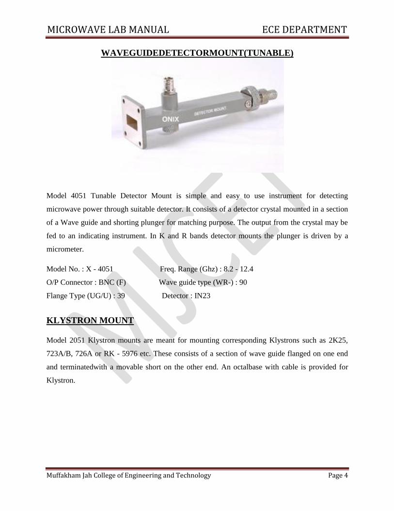
WAVEGUIDEDETECTORMOUNT(TUNABLE)
Model 4051 Tunable Detector Mount is simple and easy to use instrument for detecting
microwave power through suitable detector. It consists of a detector crystal mounted in a section
of a Wave guide and shorting plunger for matching purpose. The output from the crystal may be
fed to an indicating instrument. In K and R bands detector mounts the plunger is driven by a
micrometer.
Model No. : X - 4051 Freq. Range (Ghz) : 8.2 - 12.4
O/P Connector : BNC (F) Wave guide type (WR-) : 90
Flange Type (UG/U) : 39 Detector : IN23
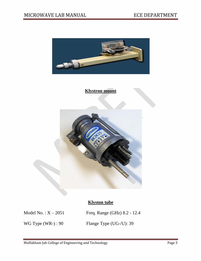
KLYSTRON MOUNT
Model 2051 Klystron mounts are meant for mounting corresponding Klystrons such as 2K25,
723A/B, 726A or RK - 5976 etc. These consists of a section of wave guide flanged on one end
and terminatedwith a movable short on the other end. An octalbase with cable is provided for
Klystron.
MICROWAVE LAB MANUAL ECE DEPARTMENT
Muffakham Jah College of Engineering and Technology Page 5
Klystron mount
Klyston tube
Model No. : X – 2051 Freq. Range (GHz) 8.2 - 12.4
WG Type (WR-) : 90 Flange Type (UG-/U): 39
MICROWAVE LAB MANUAL ECE DEPARTMENT
Muffakham Jah College of Engineering and Technology Page 6
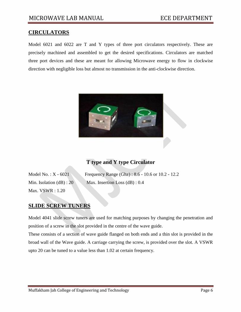
CIRCULATORS
Model 6021 and 6022 are T and Y types of three port circulators respectively. These are
precisely machined and assembled to get the desired specifications. Circulators are matched
three port devices and these are meant for allowing Microwave energy to flow in clockwise
direction with negligible loss but almost no transmission in the anti-clockwise direction.
T type and Y type Circulator
Model No. : X - 6021 Frequency Range (Ghz) : 8.6 - 10.6 or 10.2 - 12.2
Min. Isolation (dB) : 20 Max. Insertion Loss (dB) : 0.4
Max. VSWR : 1.20
SLIDE SCREW TUNERS
Model 4041 slide screw tuners are used for matching purposes by changing the penetration and
position of a screw in the slot provided in the centre of the wave guide.
These consists of a section of wave guide flanged on both ends and a thin slot is provided in the
broad wall of the Wave guide. A carriage carrying the screw, is provided over the slot. A VSWR
upto 20 can be tuned to a value less than 1.02 at certain frequency.
MICROWAVE LAB MANUAL ECE DEPARTMENT
Muffakham Jah College of Engineering and Technology Page 7
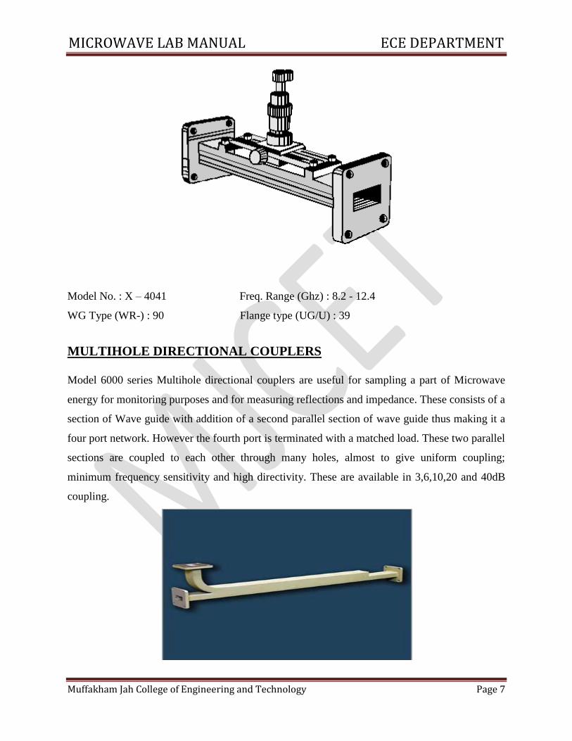
Model No. : X – 4041 Freq. Range (Ghz) : 8.2 - 12.4
WG Type (WR-) : 90 Flange type (UG/U) : 39
MULTIHOLE DIRECTIONAL COUPLERS
Model 6000 series Multihole directional couplers are useful for sampling a part of Microwave
energy for monitoring purposes and for measuring reflections and impedance. These consists of a
section of Wave guide with addition of a second parallel section of wave guide thus making it a
four port network. However the fourth port is terminated with a matched load. These two parallel
sections are coupled to each other through many holes, almost to give uniform coupling;
minimum frequency sensitivity and high directivity. These are available in 3,6,10,20 and 40dB
coupling.
MICROWAVE LAB MANUAL ECE DEPARTMENT
Muffakham Jah College of Engineering and Technology Page 8
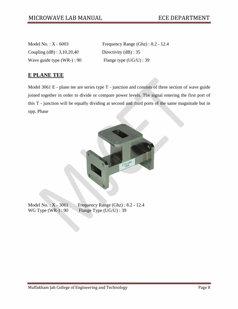
Model No. : X - 6003 Frequency Range (Ghz) : 8.2 - 12.4
Coupling (dB) : 3,10,20,40 Directivity (dB) : 35
Wave guide type (WR-) : 90 Flange type (UG/U) : 39
E PLANE TEE
Model 3061 E - plane tee are series type T - junction and consists of three section of wave guide
joined together in order to divide or compare power levels. The signal entering the first port of
this T - junction will be equally dividing at second and third ports of the same magnitude but in
opp. Phase
Model No. : X - 3061 Frequency Range (Ghz) : 8.2 - 12.4
WG Type (WR-) : 90 Flange Type (UG/U) : 39
MICROWAVE LAB MANUAL ECE DEPARTMENT
Muffakham Jah College of Engineering and Technology Page 9
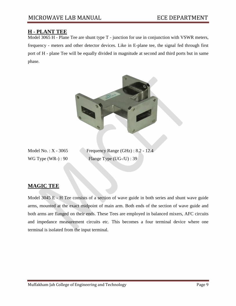
H - PLANT TEE Model 3065 H - Plane Tee are shunt type T - junction for use in conjunction with VSWR meters,
frequency - meters and other detector devices. Like in E-plane tee, the signal fed through first
port of H - plane Tee will be equally divided in magnitude at second and third ports but in same
phase.
Model No. : X - 3065 Frequency Range (GHz) : 8.2 - 12.4
WG Type (WR-) : 90 Flange Type (UG-/U) : 39
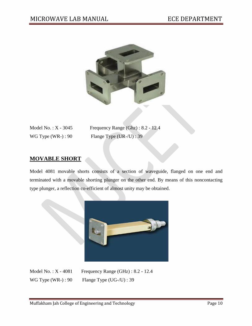
MAGIC TEE
Model 3045 E - H Tee consists of a section of wave guide in both series and shunt wave guide
arms, mounted at the exact midpoint of main arm. Both ends of the section of wave guide and
both arms are flanged on their ends. These Tees are employed in balanced mixers, AFC circuits
and impedance measurement circuits etc. This becomes a four terminal device where one
terminal is isolated from the input terminal.
MICROWAVE LAB MANUAL ECE DEPARTMENT
Muffakham Jah College of Engineering and Technology Page 10
Model No. : X - 3045 Frequency Range (Ghz) : 8.2 - 12.4
WG Type (WR-) : 90 Flange Type (UR-/U) : 39
MOVABLE SHORT
Model 4081 movable shorts consists of a section of waveguide, flanged on one end and
terminated with a movable shorting plunger on the other end. By means of this noncontacting
type plunger, a reflection co-efficient of almost unity may be obtained.
Model No. : X - 4081 Frequency Range (GHz) : 8.2 - 12.4
WG Type (WR-) : 90 Flange Type (UG-/U) : 39
MICROWAVE LAB MANUAL ECE DEPARTMENT
Muffakham Jah College of Engineering and Technology Page 11
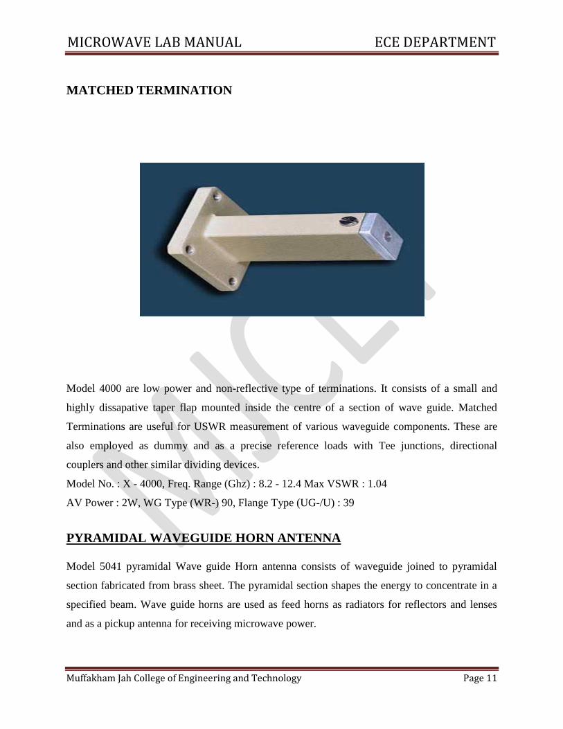
MATCHED TERMINATION
Model 4000 are low power and non-reflective type of terminations. It consists of a small and
highly dissapative taper flap mounted inside the centre of a section of wave guide. Matched
Terminations are useful for USWR measurement of various waveguide components. These are
also employed as dummy and as a precise reference loads with Tee junctions, directional
couplers and other similar dividing devices.
Model No. : X - 4000, Freq. Range (Ghz) : 8.2 - 12.4 Max VSWR : 1.04
AV Power : 2W, WG Type (WR-) 90, Flange Type (UG-/U) : 39
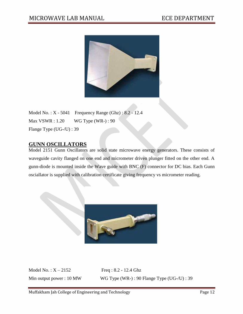
PYRAMIDAL WAVEGUIDE HORN ANTENNA
Model 5041 pyramidal Wave guide Horn antenna consists of waveguide joined to pyramidal
section fabricated from brass sheet. The pyramidal section shapes the energy to concentrate in a
specified beam. Wave guide horns are used as feed horns as radiators for reflectors and lenses
and as a pickup antenna for receiving microwave power.
MICROWAVE LAB MANUAL ECE DEPARTMENT
Muffakham Jah College of Engineering and Technology Page 12
Model No. : X - 5041 Frequency Range (Ghz) : 8.2 - 12.4
Max VSWR : 1.20 WG Type (WR-) : 90
Flange Type (UG-/U) : 39
GUNN OSCILLATORS Model 2151 Gunn Oscillators are solid state microwave energy generators. These consists of
waveguide cavity flanged on one end and micrometer driven plunger fitted on the other end. A
gunn-diode is mounted inside the Wave guide with BNC (F) connector for DC bias. Each Gunn
osciallator is supplied with calibration certificate giving frequency vs micrometer reading.
Model No. : X – 2152 Freq : 8.2 - 12.4 Ghz
Min output power : 10 MW WG Type (WR-) : 90 Flange Type (UG-/U) : 39
MICROWAVE LAB MANUAL ECE DEPARTMENT
Muffakham Jah College of Engineering and Technology Page 13
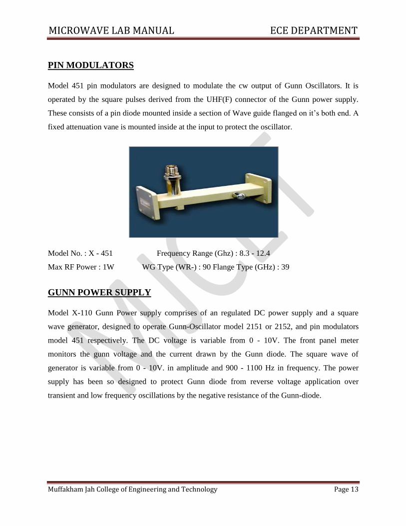
PIN MODULATORS
Model 451 pin modulators are designed to modulate the cw output of Gunn Oscillators. It is
operated by the square pulses derived from the UHF(F) connector of the Gunn power supply.
These consists of a pin diode mounted inside a section of Wave guide flanged on it’s both end. A
fixed attenuation vane is mounted inside at the input to protect the oscillator.
Model No. : X - 451 Frequency Range (Ghz) : 8.3 - 12.4
Max RF Power : 1W WG Type (WR-) : 90 Flange Type (GHz) : 39
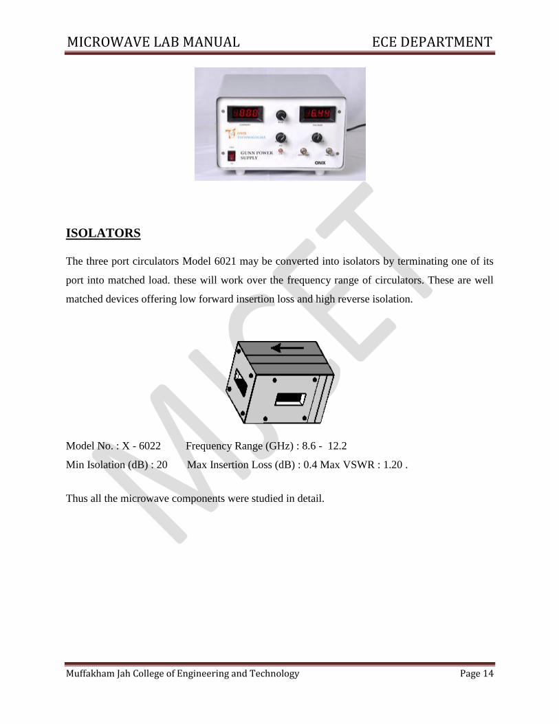
GUNN POWER SUPPLY
Model X-110 Gunn Power supply comprises of an regulated DC power supply and a square
wave generator, designed to operate Gunn-Oscillator model 2151 or 2152, and pin modulators
model 451 respectively. The DC voltage is variable from 0 - 10V. The front panel meter
monitors the gunn voltage and the current drawn by the Gunn diode. The square wave of
generator is variable from 0 - 10V. in amplitude and 900 - 1100 Hz in frequency. The power
supply has been so designed to protect Gunn diode from reverse voltage application over
transient and low frequency oscillations by the negative resistance of the Gunn-diode.
MICROWAVE LAB MANUAL ECE DEPARTMENT
Muffakham Jah College of Engineering and Technology Page 14
Gain control : ‘Coarse’
ISOLATORS
The three port circulators Model 6021 may be converted into isolators by terminating one of its
port into matched load. these will work over the frequency range of circulators. These are well
matched devices offering low forward insertion loss and high reverse isolation.
Model No. : X - 6022 Frequency Range (GHz) : 8.6 - 12.2
Min Isolation (dB) : 20 Max Insertion Loss (dB) : 0.4 Max VSWR : 1.20 .
Thus all the microwave components were studied in detail.
MICROWAVE LAB MANUAL ECE DEPARTMENT
Muffakham Jah College of Engineering and Technology Page 15
REVIEW QUESTIONS 1. What is microwave?
2. Mention the frequency band for a millimeter wave.
3. List some of IEEE microwave frequency bands.
4. List some of characteristic feature of microwave.
5. List some of the application of microwave technology.
6. Draw a simple microwave system.
7. What are waveguide `Tees’?
8. List the basic type of waveguide tees.
9. What is an isolator?
10. What is a circulator?
11. What is a directional coupler?
12. What is velocity modulation?
13. Mention the Principle used in Klystron?
14. When the o/p power of reflex klystron maximum?
15. What is meant by attenuator?
MICROWAVE LAB MANUAL ECE DEPARTMENT
Muffakham Jah College of Engineering and Technology Page 16
1. CHARACTERISTICS OF REFLEX KLYSTRON OSCILLATOR
AIM
To study the Characteristics of Reflex Klystron Oscillator, find mode numbers and efficiencies
of different modes.
APPARATUS REQUIRED:
Klystron Power Supply, Klystron with mount, Isolator, Frequency meter, Variable Attenuator,
Slotted section with Probe carriage, CRO, Movable Short.
THEORY
Klystron is a microwave vacuum tube employing velocity modulation. These electrons move
towards the repeller (ie) the electrons leaving the cavity during the positive half cycle are
accelerated while those during negative half cycle are decelerated. The faster ones penetrate
further while slower ones penetrate lesser in the field of repeller voltage. But, faster electrons
leaving the cavity take longer time to return and hence catch up with slower ones. In the cavity
the electrons bunch and intract with the voltage between the cavity grids. It consists of an
electron gun producing a collimated electron beam. It bunches pass through grids at time the grid
potentials is such that electrons are decelerated they give by energy. The electrons are then
collected by positive cavity wall near cathode. To protect repeller from damage, repeller voltage
is applied before accelerating voltage.
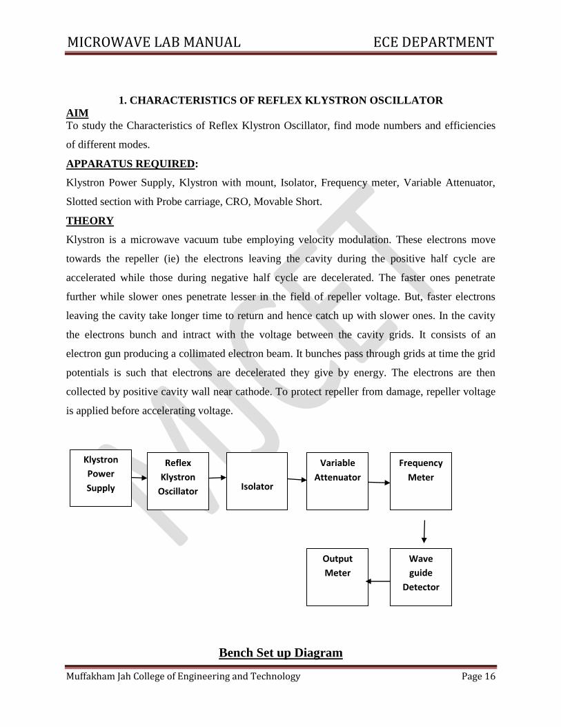
Bench Set up Diagram
Klystron
Power
Supply
Reflex
Klystron
Oscillator
Output
Meter
Wave
guide
Detector
Frequency
Meter
Variable
Attenuator
Isolator
MICROWAVE LAB MANUAL ECE DEPARTMENT
Muffakham Jah College of Engineering and Technology Page 17
PROCEDURE
1) Assemble the components as shown in fig.
2) After following the necessary precautions, the Klystron Power Supply is switched ON.
3) To obtain peak voltage, the attenuator is positioned at it’s minimum attenuation.
4) Vary the repeller voltage from it’s maximum negative value and increase it in steps on N and
record output power and frequency.
5) The frequency is measured by tuning the basic frequency meter to have a dip in the output
voltage each time.
6) The frequency meter is detuned before measuring the output power each time.
7) The mode characteristics of Reflex Klystron is plotted. (i.e. Output Voltage Vs Repeller
voltage and Frequency Vs Repeller voltage)
BASIC PRECAUTIONS
1) During operation of Klystron, repeller does not carry any current and as such it may severely
be damaged by electron bombardment. To protect repeller from such damage, the repeller
negative voltage is always applied before anode voltage.
2). Therepeller voltage should be varied in one direction to avoid hysteres is in klystrons
3) The heater voltage should be applied first and cooling should be provided simultaneously after
some time other voltages should be applied taking precaution
4) While measuring power, the frequency meter should be detained each time because there is a
dip in the output power when the frequency is tuned.
5) To avoid loading of the klystron an isolator/attenuation should invariably be used between
klystron and the rest of the set-up.
MICROWAVE LAB MANUAL ECE DEPARTMENT
Muffakham Jah College of Engineering and Technology Page 18
CALCULATIONS
(i) Knowing mode top voltages of two adjacent modes, mode numbers of the modes is
computed from the equation,
N2/ N1= V2/ V1= (n+1)+3/4/n+3/4
where V1 and V2 are the values of repeller voltages required to operate the klystron in mode
numbers N1 and N2.
(ii) Knowing mode number, transit time of each mode is calculated from
t 1 =(n+3/4)/f01= N1/f01
f01 → frequency of microwave operation in one mode.
(iii) ETR – Electronic tuning range i.e, the frequency band from one end of the mode to another
is calculated by
ETR = f1max – f1min for N1 mode (GHz)
f1max – f1min → half power frequencies
(iv) ETS – Electronic tuning sensitivity
ETS = = f1max – f1min/V1max- V1min (MHz/V)
f1max, f1min → half power frequency
V1max, V1min→ corresponding repeller voltages for a particular mode.
MICROWAVE LAB MANUAL ECE DEPARTMENT
Muffakham Jah College of Engineering and Technology Page 19
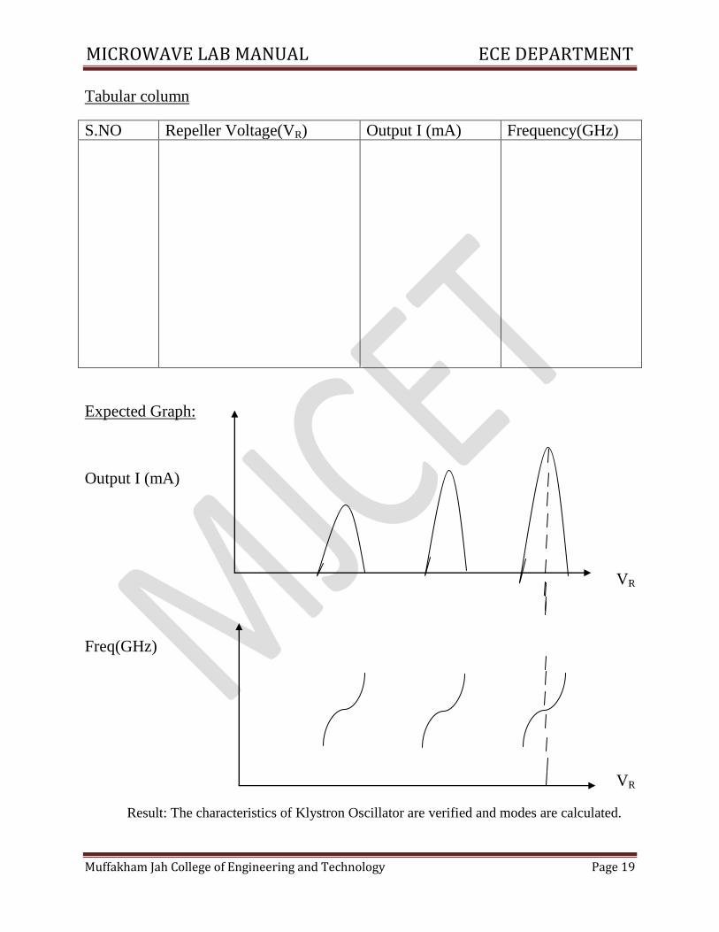
Tabular column
S.NO Repeller Voltage(VR) Output I (mA) Frequency(GHz)
Expected Graph:
Output I (mA)
VR
Freq(GHz)
VR
Result: The characteristics of Klystron Oscillator are verified and modes are calculated.
MICROWAVE LAB MANUAL ECE DEPARTMENT
Muffakham Jah College of Engineering and Technology Page 20
REVIEW QUESTIONS
1. List two basic configurations of Klystron tubes.
2. What is velocity modulation?
3. List the characteristic of two cavity klystron amplifier.
4. Write a note on mode of oscillations.
5. Draw the reflex klystron modes.
6. Higher order mode occurs at ____________ repeller voltage.
7. When the o/p power of reflex klystron maximum?
8. List the application of reflex klystron.
9. What is transit time?
10. Which mode number is most frequently used? Why?
MICROWAVE LAB MANUAL ECE DEPARTMENT
Muffakham Jah College of Engineering and Technology Page 21
2. CHARACTERISTICS OF GUNN DIODE OSCILLATOR
AIM: Study of VI characteristics of Gunn diode Oscillator.
APPARATUS:
X-Band Gunn Oscillator, Microwave bench, PIN modulator, Isolator,
Frequency meter, Variable attenuator, Slotted section, Tunable probe, Detector
Mount, Matched termination, Gunn power supply, Wave guide stand, BNC cable,
Cooling fan.
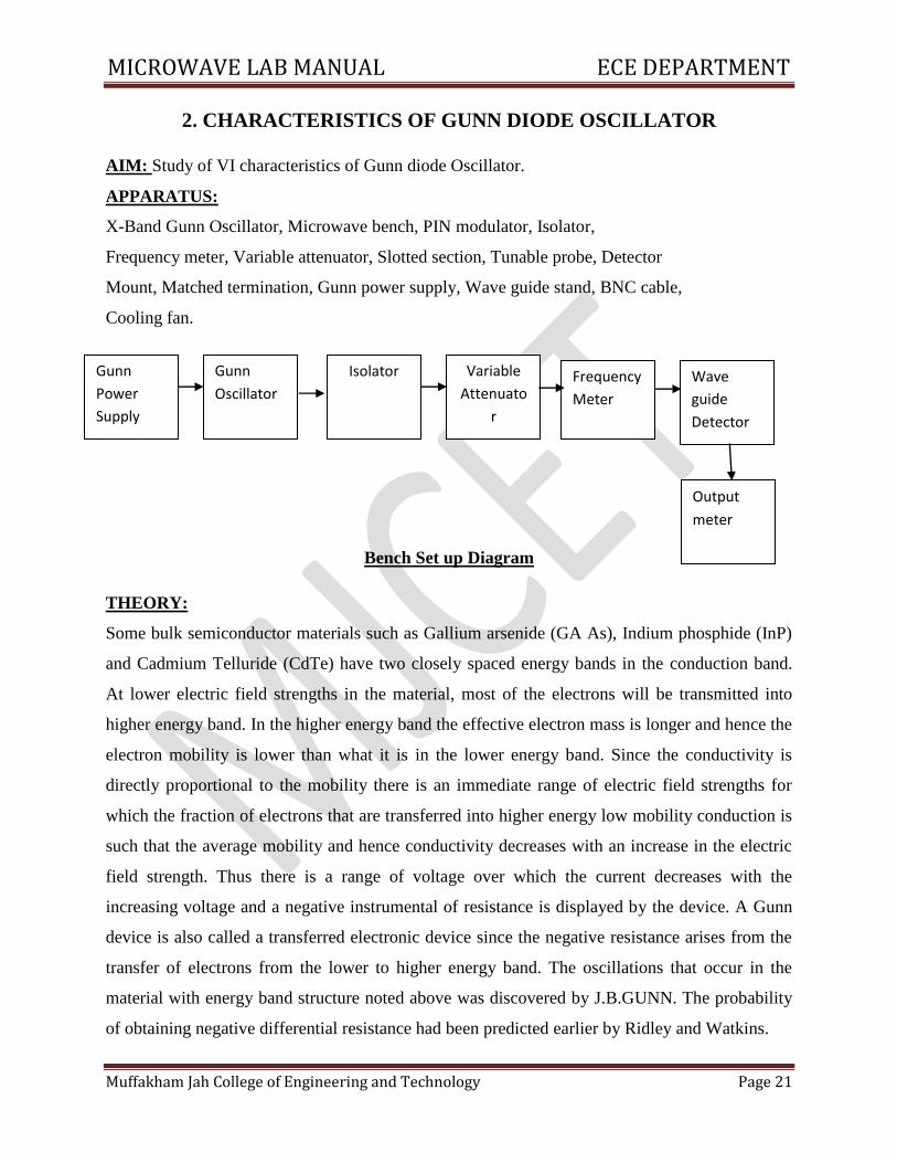
Bench Set up Diagram
THEORY:
Some bulk semiconductor materials such as Gallium arsenide (GA As), Indium phosphide (InP)
and Cadmium Telluride (CdTe) have two closely spaced energy bands in the conduction band.
At lower electric field strengths in the material, most of the electrons will be transmitted into
higher energy band. In the higher energy band the effective electron mass is longer and hence the
electron mobility is lower than what it is in the lower energy band. Since the conductivity is
directly proportional to the mobility there is an immediate range of electric field strengths for
which the fraction of electrons that are transferred into higher energy low mobility conduction is
such that the average mobility and hence conductivity decreases with an increase in the electric
field strength. Thus there is a range of voltage over which the current decreases with the
increasing voltage and a negative instrumental of resistance is displayed by the device. A Gunn
device is also called a transferred electronic device since the negative resistance arises from the
transfer of electrons from the lower to higher energy band. The oscillations that occur in the
material with energy band structure noted above was discovered by J.B.GUNN. The probability
of obtaining negative differential resistance had been predicted earlier by Ridley and Watkins.
Gunn
Power
Supply
Gunn
Oscillator
Isolator Variable
Attenuato
r
Frequency
Meter
Output
meter
Wave
guide
Detector
MICROWAVE LAB MANUAL ECE DEPARTMENT
Muffakham Jah College of Engineering and Technology Page 22
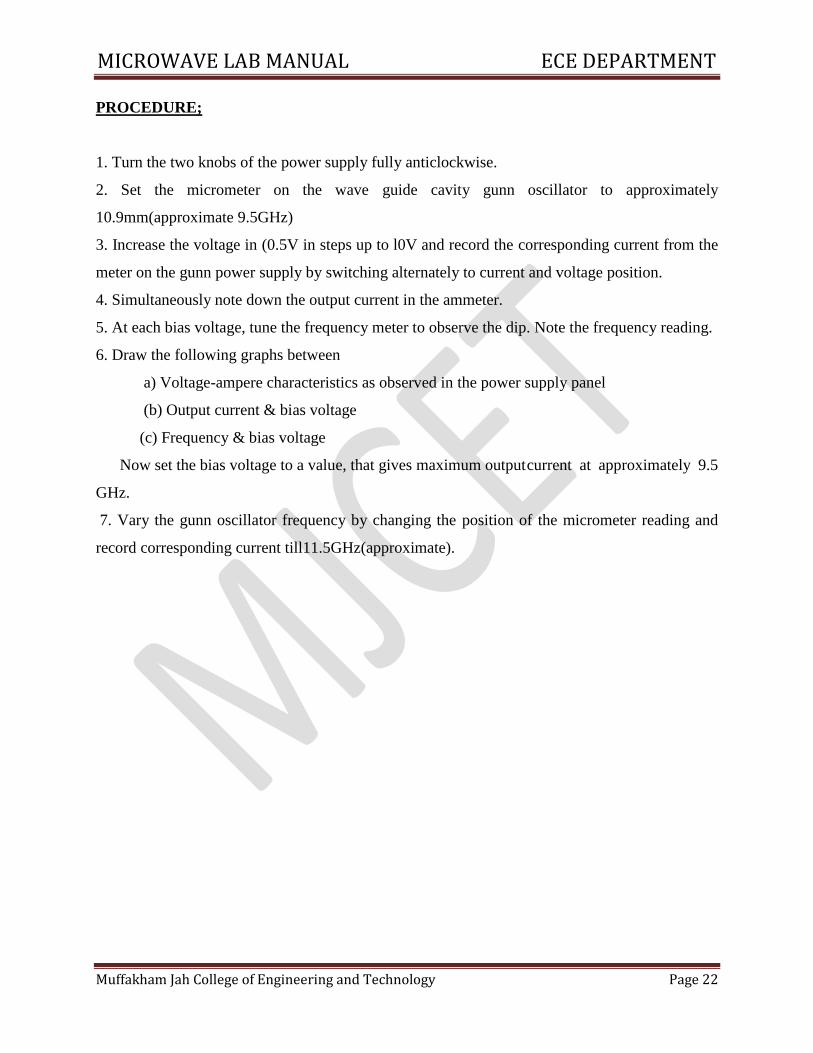
PROCEDURE;
1. Turn the two knobs of the power supply fully anticlockwise.
2. Set the micrometer on the wave guide cavity gunn oscillator to approximately
10.9mm(approximate 9.5GHz)
3. Increase the voltage in (0.5V in steps up to l0V and record the corresponding current from the
meter on the gunn power supply by switching alternately to current and voltage position.
4. Simultaneously note down the output current in the ammeter.
5. At each bias voltage, tune the frequency meter to observe the dip. Note the frequency reading.
6. Draw the following graphs between
a) Voltage-ampere characteristics as observed in the power supply panel
(b) Output current & bias voltage
(c) Frequency & bias voltage
Now set the bias voltage to a value, that gives maximum output current at approximately 9.5
GHz.
7. Vary the gunn oscillator frequency by changing the position of the micrometer reading and
record corresponding current till11.5GHz(approximate).
MICROWAVE LAB MANUAL ECE DEPARTMENT
Muffakham Jah College of Engineering and Technology Page 23
Tabular column:
S.No Gunn
Voltage
V(Volts)
Gunn
Current I
(mA)
Output Current IO (mA) Output Frequency
(GHz)
MICROWAVE LAB MANUAL ECE DEPARTMENT
Muffakham Jah College of Engineering and Technology Page 24
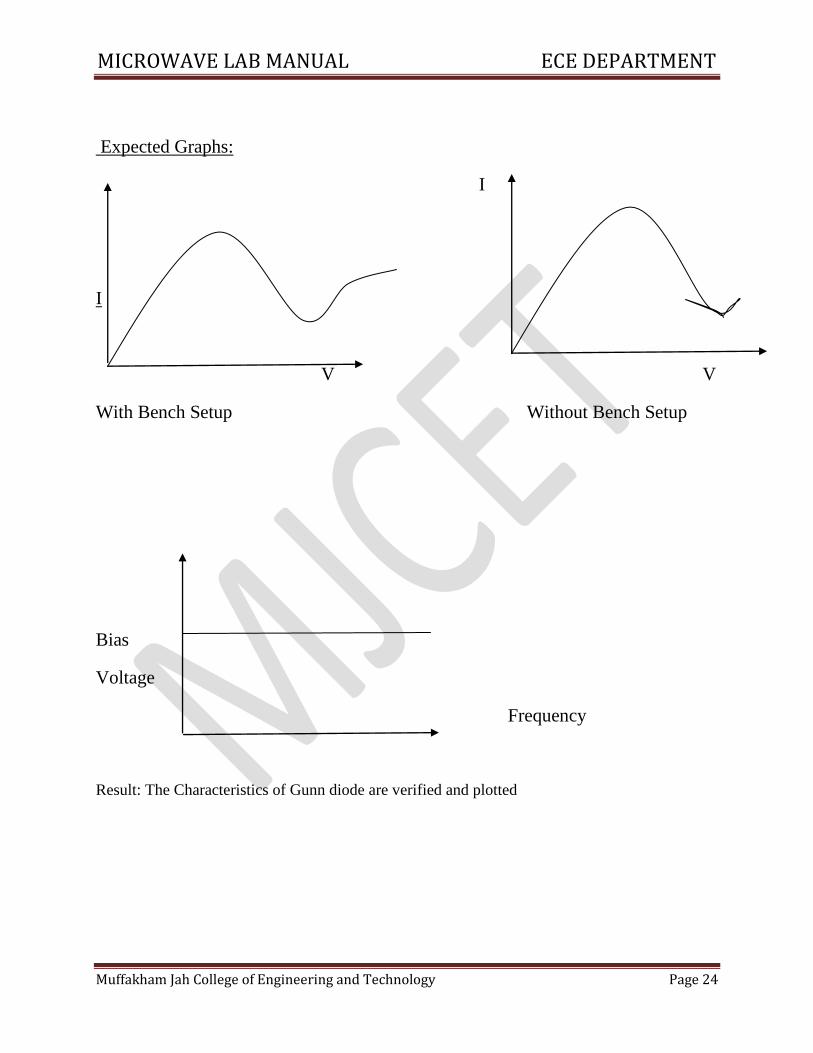
Expected Graphs:
I
I
V V
With Bench Setup Without Bench Setup
Bias
Voltage
Frequency
Result: The Characteristics of Gunn diode are verified and plotted
MICROWAVE LAB MANUAL ECE DEPARTMENT
Muffakham Jah College of Engineering and Technology Page 25
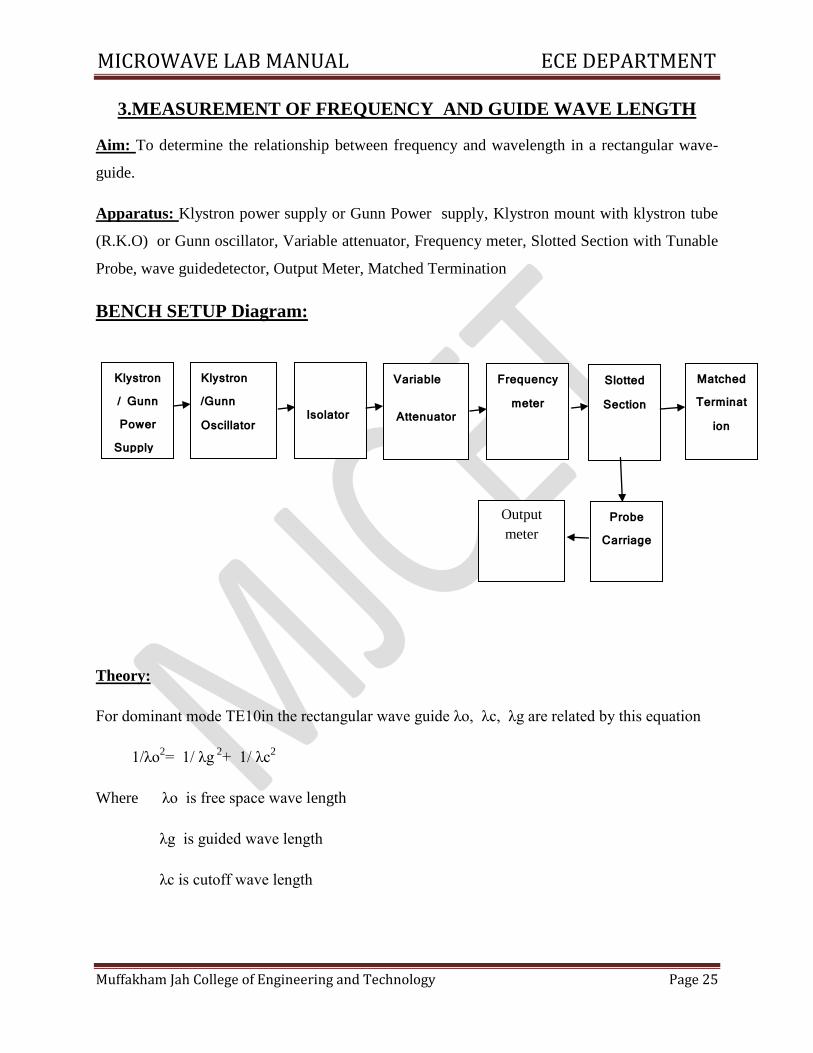
3.MEASUREMENT OF FREQUENCY AND GUIDE WAVE LENGTH
Aim: To determine the relationship between frequency and wavelength in a rectangular wave-
guide.
Apparatus: Klystron power supply or Gunn Power supply, Klystron mount with klystron tube
(R.K.O) or Gunn oscillator, Variable attenuator, Frequency meter, Slotted Section with Tunable
Probe, wave guidedetector, Output Meter, Matched Termination
BENCH SETUP Diagram:
Theory:
For dominant mode TE10in the rectangular wave guide λo, λc, λg are related by this equation
1/λo2= 1/ λg
2+ 1/ λc
2
Where λo is free space wave length
λg is guided wave length
λc is cutoff wave length
Klystron / Gunn Power Supply
Power / Gunn
Power
Supply
Klystron /Gunn Oscillator
Isolator
Isolator
Variable
Attenuator
Output
meter
Probe Carriage
Slotted
Section
Matched Terminat
ion
Frequency meter
Slotted Section
MICROWAVE LAB MANUAL ECE DEPARTMENT
Muffakham Jah College of Engineering and Technology Page 26
PROCEDURE:
1. Set up the equipment as shown in the figure
2. Set the variable attenuator at minimum.
3. Adjust the probe depth of the standing wave detector till a deflection is observed on the
V.S.W.R.
4. Keep the range dB of the V.S.W.R. meter in the 40dB position.
5. Energize the klystron. Use the mode at about -160V reflector voltage module with 1khz square
wave..
6. Adjust the reflector voltage to get maximum deflection on the V.S.W.R. meter.
FREQUENCY MEASUREMENT WITH THE FREQUENCY METER
1. Tune the frequency meter until a dip observed in the V.S.W.R. meter deflection. Tune the
frequency meter to obtain minimum deflection.
2. Note the frequency meter setting.
WAVE LENGTH MEASUREMENT:
1. Replace the termination with the variable short. Detune the frequency meter.
2. Move the probe along the line and watch the V.S.W.R. meter, the deflection will vary
strongly.
3. Move the probe to a minimum deflection point. To get an accurate reading, it is necessary
to increase the V.S.W.R. meter gain when close to a minimum.
4. Note and record the probe position.
5. Measure the wave-guide inner dimension. a = (22.860+0.046mm)or 2.29cm.
6. Calculate the frequency.
MICROWAVE LAB MANUAL ECE DEPARTMENT
Muffakham Jah College of Engineering and Technology Page 27
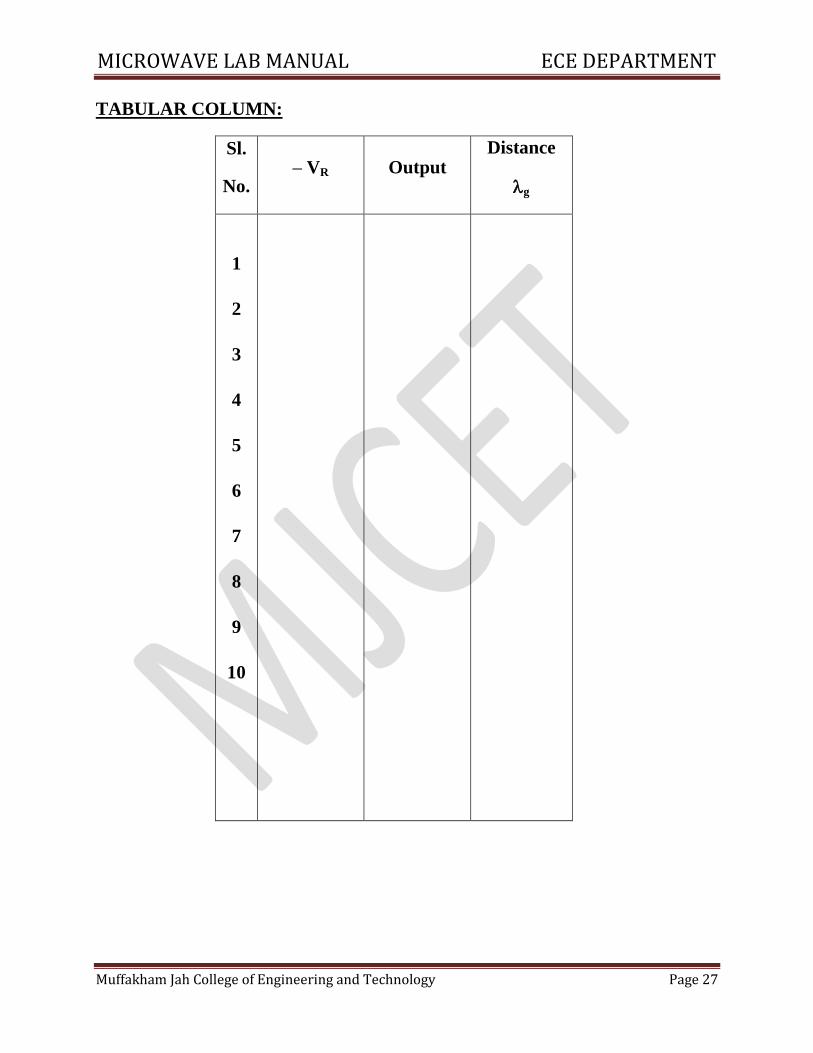
TABULAR COLUMN:
Sl.
No. – VR Output
Distance
g
1
2
3
4
5
6
7
8
9
10
MICROWAVE LAB MANUAL ECE DEPARTMENT
Muffakham Jah College of Engineering and Technology Page 28
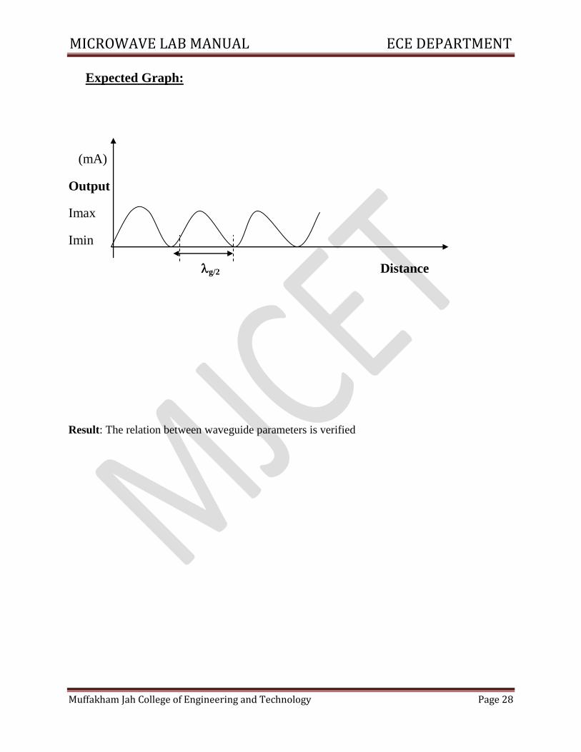
Expected Graph:
(mA)
Output
Imax
Imin
g/2 Distance
Result: The relation between waveguide parameters is verified
MICROWAVE LAB MANUAL ECE DEPARTMENT
Muffakham Jah College of Engineering and Technology Page 29
4.MEASUREMENT OF VSWR
AIM: To determine the Standing-Wave Ratio and Reflection Coefficient.
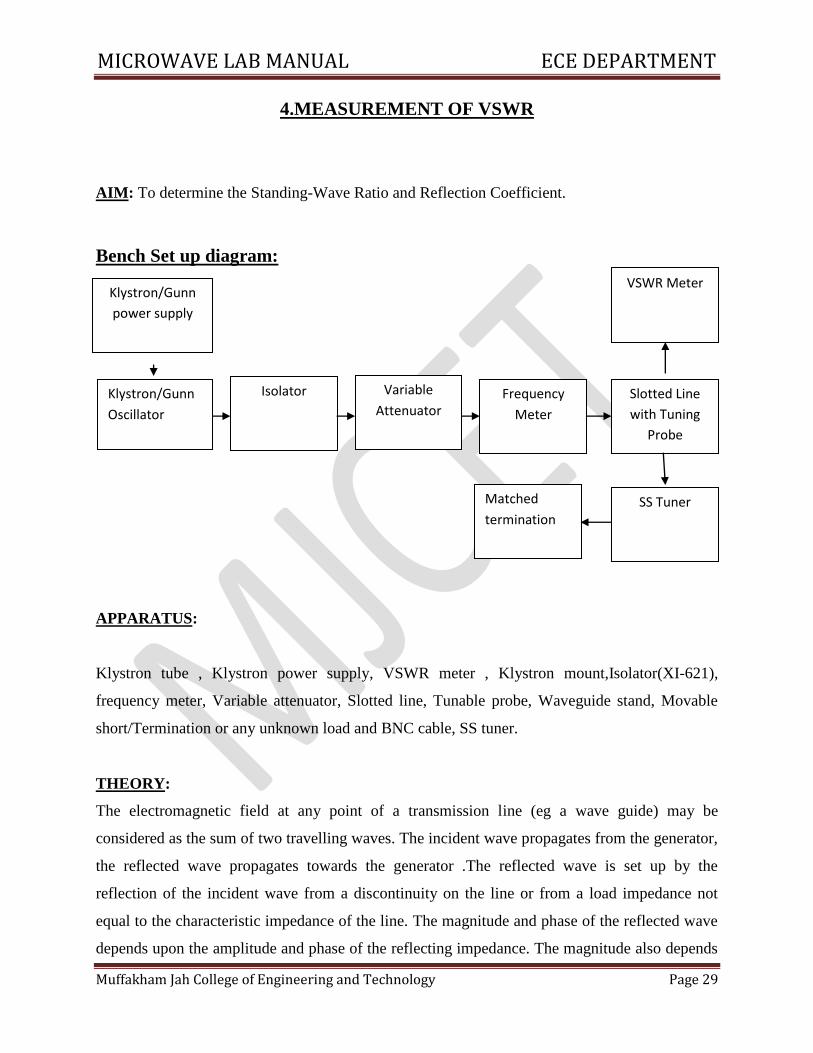
Bench Set up diagram:
APPARATUS:
Klystron tube , Klystron power supply, VSWR meter , Klystron mount,Isolator(XI-621),
frequency meter, Variable attenuator, Slotted line, Tunable probe, Waveguide stand, Movable
short/Termination or any unknown load and BNC cable, SS tuner.
THEORY:
The electromagnetic field at any point of a transmission line (eg a wave guide) may be
considered as the sum of two travelling waves. The incident wave propagates from the generator,
the reflected wave propagates towards the generator .The reflected wave is set up by the
reflection of the incident wave from a discontinuity on the line or from a load impedance not
equal to the characteristic impedance of the line. The magnitude and phase of the reflected wave
depends upon the amplitude and phase of the reflecting impedance. The magnitude also depends
Klystron/Gunn
power supply
Isolator Variable
Attenuator
SS Tuner
Frequency
Meter
Slotted Line
with Tuning
Probe
VSWR Meter
Matched
termination
Klystron/Gunn
Oscillator
MICROWAVE LAB MANUAL ECE DEPARTMENT
Muffakham Jah College of Engineering and Technology Page 30
on the amplitude losses on the line. On a lossy line the reflected (and incident) wave will be
attenuated. If the line is uniform and infinitely long there would be no reflected wave. The same
applies for a line of finite length which is matched i.e. has a load equal to the characteristic
impedance of the line. The presence of two travelling waves gives rise to standing wave along
the line. The electrical (and mechanical) field varies periodically with distance. The maximum
field strength is found where the two waves add in phase and the minimum where the two waves
add in opposite phase. Figure above shows the voltage standing wave patterns for different load
impedances. The distance between two successive minima (or maxima) is half the wavelength on
the transmission line. The ratio between the electrical fields of the reflected and incident wave is
called the voltage reflection coefficient, being a vector, which means that is phase varies along
the transmission line. The voltage standing wave ratio VSWR on a transmission line is defined as
the ratio between maximum and minimum field strengths along the line.
ρ = Er / Ei ,
S = Emax / Emin = (Ei + Er) / (Ei - Er)
Reflection Coefficient =(S – 1) / (S+1)
PROCEDURE:
1. Set up the equipment as shown in the figure.
2. Keep the variable attenuator in minimum position.
3. Keep the control knob of VSWR meter as below
Range - 40dB/50dB
I/p switch - low impedance
Meter switch - normal
Gain - mid position approximate.
4.. Keep the control knob of the Klystron power supply as below.
Beam voltage - OFF
MICROWAVE LAB MANUAL ECE DEPARTMENT
Muffakham Jah College of Engineering and Technology Page 31
Mod switch - AM
Beam voltage knob - fully anti-clockwise
Repeller voltage knob - fully clockwise
AM amplitude knob - around fully clockwise
AM frequency - mid position
5. Switch ON the Klystron power supply, VSWR meter and cooling fan.
6. Switch ON the beam voltage and set beam voltage at 250V.
7. Rotate the reflector voltage knob to get deflection in VSWR meter.
8. Tune the output by turning the reflector voltage, amplitude and frequency of AM modulation.
9. Tune plunger of klystron mount and probe for maximum deflection in VSWR meter.
10. If required change the range dB switch variable attenuator position and gain control knob to
get deflection in the scale of VSWR meter.
A. Measurement of Low and Medium VSWR
1. Move the probe along the slotted section to get maximum deflection in VSWR meter.
2. Adjust the VSWR meter gain control knob or variable attenuator until the meter indicates1.0
on normal VSWR scale.
3. Keep all the control knob as it is, move the probe to next minimum position. Read the VSWR
on scale.
4. Repeat the above step for change of S.S tuner probe depth and record the corresponding SWR.
5. If the VSWR is between 3.2 and 10, change the range dB switch to next higher position and
read SWR on second VSWR scale of 3 to 10.
B. Measurement of high VSWR (Double minimum method)
1. Get the depth of S.S tuner slightly more for maximum VSWR.
2. Move the probe along with slotted line until minimum is indicated.
MICROWAVE LAB MANUAL ECE DEPARTMENT
Muffakham Jah College of Engineering and Technology Page 32
3. Adjust the VSWR meter gain control knob and variable attenuator to obtain a reading of 3 dB
in the normal dB scale (0 to 10 dB) of VSWR meter.
4. Move the probe to the left on slotted line until full scale deflection is obtained on 0-10 dB
scale. Note and record the probe position on slotted line let it be d1.
5. Repeat the step-3 and move the probe right along the slotted line until full scale deflection is
obtained on 0 – 10 dB normal dB scale. Let it be d2.
6. Repeat the S.S tuner and termination by movable short.
7. Measure the distance between two successive minima positions of the probe, twice the
distance is guide wavelength λg.
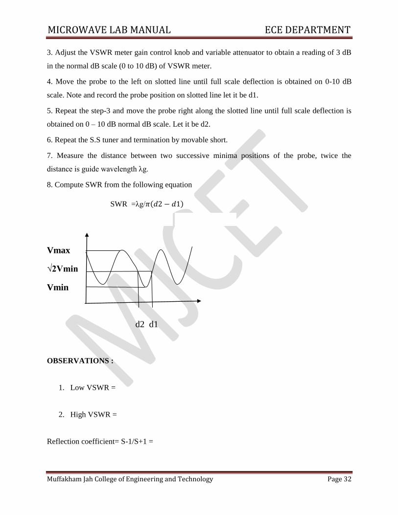
8. Compute SWR from the following equation
SWR =λg/𝜋 𝑑2− 𝑑1
Vmax
√2Vmin
Vmin
d2 d1
OBSERVATIONS :
1. Low VSWR =
2. High VSWR =
Reflection coefficient= S-1/S+1 =
MICROWAVE LAB MANUAL ECE DEPARTMENT
Muffakham Jah College of Engineering and Technology Page 33
5. MEASUREMENT OF IMPEDANCE
AIM: To measure unknown impedance using the Smith chart.
EQUIPMENT :
Klystron Tube, Klystron Power supply, Klystron Mount, Isolator, Frequency Meter, Variable
Attenuator, Slotted line, VSWR Meter, Waveguide Stand, SS tuner, Movable Short/Termination
THEORY :
The impedance at any point on a transmission line can be written in the form R+jX. This SWR
can be calculated S=(1+R) / (1-R)Where R is reflection coefficient = Z-Zo /Z+Zo where Z0 is
the characteristic impedance of the waveguide at the operating frequency. Z is the load
impedance. The unknown device is connected to the slotted section and the position of one
minima is determined. The unknown device is replaced by Movable short to the slotted section.
Two successive minima positions are noted. Twice the difference between the minima positions
will be guide wavelength. One of the minima is used as reference for impedance measurement.
Find the difference of reference minima and minima position obtained from unknown load. Let it
be‘d’. Take a Smith chart, taking ‘l’ as center; draw a circle of radius equal to ‘S0’. Mark a point
on circumference of Smith chart towards load side at a distance equal to d/λg. Join the center
with this point. Find the point where it cuts the drawn circle. The coordinates of this point will
show the normalized impedance of the load.
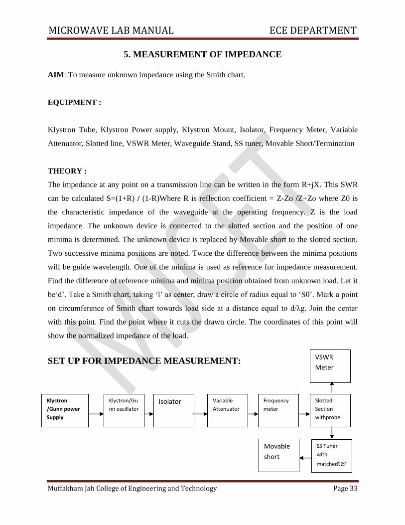
SET UP FOR IMPEDANCE MEASUREMENT:
Klystron
/Gunn power
Supply
Klystron/Gu
nn oscillator Isolator Variable
Attenuator
Frequency
meter
Slotted
Section
withprobe
SS Tuner
with
matchedter
mibnatio
n
Movable
short
VSWR
Meter
MICROWAVE LAB MANUAL ECE DEPARTMENT
Muffakham Jah College of Engineering and Technology Page 34
PROCEDURE :
1. Set up the equipment as shown in the figure.
2. Set the variable attenuator at minimum position.
3. Keep the control knobs of VSWR Meter as below
Range - 50 dB position
Input switch - Crystal Low Impedance
Meter switch - Normal position
Gain (Coarse – fine) - Mid position
4. Keep the control knobs of Klystron power supply as below
Beam voltage switch -‘OFF’
Mod switch - AM
Beam Voltage Knob - Fully anti-clockwise
Reflector voltage - Fully clockwise
AM – amplitude - Around fully clockwise
AM- Frequency Knob - Around Mid position
5. Switch ‘ON’ the Klystron power supply, VSWR meter and Cooling fan.
6. Switch ‘ON’ the Beam Voltage Switch position and set beam voltage at 300 V with the help
of beam voltage knob.
7. Adjust the reflector voltage knob to get some deflection in VSWR meter.
8. Maximize the deflection with AM amplitude and frequency control knob of power supply.
9. Tune the plunger of Klystron Mount for maximum deflection.
10. Tune the reflector voltage knob for maximum deflection.
11. Tune the probe for maximum deflection in VSWR meter.
12. Tune the frequency meter knob to get a ‘dip’ on the VSWR scale, and note down the
frequency directly from frequency meter.
13. Keep the depth of the pin of SS Tuner around 3-4 mm and lock it.
14. Move the probe along the slotted section to get maximum deflection.
MICROWAVE LAB MANUAL ECE DEPARTMENT
Muffakham Jah College of Engineering and Technology Page 35
15. Adjust VSWR meter gain control knob and variable attenuator until the meter indicates 1.0
on the normal dB SWR scale.
16. Move the probe to next minima position and note down the SWR S0 on the scale. Also note
down the probe position, let it be ‘dx’.
17. Remove the SS Tuner and matched termination and place movable short at slotted section.
The plunger of short should be at zero.
18. Note the position of two successive minima position. Let it be d1 and d2. Hence λg = 2(d1 –
d2).
d = dx – d1
19. Calculate d/λg.
20. Find out the normalized impedance as described in the theory section.
21. Repeat the same experiment for other frequency if required.
OBSERVATIONS :
d1 = mm.
d2 = mm
λg = 2(d1 – d2) mm.
SWR = S0 =
d =
d/λg =
Normalized impedance =
PRECAUTIONS :
1. To protect repeller from damage the repeller negative voltage is always applied before anode
voltage.
2. While modulating repeller should never become positive with respect to cavity.
3. Cooling should be provided to Reflex klystron
MICROWAVE LAB MANUAL ECE DEPARTMENT
Muffakham Jah College of Engineering and Technology Page 36
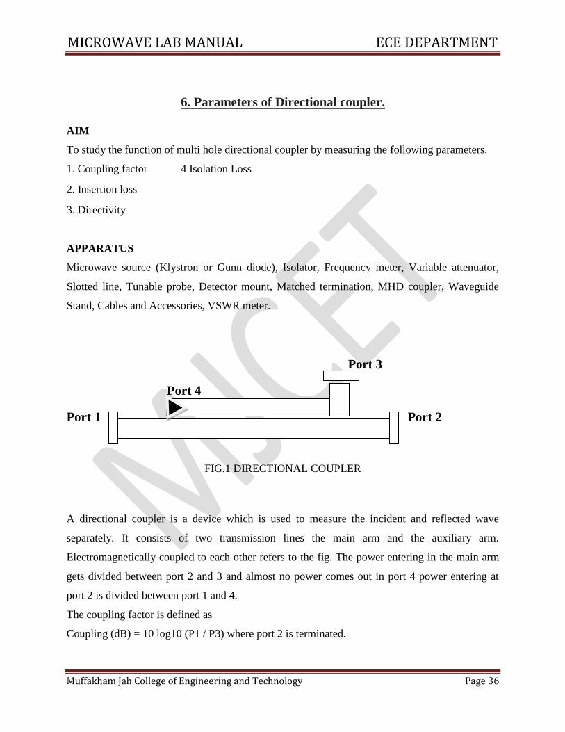
6. Parameters of Directional coupler.
AIM
To study the function of multi hole directional coupler by measuring the following parameters.
1. Coupling factor 4 Isolation Loss
2. Insertion loss
3. Directivity
APPARATUS
Microwave source (Klystron or Gunn diode), Isolator, Frequency meter, Variable attenuator,
Slotted line, Tunable probe, Detector mount, Matched termination, MHD coupler, Waveguide
Stand, Cables and Accessories, VSWR meter.
Port 3
Port 4
Port 1 Port 2
FIG.1 DIRECTIONAL COUPLER
A directional coupler is a device which is used to measure the incident and reflected wave
separately. It consists of two transmission lines the main arm and the auxiliary arm.
Electromagnetically coupled to each other refers to the fig. The power entering in the main arm
gets divided between port 2 and 3 and almost no power comes out in port 4 power entering at
port 2 is divided between port 1 and 4.
The coupling factor is defined as
Coupling (dB) = 10 log10 (P1 / P3) where port 2 is terminated.
MICROWAVE LAB MANUAL ECE DEPARTMENT
Muffakham Jah College of Engineering and Technology Page 37
Isolation (dB) = 10 log 10(P2 / P3) where P1 is matched with built in termination and power
entering at port 1 the directivity of the coupler is a measure of separation between incident wave
and the reflected wave directivity is measured indirectly as follows
Hence directivity D (dB) = 1-c = 10log10 (P2 / P1)
Main line insertion loss is the attenuation introduced in the transmission line by insertion of
coupler. It is defined as
Insertion loss (dB) = 10log10 (P1 / P2).
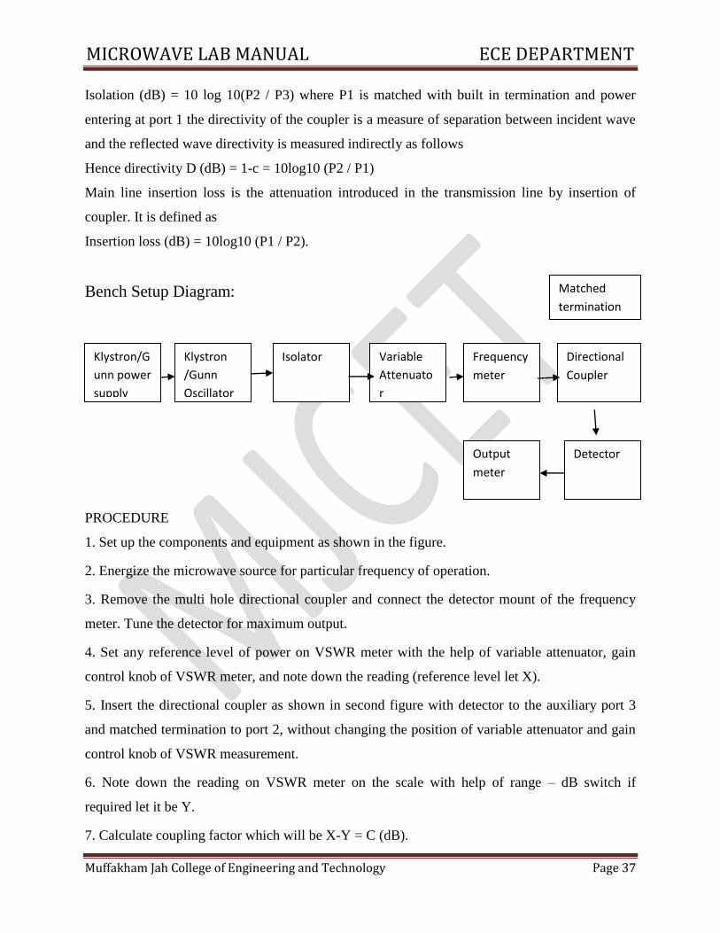
Bench Setup Diagram:
PROCEDURE
1. Set up the components and equipment as shown in the figure.
2. Energize the microwave source for particular frequency of operation.
3. Remove the multi hole directional coupler and connect the detector mount of the frequency
meter. Tune the detector for maximum output.
4. Set any reference level of power on VSWR meter with the help of variable attenuator, gain
control knob of VSWR meter, and note down the reading (reference level let X).
5. Insert the directional coupler as shown in second figure with detector to the auxiliary port 3
and matched termination to port 2, without changing the position of variable attenuator and gain
control knob of VSWR measurement.
6. Note down the reading on VSWR meter on the scale with help of range – dB switch if
required let it be Y.
7. Calculate coupling factor which will be X-Y = C (dB).
Klystron/G
unn power
supply
Klystron
/Gunn
Oscillator
Isolator Variable
Attenuato
r
Frequency
meter
Output
meter
Detector
Directional
Coupler
Matched
termination
MICROWAVE LAB MANUAL ECE DEPARTMENT
Muffakham Jah College of Engineering and Technology Page 38
8. Now carefully disconnect the detector from the auxiliary port 3 and match termination from
point 2 without disturbing the set up.
9. Connect the matched termination to the auxiliary port 3 and detector to port 2 and measure the
reading on VSWR meter, suppose it is Z.
10. Compute the insertion loss X-Z in dB.
11. Repeat the steps from 1 to 4.
12. Connect the directional coupler in the reverse direction i.e. port 2 to frequency meter side
matched termination to port 1 and detector mount to port 3 without disturbing the position of the
variable attenuator and gain control knob of VSWR meter.
13. Measure and note down the reading on VSWR meter. Let it be Yd. X – Yd gives isolation.
14. Compute the directivity as Y – Yd.
15. Repeat the same for other frequencies.
OBSERVATIONS :
Check the condition Isolation Loss = Coupling factor + Directivity
Insertion Loss= 10 log (Pi/Pt)
Coupling factor = 10 log (Pi/Pf)
Directivity =10 log (Pf/Pb)
Isolation Loss= 10 log (Pi/Pb)
Where Pi = input power, Pt = transmitted power Pf = forward power,
Pb =backward power
MICROWAVE LAB MANUAL ECE DEPARTMENT
Muffakham Jah College of Engineering and Technology Page 39
7. SCATTERING MATRICES OF TEES.
AIM: To study the characteristics of waveguide Tees and to find its scattering matrices.
COMPONENTS:
1. Test set up(see previous experiment)
2. Ammeter
3. E-plane Tee
4. H-plane Tee
5. Magic Tee
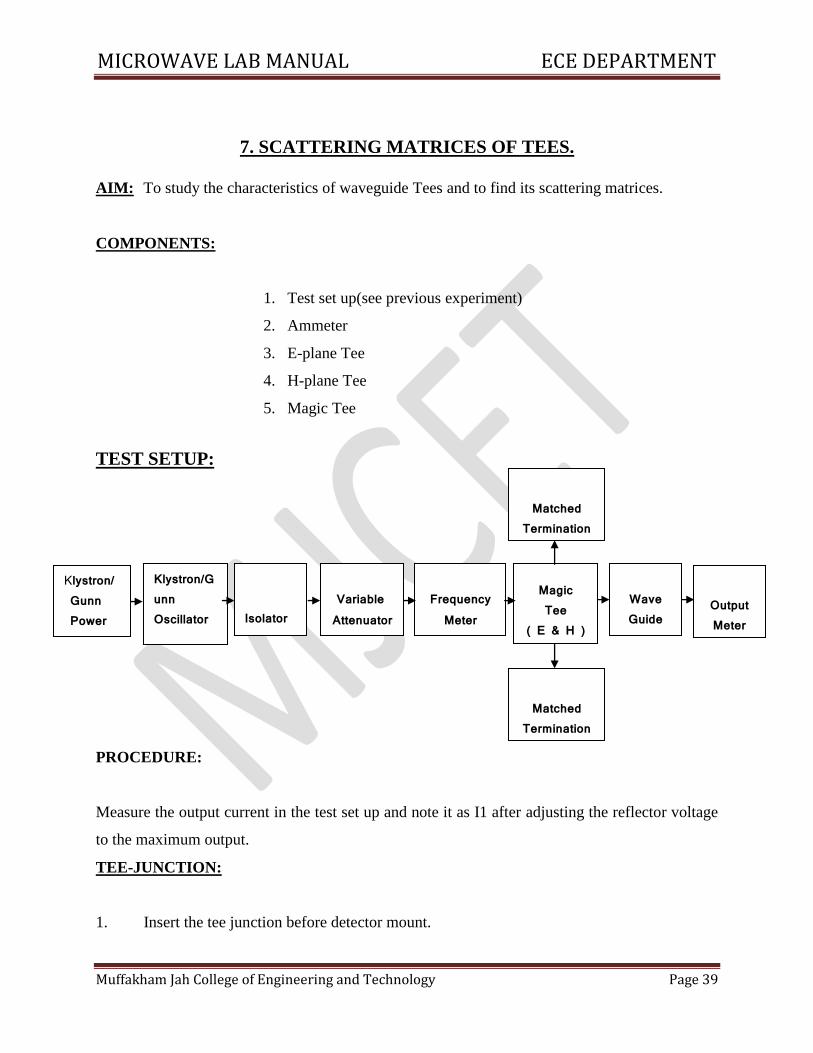
TEST SETUP:
PROCEDURE:
Measure the output current in the test set up and note it as I1 after adjusting the reflector voltage
to the maximum output.
TEE-JUNCTION:
1. Insert the tee junction before detector mount.
Klystron/ Gunn Power Supply
Klystron/Gunn Oscillator
Isolator
Variable Attenuator
Frequency
Meter
Magic Tee
( E & H )
Wave Guide
Detector
Output Meter
Matched Termination
Matched Termination
MICROWAVE LAB MANUAL ECE DEPARTMENT
Muffakham Jah College of Engineering and Technology Page 40
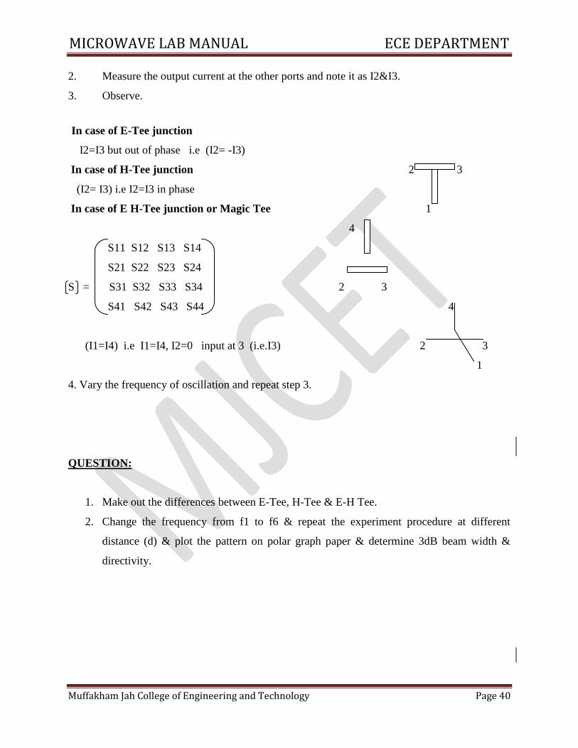
2. Measure the output current at the other ports and note it as I2&I3.
3. Observe.
In case of E-Tee junction
I2=I3 but out of phase i.e (I2= -I3)
In case of H-Tee junction 2 3
(I2= I3) i.e I2=I3 in phase
In case of E H-Tee junction or Magic Tee 1
4
S11 S12 S13 S14
S21 S22 S23 S24
S = S31 S32 S33 S34 2 3
S41 S42 S43 S44 4
(I1=I4) i.e I1=I4, I2=0 input at 3 (i.e.I3) 2 3
1
4. Vary the frequency of oscillation and repeat step 3.
QUESTION:
1. Make out the differences between E-Tee, H-Tee & E-H Tee.
2. Change the frequency from f1 to f6 & repeat the experiment procedure at different
distance (d) & plot the pattern on polar graph paper & determine 3dB beam width &
directivity.
MICROWAVE LAB MANUAL ECE DEPARTMENT
Muffakham Jah College of Engineering and Technology Page 41
8. SCATTRING MATRIX OF CIRCULATOR
AIM: To calculate S matrix of the circulators.
EQUIPMENT:
1. Test set up
2. Ammeter
3. Circulators
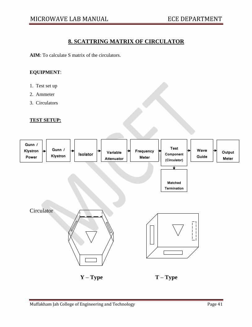
TEST SETUP:
Circulator
Y – Type T – Type
Gunn / Klystron Power Supply
Gunn / Klystron Oscillator
Isolator
Variable Attenuator
Frequency Meter
Test Component (Circulator)
Wave Guide
Detector
Output Meter
Matched
Termination
MICROWAVE LAB MANUAL ECE DEPARTMENT
Muffakham Jah College of Engineering and Technology Page 42
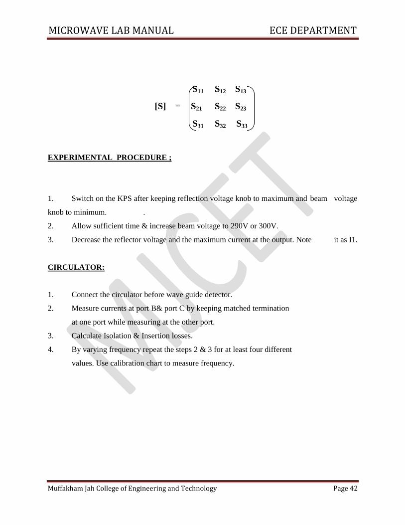
S11 S12 S13
[S] = S21 S22 S23
S31 S32 S33
EXPERIMENTAL PROCEDURE ;
1. Switch on the KPS after keeping reflection voltage knob to maximum and beam voltage
knob to minimum. .
2. Allow sufficient time & increase beam voltage to 290V or 300V.
3. Decrease the reflector voltage and the maximum current at the output. Note it as I1.
CIRCULATOR:
1. Connect the circulator before wave guide detector.
2. Measure currents at port B& port C by keeping matched termination
at one port while measuring at the other port.
3. Calculate Isolation & Insertion losses.
4. By varying frequency repeat the steps 2 & 3 for at least four different
values. Use calibration chart to measure frequency.
MICROWAVE LAB MANUAL ECE DEPARTMENT
Muffakham Jah College of Engineering and Technology Page 43
9. RADIATION PATTERN OF MICROWAVE ANTENNAS
AIM: To determine the relationship between transmitting antenna & receiving antenna and to
measure radiation pattern.
EQUIPMENT:
1. Klystron power supply.
2. Klystron mount with klystron tube ( R. .K.O )
3. Isolator .
4. Frequency meter
5. Slotted section
6. Output meter
7. Crystal detector
8. Horn antennas
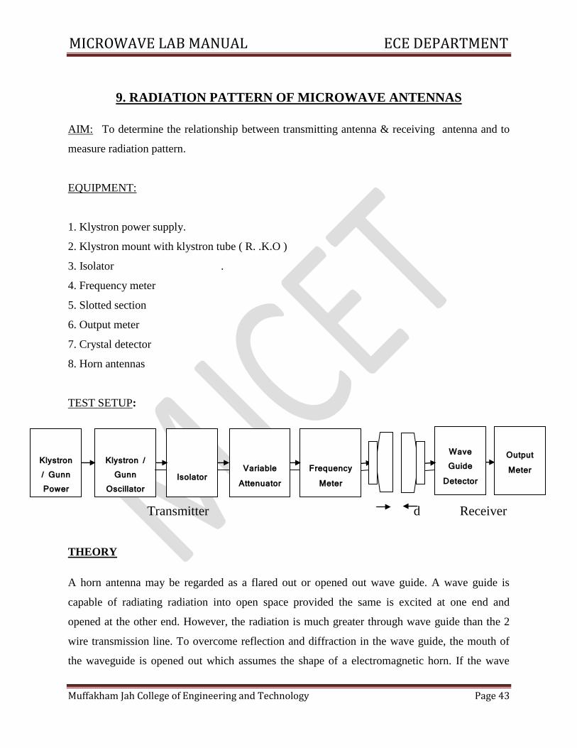
TEST SETUP:
Transmitter d Receiver
THEORY
A horn antenna may be regarded as a flared out or opened out wave guide. A wave guide is
capable of radiating radiation into open space provided the same is excited at one end and
opened at the other end. However, the radiation is much greater through wave guide than the 2
wire transmission line. To overcome reflection and diffraction in the wave guide, the mouth of
the waveguide is opened out which assumes the shape of a electromagnetic horn. If the wave
Klystron / Gunn Power Supply
Klystron / Gunn
Oscillator
Isolator
Variable Attenuator
Frequency Meter
Wave Guide
Detector
Output Meter
MICROWAVE LAB MANUAL ECE DEPARTMENT
Muffakham Jah College of Engineering and Technology Page 44
guide is terminated by any type of horn, the abrupt discontinuity existed is replaced by a gradual
transformation, then all the energy incident in forward direction in the waveguide will now be
radiated, provided the impedance matching is proper. This improves directivity and reduces
diffraction. If flaring is done only in one direction, then sectorial horn is produced. If flaring is
done along both the walls, then pyramidal horn is obtained. By flaring the walls of the circular
waveguide, a concial horn is formed. The fields inside the waveguide propagate in the same
manner as in free space, but on reaching the mouth of the waveguide, these propagating fields
continue to propagate in the same general direction but also starts spreading laterally and the
wave front eventually becomes spherical. However this may be treated as transition region where
the change over from the guided propagation to free space propagation occurs. Since the
waveguide impedance & free space impedance are not equal, hence to avoid standing wave ratio,
flaring of walls of waveguide is done which besides matching of impedance also provide
concentrated radiation pattern(ie)greater directivity and narrower beam width. It is the flared
structure that is given the name electro magnetic horn radiator. The function is to produce a
uniform phase front with a larger aperture in comparison to waveguide and thus directivity is
greater. If flare angle is very large, the wavefront on the mouth of the horn will be curved rather
than plane. This will result in non-uniform phase distribution over the aperture, resulting in
increased beam width and reduced directivity, and vice versa occurs if the flare angle is very
small. The directivity of the horn antenna is given as D = 7.5 A/λ2 where A area of horn mouth
opening. Horn antennas are extensively used at microwave frequencies under the condition that
power gain needed is moderate.
PROCEDURE:
1. Measure the output current in the test set up of transmitter output a frequency(f1) & note it as
I1maximum output.
2. the given attenuator as in the set up and measure the output (power) current & note it as Io, for
the frequency(f1) & repeat the same experimental procedure for various frequencies upto (f6)-
Place Connect the antenna, after the Frequency meter.
3. Connect similar antenna with W.G. detector to the receiving circuit.
4. Turn the receiving Antenna and note the reading for the Near field and also far field pattern.
MICROWAVE LAB MANUAL ECE DEPARTMENT
Muffakham Jah College of Engineering and Technology Page 45
Tabular column:
Near Field d1 = Far Field d2 =
Sl
No. Angle Output
Sl
No. Angle Output
1
2
3
4
5
6
7
8
9
10
1
2
3
4
5
6
7
8
9
10
MICROWAVE LAB MANUAL ECE DEPARTMENT
Muffakham Jah College of Engineering and Technology Page 46
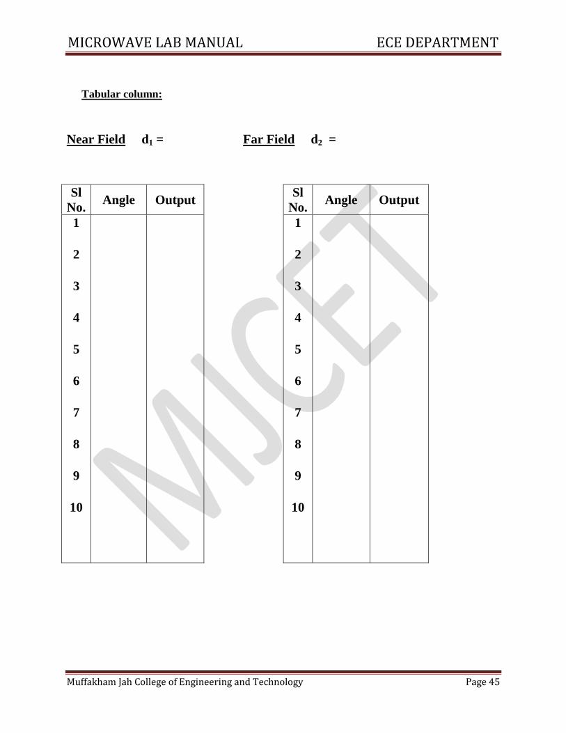
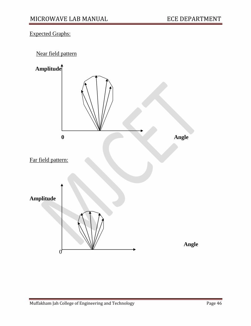
Expected Graphs:
Near field pattern
Amplitude
0 Angle
Far field pattern:
Amplitude
Angle
0
MICROWAVE LAB MANUAL ECE DEPARTMENT
Muffakham Jah College of Engineering and Technology Page 47
10. STUDY OF VARIOUS MICROWAVE ANTENNAS
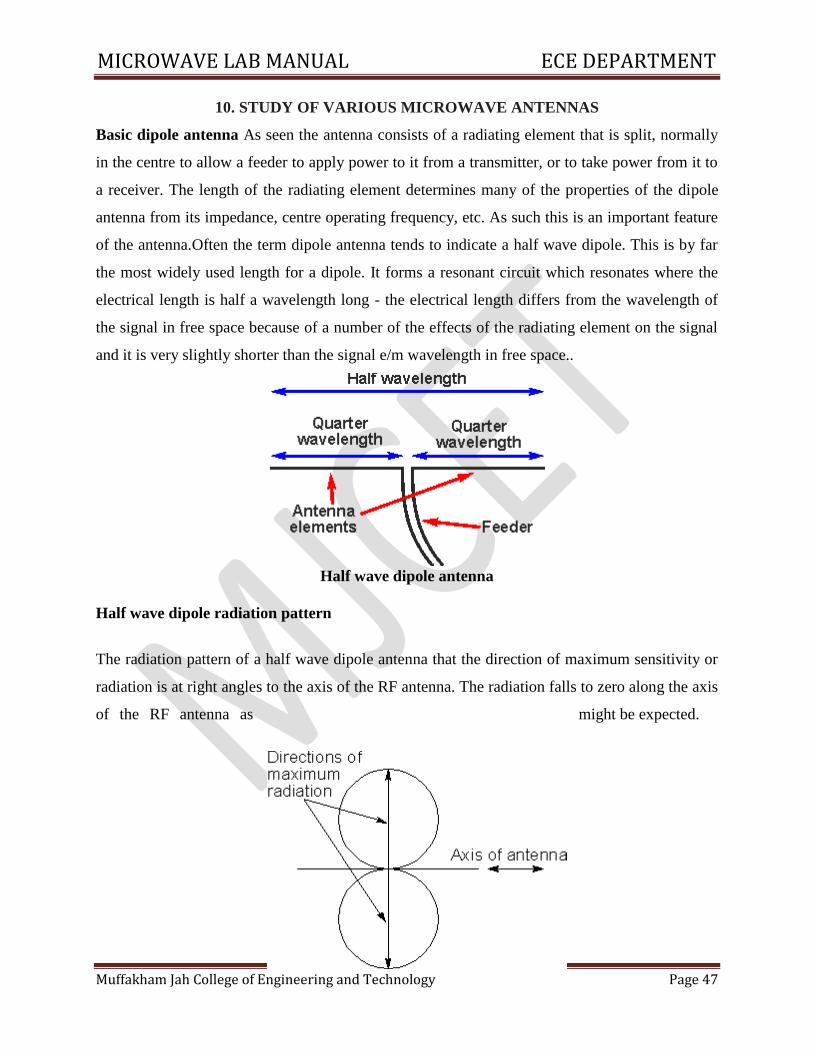
Basic dipole antenna As seen the antenna consists of a radiating element that is split, normally
in the centre to allow a feeder to apply power to it from a transmitter, or to take power from it to
a receiver. The length of the radiating element determines many of the properties of the dipole
antenna from its impedance, centre operating frequency, etc. As such this is an important feature
of the antenna.Often the term dipole antenna tends to indicate a half wave dipole. This is by far
the most widely used length for a dipole. It forms a resonant circuit which resonates where the
electrical length is half a wavelength long - the electrical length differs from the wavelength of
the signal in free space because of a number of the effects of the radiating element on the signal
and it is very slightly shorter than the signal e/m wavelength in free space..
Half wave dipole antenna
Half wave dipole radiation pattern
The radiation pattern of a half wave dipole antenna that the direction of maximum sensitivity or
radiation is at right angles to the axis of the RF antenna. The radiation falls to zero along the axis
of the RF antenna as might be expected.
MICROWAVE LAB MANUAL ECE DEPARTMENT
Muffakham Jah College of Engineering and Technology Page 48
Radiation pattern of a half wave dipole antenna in free space
In a three dimensional plot, the radiation pattern envelope for points of equal radiation intensity
for a doughnut type shape, with the axis of the antenna passing through the hole in the centre of
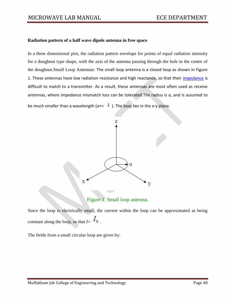
the doughnut.Small Loop Antennas: The small loop antenna is a closed loop as shown in Figure
1. These antennas have low radiation resistance and high reactance, so that their impedance is
difficult to match to a transmitter. As a result, these antennas are most often used as receive
antennas, where impedance mismatch loss can be tolerated.The radius is a, and is assumed to
be much smaller than a wavelength (a<< ). The loop lies in the x-y plane.
Figure 1. Small loop antenna.
Since the loop is electrically small, the current within the loop can be approximated as being
constant along the loop, so that I= .
The fields from a small circular loop are given by:
MICROWAVE LAB MANUAL ECE DEPARTMENT
Muffakham Jah College of Engineering and Technology Page 49
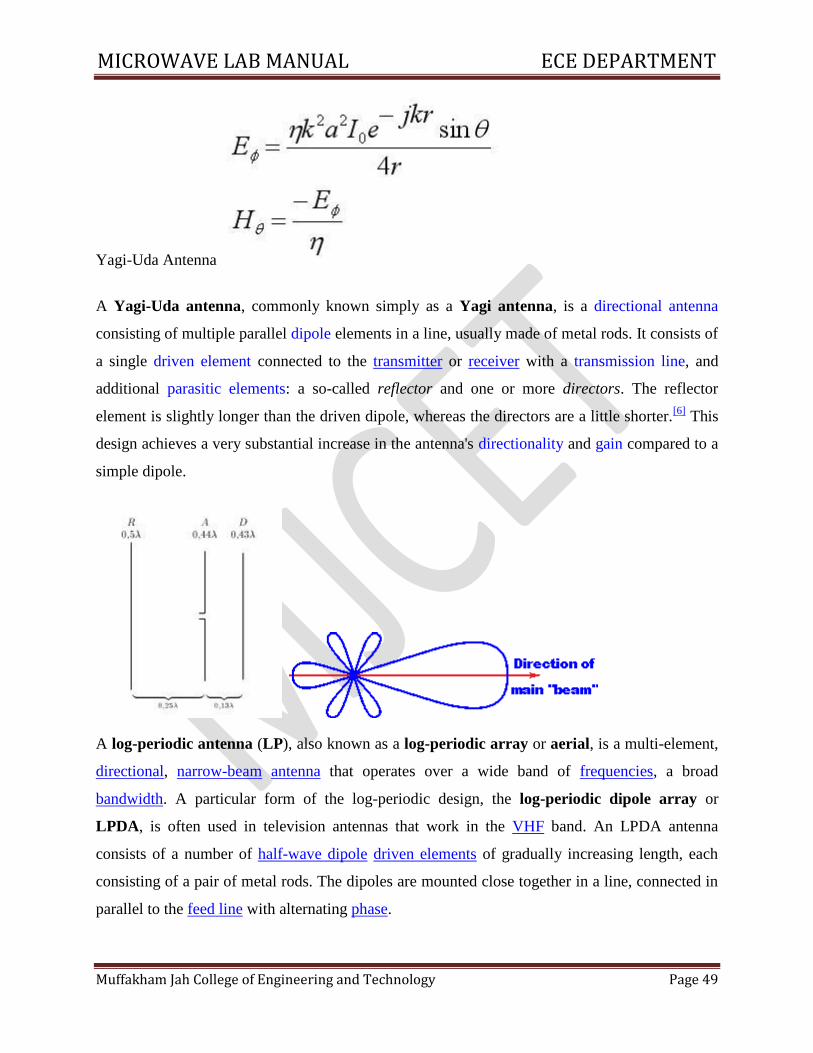
Yagi-Uda Antenna
A Yagi-Uda antenna, commonly known simply as a Yagi antenna, is a directional antenna
consisting of multiple parallel dipole elements in a line, usually made of metal rods. It consists of
a single driven element connected to the transmitter or receiver with a transmission line, and
additional parasitic elements: a so-called reflector and one or more directors. The reflector
element is slightly longer than the driven dipole, whereas the directors are a little shorter.[6]
This
design achieves a very substantial increase in the antenna's directionality and gain compared to a
simple dipole.
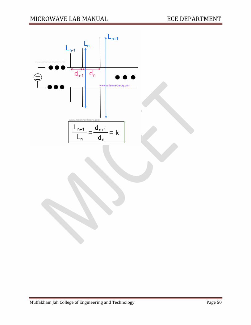
A log-periodic antenna (LP), also known as a log-periodic array or aerial, is a multi-element,
directional, narrow-beam antenna that operates over a wide band of frequencies, a broad
bandwidth. A particular form of the log-periodic design, the log-periodic dipole array or
LPDA, is often used in television antennas that work in the VHF band. An LPDA antenna
consists of a number of half-wave dipole driven elements of gradually increasing length, each
consisting of a pair of metal rods. The dipoles are mounted close together in a line, connected in
parallel to the feed line with alternating phase.
MICROWAVE LAB MANUAL ECE DEPARTMENT
Muffakham Jah College of Engineering and Technology Page 50
MICROWAVE LAB MANUAL ECE DEPARTMENT
Muffakham Jah College of Engineering and Technology Page 51
11.MINI PROJECT
Aim: To design microwave components such as Directional Coupler,
Circulators and antenna arrays using simulation software.
Students are encouraged to design various microwave components and
antenna arrays using simulation software.
MICROWAVE LAB MANUAL ECE DEPARTMENT
Muffakham Jah College of Engineering and Technology Page 52
APPENDIX
LABORATORY COURSE ASSESSMENT GUIDELINES
i. The number of experiments in each laboratory course shall be as per the curriculum in the
scheme of instructions provided by OU. Mostly the number of experiments is 10 in each
laboratory course under semester scheme and 18 under year wise scheme.
ii. The students will maintain a separate note book for observations in each laboratory
course.
iii. In each session the students will conduct the allotted experiment and enter the data in the
observation table.
iv. The students will then complete the calculations and obtain the results. The course
coordinator will certify the result in the same session.
v. The students will submit the record in the next class. The evaluation will be continuous
and not cycle-wise or at semester end.
vi. The internal marks of 25 are awarded in the following manner:
a. Laboratory record - Maximum Marks 15
b. Test and Viva Voce - Maximum Marks 10
vii. Laboratory Record: Each experimental record is evaluated for a score of 50. The rubric
parameters are as follows: a. Write up format - Maximum Score 15
b. Experimentation Observations & Calculations - Maximum Score 20
c. Results and Graphs - Maximum Score 10
d. Discussion of results - Maximum Score 5
While (a), (c) and (d) are assessed at the time of record submission, (b) is assessed during the
session based on the observations and calculations. Hence if a student is absent for an experiment
but completes it in another session and subsequently submits the record, it shall be evaluated for
a score of 30 and not 50.
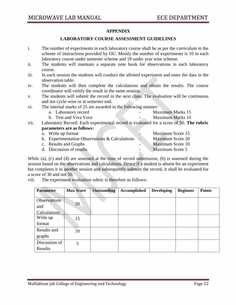
viii. The experiment evaluation rubric is therefore as follows:
Parameter Max Score Outstanding Accomplished Developing Beginner Points
Observations
and
Calculations
20
Write up
format 15
Results and
graphs 10
Discussion of
Results 5
MICROWAVE LAB MANUAL ECE DEPARTMENT
Muffakham Jah College of Engineering and Technology Page 53
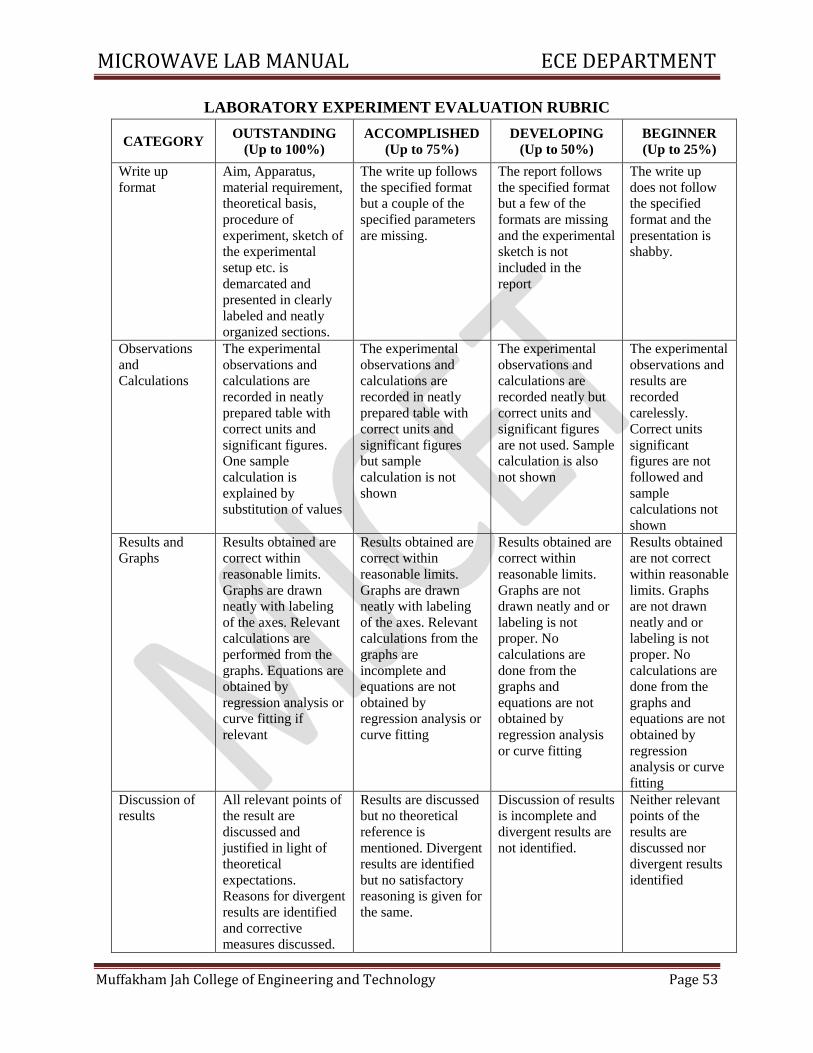
LABORATORY EXPERIMENT EVALUATION RUBRIC
CATEGORY OUTSTANDING
(Up to 100%)
ACCOMPLISHED
(Up to 75%)
DEVELOPING
(Up to 50%)
BEGINNER
(Up to 25%)
Write up
format
Aim, Apparatus,
material requirement,
theoretical basis,
procedure of
experiment, sketch of
the experimental
setup etc. is
demarcated and
presented in clearly
labeled and neatly
organized sections.
The write up follows
the specified format
but a couple of the
specified parameters
are missing.
The report follows
the specified format
but a few of the
formats are missing
and the experimental
sketch is not
included in the
report
The write up
does not follow
the specified
format and the
presentation is
shabby.
Observations
and
Calculations
The experimental
observations and
calculations are
recorded in neatly
prepared table with
correct units and
significant figures.
One sample
calculation is
explained by
substitution of values
The experimental
observations and
calculations are
recorded in neatly
prepared table with
correct units and
significant figures
but sample
calculation is not
shown
The experimental
observations and
calculations are
recorded neatly but
correct units and
significant figures
are not used. Sample
calculation is also
not shown
The experimental
observations and
results are
recorded
carelessly.
Correct units
significant
figures are not
followed and
sample
calculations not
shown
Results and
Graphs
Results obtained are
correct within
reasonable limits.
Graphs are drawn
neatly with labeling
of the axes. Relevant
calculations are
performed from the
graphs. Equations are
obtained by
regression analysis or
curve fitting if
relevant
Results obtained are
correct within
reasonable limits.
Graphs are drawn
neatly with labeling
of the axes. Relevant
calculations from the
graphs are
incomplete and
equations are not
obtained by
regression analysis or
curve fitting
Results obtained are
correct within
reasonable limits.
Graphs are not
drawn neatly and or
labeling is not
proper. No
calculations are
done from the
graphs and
equations are not
obtained by
regression analysis
or curve fitting
Results obtained
are not correct
within reasonable
limits. Graphs
are not drawn
neatly and or
labeling is not
proper. No
calculations are
done from the
graphs and
equations are not
obtained by
regression
analysis or curve
fitting
Discussion of
results
All relevant points of
the result are
discussed and
justified in light of
theoretical
expectations.
Reasons for divergent
results are identified
and corrective
measures discussed.
Results are discussed
but no theoretical
reference is
mentioned. Divergent
results are identified
but no satisfactory
reasoning is given for
the same.
Discussion of results
is incomplete and
divergent results are
not identified.
Neither relevant
points of the
results are
discussed nor
divergent results
identified
MICROWAVE LAB MANUAL ECE DEPARTMENT
Muffakham Jah College of Engineering and Technology Page 54
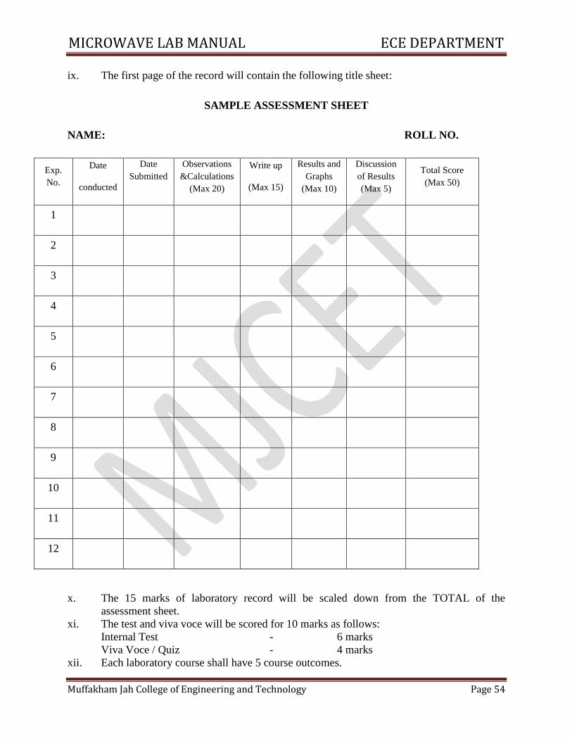
ix. The first page of the record will contain the following title sheet:
SAMPLE ASSESSMENT SHEET
NAME: ROLL NO.
Exp.
No.
Date
conducted
Date
Submitted
Observations
&Calculations
(Max 20)
Write up
(Max 15)
Results and
Graphs
(Max 10)
Discussion
of Results
(Max 5)
Total Score
(Max 50)
1
2
3
4
5
6
7
8
9
10
11
12
x. The 15 marks of laboratory record will be scaled down from the TOTAL of the
assessment sheet.
xi. The test and viva voce will be scored for 10 marks as follows:
Internal Test - 6 marks
Viva Voce / Quiz - 4 marks
xii. Each laboratory course shall have 5 course outcomes.
MICROWAVE LAB MANUAL ECE DEPARTMENT
Muffakham Jah College of Engineering and Technology Page 55
The proposed course outcomes are as follows:
On successful completion of the course, the student will acquire the ability to:
1. Conduct experiments, take measurements and analyze the data through hands-on
experience in order to demonstrate understanding of the theoretical concepts of
_______________________, while working in small groups.
2. Demonstrate writing skills through clear laboratory reports.
3. Employ graphics packages for drawing of graphs and use computational software for
statistical analysis of data.
4. Compare the experimental results with those introduced in lecture, draw relevant
conclusions and substantiate them satisfactorily.
5. Transfer group experience to individual performance of experiments and demonstrate
effective oral communication skills.
xiii. The Course coordinators would prepare the assessment matrix in accordance with the
guidelines provided above for the five course outcomes. The scores to be entered against
each of the course outcome would be the sum of the following as obtained from the
assessment sheet in the record:
a. Course Outcome 1: Sum of the scores under ‘Observations and Calculations’.
b. Course Outcome 2: Sum of the scores under ‘Write up’.
c. Course Outcome 3: Sum of the scores under ‘Results and Graphs’.
d. Course Outcome 4: Sum of the scores under ‘Discussion of Results’.
e. Course Outcome 5: Marks for ‘Internal Test and Viva voce’.
xiv. Soft copy of the assessment matrix would be provided to the course coordinators.
MICROWAVE LAB MANUAL ECE DEPARTMENT
Muffakham Jah College of Engineering and Technology Page 56
MUFFAKHAM JAH COLLEGE OF ENGINEERING AND TECHNOLOGY
Program Outcomes of B.E (ECE) Program:
PO1: Engineering knowledge: Apply the knowledge of mathematics, science, engineering fundamentals, and an
engineering specialization to the solution of complex engineering problems.
PO2: Problem analysis: Identify, formulate, research literature, and analyse complex engineering problems reaching
substantiated conclusions using first principles of mathematics, natural sciences, and engineering sciences
PO3: Design/development of solutions: Design solutions for complex engineering problems and design system
components or processes that meet the specified needs with appropriate consideration for the public health and
safety, and the cultural, societal, and environmental considerations.
PO4: Conduct investigations of complex problems: Use research-based knowledge and research methods including
design of experiments, analysis and interpretation of data, and synthesis of the information to provide valid
conclusions.
PO5: Modern tool usage: Create, select, and apply appropriate techniques, resources, and modern engineering and
IT tools including prediction and modeling to complex engineering activities with an understanding of the
limitations.
PO6: The engineer and society: Apply reasoning informed by the contextual knowledge to assess societal, health,
safety, legal, and cultural issues and the consequent responsibilities relevant to the professional engineering practice.
PO7: Environment and sustainability: Understand the impact of the professional engineering solutions in societal
and environmental contexts, and demonstrate the knowledge of, and need for sustainable development.
PO8: Ethics: Apply ethical principles and commit to professional ethics and responsibilities and norms of the
engineering practice.
PO9: Individual and team work: Function effectively as an individual, and as a member or leader in diverse teams,
and in multidisciplinary settings.
PO10: Communication: Communicate effectively on complex engineering activities with the engineering
community and with society at large, such as, being able to comprehend and write effective reports and design
documentation, make effective presentations, and give and receive clear instructions.
PO11: Project management and finance: Demonstrate knowledge and understanding of the engineering and
management principles and apply these to one’s own work, as a member and leader in a team, to manage projects
and in multidisciplinary environments.
PO 12: Life-long learning: Recognise the need for, and have the preparation and ability to engage in independent
and life-long learning in the broadest context of technological change.
Program Specific Outcomes (PSOs) of ECE Department, MJCET
PSO1: The ECE Graduates will acquire state of art analysis and design skills in the areas of digital and analog VLSI
Design using modern CAD tools.
PSO2: The ECE Graduates will develop preliminary skills and capabilities necessary for embedded system design
and demonstrate understanding of its societal impact.
PSO3: The ECE Graduates will obtain the knowledge of the working principles of modern communication systems
and be able to develop simulation models of components of a communication system.
PSO4: The ECE Graduates will develop soft skills, aptitude and programming skills to be employable in IT sector.
Related Documents