Subject to change without notice Product Data Catalog Manufacturer’s Name: Saudi Airconditioning Manufacturing Co. Ltd. Country of origin : Jeddah, Saudi Arabia Nearest port of embarkation: Jeddah Islamic port Product classification: Commercial and Residential 42TXP – 60Hz Nominal Cooling Capacity 1.5 – 5.0 Tons HFC R-410A Refrigerant 42TX Direct Expansion fan coil units are available in 6 sizes with nominal cooling capacity range from 1.5 to 5.0 Tons. Each unit is designed to occupy a minimum space. No complex system controls are required for Carrier fan coil units. Piping, drain, and wiring connections are readily accessible and mounting holes and slots are predrilled to save installation time and field labor expense. Contact your local Carrier representative for additional reference materials. 42TXP Fan Coil Units – 60Hz Quality Assurance Certificate Reg. No: 04 100 950420 Page 1

Welcome message from author
This document is posted to help you gain knowledge. Please leave a comment to let me know what you think about it! Share it to your friends and learn new things together.
Transcript

Subject to change without notice Product Data Catalog Manufacturer’s Name: Saudi Airconditioning Manufacturing Co. Ltd. Country of origin : Jeddah, Saudi Arabia Nearest port of embarkation: Jeddah Islamic port Product classification: Commercial and Residential
42TXP – 60Hz
Nominal Cooling Capacity 1.5 – 5.0 Tons HFC R -410A Refrigerant
42TX Direct Expansion fan coil units are available in 6 sizes with nominal cooling capacity range from 1.5 to 5.0 Tons. Each unit is designed to occupy a minimum space. No complex system controls are required for Carrier fan coil units. Piping, drain, and wiring connections are readily accessible and mounting holes and slots are predrilled to save installation time and field labor expense. Contact your local Carrier representative for additional reference materials.
42TXP Fan Coil Units – 60Hz
Quality Assurance Certificate Reg. No: 04 100 950420
Page 1

Table of Contents
Features / Benefits .......................................................................................................................................................... 2
Model Number Nomenclature ......................................................................................................................................... 3
Physical Data .................................................................................................................................................................. 4
Base Unit Dimensions ................................................................................................................................................... 5
Combination Matrix and Ratings ..................................................................................................................................... 6
Electrical Data ................................................................................................................................................................. 6
Typical Wiring Schematic ............................................................................................................................................... 7
Detailed Performance Data ............................................................................................................................................ 7
Fan Performance / Sound Pressure ............................................................................................................................. 10
Controller For Ducted Fan Coil Units ............................................................................................................................ 11
Application Data ............................................................................................................................................................ 13
Options and Accessories .............................................................................................................................................. 14
Guide Specification ....................................................................................................................................................... 15
Features / Benefits
• Every compact one-piece unit arrives fully assembled, tested, and ready to run • Designed especially for high ambient environment • EER (Energy Efficiency Ratio) ratings of up to 11.5 • Standard wired control board kit to control the unit functions, with additional remote control • The drain pan is polyester powder coated for extra protection • Piping connection are field exchangeable; standard factory setup right hand side • Direct drive forward curved centrifugal fan • 3 speed motor • Standard galvanized sheet metal casing • Low unit height suitable for low false ceiling application • Washable aluminum filter • Easy installation and maintenance • ½ inch thickness internal insulation with 24 kg/m^3 density • Low noise level suitable for all application • Sweat connections for easy installation and maintenance
Carrier’s 42TXP direct expansion fan coils are designed to cover low to medium range of air handling requirements. They are compact and ready to fit in the under ceiling application. All units come with solid-state fan controls, 1/2-in. insulation, quiet multi-speed motors, and fully wet coils. Units can accommodate factor supplied field installed heaters from 2 to 4kw. 42TXP are designed for ease of service in under ceiling applications. A carton template for easy location of mounting hardware simplifies installation. Coils are made of double wavy aluminum fins mechanically bonded to copper tubes for superior heat transfer. Direct drive forward curved centrifugal fan attached to 3-speed high efficiency motors. Galvanized sheet metal casing protects against rust and drain pan is polyester powder coated for extra protection. Electrical heater is available option while the control board with the integrated thermostat, remote control and washable Aluminum filters are standard feature. Piping connections position (RH/LH) is optional, and field interchangeable for various applications.
Page 2

Model Number Nomenclature - 42TXP - R410A Series1 2 3 4 5 6 7 8 9 10 11 12 13 14 154 2 T X P 0 1 8 - 3 3 1 C R E
Notes:• FIH - Factory Supplied - Field Installed Electic Heaters Available - See Options and Accessories.
Design Series 2 = 2nd Design Series (Size 60 Only) 3 = 3rd Design Series
Packaging 1 = Standard
Connection Side R = Right Hand L = Left Hand
Controls A = None E = Electronic
Model Type 42 Series Low Height Fan Coils
Model Series TX = Direct Expansion
Refrigerant Type P = R-410A Series
Unit Size 018 = 18,000 Btuh 024 = 24,000 Btuh 030 = 30,000 Btuh 036 = 36,000 Btuh 048 = 48,000 Btuh 060 = 60,000 Btuh
Power Supply (V/Ph/Hz) 3 = 230/1/60
Design Review — = Factory Assigned
Factory Installed Option C = Cool Only
Page 3

Physical Data - 42TXP SeriesUnit Model 42TXP18 42TXP24 42TXP30 42TXP36 42TXP48 42TXP60-32 42TXP60-33Unit size (Tons) 1.5 2.0 2.5 3.0 4.0 5.0 5.0Power SupplyMotor HP 1/2Number of Motors, Speeds 1, 5 SpeedEvaporator CoilCoil Material (HP Tube)Coil Material (Finplate)Coil Face Area, m^2 0.21 0.26 0.31 0.44Number of RowsFin Denisty/ InchCoil Connection TypeCoil Suction Connection Size, InchCoil Liquid Connection Size, InchDrain Diameter InchRefrigerant Metering DeviceSize 52 55 65 70 70BlowerBlower Diameter / Width, mm 180 / 240Filter TypeFilter Qty. / Size (mm) 1 / 847x262 2 / 525x262 2 / 630x262 2 / 630x365Unit DimensionsWidth, mm 1052 1262Depth, mm 656Height, mmNet Weight, kg 32 39 43 49 60
2, 3 Speed
56275 375
Direct drive forward curved centrifugal fan156 / 220
Washable Aluminum Filter2 / 735x365
1682
156 / 170
600
15
1472
AccuRater
14
156 / 220
1
230V-1Ph-60Hz
Aluminum0.52
84
5/8 3/43/8
1/101/151, 3 Speed
3/8" Grooved copper tubes
1/10
Sweat Type
3
Page 4
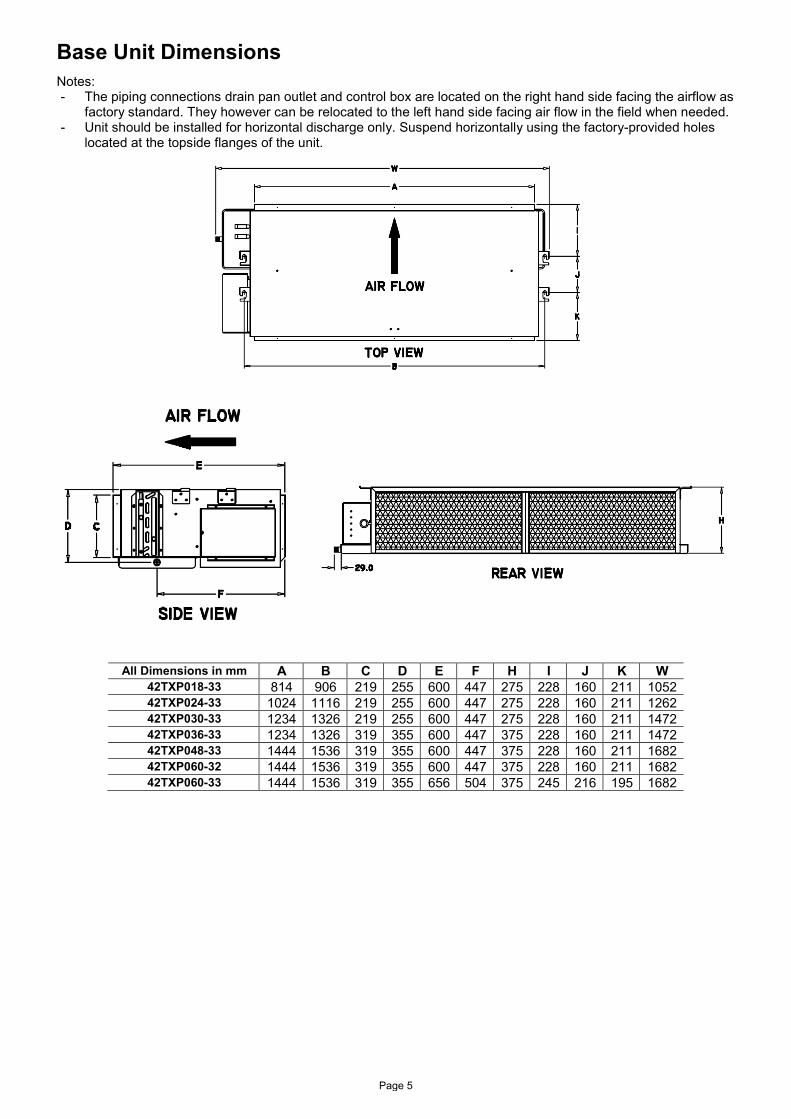
Base Unit Dimensions Notes: - The piping connections drain pan outlet and control box are located on the right hand side facing the airflow as
factory standard. They however can be relocated to the left hand side facing air flow in the field when needed. - Unit should be installed for horizontal discharge only. Suspend horizontally using the factory-provided holes
located at the topside flanges of the unit.
All Dimensions in mm A B C D E F H I J K W 42TXP018-33 814 906 219 255 600 447 275 228 160 211 1052 42TXP024-33 1024 1116 219 255 600 447 275 228 160 211 1262 42TXP030-33 1234 1326 219 255 600 447 275 228 160 211 1472 42TXP036-33 1234 1326 319 355 600 447 375 228 160 211 1472 42TXP048-33 1444 1536 319 355 600 447 375 228 160 211 1682 42TXP060-32 1444 1536 319 355 600 447 375 228 160 211 1682 42TXP060-33 1444 1536 319 355 656 504 375 245 216 195 1682
Page 5
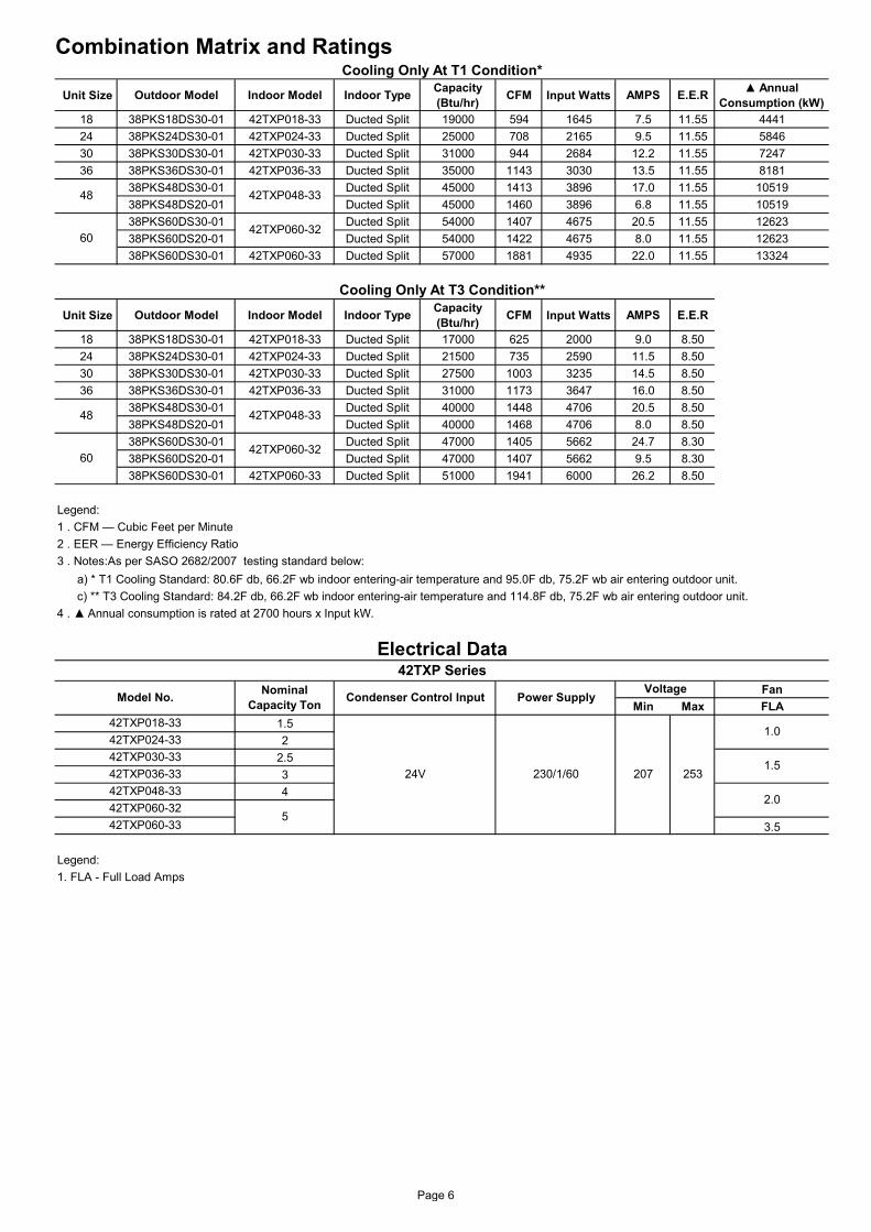
Combination Matrix and Ratings
Unit Size Outdoor Model Indoor Model Indoor Type Capacity (Btu/hr) CFM Input Watts AMPS E.E.R ▲ Annual
Consumption (kW)18 38PKS18DS30-01 42TXP018-33 Ducted Split 19000 594 1645 7.5 11.55 444124 38PKS24DS30-01 42TXP024-33 Ducted Split 25000 708 2165 9.5 11.55 584630 38PKS30DS30-01 42TXP030-33 Ducted Split 31000 944 2684 12.2 11.55 724736 38PKS36DS30-01 42TXP036-33 Ducted Split 35000 1143 3030 13.5 11.55 8181
38PKS48DS30-01 Ducted Split 45000 1413 3896 17.0 11.55 1051938PKS48DS20-01 Ducted Split 45000 1460 3896 6.8 11.55 1051938PKS60DS30-01 Ducted Split 54000 1407 4675 20.5 11.55 1262338PKS60DS20-01 Ducted Split 54000 1422 4675 8.0 11.55 1262338PKS60DS30-01 42TXP060-33 Ducted Split 57000 1881 4935 22.0 11.55 13324
Unit Size Outdoor Model Indoor Model Indoor Type Capacity (Btu/hr) CFM Input Watts AMPS E.E.R
18 38PKS18DS30-01 42TXP018-33 Ducted Split 17000 625 2000 9.0 8.5024 38PKS24DS30-01 42TXP024-33 Ducted Split 21500 735 2590 11.5 8.5030 38PKS30DS30-01 42TXP030-33 Ducted Split 27500 1003 3235 14.5 8.5036 38PKS36DS30-01 42TXP036-33 Ducted Split 31000 1173 3647 16.0 8.50
38PKS48DS30-01 Ducted Split 40000 1448 4706 20.5 8.5038PKS48DS20-01 Ducted Split 40000 1468 4706 8.0 8.5038PKS60DS30-01 Ducted Split 47000 1405 5662 24.7 8.3038PKS60DS20-01 Ducted Split 47000 1407 5662 9.5 8.3038PKS60DS30-01 42TXP060-33 Ducted Split 51000 1941 6000 26.2 8.50
Legend:1 . CFM — Cubic Feet per Minute2 . EER — Energy Efficiency Ratio3 . Notes:As per SASO 2682/2007 testing standard below:
FanMin Max FLA
1.52
2.534
3.5
Legend:1. FLA - Full Load Amps
42TXP060-32
Electrical Data
Voltage
52.0
42TXP036-33
Cooling Only At T1 Condition*
a) * T1 Cooling Standard: 80.6F db, 66.2F wb indoor entering-air temperature and 95.0F db, 75.2F wb air entering outdoor unit.
Cooling Only At T3 Condition**
48 42TXP048-33
48 42TXP048-33
42TXP060-32
60
60
4 . ▲ Annual consumption is rated at 2700 hours x Input kW.
Nominal Capacity Ton
c) ** T3 Cooling Standard: 84.2F db, 66.2F wb indoor entering-air temperature and 114.8F db, 75.2F wb air entering outdoor unit.
42TXP Series
1.0
1.5
Condenser Control Input Power SupplyModel No.
42TXP018-3342TXP024-3342TXP030-33
42TXP060-33
24V 230/1/60 207 25342TXP048-3342TXP060-32
Page 6

Typical Wiring Schematic Applicable for:
• 42TXP018-33 • 42TXP024-33 • 42TXP030-33 • 42TXP036-33 • 42TXP048-33 • 42TXP060-32
Page 7
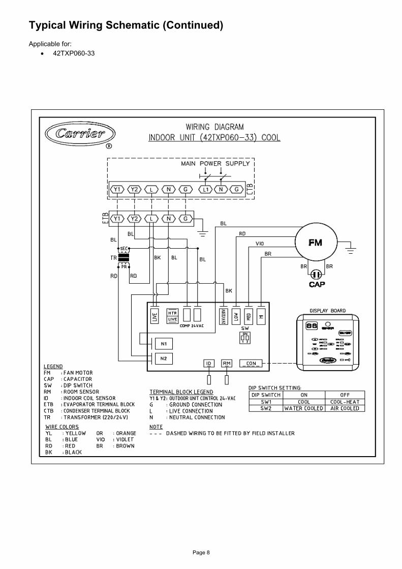
Typical Wiring Schematic (Continued) Applicable for:
• 42TXP060-33
Page 8
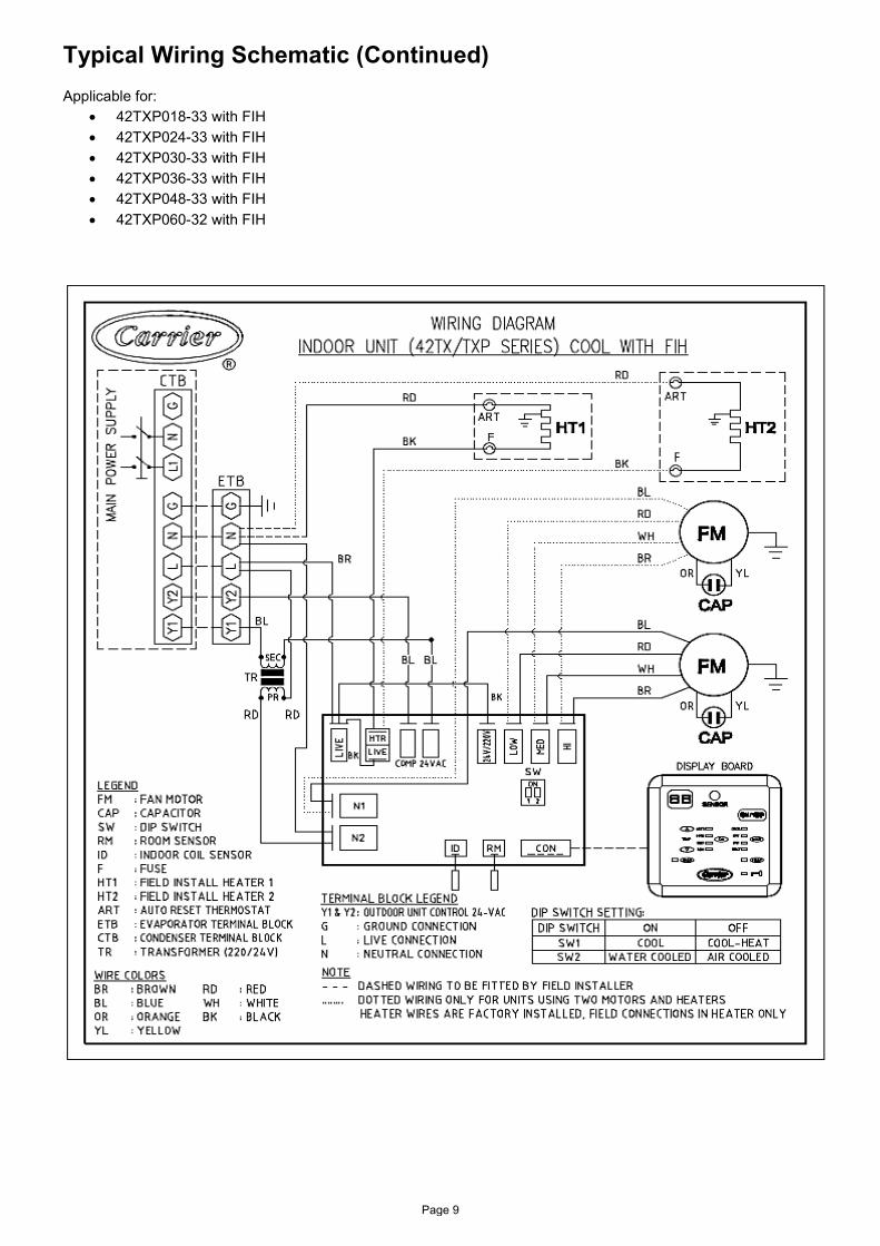
Typical Wiring Schematic (Continued) Applicable for:
• 42TXP018-33 with FIH • 42TXP024-33 with FIH • 42TXP030-33 with FIH • 42TXP036-33 with FIH • 42TXP048-33 with FIH • 42TXP060-32 with FIH
Page 9

Typical Wiring Schematic (Continued) Applicable for:
• 42TXP060-33 with FIH
Page 10

Tot Sen Tot Sen Tot Sen Tot Sen Tot Sen Tot Sen
72.0 21.7 10.8 1.3 20.8 10.5 1.5 19.8 10.1 1.6 18.2 9.4 1.8 16.7 8.8 2.0 15.9 8.5 2.1
66.2 19.7 13.5 1.4 18.8 13.1 1.5 17.4 12.5 1.7 15.9 11.8 1.8 14.4 11.2 2.0 13.6 10.8 2.1
62.0 18.0 15.3 1.4 17.1 14.9 1.5 16.2 14.4 1.6 14.3 13.5 1.8 12.9 12.7 2.0 12.2 12.2 2.0
57.0 16.8 16.8 1.4 16.1 16.1 1.5 15.4 15.4 1.6 13.9 15.4 1.8 12.8 12.8 2.0 12.2 12.2 2.0
72.0 22.4 11.7 1.3 21.5 11.3 1.5 20.5 11.0 1.6 19.0 10.4 1.8 17.4 9.8 2.0 16.5 9.5 2.1
66.2 20.5 15.1 1.3 19.5 14.6 1.5 18.1 14.0 1.6 16.6 13.4 1.8 15.1 12.7 2.0 14.3 12.4 2.1
62.0 19.1 17.4 1.3 18.2 16.9 1.5 16.9 16.3 1.7 15.4 15.4 1.8 14.2 14.2 2.0 13.6 13.6 2.1
57.0 18.4 18.4 1.4 17.7 17.7 1.5 16.7 16.7 1.7 15.4 15.4 1.8 14.2 14.2 2.0 13.6 13.6 2.1
72.0 22.9 12.5 1.3 22.0 12.1 1.5 21.0 11.7 1.6 19.5 11.2 1.8 17.8 10.6 2.0 17.0 10.3 2.1
66.2 21.1 16.5 1.3 20.0 16.0 1.5 19.0 15.5 1.6 17.2 14.8 1.8 15.6 14.1 2.0 14.8 13.8 2.1
62.0 19.9 19.2 1.4 18.9 18.7 1.5 17.7 17.7 1.6 16.4 16.4 1.8 15.1 15.1 2.0 14.5 14.5 2.1
57.0 19.7 19.7 1.4 18.9 18.9 1.5 17.7 17.7 1.6 16.4 16.4 1.8 15.1 15.1 2.0 14.5 14.5 2.1
72.0 28.8 14.3 1.8 27.6 13.8 2.0 26.3 13.2 2.2 24.9 12.7 2.4 23.3 12.0 2.6 22.3 11.7 2.7
66.2 26.0 17.7 1.8 24.8 17.1 2.0 23.5 16.5 2.2 22.2 15.9 2.4 20.2 15.0 2.6 19.3 14.6 2.7
62.0 23.8 19.9 1.8 22.6 19.3 2.0 21.4 18.7 2.1 20.2 18.1 2.3 18.1 17.0 2.5 17.1 16.5 2.6
57.0 22.0 22.0 1.8 21.1 21.1 1.9 20.1 20.1 2.1 19.2 20.1 2.3 17.6 17.6 2.5 16.8 16.8 2.6
72.0 29.8 15.2 1.8 28.5 14.7 2.0 27.1 14.2 2.2 25.6 13.6 2.4 24.0 13.0 2.6 23.2 12.6 2.7
66.2 27.1 19.3 1.8 25.7 18.7 2.0 24.4 18.1 2.2 23.0 17.5 2.4 21.1 16.7 2.6 20.1 16.2 2.7
62.0 25.0 22.1 1.8 23.8 21.4 2.0 22.5 20.8 2.2 21.2 20.2 2.4 19.2 19.1 2.6 18.4 18.4 2.7
57.0 23.8 23.8 1.8 22.8 22.8 2.0 21.8 21.8 2.1 20.8 20.8 2.4 19.2 19.2 2.6 18.4 18.4 2.7
72.0 30.4 16.0 1.8 29.1 15.5 2.0 27.7 15.0 2.2 26.2 14.4 2.4 24.5 13.8 2.6 23.6 13.4 2.7
66.2 27.8 20.8 1.8 26.4 20.1 2.0 25.0 19.6 2.2 23.6 18.9 2.4 21.9 18.2 2.6 20.7 17.7 2.7
62.0 25.9 24.1 1.8 24.7 23.4 2.0 23.3 22.7 2.2 22.0 22.0 2.4 20.4 20.4 2.6 19.6 19.6 2.7
57.0 25.3 25.3 1.8 24.3 24.3 2.0 23.2 23.2 2.2 22.0 22.0 2.4 20.4 20.4 2.6 19.6 19.6 2.7
72.0 36.1 18.0 2.2 34.4 17.3 2.4 32.7 16.6 2.7 30.9 15.9 2.9 28.6 15.0 3.2 27.3 14.5 3.3
66.2 32.7 22.4 2.2 31.3 21.7 2.5 29.6 20.9 2.7 27.4 19.9 2.9 24.8 18.8 3.2 23.4 18.2 3.3
62.0 29.9 25.3 2.2 28.5 24.6 2.4 27.1 23.9 2.7 24.7 22.7 2.9 22.3 21.5 3.1 21.1 20.9 3.3
57.0 28.2 28.2 2.2 27.1 27.1 2.4 25.9 25.9 2.7 24.0 25.9 2.9 22.1 22.1 3.1 21.1 21.1 3.3
72.0 36.9 18.8 2.2 35.1 18.0 2.4 33.3 17.3 2.7 31.6 16.6 2.9 29.3 15.8 3.2 28.0 15.3 3.3
66.2 33.7 23.8 2.2 32.1 23.1 2.5 30.3 22.2 2.7 28.2 21.3 2.9 25.6 20.2 3.2 24.1 19.6 3.3
62.0 30.9 27.1 2.2 29.5 26.4 2.4 28.1 25.7 2.7 25.7 24.5 2.9 23.3 23.3 3.1 22.3 22.3 3.3
57.0 29.7 29.7 2.2 28.5 28.5 2.4 27.3 27.3 2.7 25.4 25.4 2.9 23.3 23.3 3.1 22.3 22.3 3.3
72.0 37.7 19.8 2.2 35.9 19.0 2.4 34.1 18.3 2.7 32.2 17.5 2.9 30.1 16.9 3.2 28.8 16.4 3.3
66.2 34.6 25.7 2.2 32.9 24.8 2.5 31.0 23.9 2.7 29.0 23.2 2.9 26.4 22.2 3.2 25.1 21.6 3.3
62.0 32.2 29.7 2.2 30.7 29.0 2.5 29.2 28.2 2.7 27.0 27.0 2.9 24.9 24.9 3.2 23.8 23.8 3.3
57.0 31.5 31.5 2.2 30.3 30.3 2.5 29.0 29.0 2.7 27.0 27.0 2.9 24.9 24.9 3.2 22.3 22.3 3.3
1. kW* — Total System Power Input2. Ewb — Entering Wet-Bulb3. SHC — Sensible Heat Capacity (1000 Btuh) Gross4. Bold, Italics, Underlined - Standard Ratings5. Formulas:
a) Leaving db = Entering - Sensible Heat Cap / (1.09 x CFM)b) Leaving wb = wb corresponding to air leaving coil (hwb)c) hwb Leaving = hwb entering - total cap(Btuh)/(4.5 X CFM)
6. Direct interpolation is permissible. Do not extrapolate.
Condenser Air Entering Deg. F
30
700
800
950
120
Cap. MBHkW*
Evaporator Air 95 105
Cap. MBHkW*
Cap. MBHkW*
Cap. MBH
NomCap.
Mbtuh
400
500
600
18
CFM
Notes:
Detailed Performance DataMatching 38P with 42TXP
115
Cap. MBHkW*kW*EWB
75 85
Cap. MBH
24
kW*
500
600
700
Page 11

Tot Sen Tot Sen Tot Sen Tot Sen Tot Sen Tot Sen
72.0 40.1 20.1 2.3 38.2 19.4 2.6 36.3 18.6 3.0 33.6 17.5 3.3 30.7 16.4 3.7 29.1 15.8 3.9
66.2 36.4 24.1 2.3 34.7 23.4 2.6 32.7 22.5 3.0 29.6 21.1 3.3 26.6 19.8 3.7 25.1 19.2 3.9
62.0 32.7 27.9 2.3 31.0 27.1 2.6 28.7 25.9 2.9 25.8 24.4 3.3 23.1 22.8 3.6 21.7 21.7 3.8
57.0 30.0 30.0 2.3 28.8 28.8 2.6 26.9 26.9 2.9 24.8 24.8 3.2 22.8 22.8 3.6 21.7 21.7 3.8
72.0 41.4 21.4 2.3 39.4 20.5 2.6 37.5 19.7 3.0 34.9 18.8 3.3 31.9 17.7 3.7 30.3 17.1 3.9
66.2 37.9 26.1 2.3 36.1 25.3 2.6 34.1 24.5 3.0 30.8 23.1 3.3 27.7 21.8 3.7 26.1 21.1 3.9
62.0 34.0 30.5 2.3 32.3 29.6 2.6 30.0 28.4 2.9 27.0 26.6 3.3 24.5 24.5 3.6 23.4 23.4 3.8
57.0 32.1 32.1 2.3 30.8 30.8 2.6 29.0 29.0 2.9 26.7 26.7 3.3 24.5 24.5 3.6 23.4 23.4 3.8
72.0 42.3 22.4 2.3 40.3 21.6 2.6 38.3 20.8 3.0 35.9 20.0 3.4 32.8 18.9 3.7 31.1 18.3 4.0
66.2 38.9 27.9 2.3 37.0 27.0 2.6 35.0 26.1 3.0 31.7 25.0 3.3 28.5 23.6 3.7 26.9 22.9 3.9
62.0 35.1 32.9 2.3 33.3 31.9 2.6 31.2 30.6 3.0 28.3 28.3 3.3 26.0 26.0 3.7 24.8 24.8 3.9
57.0 33.9 33.9 2.3 32.5 32.5 2.6 30.7 30.7 3.0 28.3 30.7 3.3 26.0 26.0 3.7 24.8 24.8 3.9
72.0 52.0 52.0 3.1 49.8 25.1 3.5 47.0 23.8 3.9 43.8 22.4 4.3 40.4 21.0 4.8 38.6 20.5 5.0
66.2 48.3 26.0 3.1 45.7 30.0 3.5 42.6 28.5 3.9 39.5 27.1 4.3 36.1 25.4 4.8 34.2 25.0 5.0
62.0 44.5 33.3 3.1 41.3 34.7 3.4 38.0 32.8 3.8 34.7 31.1 4.2 31.3 29.0 4.6 29.4 28.5 4.9
57.0 40.6 40.6 3.1 37.9 37.9 3.4 35.5 35.5 3.8 33.1 35.5 4.2 30.5 30.5 4.6 29.2 29.2 4.9
72.0 53.5 53.5 3.1 51.2 26.4 3.5 48.5 25.2 3.9 45.1 23.8 4.3 41.6 22.4 4.8 39.7 22.0 5.0
66.2 49.7 27.9 3.1 47.3 32.3 3.5 44.1 30.7 3.9 40.9 29.3 4.3 37.3 27.7 4.8 35.4 27.4 5.0
62.0 46.0 36.5 3.1 43.1 37.9 3.5 39.7 36.0 3.8 36.4 34.1 4.3 32.9 32.0 4.7 31.5 31.5 4.9
57.0 43.4 43.4 3.1 40.8 40.8 3.4 38.2 38.2 3.8 35.6 35.6 4.2 32.9 32.9 4.7 31.5 31.5 4.9
72.0 54.4 42.3 3.1 52.0 27.3 3.5 49.3 26.1 3.9 46.0 24.8 4.3 42.3 23.4 4.8 40.4 23.0 5.0
66.2 50.6 29.3 3.1 48.4 33.9 3.5 45.0 32.0 3.9 41.7 30.9 4.3 38.1 29.2 4.8 36.1 29.0 5.0
62.0 46.8 38.7 3.1 44.0 39.9 3.5 40.7 38.2 3.9 37.5 36.2 4.3 34.4 34.4 4.7 32.9 32.9 5.0
57.0 45.0 45.0 3.1 42.6 42.6 3.5 39.9 39.9 3.9 37.3 37.3 4.3 34.5 34.5 4.7 33.0 33.0 5.0
1. kW* — Total System Power Input2. Ewb — Entering Wet-Bulb3. SHC — Sensible Heat Capacity (1000 Btuh) Gross4. Bold, Italics, Underlined - Standard Ratings5. Formulas:
a) Leaving db = Entering - Sensible Heat Cap / (1.09 x CFM)b) Leaving wb = wb corresponding to air leaving coil (hwb)c) hwb Leaving = hwb entering - total cap(Btuh)/(4.5 X CFM)
6. Direct interpolation is permissible. Do not extrapolate.
Detailed Performance Data (Continued)Matching 38P with 42TXP
NomCap.
Mbtuh
Evaporator Air 75 85 95 105 115
Condenser Air Entering Deg. F
120
CFM EWBCap. MBH
kW* kW*Cap. MBH
kW*Cap. MBH
kW*
36
800
950
1150
Cap. MBHCap. MBHkW*
Cap. MBHkW*
Notes:
48
1050
1250
1400
Page 12
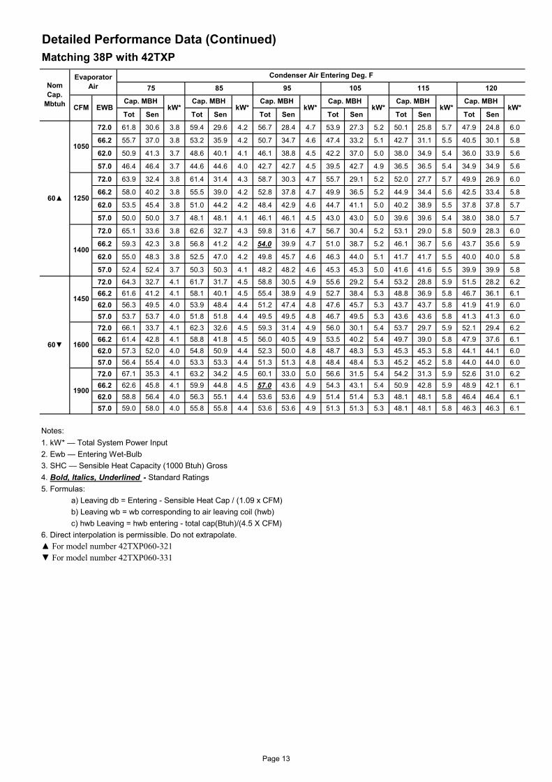
Tot Sen Tot Sen Tot Sen Tot Sen Tot Sen Tot Sen
72.0 61.8 30.6 3.8 59.4 29.6 4.2 56.7 28.4 4.7 53.9 27.3 5.2 50.1 25.8 5.7 47.9 24.8 6.0
66.2 55.7 37.0 3.8 53.2 35.9 4.2 50.7 34.7 4.6 47.4 33.2 5.1 42.7 31.1 5.5 40.5 30.1 5.8
62.0 50.9 41.3 3.7 48.6 40.1 4.1 46.1 38.8 4.5 42.2 37.0 5.0 38.0 34.9 5.4 36.0 33.9 5.6
57.0 46.4 46.4 3.7 44.6 44.6 4.0 42.7 42.7 4.5 39.5 42.7 4.9 36.5 36.5 5.4 34.9 34.9 5.6
72.0 63.9 32.4 3.8 61.4 31.4 4.3 58.7 30.3 4.7 55.7 29.1 5.2 52.0 27.7 5.7 49.9 26.9 6.0
66.2 58.0 40.2 3.8 55.5 39.0 4.2 52.8 37.8 4.7 49.9 36.5 5.2 44.9 34.4 5.6 42.5 33.4 5.8
62.0 53.5 45.4 3.8 51.0 44.2 4.2 48.4 42.9 4.6 44.7 41.1 5.0 40.2 38.9 5.5 37.8 37.8 5.7
57.0 50.0 50.0 3.7 48.1 48.1 4.1 46.1 46.1 4.5 43.0 43.0 5.0 39.6 39.6 5.4 38.0 38.0 5.7
72.0 65.1 33.6 3.8 62.6 32.7 4.3 59.8 31.6 4.7 56.7 30.4 5.2 53.1 29.0 5.8 50.9 28.3 6.0
66.2 59.3 42.3 3.8 56.8 41.2 4.2 54.0 39.9 4.7 51.0 38.7 5.2 46.1 36.7 5.6 43.7 35.6 5.9
62.0 55.0 48.3 3.8 52.5 47.0 4.2 49.8 45.7 4.6 46.3 44.0 5.1 41.7 41.7 5.5 40.0 40.0 5.8
57.0 52.4 52.4 3.7 50.3 50.3 4.1 48.2 48.2 4.6 45.3 45.3 5.0 41.6 41.6 5.5 39.9 39.9 5.8
72.0 64.3 32.7 4.1 61.7 31.7 4.5 58.8 30.5 4.9 55.6 29.2 5.4 53.2 28.8 5.9 51.5 28.2 6.266.2 61.6 41.2 4.1 58.1 40.1 4.5 55.4 38.9 4.9 52.7 38.4 5.3 48.8 36.9 5.8 46.7 36.1 6.162.0 56.3 49.5 4.0 53.9 48.4 4.4 51.2 47.4 4.8 47.6 45.7 5.3 43.7 43.7 5.8 41.9 41.9 6.057.0 53.7 53.7 4.0 51.8 51.8 4.4 49.5 49.5 4.8 46.7 49.5 5.3 43.6 43.6 5.8 41.3 41.3 6.072.0 66.1 33.7 4.1 62.3 32.6 4.5 59.3 31.4 4.9 56.0 30.1 5.4 53.7 29.7 5.9 52.1 29.4 6.266.2 61.4 42.8 4.1 58.8 41.8 4.5 56.0 40.5 4.9 53.5 40.2 5.4 49.7 39.0 5.8 47.9 37.6 6.162.0 57.3 52.0 4.0 54.8 50.9 4.4 52.3 50.0 4.8 48.7 48.3 5.3 45.3 45.3 5.8 44.1 44.1 6.057.0 56.4 55.4 4.0 53.3 53.3 4.4 51.3 51.3 4.8 48.4 48.4 5.3 45.2 45.2 5.8 44.0 44.0 6.072.0 67.1 35.3 4.1 63.2 34.2 4.5 60.1 33.0 5.0 56.6 31.5 5.4 54.2 31.3 5.9 52.6 31.0 6.266.2 62.6 45.8 4.1 59.9 44.8 4.5 57.0 43.6 4.9 54.3 43.1 5.4 50.9 42.8 5.9 48.9 42.1 6.162.0 58.8 56.4 4.0 56.3 55.1 4.4 53.6 53.6 4.9 51.4 51.4 5.3 48.1 48.1 5.8 46.4 46.4 6.157.0 59.0 58.0 4.0 55.8 55.8 4.4 53.6 53.6 4.9 51.3 51.3 5.3 48.1 48.1 5.8 46.3 46.3 6.1
1. kW* — Total System Power Input2. Ewb — Entering Wet-Bulb3. SHC — Sensible Heat Capacity (1000 Btuh) Gross4. Bold, Italics, Underlined - Standard Ratings5. Formulas:
a) Leaving db = Entering - Sensible Heat Cap / (1.09 x CFM)b) Leaving wb = wb corresponding to air leaving coil (hwb)c) hwb Leaving = hwb entering - total cap(Btuh)/(4.5 X CFM)
6. Direct interpolation is permissible. Do not extrapolate.
60▼
1900
▲ For model number 42TXP060-321▼ For model number 42TXP060-331
Notes:
1450
1600
60▲
1050
1250
1400
kW*CFM EWBCap. MBH
kW*Cap. MBH
kW*Cap. MBH
kW*Cap. MBH
Detailed Performance Data (Continued)Matching 38P with 42TXP
NomCap.
Mbtuh
Evaporator Air
Condenser Air Entering Deg. F
75 85 95 105 115
Cap. MBHkW*
Cap. MBHkW*
120
Page 13
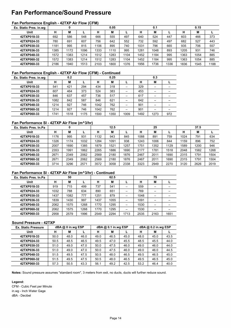
Fan Performance/Sound Pressure
Ex. Static Pres. in.wgUnit H M L H M L H M L H M L
42TXP018-33 692 586 548 666 555 497 640 524 447 603 466 37342TXP024-33 780 691 607 756 642 552 732 592 497 682 527 44342TXP030-33 1181 995 815 1106 895 740 1031 796 665 935 706 55742TXP036-33 1385 1172 1096 1333 1110 995 1281 1048 893 1205 931 74642TXP048-33 1572 1383 1214 1512 1283 1104 1452 1184 995 1363 1054 88542TXP060-32 1572 1383 1214 1512 1283 1104 1452 1184 995 1363 1054 88542TXP060-33 2186 1940 1513 2103 1800 1376 1956 1736 1336 1836 1545 1188
Ex. Static Pres. in.wgUnit H M L H M L H M L
42TXP018-33 541 421 294 434 318 – 329 – –42TXP024-33 607 464 373 524 383 – 453 – –42TXP030-33 846 637 457 736 517 – 617 – –42TXP036-33 1082 842 587 846 621 – 642 – –42TXP048-33 1214 927 746 1042 762 – 901 – –42TXP060-32 1214 927 746 1042 762 – 901 – –42TXP060-33 1741 1518 1175 1500 1350 1009 1492 1273 972
Ex. Static Pres. In.PaUnit H M L H M L H M L H M L
42TXP018-33 1176 995 931 1132 943 845 1088 891 759 1024 791 63442TXP024-33 1326 1174 1032 1284 1091 938 1243 1006 844 1159 896 75242TXP030-33 2007 1690 1385 1879 1521 1257 1751 1352 1129 1589 1200 94642TXP036-33 2353 1991 1862 2265 1886 1690 2177 1781 1518 2048 1582 126842TXP048-33 2671 2349 2062 2569 2180 1876 2467 2011 1690 2315 1791 150442TXP060-32 2671 2349 2062 2569 2180 1876 2467 2011 1690 2315 1791 150442TXP060-33 3714 3296 2571 3572 3058 2338 3323 2949 2270 3120 2626 2019
Ex. Static Pres. In.PaUnit H M L H M L H M L
42TXP018-33 919 715 499 737 541 – 559 – –42TXP024-33 1032 788 634 890 651 – 769 – –42TXP030-33 1437 1082 777 1251 879 – 1048 – –42TXP036-33 1839 1430 997 1437 1055 – 1091 – –42TXP048-33 2062 1575 1268 1770 1295 – 1530 – –42TXP060-32 2062 1575 1268 1770 1295 – 1530 – –42TXP060-33 2958 2579 1996 2549 2294 1713 2535 2163 1651
Ex. Static PressureUnit H M L H M L H M L
42TXP018-33 50.0 48.0 46.0 49.0 46.5 45.0 48.0 45.0 43.542TXP024-33 50.5 48.5 46.5 49.5 47.0 45.5 48.5 45.5 44.042TXP030-33 51.0 49.0 47.0 50.0 47.5 46.0 49.0 46.0 44.042TXP036-33 51.0 49.0 47.0 50.0 47.5 46.0 49.0 46.0 44.542TXP048-33 51.5 49.5 47.5 50.5 48.0 46.5 49.5 46.5 45.042TXP060-32 51.5 49.5 47.5 50.5 48.0 46.5 49.5 46.5 45.042TXP060-33 57.3 50.5 43.3 56.1 49.2 42.5 53.2 46.4 40.0
Notes: Sound pressure assumes "standard room", 3 meters from exit, no ducts, ducts will further reduce sound.
Legend:CFM - Cubic Feet per Minutein.wg - Inch Water GagedBA - Decibel
50 62.5Fan Performance SI - 42TXP Air Flow (m^3/hr) - Continued
75
dBA @ 0 in.wg ESP dBA @ 0.1 in.wg ESP dBA @ 0.2 in.wg ESPSound Pressure - 42TXP
37.5Fan Performance SI - 42TXP Air Flow (m^3/hr)
Fan Performance English - 42TXP Air Flow (CFM)
0.2 0.25 0.3Fan Performance English - 42TXP Air Flow (CFM) - Continued
0 0.05 0.1 0.15
0 12.5 25
Page 14

Controller For Ducted Fan Coil Units Features: The controller is used to control air cooled ducted split unit, supports the following functions: - Modes: Cool, Dry, Fan, Heat - Indoor fan speed: Auto, High, Medium, Low - Sleep mode - Compressor protections:
Comp 3 minutes restart protection Indoor coil anti-freeze Room sensor and indoor coil sensor failure monitoring
- Non volatile memory – keep system settings - Programmable On/Off timer - Random restart to minimize voltage dip during compressor first cut in cycle upon power up. Hardware Setting: A 2 way DIP switch is used to configure:
Error Code: If multiple faults happen at the same time, the corresponding error code will be shown one after another
Split System Description 1) On/Off Key: If you press this key, the system will begin operation, Press the key again, and operation stops. (You can hear a receiving beep). If you press this key immediately after turning off the system, the compressor will not operate for 3 minutes to prevent overloading. 2) Operation Mode Selection Key: Toggles the operation mode: Cool, Dry, Heat, or Fan only
3) Fan Speed Selection Key: Toggles the fan speed: Auto, High, Medium, or Low, Note: Fan key is invalid in Dry mode. 4) Temperature Up Key: By pressing Temperature up Key, the setting temperature increases by 1ºC with each press. 5) Temperature Down Key: By pressing temperature down key, the setting temperature decreases by 1ºC with each press. If you set the desired room temperature, then system will maintain the room temperature as set. Upon setting the desired room temperature the system will maintain the room temperature
DIP Switch On Off SW1 Cool Cool-Heat SW2 Water System DX System
Fault Error code Room sensor fault E1 Indoor coil sensor fault E2 Comp fault E4
“COOL” Led Lights on when selecting COOL mode. “DRY” Led Lights on when selecting DRY mode. “HEAT” Led Lights on when selecting Heat mode. “FAN” Led Lights on when selecting FAN mode.
Wired Room Controller (Standard)
Notes: The wired room controller is mounted on the wall and can control all system functions without wireless remote control.
Fig - 8 System Room Controllers Fig – 7 Split System Setup
Page 15
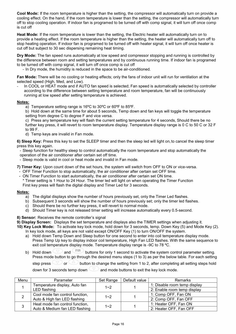
Cool Mode: If the room temperature is higher than the setting, the compressor will automatically turn on provide a cooling effect. On the hand, if the room temperature is lower than the setting, the compressor will automatically turn off to stop cooling operation. If indoor fan is programed to be turned off with comp signal, it will turn off once comp is cut off
Heat Mode: If the room temperature is lower than the setting, the Electric heater will automatically turn on to provide a heating effect. If the room temperature is higher than the setting, the heater will automatically turn off to stop heating operation. If indoor fan is programed to be turned off with heater signal, it will turn off once heater is cut off but subject to 30 sec dispersing remaining heat timing.
Dry Mode: The fan speed runs automatically at low speed and compressor stopping and running is controlled by the difference between room and setting temperatures and by continuous running time. If indoor fan is programed to be turned off with comp signal, it will turn off once comp is cut off
- In Dry mode, the humidity is reduced in the space to be air-conditioned. Fan Mode: There will be no cooling or heating effects; only the fans of indoor unit will run for ventilation at the selected speed (High, Med, and Low). - In COOL or HEAT mode and if AUTO fan speed is selected; Fan speed is automatically selected by controller
according to the difference between setting temperature and room temperature, fan will be continuously running at low speed after setting temperature is achieved.
Notes: a) Temperature setting range is 16ºC to 30ºC or 60ºF to 85ºF. b) Hold down at the same time for about 5 seconds, Temp down and fan keys will toggle the temperature setting from degree C to degree F and vice versa. c) Press any temperature key will flash the current setting temperature for 4 seconds, Should there be no further key press, it will revert to room temperature display. Temperature display range is 0 C to 50 C or 32 F to 99 F. d) Temp keys are invalid in Fan mode.
6) Sleep Key: Press this key to set the SLEEP timer and then the sleep led will light on, to cancel the sleep timer press this key again.
- Sleep function for healthy sleep to control automatically the room temperature and stop automatically the operation of the air conditioner after certain set off time. - Sleep mode is valid in cool or heat mode and invalid in Fan mode.
7) Timer Key: Upon count down of the set hours, the system will switch from OFF to ON or vice-versa. - OFF Timer Function to stop automatically, the air conditioner after certain set OFF time. - ON Timer Function to start automatically, the air conditioner after certain set ON time. * Timer setting is 1 Hour to 24 Hour. The timer led will light on when operating the Timer Function First key press will flash the digital display and Timer Led for 3 seconds.
Notes: a) The digital displays show the number of hours previously set, only the Timer Led flashes. b) Subsequent 3 seconds will show the number of hours previously set; only the timer led flashes. c) Should there be no further key press, it will revert to normal mode. d) Should Timer key is not released timer setting will increase automatically every 0.5-second.
8) Sensor: Receives the remote controller’s signal 9) Display Screen: Displays the set temperature and displays also the TIMER settings when adjusting it. 10) Key Lock Mode: To activate key lock mode, hold down for 3 seconds, temp. Down Key (5) and Mode Key (2).
In key lock mode, all keys are not valid except ON/OFF Key (1) to turn ON/OFF the system. a) Hold down Temp Down and Sleep button for one second to enter into coil temperature display mode.
Press Temp Up key to display indoor coil temperature, High Fan LED flashes. With the same sequence to exit coil temperature display mode. Temperature display range is -9C to 78 ºC.
b) Hold down and FAN buttons for only 1 second to activate the system control parameter setting. Press mode button to go through the desired menu steps (1 to 3) as per the below table. For each setting step press or button to change the setting from 1 to 2, after completing all setting steps hold down for 3 seconds temp down and mode buttons to exit the key lock mode.
Menu Parameter Set Range Default value Remarks
1 Temperature display, Auto fan LED flashing 1~2 1 1: Disable room temp display
2: Enable room temp display
2 Cool mode fan control function, Auto & High fan LED flashing 1~2 1 1: Comp OFF, Fan ON
2: Comp OFF, Fan OFF
3 Heat mode fan control function, Auto & Medium fan LED flashing 1~2 1 1: Heater OFF, Fan ON
2: Heater OFF, Fan OFF
Page 16

42TX
/M
X
Application Data
REMOTE CONTROL
FEMALE SWEAT CONNECTIONS
AT SERVICE VALVES
CONTROL BOARD
FIELD SUPPLIED TYPE L REFRIGERANT
TUBING
FIELD SUPPLIED FILTER DRIER
FIELD SUPPLIED FUSED DISCONNECT
AND WIRING PER NEC
FIELD SUPPLIED 24 V CONTROL
WIRING
FIELD SUPPLIED WEATHERPROOF
FUSED DISCONNECT AND WIRING PER NEC
FIELD SUPPLIED CONDENSATE
DRAIN LINE TO OPEN DRAIN
NOTES:
1. All piping must follow standard refrigerant piping techniques.
2. All wiring must comply with the applicable local and national codes.
3. Wiring and piping shown are general points-of-connection guides only and are not intended for a special installation. 4. Insulate condensate line if run above a conditioned space.
Page 17

Options and Accessories Electric Heater Option (Factory Supplied - Field Installed Option)
A single heater element having capacity of 2.0 and 2.5 kW or two heater elements with a combined capacity of 4.0 kW can be factory installed (Option); the electric heater is open type with thermal protection and fuse for more safety. Heater capacities are available as shown in the following table:
Models Heaters No ; Watts/Heaters Total Heating Capacity kW 42TXP018-33 1 ; 2000 2 42TXP024-33 1 ; 2500 2.5 42TXP030-33
2 ; 2000 4 42TXP036-33 42TXP048-33 42TXP060-32 42TXP060-33
Connection Side Option
Standard coil connection and electric box position is Right Hand facing air flow direction while the optional position is Left Hand facing the air flow for both coil connection and electric box. Customers can order this option directly from the factory also units are designed to be field exchangeable if needed in the field.
Control Board Wire Extension
Standard wire length for control board is 15m optional extensions are available to enlarge the wire up to 30 m. if extension are required, please contact your local Carrier dealer.
UV-C Ready (Factory Supplied - Field Installed Option)
Unit is UV-C Ready for easy installation, UV-C is factory supplied for field installation with field exchangeable connections available for size 30-60.
Page 18

Guide Specifications Cooling Only/Electric Heat Fan Coil Unit HVAC Guide Specifications Size Range: 1.5 to 5 Nominal Tons General System Description The fan coil unit is designed for under ceiling installation, electrically controlled cooling and heating (option). Unit shall be horizontal installation. Standard unit shall include washable permanent aluminum filter. Unit shall be designed for medium external static pressure up to 0.3 inch water. Quality Assurance
A. Unit shall be rated in accordance with SASO 2682/2007. B. Unit shall be designed in accordance with ISO 9001:2008, and shall be manufactured in a facility registered
by ISO 9001:2008. Products
A. The unit shall be factory assembled single piece cooling unit, with optional electric heat.
B. Unit cabinet shall be constructed of galvanized steel. The unit shall be insulated with polyester urethane insulation that is 1/2 inch thickness & 24 kg/m^3 density, Unit cabinet panels shall be single skin
C. Unit shall have a permanent washable aluminum filter. Filter shall be flame retardant and easy accessible through an access panel.
D. Units shall have external drain pan with ½ inch insulation, the drain pane shall be galvanized steel coated with polyester powder for extra protection.
E. The unit fan wheel shall be directly connected to the motor. The fan wheel shall be dynamically balanced with double inlet forward curved type blower wheel.
F. Unit coil shall have aluminum fins mechanically bonded to seamless smooth copper tubes 3/8 inch with all
joints brazed. Unit coil shall be accessible for cleaning.
G. The coil connection shall be sweat type; it shall be RH/LH exchangeable.
H. The unit fan motor shall have permanently lubricated sleeve bearing and 3 speeds, the motor shall have internal overload protection and B class insulation.
I. Unit shall have a wired control board with a built-in thermostat to be installed in the air-conditioned area
and it shall have the following Features: i. Control Modes – Cool, Dry, Fan, Heat, Auto Cool-Heat and Sleep mode. ii. Compressor protections – 3 minutes restart protection. iii. Indoor coil anti-freeze protection. iv. Failure monitoring for room sensor and indoor coil sensor. v. Nonvolatile memory – keep system settings. vi. Programmable On/Off timer. vii. Random Restart Time Delay – to minimize voltage dip during compressor first cut in cycle
upon power up for multiple units operation.
J. Unit shall have a wireless remote to control all the functions of the control board at a distance.
K. All electric parts shall be easy accessible for service.
L. Unit control board shall be 230V/1Ph.
Page 19

Manufacturer reserves the rights to discontinue or change at any time, specifications or designs without notice and without incurring any obligations. Supersedes Version: 42TXP-PDC03 Catalog Number: 42TXP-PDC04Effective Date: 21-04-2015 Phase: 60Hz
Page 20
Related Documents