TEİAŞ-MYD/2005-022.1 420 kV BREAKER TECHNICAL SPECIFICATIONS The original version of this technical specification has been prepared in Turkish and in case of any inconsistency between English and Turkish, the Turkish language shall prevail. PREPARATION : JULY 2005 REVISION-1 : JANUARY 2020

Welcome message from author
This document is posted to help you gain knowledge. Please leave a comment to let me know what you think about it! Share it to your friends and learn new things together.
Transcript
TEİAŞ-MYD/2005-022.1
420 kV BREAKER TECHNICAL SPECIFICATIONS
The original version of this technical specification has been prepared in Turkish and in case of any inconsistency between English and Turkish, the Turkish language shall prevail.
PREPARATION : JULY 2005
REVISION-1 : JANUARY 2020
TEİAŞ
TEİAŞ-MYD/2005-022.1 i 420 kV Breaker
Technical Specifications
420 kV BREAKER TECHNICAL SPECIFICATIONS 1. GENERAL ...............................................................................................................1
1.1. Subject and Scope ............................................................................................ 1
1.2. Standards .......................................................................................................... 1 1.3. Operating Conditions ........................................................................................ 4 1.4. Incompliance with Warranties and Deviations ................................................... 5
2. TECHNICAL CHARACTERISTICS .........................................................................5 2.1. Type .................................................................................................................. 5
2.2. Electrical Characteristics ................................................................................... 5 2.3. Special Conditions ............................................................................................ 6 2.4. Required Breaker Types ................................................................................... 7 2.5. Inductive Current Switching .............................................................................. 8 2.6. Structural Characteristics .................................................................................. 8
2.6.1. General ...................................................................................................... 8 2.6.2. Gas and Gas System ................................................................................ 9
2.6.3. Label ........................................................................................................ 10 2.6.4. Insulators ................................................................................................. 10 2.6.5. HV Terminals ........................................................................................... 13 2.6.6. Operation Mechanism ............................................................................. 13
2.6.7. Control Circuits ........................................................................................ 14 2.6.8. Opening-Closing Counters ...................................................................... 15
2.6.9. Position Indicator and Signal ................................................................... 15 2.6.10. Auxiliary Contacts .................................................................................. 15 2.6.11. Control Cabinet and Cable Installation .................................................. 16
2.6.12. Overpressure Safety Device .................................................................. 17 2.7. Seismic Adequacy Conditions ......................................................................... 17
2.8. Precautions Against Corrosion ........................................................................ 18 2.8.1. General .................................................................................................... 18 2.8.2. Dyeing ..................................................................................................... 18
2.8.3. Galvanizing .............................................................................................. 19 2.9. Assembly ........................................................................................................ 19
3. TESTS ................................................................................................................... 19
3.1. Type Tests ...................................................................................................... 19 3.2. Routine Tests .................................................................................................. 21 3.3. Field Tests ...................................................................................................... 21 3.4. Sampling ......................................................................................................... 21
4. MATTERS ON TESTS AND ACCEPTANCE CRITERIA ...................................... 21
4.1. Type Tests ...................................................................................................... 21 4.2. Routine Tests .................................................................................................. 23 4.3. Acceptance Tests ............................................................................................ 23 4.4. Field Tests ...................................................................................................... 23 4.5. Acceptance Criteria ......................................................................................... 24
4.6. Acceptance Procedure .................................................................................... 24 ANNEX-1: LIST OF WARRANTED CHARACTERISTICS ....................................... 26
FOR 420 kV BREAKER (TYPE L1) .......................................................................... 26 ANNEX-2: LIST OF WARRANTED CHARACTERISTICS ....................................... 32 FOR 420 kV BREAKER (TYPE L2) .......................................................................... 32 ANNEX-3: LIST OF WARRANTED CHARACTERISTICS ....................................... 38 FOR 420 kV BREAKER (TYPE L3) .......................................................................... 38 ANNEX-4: LIST OF WARRANTED CHARACTERISTICS ....................................... 44

TEİAŞ
TEİAŞ-MYD/2005-022.1 ii 420 kV Breaker
Technical Specifications
FOR 420 kV BREAKER (TYPE L4) .......................................................................... 44
ANNEX -5: FLAT TYPE TERMINAL DETAILS FOR 420 kV BREAKER ................ 50 ANNEX-6: LIST OF DEVIATIONS FOR 420 kV BREAKER..................................... 51
TEİAŞ
TEİAŞ-MYD/2005-022.1 1 420 kV Breaker
Technical Specifications
420 kV BREAKER TECHNICAL SPECIFICATIONS
1. GENERAL
1.1. Subject and Scope
These technical specifications contain the technical characteristics of 420 kV, three-phase, outdoor and “live tank” type breakers that will be purchased for use in the switching plants included in the transmission system.
Unless otherwise specified in the Technical Specifications and their annexes, the breakers shall be three-pole and shall be supplied as a complete unit together with their operation mechanism and all auxiliary equipment and materials indicated in the specifications.
The types and technical characteristics of the breakers to be supplied are given in the List of Warranted Characteristics given in the attachment of the technical specifications.
In the following sections of the technical specifications, “420 kV Breaker” shall be referred to as only the “Breaker” and the “420 kV Breaker Technical Specifications” shall be referred to only as the “Technical Specifications”.
1.2. Standards
Unless otherwise specified, the design, manufacture and tests of the breakers included in the scope of these technical specifications shall be performed taking into consideration the latest editions of the following standards and/or documents.
Standard Number Standard Name
(Turkish /English) TSE Standard
No. International Standard No.
TS EN ISO 9001
ISO 9001 Quality Management Systems - Requirements
Quality management systems - Requirements
TS EN ISO 14001
ISO 14001
Environmental Management Systems – Requirements With Guidance For Use
Environmental Management Systems – Requirements With Guidance For Use
TS EN 62271-100
IEC 62271-100
High-voltage switchgear and controlgear -- Part 100: Alternating-current circuit-breakers
High-voltage switchgear and controlgear -- Part 100: Alternating-current circuit-breakers
TS EN 62271-1 IEC 62271-1
High-voltage switchgear and controlgear - Part 1: Common specifications
High-voltage switchgear and controlgear - Part 1: Common specifications
TS EN 62271-110
IEC 62271-110
High-voltage switchgear and controlgear - Part 110: Inductive load switching
High-voltage switchgear and controlgear - Part 110: Inductive load switching
IEC 62271-306
High-voltage switchgear and controlgear - Part 306: Guide to IEC 62271-100, IEC 62271-1 and other IEC standards related to alternating current circuit-breakers
TEİAŞ
TEİAŞ-MYD/2005-022.1 2 420 kV Breaker
Technical Specifications
Standard Number Standard Name
(Turkish /English) TSE Standard
No. International Standard No.
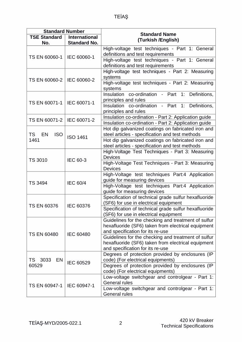
TS EN 60060-1 IEC 60060-1
High-voltage test techniques - Part 1: General definitions and test requirements
High-voltage test techniques - Part 1: General definitions and test requirements
TS EN 60060-2 IEC 60060-2
High-voltage test techniques - Part 2: Measuring systems
High-voltage test techniques - Part 2: Measuring systems
TS EN 60071-1 IEC 60071-1
Insulation co-ordination - Part 1: Definitions, principles and rules
Insulation co-ordination - Part 1: Definitions, principles and rules
TS EN 60071-2 IEC 60071-2 Insulation co-ordination - Part 2: Application guide
Insulation co-ordination - Part 2: Application guide
TS EN ISO 1461
ISO 1461
Hot dip galvanized coatings on fabricated iron and steel articles - specification and test methods
Hot dip galvanized coatings on fabricated iron and steel articles - specification and test methods
TS 3010 IEC 60-3
High-Voltage Test Techniques - Part 3: Measuring Devices
High-Voltage Test Techniques - Part 3: Measuring Devices
TS 3494 IEC 60/4
High-Voltage test techniques Part:4 Application guide for measuring devices
High-Voltage test techniques Part:4 Application guide for measuring devices
TS EN 60376 IEC 60376
Specification of technical grade sulfur hexafluoride (SF6) for use in electrical equipment
Specification of technical grade sulfur hexafluoride (SF6) for use in electrical equipment
TS EN 60480 IEC 60480
Guidelines for the checking and treatment of sulfur hexafluoride (SF6) taken from electrical equipment and specification for its re-use
Guidelines for the checking and treatment of sulfur hexafluoride (SF6) taken from electrical equipment and specification for its re-use
TS 3033 EN 60529
IEC 60529
Degrees of protection provided by enclosures (IP code) (For electrical equipments)
Degrees of protection provided by enclosures (IP code) (For electrical equipments)
TS EN 60947-1 IEC 60947-1
Low-voltage switchgear and controlgear - Part 1: General rules
Low-voltage switchgear and controlgear - Part 1: General rules
TEİAŞ
TEİAŞ-MYD/2005-022.1 3 420 kV Breaker
Technical Specifications
Standard Number Standard Name
(Turkish /English) TSE Standard
No. International Standard No.
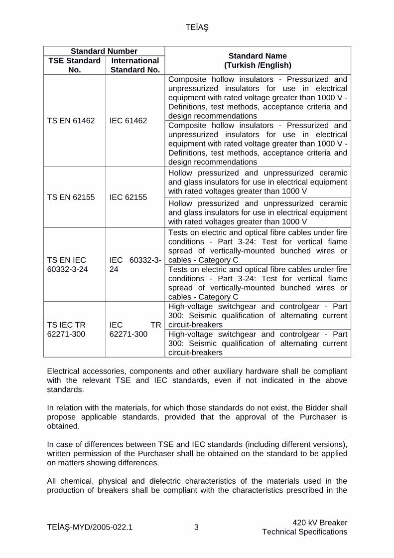
TS EN 61462 IEC 61462
Composite hollow insulators - Pressurized and unpressurized insulators for use in electrical equipment with rated voltage greater than 1000 V - Definitions, test methods, acceptance criteria and design recommendations
Composite hollow insulators - Pressurized and unpressurized insulators for use in electrical equipment with rated voltage greater than 1000 V - Definitions, test methods, acceptance criteria and design recommendations
TS EN 62155 IEC 62155
Hollow pressurized and unpressurized ceramic and glass insulators for use in electrical equipment with rated voltages greater than 1000 V
Hollow pressurized and unpressurized ceramic and glass insulators for use in electrical equipment with rated voltages greater than 1000 V
TS EN IEC 60332-3-24
IEC 60332-3-24
Tests on electric and optical fibre cables under fire conditions - Part 3-24: Test for vertical flame spread of vertically-mounted bunched wires or cables - Category C
Tests on electric and optical fibre cables under fire conditions - Part 3-24: Test for vertical flame spread of vertically-mounted bunched wires or cables - Category C
TS IEC TR 62271-300
IEC TR 62271-300
High-voltage switchgear and controlgear - Part 300: Seismic qualification of alternating current circuit-breakers
High-voltage switchgear and controlgear - Part 300: Seismic qualification of alternating current circuit-breakers
Electrical accessories, components and other auxiliary hardware shall be compliant with the relevant TSE and IEC standards, even if not indicated in the above standards. In relation with the materials, for which those standards do not exist, the Bidder shall propose applicable standards, provided that the approval of the Purchaser is obtained. In case of differences between TSE and IEC standards (including different versions), written permission of the Purchaser shall be obtained on the standard to be applied on matters showing differences. All chemical, physical and dielectric characteristics of the materials used in the production of breakers shall be compliant with the characteristics prescribed in the
TEİAŞ
TEİAŞ-MYD/2005-022.1 4 420 kV Breaker
Technical Specifications
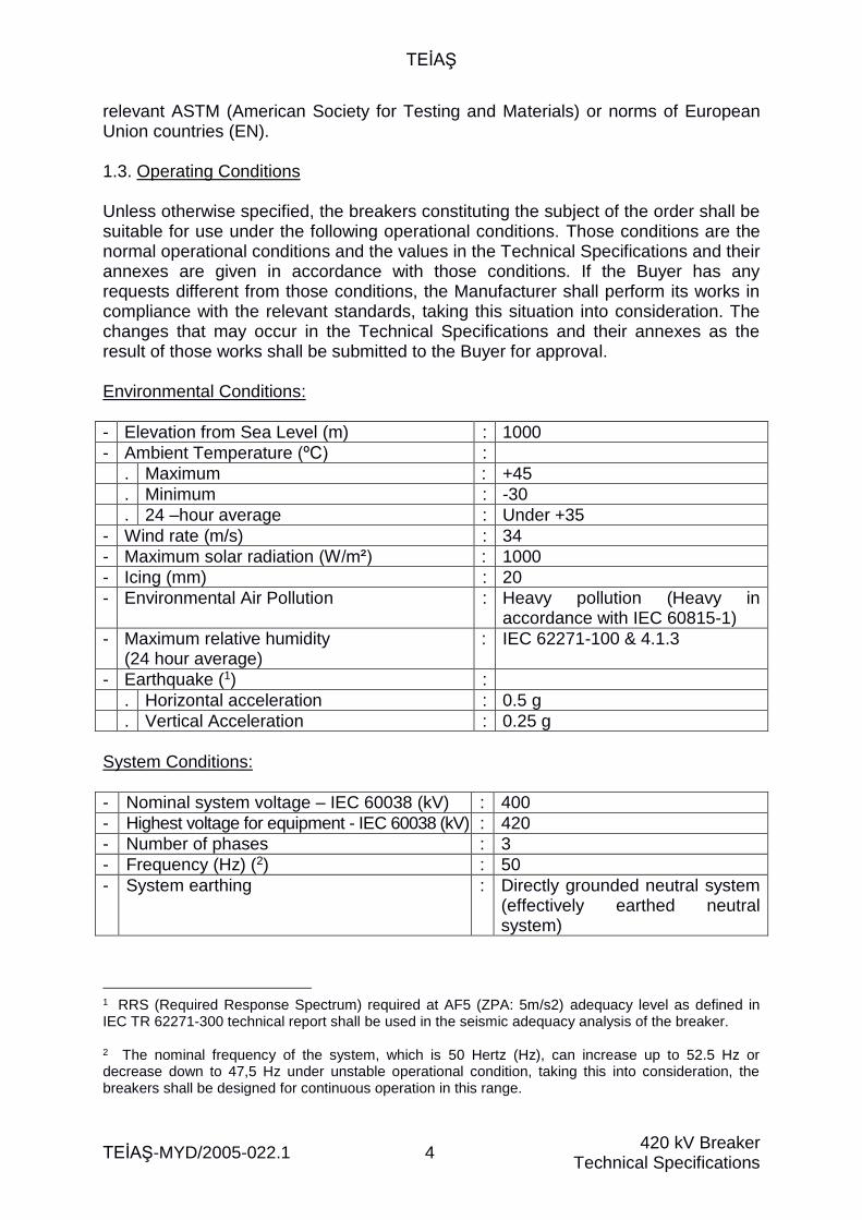
relevant ASTM (American Society for Testing and Materials) or norms of European Union countries (EN). 1.3. Operating Conditions Unless otherwise specified, the breakers constituting the subject of the order shall be suitable for use under the following operational conditions. Those conditions are the normal operational conditions and the values in the Technical Specifications and their annexes are given in accordance with those conditions. If the Buyer has any requests different from those conditions, the Manufacturer shall perform its works in compliance with the relevant standards, taking this situation into consideration. The changes that may occur in the Technical Specifications and their annexes as the result of those works shall be submitted to the Buyer for approval. Environmental Conditions:
- Elevation from Sea Level (m) : 1000
- Ambient Temperature (ºC) :
. Maximum : +45
. Minimum : -30
. 24 –hour average : Under +35
- Wind rate (m/s) : 34
- Maximum solar radiation (W/m²) : 1000
- Icing (mm) : 20
- Environmental Air Pollution : Heavy pollution (Heavy in accordance with IEC 60815-1)
- Maximum relative humidity (24 hour average)
: IEC 62271-100 & 4.1.3
- Earthquake (1) :
. Horizontal acceleration : 0.5 g
. Vertical Acceleration : 0.25 g
System Conditions:
- Nominal system voltage – IEC 60038 (kV) : 400
- Highest voltage for equipment - IEC 60038 (kV) : 420
- Number of phases : 3
- Frequency (Hz) (2) : 50
- System earthing : Directly grounded neutral system (effectively earthed neutral system)
1 RRS (Required Response Spectrum) required at AF5 (ZPA: 5m/s2) adequacy level as defined in IEC TR 62271-300 technical report shall be used in the seismic adequacy analysis of the breaker. 2 The nominal frequency of the system, which is 50 Hertz (Hz), can increase up to 52.5 Hz or decrease down to 47,5 Hz under unstable operational condition, taking this into consideration, the breakers shall be designed for continuous operation in this range.
TEİAŞ
TEİAŞ-MYD/2005-022.1 5 420 kV Breaker
Technical Specifications
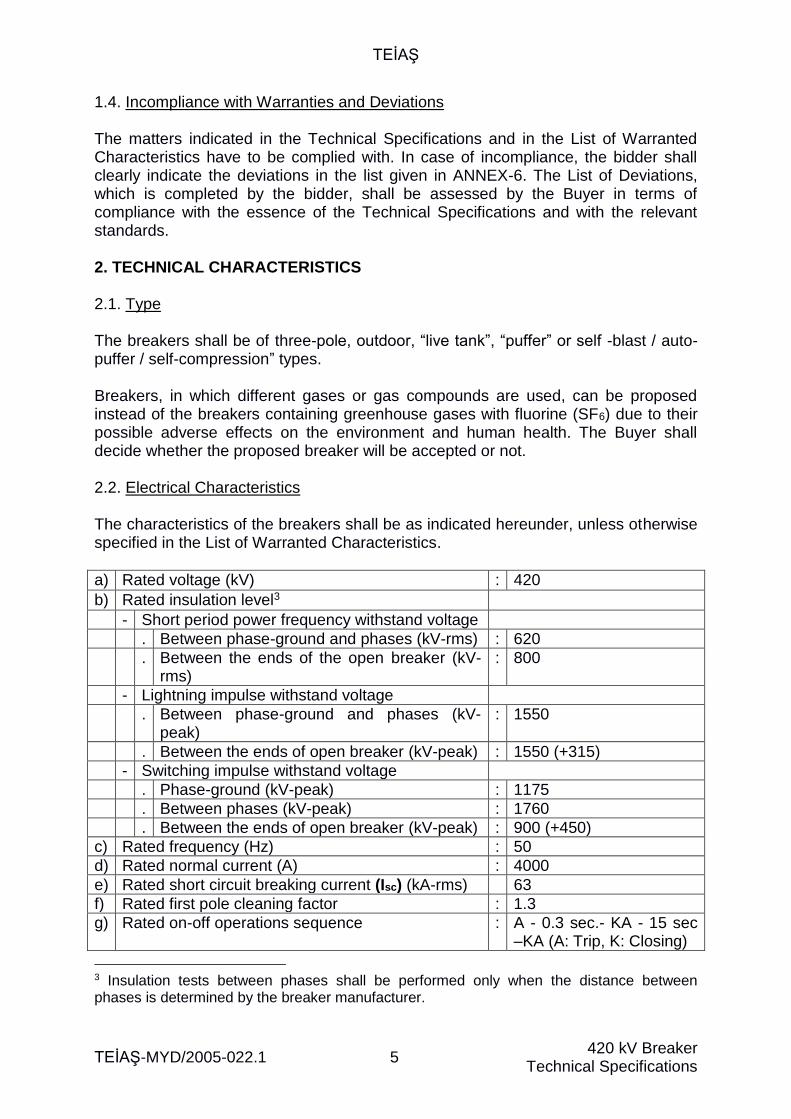
1.4. Incompliance with Warranties and Deviations The matters indicated in the Technical Specifications and in the List of Warranted Characteristics have to be complied with. In case of incompliance, the bidder shall clearly indicate the deviations in the list given in ANNEX-6. The List of Deviations, which is completed by the bidder, shall be assessed by the Buyer in terms of compliance with the essence of the Technical Specifications and with the relevant standards. 2. TECHNICAL CHARACTERISTICS 2.1. Type The breakers shall be of three-pole, outdoor, “live tank”, “puffer” or self -blast / auto-puffer / self-compression” types. Breakers, in which different gases or gas compounds are used, can be proposed instead of the breakers containing greenhouse gases with fluorine (SF6) due to their possible adverse effects on the environment and human health. The Buyer shall decide whether the proposed breaker will be accepted or not. 2.2. Electrical Characteristics The characteristics of the breakers shall be as indicated hereunder, unless otherwise specified in the List of Warranted Characteristics.
a) Rated voltage (kV) : 420
b) Rated insulation level3
- Short period power frequency withstand voltage
. Between phase-ground and phases (kV-rms) : 620
. Between the ends of the open breaker (kV-rms)
: 800
- Lightning impulse withstand voltage
. Between phase-ground and phases (kV-peak)
: 1550
. Between the ends of open breaker (kV-peak) : 1550 (+315)
- Switching impulse withstand voltage
. Phase-ground (kV-peak) : 1175
. Between phases (kV-peak) : 1760
. Between the ends of open breaker (kV-peak) : 900 (+450)
c) Rated frequency (Hz) : 50
d) Rated normal current (A) : 4000
e) Rated short circuit breaking current (Isc) (kA-rms) 63
f) Rated first pole cleaning factor : 1.3
g) Rated on-off operations sequence : A - 0.3 sec.- KA - 15 sec –KA (A: Trip, K: Closing)
3 Insulation tests between phases shall be performed only when the distance between phases is determined by the breaker manufacturer.

TEİAŞ
TEİAŞ-MYD/2005-022.1 6 420 kV Breaker
Technical Specifications
h) Maximum break time (msec) (“Break Time”, IEC 62271-100 & 3.7.135)
: 45
i) Maximum Closing Time (msec) (“Closing Time”, IEC 62271-100 & 3.7.136)
110
j) Transient regime pull-up voltage for terminal and out-of-phase failure tests (TRV) (T100, T60, T30, T10, OP1, OP2)
: Values corresponding to 420 kV rated voltage in IEC 62271-100, Table 264
k) Characteristics for short line failures (L90, L75 and L60)
Values corresponding to 420 kV rated voltage in IEC 62271-100, Table 49.
l) Rated short circuit closing current (kA-peak) (time constant in accordance with IEC 62271-100: 45 msec)
: (Isc) x 2.5
m) Rated short time withstand current (kA-rms) : (Isc)
n) Rated peak withstand current (kA-peak) : (Isc) x 2.5
o) Rated duration of short-circuit (second) : 3
p) Mechanical strength class : Class M2
q) Re-strike performance during capacitive current switching
: Class C2
r) Rated capacitive switching currents Values corresponding to 420 kV rated voltage in IEC 62271-100, Table 9
s) Rated out-of-phase breaking current (kA-rms) : (Isc) x 25 %
t) Inductive Load Switching for shunt reactor application
: IEC 62271-110
u) Surface leakage path distance for insulators (mm/kV)
: 25
2.3. Special Conditions
Arc extinguishing/ breaking performance shall be consistent for the entire operation regime from line/ cable charge currents to full short circuit currents. The definitions given in IEC 62271-100 standard shall be taken as basis in the definition of time performance limits requested in the technical specifications, including the maximum breaking time. IEC 62271-100 shall be taken as basis for the characteristics and conditions of the system that are not indicated in the technical specifications. PSCAD software based transient models, which show the stray capacitance values of the breakers, shall be submitted to the Buyer before the delivery of the breakers.
4 The TRV values defined in the List of Warranted Characteristics shall be taken into consideration for L2 type breaker
TEİAŞ
TEİAŞ-MYD/2005-022.1 7 420 kV Breaker
Technical Specifications
2.4. Required Breaker Types
The breakers included in the scope of these specifications shall be used at transformer centers having 400 kV rated voltage, which constitute the transmission system of TEİAŞ. The breakers shall be used in TEİAŞ transmission system as line, transfer, coupling, shunt reactor, transformer/ transformer banks and capacitor bank breakers. For the breaker types that will be supplied together with a controlled switching device, the responsibility for the first assembly and correct operation of the controlled switching device shall belong to the breaker manufacturer. The controlled switching device shall be functional in both tripping and closing operations of the equipment. The following breaker types shall be proposed depending on the place of use: L1 Type Breaker: Place of Use : Serial non-compensated transmission line
shorter than 200 km, Coupling Is closing resistance requested? : No Is Grading capacitor requested? : No5 Is controlled switching device requested?
: No
L2 Type Breaker: Place of Use : Serial compensated transmission line,
transmission line longer than 200 km, Transfer
Is closing resistance requested? : Yes Is grading capacitor requested? : Yes6 Is controlled switching device requested?
: No
L3 Type Breaker: Place of Use : Transformer, Transformer Banks Is closing resistance requested? : No Is grading capacitor requested? : No5
Is controlled switching device requested?
: Yes
5 The expression “No” in relation with grading capacitor use does not show the requirement not to use it, and the design preference of the manufacturer will be accepted about this matter. 6 In case it is proven that the TRV values indicated in the requested column of the list of warranted characteristics for L2 type breakers are obtained without a grading capacitor, it will not be required to use a grading capacitor and it will be left to the preference of the manufacturer.
TEİAŞ
TEİAŞ-MYD/2005-022.1 8 420 kV Breaker
Technical Specifications
L4 Type Breakers: Place of Use : Shunt Reactor, Shunt Capacitor Is closing resistance requested? : No Is grading capacitor requested? : Yes7 Is controlled switching device requested?
: Yes
2.5. Inductive Current Switching L3 and L4 type breakers defined in these specifications will be used for switching the loads of inductive characteristics, which are created by transformers and transformer banks and shunt reactors used in TEİAŞ system. The auto-transformers used in TEİAŞ transmission system have a rated power of 150 MVA, 250 MVA and 450 MVA, their HV and LV windings are star connected and their neutral points are directly grounded. The autotransformer banks are as 150+150 MVA, 150+250 MVA or 250+250 MVA. The breakers to be used for the autotransformers and autotransformer banks shall have the ability to break the no-load current of the autotransformer/ autotransformer bank. The shunt reactors used in TEİAŞ transmission system have a rated power in the range 73 MVAr and 250 MVAr at 420 kV, are three-phase, their winding is star connected and are of neutral directly grounded type. The characteristics of the shunt reactor to be used in switching shall be indicated separately by the Buyer in the list of warranted characteristics. 2.6. Structural Characteristics 2.6.1. General The dimensions of the breaker shall be as follows unless otherwise indicated in the list of warranted characteristics: - Clearance between the axes of adjacent poles 5500 mm, - Clearance between the bottom point of the insulator and the ground minimum
2300 mm, The breakers shall be fixed to a separate concrete foundation for each of their legs and they shall allow easy assembly. The foundation drawings shall be submitted together with the bid.
7 If for the L4 type breakers to be used in shunt switching, the test reports evidencing that the proposed breaker is sufficient for minimum 1000 tripping operations of the shunt reactors, the characteristics of which are indicated in the technical specifications and list of warranted characteristics without the use of controlled switching, then grading capacitor use shall not be compulsory, but shall be the preference of the manufacturer, provided that the approval of the Buyer is obtained.
TEİAŞ
TEİAŞ-MYD/2005-022.1 9 420 kV Breaker
Technical Specifications
There shall be two grounding terminals with compressing screws on each pole of the breakers with a capacity to carry the rated short circuit current of the breaker and it shall be clearly marked with a “Grounding” symbol. The breakers and especially the terminals and steel constructions of their support insulators shall be designed so as to withstand their stationary weight, the responsive forces during their operation, wind loads, static and dynamic forces caused by the lines, tensions and seismic earthquakes without any damage or wrong operation. It shall be possible to easily access the bolts and nuts that must be loosened or disassembled during maintenance and repair using appropriate tools and they shall be appropriately protected against rusting and corrosion. A lifting hook, lifting pad or a similar mechanism with a capacity sufficient to carry a completely assembled breaker/ breaker pole shall be provided to allow easy lifting. All exposed surfaces, chassis, tank, operation mechanism etc. shall be coated so as to be corrosion-resistant. All exposed parts of the breakers shall be resistant against climatic conditions. 2.6.2. Gas and Gas System The characteristics of SF6 gas to be used in the breakers shall be compliant with IEC 60376. The breaker manufacturer shall submit its instructions on the use and charging/ discharging operations of SF6 gas to the Buyer in compliance with IEC TR 62271-303 technical report. Gas leakage shall not exceed %0.5 / year in the breakers. The tightness characteristics of the pressure system and the period between re-charges under normal service conditions shall be indicated by the manufacturer. This period shall be minimum 10 years for maintenance planning. The materials used in manufacturing the breakers shall be suitable for use with the gases in the breaker. Filter system shall be provided for cleaning the polluters such as humidity, particles etc. that are formed in the gas/ gases in the breaker as the result of an arc or any other reason. The gas density for each pole of the breaker shall be continuously checked with a density meter with temperature compensation belonging to the relevant pole. The density meters shall have a “green” region for normal operational pressure, a “yellow” region for alarm and a “red” region for locking and their indicator shall be easily readable in any density range. In case of reduction of gas density, the density meters shall have a contact output at two different stages. It shall give an alarm at the first stage. In the second stage, if the breaker is open, it shall lock the breaker so

TEİAŞ
TEİAŞ-MYD/2005-022.1 10 420 kV Breaker
Technical Specifications
as to prevent closing, and if the breaker is closed, it shall lock the re-closing breakers in closed position and non-re-closing breakers after opening them. The density meters shall be made of non-rusting material and shall be operable at ambient temperature under the envisaged operational conditions. Since the density meters are impacted by the solar rays, design precautions shall be taken to prevent the unnecessary opening – closing operation of the breaker. For this purpose, the density meter shall be in a shading housing so as not to be exposed to direct sunlight. The device shall be assembled at eye level in the cabinet, shall be easily readable without any intervention and in any case, it shall be easily seen from outside. A tap shall be placed on the gas pipe connected to the control device. That tap shall be the same as the one used for charging and shall be used for controlling the pressure with the main meter or for controlling gas humidity. For copper pipe manostate and pole connections, irreversible valves, which open the gas path by pushing each other, shall be provided. 2.6.3. Label A label made of stainless steel or any other corrosion – resistant material shall be provided on the breakers or operational mechanism. The label shall be attached using stainless steel screws so as to be easily visible under normal operation and assembly conditions. The inscriptions shall not deteriorate in time. All inscriptions shall be in Turkish or shall be repeated in Turkish. The highest tested values of the rated current and rated short circuit breaking current of the breaker shall be indicated in the label plate, even if a lower value was indicated in the tender file. The information to be shown on the label plate shall be compliant with IEC 62271-100 (Article 5.10, Table 10) standard. The label plate shall contain the information requested by the Buyer and indicated in the tender file for this purpose as well as the information that are required to be contained on the plate in compliance with the standard; - Order number (shall be given by the Buyer), - Telephone number that will provide uninterrupted service during the warranty period, Final condition of the label plate shall be submitted to the approval of the Buyer. 2.6.4. Insulators The insulators used in the breakers can be porcelain or composite. The insulator requested by the Buyer shall be indicated in the list of warranted characteristics and the manufacturer shall perform delivery in accordance with that request. The relevant section of the technical specifications and standards shall be taken as basis in accordance with the requested insulator type.
TEİAŞ
TEİAŞ-MYD/2005-022.1 11 420 kV Breaker
Technical Specifications
2.6.4.1 Composite insulator The insulators to be used in the breakers shall be made of high-quality composite silicon. The composite silicon insulators shall be composite silicon coated on reinforced fiberglass tube and shall consist of members with metal fittings at the ends. Composite silicon shall be flame-resistant, shall not contain spaces, shall be hydrophobic (water repellant) and shall be resistant against explosion and disintegration. The base polymer material to be used in composite silicon (before the addition of reinforcing filling materials) shall be 100% silicon rubber. The filling materials to be added shall be selected to be suitable for the vibrations and atmospheric and seismic conditions that may occur during operation or short circuit. The insulators shall withstand the forces that will occur both under normal operational conditions and due to the overvoltage that will occur in the system. The insulators shall withstand the forces occurring due to short circuits, earthquakes and vibration and shall be designed and manufactured so as to be suitable for the atmospheric conditions. The insulation parts of the insulators shall be smooth and symmetrical, shall ensure the uniform distribution of the electrical field and shall be designed to minimize radio interference. The insulation sections of the manufactured insulators shall not be subjected to any process after the completion of manufacture, shall be flat and flawless. The flanges, bolts, bolt slots and other metal sections of the insulators shall be fixed on the insulator so as to prevent breaking and loosening in case of temperature variations and mechanical forces. The material to be used for fixing shall be high quality and shall not enter in chemical reactions with metal sections. The minimum surface leakage path length shall be minimum 25 mm/kV unless otherwise specified by the Buyer in the List of Warranted Characteristics
Hollow Insulator Tube
Reinforced fiberglass tube shall be made of fiberglass material with chemical resistance against electrical corrosion, acid corrosion and hydrolysis in order to ensure maximum strength, shall be of E-Glass or ECR-Glass type and it shall be documented that it has those characteristics. Hollow composite silicon insulator tube shall be mechanically and electrically strong, shall not contain spaces, shall be free from foreign materials and shall not contain any manufacturing defects. The manufacturers of materials such as fiberglass, epoxy resin etc. that will be used in tube manufacture and the technical documents of those materials shall be submitted to the Buyer.
TEİAŞ
TEİAŞ-MYD/2005-022.1 12 420 kV Breaker
Technical Specifications
Silicon Body and Leaves
The thickness of the silicon material covering the tube shall not be less than 3.00 mm in any section and shall be tightly bonded to the tube. The strength of the bond between the silicon material and the tube shall be higher than the tearing strength of composite silicon. The profile parameters of silicon leaves shall be in “none” region among the regions indicated in article 9 titled as “Checking of profile parameters” of IEC 60815-3 standard. If the silicon body and leaves are manufactured using injection method in mold, the insulators shall be manufactured in maximum three presses. The technical documents containing the general characteristics and physical and strength- related information of the material to be used in the silicon body and leaves shall be submitted to the Buyer by the Contractor. The silicon body and leaves shall be resistant against flame, environmental impacts, UV rays, infrared rays, external pollution and humidity, shall be hydrophobic and shall keep those properties during their entire operational life. The manufacturers shall take precautions against insulator damage caused by birds and rodents. The clearance, dimensions, slopes and shapes of the leaves shall be compliant with the technical characteristics indicated in the relevant standards, shall ensure the best electrical performance and shall be designed so as not to retain dirt, dust etc. on them. All other housing characteristics shall be compliant with IEC TR 62039.
End Parts
The material to be used in the manufacturing of end parts shall be aluminum type, galvanized steel or corrosion-resistant material having appropriate hardness. Sharp edges and corners shall not be formed in manufacturing the end parts.
Tightness
A permanent tightness system shall be formed between the hollow composite silicon insulator tube and metal end parts so as to prevent leakage of humidity, acid etc. materials and the performance of the tightness system shall be analyzed in the frame of the relevant standards. The tightness system shall ensure maximum protection. The tightness system and its characteristics shall be submitted with drawings and explanations.
Ceramic Insulator
The insulators to be used in the breakers shall be made of high-quality porcelain.
TEİAŞ
TEİAŞ-MYD/2005-022.1 13 420 kV Breaker
Technical Specifications
The ceramic insulation material characteristics of the insulators shall be compliant with class C130 as defined in IEC 60672-3. The porcelain of the insulators shall be high-quality and shall have a homogeneous structure; the surfaces of the insulators exposed to atmosphere shall be glazed with smooth, flawless, brown glaze in an even way. The glaze shall not be impacted by sudden temperature changes and shall be resistant against industrial pollution, ozone, acid, alkalis, salt, dust and other atmospheric conditions. The insulators shall not contain any foreign materials, cracks, shells, air bubbles, scratches, burrs, roughness, spots, stains and similar flaws. The insulators shall be resistant against the forces that will occur due to overvoltage both under normal operational conditions and in the system. The insulators shall be designed and manufactured so as to resist the forces occurring due to short circuits, earthquake and vibration, and atmospheric conditions. The flanges, bolts, bolt slots and other metal sections of insulators shall be fixed on the insulator so as not to allow breaking or loosening due to temperature changes and mechanical forces. The material to be used for fixing shall be high-quality and shall not enter in chemical reaction with metal sections. The minimum surface leakage path distance shall be minimum 25 mm/kV unless otherwise specified. The profile parameters shall be in the “none” region among the regions (none/minor/major) indicated in article 9 titled as “Checking of profile parameters” of IEC 60815-2 standard.
2.6.5. HV Terminals High voltage terminals shall be without corona and shall be of flat type made of aluminum or cylindrical type made of copper or copper alloy as indicated in the List of Warranted Characteristics or in accordance with the drawing in ANNEX-5. Cylindrical type copper terminals shall be dimensioned with minimum 90 mm length and 50 mm diameter and shall be coated with minimum 20 µm thick silver. Aluminum flat type terminals shall have minimum HB 75 hardness. 2.6.6. Operation Mechanism The operation mechanism shall be of spring – operated mechanism type. The breakers shall have an appropriate design for fast re-closing. The breakers shall be trip-free. Dependent operation can be permitted only for maintenance and repair purposes.
TEİAŞ
TEİAŞ-MYD/2005-022.1 14 420 kV Breaker
Technical Specifications
The energy storage capacity of the operation mechanism shall be sufficient for realizing A - K - A (A - 0.3 sec.- KA) series without requiring refreshing. Manual opening – closing mechanism shall be provided for use during maintenance. A mechanism shall be formed for manually setting the closing spring. The instruments – tools to be used for setting the spring shall be kept on the breaker, in a safe and protected section. The operation mechanism shall be provided together with all control and safety equipment. An alarm signal shall be provided while there is no control voltage and that alarm signal shall be shown on the control panel of the breaker. It shall be possible to detect whether the closing spring is set or not with a mechanical indicator on the mechanism box that can be remotely seen. The status indication of the spring shall be supported with “YAY KURULU” and “YAY BOŞTA” Turkish expressions as well as the symbol indication. The mechanism shall be manufactured with a mechanism that prevents over-setting the spring after fully setting the closing spring in order to prevent damage to the mechanism, and information shall be provided on the method and operation of the mechanism. In manufacturing the mechanism, a material similar to stainless steel, brass or gunmetal shall be used wherever necessary to prevent rusting. General design shall be made so as to minimize the impacts and so as to prevent undesired operation due to fault current voltages, vibration or other reasons. Appropriate mechanisms shall be provided for lubrication. All bolts, nuts and rods shall be safely secured to prevent loosening during operation. 2.6.7. Control Circuits A control switch and a selector switch with “Remote – Local – Disabled” positions shall be provided in the control cabinet of the breaker. The following functions shall be performed in accordance with the position of the selector switch: - In remote position, the local control functions shall be blocked on the mechanism
box, and remote opening and closing functions of all poles of the breaker from the control building and with control relays shall be permitted.
- In the local position, the remote opening and closing functions from the control
building shall be blocked, however opening with control relays shall be possible, and opening and closing functions of all poles of the breaker using the local button shall be permitted.
- In the disabled position, all remote and local controls shall be blocked.
TEİAŞ
TEİAŞ-MYD/2005-022.1 15 420 kV Breaker
Technical Specifications
The breakers shall also have an emergency local control mechanism with direct mechanical control to be used only for local maintenance and repair. The emergency opening device shall be labeled and clearly indicated and shall be protected against unintended operation. All breakers shall have out-of-phase protection, for which the starting time can be set, which can be locked during automatic single-phase reclosing, and it shall have contacts for remote notification. The control circuit shall have “anti-pumping” protection. Unless otherwise specified, opening and closing circuits shall be supplied from 110V or 220 VDC system as indicated in the List of Warranted Characteristics. The opening circuit shall be accurately operable under voltages between 70% and 110% of the rated supply voltage. Those values shall be 85% and 110% of the rated voltage for the closing circuit and other auxiliary DC circuits. The spring setting motors shall be supplied with 230 V AC, single phase, 50 Hz voltage. The motors shall be capable of operating correctly under voltages between 85% and 110% of the rated supply voltage. The motors shall have their own thermal protection and signal contacts for remote notification. When an electrical closing impulse with a period > 50 msec is applied on the closing coil, the breaker shall close correctly. 2.6.8. Opening-Closing Counters The counter of the breaker shall increase by 1 when the series K-A (CO) takes place once and shall have a design suitable for showing minimum 9999 series. It shall not be possible to reset the counter. The operation of the counter shall not be affected by vibrations. 2.6.9. Position Indicator and Signal All breakers shall have an easily visible position indicator and signal contacts for the position signal in the control room. The indicators and contacts shall be mechanically excited and preferably connected to the excitation rod of the moving contact. The latest position of the breaker shall be seen on the indicator as position. Position Sign Property Closed position of the breaker
I White letters on red background
Open position of the breaker
O White letters on green background
2.6.10. Auxiliary Contacts The breakers shall have auxiliary contacts that are directly connected to the operation mechanism.
TEİAŞ
TEİAŞ-MYD/2005-022.1 16 420 kV Breaker
Technical Specifications
In addition to the ones required for normal control of the breaker, there shall be 8 open and 8 closed contacts for locking, position indicator, etc. The changeover switches shall not be accepted as 1 open + 1 closed contact. The contacts shall be made of copper coated with minimum 5 micron thick galvanic silver. All auxiliary contacts shall have minimum 10 A DC continuous current carrying capacity and shall not exceed the temperature increase prescribed in IEC 62271-100. 2.6.11. Control Cabinet and Cable Installation The operation mechanism of the breaker, the control switches, auxiliary switches and relevant relays, control cable connections and other auxiliary equipment shall be placed in a control cabinet of IP 55 (IEC 60529) protection class. The control cabinet shall be constructed so as to be accessible from the front and rear, preferably as an independent unit. The control cabinet shall be made of minimum 2 mm thick stainless steel or aluminum material, shall have a strong construction and shall include the support steel structures necessary for assembly on the breaker carrier chassis or on concrete foundations. All partitions shall be accessible through detachable covers or detachable hinged doors. Bolts shall not be used to hold the covers or doors. All holders shall be a part of the cover or door and furthermore, a locking mechanism shall be provided. The cabinets shall be ventilated so as to prevent condensation. There shall be minimum one heater, which shall be continuously switched on against condensation in the cabinet. If the manufacturer has a different proposal, the methods shall be explained in detail. There shall be a lighting lamp in the cabinet, which is controlled with a switch connected to the door. There shall be a socket in the control cabinet, which is fed separately from the lighting and heater circuit. The socket circuit shall be protected with a 16A miniature circuit breaker (MCB). A sufficient number of terminals, to which minimum 2x6 mm² conductors can be connected, which is fire-resistant and non-combustible type, shall be provided. All external connections shall be made on terminals. Terminal blocks shall be assembled on metal rails with spring connection. The rails shall be grounded. Terminals and connection cables shall be marked or nicknamed. A copper grounding bar shall be provided to connect the shields of shielded cables and other equipment requiring grounding in the cabinet. The external connections of each pole shall be brought to the main control cabinet, the connections between the breaker and other equipment shall be made over the terminals in the main control cabinet. Each terminal group shall have minimum 10% spare terminals for future use. A sufficient number of cable entry holes equipped with cable end sleeves and plastic taps shall be provided in the cabinets. Approved control circuit diagram showing various components in the breaker and the cabinet and assembly instructions shall be hung on the cabinet door. The diagram
TEİAŞ
TEİAŞ-MYD/2005-022.1 17 420 kV Breaker
Technical Specifications
and instructions shall be written on a non-fading material that is resistant against operational conditions. A sufficient number of grounding terminals to be connected to the grounding conductor shall be placed on the cabinet. All external electrical connections of the breaker shall be appropriately protected against mechanical forces, dust, etc. The cables used in the control cabinet shall have sufficient cross section (minimum 1,5 mm2 cross section), shall be compliant with IEC 60332-3-24 standard and shall be of minimum Uo/U=0.6/1 kV insulation level. For connections to the equipment, additional cable stretching margin shall be left on hinged chassis. External electrical connections shall be laid in ducts. All cable ends connected to the terminal blocks shall be equipped with sleeves to allow their appropriate selection. It shall be possible to use color cables or self numbered cables. Circuit insulation shall be as follows: - Power frequency withstand voltage : 2 kV rms Secondary cabling connections between phases and connections to common control panel must be made with jacks. 2.6.12. Overpressure Safety Device If the breaker has a ceramic insulator, pressure safety device shall be used against excessive internal pressure. The devices shall be compliant with ISO 4126 standard and shall be calibrated over maximum operational pressure to avoid from wrong operations. 2.7. Seismic Adequacy Conditions The seismic adequacy of the breaker shall be proven through a test in accordance with IEC TR 62271-300 using RRS: Required Response Spectrum at AF5 (ZPA: 5m/s2) adequacy level defined in IEC TR 62271-300 technical report or with dynamic analysis method in accordance with IEEE 693 standard. The seismic adequacy analysis has to be approved by an organization having former references in this area or by a university competent in this area. If the Buyer does not think the approving organization or university is competent in this area, the analysis shall not be accepted. The projects, drawings and materials necessary for the installation of breakers at their place of operation shall be provided by the Contractor.
TEİAŞ
TEİAŞ-MYD/2005-022.1 18 420 kV Breaker
Technical Specifications
2.8. Precautions Against Corrosion 2.8.1. General The materials and methods used in the manufacture of breakers and in cleaning the surfaces shall ensure that the corrosion is minimized. The following precautions shall be taken against corrosion: - Current-carrying parts shall be made of non-ferrous materials. - All surfaces shall be arranged so as not to hold water as much as possible and all
cabinets and boxes shall have drainage holes protected against ingress of insects. - The material to be used in manufacturing shall be chosen and arranged so as not
to cause corrosion. - The aluminum alloys that carry current or that are used as construction members
shall be corrosion-resistant. - Ferrous parts shall be hot dip galvanized or painted. 2.8.2. Dyeing The dyeing operation shall begin just after the preparation of the surfaces to be painted. Following the rust-preventing undercoat, the external surfaces shall be painted with base coat and final coat of dye. The dye shall not have any pores after drying. The final layer shall be resistant against weather conditions and oil and shall be gray (RAL 7032 or RAL 7035). Dye thickness shall be 90±15 microns. The producer shall submit the dyeing method to be applied to the Buyer for approval and shall indicate the thickness of each dye layer. When electrostatic coating method is applied, polyester type dust paints shall be used and coating thickness shall be compliant with the relevant standards. If the producers want to apply the dyeing methods other than the ones indicated hereunder, they shall indicate such method clearly in their bids and shall submit the relevant documents, if any. The qualification of the dye shall be determined in accordance with the thickness of layers and by checking their bonding. Dye thickness shall be measured using a “Dye checking device” at five randomly selected points. The average thickness of each layer shall not be lower than the value indicated by the manufacturer. Total paint thickness shall not be less than the indicated value at any point.
TEİAŞ
TEİAŞ-MYD/2005-022.1 19 420 kV Breaker
Technical Specifications
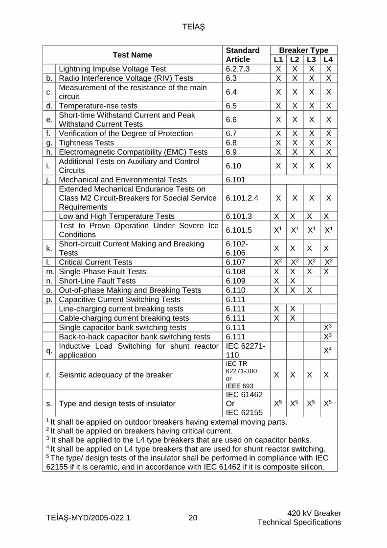
The bonding of dye layers shall be checked using the cross-scraping method in compliance with ISO 2409 at five randomly selected points. The result of the test shall not be worse than class-1 included in this standard. 2.8.3. Galvanizing The galvanizing operation and the tests on galvanized surfaces shall be performed in compliance with ISO 1461 on galvanizing. The average coating thickness shall be as in the tables defined in ISO 1461 in accordance with the thickness of the galvanized surface and the type of material coated. The galvanizing operation shall be performed at a place having ISO 9001 Quality Management System certificate and the reports prepared on the galvanizing operation shall be submitted to the Buyer. Hot dip galvanizing of all metal parts, including the threads of bolts and screw bars, shall be performed after completing the processing, bending, cutting, punching, centering, marking and welding operations and after thoroughly cleaning the surfaces from the rust and oils using sand blasting, chemical cleaning etc. methods. After guiding and thread cleaning of galvanized nuts or after opening threads again, the nuts shall be lubricated using water resistant and rust-preventing oil. Small parts that cannot be dyed and hot dip galvanized shall be electro-galvanized or shall be made of stainless steel. Electro-galvanize thickness shall be minimum 12 microns. 2.9. Assembly Supervision service shall be provided for the assembly, field tests and commissioning of breakers and the relevant price shall be included in the breaker price for each breaker. The user’s manual/manual containing topics such as unloading, storage, assembly, commissioning, disassembly, maintenance, repair and use of breakers, which is prepared in Turkish, shall be submitted to the Purchaser in the form of one hardcopy and one reproducible electronic copy. 3. TESTS All tests indicated hereunder shall be performed in compliance with the relevant TSE and IEC standards. 3.1. Type Tests The type tests indicated in the table shall be applied to the breaker types marked with an (X) across them, in compliance with IEC 62271-100 standard.
Test Name Standard Article
Breaker Type
L1 L2 L3 L4
a. Dielectric tests 6.2
Power Frequency Voltage Tests 6.2.7.1 X X X X
Switching Impulse Voltage Test 6.2.7.2 X X X X
TEİAŞ
TEİAŞ-MYD/2005-022.1 20 420 kV Breaker
Technical Specifications
Test Name Standard Article
Breaker Type
L1 L2 L3 L4
Lightning Impulse Voltage Test 6.2.7.3 X X X X
b. Radio Interference Voltage (RIV) Tests 6.3 X X X X
c. Measurement of the resistance of the main circuit
6.4 X X X X
d. Temperature-rise tests 6.5 X X X X
e. Short-time Withstand Current and Peak Withstand Current Tests
6.6 X X X X
f. Verification of the Degree of Protection 6.7 X X X X
g. Tightness Tests 6.8 X X X X
h. Electromagnetic Compatibility (EMC) Tests 6.9 X X X X
i. Additional Tests on Auxiliary and Control Circuits
6.10 X X X X
j. Mechanical and Environmental Tests 6.101
Extended Mechanical Endurance Tests on Class M2 Circuit-Breakers for Special Service Requirements
6.101.2.4 X X X X
Low and High Temperature Tests 6.101.3 X X X X
Test to Prove Operation Under Severe Ice Conditions
6.101.5 X1 X1 X1 X1
k. Short-circuit Current Making and Breaking Tests
6.102-6.106
X X X X
l. Critical Current Tests 6.107 X2 X2 X2 X2
m. Single-Phase Fault Tests 6.108 X X X X
n. Short-Line Fault Tests 6.109 X X
o. Out-of-phase Making and Breaking Tests 6.110 X X X
p. Capacitive Current Switching Tests 6.111
Line-charging current breaking tests 6.111 X X
Cable-charging current breaking tests 6.111 X X
Single capacitor bank switching tests 6.111 X3
Back-to-back capacitor bank switching tests 6.111 X3
q. Inductive Load Switching for shunt reactor application
IEC 62271-110
X4
r. Seismic adequacy of the breaker
IEC TR 62271-300 or IEEE 693
X X X X
s. Type and design tests of insulator IEC 61462 Or IEC 62155
X5 X5 X5 X5
1 It shall be applied on outdoor breakers having external moving parts. 2 It shall be applied on breakers having critical current. 3 It shall be applied to the L4 type breakers that are used on capacitor banks. 4 It shall be applied on L4 type breakers that are used for shunt reactor switching. 5 The type/ design tests of the insulator shall be performed in compliance with IEC 62155 if it is ceramic, and in accordance with IEC 61462 if it is composite silicon.
TEİAŞ
TEİAŞ-MYD/2005-022.1 21 420 kV Breaker
Technical Specifications
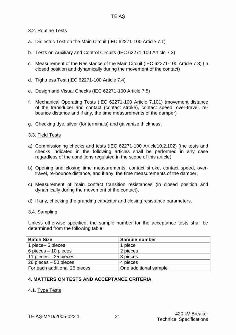
3.2. Routine Tests a. Dielectric Test on the Main Circuit (IEC 62271-100 Article 7.1)
b. Tests on Auxiliary and Control Circuits (IEC 62271-100 Article 7.2)
c. Measurement of the Resistance of the Main Circuit (IEC 62271-100 Article 7.3) (in
closed position and dynamically during the movement of the contact)
d. Tightness Test (IEC 62271-100 Article 7.4)
e. Design and Visual Checks (IEC 62271-100 Article 7.5) f. Mechanical Operating Tests (IEC 62271-100 Article 7.101) (movement distance
of the transducer and contact (contact stroke), contact speed, over-travel, re-bounce distance and if any, the time measurements of the damper)
g. Checking dye, silver (for terminals) and galvanize thickness, 3.3. Field Tests a) Commissioning checks and tests (IEC 62271-100 Article10.2.102) (the tests and
checks indicated in the following articles shall be performed in any case regardless of the conditions regulated in the scope of this article)
b) Opening and closing time measurements, contact stroke, contact speed, over-
travel, re-bounce distance, and if any, the time measurements of the damper, c) Measurement of main contact transition resistances (in closed position and
dynamically during the movement of the contact), d) If any, checking the granding capacitor and closing resistance parameters. 3.4. Sampling Unless otherwise specified, the sample number for the acceptance tests shall be determined from the following table:
Batch Size Sample number
1 piece– 5 pieces 1 piece
6 pieces – 10 pieces 2 pieces
11 pieces – 25 pieces 3 pieces
26 pieces – 50 pieces 4 pieces
For each additional 25 pieces One additional sample
4. MATTERS ON TESTS AND ACCEPTANCE CRITERIA 4.1. Type Tests
TEİAŞ
TEİAŞ-MYD/2005-022.1 22 420 kV Breaker
Technical Specifications
For each type of breaker it proposed, the Bidder/ Contractor shall submit the Buyer the type test reports of the tests indicated under article titled as 3.1 “Type Tests” of the technical specifications in compliance with the standards and conditions indicated in article titled as 1.2 “Standards” of the technical specifications, which are performed by a laboratory accredited by Turkish Accreditation Institution or by the accreditation institutions included in the International Laboratory Accreditation Collaboration Mutual Recognition Agreement. The reports submitted for the following type tests of the breaker; - Short-time Withstand Current and Peak Withstand Current Tests, - Short-circuit current making and breaking tests, - Switching Tests (Capacitive switching, inductive switching, critical current, out-of-
phase, single-phase failure, short line failure etc.) Have to be certificated by one of the laboratories, which are, STL (The Short-Circuit Testing Liaison) members. The reports belonging to such type tests, which are not prepared by one of the STL member laboratories shall be rejected, the repetition of those rejected tests shall be had performed by STL member laboratories and shall be certificated. In the type test reports, introductory information on the sample, which is the subject of the test in accordance with article 6.1.2 of IEC 62271-100 standard and information on the rated values in accordance with article 6.1.3 of the same standard and information for proving compliance with the test articles in the relevant standard shall be provided in the contents or attachment of the report. If the submitted type test reports belong to test/tests performed by the manufacturer’s laboratory, which is an accredited laboratory, those tests will have to be performed under the supervision of the Purchaser. The type test reports submitted to the Buyer shall belong to tests performed on breakers that are produced at the same factory and that are of the same type and properties as the proposed breakers. If the breaker, for which the type test report is submitted, is not exactly the same as the proposed breaker, however if the breaker cell and mechanism are exactly of the same type and characteristics; the submitted type test repots shall be deemed to be sufficient for the proposed breaker, provided that it is expressed that the tested breaker was tested under stricter conditions and that the Buyer approves it. A table containing information on the factory, where the breakers were produced, the type and characteristics of the breaker, to which it belongs, the laboratory that performed the type tests and the date of performance of the tests shall be submitted in Turkish in detail with the necessary explanations. For goods purchase tenders, if the type test reports are not submitted together with the bid, or if the proposed breaker does not have the same characteristics (does not cover them) and/or if those reports are submitted incompletely, the Contractor will be able to submit the type test reports together with the approval documents, and in
TEİAŞ
TEİAŞ-MYD/2005-022.1 23 420 kV Breaker
Technical Specifications
case such submission cannot be made, the type tests shall be performed by an accredited laboratory or a laboratory to be approved by the Directorate under the supervision of the Directorate representatives just before the first acceptance test in the scope of the order, and all relevant expenses shall be borne by the Contractor. For building work tenders, the Contractor shall submit all type test reports together with the approval documents after signing the contract. In case of failure in submitting all type tests, submission of them incompletely or incompatibility of the tests, approval documents shall not be approved before those tests are completed. Furthermore, application cannot be made for acceptance tests before completing the approval operation. 4.2. Routine Tests The tests covered under article 3.2 titled as “Routine Tests” of the Technical specifications shall be applied by the manufacturer on each breaker ordered in the scope of the contract, in accordance with the standards and conditions indicated under article 1.2 titled as “Standards” of the technical specifications and routine test reports shall be submitted to the Buyer before delivery in the form of 2 (two) copies in CD/DVD medium. 4.3. Acceptance Tests The tests covered by article titled as 3.2 “Routine Tests” of the technical specifications shall be applied on samples to be selected in appropriate amount under article 3.4 titled as “Sampling” of the technical specifications, in accordance with the standards and conditions indicated under article titled as 1.2 “Standards” of the technical specifications, under the supervision of TEİAŞ representatives, as acceptance tests for the delivery of each batch of breakers. Acceptance tests shall be performed at the manufacturer’s laboratory or a laboratory to be approved by the Buyer. Routine test reports shall be submitted to the Inspection and Acceptance Commission before starting the acceptance tests. Otherwise, test and acceptance operations shall not be commenced. After the completion of type tests, all of the breakers indicated for each batch indicated in the delivery schedule have to be accepted. In case of completion of the type tests, upon Contractor’s request and confirmation of the Buyer, it shall be possible to perform partial delivery after performing the test and acceptance of breakers in the amount, for which manufacturing is completed. 4.4. Field Tests If the assembly of the breakers, which will be provided in the scope of the order, will be performed by the Contractor, the tests included in Technical Specifications Article 3.3 titled as “Field Tests” shall be performed on each breaker, for which assembly is completed, and if the assembly will be performed by the Buyer, such tests shall be performed on one breaker from each drawing (including assembly in place and commissioning) by the Contractor under the supervision of Buyer’s representatives and the charge of those tests shall be included in the breaker price.
TEİAŞ
TEİAŞ-MYD/2005-022.1 24 420 kV Breaker
Technical Specifications
All of the details related with the tests to be performed shall be submitted by the Contractor and the test equipment necessary for the tests shall be provided by the Contractor. 4.5. Acceptance Criteria a) The calibrations of the devices to be used in the tests shall be performed by an
accredited organization and calibration certificates shall be submitted to the Inspection and Acceptance Commission before commencing the tests.
b) Positive results shall be obtained from all type tests to be performed. In case a negative result is obtained from a type test, the breaker or insulator belonging to the drawing/ type, which had a negative result, shall be rejected. However, upon Contractor’s request and Buyer’s confirmation, the repetition of the tests for the new product, which is produced by making the necessary changes within a reasonable period, can be accepted without any period extension, provided that the discretion will be only the Buyer’s. If those second tests also result negatively, all of the order belonging to the negatively resulted drawing/ type shall be rejected.
c) Positive results shall be obtained from all acceptance tests. In case a negative
result is obtained in any of the acceptance tests, the test/ tests shall be repeated on new samples, which are twice the first samples in number, if not otherwise specified in the relevant standards.
None of the samples selected for the test must be defective. If defective units are detected, the Buyer can reject the entire batch or can request the Contractor to replace the defective units and to perform the relevant tests in compliance with the conditions of the type technical specifications. 4.6. Acceptance Procedure The Buyer or its representative is free in examining and/or testing the breakers in order to verify their compliance with the technical specifications. The Buyer shall provide written information to the Contractor on the identification of any representative assigned for this purpose. Manufacture control and tests can be performed at the manufacturer’s plants, material delivery place or final place of delivery of materials. During manufacture control and tests, any kind of aid and facilitation shall be provided for the inspectors, including the permission to review drawings and production information, without requiring the Buyer to pay any expense. The Contractor shall notify the test schedule to the Buyer after signing the contract. The Contractor shall notify the Buyer on the date of tests minimum 45 (forty five) days before the test for the tests to be performed abroad and minimum 15 (fifteen) days before the tests for the tests to be performed in the country. As the result of the successful tests and inspections, the test reports shall be mutually signed and Shipment Order shall be given by the representatives of the Buyer. The Contractor shall submit 2 (two) copies of mutually signed test report to the representatives of the Buyer. However, the Buyer may inform the Contractor in
TEİAŞ
TEİAŞ-MYD/2005-022.1 25 420 kV Breaker
Technical Specifications
time that it shall not be present at the tests. If the Buyer notifies the Contractor that it shall not participate in the tests, the Contractor shall perform the tests and notify their results to the Buyer. The test reports prepared and signed by the Contractor shall be sent to the Buyer in 3 (three) copies for inspection and approval. If the test reports are approved, the Buyer shall place a Shipment Order for delivery and 1 (one) copy of approved test report shall be sent back to the Contractor. In case it is understood that the examined and tested materials are not compliant with the Type Technical Specifications, the Buyer can reject them. If accepted by the Buyer, the Contractor shall replace the rejected materials with new ones bearing all relevant expenses or shall make the changes to ensure compliance with the Type Technical Specifications. All manufacturing controls, type tests, acceptance tests and field tests to be performed shall be performed under the supervision of the Buyer’s representatives with all relevant expenses being borne by the Contractor.

TEİAŞ
TEİAŞ-MYD/2005-022.1 26 420 kV Breaker (Type L1)
List of Warranted Characteristics
ANNEX-1:
LIST OF WARRANTED CHARACTERISTICS FOR 420 kV BREAKER (TYPE L1)
Order No: ………………………… Drawing No: ………………………… Mtr. Code No of Buyer: …………………………
DEFINITION UNIT REQUESTED WARRANTED
1. Name and origin of the Manufacturer -
2. Type mark of the Manufacturer -
3. Operational Conditions (shall be determined by the Buyer)
- Elevation from sea level (Meter)
- Ambient temperature
Maximum (°C)
Minimum (°C)
24-hour average (°C)
- Wind speed (m/s)
- Maximum solar radiation (W/m²)
- Icing (mm)
- Ambient air pollution (IEC 60815-1) -
- Maximum relative humidity (24-hour average) (IEC 62271-100)
(%)
- Earthquake (See T.S. article 1.3)
Horizontal acceleration (g) 0.5
Vertical acceleration (g) 0.25
4. Applied standards - Indicated in T.S. Article 1.2
5. Number of poles (piece) 3
6. Use Environment (Indoor/ Outdoor) - Outdoor
7. Breaker class
- Mechanical strength class (IEC 62271-
100) - M2
- Capacitive switching class (IEC
62271-100) - C2
8. Breaker cell number for each pole (piece)
9. Arc extinguishing method of the breaker (puffer/self-blast/auto-puffer/self-compression etc.)
-
10. Gas mixture use in the breaker (Yes/No)
- No
11. Mechanism design (1-pole operation/ 3-pole operation)
- 1-pole operation
12. Rated opening-closing operations sequence
A - 0.3 sn. - KA – 15 sn. - KA
TEİAŞ
TEİAŞ-MYD/2005-022.1 27 420 kV Breaker (Type L1)
List of Warranted Characteristics
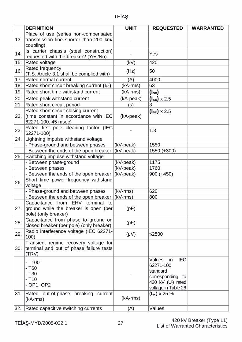
DEFINITION UNIT REQUESTED WARRANTED
13. Place of use (series non-compensated transmission line shorter than 200 km/ coupling)
-
14. Is carrier chassis (steel construction) requested with the breaker? (Yes/No)
- Yes
15. Rated voltage (kV) 420
16. Rated frequency (T.S. Article 3.1 shall be complied with)
(Hz) 50
17. Rated normal current (A) 4000
18. Rated short circuit breaking current (Isc) (kA-rms) 63
19. Rated short time withstand current (kA-rms) (Isc)
20. Rated peak withstand current (kA-peak) (Isc) x 2.5
21. Rated short circuit period (s) 3
22. Rated short circuit closing current (time constant in accordance with IEC 62271-100: 45 msec)
(kA-peak) (Isc) x 2.5
23. Rated first pole cleaning factor (IEC 62271-100)
- 1.3
24. Lightning impulse withstand voltage
- Phase-ground and between phases (kV-peak) 1550
- Between the ends of the open breaker (kV-peak) 1550 (+300)
25. Switching impulse withstand voltage
- Between phase-ground (kV-peak) 1175
- Between phases (kV-peak) 1760
- Between the ends of the open breaker (kV-peak) 900 (+450)
26. Short time power frequency withstand voltage
- Phase-ground and between phases (kV-rms) 620
- Between the ends of the open breaker (kV-rms) 800
27. Capacitance from EHV terminal to ground while the breaker is open (per pole) (only breaker)
(pF)
28. Capacitance from phase to ground on closed breaker (per pole) (only breaker)
(pF)
29. Radio interference voltage (IEC 62271-100)
(µV) ≤2500
30. Transient regime recovery voltage for terminal and out of phase failure tests (TRV)
- T100 - T60 - T30 - T10 - OP1, OP2
-
Values in IEC 62271-100 standard corresponding to 420 kV (Ur) rated voltage in Table 26
31. Rated out-of-phase breaking current (kA-rms) (kA-rms)
(Isc) x 25 %
32. Rated capacitive switching currents (A) Values
TEİAŞ
TEİAŞ-MYD/2005-022.1 28 420 kV Breaker (Type L1)
List of Warranted Characteristics
DEFINITION UNIT REQUESTED WARRANTED
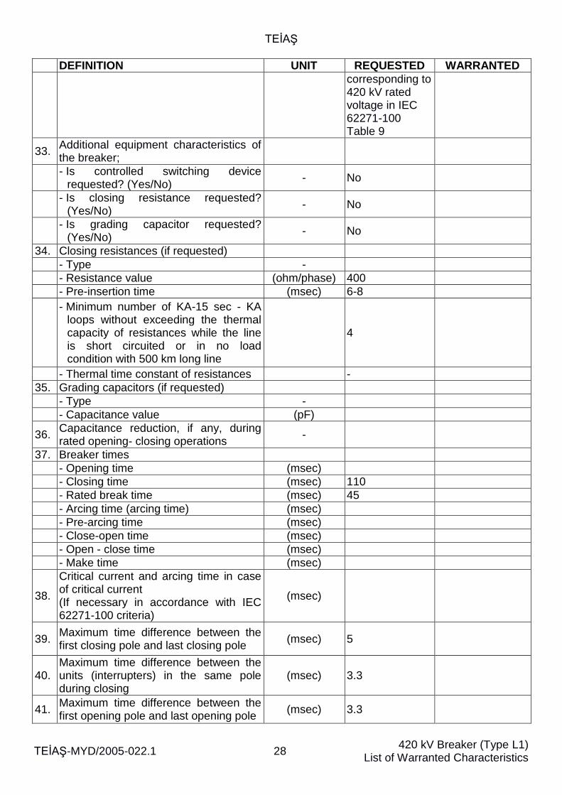
corresponding to 420 kV rated voltage in IEC 62271-100 Table 9
33. Additional equipment characteristics of the breaker;
- Is controlled switching device
requested? (Yes/No) - No
- Is closing resistance requested?
(Yes/No) - No
- Is grading capacitor requested?
(Yes/No) - No
34. Closing resistances (if requested)
- Type -
- Resistance value (ohm/phase) 400
- Pre-insertion time (msec) 6-8
- Minimum number of KA-15 sec - KA loops without exceeding the thermal capacity of resistances while the line is short circuited or in no load condition with 500 km long line
4
- Thermal time constant of resistances -
35. Grading capacitors (if requested)
- Type -
- Capacitance value (pF)
36. Capacitance reduction, if any, during rated opening- closing operations
-
37. Breaker times
- Opening time (msec)
- Closing time (msec) 110
- Rated break time (msec) 45
- Arcing time (arcing time) (msec)
- Pre-arcing time (msec)
- Close-open time (msec)
- Open - close time (msec)
- Make time (msec)
38.
Critical current and arcing time in case of critical current (If necessary in accordance with IEC 62271-100 criteria)
(msec)
39. Maximum time difference between the first closing pole and last closing pole
(msec) 5
40. Maximum time difference between the units (interrupters) in the same pole during closing
(msec) 3.3
41. Maximum time difference between the first opening pole and last opening pole
(msec) 3.3
TEİAŞ
TEİAŞ-MYD/2005-022.1 29 420 kV Breaker (Type L1)
List of Warranted Characteristics
DEFINITION UNIT REQUESTED WARRANTED
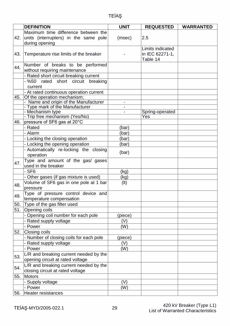
42. Maximum time difference between the units (interrupters) in the same pole during opening
(msec) 2.5
43. Temperature rise limits of the breaker - Limits indicated in IEC 62271-1, Table 14
44. Number of breaks to be performed without requiring maintenance
- Rated short circuit breaking current
- %50 rated short circuit breaking
current
- At rated continuous operation current 45. Of the operation mechanism;
- Name and origin of the Manufacturer - - Type mark of the Manufacturer - - Mechanism type - Spring-operated - Trip free mechanism (Yes/No) Yes
46. pressure of SF6 gas at 20°C
- Rated (bar)
- Alarm (bar)
- Locking the closing operation (bar)
- Locking the opening operation (bar)
- Automatically re-locking the closing
operation (bar)
47. Type and amount of the gas/ gases used in the breaker
- SF6 (kg)
- Other gases (if gas mixture is used) (kg)
48. Volume of SF6 gas in one pole at 1 bar pressure
(lt)
49. Type of pressure control device and temperature compensation
50. Type of the gas filter used
51. Opening coils
- Opening coil number for each pole (piece)
- Rated supply voltage (V)
- Power (W)
52. Closing coils
- Number of closing coils for each pole (piece)
- Rated supply voltage (V)
- Power (W)
53. L/R and breaking current needed by the opening circuit at rated voltage
54. L/R and breaking current needed by the closing circuit at rated voltage
55. Motors
- Supply voltage (V)
- Power (W)
56. Heater resistances
TEİAŞ
TEİAŞ-MYD/2005-022.1 30 420 kV Breaker (Type L1)
List of Warranted Characteristics
DEFINITION UNIT REQUESTED WARRANTED
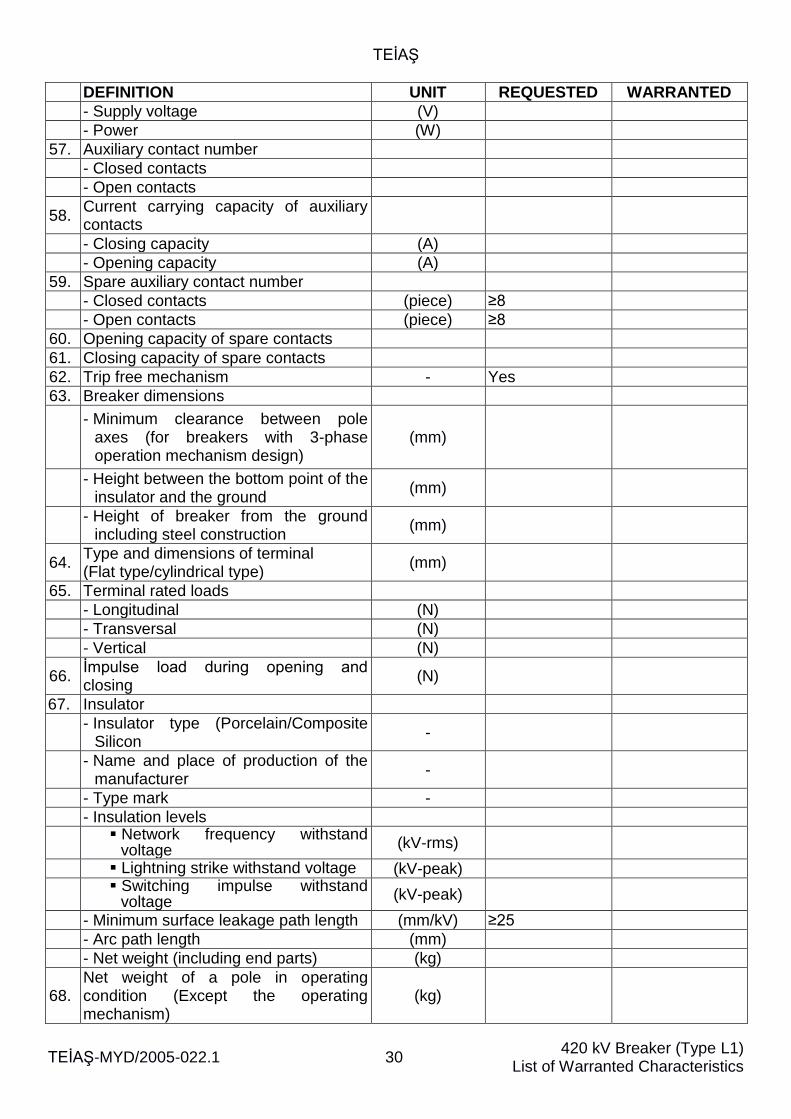
- Supply voltage (V)
- Power (W)
57. Auxiliary contact number
- Closed contacts
- Open contacts
58. Current carrying capacity of auxiliary contacts
- Closing capacity (A)
- Opening capacity (A)
59. Spare auxiliary contact number
- Closed contacts (piece) ≥8
- Open contacts (piece) ≥8
60. Opening capacity of spare contacts
61. Closing capacity of spare contacts
62. Trip free mechanism - Yes
63. Breaker dimensions
- Minimum clearance between pole
axes (for breakers with 3-phase operation mechanism design)
(mm)
- Height between the bottom point of the
insulator and the ground (mm)
- Height of breaker from the ground
including steel construction (mm)
64. Type and dimensions of terminal (Flat type/cylindrical type)
(mm)
65. Terminal rated loads
- Longitudinal (N)
- Transversal (N)
- Vertical (N)
66. İmpulse load during opening and closing
(N)
67. Insulator
- Insulator type (Porcelain/Composite
Silicon -
- Name and place of production of the
manufacturer -
- Type mark -
- Insulation levels
Network frequency withstand
voltage (kV-rms)
Lightning strike withstand voltage (kV-peak)
Switching impulse withstand
voltage (kV-peak)
- Minimum surface leakage path length (mm/kV) ≥25
- Arc path length (mm)
- Net weight (including end parts) (kg)
68. Net weight of a pole in operating condition (Except the operating mechanism)
(kg)
TEİAŞ
TEİAŞ-MYD/2005-022.1 31 420 kV Breaker (Type L1)
List of Warranted Characteristics
DEFINITION UNIT REQUESTED WARRANTED
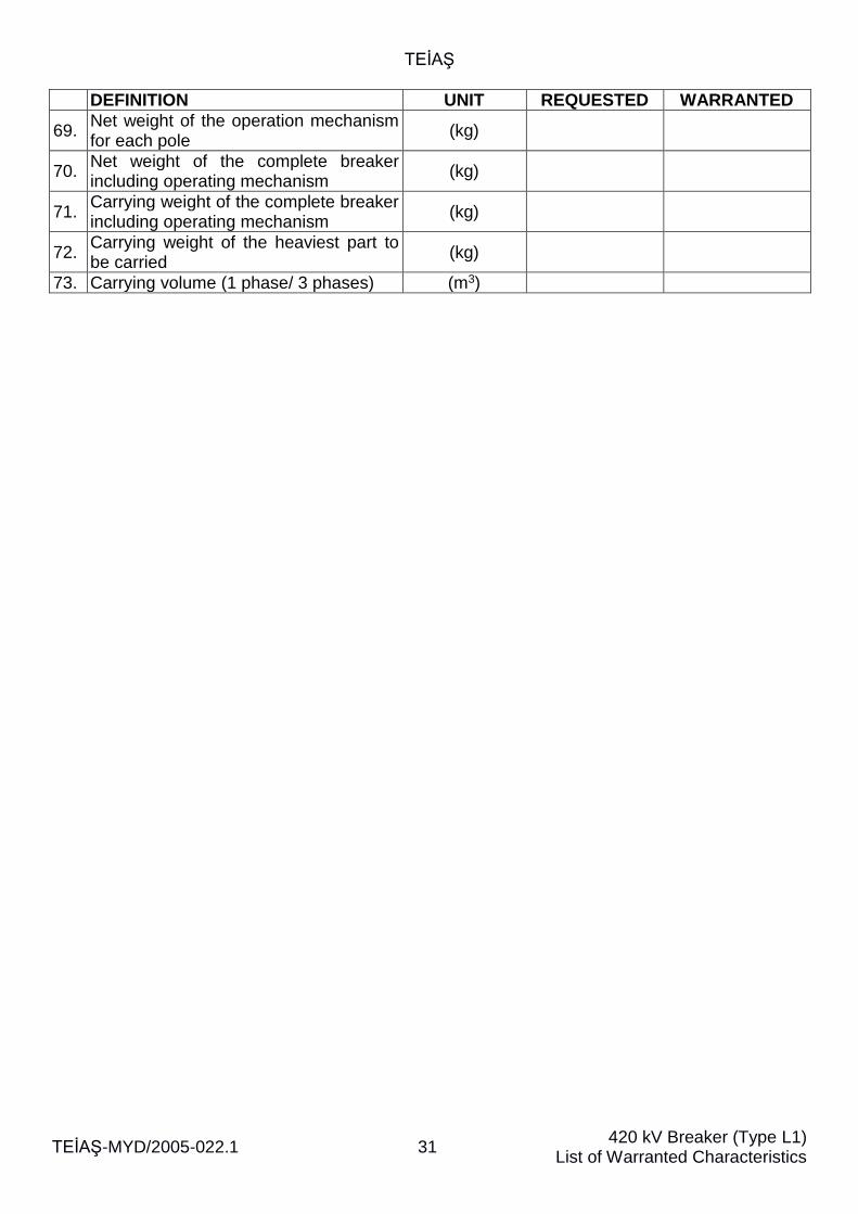
69. Net weight of the operation mechanism for each pole
(kg)
70. Net weight of the complete breaker including operating mechanism
(kg)
71. Carrying weight of the complete breaker including operating mechanism
(kg)
72. Carrying weight of the heaviest part to be carried
(kg)
73. Carrying volume (1 phase/ 3 phases) (m3)
TEİAŞ
TEİAŞ-MYD/2005-022.1 32 420 kV Breaker (Type L2)
List of Warranted Characteristics
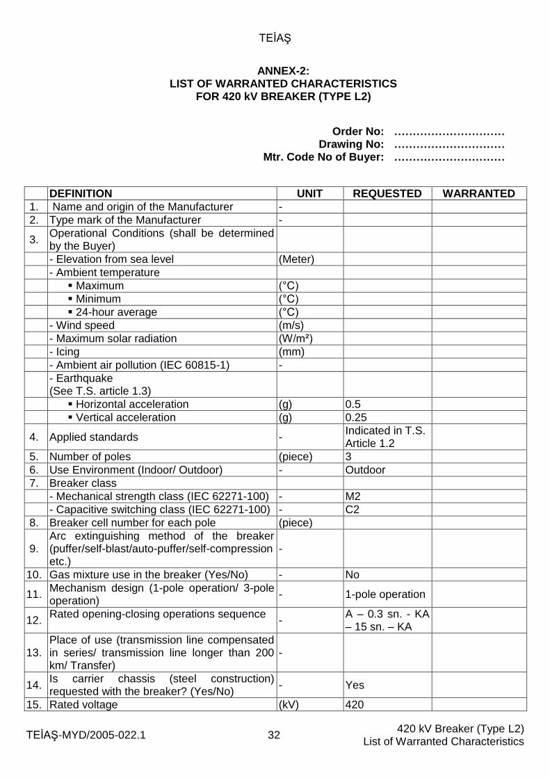
ANNEX-2: LIST OF WARRANTED CHARACTERISTICS
FOR 420 kV BREAKER (TYPE L2)
Order No: ………………………… Drawing No: ………………………… Mtr. Code No of Buyer: …………………………
DEFINITION UNIT REQUESTED WARRANTED
1. Name and origin of the Manufacturer -
2. Type mark of the Manufacturer -
3. Operational Conditions (shall be determined by the Buyer)
- Elevation from sea level (Meter)
- Ambient temperature
Maximum (°C)
Minimum (°C)
24-hour average (°C)
- Wind speed (m/s)
- Maximum solar radiation (W/m²)
- Icing (mm)
- Ambient air pollution (IEC 60815-1) -
- Earthquake (See T.S. article 1.3)
Horizontal acceleration (g) 0.5
Vertical acceleration (g) 0.25
4. Applied standards - Indicated in T.S. Article 1.2
5. Number of poles (piece) 3
6. Use Environment (Indoor/ Outdoor) - Outdoor
7. Breaker class
- Mechanical strength class (IEC 62271-100) - M2
- Capacitive switching class (IEC 62271-100) - C2
8. Breaker cell number for each pole (piece)
9. Arc extinguishing method of the breaker (puffer/self-blast/auto-puffer/self-compression etc.)
-
10. Gas mixture use in the breaker (Yes/No) - No
11. Mechanism design (1-pole operation/ 3-pole operation)
- 1-pole operation
12. Rated opening-closing operations sequence
- A – 0.3 sn. - KA – 15 sn. – KA
13. Place of use (transmission line compensated in series/ transmission line longer than 200 km/ Transfer)
-
14. Is carrier chassis (steel construction) requested with the breaker? (Yes/No)
- Yes
15. Rated voltage (kV) 420
TEİAŞ
TEİAŞ-MYD/2005-022.1 33 420 kV Breaker (Type L2)
List of Warranted Characteristics
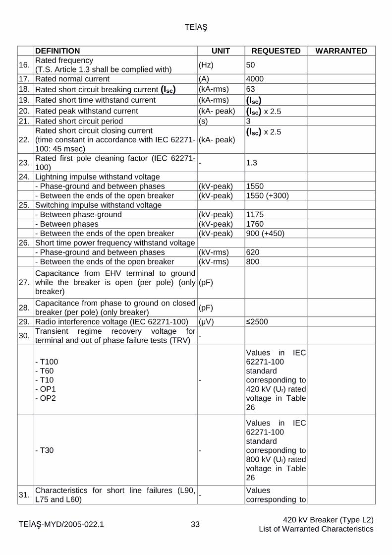
DEFINITION UNIT REQUESTED WARRANTED
16. Rated frequency (T.S. Article 1.3 shall be complied with)
(Hz) 50
17. Rated normal current (A) 4000
18. Rated short circuit breaking current (Isc) (kA-rms) 63
19. Rated short time withstand current (kA-rms) (Isc)
20. Rated peak withstand current (kA- peak) (Isc) x 2.5
21. Rated short circuit period (s) 3
22. Rated short circuit closing current (time constant in accordance with IEC 62271-100: 45 msec)
(kA- peak) (Isc) x 2.5
23. Rated first pole cleaning factor (IEC 62271-100)
- 1.3
24. Lightning impulse withstand voltage
- Phase-ground and between phases (kV-peak) 1550
- Between the ends of the open breaker (kV-peak) 1550 (+300)
25. Switching impulse withstand voltage
- Between phase-ground (kV-peak) 1175
- Between phases (kV-peak) 1760
- Between the ends of the open breaker (kV-peak) 900 (+450)
26. Short time power frequency withstand voltage
- Phase-ground and between phases (kV-rms) 620
- Between the ends of the open breaker (kV-rms) 800
27. Capacitance from EHV terminal to ground while the breaker is open (per pole) (only breaker)
(pF)
28. Capacitance from phase to ground on closed breaker (per pole) (only breaker)
(pF)
29. Radio interference voltage (IEC 62271-100) (µV) ≤2500
30. Transient regime recovery voltage for terminal and out of phase failure tests (TRV)
-
- T100 - T60 - T10 - OP1 - OP2
-
Values in IEC 62271-100 standard corresponding to 420 kV (Ur) rated voltage in Table 26
- T30 -
Values in IEC 62271-100 standard corresponding to 800 kV (Ur) rated voltage in Table 26
31. Characteristics for short line failures (L90, L75 and L60)
- Values corresponding to

TEİAŞ
TEİAŞ-MYD/2005-022.1 34 420 kV Breaker (Type L2)
List of Warranted Characteristics
DEFINITION UNIT REQUESTED WARRANTED
420 kV rated voltage in IEC 62271-100, Table 49
32. Rated out-of-phase breaking current (kA-rms) (kA-rms) (Isc) x 25 %
33. Rated capacitive switching currents (A)
Values corresponding to 420 kV rated voltage in IEC 62271-100, Table 9
34. Additional equipment characteristics of the breaker;
- Is controlled switching device requested?
(Yes/No) - No
- Is closing resistance requested? (Yes/No) - Yes
- Is grading capacitor requested? (Yes/No) - Yes
35. Closing resistances (if requested)
- Tip -
- Resistance value (ohm/phase) 400
- Pre-insertion time (msec) 6-8
- Minimum number of KA-15 sec - KA loops without exceeding the thermal capacity of resistances while the line is short circuited or in no load condition with 500 km long line
4
- Thermal time constant of resistances -
36. Grading capacitors (if requested)
- Tip -
- Capacitance value (pF)
37. Capacitance reduction, if any, during rated opening- closing operations
-
38. Breaker times
- Opening time (msec)
- Closing time (msec) 110
- Rated break time (msec) 45
- Arcing time (arcing time) (msec)
- Pre-arcing time (msec)
- Close-open time (msec)
- Open - close time (msec)
- Make time (msec)
39.
Critical current and arcing time in case of critical current (If necessary in accordance with IEC 62271-100 criteria)
(msec)
40. Maximum time difference between the first closing pole and last closing pole
(msec) 5
41. Maximum time difference between the units (msec) 3.3
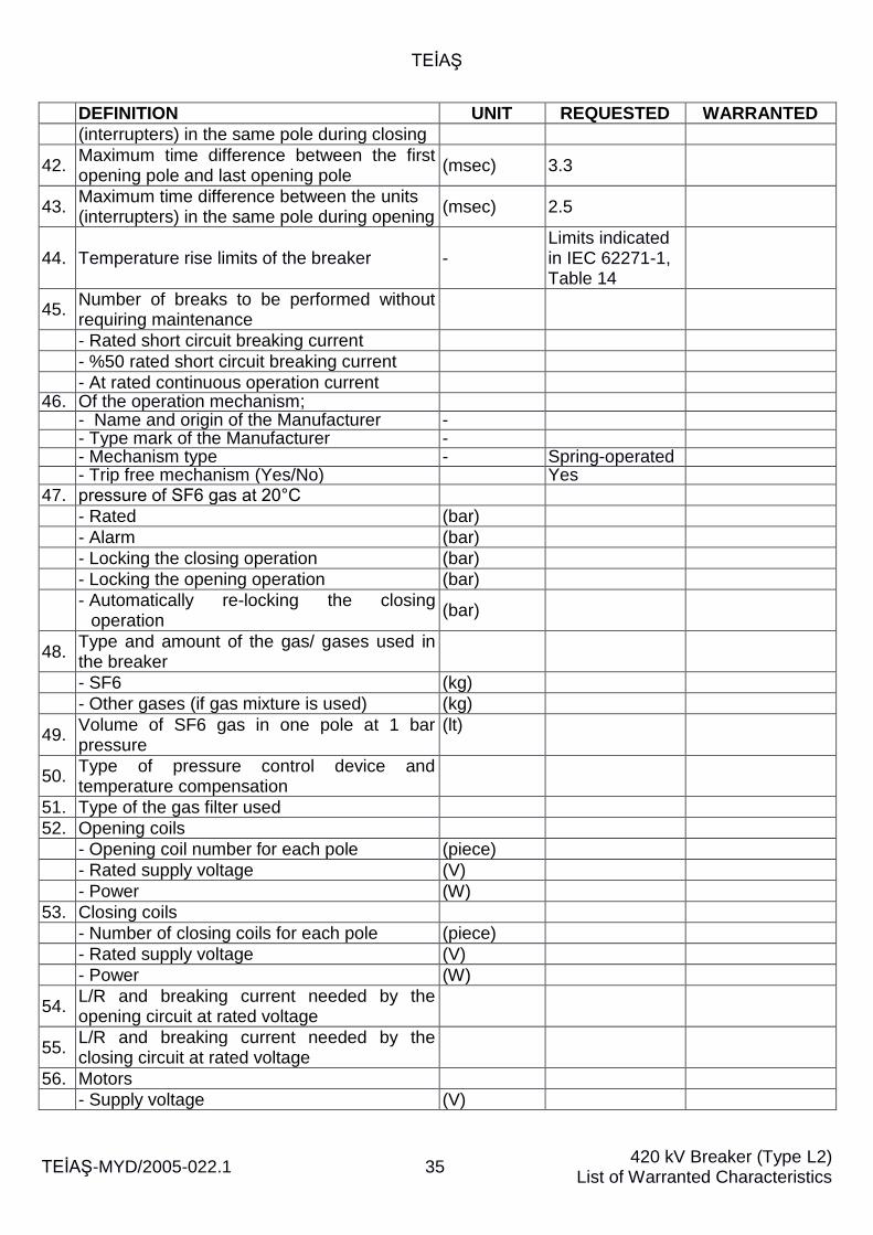
TEİAŞ
TEİAŞ-MYD/2005-022.1 35 420 kV Breaker (Type L2)
List of Warranted Characteristics
DEFINITION UNIT REQUESTED WARRANTED
(interrupters) in the same pole during closing
42. Maximum time difference between the first opening pole and last opening pole
(msec) 3.3
43. Maximum time difference between the units (interrupters) in the same pole during opening
(msec) 2.5
44. Temperature rise limits of the breaker - Limits indicated in IEC 62271-1, Table 14
45. Number of breaks to be performed without requiring maintenance
- Rated short circuit breaking current
- %50 rated short circuit breaking current
- At rated continuous operation current 46. Of the operation mechanism;
- Name and origin of the Manufacturer - - Type mark of the Manufacturer - - Mechanism type - Spring-operated - Trip free mechanism (Yes/No) Yes
47. pressure of SF6 gas at 20°C
- Rated (bar)
- Alarm (bar)
- Locking the closing operation (bar)
- Locking the opening operation (bar)
- Automatically re-locking the closing
operation (bar)
48. Type and amount of the gas/ gases used in the breaker
- SF6 (kg)
- Other gases (if gas mixture is used) (kg)
49. Volume of SF6 gas in one pole at 1 bar pressure
(lt)
50. Type of pressure control device and temperature compensation
51. Type of the gas filter used
52. Opening coils
- Opening coil number for each pole (piece)
- Rated supply voltage (V)
- Power (W)
53. Closing coils
- Number of closing coils for each pole (piece)
- Rated supply voltage (V)
- Power (W)
54. L/R and breaking current needed by the opening circuit at rated voltage
55. L/R and breaking current needed by the closing circuit at rated voltage
56. Motors
- Supply voltage (V)
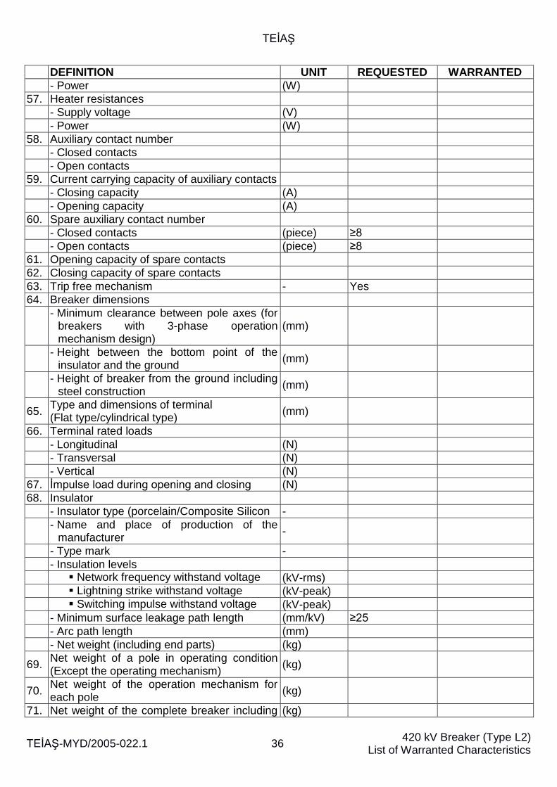
TEİAŞ
TEİAŞ-MYD/2005-022.1 36 420 kV Breaker (Type L2)
List of Warranted Characteristics
DEFINITION UNIT REQUESTED WARRANTED
- Power (W)
57. Heater resistances
- Supply voltage (V)
- Power (W)
58. Auxiliary contact number
- Closed contacts
- Open contacts
59. Current carrying capacity of auxiliary contacts
- Closing capacity (A)
- Opening capacity (A)
60. Spare auxiliary contact number
- Closed contacts (piece) ≥8
- Open contacts (piece) ≥8
61. Opening capacity of spare contacts
62. Closing capacity of spare contacts
63. Trip free mechanism - Yes
64. Breaker dimensions
- Minimum clearance between pole axes (for
breakers with 3-phase operation mechanism design)
(mm)
- Height between the bottom point of the
insulator and the ground (mm)
- Height of breaker from the ground including
steel construction (mm)
65. Type and dimensions of terminal (Flat type/cylindrical type)
(mm)
66. Terminal rated loads
- Longitudinal (N)
- Transversal (N)
- Vertical (N)
67. İmpulse load during opening and closing (N)
68. Insulator
- Insulator type (porcelain/Composite Silicon -
- Name and place of production of the
manufacturer -
- Type mark -
- Insulation levels
Network frequency withstand voltage (kV-rms)
Lightning strike withstand voltage (kV-peak)
Switching impulse withstand voltage (kV-peak)
- Minimum surface leakage path length (mm/kV) ≥25
- Arc path length (mm)
- Net weight (including end parts) (kg)
69. Net weight of a pole in operating condition (Except the operating mechanism)
(kg)
70. Net weight of the operation mechanism for each pole
(kg)
71. Net weight of the complete breaker including (kg)
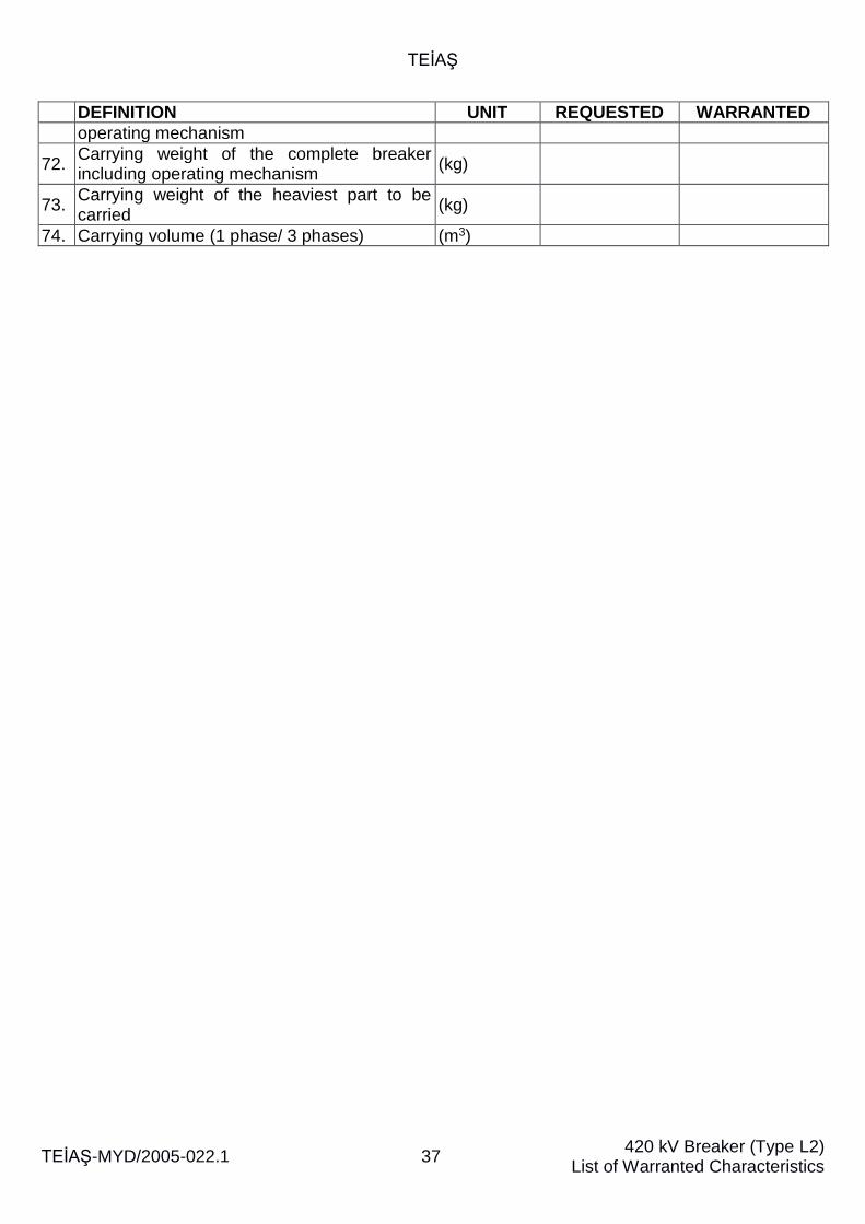
TEİAŞ
TEİAŞ-MYD/2005-022.1 37 420 kV Breaker (Type L2)
List of Warranted Characteristics
DEFINITION UNIT REQUESTED WARRANTED
operating mechanism
72. Carrying weight of the complete breaker including operating mechanism
(kg)
73. Carrying weight of the heaviest part to be carried
(kg)
74. Carrying volume (1 phase/ 3 phases) (m3)
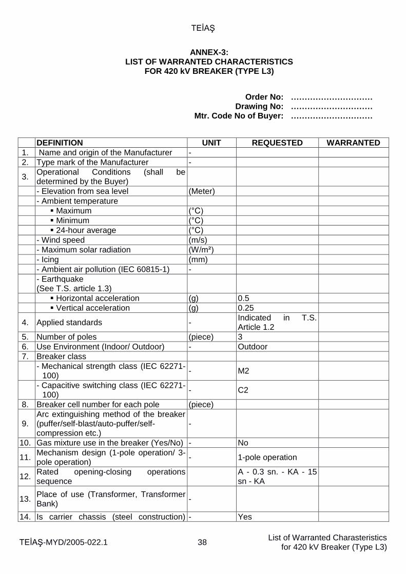
TEİAŞ
TEİAŞ-MYD/2005-022.1 38 List of Warranted Charasteristics
for 420 kV Breaker (Type L3)
ANNEX-3: LIST OF WARRANTED CHARACTERISTICS
FOR 420 kV BREAKER (TYPE L3)
Order No: ………………………… Drawing No: ………………………… Mtr. Code No of Buyer: …………………………
DEFINITION UNIT REQUESTED WARRANTED
1. Name and origin of the Manufacturer -
2. Type mark of the Manufacturer -
3. Operational Conditions (shall be determined by the Buyer)
- Elevation from sea level (Meter)
- Ambient temperature
Maximum (°C)
Minimum (°C)
24-hour average (°C)
- Wind speed (m/s)
- Maximum solar radiation (W/m²)
- Icing (mm)
- Ambient air pollution (IEC 60815-1) -
- Earthquake (See T.S. article 1.3)
Horizontal acceleration (g) 0.5
Vertical acceleration (g) 0.25
4. Applied standards - Indicated in T.S. Article 1.2
5. Number of poles (piece) 3
6. Use Environment (Indoor/ Outdoor) - Outdoor
7. Breaker class
- Mechanical strength class (IEC 62271-
100) - M2
- Capacitive switching class (IEC 62271-
100) - C2
8. Breaker cell number for each pole (piece)
9. Arc extinguishing method of the breaker (puffer/self-blast/auto-puffer/self-compression etc.)
-
10. Gas mixture use in the breaker (Yes/No) - No
11. Mechanism design (1-pole operation/ 3-pole operation)
- 1-pole operation
12. Rated opening-closing operations sequence
A - 0.3 sn. - KA - 15 sn - KA
13. Place of use (Transformer, Transformer Bank)
-
14. Is carrier chassis (steel construction) - Yes

TEİAŞ
TEİAŞ-MYD/2005-022.1 39 List of Warranted Charasteristics
for 420 kV Breaker (Type L3)
DEFINITION UNIT REQUESTED WARRANTED
requested with the breaker? (Yes/No)
15. Rated voltage (kV) 420
16. Rated frequency (Hz) 50 (T.S. Article 1.3 shall be complied with)
17. Rated normal current (A) 4000
18. Rated short circuit breaking current (Isc) (kA-rms) 63
19. Rated short time withstand current (kA-rms) (Isc)
20. Rated peak withstand current (kA- peak) (Isc) x 2.5
21. Rated short circuit period (s) 3
22. Rated short circuit closing current (time constant in accordance with IEC 62271-100: 45 msec)
(kA- peak) (Isc) x 2.5
23. Rated first pole cleaning factor (IEC 62271-100)
- 1.3
24. Lightning impulse withstand voltage
- Phase-ground and between phases (kV-peak) 1550
- Between the ends of the open breaker (kV-peak) 1550 (+300)
25. Switching impulse withstand voltage
- Between phase-ground (kV-peak) 1175
- Between phases (kV-peak) 1760
- Between the ends of the open breaker (kV-peak) 900 (+450)
26. Short time power frequency withstand voltage
- Phase-ground and between phases (kV-rms) 620
- Between the ends of the open breaker (kV-rms) 800
27. Capacitance from EHV terminal to ground while the breaker is open (per pole) (only breaker)
(pF)
28. Capacitance from phase to ground on closed breaker (per pole) (only breaker)
(pF)
29. Radio interference voltage (IEC 62271-100)
(µV) ≤2500
30. Transient regime recovery voltage for terminal and out of phase failure tests (TRV)
- T100 - T60 - T30 - T10 - OP1, OP2
-
Values in IEC 62271-100 standard corresponding to 420 kV (Uf) rated voltage in Table 26
31. Rated out-of-phase breaking current (kA-rms) (kA-rms)
(Isc) x 25 %
32. Rated capacitive switching currents (A) Values corresponding to 420
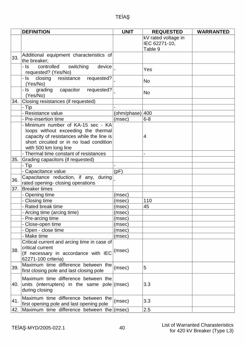
TEİAŞ
TEİAŞ-MYD/2005-022.1 40 List of Warranted Charasteristics
for 420 kV Breaker (Type L3)
DEFINITION UNIT REQUESTED WARRANTED
kV rated voltage in IEC 62271-10, Table 9
33. Additional equipment characteristics of the breaker;
- Is controlled switching device
requested? (Yes/No) - Yes
- Is closing resistance requested?
(Yes/No) - No
- Is grading capacitor requested?
(Yes/No) - No
34. Closing resistances (if requested)
- Tip -
- Resistance value (ohm/phase) 400
- Pre-insertion time (msec) 6-8
- Minimum number of KA-15 sec - KA loops without exceeding the thermal capacity of resistances while the line is short circuited or in no load condition with 500 km long line
4
- Thermal time constant of resistances -
35. Grading capacitors (if requested)
- Tip -
- Capacitance value (pF)
36. Capacitance reduction, if any, during rated opening- closing operations
-
37. Breaker times
- Opening time (msec)
- Closing time (msec) 110
- Rated break time (msec) 45
- Arcing time (arcing time) (msec)
- Pre-arcing time (msec)
- Close-open time (msec)
- Open - close time (msec)
- Make time (msec)
38.
Critical current and arcing time in case of critical current (If necessary in accordance with IEC 62271-100 criteria)
(msec)
39. Maximum time difference between the first closing pole and last closing pole
(msec) 5
40. Maximum time difference between the units (interrupters) in the same pole during closing
(msec) 3.3
41. Maximum time difference between the first opening pole and last opening pole
(msec) 3.3
42. Maximum time difference between the (msec) 2.5
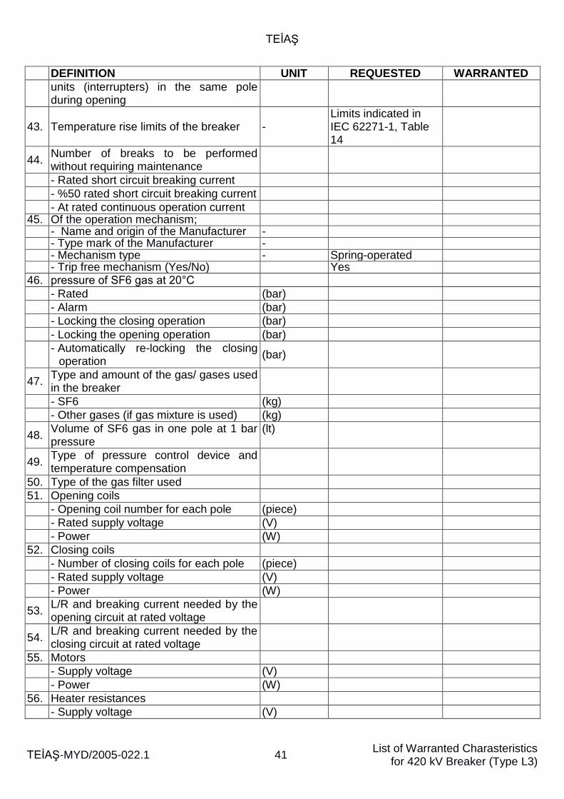
TEİAŞ
TEİAŞ-MYD/2005-022.1 41 List of Warranted Charasteristics
for 420 kV Breaker (Type L3)
DEFINITION UNIT REQUESTED WARRANTED
units (interrupters) in the same pole during opening
43. Temperature rise limits of the breaker - Limits indicated in IEC 62271-1, Table 14
44. Number of breaks to be performed without requiring maintenance
- Rated short circuit breaking current
- %50 rated short circuit breaking current
- At rated continuous operation current 45. Of the operation mechanism;
- Name and origin of the Manufacturer - - Type mark of the Manufacturer - - Mechanism type - Spring-operated - Trip free mechanism (Yes/No) Yes
46. pressure of SF6 gas at 20°C
- Rated (bar)
- Alarm (bar)
- Locking the closing operation (bar)
- Locking the opening operation (bar)
- Automatically re-locking the closing
operation (bar)
47. Type and amount of the gas/ gases used in the breaker
- SF6 (kg)
- Other gases (if gas mixture is used) (kg)
48. Volume of SF6 gas in one pole at 1 bar pressure
(lt)
49. Type of pressure control device and temperature compensation
50. Type of the gas filter used
51. Opening coils
- Opening coil number for each pole (piece)
- Rated supply voltage (V)
- Power (W)
52. Closing coils
- Number of closing coils for each pole (piece)
- Rated supply voltage (V)
- Power (W)
53. L/R and breaking current needed by the opening circuit at rated voltage
54. L/R and breaking current needed by the closing circuit at rated voltage
55. Motors
- Supply voltage (V)
- Power (W)
56. Heater resistances
- Supply voltage (V)
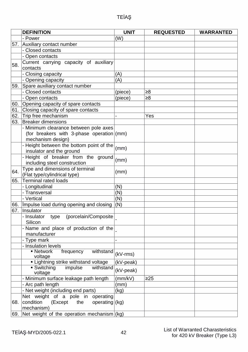
TEİAŞ
TEİAŞ-MYD/2005-022.1 42 List of Warranted Charasteristics
for 420 kV Breaker (Type L3)
DEFINITION UNIT REQUESTED WARRANTED
- Power (W)
57. Auxiliary contact number
- Closed contacts
- Open contacts
58. Current carrying capacity of auxiliary contacts
- Closing capacity (A)
- Opening capacity (A)
59. Spare auxiliary contact number
- Closed contacts (piece) ≥8
- Open contacts (piece) ≥8
60. Opening capacity of spare contacts
61. Closing capacity of spare contacts
62. Trip free mechanism - Yes
63. Breaker dimensions
- Minimum clearance between pole axes
(for breakers with 3-phase operation mechanism design)
(mm)
- Height between the bottom point of the
insulator and the ground (mm)
- Height of breaker from the ground
including steel construction (mm)
64. Type and dimensions of terminal (Flat type/cylindrical type)
(mm)
65. Terminal rated loads
- Longitudinal (N)
- Transversal (N)
- Vertical (N)
66. İmpulse load during opening and closing (N)
67. Insulator
- Insulator type (porcelain/Composite
Silicon -
- Name and place of production of the
manufacturer -
- Type mark -
- Insulation levels
Network frequency withstand
voltage (kV-rms)
Lightning strike withstand voltage (kV-peak)
Switching impulse withstand
voltage (kV-peak)
- Minimum surface leakage path length (mm/kV) ≥25
- Arc path length (mm)
- Net weight (including end parts) (kg)
68. Net weight of a pole in operating condition (Except the operating mechanism)
(kg)
69. Net weight of the operation mechanism (kg)
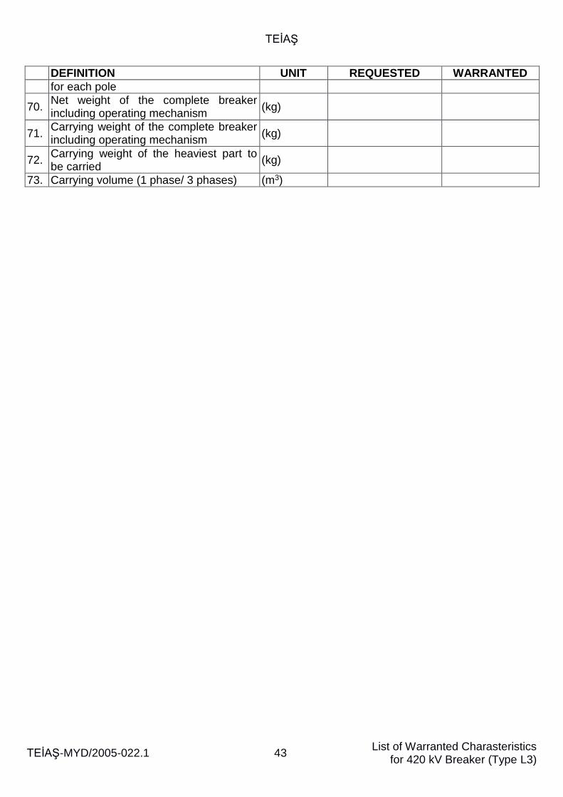
TEİAŞ
TEİAŞ-MYD/2005-022.1 43 List of Warranted Charasteristics
for 420 kV Breaker (Type L3)
DEFINITION UNIT REQUESTED WARRANTED
for each pole
70. Net weight of the complete breaker including operating mechanism
(kg)
71. Carrying weight of the complete breaker including operating mechanism
(kg)
72. Carrying weight of the heaviest part to be carried
(kg)
73. Carrying volume (1 phase/ 3 phases) (m3)
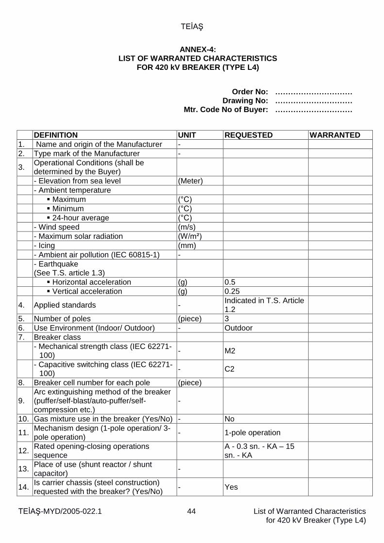
TEİAŞ
TEİAŞ-MYD/2005-022.1 44
List of Warranted Characteristics for 420 kV Breaker (Type L4)
ANNEX-4: LIST OF WARRANTED CHARACTERISTICS
FOR 420 kV BREAKER (TYPE L4)
Order No: ………………………… Drawing No: ………………………… Mtr. Code No of Buyer: …………………………
DEFINITION UNIT REQUESTED WARRANTED
1. Name and origin of the Manufacturer -
2. Type mark of the Manufacturer -
3. Operational Conditions (shall be determined by the Buyer)
- Elevation from sea level (Meter)
- Ambient temperature
Maximum (°C)
Minimum (°C)
24-hour average (°C)
- Wind speed (m/s)
- Maximum solar radiation (W/m²)
- Icing (mm)
- Ambient air pollution (IEC 60815-1) -
- Earthquake (See T.S. article 1.3)
Horizontal acceleration (g) 0.5
Vertical acceleration (g) 0.25
4. Applied standards - Indicated in T.S. Article 1.2
5. Number of poles (piece) 3
6. Use Environment (Indoor/ Outdoor) - Outdoor
7. Breaker class
- Mechanical strength class (IEC 62271-
100) - M2
- Capacitive switching class (IEC 62271-
100) - C2
8. Breaker cell number for each pole (piece)
9. Arc extinguishing method of the breaker (puffer/self-blast/auto-puffer/self-compression etc.)
-
10. Gas mixture use in the breaker (Yes/No) - No
11. Mechanism design (1-pole operation/ 3-pole operation)
- 1-pole operation
12. Rated opening-closing operations sequence
A - 0.3 sn. - KA – 15 sn. - KA
13. Place of use (shunt reactor / shunt capacitor)
-
14. Is carrier chassis (steel construction) requested with the breaker? (Yes/No)
- Yes
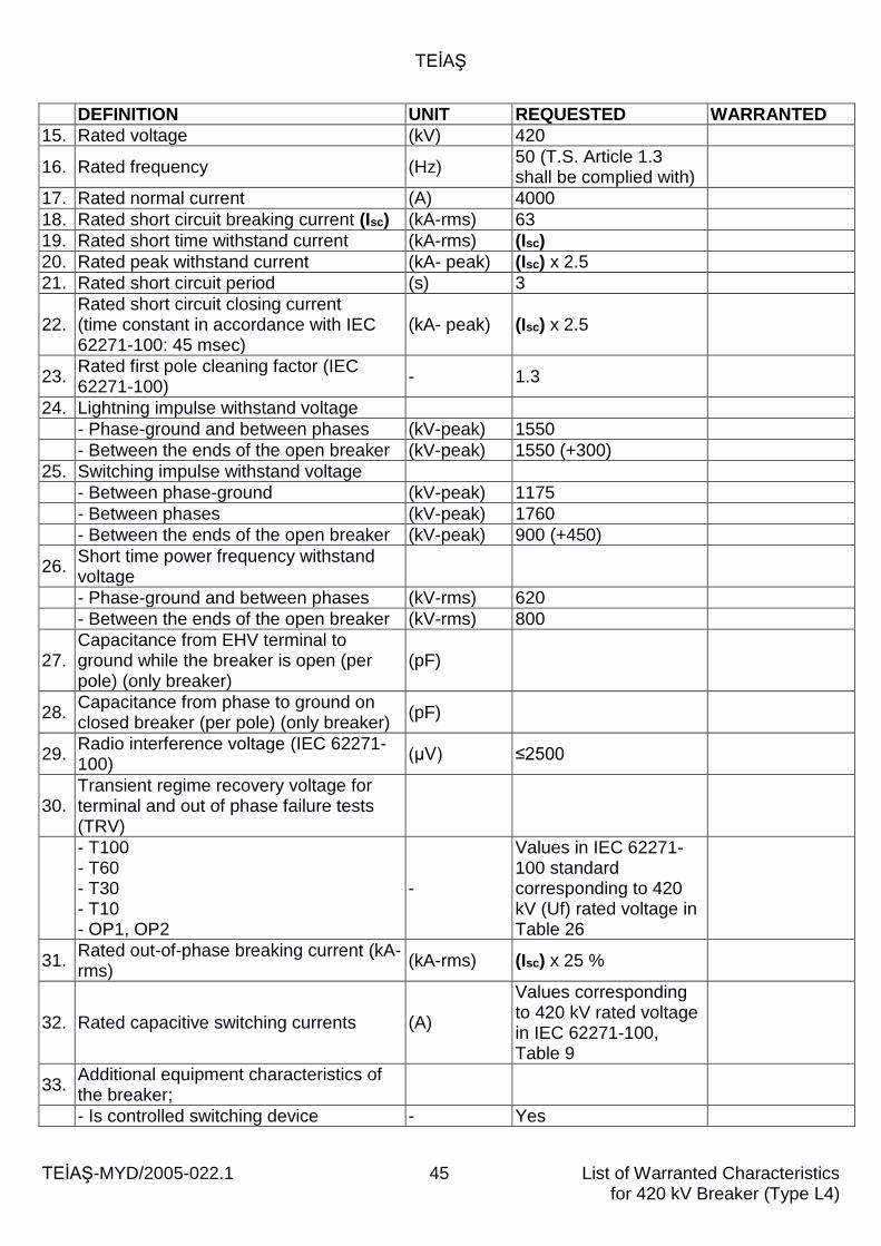
TEİAŞ
TEİAŞ-MYD/2005-022.1 45
List of Warranted Characteristics for 420 kV Breaker (Type L4)
DEFINITION UNIT REQUESTED WARRANTED
15. Rated voltage (kV) 420
16. Rated frequency (Hz) 50 (T.S. Article 1.3 shall be complied with)
17. Rated normal current (A) 4000
18. Rated short circuit breaking current (Isc) (kA-rms) 63
19. Rated short time withstand current (kA-rms) (Isc)
20. Rated peak withstand current (kA- peak) (Isc) x 2.5
21. Rated short circuit period (s) 3
22. Rated short circuit closing current (time constant in accordance with IEC 62271-100: 45 msec)
(kA- peak) (Isc) x 2.5
23. Rated first pole cleaning factor (IEC 62271-100)
- 1.3
24. Lightning impulse withstand voltage
- Phase-ground and between phases (kV-peak) 1550
- Between the ends of the open breaker (kV-peak) 1550 (+300)
25. Switching impulse withstand voltage
- Between phase-ground (kV-peak) 1175
- Between phases (kV-peak) 1760
- Between the ends of the open breaker (kV-peak) 900 (+450)
26. Short time power frequency withstand voltage
- Phase-ground and between phases (kV-rms) 620
- Between the ends of the open breaker (kV-rms) 800
27. Capacitance from EHV terminal to ground while the breaker is open (per pole) (only breaker)
(pF)
28. Capacitance from phase to ground on closed breaker (per pole) (only breaker)
(pF)
29. Radio interference voltage (IEC 62271-100)
(µV) ≤2500
30. Transient regime recovery voltage for terminal and out of phase failure tests (TRV)
- T100 - T60 - T30 - T10 - OP1, OP2
-
Values in IEC 62271-100 standard corresponding to 420 kV (Uf) rated voltage in Table 26
31. Rated out-of-phase breaking current (kA-rms)
(kA-rms) (Isc) x 25 %
32. Rated capacitive switching currents (A)
Values corresponding to 420 kV rated voltage in IEC 62271-100, Table 9
33. Additional equipment characteristics of the breaker;
- Is controlled switching device - Yes
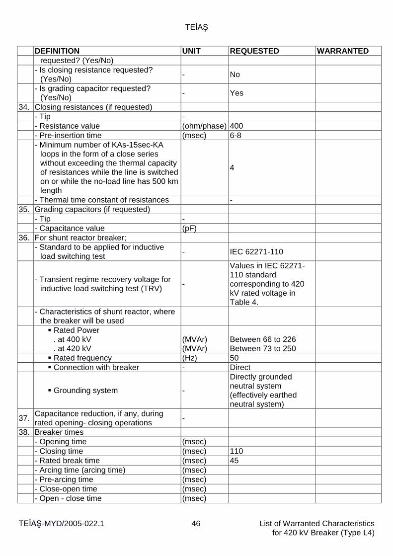
TEİAŞ
TEİAŞ-MYD/2005-022.1 46
List of Warranted Characteristics for 420 kV Breaker (Type L4)
DEFINITION UNIT REQUESTED WARRANTED
requested? (Yes/No)
- Is closing resistance requested?
(Yes/No) - No
- Is grading capacitor requested?
(Yes/No) - Yes
34. Closing resistances (if requested)
- Tip -
- Resistance value (ohm/phase) 400
- Pre-insertion time (msec) 6-8
- Minimum number of KAs-15sec-KA loops in the form of a close series without exceeding the thermal capacity of resistances while the line is switched on or while the no-load line has 500 km length
4
- Thermal time constant of resistances -
35. Grading capacitors (if requested)
- Tip -
- Capacitance value (pF)
36. For shunt reactor breaker;
- Standard to be applied for inductive
load switching test - IEC 62271-110
- Transient regime recovery voltage for
inductive load switching test (TRV) -
Values in IEC 62271-110 standard corresponding to 420 kV rated voltage in Table 4.
- Characteristics of shunt reactor, where
the breaker will be used
Rated Power
. at 400 kV
. at 420 kV
(MVAr) (MVAr)
Between 66 to 226 Between 73 to 250
Rated frequency (Hz) 50
Connection with breaker - Direct
Grounding system -
Directly grounded neutral system (effectively earthed neutral system)
37. Capacitance reduction, if any, during rated opening- closing operations
-
38. Breaker times
- Opening time (msec)
- Closing time (msec) 110
- Rated break time (msec) 45
- Arcing time (arcing time) (msec)
- Pre-arcing time (msec)
- Close-open time (msec)
- Open - close time (msec)
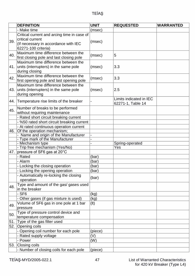
TEİAŞ
TEİAŞ-MYD/2005-022.1 47
List of Warranted Characteristics for 420 kV Breaker (Type L4)
DEFINITION UNIT REQUESTED WARRANTED
- Make time (msec)
39.
Critical current and arcing time in case of critical current (If necessary in accordance with IEC 62271-100 criteria)
(msec)
40. Maximum time difference between the first closing pole and last closing pole
(msec) 5
41. Maximum time difference between the units (interrupters) in the same pole during closing
(msec) 3.3
42. Maximum time difference between the first opening pole and last opening pole
(msec) 3.3
43. Maximum time difference between the units (interrupters) in the same pole during opening
(msec) 2.5
44. Temperature rise limits of the breaker - Limits indicated in IEC 62271-1, Table 14
45. Number of breaks to be performed without requiring maintenance
- Rated short circuit breaking current
- %50 rated short circuit breaking current
- At rated continuous operation current 46. Of the operation mechanism;
- Name and origin of the Manufacturer - - Type mark of the Manufacturer - - Mechanism type - Spring-operated - Trip free mechanism (Yes/No) Yes
47. pressure of SF6 gas at 20°C
- Rated (bar)
- Alarm (bar)
- Locking the closing operation (bar)
- Locking the opening operation (bar)
- Automatically re-locking the closing
operation (bar)
48. Type and amount of the gas/ gases used in the breaker
- SF6 (kg)
- Other gases (if gas mixture is used) (kg)
49. Volume of SF6 gas in one pole at 1 bar pressure
(lt)
50. Type of pressure control device and temperature compensation
51. Type of the gas filter used
52. Opening coils
- Opening coil number for each pole (piece)
- Rated supply voltage (V)
- Power (W)
53. Closing coils
- Number of closing coils for each pole (piece)
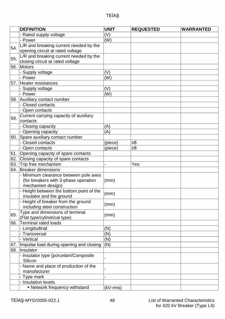
TEİAŞ
TEİAŞ-MYD/2005-022.1 48
List of Warranted Characteristics for 420 kV Breaker (Type L4)
DEFINITION UNIT REQUESTED WARRANTED
- Rated supply voltage (V)
- Power (W)
54. L/R and breaking current needed by the opening circuit at rated voltage
55. L/R and breaking current needed by the closing circuit at rated voltage
56. Motors
- Supply voltage (V)
- Power (W)
57. Heater resistances
- Supply voltage (V)
- Power (W)
58. Auxiliary contact number
- Closed contacts
- Open contacts
59. Current carrying capacity of auxiliary contacts
- Closing capacity (A)
- Opening capacity (A)
60. Spare auxiliary contact number
- Closed contacts (piece) ≥8
- Open contacts (piece) ≥8
61. Opening capacity of spare contacts
62. Closing capacity of spare contacts
63. Trip free mechanism - Yes
64. Breaker dimensions
- Minimum clearance between pole axes
(for breakers with 3-phase operation mechanism design)
(mm)
- Height between the bottom point of the
insulator and the ground (mm)
- Height of breaker from the ground
including steel construction (mm)
65. Type and dimensions of terminal (Flat type/cylindrical type)
(mm)
66. Terminal rated loads
- Longitudinal (N)
- Transversal (N)
- Vertical (N)
67. İmpulse load during opening and closing (N)
68. Insulator
- Insulator type (porcelain/Composite
Silicon -
- Name and place of production of the
manufacturer -
- Type mark -
- Insulation levels
Network frequency withstand (kV-rms)
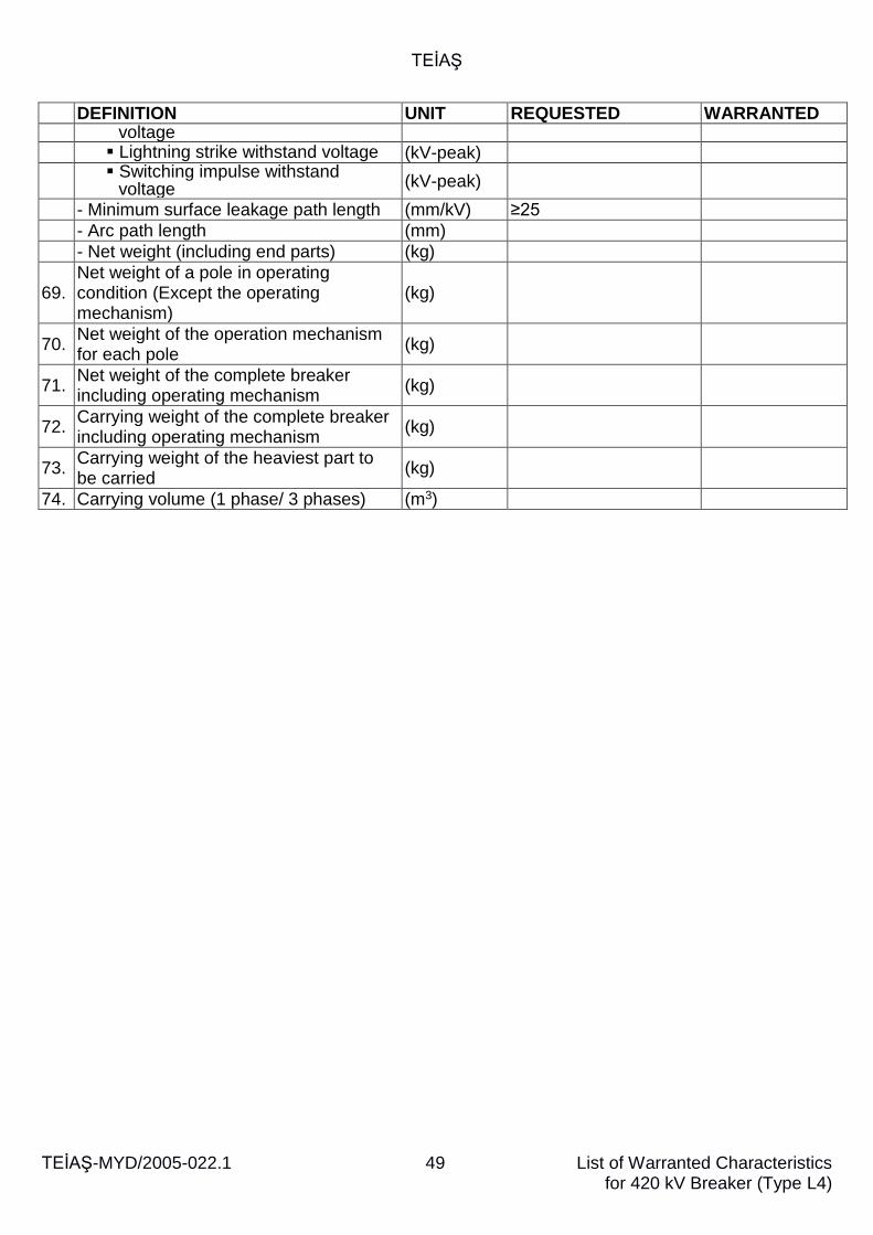
TEİAŞ
TEİAŞ-MYD/2005-022.1 49
List of Warranted Characteristics for 420 kV Breaker (Type L4)
DEFINITION UNIT REQUESTED WARRANTED voltage
Lightning strike withstand voltage (kV-peak)
Switching impulse withstand
voltage (kV-peak)
- Minimum surface leakage path length (mm/kV) ≥25
- Arc path length (mm)
- Net weight (including end parts) (kg)
69. Net weight of a pole in operating condition (Except the operating mechanism)
(kg)
70. Net weight of the operation mechanism for each pole
(kg)
71. Net weight of the complete breaker including operating mechanism
(kg)
72. Carrying weight of the complete breaker including operating mechanism
(kg)
73. Carrying weight of the heaviest part to be carried
(kg)
74. Carrying volume (1 phase/ 3 phases) (m3)
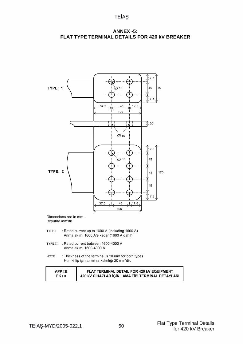
TEİAŞ
TEİAŞ-MYD/2005-022.1 50 Flat Type Terminal Details
for 420 kV Breaker
ANNEX -5: FLAT TYPE TERMINAL DETAILS FOR 420 kV BREAKER
TEİAŞ
TEİAŞ-MYD/2005-022.1 51 List of Deviations for 420 kV Breaker
ANNEX-6: LIST OF DEVIATIONS FOR 420 kV BREAKER
Order No.: ..................... Drawing No. .: ................
Mtr. Code No of Buyer: ................ A- DEVIATIONS FROM TECHNICAL SPECIFICATIONS (The articles, from which there are deviations, and what those deviations are shall be clearly indicated by the bidder).
……………………………………………………………….
……………………………………………………………….
……………………………………………………………….
……………………………………………………………….
……………………………………………………………….
……………………………………………………………….
………………………………………………………………… B- DEVIATIONS IN THE LIST OF WARRANTED CHARACTERISTICS (The articles, from which there are deviations, and what those deviations are shall be clearly indicated by the bidder).
……………………………………………………………….
……………………………………………………………….
……………………………………………………………….
..………………………………………………………………
Related Documents